US5622394A - Corrosion-resistant joint - Google Patents
Corrosion-resistant jointDownload PDFInfo
- Publication number
- US5622394A US5622394AUS08/404,517US40451795AUS5622394AUS 5622394 AUS5622394 AUS 5622394AUS 40451795 AUS40451795 AUS 40451795AUS 5622394 AUS5622394 AUS 5622394A
- Authority
- US
- United States
- Prior art keywords
- hose
- tube
- metal
- joint
- plastic
- Prior art date
- Legal status (The legal status is an assumption and is not a legal conclusion. Google has not performed a legal analysis and makes no representation as to the accuracy of the status listed.)
- Expired - Lifetime
Links
- 238000005260corrosionMethods0.000titleclaimsabstractdescription16
- 230000007797corrosionEffects0.000titleclaimsabstractdescription16
- 239000002184metalSubstances0.000claimsabstractdescription55
- 239000004033plasticSubstances0.000claimsabstractdescription30
- 230000014759maintenance of locationEffects0.000claimsabstractdescription14
- 239000012530fluidSubstances0.000claimsabstractdescription9
- 238000009954braidingMethods0.000claimsabstractdescription6
- 238000002788crimpingMethods0.000claimsdescription2
- 238000000034methodMethods0.000claimsdescription2
- 230000002787reinforcementEffects0.000claims8
- 238000006243chemical reactionMethods0.000description3
- 230000004941influxEffects0.000description3
- 239000004677NylonSubstances0.000description2
- 239000004809TeflonSubstances0.000description2
- 229920006362Teflon®Polymers0.000description2
- 230000015572biosynthetic processEffects0.000description2
- 239000011248coating agentSubstances0.000description2
- 238000000576coating methodMethods0.000description2
- 230000008878couplingEffects0.000description2
- 238000010168coupling processMethods0.000description2
- 238000005859coupling reactionMethods0.000description2
- 229920001971elastomerPolymers0.000description2
- 239000000463materialSubstances0.000description2
- 230000013011matingEffects0.000description2
- 229920001778nylonPolymers0.000description2
- 239000006223plastic coatingSubstances0.000description2
- 239000011324beadSubstances0.000description1
- 239000000356contaminantSubstances0.000description1
- 238000011109contaminationMethods0.000description1
- 239000000806elastomerSubstances0.000description1
- 230000007613environmental effectEffects0.000description1
- 230000006872improvementEffects0.000description1
- 239000007769metal materialSubstances0.000description1
- 230000004048modificationEffects0.000description1
- 238000012986modificationMethods0.000description1
- 230000037361pathwayEffects0.000description1
- 229920000728polyesterPolymers0.000description1
- 229920001296polysiloxanePolymers0.000description1
- 150000003839saltsChemical class0.000description1
- 229920001169thermoplasticPolymers0.000description1
- 239000012815thermoplastic materialSubstances0.000description1
- 229920001187thermosetting polymerPolymers0.000description1
- 239000004416thermosoftening plasticSubstances0.000description1
Images
Classifications
- F—MECHANICAL ENGINEERING; LIGHTING; HEATING; WEAPONS; BLASTING
- F16—ENGINEERING ELEMENTS AND UNITS; GENERAL MEASURES FOR PRODUCING AND MAINTAINING EFFECTIVE FUNCTIONING OF MACHINES OR INSTALLATIONS; THERMAL INSULATION IN GENERAL
- F16L—PIPES; JOINTS OR FITTINGS FOR PIPES; SUPPORTS FOR PIPES, CABLES OR PROTECTIVE TUBING; MEANS FOR THERMAL INSULATION IN GENERAL
- F16L33/00—Arrangements for connecting hoses to rigid members; Rigid hose-connectors, i.e. single members engaging both hoses
- F16L33/20—Undivided rings, sleeves, or like members contracted on the hose or expanded inside the hose by means of tools; Arrangements using such members
- F16L33/207—Undivided rings, sleeves, or like members contracted on the hose or expanded inside the hose by means of tools; Arrangements using such members only a sleeve being contracted on the hose
- F16L33/2071—Undivided rings, sleeves, or like members contracted on the hose or expanded inside the hose by means of tools; Arrangements using such members only a sleeve being contracted on the hose the sleeve being a separate connecting member
- F16L33/2073—Undivided rings, sleeves, or like members contracted on the hose or expanded inside the hose by means of tools; Arrangements using such members only a sleeve being contracted on the hose the sleeve being a separate connecting member directly connected to the rigid member
- F16L33/2076—Undivided rings, sleeves, or like members contracted on the hose or expanded inside the hose by means of tools; Arrangements using such members only a sleeve being contracted on the hose the sleeve being a separate connecting member directly connected to the rigid member by plastic deformation
Definitions
- This inventionrelates in general to fluid line systems, and more particularly to a corrosion-resistant crimped joint between rigid metal tubing and flexible braided hose.
- hoseIn automotive fluid systems, rigid tubing and flexible hose are interconnected to establish fluid pathways between remote system components.
- the hoseis typically made of rubber or plastic, while the tubing is made of metal.
- the hosemay be encased in a wire shell braided to a tubular form. Confronting ends of tubing and hose are typically coupled by means of a metal ferrule crimped at the joint of the hose/tubing interface.
- FIGS. 1 and 2depict a prior art coupling 10 between confronting ends of a rigid metal tube 12 and a flexible hose 14.
- Hose 14has an inner layer 16 of a plastic material, such as teflon, and an outer layer 18 of a metal wire braid.
- Hose 14is secured to tube 12 by means of a metal ferrule 20 crimped over hose 14 and tube 12 between a stop bump 22 and a containment bump 24 formed on tube 12.
- a metal ferrule 20crimped over hose 14 and tube 12 between a stop bump 22 and a containment bump 24 formed on tube 12.
- FIGS. 1 and 2there is metal-to-metal contact between ferrule 20 and wire braid 18, and between ferrule 20 and tube 12 (at stop bump 22).
- the metal-to-metal nature of the contact between ferrule 20 and the exteriors of tube 12 and hose 14is desirable in that it creates a strong retention force between the ferrule, tube and hose. It is also problematic, however, in that it leads to formation of corrosion, particularly at the open ends of the ferrule 20 where exposure to the operating environment is greatest. Corrosion is a significant concern in automotive systems, as the operating environment routinely involves exposure to such elements as dirt, grime, moisture, fluids, salt, etc. Depending on the particular metallic materials utilized in coupling 10, galvanic reactions may also contribute to corrosion at the sites of metal-to-metal contact.
- the present inventionendeavors to reduce corrosion influx at crimp joints between rigid tubing and metal-braided flexible hose.
- the present inventionprovides improved corrosion resistance at a crimp joint between a metal tube and metal-braided hose by eliminating metal-to-metal contact at environmentally exposed areas, thereby reducing the likelihood of corrosion caused by galvanic reactions, and by providing an effective seal through plastic-to-metal contact at exposed areas, thereby reducing the likelihood of corrosion caused by environmental contaminants.
- the joint of the present inventionincludes a flexible hose having an interior plastic lining surrounded by a metal wire braiding, a metal tube inserted in the hose, and a crimped metal ferrule retaining the hose on the tube.
- the metal tubehas a plastic coated portion and an uncoated tube stem portion.
- the flexible hosehas a plastic coated portion and an uncoated confronting end portion. The uncoated tube stem portion is received in the uncoated hose confronting end portion.
- the metal ferrulehas a tube seal crimp portion crimped around a coated portion of the tube, a retention crimp portion crimped around the uncoated tube stem portion and uncoated hose confronting end portion, and a hose seal crimp portion crimped around the coated body portion of the hose.
- FIG. 1is a side view of a prior art crimp joint
- FIG. 2is a sectional view on an enlarged scale of the crimp joint of FIG. 1;
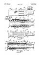
- FIG. 3is a side view of a crimp Joint according to the present invention.
- FIG. 4is a sectional view on an enlarged scale of the crimp joint of FIG. 3.
- a crimp joint formed in a fluid line systemis designated as 30 in FIGS. 3 and 4.
- Crimp joint 30is comprised of a flexible hose 32 secured to a rigid metal tube 34 by a crimped metal ferrule 36.
- Hose 32 and tube 34lead to remote (not shown) components in the fluid line system.
- the remote end of tube 34may be fastened to its mating component by a conventional, fixed-point method.
- the remote end of hose 32may be fastened to its mating component through use of a similarly crimped ferrule, or through some other type of conventional restraint.
- a thin layer or coating 38 of thermoplastic material(nylon preferred) is extruded over tube 34.
- a predetermined length of the plastic coatingis then removed or stripped from one end of tube 34 to define an uncoated or stem portion 40 of tube 34.
- the remote (not shown) end of tube 34is then cut to a predetermined finished length.
- Stem portion 40is specially formed to receive hose 32 with a configuration of beads or bumps. Stop bump 42 is formed adjacent to coated portion 38 of tube 34, and containment bump 44 is formed between stop bump 42 and end 46 of stem portion 40. After formation of bumps 42 and 44, end 46 is chamfered and stem portion 40 is deburred (if necessary).
- Hose 32is received over stem portion 40 of tube 34, with a confronting end 48 abutting stop bump 42.
- Hose 32has an interior plastic lining 50 (preferably teflon) surrounded by an exterior metal wire braiding 52.
- a thin layer or coating 54 of thermoplastic or thermoset materiali.e. polyester elastomer, nylon-based or silicone-based is extruded over metal braiding 52. The hose is cut to a predetermined length, and a portion of plastic coating 54 is removed or stripped from hose 32 to define an uncoated portion 56.
- Ferrule 36is hollow and extends between a small diameter end 58 and a large diameter end 60. End 60 is flared outward slightly. Three crimp portions are defined between ferrule ends 58 and 60. In order of increasing diameter (from small diameter end 58 towards large diameter end 60) they are: tube seal crimp portion 62, retention crimp portion 64, and hose seal crimp portion 66. An enlarged stop bump receptacle 68 is formed between crimp portions 62 and 64.
- Ferrule 36is installed over the hose/tube interface such that tube seal crimp portion 62 surrounds plastic coated portion 38 of tube 34, stop bump receptacle 68 receives stop bump 42, retention crimp portion 64 surrounds uncoated portion 56 of hose 32 and uncoated portion 40 of tube 34 between stop bump 42 and containment bump 44, and hose seal crimp portion 66 surrounds plastic coated portion 54 of hose 32.
- a crimping operationproduces retention crimp portion 64, tube seal crimp portion 62, and hose seal crimp portion 66.
- Retention crimp portion 64retains hose 32 on tube 34 between bumps 42 and 44. This central crimp provides direct contact between the interior of metal ferrule 36 and metal braid 52 of hose 32 which in turn provides a strong retention force between the tube and the hose.
- Tube seal crimp portion 62is located over plastic coated portion 38 of tube 34, and hose seal crimp portion 66 is located over coated portion 54 of hose 32.
- the application of crimp force around these end locationscreates sealed, plastic-to-metal contact areas at the end portions, or ingress points, of ferrule 36. These sealed contact areas prevent influx of corrosion-creating contamination and moisture into the joint, particularly into the critical retention crimp 64. Furthermore, the plastic-to-metal contact eliminates galvanic reactions at the environmentally exposed areas.
- the corrosion-resistant crimp joint 30 illustrated in FIGS. 3 and 4represents a significant improvement over the corrosion-prone prior art joint 10 illustrated in FIGS. 1 and 2.
- prior art joint 10metal-to-metal contact occurs over the entire length of ferrule 20 with metal hose braid 14. There are no means to prevent corrosion influx into the critical crimp interface.
- the present inventionaddresses corrosion resistance by eliminating metal-to-metal contact at environmentally exposed areas and by providing an effective seal through plastic-to-metal contact at ingress points.
Landscapes
- Engineering & Computer Science (AREA)
- General Engineering & Computer Science (AREA)
- Mechanical Engineering (AREA)
- Joints That Cut Off Fluids, And Hose Joints (AREA)
Abstract
Description
Claims (20)
Priority Applications (1)
| Application Number | Priority Date | Filing Date | Title |
|---|---|---|---|
| US08/404,517US5622394A (en) | 1995-03-15 | 1995-03-15 | Corrosion-resistant joint |
Applications Claiming Priority (1)
| Application Number | Priority Date | Filing Date | Title |
|---|---|---|---|
| US08/404,517US5622394A (en) | 1995-03-15 | 1995-03-15 | Corrosion-resistant joint |
Publications (1)
| Publication Number | Publication Date |
|---|---|
| US5622394Atrue US5622394A (en) | 1997-04-22 |
Family
ID=23599921
Family Applications (1)
| Application Number | Title | Priority Date | Filing Date |
|---|---|---|---|
| US08/404,517Expired - LifetimeUS5622394A (en) | 1995-03-15 | 1995-03-15 | Corrosion-resistant joint |
Country Status (1)
| Country | Link |
|---|---|
| US (1) | US5622394A (en) |
Cited By (29)
| Publication number | Priority date | Publication date | Assignee | Title |
|---|---|---|---|---|
| DE29815359U1 (en) | 1998-08-27 | 1998-11-19 | ITT Manufacturing Enterprises, Inc., Wilmington, Del. | Connection device for hoses |
| DE19802039A1 (en)* | 1998-01-21 | 1999-07-22 | Itt Mfg Enterprises Inc | Hose connection fitting |
| GB2336636A (en)* | 1998-04-22 | 1999-10-27 | Automotive Products Plc | Brake pipe assembly |
| US6000435A (en)* | 1997-12-22 | 1999-12-14 | Mcdonnell Douglas Corporation | Reinforced hose and retainer ring assembly |
| US6173995B1 (en) | 1998-02-04 | 2001-01-16 | Titeflex Corporation | Self-flaring, split bushing pipe fitting and hose assemblies employing same |
| US6422839B1 (en) | 1999-11-24 | 2002-07-23 | Visteon Global Technologies, Inc. | Corrosive resistant fuel pump |
| US6422609B1 (en)* | 1999-08-20 | 2002-07-23 | Itt Manufacturing Enterprises, Inc. | Fluid joint |
| US6447020B1 (en) | 1998-03-24 | 2002-09-10 | C. F. Gomma Usa, Inc. | High-pressure integral tube coupling arrangements |
| US20020144742A1 (en)* | 2001-04-05 | 2002-10-10 | Martucci Norman S. | Hose assembly and method of making same |
| EP1300622A1 (en)* | 2001-10-05 | 2003-04-09 | Dayco Fluid Technologies S.p.A. | A duct for feeding a fluid at high pressure |
| US20030184087A1 (en)* | 2002-03-29 | 2003-10-02 | Tokai Rubber Industries, Ltd. | Hose clamping structure |
| US20040155463A1 (en)* | 2003-02-07 | 2004-08-12 | Moner Ronald A. | Pre-assemblable, push-in fitting connection for corrugated tubing |
| US20040206443A1 (en)* | 2003-04-19 | 2004-10-21 | Degussa Ag - Intellectual Property Management | Ultrasound welding of plastics components |
| US20050040646A1 (en)* | 2001-01-12 | 2005-02-24 | Harco Industries, Inc. | Flexible hydraulic brake line assembly for motor vehicle wheels |
| US20050218196A1 (en)* | 2004-04-06 | 2005-10-06 | United Technolgies Corporation | Two tier brazing for joining copper tubes to manifolds |
| US20060016499A1 (en)* | 2003-09-05 | 2006-01-26 | Blanchard Ralph T | Flexible, kink resistant, fluid transfer hose construction |
| US20070029795A1 (en)* | 2005-08-04 | 2007-02-08 | Moner Ronald A | Pre-Assemblable, Push-In Fitting Connection for Corrugated Tubing |
| US20070051418A1 (en)* | 2005-09-02 | 2007-03-08 | Rowles Brian A | Multilayer tubes |
| US20070108765A1 (en)* | 2003-04-08 | 2007-05-17 | Sanoh Indutrial Co., Ltd. | Pipe connecting structure |
| US20070126232A1 (en)* | 2005-12-05 | 2007-06-07 | Itt Manufacturing Enterprises, Inc. | Fluid coupling with non-protective coated endform tip |
| US20080149212A1 (en)* | 2004-12-02 | 2008-06-26 | Jordi Relats | Protection Tube Which Is Resistant To High Temperatures |
| US20080168769A1 (en)* | 2007-01-17 | 2008-07-17 | International Engine Intellectual Property Company, Llc | Fluid tube assembly guide |
| US20080303277A1 (en)* | 2007-06-05 | 2008-12-11 | Tamotsu Yamashita | Non-bolt joint structure and method for producing non-bolt joint structure |
| WO2011069937A1 (en)* | 2009-12-08 | 2011-06-16 | Contitech Kühner Gmbh & Cie.Kg | Crimp coupling for a hose connection and method for producing a hose connection comprising a crimp coupling |
| US20180340640A1 (en)* | 2017-05-23 | 2018-11-29 | Dongguan Gateway Plastic And Hardware Lighting Co., Ltd. | Tube assembly |
| US20220003341A1 (en)* | 2020-07-01 | 2022-01-06 | Futaba Industrial Co., Ltd. | Pipe, spool forming die, and pipe manufacturing method |
| US20220034433A1 (en)* | 2018-09-21 | 2022-02-03 | Huizhou Hydro Caresys Medical Co., Ltd. | Pipe joint and method for using same |
| US11275217B2 (en)* | 2019-06-26 | 2022-03-15 | Senko Advanced Components, Inc. | Field installable fiber optic connector with crimp zones for unjacketed optical fibers |
| US20220105780A1 (en)* | 2019-02-15 | 2022-04-07 | Hanon Systems | Fluid pipe for a heating and air conditioning unit |
Citations (34)
| Publication number | Priority date | Publication date | Assignee | Title |
|---|---|---|---|---|
| US590258A (en)* | 1897-09-21 | Connecting hose to nipples | ||
| US2205347A (en)* | 1939-08-25 | 1940-06-18 | Albert E Dieterich | Hose clamp |
| US2268142A (en)* | 1939-09-27 | 1941-12-30 | Scovill Manufacturing Co | Coupling with collapsible nipple flange |
| US2374224A (en)* | 1941-04-22 | 1945-04-24 | Bowden Eng Ltd | Flexible hose coupling |
| US2374225A (en)* | 1941-10-04 | 1945-04-24 | Bowden Eng Ltd | Flexible hose coupling |
| US2384635A (en)* | 1945-09-11 | Flexible hose coupling | ||
| US2685458A (en)* | 1951-11-03 | 1954-08-03 | Ernest C Shaw | Coupling for hydraulic hose |
| US3462177A (en)* | 1967-07-31 | 1969-08-19 | Hewitt Robins Inc | Flexible hose and coupling therefor |
| US3484121A (en)* | 1966-09-26 | 1969-12-16 | Wayne E Quinton | Cannula extension and connector apparatus |
| US3501171A (en)* | 1967-07-10 | 1970-03-17 | Alfred Morton Baron | Connector assembly for fluid conduits |
| US3549180A (en)* | 1968-05-16 | 1970-12-22 | Scovill Manufacturing Co | Hose and hose coupling assembly |
| US3565116A (en)* | 1968-09-12 | 1971-02-23 | White Motor Corp | Safety hose and fitting assembly |
| US3711131A (en)* | 1970-02-25 | 1973-01-16 | Flextube Ltd | Hose end couplings |
| US3784236A (en)* | 1971-10-05 | 1974-01-08 | Robroy Ind | Fitting for flexible conduits |
| US3924883A (en)* | 1974-06-12 | 1975-12-09 | Weatherhead Co | Hose coupling |
| US4208067A (en)* | 1977-04-08 | 1980-06-17 | Pneumatiques, Caoutchouc Manufacture Et Plastiques Kleber-Colombes | Flexible hoses |
| US4279435A (en)* | 1973-04-10 | 1981-07-21 | Perfection Corporation | Gas riser apparatus |
| US4486034A (en)* | 1981-09-11 | 1984-12-04 | Rasmussen Gmbh | Sleeve coupling for hoses or the like |
| US4537183A (en)* | 1983-04-08 | 1985-08-27 | Mentor Corporation | Connector device for connecting elastic tubing of an implantable device |
| US4602808A (en)* | 1982-06-28 | 1986-07-29 | Dana Corporation | Protective routing sleeve for hose assembly |
| US4635972A (en)* | 1985-05-13 | 1987-01-13 | R. W. Lyall & Company, Inc. | Plastic pipe coupling apparatus and method of using same |
| US4664424A (en)* | 1982-11-12 | 1987-05-12 | Internationale Octrooi Maatschappij | Hose coupling |
| US4674719A (en)* | 1984-12-12 | 1987-06-23 | Hitachi Cable, Ltd. | Device for securing a brake hose at an intermediate portion thereof to an appropriate point in a vehicle body |
| US4775171A (en)* | 1987-04-06 | 1988-10-04 | Marshall Don J | High pressure field repair coupling |
| US4804212A (en)* | 1986-11-06 | 1989-02-14 | Stratoflex, Inc. | Crimped hose fitting |
| US4929236A (en)* | 1988-05-26 | 1990-05-29 | Shiley Infusaid, Inc. | Snap-lock fitting catheter for an implantable device |
| US4929002A (en)* | 1988-04-20 | 1990-05-29 | Rasmussen Gmbh | Device for coupling a hose to a pipe |
| US4932689A (en)* | 1989-07-28 | 1990-06-12 | Teleflex Incorporated | Hose fitting assembly |
| US4991876A (en)* | 1989-07-28 | 1991-02-12 | Euroflex, S.A. | Connector assembly for hot water heaters and other appliances |
| US5037142A (en)* | 1989-07-24 | 1991-08-06 | General Motors Corporation | Fluid line support and connector |
| US5044671A (en)* | 1990-06-21 | 1991-09-03 | S & H Fabricating And Engineering Incorporated | Swaged-type flexible hose coupling |
| US5090745A (en)* | 1990-08-23 | 1992-02-25 | Itt Corporation | Quick-connect connector for plastic tubes |
| US5255944A (en)* | 1991-05-30 | 1993-10-26 | Hutchinson | Coupler for a textile-reinforced rubber hose |
| US5275448A (en)* | 1991-09-10 | 1994-01-04 | Huron Products Industries, Inc. | Quick connect tubing connector and method of assembly |
- 1995
- 1995-03-15USUS08/404,517patent/US5622394A/ennot_activeExpired - Lifetime
Patent Citations (34)
| Publication number | Priority date | Publication date | Assignee | Title |
|---|---|---|---|---|
| US590258A (en)* | 1897-09-21 | Connecting hose to nipples | ||
| US2384635A (en)* | 1945-09-11 | Flexible hose coupling | ||
| US2205347A (en)* | 1939-08-25 | 1940-06-18 | Albert E Dieterich | Hose clamp |
| US2268142A (en)* | 1939-09-27 | 1941-12-30 | Scovill Manufacturing Co | Coupling with collapsible nipple flange |
| US2374224A (en)* | 1941-04-22 | 1945-04-24 | Bowden Eng Ltd | Flexible hose coupling |
| US2374225A (en)* | 1941-10-04 | 1945-04-24 | Bowden Eng Ltd | Flexible hose coupling |
| US2685458A (en)* | 1951-11-03 | 1954-08-03 | Ernest C Shaw | Coupling for hydraulic hose |
| US3484121A (en)* | 1966-09-26 | 1969-12-16 | Wayne E Quinton | Cannula extension and connector apparatus |
| US3501171A (en)* | 1967-07-10 | 1970-03-17 | Alfred Morton Baron | Connector assembly for fluid conduits |
| US3462177A (en)* | 1967-07-31 | 1969-08-19 | Hewitt Robins Inc | Flexible hose and coupling therefor |
| US3549180A (en)* | 1968-05-16 | 1970-12-22 | Scovill Manufacturing Co | Hose and hose coupling assembly |
| US3565116A (en)* | 1968-09-12 | 1971-02-23 | White Motor Corp | Safety hose and fitting assembly |
| US3711131A (en)* | 1970-02-25 | 1973-01-16 | Flextube Ltd | Hose end couplings |
| US3784236A (en)* | 1971-10-05 | 1974-01-08 | Robroy Ind | Fitting for flexible conduits |
| US4279435A (en)* | 1973-04-10 | 1981-07-21 | Perfection Corporation | Gas riser apparatus |
| US3924883A (en)* | 1974-06-12 | 1975-12-09 | Weatherhead Co | Hose coupling |
| US4208067A (en)* | 1977-04-08 | 1980-06-17 | Pneumatiques, Caoutchouc Manufacture Et Plastiques Kleber-Colombes | Flexible hoses |
| US4486034A (en)* | 1981-09-11 | 1984-12-04 | Rasmussen Gmbh | Sleeve coupling for hoses or the like |
| US4602808A (en)* | 1982-06-28 | 1986-07-29 | Dana Corporation | Protective routing sleeve for hose assembly |
| US4664424A (en)* | 1982-11-12 | 1987-05-12 | Internationale Octrooi Maatschappij | Hose coupling |
| US4537183A (en)* | 1983-04-08 | 1985-08-27 | Mentor Corporation | Connector device for connecting elastic tubing of an implantable device |
| US4674719A (en)* | 1984-12-12 | 1987-06-23 | Hitachi Cable, Ltd. | Device for securing a brake hose at an intermediate portion thereof to an appropriate point in a vehicle body |
| US4635972A (en)* | 1985-05-13 | 1987-01-13 | R. W. Lyall & Company, Inc. | Plastic pipe coupling apparatus and method of using same |
| US4804212A (en)* | 1986-11-06 | 1989-02-14 | Stratoflex, Inc. | Crimped hose fitting |
| US4775171A (en)* | 1987-04-06 | 1988-10-04 | Marshall Don J | High pressure field repair coupling |
| US4929002A (en)* | 1988-04-20 | 1990-05-29 | Rasmussen Gmbh | Device for coupling a hose to a pipe |
| US4929236A (en)* | 1988-05-26 | 1990-05-29 | Shiley Infusaid, Inc. | Snap-lock fitting catheter for an implantable device |
| US5037142A (en)* | 1989-07-24 | 1991-08-06 | General Motors Corporation | Fluid line support and connector |
| US4932689A (en)* | 1989-07-28 | 1990-06-12 | Teleflex Incorporated | Hose fitting assembly |
| US4991876A (en)* | 1989-07-28 | 1991-02-12 | Euroflex, S.A. | Connector assembly for hot water heaters and other appliances |
| US5044671A (en)* | 1990-06-21 | 1991-09-03 | S & H Fabricating And Engineering Incorporated | Swaged-type flexible hose coupling |
| US5090745A (en)* | 1990-08-23 | 1992-02-25 | Itt Corporation | Quick-connect connector for plastic tubes |
| US5255944A (en)* | 1991-05-30 | 1993-10-26 | Hutchinson | Coupler for a textile-reinforced rubber hose |
| US5275448A (en)* | 1991-09-10 | 1994-01-04 | Huron Products Industries, Inc. | Quick connect tubing connector and method of assembly |
Cited By (42)
| Publication number | Priority date | Publication date | Assignee | Title |
|---|---|---|---|---|
| US6000435A (en)* | 1997-12-22 | 1999-12-14 | Mcdonnell Douglas Corporation | Reinforced hose and retainer ring assembly |
| DE19802039A1 (en)* | 1998-01-21 | 1999-07-22 | Itt Mfg Enterprises Inc | Hose connection fitting |
| EP0931968A1 (en)* | 1998-01-21 | 1999-07-28 | Itt Manufacturing Enterprises, Inc. | Hose connector fitting |
| US6164704A (en)* | 1998-01-21 | 2000-12-26 | Itt Manufacturing Enterprises, Inc. | Hose fitting |
| US6173995B1 (en) | 1998-02-04 | 2001-01-16 | Titeflex Corporation | Self-flaring, split bushing pipe fitting and hose assemblies employing same |
| US6447020B1 (en) | 1998-03-24 | 2002-09-10 | C. F. Gomma Usa, Inc. | High-pressure integral tube coupling arrangements |
| GB2336636A (en)* | 1998-04-22 | 1999-10-27 | Automotive Products Plc | Brake pipe assembly |
| DE29815359U1 (en) | 1998-08-27 | 1998-11-19 | ITT Manufacturing Enterprises, Inc., Wilmington, Del. | Connection device for hoses |
| US6422609B1 (en)* | 1999-08-20 | 2002-07-23 | Itt Manufacturing Enterprises, Inc. | Fluid joint |
| US6422839B1 (en) | 1999-11-24 | 2002-07-23 | Visteon Global Technologies, Inc. | Corrosive resistant fuel pump |
| US20050040646A1 (en)* | 2001-01-12 | 2005-02-24 | Harco Industries, Inc. | Flexible hydraulic brake line assembly for motor vehicle wheels |
| US20020144742A1 (en)* | 2001-04-05 | 2002-10-10 | Martucci Norman S. | Hose assembly and method of making same |
| US6773038B2 (en) | 2001-10-05 | 2004-08-10 | Dayco Fluid Technologies S.P.A. | Duct for feeding a fluid at high pressure |
| EP1300622A1 (en)* | 2001-10-05 | 2003-04-09 | Dayco Fluid Technologies S.p.A. | A duct for feeding a fluid at high pressure |
| US20030184087A1 (en)* | 2002-03-29 | 2003-10-02 | Tokai Rubber Industries, Ltd. | Hose clamping structure |
| US6837524B2 (en)* | 2002-03-29 | 2005-01-04 | Tokai Rubber Industries, Ltd. | Hose clamping structure |
| US20040155463A1 (en)* | 2003-02-07 | 2004-08-12 | Moner Ronald A. | Pre-assemblable, push-in fitting connection for corrugated tubing |
| US6908114B2 (en) | 2003-02-07 | 2005-06-21 | Parker-Hannifin Corporation | Pre-assemblable, push-in fitting connection for corrugated tubing |
| US7452004B2 (en)* | 2003-04-08 | 2008-11-18 | Sanoh Industrial Co., Ltd. | Pipe connecting structure |
| US20070108765A1 (en)* | 2003-04-08 | 2007-05-17 | Sanoh Indutrial Co., Ltd. | Pipe connecting structure |
| US20040206443A1 (en)* | 2003-04-19 | 2004-10-21 | Degussa Ag - Intellectual Property Management | Ultrasound welding of plastics components |
| US7025842B2 (en)* | 2003-04-19 | 2006-04-11 | Degussa Ag | Ultrasound welding of plastics components |
| US20060016499A1 (en)* | 2003-09-05 | 2006-01-26 | Blanchard Ralph T | Flexible, kink resistant, fluid transfer hose construction |
| US7293689B2 (en)* | 2004-04-06 | 2007-11-13 | United Technologies Corporation | Two tier brazing for joining copper tubes to manifolds |
| US20050218196A1 (en)* | 2004-04-06 | 2005-10-06 | United Technolgies Corporation | Two tier brazing for joining copper tubes to manifolds |
| US20080149212A1 (en)* | 2004-12-02 | 2008-06-26 | Jordi Relats | Protection Tube Which Is Resistant To High Temperatures |
| US7690693B2 (en) | 2005-08-04 | 2010-04-06 | Parker-Hannifin Corporation | Pre-assemblable, push-in fitting connection for corrugated tubing |
| US20070029795A1 (en)* | 2005-08-04 | 2007-02-08 | Moner Ronald A | Pre-Assemblable, Push-In Fitting Connection for Corrugated Tubing |
| US20070051418A1 (en)* | 2005-09-02 | 2007-03-08 | Rowles Brian A | Multilayer tubes |
| US20070126232A1 (en)* | 2005-12-05 | 2007-06-07 | Itt Manufacturing Enterprises, Inc. | Fluid coupling with non-protective coated endform tip |
| US20080168769A1 (en)* | 2007-01-17 | 2008-07-17 | International Engine Intellectual Property Company, Llc | Fluid tube assembly guide |
| US8118331B2 (en)* | 2007-06-05 | 2012-02-21 | Suiken Co., Ltd. | Non-bolt joint structure and method for producing non-bolt joint structure |
| US20080303277A1 (en)* | 2007-06-05 | 2008-12-11 | Tamotsu Yamashita | Non-bolt joint structure and method for producing non-bolt joint structure |
| WO2011069937A1 (en)* | 2009-12-08 | 2011-06-16 | Contitech Kühner Gmbh & Cie.Kg | Crimp coupling for a hose connection and method for producing a hose connection comprising a crimp coupling |
| US20180340640A1 (en)* | 2017-05-23 | 2018-11-29 | Dongguan Gateway Plastic And Hardware Lighting Co., Ltd. | Tube assembly |
| US10704720B2 (en)* | 2017-05-23 | 2020-07-07 | Dongguan Gateway Plastic And Hardware Lighting Co., Ltd. | Tube assembly |
| US20220034433A1 (en)* | 2018-09-21 | 2022-02-03 | Huizhou Hydro Caresys Medical Co., Ltd. | Pipe joint and method for using same |
| US20220105780A1 (en)* | 2019-02-15 | 2022-04-07 | Hanon Systems | Fluid pipe for a heating and air conditioning unit |
| US12043084B2 (en)* | 2019-02-15 | 2024-07-23 | Hanon Systems | Fluid pipe for a heating and air conditioning unit |
| US11275217B2 (en)* | 2019-06-26 | 2022-03-15 | Senko Advanced Components, Inc. | Field installable fiber optic connector with crimp zones for unjacketed optical fibers |
| US20220003341A1 (en)* | 2020-07-01 | 2022-01-06 | Futaba Industrial Co., Ltd. | Pipe, spool forming die, and pipe manufacturing method |
| US12000507B2 (en)* | 2020-07-01 | 2024-06-04 | Futaba Industrial Co., Ltd. | Pipe, spool forming die, and pipe manufacturing method |
Similar Documents
| Publication | Publication Date | Title |
|---|---|---|
| US5622394A (en) | Corrosion-resistant joint | |
| US4669757A (en) | High pressure fluid conduit assembly | |
| US6447020B1 (en) | High-pressure integral tube coupling arrangements | |
| US5992898A (en) | Quick-connect assembly and method of manufacture | |
| US6688653B1 (en) | Fitting assembly for fluid and vapor connection | |
| US6131964A (en) | SAS fitting for tube and pipe connections | |
| US3858914A (en) | Transition pipe connection | |
| EP1992860B1 (en) | Non-serviceable fluid coupling | |
| JP2006516159A (en) | Fitting for fiber reinforced hose | |
| EP1207586A2 (en) | Connector for hard-line coaxial cable | |
| US4602808A (en) | Protective routing sleeve for hose assembly | |
| US5090745A (en) | Quick-connect connector for plastic tubes | |
| JPH1130369A (en) | Connecting structure of outside face resin covered small diametral metallic pipe | |
| EP0568032A1 (en) | Coupling for metal tubes | |
| EP1612466A1 (en) | Tube connection structure | |
| FR2738893A1 (en) | METHOD OF MAKING A BIT, TIP AND CONNECTOR PRODUCED BY THIS METHOD AND CIRCUIT COMPRISING SUCH A CONNECTOR | |
| CA2145619C (en) | Composite insulators and a process for producing the same | |
| US6598906B2 (en) | Fluid couplings | |
| CN222527038U (en) | A plastic top-pull pipe and a connection structure of the plastic top-pull pipe | |
| GB2122714A (en) | Protective routing sleeve for hose assemblies | |
| KR20030013476A (en) | Spin welded fluid connector using plastic coated metal tube | |
| JP4275229B2 (en) | Connection structure for small diameter resin tubes used for connectors for small diameter pipe connections | |
| US4858967A (en) | High pressure hose fitting and method for sealing high pressure hoses to fittings | |
| US7121591B2 (en) | Flexible metal hose assembly and method of making the same | |
| RU2095677C1 (en) | Electrically grounded flexible hose and method of its manufacture |
Legal Events
| Date | Code | Title | Description |
|---|---|---|---|
| AS | Assignment | Owner name:BUNDY CORPORATION, MICHIGAN Free format text:ASSIGNMENT OF ASSIGNORS INTEREST;ASSIGNORS:SOLES, DENNIS C.;BRAUCKMILLER, RAYMOND R.;REEL/FRAME:007389/0912 Effective date:19950307 | |
| STCF | Information on status: patent grant | Free format text:PATENTED CASE | |
| AS | Assignment | Owner name:TI GROUP AUTOMOTIVE SYSTEMS CORPORATION, MICHIGAN Free format text:CHANGE OF NAME;ASSIGNOR:BUNDY CORPORATION;REEL/FRAME:010859/0541 Effective date:19991012 | |
| FPAY | Fee payment | Year of fee payment:4 | |
| AS | Assignment | Owner name:TI GROUP AUTOMOTIVE SYSTEMS, LLC, MICHIGAN Free format text:MERGER;ASSIGNOR:TI GROUP AUTOMOTIVE SYSTEMS CORPORATION;REEL/FRAME:012407/0436 Effective date:20010625 | |
| FPAY | Fee payment | Year of fee payment:8 | |
| AS | Assignment | Owner name:JPMORGAN CHASE BANK, N.A., NEW YORK Free format text:SECURITY AGREEMENT;ASSIGNORS:HANIL USA, L.L.C.;TI AUTOMOTIVE, L.L.C.;TI GROUP AUTOMOTIVE SYSTEMS, L.L.C.;REEL/FRAME:019733/0933 Effective date:20070629 Owner name:JPMORGAN CHASE BANK, N.A.,NEW YORK Free format text:SECURITY AGREEMENT;ASSIGNORS:HANIL USA, L.L.C.;TI AUTOMOTIVE, L.L.C.;TI GROUP AUTOMOTIVE SYSTEMS, L.L.C.;REEL/FRAME:019733/0933 Effective date:20070629 | |
| FPAY | Fee payment | Year of fee payment:12 | |
| AS | Assignment | Owner name:WILMINGTON TRUST (LONDON) LIMITED,UNITED KINGDOM Free format text:ASSIGNMENT OF SECURITY INTEREST;ASSIGNOR:JP MORGAN CHASE BANK, N.A.;REEL/FRAME:024055/0633 Effective date:20100208 Owner name:WILMINGTON TRUST (LONDON) LIMITED, UNITED KINGDOM Free format text:ASSIGNMENT OF SECURITY INTEREST;ASSIGNOR:JP MORGAN CHASE BANK, N.A.;REEL/FRAME:024055/0633 Effective date:20100208 | |
| AS | Assignment | Owner name:CITIBANK N.A., DELAWARE Free format text:TERM PATENT SECURITY AGREEMENT;ASSIGNOR:TI GROUP AUTOMOTIVE SYSTEMS, L.L.C.;REEL/FRAME:024896/0057 Effective date:20100825 Owner name:TI GROUP AUTOMOTIVE SYSTEMS, L.L.C., MICHIGAN Free format text:RELEASE AND TERMINATION OF PATENT SECURITY INTEREST;ASSIGNOR:WILMINGTON TRUST (LONDON) LIMITED (AS SUCCESSOR IN INTEREST TO JP MORGAN CHASE BANK, N.A.);REEL/FRAME:024891/0671 Effective date:20100825 Owner name:HANIL USA, L.L.C., MICHIGAN Free format text:RELEASE AND TERMINATION OF PATENT SECURITY INTEREST;ASSIGNOR:WILMINGTON TRUST (LONDON) LIMITED (AS SUCCESSOR IN INTEREST TO JP MORGAN CHASE BANK, N.A.);REEL/FRAME:024891/0671 Effective date:20100825 Owner name:TI AUTOMOTIVE, L.L.C., MICHIGAN Free format text:RELEASE AND TERMINATION OF PATENT SECURITY INTEREST;ASSIGNOR:WILMINGTON TRUST (LONDON) LIMITED (AS SUCCESSOR IN INTEREST TO JP MORGAN CHASE BANK, N.A.);REEL/FRAME:024891/0671 Effective date:20100825 Owner name:CITIBANK N.A., DELAWARE Free format text:ABL PATENT SECURITY AGREEMENT;ASSIGNOR:TI GROUP AUTOMOTIVE SYSTEMS, L.L.C.;REEL/FRAME:024895/0956 Effective date:20100825 | |
| AS | Assignment | Owner name:TI GROUP AUTOMOTIVE SYSTEMS, L.L.C., MICHIGAN Free format text:RELEASE BY SECURED PARTY;ASSIGNOR:CITIBANK, N.A.;REEL/FRAME:027865/0016 Effective date:20120314 Owner name:JPMORGAN CHASE BANK, N.A., NEW YORK Free format text:SECURITY AGREEMENT;ASSIGNORS:TI GROUP AUTOMOTIVE SYSTEMS, L.L.C.;TI AUTOMOTIVE LIMITED;TI AUTOMOTIVE CANADA, INC.;AND OTHERS;REEL/FRAME:027864/0968 Effective date:20120314 | |
| AS | Assignment | Owner name:TI AUTOMOTIVE LIMITED, UNITED KINGDOM Free format text:TERMINATION AND RELEASE;ASSIGNOR:JPMORGAN CHASE BANK, N.A., AS ADMINISTRATIVE AGENT;REEL/FRAME:036013/0775 Effective date:20150630 Owner name:TI GROUP AUTOMOTIVE SYSTEMS S DE R.L. DE C.V., MEX Free format text:TERMINATION AND RELEASE;ASSIGNOR:JPMORGAN CHASE BANK, N.A., AS ADMINISTRATIVE AGENT;REEL/FRAME:036013/0775 Effective date:20150630 Owner name:TI AUTOMOTIVE, L.L.C., MICHIGAN Free format text:TERMINATION AND RELEASE;ASSIGNOR:JPMORGAN CHASE BANK, N.A., AS ADMINISTRATIVE AGENT;REEL/FRAME:036013/0775 Effective date:20150630 Owner name:HANIL USA L.L.C., ALABAMA Free format text:TERMINATION AND RELEASE;ASSIGNOR:JPMORGAN CHASE BANK, N.A., AS ADMINISTRATIVE AGENT;REEL/FRAME:036013/0775 Effective date:20150630 Owner name:TI GROUP AUTOMOTIVE SYSTEMS, L.L.C., MICHIGAN Free format text:TERMINATION AND RELEASE;ASSIGNOR:JPMORGAN CHASE BANK, N.A., AS ADMINISTRATIVE AGENT;REEL/FRAME:036013/0775 Effective date:20150630 Owner name:TI AUTOMOTIVE CANADA, INC., CANADA Free format text:TERMINATION AND RELEASE;ASSIGNOR:JPMORGAN CHASE BANK, N.A., AS ADMINISTRATIVE AGENT;REEL/FRAME:036013/0775 Effective date:20150630 Owner name:JPMORGAN CHASE BANK, N.A., AS THE COLLATERAL AGENT Free format text:SECURITY AGREEMENT;ASSIGNORS:TI GROUP AUTOMOTIVE SYSTEMS, L.L.C.;HANIL USA, L.L.C.;TI AUTOMOTIVE, L.L.C.;REEL/FRAME:036013/0666 Effective date:20150630 | |
| AS | Assignment | Owner name:MILLENIUM INDUSTRIES CORPORATION, MICHIGAN Free format text:RELEASE OF SECURITY INTEREST (REEL 036013, FRAME 0666);ASSIGNOR:JPMORGAN CHASE BANK, N.A., AS COLLATERAL AGENT;REEL/FRAME:070917/0957 Effective date:20250422 Owner name:TI AUTOMOTIVE, L.L.C., MICHIGAN Free format text:RELEASE OF SECURITY INTEREST (REEL 036013, FRAME 0666);ASSIGNOR:JPMORGAN CHASE BANK, N.A., AS COLLATERAL AGENT;REEL/FRAME:070917/0957 Effective date:20250422 Owner name:HANIL USA, L.L.C., ALABAMA Free format text:RELEASE OF SECURITY INTEREST (REEL 036013, FRAME 0666);ASSIGNOR:JPMORGAN CHASE BANK, N.A., AS COLLATERAL AGENT;REEL/FRAME:070917/0957 Effective date:20250422 Owner name:TI GROUP AUTOMOTIVE SYSTEMS, L.L.C., MICHIGAN Free format text:RELEASE OF SECURITY INTEREST (REEL 036013, FRAME 0666);ASSIGNOR:JPMORGAN CHASE BANK, N.A., AS COLLATERAL AGENT;REEL/FRAME:070917/0957 Effective date:20250422 |