US5621421A - Antenna and mounting device and system - Google Patents
Antenna and mounting device and systemDownload PDFInfo
- Publication number
- US5621421A US5621421AUS08/316,900US31690094AUS5621421AUS 5621421 AUS5621421 AUS 5621421AUS 31690094 AUS31690094 AUS 31690094AUS 5621421 AUS5621421 AUS 5621421A
- Authority
- US
- United States
- Prior art keywords
- antenna
- boom
- strut
- aircraft
- clamping
- Prior art date
- Legal status (The legal status is an assumption and is not a legal conclusion. Google has not performed a legal analysis and makes no representation as to the accuracy of the status listed.)
- Expired - Fee Related
Links
Images


Classifications
- B—PERFORMING OPERATIONS; TRANSPORTING
- B64—AIRCRAFT; AVIATION; COSMONAUTICS
- B64C—AEROPLANES; HELICOPTERS
- B64C1/00—Fuselages; Constructional features common to fuselages, wings, stabilising surfaces or the like
- B64C1/36—Fuselages; Constructional features common to fuselages, wings, stabilising surfaces or the like adapted to receive antennas or radomes
- H—ELECTRICITY
- H01—ELECTRIC ELEMENTS
- H01Q—ANTENNAS, i.e. RADIO AERIALS
- H01Q1/00—Details of, or arrangements associated with, antennas
- H01Q1/12—Supports; Mounting means
- H01Q1/1207—Supports; Mounting means for fastening a rigid aerial element
- H—ELECTRICITY
- H01—ELECTRIC ELEMENTS
- H01Q—ANTENNAS, i.e. RADIO AERIALS
- H01Q1/00—Details of, or arrangements associated with, antennas
- H01Q1/27—Adaptation for use in or on movable bodies
- H01Q1/28—Adaptation for use in or on aircraft, missiles, satellites, or balloons
- H01Q1/282—Modifying the aerodynamic properties of the vehicle, e.g. projecting type aerials
Definitions
- This inventionin general relates to handling radio signals on an aircraft and more particularly an antenna and mounting device assembly and a signal handling system using two of said assemblies preferably to receive radio signals remote from the aircraft.
- One of the most efficient methods for radio tracking far ranging animals equipped with radio beaconsis to use an aircraft.
- the aircraftTo perform aerial tracking the aircraft must be equipped with one or more antennas fitted to the airplane in such a manner as to comply with FAA airworthiness standards. It is important to comply with the regulations to avoid grounding of the aircraft by the FAA, to avoid violation and possible cancellation of insurance policies to both personnel and aircraft and to release liability obligations. Any externally mounted structure on an aircraft must be tested to ensure that the device does not interfere with aircraft controls, reduce the strength of the aircraft or adversely affect flight characteristics.
- an antenna and a mounting device assemblythat will fit on both the left and right sides of an aircraft, particularly an aircraft with a strut such as the Model 172 Cessna to handle and particularly receive signals transmitted remote from the aircraft.
- the antenna disclosedis of the Yagi type having a boom and suitable radiating elements fastened to the boom so as to provide a desirable signal reception pattern during flight.
- the mounting deviceincludes a first clamping bracket that fits against the wing strut and has a plurality of spaced straps that encircle the first clamping bracket and the strut for releasably gripping the strut. Spaced first and second arms extend from the first clamping bracket and are twisted relative to the longitudinal axis of each arm at a selected angle to orient the antenna relative to the horizontal and carry second clamping means including first and second antenna clamping brackets that clamp to the antenna
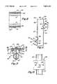
- FIG. 1is a front elevation showing a signal reception system including left and right side assemblies on an aircraft embodying features of the present invention.
- FIG. 2is a top plan view as seen along line 2--2 of FIG. 1 of the left side assembly.
- FIG. 3is a front elevation view of the left side assembly as seen along line 3--3 of FIG. 2.
- FIG. 4is an end elevational view of the folded dipole element mounted to the boom as seen along line 4--4 of FIG. 3.
- FIG. 5is a sectional view taken along line 5--5 of FIG. 2.
- FIG. 6is a sectional view taken along line 6--6 of FIG. 2.
- FIG. 7is a sectional view taken along line 7--7 of FIG. 2.
- FIG. 8is a sectional view taken along line 8--8 of FIG. 7.
- FIG. 9is a sectional view taken along line 9--9 of FIG. 2.
- FIG. 10is a sectional view taken along line 10--10 of FIG. 9.
- FIG. 11is a top plan view of the mounting device without the antenna and strut shown.
- FIG. 1there is shown a signal handling system for an aircraft 12 shown in schematic form as having a left side strut 13 and a right side strut 14.
- the signal handling system shownincludes a left side antenna and mounting device assembly 15 and a right side antenna and mounting device assembly 16.
- the antenna and mounting device assemblies 15 and 16are of the same construction and differ only in being constructed for left and right side mountings, respectively. A detailed description will now be made of the left side antenna and mounting device assembly 15.
- the antenna 21 shownis of the Yagi type and comprises a boom 22 (FIGS. 2, 3 and 5) made of a preselected length of preferably aluminum tubing. There are three active elements mounted to the boom 22.
- the first active element 24(FIGS. 1, 2 and 4) is the driven element, the second active element 25 is the director element and the third active element 26 is the reflector element.
- the driven element 24is a folded dipole including two parallel spaced conductive rods, 28, 29, preferably aluminum, connected at the ends by two curved end sections 31 and 32.
- the folded dipoleis matched for a 50 ohm receiving system by means of a half-wave balun phasing section 33 (FIG. 2) connected to the feed terminals.
- the folded dipole constructiontakes advantage of the additional mechanical strength and rigidity provided by having two parallel spaced rods.
- the driven element 24is mounted to the boom 22 by means of a first boom mounting device 37 (FIGS. 2 and 5) made of a nonconductive material.
- the mounting device 37includes a front mounting member 41 and a rear mounting member 42 (FIGS. 4 and 5) each of which are a single, solid, molded, plastic body.
- the front mounting member 41has an oblong base 44 with a semicircular recess 45 along a rear face to fit against and conform to the exterior surface of about half of the cross section of the boom 22.
- a raised portion 46is offset to one side and projects forwardly of base 44.
- a hole 47 (FIG. 6) in the raised portion 46 and base 44is provided through which the rod 29 extends and is rigidly fastened as by molding the rod in the molded body.
- a hole 48extends through the center of the base and a bolt fastener 49 extends through the hole 48 and an aligned hole 50 in the boom.
- the rear mounting member 42is substantially a mirror image of the front mounting member 41 having an oblong base 54 with a semi-circular recess 55 in the front face of the base that conforms to the exterior surface of the boom 22, a raised portion 56 offset to one side with a hole 57 through which the rod 28 extends and is rigidly fastened by molding.
- a hole 58 in the base 54is aligned with bolt hole 48 and the boom hole 50 through which the bolt fastener 49 extends.
- a nut 61 and washer 62are on the end of fastener 49 with the nut threading on external threads of the bolt to firmly clamp the front and rear mounting members 41 and 42 (FIG.
- the director element 25(FIGS. 2, 3 and 6) and the reflector element 26 are each a single, straight aluminum rod and each are mounted to the boom and electrically insulated therefrom as is element 24.
- Element 25is mounted to the boom by a nonconductive mounting member 65.
- Element 26is mounted to the boom by a nonconductive mounting member 66.
- Members 65 and 66are of the same construction so a description of one applies to both. Referring to member 65 it is a single, solid, molded, plastic body and shown to have an oblong base 67 with a semi-circular recess 68 on the rear face that fits against the boom 22 and encompasses about one half the cross section of the boom.
- An offset raised portion 69is offset to one side and extends forwardly of the base 67.
- a hole 71 in the raised portion and baseis provided through which element 25 extends and is rigidly fastened as by molding.
- a base hole 72extends through the center of the base.
- a bolt fastener 73extends through the base hole 72 and a hole 74 in the boom and is fastened thereto by a nut 75 threading on the fastener 73 with a washer 76 on the fastener between the nut and boom.
- a coaxial cable connector 77 of the BNC typefits on a plastic (PVC) cap 79 that is mounted on the end of the boom 22 and a coaxial cable 78 extends from the connector 77 to the cab of the airplane for electrically connecting the boom to equipment inside the airplane cab.
- the connector 77is electrically connected by an internal wire inside the boom (not shown) that connects to the feed terminals 34a and 35a (FIG. 4) so that energy transmitted through antenna element 24 is coupled to suitable equipment inside the cab.
- Each mounting device 81has a generally channel shaped strut clamping bracket 82 having a base 83 and spaced side walls 84 and 85 (FIGS. 2 and 7) extending away from the opposite sides of the base 83 with a cross section that is shaped to conform to and fit around the portion of the cross section of the strut 13 on which it is mounted.
- the side walls 84 and 85extend through an arc greater than 180 degrees so the bracket 82 has substantial frictional engagement with the strut.
- the bracket 82has three sets of aligned slots 86, 87 and 88 in the top edges of the side walls 84 and 85. These sets of slots are spaced from one another along the side walls, one at each end and one at an intermediate position midway between the ends.
- the mounting deviceis made from a flat plate, preferably rigid metal, having a rectangular body with the sets of slots 86, 87 and 88 formed in opposite side edges and the arms 94 and 95 described hereafter extending out in opposite directions at opposite ends, the plate being bent or shaped into the channel-shaped form shown particularly in FIG. 11 with the side walls 84 and 85 being parallel to one another.
- a fastening strap 91(FIGS. 2, 3, 7 and 8) fits in each set of slots, extends around the clamping bracket 82 and strut 13 and a clamp 92 at the ends of the strap is tightened to draw the strap down to firmly clamp the clamping bracket 82 to the strut 13.
- the mounting devicehas a pair of parallel spaced arms 94 and 95 (FIGS. 2, 3 and 11) that are twisted about their longitudinal axis in opposite directions so that they face in opposite directions. The angle of twist of each arm 94 and 95 designated W is about 47 degrees.
- a rectangular cushion or pad 89(FIGS. 3, 7 and 8) is shown fitted between the clamping bracket 82 and strut 13.
- Each of arms 94 and 95carries a boom clamping bracket 96 (FIGS. 9 and 11) which is a generally U-shaped member having a base 97 and a pair of parallel spaced side walls 98 and 99 extending away from opposite sides of the base 97 with a pair of aligned, semi-circular notches 101 (FIG. 9) in the top edge of each of the side walls to receive and conform to about one half of the cross section of the boom 22.
- the base 97is fastened to the arm 95 by two, spaced side bolts 103 on each side of the center of the bracket 96.
- a nut 104is threaded on each side bolt 103 with a washer 105 between the nut and base 97.
- a center bolt 107extends through a hole 108 in the boom, and holes in the center of the base 97 and arm 95.
- a nut 109threads on the center bolt with a washer 111 between the nut 109 and arm 95 so that each clamping bracket 96 is firmly clamped to the antenna boom 22.
- the active elements 24, 25 and 26are disposed substantially vertically or upright at an angle of 75 degrees to the horizontal.
- the armsare rotated along a longitudinal axis through a selected angle to compensate for the angle of the boom designated E (about 30 degrees) and positions the boom at a selected angle D (about 15 degrees) relative to the horizontal. This supports the antenna rearwardly of the strut on the aircraft.
Landscapes
- Engineering & Computer Science (AREA)
- Aviation & Aerospace Engineering (AREA)
- Physics & Mathematics (AREA)
- Remote Sensing (AREA)
- Mechanical Engineering (AREA)
- Fluid Mechanics (AREA)
- Astronomy & Astrophysics (AREA)
- General Physics & Mathematics (AREA)
- Aerials With Secondary Devices (AREA)
- Support Of Aerials (AREA)
Abstract
Description
This invention in general relates to handling radio signals on an aircraft and more particularly an antenna and mounting device assembly and a signal handling system using two of said assemblies preferably to receive radio signals remote from the aircraft.
One of the most efficient methods for radio tracking far ranging animals equipped with radio beacons is to use an aircraft. To perform aerial tracking the aircraft must be equipped with one or more antennas fitted to the airplane in such a manner as to comply with FAA airworthiness standards. It is important to comply with the regulations to avoid grounding of the aircraft by the FAA, to avoid violation and possible cancellation of insurance policies to both personnel and aircraft and to release liability obligations. Any externally mounted structure on an aircraft must be tested to ensure that the device does not interfere with aircraft controls, reduce the strength of the aircraft or adversely affect flight characteristics.
An antenna mounted externally of an aircraft is disclosed in Bolljahn Ser. No. 2,505,751 having an antenna made of thin, flat, metal strips affixed to the ground plane by four angle pieces. Ganz Ser. No. 4,336,543 discloses an electronically scanned antenna system having a linear array of Yagi type endfire elements on the wing of an aircraft.
In accordance with the present invention, there is provided an antenna and a mounting device assembly that will fit on both the left and right sides of an aircraft, particularly an aircraft with a strut such as the Model 172 Cessna to handle and particularly receive signals transmitted remote from the aircraft. The antenna disclosed is of the Yagi type having a boom and suitable radiating elements fastened to the boom so as to provide a desirable signal reception pattern during flight. The mounting device includes a first clamping bracket that fits against the wing strut and has a plurality of spaced straps that encircle the first clamping bracket and the strut for releasably gripping the strut. Spaced first and second arms extend from the first clamping bracket and are twisted relative to the longitudinal axis of each arm at a selected angle to orient the antenna relative to the horizontal and carry second clamping means including first and second antenna clamping brackets that clamp to the antenna
Details of this invention are described in connection with the accompanying drawings which like parts bear similar reference numerals in which:
FIG. 1 is a front elevation showing a signal reception system including left and right side assemblies on an aircraft embodying features of the present invention.
FIG. 2 is a top plan view as seen alongline 2--2 of FIG. 1 of the left side assembly.
FIG. 3 is a front elevation view of the left side assembly as seen along line 3--3 of FIG. 2.
FIG. 4 is an end elevational view of the folded dipole element mounted to the boom as seen alongline 4--4 of FIG. 3.
FIG. 5 is a sectional view taken alongline 5--5 of FIG. 2.
FIG. 6 is a sectional view taken alongline 6--6 of FIG. 2.
FIG. 7 is a sectional view taken along line 7--7 of FIG. 2.
FIG. 8 is a sectional view taken along line 8--8 of FIG. 7.
FIG. 9 is a sectional view taken alongline 9--9 of FIG. 2.
FIG. 10 is a sectional view taken alongline 10--10 of FIG. 9.
FIG. 11 is a top plan view of the mounting device without the antenna and strut shown.
Referring now to FIG. 1 there is shown a signal handling system for anaircraft 12 shown in schematic form as having aleft side strut 13 and aright side strut 14. The signal handling system shown includes a left side antenna and mountingdevice assembly 15 and a right side antenna and mountingdevice assembly 16. The antenna and mountingdevice assemblies device assembly 15.
Theantenna 21 shown is of the Yagi type and comprises a boom 22 (FIGS. 2, 3 and 5) made of a preselected length of preferably aluminum tubing. There are three active elements mounted to theboom 22. The first active element 24 (FIGS. 1, 2 and 4) is the driven element, the secondactive element 25 is the director element and the thirdactive element 26 is the reflector element. The drivenelement 24 is a folded dipole including two parallel spaced conductive rods, 28, 29, preferably aluminum, connected at the ends by twocurved end sections 31 and 32. There is a gap orspace 36 between theends rod 29 which are the feed ends of the drivenelement 24. Feed ends 34 and 35 are connected to feedterminals
The folded dipole is matched for a 50 ohm receiving system by means of a half-wave balun phasing section 33 (FIG. 2) connected to the feed terminals. The folded dipole construction takes advantage of the additional mechanical strength and rigidity provided by having two parallel spaced rods.
The drivenelement 24 is mounted to theboom 22 by means of a first boom mounting device 37 (FIGS. 2 and 5) made of a nonconductive material. The mountingdevice 37 includes a front mountingmember 41 and a rear mounting member 42 (FIGS. 4 and 5) each of which are a single, solid, molded, plastic body. The front mountingmember 41 has anoblong base 44 with a semicircular recess 45 along a rear face to fit against and conform to the exterior surface of about half of the cross section of theboom 22. A raisedportion 46 is offset to one side and projects forwardly ofbase 44. A hole 47 (FIG. 6) in the raisedportion 46 andbase 44 is provided through which therod 29 extends and is rigidly fastened as by molding the rod in the molded body. Ahole 48 extends through the center of the base and abolt fastener 49 extends through thehole 48 and an alignedhole 50 in the boom.
Therear mounting member 42 is substantially a mirror image of the front mountingmember 41 having anoblong base 54 with asemi-circular recess 55 in the front face of the base that conforms to the exterior surface of theboom 22, a raisedportion 56 offset to one side with ahole 57 through which therod 28 extends and is rigidly fastened by molding. Ahole 58 in thebase 54 is aligned withbolt hole 48 and theboom hole 50 through which thebolt fastener 49 extends. Anut 61 andwasher 62 are on the end offastener 49 with the nut threading on external threads of the bolt to firmly clamp the front and rear mountingmembers 41 and 42 (FIG. 4) against the boom by forces applied from opposite directions toward the center of the boom with the mountingdevice 37 functioning to electrically insulate the drivenelement 24 from the boom. The ends 34 and 35 of the element are shown clamped between the front and rear mountingmembers feed terminals member 41.
The director element 25 (FIGS. 2, 3 and 6) and thereflector element 26 are each a single, straight aluminum rod and each are mounted to the boom and electrically insulated therefrom as iselement 24.Element 25 is mounted to the boom by anonconductive mounting member 65.Element 26 is mounted to the boom by anonconductive mounting member 66.Members member 65 it is a single, solid, molded, plastic body and shown to have anoblong base 67 with asemi-circular recess 68 on the rear face that fits against theboom 22 and encompasses about one half the cross section of the boom. An offset raisedportion 69 is offset to one side and extends forwardly of thebase 67. A hole 71 in the raised portion and base is provided through whichelement 25 extends and is rigidly fastened as by molding. Abase hole 72 extends through the center of the base. Abolt fastener 73 extends through thebase hole 72 and ahole 74 in the boom and is fastened thereto by anut 75 threading on thefastener 73 with awasher 76 on the fastener between the nut and boom.
Acoaxial cable connector 77 of the BNC type (FIG. 2) fits on a plastic (PVC)cap 79 that is mounted on the end of theboom 22 and acoaxial cable 78 extends from theconnector 77 to the cab of the airplane for electrically connecting the boom to equipment inside the airplane cab. Theconnector 77 is electrically connected by an internal wire inside the boom (not shown) that connects to thefeed terminals antenna element 24 is coupled to suitable equipment inside the cab.
Each mountingdevice 81 has a generally channel shapedstrut clamping bracket 82 having a base 83 and spacedside walls 84 and 85 (FIGS. 2 and 7) extending away from the opposite sides of the base 83 with a cross section that is shaped to conform to and fit around the portion of the cross section of thestrut 13 on which it is mounted. Theside walls bracket 82 has substantial frictional engagement with the strut. Thebracket 82 has three sets of alignedslots side walls slots arms side walls
A fastening strap 91 (FIGS. 2, 3, 7 and 8) fits in each set of slots, extends around the clampingbracket 82 and strut 13 and aclamp 92 at the ends of the strap is tightened to draw the strap down to firmly clamp the clampingbracket 82 to thestrut 13. The mounting device has a pair of parallel spacedarms 94 and 95 (FIGS. 2, 3 and 11) that are twisted about their longitudinal axis in opposite directions so that they face in opposite directions. The angle of twist of eacharm bracket 82 andstrut 13.
Each ofarms side walls boom 22. Thebase 97 is fastened to thearm 95 by two, spacedside bolts 103 on each side of the center of thebracket 96. Anut 104 is threaded on eachside bolt 103 with awasher 105 between the nut andbase 97. Acenter bolt 107 extends through ahole 108 in the boom, and holes in the center of thebase 97 andarm 95. Anut 109 threads on the center bolt with a washer 111 between thenut 109 andarm 95 so that each clampingbracket 96 is firmly clamped to theantenna boom 22.
Theactive elements
The equation for the calculation of the separation distance designated S for the arms of the mountingdevice 81 relative to the angle and thickness parameters shown in FIG. 3 is as follows: ##EQU1## where,
T--thickness ofstrut 13
B--diameter ofantenna boom 22
E--elevation angle ofstrut 13
D--depression angle ofboom 22
S--separation distance forarms
Although the present invention has been described with a certain degree of particularity, it is understood that the present disclosure has been made by way of example and that changes in details of structure may be made without departing from the spirit thereof.
Claims (21)
1. A mounting device for mounting an antenna to an aircraft for handling radio signals during flight, said device comprising:
first clamping means including an aircraft clamping bracket for gripping an external portion of a strut of an aircraft,
arm means extending out from said first clamping means and having opposite ends, said first clamping means at one of said ends, said arm means including a pair of spaced rigid arms that are twisted along a longitudinal axis in opposite directions through preselected angles to be oriented relative to said first clamping means at a selected fixed angle relative to an axis normal to said first clamping means for positioning said antenna relative to said strut at a selected separation distance from the aircraft and at a preselected limed angle of elevation to the horizontal, and
second clamping means at the other end of said arm means opposite said first clamping means for gripping said antenna.
2. A mounting device for mounting an antenna to an aircraft for handling radio signals during flight, said device comprising:
first clamping means including an aircraft clamping bracket for gripping an external portion of a strut of an aircraft,
arm means extending out from said first clamping means and having opposite ends, said first clamping means at one of said ends, said arm means oriented relative to said first clamping means at a selected angle relative to an axis normal to said first clamping means for positioning said antenna relative to said strut at a selected separation distance from the aircraft and at a preselected angle of elevation to the horizontal, said arm means including a pair of spaced arms that are twisted along a longitudinal axis in opposite directions through preselected angles, and
second clamping means at the other end of said arm means opposite said first clamping means for gripping said antenna, said second clamping means including a pair of second clamping brackets that are disposed by said spaced arms in oppositely facing directions.
3. A mounting device as set forth in claim 2 wherein said aircraft clamping bracket is a generally U-shaped member having a base and spaced side walls extending away from opposite sides of said base.
4. A mounting device as set forth in claim 2 wherein the angle of twist is about 47 degrees.
5. A mounting device as set forth in claim 2 wherein said second clamping means includes a pair of second clamping brackets that fit against and are clamped to said antenna.
6. A mounting device for mounting an antenna having a boom and a plurality of active elements to a wing strut of an aircraft for aerial reception of radio signals by the antenna during flight, said device comprising:
first clamping means including a strut clamping bracket having a base and spaced side walls extending away from said base, said first clamp means being sized to fit around a portion of an aircraft strut around which strap means extend for gripping said strut,
arm means including a pair of spaced first and second arms transverse to and extending out from said first clamping means, said first and second arms each having opposite ends, said first clamping means at one of said ends, said arms being twisted along a longitudinal axis in opposite directions through a preselected angle for positioning said boom relative to said strut at a selected separation distance from the aircraft and at a preselected angle of elevation to the horizontal, and
second clamping means including a pair of second antenna clamping brackets fastened at the other ends of said first and second arms, respectively, for gripping said antenna.
7. A mounting device as set forth in claim 6 wherein said strut clamping bracket is a generally U-shaped member having a base and spaced side walls extending away from opposite sides of said base and wherein said spaced side walls have a plurality of spaced sets of aligned slots in the top edges at intermediate and end positions.
8. A mounting device as set forth in claim 7 wherein said strap means includes a strap disposed in each of said sets of aligned slots, each strap having a clamp to selectively tighten said strap around said base and side walls and wing strut.
9. A mounting device as set forth in claim 6 wherein said each of said second antenna clamping brackets includes a generally U-shaped member having a base and spaced side walls extending away from opposite sides of said base, said side walls having a plurality of notches shaped to conform to and receive a portion of the cross section of the boom, and an opposite clamping bracket with fastening bolts clamping each antenna clamping bracket toward the opposite antenna clamping bracket and against the antenna.
10. An antenna and mounting device assembly for an in flight aircraft comprising:
an antenna,
a mounting device for fastening said antenna to an external portion of a strut of an aircraft, said mounting device including
first clamping means including an aircraft clamping bracket shaped to fit around an external portion of an aircraft for gripping said external portion,
arm means extending out from said first clamping means and having opposite ends, said first clamping means at one of said ends, said arm means including a pair of rigid spaced arms that are twisted along a longitudinal axis in opposite directions through preselected angles to be oriented relative to an axis normal to said first clamping means at a selected fixed angle for positioning said antenna relative to said strut at a selected separation distance from the aircraft and at a preselected fixed angle of elevation to the horizontal, and
second clamping means at the other end of said arm means opposite said first clamping means for gripping said antenna.
11. An assembly as set forth in claim 10 wherein said antenna is of the Yagi type having a boom in the form of a length of conductive tubing, a driven element mounted between the ends of the boom, a director element mounted at one end of the boom and a reflector element mounted at the other end of the boom.
12. An assembly as set forth in claim 11 wherein said driven element is a folded dipole including two parallel spaced conductive rods connected at the ends by two curved conductive end sections, an intermediate section of one of said conductive rods being separated to form spaced ends to provide the feed ends for said driven element.
13. An antenna and mounting device assembly for an in flight aircraft comprising:
an antenna, said antenna being of the Yagi type having a boom in the form of a length of conductive tubing, a driven element mounted between the ends of the boom, a director element mounted at one end of the boom and a reflector element mounted at the other end of the boom,
a mounting device for fastening said antenna to an external portion of a strut of an aircraft, said mounting device including
first clamping means including an aircraft clamping bracket shaped to fit around an external portion of an aircraft for gripping said external portion,
arm means extending out from said first clamping means and having opposite ends, said first clamping means at one of said ends, said arm means oriented relative to an axis normal to said first clamping means for positioning said antenna relative to said strut at a selected separation distance from the aircraft and at a preselected angle of elevation to the horizontal,
second clamping means at the other end of said arm means opposite said first clamping means for gripping said antenna, and
a mounting member for mounting each of said driven, director and reflector elements to said boom, each mounting member being made of a nonconductive material having an oblong base with a recess shaped to conform to a portion of the cross section of said boom to fit against said boom, an offset portion through which an associated element extends and is rigidly secured and a hole through which a bolt fastener extends to which a nut is threaded to clamp said mounting member to said boom.
14. An assembly as set forth in claim 13 wherein said mounting member is a molded material and each said element is molded in said molded material.
15. An assembly as set forth in claim 13 wherein each of said driven, director and reflector elements having two parallel spaced rods, there being a pair of said mounting members for each of said elements with one of said rods of each pair affixed to one of said mounting members of each pair, each pair of mounting members having aligned holes and bolt fasteners extending through each pair of said mounting members with nuts on said bolt fasteners to clamp said mounting members against said boom.
16. An antenna and mounting device assembly for an in flight aircraft having a wing strut comprising:
an antenna having a boom and a plurality of active elements each mounted to the boom by a mounting member for receiving radio signals,
a mounting device for fastening said antenna to a wing strut of an aircraft, said mounting device including
first clamping means including a strut clamping bracket having a base and spaced side walls sized and shaped to fit around a portion of an aircraft strut around which strap means extend for gripping said strut,
arm means including a pair of spaced first and second arms transverse to and extending out from said first clamping means for positioning said antenna relative to said strut, and
second clamping means including a pair of first and second antenna clamping brackets fastened at the ends of said first and second arms respectively, for gripping said antenna,
whereby said antenna will receive radio signals during flight of said aircraft.
17. An assembly as set forth in claim 16 that is constructed with dimensions substantially according to the equation ##EQU2## wherein T is the thickness of said strut, B is the diameter of said boom,
E is the elevation angle of said strut,
D is the depression angle of said boom, and
S is the separation distance for said arms.
18. An assembly as set forth in claim 16 wherein said side walls extend through an arc greater than 180 degrees to firmly secure said mounting device to said strut.
19. An aerial signal reception system for an in flight aircraft having a left side and a right side comprising:
a left side antenna and mounting device assembly mounted to a left side of the aircraft,
a right side antenna and mounting device assembly mounted to a right side of the aircraft,
each said antenna including
a boom to which are attached active elements, the active elements including a folded dipole driven element clamped to the boom intermediate the ends of the boom, a director element clamped to the boom at one end and a reflector element clamped to the boom at the other end,
each said mounting device including
first clamping means including a strut clamping bracket shaped to fit around an external portion of an aircraft around which strap means extend for gripping said external portion,
arm means including a pair of spaced first and second arms transverse to and extending out from said first clamping means, and
second clamping means including a pair of first and second antenna clamping brackets fastened to said first and second arms, respectively, for gripping said antenna to position said antenna relative to said strut for aerial reception of radio signals during flight.
20. An aerial signal reception system as set forth in claim 19 wherein said angle of elevation of said strut to the horizontal is about 30 degrees and said angle of depression of said boom to the horizontal is about 15 degrees.
21. An external aerial signal reception system for an in flight aircraft having a left side wing strut and a right side wing strut comprising:
a left side antenna and mounting device assembly mounted to a left side wing strut,
a right side antenna and mounting device assembly mounted to a right side wing strut,
each said antenna including
a boom to which are attached active elements, the active elements including a folded dipole driven element clamped to the boom intermediate the ends of the boom, a director element clamped to the boom at one end and a reflector element clamped to the boom at the other end,
each said mounting device including
first clamping means including a strut clamping bracket having a base wall and spaced side walls sized and shaped to fit around a portion of an aircraft strut around which strap means extend for gripping said strut,
arm means including a pair of spaced first and second arms transverse to and extending out from said first clamping means, and
second clamping means including a pair of first and second antenna clamping brackets fastened to said first and second arms, respectively, for gripping said antenna to position said antenna relative to said strut for aerial reception of radio signals during flight.
Priority Applications (1)
| Application Number | Priority Date | Filing Date | Title |
|---|---|---|---|
| US08/316,900US5621421A (en) | 1994-10-03 | 1994-10-03 | Antenna and mounting device and system |
Applications Claiming Priority (1)
| Application Number | Priority Date | Filing Date | Title |
|---|---|---|---|
| US08/316,900US5621421A (en) | 1994-10-03 | 1994-10-03 | Antenna and mounting device and system |
Publications (1)
| Publication Number | Publication Date |
|---|---|
| US5621421Atrue US5621421A (en) | 1997-04-15 |
Family
ID=23231200
Family Applications (1)
| Application Number | Title | Priority Date | Filing Date |
|---|---|---|---|
| US08/316,900Expired - Fee RelatedUS5621421A (en) | 1994-10-03 | 1994-10-03 | Antenna and mounting device and system |
Country Status (1)
| Country | Link |
|---|---|
| US (1) | US5621421A (en) |
Cited By (143)
| Publication number | Priority date | Publication date | Assignee | Title |
|---|---|---|---|---|
| US6111553A (en)* | 1997-10-07 | 2000-08-29 | Steenbuck; Wendel F. | Adjustable antenna bracket |
| US20060166628A1 (en)* | 2005-01-24 | 2006-07-27 | Sikorsky Aircraft Corporation | Dynamic antenna allocation system |
| US8860617B1 (en) | 2011-07-08 | 2014-10-14 | Trivec-Avant Corporation | Multiband embedded antenna |
| US9116239B1 (en)* | 2013-01-14 | 2015-08-25 | Rockwell Collins, Inc. | Low range altimeter antenna |
| US9608740B2 (en) | 2015-07-15 | 2017-03-28 | At&T Intellectual Property I, L.P. | Method and apparatus for launching a wave mode that mitigates interference |
| US9640850B2 (en) | 2015-06-25 | 2017-05-02 | At&T Intellectual Property I, L.P. | Methods and apparatus for inducing a non-fundamental wave mode on a transmission medium |
| US9667317B2 (en) | 2015-06-15 | 2017-05-30 | At&T Intellectual Property I, L.P. | Method and apparatus for providing security using network traffic adjustments |
| US9674711B2 (en) | 2013-11-06 | 2017-06-06 | At&T Intellectual Property I, L.P. | Surface-wave communications and methods thereof |
| US9685992B2 (en) | 2014-10-03 | 2017-06-20 | At&T Intellectual Property I, L.P. | Circuit panel network and methods thereof |
| US9705561B2 (en) | 2015-04-24 | 2017-07-11 | At&T Intellectual Property I, L.P. | Directional coupling device and methods for use therewith |
| US9705610B2 (en) | 2014-10-21 | 2017-07-11 | At&T Intellectual Property I, L.P. | Transmission device with impairment compensation and methods for use therewith |
| US9722318B2 (en) | 2015-07-14 | 2017-08-01 | At&T Intellectual Property I, L.P. | Method and apparatus for coupling an antenna to a device |
| US9729197B2 (en) | 2015-10-01 | 2017-08-08 | At&T Intellectual Property I, L.P. | Method and apparatus for communicating network management traffic over a network |
| US9735833B2 (en) | 2015-07-31 | 2017-08-15 | At&T Intellectual Property I, L.P. | Method and apparatus for communications management in a neighborhood network |
| US9742462B2 (en) | 2014-12-04 | 2017-08-22 | At&T Intellectual Property I, L.P. | Transmission medium and communication interfaces and methods for use therewith |
| US9742521B2 (en) | 2014-11-20 | 2017-08-22 | At&T Intellectual Property I, L.P. | Transmission device with mode division multiplexing and methods for use therewith |
| US9748626B2 (en) | 2015-05-14 | 2017-08-29 | At&T Intellectual Property I, L.P. | Plurality of cables having different cross-sectional shapes which are bundled together to form a transmission medium |
| US9749053B2 (en) | 2015-07-23 | 2017-08-29 | At&T Intellectual Property I, L.P. | Node device, repeater and methods for use therewith |
| US9749013B2 (en) | 2015-03-17 | 2017-08-29 | At&T Intellectual Property I, L.P. | Method and apparatus for reducing attenuation of electromagnetic waves guided by a transmission medium |
| US9762289B2 (en) | 2014-10-14 | 2017-09-12 | At&T Intellectual Property I, L.P. | Method and apparatus for transmitting or receiving signals in a transportation system |
| US9769020B2 (en) | 2014-10-21 | 2017-09-19 | At&T Intellectual Property I, L.P. | Method and apparatus for responding to events affecting communications in a communication network |
| US9768833B2 (en) | 2014-09-15 | 2017-09-19 | At&T Intellectual Property I, L.P. | Method and apparatus for sensing a condition in a transmission medium of electromagnetic waves |
| US9769128B2 (en) | 2015-09-28 | 2017-09-19 | At&T Intellectual Property I, L.P. | Method and apparatus for encryption of communications over a network |
| US9780834B2 (en) | 2014-10-21 | 2017-10-03 | At&T Intellectual Property I, L.P. | Method and apparatus for transmitting electromagnetic waves |
| US9788326B2 (en) | 2012-12-05 | 2017-10-10 | At&T Intellectual Property I, L.P. | Backhaul link for distributed antenna system |
| US9787412B2 (en) | 2015-06-25 | 2017-10-10 | At&T Intellectual Property I, L.P. | Methods and apparatus for inducing a fundamental wave mode on a transmission medium |
| US9793955B2 (en) | 2015-04-24 | 2017-10-17 | At&T Intellectual Property I, Lp | Passive electrical coupling device and methods for use therewith |
| US9793954B2 (en) | 2015-04-28 | 2017-10-17 | At&T Intellectual Property I, L.P. | Magnetic coupling device and methods for use therewith |
| US9793951B2 (en) | 2015-07-15 | 2017-10-17 | At&T Intellectual Property I, L.P. | Method and apparatus for launching a wave mode that mitigates interference |
| US9800327B2 (en) | 2014-11-20 | 2017-10-24 | At&T Intellectual Property I, L.P. | Apparatus for controlling operations of a communication device and methods thereof |
| US9820146B2 (en) | 2015-06-12 | 2017-11-14 | At&T Intellectual Property I, L.P. | Method and apparatus for authentication and identity management of communicating devices |
| US9838896B1 (en) | 2016-12-09 | 2017-12-05 | At&T Intellectual Property I, L.P. | Method and apparatus for assessing network coverage |
| US9838078B2 (en) | 2015-07-31 | 2017-12-05 | At&T Intellectual Property I, L.P. | Method and apparatus for exchanging communication signals |
| US9847850B2 (en) | 2014-10-14 | 2017-12-19 | At&T Intellectual Property I, L.P. | Method and apparatus for adjusting a mode of communication in a communication network |
| US9847566B2 (en) | 2015-07-14 | 2017-12-19 | At&T Intellectual Property I, L.P. | Method and apparatus for adjusting a field of a signal to mitigate interference |
| US9853342B2 (en) | 2015-07-14 | 2017-12-26 | At&T Intellectual Property I, L.P. | Dielectric transmission medium connector and methods for use therewith |
| US9860075B1 (en) | 2016-08-26 | 2018-01-02 | At&T Intellectual Property I, L.P. | Method and communication node for broadband distribution |
| US9866309B2 (en) | 2015-06-03 | 2018-01-09 | At&T Intellectual Property I, Lp | Host node device and methods for use therewith |
| US9865911B2 (en) | 2015-06-25 | 2018-01-09 | At&T Intellectual Property I, L.P. | Waveguide system for slot radiating first electromagnetic waves that are combined into a non-fundamental wave mode second electromagnetic wave on a transmission medium |
| US9866276B2 (en) | 2014-10-10 | 2018-01-09 | At&T Intellectual Property I, L.P. | Method and apparatus for arranging communication sessions in a communication system |
| US9871283B2 (en) | 2015-07-23 | 2018-01-16 | At&T Intellectual Property I, Lp | Transmission medium having a dielectric core comprised of plural members connected by a ball and socket configuration |
| US9871558B2 (en) | 2014-10-21 | 2018-01-16 | At&T Intellectual Property I, L.P. | Guided-wave transmission device and methods for use therewith |
| US9871282B2 (en) | 2015-05-14 | 2018-01-16 | At&T Intellectual Property I, L.P. | At least one transmission medium having a dielectric surface that is covered at least in part by a second dielectric |
| US9876605B1 (en) | 2016-10-21 | 2018-01-23 | At&T Intellectual Property I, L.P. | Launcher and coupling system to support desired guided wave mode |
| US9876571B2 (en) | 2015-02-20 | 2018-01-23 | At&T Intellectual Property I, Lp | Guided-wave transmission device with non-fundamental mode propagation and methods for use therewith |
| US9876264B2 (en) | 2015-10-02 | 2018-01-23 | At&T Intellectual Property I, Lp | Communication system, guided wave switch and methods for use therewith |
| US9882257B2 (en) | 2015-07-14 | 2018-01-30 | At&T Intellectual Property I, L.P. | Method and apparatus for launching a wave mode that mitigates interference |
| US9887447B2 (en) | 2015-05-14 | 2018-02-06 | At&T Intellectual Property I, L.P. | Transmission medium having multiple cores and methods for use therewith |
| US9893795B1 (en) | 2016-12-07 | 2018-02-13 | At&T Intellectual Property I, Lp | Method and repeater for broadband distribution |
| US9906269B2 (en) | 2014-09-17 | 2018-02-27 | At&T Intellectual Property I, L.P. | Monitoring and mitigating conditions in a communication network |
| US9913139B2 (en) | 2015-06-09 | 2018-03-06 | At&T Intellectual Property I, L.P. | Signal fingerprinting for authentication of communicating devices |
| US9912419B1 (en) | 2016-08-24 | 2018-03-06 | At&T Intellectual Property I, L.P. | Method and apparatus for managing a fault in a distributed antenna system |
| US9912382B2 (en) | 2015-06-03 | 2018-03-06 | At&T Intellectual Property I, Lp | Network termination and methods for use therewith |
| US9912027B2 (en) | 2015-07-23 | 2018-03-06 | At&T Intellectual Property I, L.P. | Method and apparatus for exchanging communication signals |
| US9912033B2 (en) | 2014-10-21 | 2018-03-06 | At&T Intellectual Property I, Lp | Guided wave coupler, coupling module and methods for use therewith |
| US9911020B1 (en) | 2016-12-08 | 2018-03-06 | At&T Intellectual Property I, L.P. | Method and apparatus for tracking via a radio frequency identification device |
| US9917341B2 (en) | 2015-05-27 | 2018-03-13 | At&T Intellectual Property I, L.P. | Apparatus and method for launching electromagnetic waves and for modifying radial dimensions of the propagating electromagnetic waves |
| US9929755B2 (en) | 2015-07-14 | 2018-03-27 | At&T Intellectual Property I, L.P. | Method and apparatus for coupling an antenna to a device |
| US9927517B1 (en) | 2016-12-06 | 2018-03-27 | At&T Intellectual Property I, L.P. | Apparatus and methods for sensing rainfall |
| US9930668B2 (en) | 2013-05-31 | 2018-03-27 | At&T Intellectual Property I, L.P. | Remote distributed antenna system |
| US9948355B2 (en) | 2014-10-21 | 2018-04-17 | At&T Intellectual Property I, L.P. | Apparatus for providing communication services and methods thereof |
| US9948333B2 (en) | 2015-07-23 | 2018-04-17 | At&T Intellectual Property I, L.P. | Method and apparatus for wireless communications to mitigate interference |
| US9948354B2 (en) | 2015-04-28 | 2018-04-17 | At&T Intellectual Property I, L.P. | Magnetic coupling device with reflective plate and methods for use therewith |
| US9954286B2 (en) | 2014-10-21 | 2018-04-24 | At&T Intellectual Property I, L.P. | Guided-wave transmission device with non-fundamental mode propagation and methods for use therewith |
| US9954287B2 (en) | 2014-11-20 | 2018-04-24 | At&T Intellectual Property I, L.P. | Apparatus for converting wireless signals and electromagnetic waves and methods thereof |
| US9967173B2 (en) | 2015-07-31 | 2018-05-08 | At&T Intellectual Property I, L.P. | Method and apparatus for authentication and identity management of communicating devices |
| US9973940B1 (en) | 2017-02-27 | 2018-05-15 | At&T Intellectual Property I, L.P. | Apparatus and methods for dynamic impedance matching of a guided wave launcher |
| US9973416B2 (en) | 2014-10-02 | 2018-05-15 | At&T Intellectual Property I, L.P. | Method and apparatus that provides fault tolerance in a communication network |
| US9991580B2 (en) | 2016-10-21 | 2018-06-05 | At&T Intellectual Property I, L.P. | Launcher and coupling system for guided wave mode cancellation |
| US9999038B2 (en) | 2013-05-31 | 2018-06-12 | At&T Intellectual Property I, L.P. | Remote distributed antenna system |
| US9998870B1 (en) | 2016-12-08 | 2018-06-12 | At&T Intellectual Property I, L.P. | Method and apparatus for proximity sensing |
| US9997819B2 (en) | 2015-06-09 | 2018-06-12 | At&T Intellectual Property I, L.P. | Transmission medium and method for facilitating propagation of electromagnetic waves via a core |
| US10009067B2 (en) | 2014-12-04 | 2018-06-26 | At&T Intellectual Property I, L.P. | Method and apparatus for configuring a communication interface |
| US10009063B2 (en) | 2015-09-16 | 2018-06-26 | At&T Intellectual Property I, L.P. | Method and apparatus for use with a radio distributed antenna system having an out-of-band reference signal |
| US10020844B2 (en) | 2016-12-06 | 2018-07-10 | T&T Intellectual Property I, L.P. | Method and apparatus for broadcast communication via guided waves |
| US10027398B2 (en) | 2015-06-11 | 2018-07-17 | At&T Intellectual Property I, Lp | Repeater and methods for use therewith |
| US10027397B2 (en) | 2016-12-07 | 2018-07-17 | At&T Intellectual Property I, L.P. | Distributed antenna system and methods for use therewith |
| US10033108B2 (en) | 2015-07-14 | 2018-07-24 | At&T Intellectual Property I, L.P. | Apparatus and methods for generating an electromagnetic wave having a wave mode that mitigates interference |
| US10044409B2 (en) | 2015-07-14 | 2018-08-07 | At&T Intellectual Property I, L.P. | Transmission medium and methods for use therewith |
| US10069535B2 (en) | 2016-12-08 | 2018-09-04 | At&T Intellectual Property I, L.P. | Apparatus and methods for launching electromagnetic waves having a certain electric field structure |
| US10079661B2 (en) | 2015-09-16 | 2018-09-18 | At&T Intellectual Property I, L.P. | Method and apparatus for use with a radio distributed antenna system having a clock reference |
| US10090606B2 (en) | 2015-07-15 | 2018-10-02 | At&T Intellectual Property I, L.P. | Antenna system with dielectric array and methods for use therewith |
| US10090594B2 (en) | 2016-11-23 | 2018-10-02 | At&T Intellectual Property I, L.P. | Antenna system having structural configurations for assembly |
| US10103801B2 (en) | 2015-06-03 | 2018-10-16 | At&T Intellectual Property I, L.P. | Host node device and methods for use therewith |
| US10103422B2 (en) | 2016-12-08 | 2018-10-16 | At&T Intellectual Property I, L.P. | Method and apparatus for mounting network devices |
| US10116063B2 (en) | 2016-05-13 | 2018-10-30 | Laird Technologies, Inc. | Internally fed directional folded yagi antenna assemblies |
| US10136434B2 (en) | 2015-09-16 | 2018-11-20 | At&T Intellectual Property I, L.P. | Method and apparatus for use with a radio distributed antenna system having an ultra-wideband control channel |
| US10135147B2 (en) | 2016-10-18 | 2018-11-20 | At&T Intellectual Property I, L.P. | Apparatus and methods for launching guided waves via an antenna |
| US10135146B2 (en) | 2016-10-18 | 2018-11-20 | At&T Intellectual Property I, L.P. | Apparatus and methods for launching guided waves via circuits |
| US10135145B2 (en) | 2016-12-06 | 2018-11-20 | At&T Intellectual Property I, L.P. | Apparatus and methods for generating an electromagnetic wave along a transmission medium |
| US10139820B2 (en) | 2016-12-07 | 2018-11-27 | At&T Intellectual Property I, L.P. | Method and apparatus for deploying equipment of a communication system |
| US10144036B2 (en) | 2015-01-30 | 2018-12-04 | At&T Intellectual Property I, L.P. | Method and apparatus for mitigating interference affecting a propagation of electromagnetic waves guided by a transmission medium |
| US10148016B2 (en) | 2015-07-14 | 2018-12-04 | At&T Intellectual Property I, L.P. | Apparatus and methods for communicating utilizing an antenna array |
| US10168695B2 (en) | 2016-12-07 | 2019-01-01 | At&T Intellectual Property I, L.P. | Method and apparatus for controlling an unmanned aircraft |
| US10170840B2 (en) | 2015-07-14 | 2019-01-01 | At&T Intellectual Property I, L.P. | Apparatus and methods for sending or receiving electromagnetic signals |
| US10178445B2 (en) | 2016-11-23 | 2019-01-08 | At&T Intellectual Property I, L.P. | Methods, devices, and systems for load balancing between a plurality of waveguides |
| US10205655B2 (en) | 2015-07-14 | 2019-02-12 | At&T Intellectual Property I, L.P. | Apparatus and methods for communicating utilizing an antenna array and multiple communication paths |
| US10225025B2 (en) | 2016-11-03 | 2019-03-05 | At&T Intellectual Property I, L.P. | Method and apparatus for detecting a fault in a communication system |
| US10224634B2 (en) | 2016-11-03 | 2019-03-05 | At&T Intellectual Property I, L.P. | Methods and apparatus for adjusting an operational characteristic of an antenna |
| US10243270B2 (en) | 2016-12-07 | 2019-03-26 | At&T Intellectual Property I, L.P. | Beam adaptive multi-feed dielectric antenna system and methods for use therewith |
| US10243784B2 (en) | 2014-11-20 | 2019-03-26 | At&T Intellectual Property I, L.P. | System for generating topology information and methods thereof |
| US10264586B2 (en) | 2016-12-09 | 2019-04-16 | At&T Mobility Ii Llc | Cloud-based packet controller and methods for use therewith |
| US10291311B2 (en) | 2016-09-09 | 2019-05-14 | At&T Intellectual Property I, L.P. | Method and apparatus for mitigating a fault in a distributed antenna system |
| US10291334B2 (en) | 2016-11-03 | 2019-05-14 | At&T Intellectual Property I, L.P. | System for detecting a fault in a communication system |
| US10298293B2 (en) | 2017-03-13 | 2019-05-21 | At&T Intellectual Property I, L.P. | Apparatus of communication utilizing wireless network devices |
| US10305190B2 (en) | 2016-12-01 | 2019-05-28 | At&T Intellectual Property I, L.P. | Reflecting dielectric antenna system and methods for use therewith |
| US10312567B2 (en) | 2016-10-26 | 2019-06-04 | At&T Intellectual Property I, L.P. | Launcher with planar strip antenna and methods for use therewith |
| US10320586B2 (en) | 2015-07-14 | 2019-06-11 | At&T Intellectual Property I, L.P. | Apparatus and methods for generating non-interfering electromagnetic waves on an insulated transmission medium |
| US10326494B2 (en) | 2016-12-06 | 2019-06-18 | At&T Intellectual Property I, L.P. | Apparatus for measurement de-embedding and methods for use therewith |
| US10326689B2 (en) | 2016-12-08 | 2019-06-18 | At&T Intellectual Property I, L.P. | Method and system for providing alternative communication paths |
| US10341142B2 (en) | 2015-07-14 | 2019-07-02 | At&T Intellectual Property I, L.P. | Apparatus and methods for generating non-interfering electromagnetic waves on an uninsulated conductor |
| US10340600B2 (en) | 2016-10-18 | 2019-07-02 | At&T Intellectual Property I, L.P. | Apparatus and methods for launching guided waves via plural waveguide systems |
| US10340603B2 (en) | 2016-11-23 | 2019-07-02 | At&T Intellectual Property I, L.P. | Antenna system having shielded structural configurations for assembly |
| US10340983B2 (en) | 2016-12-09 | 2019-07-02 | At&T Intellectual Property I, L.P. | Method and apparatus for surveying remote sites via guided wave communications |
| US10340601B2 (en) | 2016-11-23 | 2019-07-02 | At&T Intellectual Property I, L.P. | Multi-antenna system and methods for use therewith |
| US10340573B2 (en) | 2016-10-26 | 2019-07-02 | At&T Intellectual Property I, L.P. | Launcher with cylindrical coupling device and methods for use therewith |
| US10355367B2 (en) | 2015-10-16 | 2019-07-16 | At&T Intellectual Property I, L.P. | Antenna structure for exchanging wireless signals |
| US10359749B2 (en) | 2016-12-07 | 2019-07-23 | At&T Intellectual Property I, L.P. | Method and apparatus for utilities management via guided wave communication |
| US10361489B2 (en) | 2016-12-01 | 2019-07-23 | At&T Intellectual Property I, L.P. | Dielectric dish antenna system and methods for use therewith |
| US10374316B2 (en) | 2016-10-21 | 2019-08-06 | At&T Intellectual Property I, L.P. | System and dielectric antenna with non-uniform dielectric |
| US10382976B2 (en) | 2016-12-06 | 2019-08-13 | At&T Intellectual Property I, L.P. | Method and apparatus for managing wireless communications based on communication paths and network device positions |
| US10389037B2 (en) | 2016-12-08 | 2019-08-20 | At&T Intellectual Property I, L.P. | Apparatus and methods for selecting sections of an antenna array and use therewith |
| US10389029B2 (en) | 2016-12-07 | 2019-08-20 | At&T Intellectual Property I, L.P. | Multi-feed dielectric antenna system with core selection and methods for use therewith |
| US10411356B2 (en) | 2016-12-08 | 2019-09-10 | At&T Intellectual Property I, L.P. | Apparatus and methods for selectively targeting communication devices with an antenna array |
| US10439675B2 (en) | 2016-12-06 | 2019-10-08 | At&T Intellectual Property I, L.P. | Method and apparatus for repeating guided wave communication signals |
| US10446936B2 (en) | 2016-12-07 | 2019-10-15 | At&T Intellectual Property I, L.P. | Multi-feed dielectric antenna system and methods for use therewith |
| US10498044B2 (en) | 2016-11-03 | 2019-12-03 | At&T Intellectual Property I, L.P. | Apparatus for configuring a surface of an antenna |
| US10530505B2 (en) | 2016-12-08 | 2020-01-07 | At&T Intellectual Property I, L.P. | Apparatus and methods for launching electromagnetic waves along a transmission medium |
| US10535928B2 (en) | 2016-11-23 | 2020-01-14 | At&T Intellectual Property I, L.P. | Antenna system and methods for use therewith |
| US10547348B2 (en) | 2016-12-07 | 2020-01-28 | At&T Intellectual Property I, L.P. | Method and apparatus for switching transmission mediums in a communication system |
| US10601494B2 (en) | 2016-12-08 | 2020-03-24 | At&T Intellectual Property I, L.P. | Dual-band communication device and method for use therewith |
| US10637149B2 (en) | 2016-12-06 | 2020-04-28 | At&T Intellectual Property I, L.P. | Injection molded dielectric antenna and methods for use therewith |
| US10650940B2 (en) | 2015-05-15 | 2020-05-12 | At&T Intellectual Property I, L.P. | Transmission medium having a conductive material and methods for use therewith |
| US10694379B2 (en) | 2016-12-06 | 2020-06-23 | At&T Intellectual Property I, L.P. | Waveguide system with device-based authentication and methods for use therewith |
| US10727599B2 (en) | 2016-12-06 | 2020-07-28 | At&T Intellectual Property I, L.P. | Launcher with slot antenna and methods for use therewith |
| US10755542B2 (en) | 2016-12-06 | 2020-08-25 | At&T Intellectual Property I, L.P. | Method and apparatus for surveillance via guided wave communication |
| US10777873B2 (en) | 2016-12-08 | 2020-09-15 | At&T Intellectual Property I, L.P. | Method and apparatus for mounting network devices |
| US10797781B2 (en) | 2015-06-03 | 2020-10-06 | At&T Intellectual Property I, L.P. | Client node device and methods for use therewith |
| US10811767B2 (en) | 2016-10-21 | 2020-10-20 | At&T Intellectual Property I, L.P. | System and dielectric antenna with convex dielectric radome |
| US10819035B2 (en) | 2016-12-06 | 2020-10-27 | At&T Intellectual Property I, L.P. | Launcher with helical antenna and methods for use therewith |
| US10916969B2 (en) | 2016-12-08 | 2021-02-09 | At&T Intellectual Property I, L.P. | Method and apparatus for providing power using an inductive coupling |
| US10938108B2 (en) | 2016-12-08 | 2021-03-02 | At&T Intellectual Property I, L.P. | Frequency selective multi-feed dielectric antenna system and methods for use therewith |
| US11032819B2 (en) | 2016-09-15 | 2021-06-08 | At&T Intellectual Property I, L.P. | Method and apparatus for use with a radio distributed antenna system having a control channel reference signal |
Citations (9)
| Publication number | Priority date | Publication date | Assignee | Title |
|---|---|---|---|---|
| US2398357A (en)* | 1944-01-19 | 1946-04-16 | Curtiss Wright Corp | Antenna mast |
| US2452073A (en)* | 1944-11-17 | 1948-10-26 | Schivley George William | Folded dipole |
| US2496646A (en)* | 1948-07-15 | 1950-02-07 | Jacob M Winer | Television antenna |
| US2505751A (en)* | 1946-09-27 | 1950-05-02 | John T Bolljahn | Broad band antenna |
| US2630531A (en)* | 1950-09-16 | 1953-03-03 | Jr Lewis H Finneburgh | Television antenna |
| FR1244688A (en)* | 1960-01-04 | 1960-10-28 | Optique Electronique L | Antenna including television |
| US4336543A (en)* | 1977-05-18 | 1982-06-22 | Grumman Corporation | Electronically scanned aircraft antenna system having a linear array of yagi elements |
| US5182566A (en)* | 1991-10-02 | 1993-01-26 | Geosurv, Inc. | Method and apparatus for utilizing a movable GPS antenna for surveying purposes |
| US5204688A (en)* | 1988-07-22 | 1993-04-20 | Thomson-Lgt Laboratoire General Des Telecommunications | Omnidirectional antenna notably for the emission of radio or television broadcasting signals in the decimetric waveband, and radiating system formed by a grouping of these antennas |
- 1994
- 1994-10-03USUS08/316,900patent/US5621421A/ennot_activeExpired - Fee Related
Patent Citations (9)
| Publication number | Priority date | Publication date | Assignee | Title |
|---|---|---|---|---|
| US2398357A (en)* | 1944-01-19 | 1946-04-16 | Curtiss Wright Corp | Antenna mast |
| US2452073A (en)* | 1944-11-17 | 1948-10-26 | Schivley George William | Folded dipole |
| US2505751A (en)* | 1946-09-27 | 1950-05-02 | John T Bolljahn | Broad band antenna |
| US2496646A (en)* | 1948-07-15 | 1950-02-07 | Jacob M Winer | Television antenna |
| US2630531A (en)* | 1950-09-16 | 1953-03-03 | Jr Lewis H Finneburgh | Television antenna |
| FR1244688A (en)* | 1960-01-04 | 1960-10-28 | Optique Electronique L | Antenna including television |
| US4336543A (en)* | 1977-05-18 | 1982-06-22 | Grumman Corporation | Electronically scanned aircraft antenna system having a linear array of yagi elements |
| US5204688A (en)* | 1988-07-22 | 1993-04-20 | Thomson-Lgt Laboratoire General Des Telecommunications | Omnidirectional antenna notably for the emission of radio or television broadcasting signals in the decimetric waveband, and radiating system formed by a grouping of these antennas |
| US5182566A (en)* | 1991-10-02 | 1993-01-26 | Geosurv, Inc. | Method and apparatus for utilizing a movable GPS antenna for surveying purposes |
Cited By (161)
| Publication number | Priority date | Publication date | Assignee | Title |
|---|---|---|---|---|
| US6111553A (en)* | 1997-10-07 | 2000-08-29 | Steenbuck; Wendel F. | Adjustable antenna bracket |
| US20060166628A1 (en)* | 2005-01-24 | 2006-07-27 | Sikorsky Aircraft Corporation | Dynamic antenna allocation system |
| US7395084B2 (en) | 2005-01-24 | 2008-07-01 | Sikorsky Aircraft Corporation | Dynamic antenna allocation system |
| US8860617B1 (en) | 2011-07-08 | 2014-10-14 | Trivec-Avant Corporation | Multiband embedded antenna |
| US9788326B2 (en) | 2012-12-05 | 2017-10-10 | At&T Intellectual Property I, L.P. | Backhaul link for distributed antenna system |
| US9116239B1 (en)* | 2013-01-14 | 2015-08-25 | Rockwell Collins, Inc. | Low range altimeter antenna |
| US9999038B2 (en) | 2013-05-31 | 2018-06-12 | At&T Intellectual Property I, L.P. | Remote distributed antenna system |
| US10091787B2 (en) | 2013-05-31 | 2018-10-02 | At&T Intellectual Property I, L.P. | Remote distributed antenna system |
| US9930668B2 (en) | 2013-05-31 | 2018-03-27 | At&T Intellectual Property I, L.P. | Remote distributed antenna system |
| US10051630B2 (en) | 2013-05-31 | 2018-08-14 | At&T Intellectual Property I, L.P. | Remote distributed antenna system |
| US9674711B2 (en) | 2013-11-06 | 2017-06-06 | At&T Intellectual Property I, L.P. | Surface-wave communications and methods thereof |
| US9768833B2 (en) | 2014-09-15 | 2017-09-19 | At&T Intellectual Property I, L.P. | Method and apparatus for sensing a condition in a transmission medium of electromagnetic waves |
| US9906269B2 (en) | 2014-09-17 | 2018-02-27 | At&T Intellectual Property I, L.P. | Monitoring and mitigating conditions in a communication network |
| US10063280B2 (en) | 2014-09-17 | 2018-08-28 | At&T Intellectual Property I, L.P. | Monitoring and mitigating conditions in a communication network |
| US9973416B2 (en) | 2014-10-02 | 2018-05-15 | At&T Intellectual Property I, L.P. | Method and apparatus that provides fault tolerance in a communication network |
| US9685992B2 (en) | 2014-10-03 | 2017-06-20 | At&T Intellectual Property I, L.P. | Circuit panel network and methods thereof |
| US9866276B2 (en) | 2014-10-10 | 2018-01-09 | At&T Intellectual Property I, L.P. | Method and apparatus for arranging communication sessions in a communication system |
| US9762289B2 (en) | 2014-10-14 | 2017-09-12 | At&T Intellectual Property I, L.P. | Method and apparatus for transmitting or receiving signals in a transportation system |
| US9847850B2 (en) | 2014-10-14 | 2017-12-19 | At&T Intellectual Property I, L.P. | Method and apparatus for adjusting a mode of communication in a communication network |
| US9912033B2 (en) | 2014-10-21 | 2018-03-06 | At&T Intellectual Property I, Lp | Guided wave coupler, coupling module and methods for use therewith |
| US9960808B2 (en) | 2014-10-21 | 2018-05-01 | At&T Intellectual Property I, L.P. | Guided-wave transmission device and methods for use therewith |
| US9876587B2 (en) | 2014-10-21 | 2018-01-23 | At&T Intellectual Property I, L.P. | Transmission device with impairment compensation and methods for use therewith |
| US9769020B2 (en) | 2014-10-21 | 2017-09-19 | At&T Intellectual Property I, L.P. | Method and apparatus for responding to events affecting communications in a communication network |
| US9705610B2 (en) | 2014-10-21 | 2017-07-11 | At&T Intellectual Property I, L.P. | Transmission device with impairment compensation and methods for use therewith |
| US9954286B2 (en) | 2014-10-21 | 2018-04-24 | At&T Intellectual Property I, L.P. | Guided-wave transmission device with non-fundamental mode propagation and methods for use therewith |
| US9780834B2 (en) | 2014-10-21 | 2017-10-03 | At&T Intellectual Property I, L.P. | Method and apparatus for transmitting electromagnetic waves |
| US9948355B2 (en) | 2014-10-21 | 2018-04-17 | At&T Intellectual Property I, L.P. | Apparatus for providing communication services and methods thereof |
| US9871558B2 (en) | 2014-10-21 | 2018-01-16 | At&T Intellectual Property I, L.P. | Guided-wave transmission device and methods for use therewith |
| US9749083B2 (en) | 2014-11-20 | 2017-08-29 | At&T Intellectual Property I, L.P. | Transmission device with mode division multiplexing and methods for use therewith |
| US9800327B2 (en) | 2014-11-20 | 2017-10-24 | At&T Intellectual Property I, L.P. | Apparatus for controlling operations of a communication device and methods thereof |
| US9742521B2 (en) | 2014-11-20 | 2017-08-22 | At&T Intellectual Property I, L.P. | Transmission device with mode division multiplexing and methods for use therewith |
| US10243784B2 (en) | 2014-11-20 | 2019-03-26 | At&T Intellectual Property I, L.P. | System for generating topology information and methods thereof |
| US9954287B2 (en) | 2014-11-20 | 2018-04-24 | At&T Intellectual Property I, L.P. | Apparatus for converting wireless signals and electromagnetic waves and methods thereof |
| US10009067B2 (en) | 2014-12-04 | 2018-06-26 | At&T Intellectual Property I, L.P. | Method and apparatus for configuring a communication interface |
| US9742462B2 (en) | 2014-12-04 | 2017-08-22 | At&T Intellectual Property I, L.P. | Transmission medium and communication interfaces and methods for use therewith |
| US10144036B2 (en) | 2015-01-30 | 2018-12-04 | At&T Intellectual Property I, L.P. | Method and apparatus for mitigating interference affecting a propagation of electromagnetic waves guided by a transmission medium |
| US9876570B2 (en) | 2015-02-20 | 2018-01-23 | At&T Intellectual Property I, Lp | Guided-wave transmission device with non-fundamental mode propagation and methods for use therewith |
| US9876571B2 (en) | 2015-02-20 | 2018-01-23 | At&T Intellectual Property I, Lp | Guided-wave transmission device with non-fundamental mode propagation and methods for use therewith |
| US9749013B2 (en) | 2015-03-17 | 2017-08-29 | At&T Intellectual Property I, L.P. | Method and apparatus for reducing attenuation of electromagnetic waves guided by a transmission medium |
| US9831912B2 (en) | 2015-04-24 | 2017-11-28 | At&T Intellectual Property I, Lp | Directional coupling device and methods for use therewith |
| US9705561B2 (en) | 2015-04-24 | 2017-07-11 | At&T Intellectual Property I, L.P. | Directional coupling device and methods for use therewith |
| US10224981B2 (en) | 2015-04-24 | 2019-03-05 | At&T Intellectual Property I, Lp | Passive electrical coupling device and methods for use therewith |
| US9793955B2 (en) | 2015-04-24 | 2017-10-17 | At&T Intellectual Property I, Lp | Passive electrical coupling device and methods for use therewith |
| US9793954B2 (en) | 2015-04-28 | 2017-10-17 | At&T Intellectual Property I, L.P. | Magnetic coupling device and methods for use therewith |
| US9948354B2 (en) | 2015-04-28 | 2018-04-17 | At&T Intellectual Property I, L.P. | Magnetic coupling device with reflective plate and methods for use therewith |
| US9887447B2 (en) | 2015-05-14 | 2018-02-06 | At&T Intellectual Property I, L.P. | Transmission medium having multiple cores and methods for use therewith |
| US9748626B2 (en) | 2015-05-14 | 2017-08-29 | At&T Intellectual Property I, L.P. | Plurality of cables having different cross-sectional shapes which are bundled together to form a transmission medium |
| US9871282B2 (en) | 2015-05-14 | 2018-01-16 | At&T Intellectual Property I, L.P. | At least one transmission medium having a dielectric surface that is covered at least in part by a second dielectric |
| US10650940B2 (en) | 2015-05-15 | 2020-05-12 | At&T Intellectual Property I, L.P. | Transmission medium having a conductive material and methods for use therewith |
| US9917341B2 (en) | 2015-05-27 | 2018-03-13 | At&T Intellectual Property I, L.P. | Apparatus and method for launching electromagnetic waves and for modifying radial dimensions of the propagating electromagnetic waves |
| US9935703B2 (en) | 2015-06-03 | 2018-04-03 | At&T Intellectual Property I, L.P. | Host node device and methods for use therewith |
| US10797781B2 (en) | 2015-06-03 | 2020-10-06 | At&T Intellectual Property I, L.P. | Client node device and methods for use therewith |
| US9912381B2 (en) | 2015-06-03 | 2018-03-06 | At&T Intellectual Property I, Lp | Network termination and methods for use therewith |
| US9967002B2 (en) | 2015-06-03 | 2018-05-08 | At&T Intellectual I, Lp | Network termination and methods for use therewith |
| US9866309B2 (en) | 2015-06-03 | 2018-01-09 | At&T Intellectual Property I, Lp | Host node device and methods for use therewith |
| US10103801B2 (en) | 2015-06-03 | 2018-10-16 | At&T Intellectual Property I, L.P. | Host node device and methods for use therewith |
| US10812174B2 (en) | 2015-06-03 | 2020-10-20 | At&T Intellectual Property I, L.P. | Client node device and methods for use therewith |
| US10050697B2 (en) | 2015-06-03 | 2018-08-14 | At&T Intellectual Property I, L.P. | Host node device and methods for use therewith |
| US9912382B2 (en) | 2015-06-03 | 2018-03-06 | At&T Intellectual Property I, Lp | Network termination and methods for use therewith |
| US9913139B2 (en) | 2015-06-09 | 2018-03-06 | At&T Intellectual Property I, L.P. | Signal fingerprinting for authentication of communicating devices |
| US9997819B2 (en) | 2015-06-09 | 2018-06-12 | At&T Intellectual Property I, L.P. | Transmission medium and method for facilitating propagation of electromagnetic waves via a core |
| US10142010B2 (en) | 2015-06-11 | 2018-11-27 | At&T Intellectual Property I, L.P. | Repeater and methods for use therewith |
| US10027398B2 (en) | 2015-06-11 | 2018-07-17 | At&T Intellectual Property I, Lp | Repeater and methods for use therewith |
| US9820146B2 (en) | 2015-06-12 | 2017-11-14 | At&T Intellectual Property I, L.P. | Method and apparatus for authentication and identity management of communicating devices |
| US9667317B2 (en) | 2015-06-15 | 2017-05-30 | At&T Intellectual Property I, L.P. | Method and apparatus for providing security using network traffic adjustments |
| US10069185B2 (en) | 2015-06-25 | 2018-09-04 | At&T Intellectual Property I, L.P. | Methods and apparatus for inducing a non-fundamental wave mode on a transmission medium |
| US9865911B2 (en) | 2015-06-25 | 2018-01-09 | At&T Intellectual Property I, L.P. | Waveguide system for slot radiating first electromagnetic waves that are combined into a non-fundamental wave mode second electromagnetic wave on a transmission medium |
| US9787412B2 (en) | 2015-06-25 | 2017-10-10 | At&T Intellectual Property I, L.P. | Methods and apparatus for inducing a fundamental wave mode on a transmission medium |
| US9640850B2 (en) | 2015-06-25 | 2017-05-02 | At&T Intellectual Property I, L.P. | Methods and apparatus for inducing a non-fundamental wave mode on a transmission medium |
| US9853342B2 (en) | 2015-07-14 | 2017-12-26 | At&T Intellectual Property I, L.P. | Dielectric transmission medium connector and methods for use therewith |
| US10148016B2 (en) | 2015-07-14 | 2018-12-04 | At&T Intellectual Property I, L.P. | Apparatus and methods for communicating utilizing an antenna array |
| US10205655B2 (en) | 2015-07-14 | 2019-02-12 | At&T Intellectual Property I, L.P. | Apparatus and methods for communicating utilizing an antenna array and multiple communication paths |
| US9929755B2 (en) | 2015-07-14 | 2018-03-27 | At&T Intellectual Property I, L.P. | Method and apparatus for coupling an antenna to a device |
| US10341142B2 (en) | 2015-07-14 | 2019-07-02 | At&T Intellectual Property I, L.P. | Apparatus and methods for generating non-interfering electromagnetic waves on an uninsulated conductor |
| US9847566B2 (en) | 2015-07-14 | 2017-12-19 | At&T Intellectual Property I, L.P. | Method and apparatus for adjusting a field of a signal to mitigate interference |
| US10044409B2 (en) | 2015-07-14 | 2018-08-07 | At&T Intellectual Property I, L.P. | Transmission medium and methods for use therewith |
| US10033108B2 (en) | 2015-07-14 | 2018-07-24 | At&T Intellectual Property I, L.P. | Apparatus and methods for generating an electromagnetic wave having a wave mode that mitigates interference |
| US10170840B2 (en) | 2015-07-14 | 2019-01-01 | At&T Intellectual Property I, L.P. | Apparatus and methods for sending or receiving electromagnetic signals |
| US10320586B2 (en) | 2015-07-14 | 2019-06-11 | At&T Intellectual Property I, L.P. | Apparatus and methods for generating non-interfering electromagnetic waves on an insulated transmission medium |
| US9722318B2 (en) | 2015-07-14 | 2017-08-01 | At&T Intellectual Property I, L.P. | Method and apparatus for coupling an antenna to a device |
| US9882257B2 (en) | 2015-07-14 | 2018-01-30 | At&T Intellectual Property I, L.P. | Method and apparatus for launching a wave mode that mitigates interference |
| US10090606B2 (en) | 2015-07-15 | 2018-10-02 | At&T Intellectual Property I, L.P. | Antenna system with dielectric array and methods for use therewith |
| US9793951B2 (en) | 2015-07-15 | 2017-10-17 | At&T Intellectual Property I, L.P. | Method and apparatus for launching a wave mode that mitigates interference |
| US9608740B2 (en) | 2015-07-15 | 2017-03-28 | At&T Intellectual Property I, L.P. | Method and apparatus for launching a wave mode that mitigates interference |
| US9871283B2 (en) | 2015-07-23 | 2018-01-16 | At&T Intellectual Property I, Lp | Transmission medium having a dielectric core comprised of plural members connected by a ball and socket configuration |
| US9806818B2 (en) | 2015-07-23 | 2017-10-31 | At&T Intellectual Property I, Lp | Node device, repeater and methods for use therewith |
| US9749053B2 (en) | 2015-07-23 | 2017-08-29 | At&T Intellectual Property I, L.P. | Node device, repeater and methods for use therewith |
| US9948333B2 (en) | 2015-07-23 | 2018-04-17 | At&T Intellectual Property I, L.P. | Method and apparatus for wireless communications to mitigate interference |
| US9912027B2 (en) | 2015-07-23 | 2018-03-06 | At&T Intellectual Property I, L.P. | Method and apparatus for exchanging communication signals |
| US9838078B2 (en) | 2015-07-31 | 2017-12-05 | At&T Intellectual Property I, L.P. | Method and apparatus for exchanging communication signals |
| US9967173B2 (en) | 2015-07-31 | 2018-05-08 | At&T Intellectual Property I, L.P. | Method and apparatus for authentication and identity management of communicating devices |
| US9735833B2 (en) | 2015-07-31 | 2017-08-15 | At&T Intellectual Property I, L.P. | Method and apparatus for communications management in a neighborhood network |
| US10136434B2 (en) | 2015-09-16 | 2018-11-20 | At&T Intellectual Property I, L.P. | Method and apparatus for use with a radio distributed antenna system having an ultra-wideband control channel |
| US10079661B2 (en) | 2015-09-16 | 2018-09-18 | At&T Intellectual Property I, L.P. | Method and apparatus for use with a radio distributed antenna system having a clock reference |
| US10009063B2 (en) | 2015-09-16 | 2018-06-26 | At&T Intellectual Property I, L.P. | Method and apparatus for use with a radio distributed antenna system having an out-of-band reference signal |
| US9769128B2 (en) | 2015-09-28 | 2017-09-19 | At&T Intellectual Property I, L.P. | Method and apparatus for encryption of communications over a network |
| US9729197B2 (en) | 2015-10-01 | 2017-08-08 | At&T Intellectual Property I, L.P. | Method and apparatus for communicating network management traffic over a network |
| US9876264B2 (en) | 2015-10-02 | 2018-01-23 | At&T Intellectual Property I, Lp | Communication system, guided wave switch and methods for use therewith |
| US10355367B2 (en) | 2015-10-16 | 2019-07-16 | At&T Intellectual Property I, L.P. | Antenna structure for exchanging wireless signals |
| US10116063B2 (en) | 2016-05-13 | 2018-10-30 | Laird Technologies, Inc. | Internally fed directional folded yagi antenna assemblies |
| US9912419B1 (en) | 2016-08-24 | 2018-03-06 | At&T Intellectual Property I, L.P. | Method and apparatus for managing a fault in a distributed antenna system |
| US9860075B1 (en) | 2016-08-26 | 2018-01-02 | At&T Intellectual Property I, L.P. | Method and communication node for broadband distribution |
| US10291311B2 (en) | 2016-09-09 | 2019-05-14 | At&T Intellectual Property I, L.P. | Method and apparatus for mitigating a fault in a distributed antenna system |
| US11032819B2 (en) | 2016-09-15 | 2021-06-08 | At&T Intellectual Property I, L.P. | Method and apparatus for use with a radio distributed antenna system having a control channel reference signal |
| US10135146B2 (en) | 2016-10-18 | 2018-11-20 | At&T Intellectual Property I, L.P. | Apparatus and methods for launching guided waves via circuits |
| US10340600B2 (en) | 2016-10-18 | 2019-07-02 | At&T Intellectual Property I, L.P. | Apparatus and methods for launching guided waves via plural waveguide systems |
| US10135147B2 (en) | 2016-10-18 | 2018-11-20 | At&T Intellectual Property I, L.P. | Apparatus and methods for launching guided waves via an antenna |
| US9876605B1 (en) | 2016-10-21 | 2018-01-23 | At&T Intellectual Property I, L.P. | Launcher and coupling system to support desired guided wave mode |
| US10374316B2 (en) | 2016-10-21 | 2019-08-06 | At&T Intellectual Property I, L.P. | System and dielectric antenna with non-uniform dielectric |
| US9991580B2 (en) | 2016-10-21 | 2018-06-05 | At&T Intellectual Property I, L.P. | Launcher and coupling system for guided wave mode cancellation |
| US10811767B2 (en) | 2016-10-21 | 2020-10-20 | At&T Intellectual Property I, L.P. | System and dielectric antenna with convex dielectric radome |
| US10312567B2 (en) | 2016-10-26 | 2019-06-04 | At&T Intellectual Property I, L.P. | Launcher with planar strip antenna and methods for use therewith |
| US10340573B2 (en) | 2016-10-26 | 2019-07-02 | At&T Intellectual Property I, L.P. | Launcher with cylindrical coupling device and methods for use therewith |
| US10225025B2 (en) | 2016-11-03 | 2019-03-05 | At&T Intellectual Property I, L.P. | Method and apparatus for detecting a fault in a communication system |
| US10498044B2 (en) | 2016-11-03 | 2019-12-03 | At&T Intellectual Property I, L.P. | Apparatus for configuring a surface of an antenna |
| US10224634B2 (en) | 2016-11-03 | 2019-03-05 | At&T Intellectual Property I, L.P. | Methods and apparatus for adjusting an operational characteristic of an antenna |
| US10291334B2 (en) | 2016-11-03 | 2019-05-14 | At&T Intellectual Property I, L.P. | System for detecting a fault in a communication system |
| US10090594B2 (en) | 2016-11-23 | 2018-10-02 | At&T Intellectual Property I, L.P. | Antenna system having structural configurations for assembly |
| US10178445B2 (en) | 2016-11-23 | 2019-01-08 | At&T Intellectual Property I, L.P. | Methods, devices, and systems for load balancing between a plurality of waveguides |
| US10535928B2 (en) | 2016-11-23 | 2020-01-14 | At&T Intellectual Property I, L.P. | Antenna system and methods for use therewith |
| US10340601B2 (en) | 2016-11-23 | 2019-07-02 | At&T Intellectual Property I, L.P. | Multi-antenna system and methods for use therewith |
| US10340603B2 (en) | 2016-11-23 | 2019-07-02 | At&T Intellectual Property I, L.P. | Antenna system having shielded structural configurations for assembly |
| US10361489B2 (en) | 2016-12-01 | 2019-07-23 | At&T Intellectual Property I, L.P. | Dielectric dish antenna system and methods for use therewith |
| US10305190B2 (en) | 2016-12-01 | 2019-05-28 | At&T Intellectual Property I, L.P. | Reflecting dielectric antenna system and methods for use therewith |
| US10020844B2 (en) | 2016-12-06 | 2018-07-10 | T&T Intellectual Property I, L.P. | Method and apparatus for broadcast communication via guided waves |
| US10382976B2 (en) | 2016-12-06 | 2019-08-13 | At&T Intellectual Property I, L.P. | Method and apparatus for managing wireless communications based on communication paths and network device positions |
| US9927517B1 (en) | 2016-12-06 | 2018-03-27 | At&T Intellectual Property I, L.P. | Apparatus and methods for sensing rainfall |
| US10819035B2 (en) | 2016-12-06 | 2020-10-27 | At&T Intellectual Property I, L.P. | Launcher with helical antenna and methods for use therewith |
| US10755542B2 (en) | 2016-12-06 | 2020-08-25 | At&T Intellectual Property I, L.P. | Method and apparatus for surveillance via guided wave communication |
| US10135145B2 (en) | 2016-12-06 | 2018-11-20 | At&T Intellectual Property I, L.P. | Apparatus and methods for generating an electromagnetic wave along a transmission medium |
| US10727599B2 (en) | 2016-12-06 | 2020-07-28 | At&T Intellectual Property I, L.P. | Launcher with slot antenna and methods for use therewith |
| US10694379B2 (en) | 2016-12-06 | 2020-06-23 | At&T Intellectual Property I, L.P. | Waveguide system with device-based authentication and methods for use therewith |
| US10637149B2 (en) | 2016-12-06 | 2020-04-28 | At&T Intellectual Property I, L.P. | Injection molded dielectric antenna and methods for use therewith |
| US10439675B2 (en) | 2016-12-06 | 2019-10-08 | At&T Intellectual Property I, L.P. | Method and apparatus for repeating guided wave communication signals |
| US10326494B2 (en) | 2016-12-06 | 2019-06-18 | At&T Intellectual Property I, L.P. | Apparatus for measurement de-embedding and methods for use therewith |
| US10359749B2 (en) | 2016-12-07 | 2019-07-23 | At&T Intellectual Property I, L.P. | Method and apparatus for utilities management via guided wave communication |
| US9893795B1 (en) | 2016-12-07 | 2018-02-13 | At&T Intellectual Property I, Lp | Method and repeater for broadband distribution |
| US10139820B2 (en) | 2016-12-07 | 2018-11-27 | At&T Intellectual Property I, L.P. | Method and apparatus for deploying equipment of a communication system |
| US10547348B2 (en) | 2016-12-07 | 2020-01-28 | At&T Intellectual Property I, L.P. | Method and apparatus for switching transmission mediums in a communication system |
| US10389029B2 (en) | 2016-12-07 | 2019-08-20 | At&T Intellectual Property I, L.P. | Multi-feed dielectric antenna system with core selection and methods for use therewith |
| US10243270B2 (en) | 2016-12-07 | 2019-03-26 | At&T Intellectual Property I, L.P. | Beam adaptive multi-feed dielectric antenna system and methods for use therewith |
| US10027397B2 (en) | 2016-12-07 | 2018-07-17 | At&T Intellectual Property I, L.P. | Distributed antenna system and methods for use therewith |
| US10446936B2 (en) | 2016-12-07 | 2019-10-15 | At&T Intellectual Property I, L.P. | Multi-feed dielectric antenna system and methods for use therewith |
| US10168695B2 (en) | 2016-12-07 | 2019-01-01 | At&T Intellectual Property I, L.P. | Method and apparatus for controlling an unmanned aircraft |
| US9911020B1 (en) | 2016-12-08 | 2018-03-06 | At&T Intellectual Property I, L.P. | Method and apparatus for tracking via a radio frequency identification device |
| US10777873B2 (en) | 2016-12-08 | 2020-09-15 | At&T Intellectual Property I, L.P. | Method and apparatus for mounting network devices |
| US10389037B2 (en) | 2016-12-08 | 2019-08-20 | At&T Intellectual Property I, L.P. | Apparatus and methods for selecting sections of an antenna array and use therewith |
| US10601494B2 (en) | 2016-12-08 | 2020-03-24 | At&T Intellectual Property I, L.P. | Dual-band communication device and method for use therewith |
| US10069535B2 (en) | 2016-12-08 | 2018-09-04 | At&T Intellectual Property I, L.P. | Apparatus and methods for launching electromagnetic waves having a certain electric field structure |
| US9998870B1 (en) | 2016-12-08 | 2018-06-12 | At&T Intellectual Property I, L.P. | Method and apparatus for proximity sensing |
| US10326689B2 (en) | 2016-12-08 | 2019-06-18 | At&T Intellectual Property I, L.P. | Method and system for providing alternative communication paths |
| US10938108B2 (en) | 2016-12-08 | 2021-03-02 | At&T Intellectual Property I, L.P. | Frequency selective multi-feed dielectric antenna system and methods for use therewith |
| US10411356B2 (en) | 2016-12-08 | 2019-09-10 | At&T Intellectual Property I, L.P. | Apparatus and methods for selectively targeting communication devices with an antenna array |
| US10916969B2 (en) | 2016-12-08 | 2021-02-09 | At&T Intellectual Property I, L.P. | Method and apparatus for providing power using an inductive coupling |
| US10103422B2 (en) | 2016-12-08 | 2018-10-16 | At&T Intellectual Property I, L.P. | Method and apparatus for mounting network devices |
| US10530505B2 (en) | 2016-12-08 | 2020-01-07 | At&T Intellectual Property I, L.P. | Apparatus and methods for launching electromagnetic waves along a transmission medium |
| US9838896B1 (en) | 2016-12-09 | 2017-12-05 | At&T Intellectual Property I, L.P. | Method and apparatus for assessing network coverage |
| US10264586B2 (en) | 2016-12-09 | 2019-04-16 | At&T Mobility Ii Llc | Cloud-based packet controller and methods for use therewith |
| US10340983B2 (en) | 2016-12-09 | 2019-07-02 | At&T Intellectual Property I, L.P. | Method and apparatus for surveying remote sites via guided wave communications |
| US9973940B1 (en) | 2017-02-27 | 2018-05-15 | At&T Intellectual Property I, L.P. | Apparatus and methods for dynamic impedance matching of a guided wave launcher |
| US10298293B2 (en) | 2017-03-13 | 2019-05-21 | At&T Intellectual Property I, L.P. | Apparatus of communication utilizing wireless network devices |
Similar Documents
| Publication | Publication Date | Title |
|---|---|---|
| US5621421A (en) | Antenna and mounting device and system | |
| US5999145A (en) | Antenna system | |
| KR102032273B1 (en) | Mounting Bracket Assemblies and Methods | |
| US4749997A (en) | Modular antenna array | |
| US9935364B2 (en) | Single-radome multi-antenna assembly | |
| EP2928012B1 (en) | Collapsible ground plane for uhf satcom antenna | |
| US5453756A (en) | Antenna mounting apparatus | |
| WO2019200838A1 (en) | Omnidirectional antenna system and drone monitoring device | |
| US9393321B2 (en) | Locomotive antenna arrays | |
| US5841406A (en) | Critically coupled bi-periodic driver antenna | |
| EP3832794B1 (en) | Antenna system | |
| CN110896676A (en) | Omnidirectional antenna and unmanned aerial vehicle monitoring equipment | |
| CA1205555A (en) | Flexible broadband uhf antenna | |
| US3373432A (en) | Ultrahigh-frequency television antenna | |
| US4691209A (en) | Wideband antenna | |
| CN210956956U (en) | Narrow-ground dual-polarized antenna with built-in empennage | |
| US5829724A (en) | Antenna-mounting structure | |
| US3267479A (en) | Television antenna | |
| US6937207B1 (en) | Insulator to attach an element of an antenna to the boom or mast thereof | |
| US6243044B1 (en) | Antenna mount for vehicles | |
| US3564554A (en) | Folded dipole and mounting assembly | |
| WO1991019330A1 (en) | Four-way antenna | |
| US6791503B2 (en) | Reception antenna system | |
| JP2764587B2 (en) | Array / antenna mounting structure | |
| US3213457A (en) | Zig-zag antenna |
Legal Events
| Date | Code | Title | Description |
|---|---|---|---|
| AS | Assignment | Owner name:UNITED STATES OF AMERICA, THE, AS REPRESENTED BY T Free format text:ASSIGNMENT OF ASSIGNORS INTEREST;ASSIGNORS:KOLZ, ARVIN L.;KNITTLE, C. EDWARD;REEL/FRAME:007219/0939 Effective date:19940926 | |
| REMI | Maintenance fee reminder mailed | ||
| FEPP | Fee payment procedure | Free format text:PAYOR NUMBER ASSIGNED (ORIGINAL EVENT CODE: ASPN); ENTITY STATUS OF PATENT OWNER: LARGE ENTITY | |
| FPAY | Fee payment | Year of fee payment:4 | |
| SULP | Surcharge for late payment | ||
| REMI | Maintenance fee reminder mailed | ||
| LAPS | Lapse for failure to pay maintenance fees | ||
| STCH | Information on status: patent discontinuation | Free format text:PATENT EXPIRED DUE TO NONPAYMENT OF MAINTENANCE FEES UNDER 37 CFR 1.362 | |
| FP | Lapsed due to failure to pay maintenance fee | Effective date:20050415 |