US5621199A - RFID reader - Google Patents
RFID readerDownload PDFInfo
- Publication number
- US5621199A US5621199AUS08/415,853US41585395AUS5621199AUS 5621199 AUS5621199 AUS 5621199AUS 41585395 AUS41585395 AUS 41585395AUS 5621199 AUS5621199 AUS 5621199A
- Authority
- US
- United States
- Prior art keywords
- reader
- stationary
- body portion
- antenna
- reader unit
- Prior art date
- Legal status (The legal status is an assumption and is not a legal conclusion. Google has not performed a legal analysis and makes no representation as to the accuracy of the status listed.)
- Expired - Lifetime
Links
Images


Classifications
- G—PHYSICS
- G06—COMPUTING OR CALCULATING; COUNTING
- G06K—GRAPHICAL DATA READING; PRESENTATION OF DATA; RECORD CARRIERS; HANDLING RECORD CARRIERS
- G06K7/00—Methods or arrangements for sensing record carriers, e.g. for reading patterns
- G06K7/10—Methods or arrangements for sensing record carriers, e.g. for reading patterns by electromagnetic radiation, e.g. optical sensing; by corpuscular radiation
- G06K7/10009—Methods or arrangements for sensing record carriers, e.g. for reading patterns by electromagnetic radiation, e.g. optical sensing; by corpuscular radiation sensing by radiation using wavelengths larger than 0.1 mm, e.g. radio-waves or microwaves
- G06K7/10316—Methods or arrangements for sensing record carriers, e.g. for reading patterns by electromagnetic radiation, e.g. optical sensing; by corpuscular radiation sensing by radiation using wavelengths larger than 0.1 mm, e.g. radio-waves or microwaves using at least one antenna particularly designed for interrogating the wireless record carriers
- G06K7/10346—Methods or arrangements for sensing record carriers, e.g. for reading patterns by electromagnetic radiation, e.g. optical sensing; by corpuscular radiation sensing by radiation using wavelengths larger than 0.1 mm, e.g. radio-waves or microwaves using at least one antenna particularly designed for interrogating the wireless record carriers the antenna being of the far field type, e.g. HF types or dipoles
- G—PHYSICS
- G06—COMPUTING OR CALCULATING; COUNTING
- G06K—GRAPHICAL DATA READING; PRESENTATION OF DATA; RECORD CARRIERS; HANDLING RECORD CARRIERS
- G06K7/00—Methods or arrangements for sensing record carriers, e.g. for reading patterns
- G06K7/10—Methods or arrangements for sensing record carriers, e.g. for reading patterns by electromagnetic radiation, e.g. optical sensing; by corpuscular radiation
- G06K7/10009—Methods or arrangements for sensing record carriers, e.g. for reading patterns by electromagnetic radiation, e.g. optical sensing; by corpuscular radiation sensing by radiation using wavelengths larger than 0.1 mm, e.g. radio-waves or microwaves
- G06K7/10316—Methods or arrangements for sensing record carriers, e.g. for reading patterns by electromagnetic radiation, e.g. optical sensing; by corpuscular radiation sensing by radiation using wavelengths larger than 0.1 mm, e.g. radio-waves or microwaves using at least one antenna particularly designed for interrogating the wireless record carriers
- H—ELECTRICITY
- H01—ELECTRIC ELEMENTS
- H01Q—ANTENNAS, i.e. RADIO AERIALS
- H01Q23/00—Antennas with active circuits or circuit elements integrated within them or attached to them
- H—ELECTRICITY
- H01—ELECTRIC ELEMENTS
- H01Q—ANTENNAS, i.e. RADIO AERIALS
- H01Q3/00—Arrangements for changing or varying the orientation or the shape of the directional pattern of the waves radiated from an antenna or antenna system
- H01Q3/02—Arrangements for changing or varying the orientation or the shape of the directional pattern of the waves radiated from an antenna or antenna system using mechanical movement of antenna or antenna system as a whole
- H01Q3/04—Arrangements for changing or varying the orientation or the shape of the directional pattern of the waves radiated from an antenna or antenna system using mechanical movement of antenna or antenna system as a whole for varying one co-ordinate of the orientation
- G—PHYSICS
- G01—MEASURING; TESTING
- G01S—RADIO DIRECTION-FINDING; RADIO NAVIGATION; DETERMINING DISTANCE OR VELOCITY BY USE OF RADIO WAVES; LOCATING OR PRESENCE-DETECTING BY USE OF THE REFLECTION OR RERADIATION OF RADIO WAVES; ANALOGOUS ARRANGEMENTS USING OTHER WAVES
- G01S13/00—Systems using the reflection or reradiation of radio waves, e.g. radar systems; Analogous systems using reflection or reradiation of waves whose nature or wavelength is irrelevant or unspecified
- G01S13/74—Systems using reradiation of radio waves, e.g. secondary radar systems; Analogous systems
- G01S13/75—Systems using reradiation of radio waves, e.g. secondary radar systems; Analogous systems using transponders powered from received waves, e.g. using passive transponders, or using passive reflectors
- G01S13/751—Systems using reradiation of radio waves, e.g. secondary radar systems; Analogous systems using transponders powered from received waves, e.g. using passive transponders, or using passive reflectors wherein the responder or reflector radiates a coded signal
- G01S13/758—Systems using reradiation of radio waves, e.g. secondary radar systems; Analogous systems using transponders powered from received waves, e.g. using passive transponders, or using passive reflectors wherein the responder or reflector radiates a coded signal using a signal generator powered by the interrogation signal
Definitions
- the present inventionrelates generally to identification readers and, more particularly, to rf readers
- Rf readersare commonly used in industrial plants to identify and track items being manufactured.
- an rf tagis placed on an item to be monitored.
- the rf tagcontains relevant data pertaining to and identifying the item.
- a directional antennaemits rf signals in the range of 134 KHz towards the rf tag.
- the emitted rf signalsinduce an AC current in the rf tag.
- the AC currentis used to "power-up" the rf tag thereby enabling the rf tag to transmit response signals from the rf tag back to the rf reader.
- the response signalstypically contain the aforementioned relevant data pertaining to and identifying the tagged item.
- rf readersare placed on standard mountings built into the manufacturing facility. These standard mountings are located throughout the manufacturing facility wherever monitoring devices may be needed. Often, the mountings require that the rf reader be placed into tightly cramped locations. Thus, conventional rf readers are separated into two distinct portions, a uni-directional antenna portion and the read/write electronics portion. The two distinct portions of the rf reader are connected to each other by, for example, a cable or other extended electrical connector. Such cable or other extended electrical connectors crowd the manufacturing environment, serve as a source of power loss, and are a source of electrical noise. In addition to the noise generated by cable or other extended electrical connectors, noise is also generated by the reader power supply. The generated noise can make it difficult to clearly receive response signals transmitted by the tagged item.
- buttons and switchesfor programming and setting operating parameters of the rf reader unit.
- the buttons and switchesfurther limit the rf reader mounting position possibilities. Additionally, the buttons and switches further increase the size of the rf reader unit and limit the extent to which the size of the read/write electronics can be reduced.
- an rf reader unitwhich can be placed in a cramped location, which can be disposed on standard mountings, which does not suffer from power loss or electrical noise due to a cable or other type of extended electrical connection between the antenna portion and the read/write electronics portion, which does not generate noise which interferes with response signals from the tagged item, which is able to be focused towards the path of a tagged item without requiring numerous additional rf reader units, and which does not require numerous buttons and switches to program and set operating parameters for the rf reader unit.
- an object of the present inventionto provide an rf reader unit which can be placed in a cramped location, which can be disposed on standard mountings, which does not suffer from power loss or electrical noise due to a cable or other type of extended electrical connection between the antenna portion and the read/write electronics portion, which does not generate noise which interferes with response signals from the tagged item, which is able to be focused towards the path of a tagged item without requiring numerous additional rf reader units, and which does not require numerous buttons and switches to program and set operating parameters for the rf reader unit.
- the above objecthas been achieved by a compact rf reader having a rotatably adjustable antenna mounted to body portion to form a single integrated unit.
- the present inventionfurther includes built-in system electronics for programming and setting operating parameters of the rf reader unit, thereby eliminating the need for numerous exterior buttons and switches.
- a body portion containing read/write electronics and a head assembly containing an antennaare integrated into a single compact structure.
- the head assembly containing the antennais rotatably attached to the body portion with an O-ring to provide a liquid-tight seal between the head and body portions.
- the entire rf reader unitis also liquid-tight thereby rendering the present invention well suited for use in harsh climates such as, for example, manufacturing facilities.
- the present inventionis configured with mounting holes which mate with standard mountings built into manufacturing facilities.
- the present inventionalso includes an opening for receiving an interfacing cable into the rf reader.
- the openingis surrounded by a gland nut such that the connection between the rf reader and the interfacing cable is liquid-tight.
- the present inventionincludes a switching power supply which is synchronized with the transmitting frequency of the antenna to eliminate noise which might interfere with the response signals transmitted from the tagged item.
- the rf reader unitis adapted to being connected to a multi-drop bus such that a plurality of rf reader units can be controlled using a single controlling system.
- the present inventionincludes non-volatile memory for storing configuration parameters of the rf reader unit.
- FIG. 2is a perspective, partially cut-away view of the rf reader of FIG. 1 with its rotatably adjustable head portion extracted from its body portion to expose the liquid-tight O-ring assembly contained therein in accordance with the present invention.
- FIG. 3is a perspective view of the rf reader of FIG. 1 with the upper and lower halves of the body portion separated to expose a gasket located between the two halves in accordance with the present invention.
- FIG. 4is a top view of the rf reader of FIG. 1 with the upper half and the rotatably adjustable head portion removed therefrom to expose interior screw terminals located in the bottom half of the body portion in accordance with the present invention.
- FIG. 6is a more detailed schematic diagram of the synchronous switching power supply of FIG. 5 showing various components of the synchronous switching power supply in accordance with the present invention.
- rf reader 10has a body portion 12 formed of two halves, upper half 14 and lower half 16, and a head portion 18.
- Body portion 12contains read/write electronics, while head portion 18 contains an antenna 19.
- Rf reader 10also contains a gland nut 28 for providing a liquid-tight seal between an interfacing cable, not shown, and an opening, not shown, in body portion 12 for receiving the interfacing cable.
- head portion 18is attached to body portion 12 using screws 20, 22, 24, and 26. Although screws 20, 22, 24, and 26 are used in the present embodiment, the present invention is also well suited to the use of numerous other types of attachment devices or methods. Head portion 18 is rotatably mounted to body portion 12 in the present embodiment. That is, when screws 20, 22, 24, and 26 are loosened, head portion 18 can be rotated in 90 degree increments to focus the antenna towards a desired direction. After rotatably adjustable head portion 18 has been placed in the desired position, screws 20, 22, 24, and 26 are tightened to hold rotatably adjustable head portion 18 firmly in its desired fixed position. In addition to directing the antenna outward, the present invention is also well suited to transmitting and receiving signals through the top of rotatably adjustable head portion 18. In so doing, the present invention further increases the possible areas with respect to body portion 12 which can be covered by the antenna. Therefore, the antenna of the present invention is able to be directed in almost any direction regardless of the position in which the rf reader is mounted.
- FIG. 3a perspective view of rf reader 10 is shown with upper and lower halves 14 and 16 separated to expose gasket 44.
- gasket 44is formed of a material which, when compressed by attaching upper half 14 to lower half 16, prevents liquid from passing between the two halves 14 and 16 and into the interior of rf reader 10. Therefore, as a result of gland nut 28, gasket 44, and O-ring assembly 40 of FIG. 2, rf reader 10 is completely liquid-tight.
- FIG. 3shows a standard mounting 45 for a wall.
- the attachment holes 34, 36which are shown and discussed in connection with FIG. 1, are conveniently used to attach the rf reader 10 to mounting 45 using mounting screw (not shown).
- FIG. 4a top view of rf reader 10 is shown with upper half 14 and rotatably adjustable head portion 18 removed therefrom to expose interior screw terminals 46a-46e.
- an interfacing cable 48is routed through liquid-tight gland nut 28 and into the interior of rf reader body portion 12. Individual wires within interfacing cable 48 are attached to respective screw terminals 46a-46e. Screw terminals 46a-46d are electrically connected to the read/write electronics of rf reader 10.
- the present inventioneliminates the need to solder or use other complicated attachment methods to form electrical connections between interfacing cable 48 and the read/write electronics.
- the present inventionis "user-friendly" allowing for easy on-site installation and repairs.
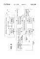
- antenna circuitry 50is comprised of an antenna coil 54, an antenna driver 56 and an antenna receiver 58.
- the rf readercommunicates with an rf tag via rf antenna 54.
- antenna driver 56is employed.
- antenna receiver 58is used.
- rf antenna 54is formed of wire-wrapped ferrite which is securely "potted” or mounted within rotatably adjustable head assembly 18 of FIG. 1.
- reader body circuit 60is comprised of a synchronous switching power supply 62, a transmit modulator 64, a receive demodulator 66, an interface controller 68, with a built-in menu 68a, a non-volatile memory 69, input buffers 70, and output buffers 72.
- Modulator 64is electrically coupled to antenna driver 56.
- Demodulator 66is coupled to antenna receiver 58.
- the interface controller 68activates modulator 64 to produce an interrogation signal.
- the interrogation signalis transferred through antenna driver 56 to antenna coil 54.
- the interrogationis then transmitted to the rf tag.
- response signalsare received, they are routed through antenna receiver 58, to demodulator 66, to interface controller 68 and out through output buffers 72.
- antenna circuitry 52 and read/write electronics circuitry 60are integrated into a single, compact structure, no extended electrical connections are required between antenna circuitry 52 and read/write electronics circuitry 60. As a result, the present invention does not suffer from significant power loss or electrical noise during the transfer of signals between antenna circuitry 52 and read/write electronics circuitry 60 as found in conventional two-piece rf reader units.
- antenna driver 56generates an interrogation signal which is transmitted from rf antenna 54 at a frequency of approximately 134 KHz. Response signals from the rf tag are received at a frequency of approximately 33.5 KHz. Thus, random voltage spikes or noise generated by a power supply of a conventional rf reader can obscure or mask response signals.
- a sync signalis supplied to switching power supply circuit 78 by modulator 64 of FIG. 5. The sync signal causes any switching transients to occur coincident with the interrogation frequency. Because the switching transients occur at a precise frequency as opposed to a randomly varying frequency, the transients can be filtered out by a filter with fixed components and a fixed notch frequency. Additionally, because the frequency is synchronous with the transmitting frequency of rf antenna 54 of FIG. 1, there are no inter-modulation products. Thus, the present invention eliminates or substantially reduces random intermodulation by-products and noise found in conventional rf reader units.
- wire bus 100eliminates the need to separately wire each of multiple rf readers 88, 90, and 92 to a central controller. Instead of having multiple individual connections, wire bus 100 provides a single connection from the central controller to numerous rf reader units, thereby saving wire, connectors, space, and installation labor. Thus, the present invention is well suited to use in manufacturing facilities where numerous rf readers may be disposed at various locations. Instead of having numerous wire connections, a single bus line can facilitate the numerous rf readers wherever located within the manufacturing facility. Likewise, instead of having a separate central controller for each rf reader or for selected groups of rf readers, the present invention allows numerous distantly-located rf readers to be controlled using a single central controller.
- the read/write electronics of the present inventionalso includes a built-in menu and non-volatile memory for storing the configuration parameters of the rf reader unit.
- a built-in menuprogrammed into, for example, interface controller 68 of FIG. 5, the present invention allows a user at a central controller station to select and implement desired operating configuration parameters of the rf reader unit.
- the rf reader of the present inventiondoes not require the numerous programming button and switches found on conventional rf readers.
- the size of the present inventioncan be reduced to an extent not possible with conventional rf readers.
- the configuration parameters of the rf reader unitremain stored in the read/write electronics even if power is lost.
- the present inventiondoes not require a cable or other type of extended electrical connection between the antenna portion and the read/write electronics portion.
- the present inventiondoes not suffer from power loss or electrical noise due to extended electrical connections between the antenna portion and the read/write electronics portion.
- the present inventiondoes not generate noise which interferes with response signals from the tagged item.
- the present inventiondoes not require numerous buttons and switches to program, set, and store operating parameters for the rf reader unit.
Landscapes
- Engineering & Computer Science (AREA)
- Physics & Mathematics (AREA)
- Health & Medical Sciences (AREA)
- Toxicology (AREA)
- General Health & Medical Sciences (AREA)
- Electromagnetism (AREA)
- Computer Networks & Wireless Communication (AREA)
- Artificial Intelligence (AREA)
- Computer Vision & Pattern Recognition (AREA)
- General Physics & Mathematics (AREA)
- Theoretical Computer Science (AREA)
- Arrangements For Transmission Of Measured Signals (AREA)
- Near-Field Transmission Systems (AREA)
- Radar Systems Or Details Thereof (AREA)
- Input Circuits Of Receivers And Coupling Of Receivers And Audio Equipment (AREA)
Abstract
Description
Claims (20)
Priority Applications (8)
| Application Number | Priority Date | Filing Date | Title |
|---|---|---|---|
| US08/415,853US5621199A (en) | 1995-04-03 | 1995-04-03 | RFID reader |
| EP96909857AEP0879424B1 (en) | 1995-04-03 | 1996-03-22 | Radio frequency identification reader |
| JP53034496AJP3728699B2 (en) | 1995-04-03 | 1996-03-22 | Radio frequency identification reader |
| MXPA/A/1997/007342AMXPA97007342A (en) | 1995-04-03 | 1996-03-22 | Radio frecuen identification reader |
| DE69614151TDE69614151T2 (en) | 1995-04-03 | 1996-03-22 | RADIO FREQUENCY IDENTIFICATION READER |
| CA002217158ACA2217158A1 (en) | 1995-04-03 | 1996-03-22 | Radio frequency identification reader |
| PCT/US1996/004032WO1996031787A1 (en) | 1995-04-03 | 1996-03-22 | Radio frequency identification reader |
| AU59555/96AAU5955596A (en) | 1995-04-03 | 1996-03-22 | Radio frequency identification reader |
Applications Claiming Priority (1)
| Application Number | Priority Date | Filing Date | Title |
|---|---|---|---|
| US08/415,853US5621199A (en) | 1995-04-03 | 1995-04-03 | RFID reader |
Publications (1)
| Publication Number | Publication Date |
|---|---|
| US5621199Atrue US5621199A (en) | 1997-04-15 |
Family
ID=23647480
Family Applications (1)
| Application Number | Title | Priority Date | Filing Date |
|---|---|---|---|
| US08/415,853Expired - LifetimeUS5621199A (en) | 1995-04-03 | 1995-04-03 | RFID reader |
Country Status (7)
| Country | Link |
|---|---|
| US (1) | US5621199A (en) |
| EP (1) | EP0879424B1 (en) |
| JP (1) | JP3728699B2 (en) |
| AU (1) | AU5955596A (en) |
| CA (1) | CA2217158A1 (en) |
| DE (1) | DE69614151T2 (en) |
| WO (1) | WO1996031787A1 (en) |
Cited By (91)
| Publication number | Priority date | Publication date | Assignee | Title |
|---|---|---|---|---|
| WO1999046940A1 (en)* | 1998-03-13 | 1999-09-16 | Motorola Inc. | Synchronization method for rfid system including tags having different memory sizes |
| WO2000014694A1 (en)* | 1998-09-08 | 2000-03-16 | Escort Memory Systems | Multi-directional rfid antenna |
| US6367697B1 (en)* | 1997-08-28 | 2002-04-09 | Supersensor (Proprietary) Limited | Reader arrangement for an electronic identification system having a plurality of reader heads for energizing transponders |
| US20020183882A1 (en)* | 2000-10-20 | 2002-12-05 | Michael Dearing | RF point of sale and delivery method and system using communication with remote computer and having features to read a large number of RF tags |
| US20030102367A1 (en)* | 2000-04-20 | 2003-06-05 | Francois Monette | Automated manufacturing control system |
| US20040160233A1 (en)* | 2003-02-13 | 2004-08-19 | Forster Ian J. | RFID device tester and method |
| US20040178264A1 (en)* | 2000-10-20 | 2004-09-16 | Promega Corporation | Radio frequency identification method and system of distributing products |
| US20040195319A1 (en)* | 2003-04-03 | 2004-10-07 | Forster Ian J. | RFID device detection system and method |
| US20040200061A1 (en)* | 2003-04-11 | 2004-10-14 | Coleman James P. | Conductive pattern and method of making |
| WO2005043447A1 (en)* | 2003-10-27 | 2005-05-12 | Zih Corp | Reader for rfid transponders and corresponding method |
| US20050156040A1 (en)* | 2004-01-16 | 2005-07-21 | Young David H. | Radio frequency identification device with movable antenna |
| EP1377945A4 (en)* | 2001-03-19 | 2005-10-26 | Escort Memory Systems | Rfid tracking method and system |
| US20050243030A1 (en)* | 2004-04-29 | 2005-11-03 | Sang-Hyuck Ahn | Electron emission display and driving method thereof |
| WO2005109330A1 (en)* | 2004-05-06 | 2005-11-17 | Fractus, S.A. | Radio-frequency system in package including antenna |
| US20050276028A1 (en)* | 2004-06-15 | 2005-12-15 | Chartered Semiconductor Manufacturing Ltd. | Radio frequency identification system |
| US20060000907A1 (en)* | 2004-07-01 | 2006-01-05 | Forster Ian J | RFID device preparation system and method |
| US20060043177A1 (en)* | 2004-08-25 | 2006-03-02 | Nycz Jeffrey H | Automated pass-through surgical instrument tray reader |
| US20060049248A1 (en)* | 2004-09-03 | 2006-03-09 | Siemens Aktiengesellschaft | Method and system for uniquely labeling products |
| US20060055542A1 (en)* | 2004-09-13 | 2006-03-16 | Forster Ian J | RFID device with content insensitivity and position insensitivity |
| US20060054710A1 (en)* | 2003-04-10 | 2006-03-16 | Forster Ian J | RFID devices having self-compensating antennas and conductive shields |
| US20060091225A1 (en)* | 2003-11-04 | 2006-05-04 | Forster Ian J | RFID tag using a surface insensitive antenna structure |
| US20060097873A1 (en)* | 2004-11-10 | 2006-05-11 | Rockwell Automation Technologies, Inc. | Systems and methods that integrate radio frequency identification (RFID) technology with agent-based control systems |
| US20060109105A1 (en)* | 2004-11-22 | 2006-05-25 | Sdgi Holdings, Inc | Surgical instrument tray shipping tote identification system and methods of using same |
| US20060108411A1 (en)* | 2004-11-10 | 2006-05-25 | Rockwell Automation Technologies, Inc. | Systems and methods that integrate radio frequency identification (RFID) technology with industrial controllers |
| US20060119481A1 (en)* | 2004-12-08 | 2006-06-08 | Sdgi Holdings, Inc | Workstation RFID reader for surgical instruments and surgical instrument trays and methods of using same |
| US20060132312A1 (en)* | 2004-12-02 | 2006-06-22 | Tavormina Joseph J | Portal antenna for radio frequency identification |
| US20060145856A1 (en)* | 2004-11-22 | 2006-07-06 | Sdgi Holdings, Inc. | Systems and methods for processing surgical instrument tray shipping totes |
| EP1693807A1 (en)* | 2001-03-19 | 2006-08-23 | Escort Memory Systems | RFID tracking method and system |
| US20060185781A1 (en)* | 2005-02-18 | 2006-08-24 | Mclaughlin Daniel | Apparatus and method for rejecting labels |
| US20060186999A1 (en)* | 2005-02-18 | 2006-08-24 | Ctm Integration, Inc. | Apparatus and method for reading/writing to RFID tags |
| US20060244593A1 (en)* | 2005-04-28 | 2006-11-02 | Sdgi Holdings, Inc. | Smart instrument tray RFID reader |
| US20060244652A1 (en)* | 2005-04-28 | 2006-11-02 | Sdgi Holdings, Inc. | Method and apparatus for surgical instrument identification |
| US7154283B1 (en) | 2006-02-22 | 2006-12-26 | Avery Dennison Corporation | Method of determining performance of RFID devices |
| US20070001839A1 (en)* | 2004-11-22 | 2007-01-04 | Cambre Christopher D | Control system for an rfid-based system for assembling and verifying outbound surgical equipment corresponding to a particular surgery |
| US20070018820A1 (en)* | 2005-07-20 | 2007-01-25 | Rockwell Automation Technologies, Inc. | Mobile RFID reader with integrated location awareness for material tracking and management |
| US20070018819A1 (en)* | 2005-07-19 | 2007-01-25 | Propack Data G.M.B.H | Reconciliation mechanism using RFID and sensors |
| US20070024463A1 (en)* | 2005-07-26 | 2007-02-01 | Rockwell Automation Technologies, Inc. | RFID tag data affecting automation controller with internal database |
| US20070035466A1 (en)* | 2003-04-11 | 2007-02-15 | Coleman James P | Conductive pattern and method of making |
| US20070039687A1 (en)* | 2005-08-22 | 2007-02-22 | Hamilton Kevin S | Method of making RFID devices |
| US20070052540A1 (en)* | 2005-09-06 | 2007-03-08 | Rockwell Automation Technologies, Inc. | Sensor fusion for RFID accuracy |
| US20070055470A1 (en)* | 2005-09-08 | 2007-03-08 | Rockwell Automation Technologies, Inc. | RFID architecture in an industrial controller environment |
| US20070063029A1 (en)* | 2005-09-20 | 2007-03-22 | Rockwell Automation Technologies, Inc. | RFID-based product manufacturing and lifecycle management |
| US20070075128A1 (en)* | 2005-09-30 | 2007-04-05 | Rockwell Automation Technologies, Inc. | Access to distributed databases via pointer stored in RFID tag |
| US20070075832A1 (en)* | 2005-09-30 | 2007-04-05 | Rockwell Automation Technologies, Inc. | RFID reader with programmable I/O control |
| US20070120742A1 (en)* | 2002-11-07 | 2007-05-31 | Fractus, S.A. | Radio-frequency system in package including antenna |
| US20080020645A1 (en)* | 2005-01-14 | 2008-01-24 | Fuerst Robert M | Filter connector |
| US20080047660A1 (en)* | 2006-08-08 | 2008-02-28 | Ws Packaging Group, Inc. | Peel plate assembly for removing programmable transponders from a web |
| US20080062049A1 (en)* | 2004-09-27 | 2008-03-13 | Fractus, S.A. | Tunable Antenna |
| US7376234B1 (en) | 2001-05-14 | 2008-05-20 | Hand Held Products, Inc. | Portable keying device and method |
| US20080198000A1 (en)* | 2007-02-18 | 2008-08-21 | James Neil Rodgers | RFID interrogation of liquid/metal |
| US20080265038A1 (en)* | 2004-07-23 | 2008-10-30 | Fractus, S.A. | Antenna in Package with Reduced Electromagnetic Interaction with on Chip Elements |
| US7446662B1 (en) | 2005-09-26 | 2008-11-04 | Rockwell Automation Technologies, Inc. | Intelligent RFID tag for magnetic field mapping |
| US7494058B2 (en) | 2004-07-01 | 2009-02-24 | American Express Travel Related Services Company, Inc. | Smartcard transaction method and system using voiceprint recognition |
| US7506819B2 (en) | 2001-07-10 | 2009-03-24 | Xatra Fund Mx, Llc | Biometric security using a fob |
| US7543738B1 (en) | 2001-07-10 | 2009-06-09 | American Express Travel Related Services Company, Inc. | System and method for secure transactions manageable by a transaction account provider |
| US7578448B2 (en) | 2001-07-10 | 2009-08-25 | Blayn W Beenau | Authorizing radio frequency transactions using a keystroke scan |
| US20090256679A1 (en)* | 2008-04-11 | 2009-10-15 | General Electric Company | Rfid based methods and systems for use in manufacturing and monitoring applications |
| US20090261659A1 (en)* | 2008-04-17 | 2009-10-22 | Carrick John C | Systems and methods for power supply synchronization in radio frequency identification (rfid) readers |
| US20090267743A1 (en)* | 2008-04-29 | 2009-10-29 | Kiely Per Faroe | Method and apparatus for a deployable radio-frequency identification portal system |
| US20090295541A1 (en)* | 2008-05-27 | 2009-12-03 | Intellidot Corporation | Directional rfid reader |
| US7636044B1 (en) | 2005-05-13 | 2009-12-22 | Rockwell Automation Technologies, Inc. | RFID tag programming, printing application, and supply chain/global registration architecture |
| US7639116B2 (en) | 2001-07-10 | 2009-12-29 | Peter D Saunders | Converting account data associated with a radio frequency device |
| US7668750B2 (en) | 2001-07-10 | 2010-02-23 | David S Bonalle | Securing RF transactions using a transactions counter |
| US7705732B2 (en) | 2001-07-10 | 2010-04-27 | Fred Bishop | Authenticating an RF transaction using a transaction counter |
| US7710275B2 (en) | 2007-03-16 | 2010-05-04 | Promega Corporation | RFID reader enclosure and man-o-war RFID reader system |
| US7725427B2 (en) | 2001-05-25 | 2010-05-25 | Fred Bishop | Recurrent billing maintenance with radio frequency payment devices |
| US7793845B2 (en) | 2004-07-01 | 2010-09-14 | American Express Travel Related Services Company, Inc. | Smartcard transaction system and method |
| US7886157B2 (en) | 2001-07-10 | 2011-02-08 | Xatra Fund Mx, Llc | Hand geometry recognition biometrics on a fob |
| US7889052B2 (en) | 2001-07-10 | 2011-02-15 | Xatra Fund Mx, Llc | Authorizing payment subsequent to RF transactions |
| US8001054B1 (en) | 2001-07-10 | 2011-08-16 | American Express Travel Related Services Company, Inc. | System and method for generating an unpredictable number using a seeded algorithm |
| USRE43157E1 (en) | 2002-09-12 | 2012-02-07 | Xatra Fund Mx, Llc | System and method for reassociating an account number to another transaction account |
| US8237570B1 (en) | 2007-06-13 | 2012-08-07 | Essen Energy Conversion Devices Pvt. Ltd. | Integrated, high efficiency RFID UHF reader/antenna |
| US8260948B2 (en) | 2005-08-10 | 2012-09-04 | Rockwell Automation Technologies, Inc. | Enhanced controller utilizing RFID technology |
| US8284025B2 (en) | 2001-07-10 | 2012-10-09 | Xatra Fund Mx, Llc | Method and system for auditory recognition biometrics on a FOB |
| US8717146B2 (en) | 2010-06-30 | 2014-05-06 | General Electric Company | Methods and systems for integrated interrogation of RFID sensors |
| US8872619B2 (en) | 2001-07-10 | 2014-10-28 | Xatra Fund Mx, Llc | Securing a transaction between a transponder and a reader |
| USRE45416E1 (en) | 2001-07-10 | 2015-03-17 | Xatra Fund Mx, Llc | Processing an RF transaction using a routing number |
| US9024719B1 (en) | 2001-07-10 | 2015-05-05 | Xatra Fund Mx, Llc | RF transaction system and method for storing user personal data |
| US9031880B2 (en) | 2001-07-10 | 2015-05-12 | Iii Holdings 1, Llc | Systems and methods for non-traditional payment using biometric data |
| US9454752B2 (en) | 2001-07-10 | 2016-09-27 | Chartoleaux Kg Limited Liability Company | Reload protocol at a transaction processing entity |
| US9747480B2 (en) | 2011-12-05 | 2017-08-29 | Adasa Inc. | RFID and robots for multichannel shopping |
| US9780435B2 (en) | 2011-12-05 | 2017-10-03 | Adasa Inc. | Aerial inventory antenna |
| US10050330B2 (en) | 2011-12-05 | 2018-08-14 | Adasa Inc. | Aerial inventory antenna |
| USRE47599E1 (en) | 2000-10-20 | 2019-09-10 | Promega Corporation | RF point of sale and delivery method and system using communication with remote computer and having features to read a large number of RF tags |
| US10476130B2 (en) | 2011-12-05 | 2019-11-12 | Adasa Inc. | Aerial inventory antenna |
| US10846497B2 (en) | 2011-12-05 | 2020-11-24 | Adasa Inc. | Holonomic RFID reader |
| US10872285B2 (en) | 2013-02-26 | 2020-12-22 | Quake Global, Inc. | Radio-frequency identification wristband with surface acoustic wave sensor |
| US10942246B2 (en) | 2013-02-25 | 2021-03-09 | Quake Global, Inc. | Ceiling-mounted RFID-enabled tracking |
| US11093722B2 (en) | 2011-12-05 | 2021-08-17 | Adasa Inc. | Holonomic RFID reader |
| US11211700B1 (en)* | 2019-03-11 | 2021-12-28 | Amazon Technologies, Inc. | Dynamic noise cancellation using noise patterns |
| US20220044802A1 (en)* | 2020-08-09 | 2022-02-10 | Kevin Patel | System for remote medical care |
Families Citing this family (2)
| Publication number | Priority date | Publication date | Assignee | Title |
|---|---|---|---|---|
| CN102804502B (en) | 2009-12-16 | 2015-12-02 | 阿丹特有限责任公司 | Meta Materials reconfigurable antennas |
| US20180062434A1 (en) | 2016-08-26 | 2018-03-01 | Nucurrent, Inc. | Wireless Connector Receiver Module Circuit |
Citations (14)
| Publication number | Priority date | Publication date | Assignee | Title |
|---|---|---|---|---|
| US4303904A (en)* | 1979-10-12 | 1981-12-01 | Chasek Norman E | Universally applicable, in-motion and automatic toll paying system using microwaves |
| US4364043A (en)* | 1979-05-30 | 1982-12-14 | The University Of Adelaide | Efficient object identification system |
| US4475481A (en)* | 1981-07-06 | 1984-10-09 | B.I. Incorporated | Identification system |
| US4656463A (en)* | 1983-04-21 | 1987-04-07 | Intelli-Tech Corporation | LIMIS systems, devices and methods |
| US4827115A (en)* | 1987-03-16 | 1989-05-02 | Omron Tateisi Electronics Co. | ID system and method or writing data in an ID system |
| US4918296A (en)* | 1987-03-06 | 1990-04-17 | Omron Tateisi Electronics Company | Article identifying system |
| US5053774A (en)* | 1987-07-31 | 1991-10-01 | Texas Instruments Deutschland Gmbh | Transponder arrangement |
| WO1993013494A1 (en)* | 1991-12-20 | 1993-07-08 | Gemplus Card International | Container identification system, particularly for gas cylinders |
| US5280159A (en)* | 1989-03-09 | 1994-01-18 | Norand Corporation | Magnetic radio frequency tag reader for use with a hand-held terminal |
| US5281855A (en)* | 1991-06-05 | 1994-01-25 | Trovan Limited | Integrated circuit device including means for facilitating connection of antenna lead wires to an integrated circuit die |
| US5306900A (en)* | 1988-05-11 | 1994-04-26 | Symbol Technologies, Inc. | Hand held bar code scanner with adjustment of direction of emitted light beam |
| US5335541A (en)* | 1992-02-20 | 1994-08-09 | Westland Aerospace Limited | Portable apparatus for measurement and display of internal pressure of tires |
| US5382784A (en)* | 1993-02-08 | 1995-01-17 | Indala Corporation | Hand-held dual technology identification tag reading head |
| US5486661A (en)* | 1994-07-12 | 1996-01-23 | Eaton Corporation | Limit switch lever |
Family Cites Families (3)
| Publication number | Priority date | Publication date | Assignee | Title |
|---|---|---|---|---|
| US4178592A (en)* | 1978-01-23 | 1979-12-11 | Mckee Maureen K | Fire alarm having a sensor on an extensible arm |
| US4831438A (en)* | 1987-02-25 | 1989-05-16 | Household Data Services | Electronic surveillance system |
| US5387916A (en)* | 1992-07-31 | 1995-02-07 | Westinghouse Electric Corporation | Automotive navigation system and method |
- 1995
- 1995-04-03USUS08/415,853patent/US5621199A/ennot_activeExpired - Lifetime
- 1996
- 1996-03-22WOPCT/US1996/004032patent/WO1996031787A1/enactiveIP Right Grant
- 1996-03-22DEDE69614151Tpatent/DE69614151T2/ennot_activeExpired - Fee Related
- 1996-03-22JPJP53034496Apatent/JP3728699B2/ennot_activeExpired - Fee Related
- 1996-03-22AUAU59555/96Apatent/AU5955596A/ennot_activeAbandoned
- 1996-03-22EPEP96909857Apatent/EP0879424B1/ennot_activeExpired - Lifetime
- 1996-03-22CACA002217158Apatent/CA2217158A1/ennot_activeAbandoned
Patent Citations (14)
| Publication number | Priority date | Publication date | Assignee | Title |
|---|---|---|---|---|
| US4364043A (en)* | 1979-05-30 | 1982-12-14 | The University Of Adelaide | Efficient object identification system |
| US4303904A (en)* | 1979-10-12 | 1981-12-01 | Chasek Norman E | Universally applicable, in-motion and automatic toll paying system using microwaves |
| US4475481A (en)* | 1981-07-06 | 1984-10-09 | B.I. Incorporated | Identification system |
| US4656463A (en)* | 1983-04-21 | 1987-04-07 | Intelli-Tech Corporation | LIMIS systems, devices and methods |
| US4918296A (en)* | 1987-03-06 | 1990-04-17 | Omron Tateisi Electronics Company | Article identifying system |
| US4827115A (en)* | 1987-03-16 | 1989-05-02 | Omron Tateisi Electronics Co. | ID system and method or writing data in an ID system |
| US5053774A (en)* | 1987-07-31 | 1991-10-01 | Texas Instruments Deutschland Gmbh | Transponder arrangement |
| US5306900A (en)* | 1988-05-11 | 1994-04-26 | Symbol Technologies, Inc. | Hand held bar code scanner with adjustment of direction of emitted light beam |
| US5280159A (en)* | 1989-03-09 | 1994-01-18 | Norand Corporation | Magnetic radio frequency tag reader for use with a hand-held terminal |
| US5281855A (en)* | 1991-06-05 | 1994-01-25 | Trovan Limited | Integrated circuit device including means for facilitating connection of antenna lead wires to an integrated circuit die |
| WO1993013494A1 (en)* | 1991-12-20 | 1993-07-08 | Gemplus Card International | Container identification system, particularly for gas cylinders |
| US5335541A (en)* | 1992-02-20 | 1994-08-09 | Westland Aerospace Limited | Portable apparatus for measurement and display of internal pressure of tires |
| US5382784A (en)* | 1993-02-08 | 1995-01-17 | Indala Corporation | Hand-held dual technology identification tag reading head |
| US5486661A (en)* | 1994-07-12 | 1996-01-23 | Eaton Corporation | Limit switch lever |
Cited By (205)
| Publication number | Priority date | Publication date | Assignee | Title |
|---|---|---|---|---|
| US6367697B1 (en)* | 1997-08-28 | 2002-04-09 | Supersensor (Proprietary) Limited | Reader arrangement for an electronic identification system having a plurality of reader heads for energizing transponders |
| WO1999046940A1 (en)* | 1998-03-13 | 1999-09-16 | Motorola Inc. | Synchronization method for rfid system including tags having different memory sizes |
| WO2000014694A1 (en)* | 1998-09-08 | 2000-03-16 | Escort Memory Systems | Multi-directional rfid antenna |
| US6069564A (en)* | 1998-09-08 | 2000-05-30 | Hatano; Richard | Multi-directional RFID antenna |
| US7069100B2 (en) | 2000-04-20 | 2006-06-27 | Cogiscan Inc. | Automated manufacturing control system |
| US20030102367A1 (en)* | 2000-04-20 | 2003-06-05 | Francois Monette | Automated manufacturing control system |
| US7286888B2 (en) | 2000-04-20 | 2007-10-23 | Cogiscan Inc. | Automated manufacturing control system |
| US20050194437A1 (en)* | 2000-10-20 | 2005-09-08 | Promega Corporation | RF point of sale and delivery method and system using communication with remote computer and having features to read a large number of RF tags |
| US7942321B2 (en) | 2000-10-20 | 2011-05-17 | Promega Corporation | Radio frequency identification method and system of disturbing products |
| USRE46326E1 (en) | 2000-10-20 | 2017-02-28 | Promega Corporation | RF point of sale and delivery method and system using communication with remote computer and having features to read a large number of RF tags |
| US20040222297A1 (en)* | 2000-10-20 | 2004-11-11 | Promega Corporation | RF point of sale and delivery method and system using communication with remote computer and having features to read a large number of RF tags |
| US20040222298A1 (en)* | 2000-10-20 | 2004-11-11 | Promega Corporation | RF point of sale and delivery method and system using communication with remote computer and having features to read a large number of RF tags |
| US20040232230A1 (en)* | 2000-10-20 | 2004-11-25 | Promega Corporation | Radio frequency identification method and system of distributing products |
| US20040232231A1 (en)* | 2000-10-20 | 2004-11-25 | Promega Corporation | Radio frequency identification method and system of distributing products |
| US7735732B2 (en) | 2000-10-20 | 2010-06-15 | Promega Corporation | Radio frequency identification method and system of distributing products |
| US7784689B2 (en) | 2000-10-20 | 2010-08-31 | Promega Corporation | Radio frequency identification method and system of distributing products |
| US20040178264A1 (en)* | 2000-10-20 | 2004-09-16 | Promega Corporation | Radio frequency identification method and system of distributing products |
| US7791479B2 (en) | 2000-10-20 | 2010-09-07 | Promega Corporation | RFID point of sale and delivery method and system |
| US8231053B2 (en) | 2000-10-20 | 2012-07-31 | Promega Corporation | Radio frequency identification method and system of distributing products |
| US20060081705A1 (en)* | 2000-10-20 | 2006-04-20 | Promega Corporation | Radio frequency identification method and system of distributing products |
| US7591421B2 (en) | 2000-10-20 | 2009-09-22 | Promega Corporation | Radio frequency identification method and system of distributing products |
| US7967199B2 (en) | 2000-10-20 | 2011-06-28 | Promega Corporation | Radio frequency identification method and system of distributing products |
| US7293705B2 (en) | 2000-10-20 | 2007-11-13 | Promega Corporation | Radio frequency identification method and system of distributing products |
| US7661591B2 (en) | 2000-10-20 | 2010-02-16 | Promega Corporation | RF point of sale and delivery method and system using communication with remote computer and having features to read a large number of RF tags |
| USRE47599E1 (en) | 2000-10-20 | 2019-09-10 | Promega Corporation | RF point of sale and delivery method and system using communication with remote computer and having features to read a large number of RF tags |
| US8025228B2 (en) | 2000-10-20 | 2011-09-27 | Promega Corporation | RF point of sale and delivery method and system using communication with remote computer and having features to read a large number of RF tags |
| US7258276B2 (en) | 2000-10-20 | 2007-08-21 | Promega Corporation | Radio frequency identification method and system of distributing products |
| US20020183882A1 (en)* | 2000-10-20 | 2002-12-05 | Michael Dearing | RF point of sale and delivery method and system using communication with remote computer and having features to read a large number of RF tags |
| US8113425B2 (en) | 2000-10-20 | 2012-02-14 | Promega Corporation | RF point of sale and delivery method and system using communication with remote computer and having features to read a large number of RF tags |
| EP1377945A4 (en)* | 2001-03-19 | 2005-10-26 | Escort Memory Systems | Rfid tracking method and system |
| EP1693807A1 (en)* | 2001-03-19 | 2006-08-23 | Escort Memory Systems | RFID tracking method and system |
| US7376234B1 (en) | 2001-05-14 | 2008-05-20 | Hand Held Products, Inc. | Portable keying device and method |
| US9137009B1 (en) | 2001-05-14 | 2015-09-15 | Hand Held Products, Inc. | Portable keying device and method |
| US7725427B2 (en) | 2001-05-25 | 2010-05-25 | Fred Bishop | Recurrent billing maintenance with radio frequency payment devices |
| US7886157B2 (en) | 2001-07-10 | 2011-02-08 | Xatra Fund Mx, Llc | Hand geometry recognition biometrics on a fob |
| US9024719B1 (en) | 2001-07-10 | 2015-05-05 | Xatra Fund Mx, Llc | RF transaction system and method for storing user personal data |
| US7637434B2 (en) | 2001-07-10 | 2009-12-29 | Blayn W Beenau | Registering a biometric for radio frequency transactions |
| US9454752B2 (en) | 2001-07-10 | 2016-09-27 | Chartoleaux Kg Limited Liability Company | Reload protocol at a transaction processing entity |
| US7578448B2 (en) | 2001-07-10 | 2009-08-25 | Blayn W Beenau | Authorizing radio frequency transactions using a keystroke scan |
| US8284025B2 (en) | 2001-07-10 | 2012-10-09 | Xatra Fund Mx, Llc | Method and system for auditory recognition biometrics on a FOB |
| US9886692B2 (en) | 2001-07-10 | 2018-02-06 | Chartoleaux Kg Limited Liability Company | Securing a transaction between a transponder and a reader |
| US7889052B2 (en) | 2001-07-10 | 2011-02-15 | Xatra Fund Mx, Llc | Authorizing payment subsequent to RF transactions |
| US9031880B2 (en) | 2001-07-10 | 2015-05-12 | Iii Holdings 1, Llc | Systems and methods for non-traditional payment using biometric data |
| US7639116B2 (en) | 2001-07-10 | 2009-12-29 | Peter D Saunders | Converting account data associated with a radio frequency device |
| US7506819B2 (en) | 2001-07-10 | 2009-03-24 | Xatra Fund Mx, Llc | Biometric security using a fob |
| US7543738B1 (en) | 2001-07-10 | 2009-06-09 | American Express Travel Related Services Company, Inc. | System and method for secure transactions manageable by a transaction account provider |
| USRE45416E1 (en) | 2001-07-10 | 2015-03-17 | Xatra Fund Mx, Llc | Processing an RF transaction using a routing number |
| US8001054B1 (en) | 2001-07-10 | 2011-08-16 | American Express Travel Related Services Company, Inc. | System and method for generating an unpredictable number using a seeded algorithm |
| US8872619B2 (en) | 2001-07-10 | 2014-10-28 | Xatra Fund Mx, Llc | Securing a transaction between a transponder and a reader |
| US7668750B2 (en) | 2001-07-10 | 2010-02-23 | David S Bonalle | Securing RF transactions using a transactions counter |
| US7690577B2 (en) | 2001-07-10 | 2010-04-06 | Blayn W Beenau | Registering a biometric for radio frequency transactions |
| US8548927B2 (en) | 2001-07-10 | 2013-10-01 | Xatra Fund Mx, Llc | Biometric registration for facilitating an RF transaction |
| US7705732B2 (en) | 2001-07-10 | 2010-04-27 | Fred Bishop | Authenticating an RF transaction using a transaction counter |
| US20080135613A1 (en)* | 2002-02-21 | 2008-06-12 | Promega Corporation | RF point of sale and delivery method and system using communication with remote computer and having features to read a large number of RF tags |
| RU2321059C2 (en)* | 2002-02-21 | 2008-03-27 | Промега Корпорейшн | Radio-frequency vending station and delivery system which uses connection to remote computer, both capable of reading large number of radio frequency labels |
| EP1485775A4 (en)* | 2002-02-21 | 2006-08-16 | Promega Corp | Rf point of sale and delivery method and system using communication with remote computer and having features to read a large number of rf tags |
| US20080116269A1 (en)* | 2002-02-21 | 2008-05-22 | Promega Corporation | RF point of sale and delivery method and system using communication with remote computer and having features to read a large number of RF tags |
| USRE43157E1 (en) | 2002-09-12 | 2012-02-07 | Xatra Fund Mx, Llc | System and method for reassociating an account number to another transaction account |
| US7791539B2 (en) | 2002-11-07 | 2010-09-07 | Fractus, S.A. | Radio-frequency system in package including antenna |
| US20100328185A1 (en)* | 2002-11-07 | 2010-12-30 | Jordi Soler Castany | Radio-frequency system in package including antenna |
| US9761948B2 (en) | 2002-11-07 | 2017-09-12 | Fractus, S.A. | Integrated circuit package including miniature antenna |
| US20070120742A1 (en)* | 2002-11-07 | 2007-05-31 | Fractus, S.A. | Radio-frequency system in package including antenna |
| US9077073B2 (en) | 2002-11-07 | 2015-07-07 | Fractus, S.A. | Integrated circuit package including miniature antenna |
| US10056691B2 (en) | 2002-11-07 | 2018-08-21 | Fractus, S.A. | Integrated circuit package including miniature antenna |
| US20090085810A1 (en)* | 2002-11-07 | 2009-04-02 | Fractus, S.A. | Integrated circuit package including miniature antenna |
| US8203488B2 (en) | 2002-11-07 | 2012-06-19 | Fractus, S.A. | Integrated circuit package including miniature antenna |
| US10320079B2 (en) | 2002-11-07 | 2019-06-11 | Fractus, S.A. | Integrated circuit package including miniature antenna |
| US7463199B2 (en) | 2002-11-07 | 2008-12-09 | Fractus, S.A. | Integrated circuit package including miniature antenna |
| US10644405B2 (en) | 2002-11-07 | 2020-05-05 | Fractus, S.A. | Integrated circuit package including miniature antenna |
| US8421686B2 (en) | 2002-11-07 | 2013-04-16 | Fractus, S.A. | Radio-frequency system in package including antenna |
| US20040160233A1 (en)* | 2003-02-13 | 2004-08-19 | Forster Ian J. | RFID device tester and method |
| US7225992B2 (en) | 2003-02-13 | 2007-06-05 | Avery Dennison Corporation | RFID device tester and method |
| US7306162B2 (en) | 2003-02-13 | 2007-12-11 | Avery Dennison Corporation | RFID device tester and method |
| US20050223286A1 (en)* | 2003-02-13 | 2005-10-06 | Forster Ian J | RFID device tester and method |
| EP2264678A1 (en) | 2003-02-13 | 2010-12-22 | Avery Dennison Corporation | RFID device tester and method |
| US7059518B2 (en) | 2003-04-03 | 2006-06-13 | Avery Dennison Corporation | RFID device detection system and method |
| US7273173B2 (en) | 2003-04-03 | 2007-09-25 | Avery Dennison Corporation | RFID device detection system and method |
| US20060192002A1 (en)* | 2003-04-03 | 2006-08-31 | Forster Ian J | RFID device detection system and method |
| US20040195319A1 (en)* | 2003-04-03 | 2004-10-07 | Forster Ian J. | RFID device detection system and method |
| US20060054710A1 (en)* | 2003-04-10 | 2006-03-16 | Forster Ian J | RFID devices having self-compensating antennas and conductive shields |
| US7652636B2 (en) | 2003-04-10 | 2010-01-26 | Avery Dennison Corporation | RFID devices having self-compensating antennas and conductive shields |
| US20070080233A1 (en)* | 2003-04-10 | 2007-04-12 | Forster Ian J | RFID tag using a surface insensitive antenna structure |
| US7379024B2 (en) | 2003-04-10 | 2008-05-27 | Avery Dennison Corporation | RFID tag using a surface insensitive antenna structure |
| US7477194B2 (en) | 2003-04-11 | 2009-01-13 | Avery Dennison Corporation | Conductive pattern and method of making |
| US7930815B2 (en) | 2003-04-11 | 2011-04-26 | Avery Dennison Corporation | Conductive pattern and method of making |
| US9159018B2 (en) | 2003-04-11 | 2015-10-13 | Avery Dennison Corporation | Method of making conductive patterns |
| US20060283005A1 (en)* | 2003-04-11 | 2006-12-21 | Coleman James P | Conductive pattern and method of making |
| US8769805B2 (en) | 2003-04-11 | 2014-07-08 | Avery Dennison Corporation | Method of making conductive pattern |
| US20100283615A1 (en)* | 2003-04-11 | 2010-11-11 | Avery Dennison Corporation | Conductive Pattern and Method of Making |
| US20070035466A1 (en)* | 2003-04-11 | 2007-02-15 | Coleman James P | Conductive pattern and method of making |
| US20040200061A1 (en)* | 2003-04-11 | 2004-10-14 | Coleman James P. | Conductive pattern and method of making |
| US20060076422A1 (en)* | 2003-04-11 | 2006-04-13 | Coleman James P | Conductive pattern and method of making |
| US20070252698A1 (en)* | 2003-10-27 | 2007-11-01 | Turner Christopher G G | Reader for Rfid Transponders and Corresponding Method |
| US7683788B2 (en) | 2003-10-27 | 2010-03-23 | Zih Corp. | Reader for RFID transponders and corresponding method |
| WO2005043447A1 (en)* | 2003-10-27 | 2005-05-12 | Zih Corp | Reader for rfid transponders and corresponding method |
| US20060091225A1 (en)* | 2003-11-04 | 2006-05-04 | Forster Ian J | RFID tag using a surface insensitive antenna structure |
| US7501984B2 (en) | 2003-11-04 | 2009-03-10 | Avery Dennison Corporation | RFID tag using a surface insensitive antenna structure |
| US20070262869A1 (en)* | 2004-01-16 | 2007-11-15 | Two Technologies, Inc. | Radio frequency identification device with movable antenna |
| US20050156040A1 (en)* | 2004-01-16 | 2005-07-21 | Young David H. | Radio frequency identification device with movable antenna |
| US7250845B2 (en)* | 2004-01-16 | 2007-07-31 | Two Technologies, Inc. | Radio frequency identification device with movable antenna |
| WO2005072137A3 (en)* | 2004-01-16 | 2006-11-02 | Two Technologies Inc | Radio frequency identification device with movable antenna |
| US20050243030A1 (en)* | 2004-04-29 | 2005-11-03 | Sang-Hyuck Ahn | Electron emission display and driving method thereof |
| WO2005109330A1 (en)* | 2004-05-06 | 2005-11-17 | Fractus, S.A. | Radio-frequency system in package including antenna |
| US8672231B2 (en) | 2004-06-15 | 2014-03-18 | Globalfoundries Singapore Pte. Ltd. | Integrated circuit system with antenna |
| US20090014543A1 (en)* | 2004-06-15 | 2009-01-15 | Chartered Semiconductor Manufacturing Ltd. | Integrated circuit system with antenna |
| US20050276028A1 (en)* | 2004-06-15 | 2005-12-15 | Chartered Semiconductor Manufacturing Ltd. | Radio frequency identification system |
| US7444735B2 (en) | 2004-06-15 | 2008-11-04 | Chartered Semiconductor Manufacturing Ltd. | Process for manufacturing an integrated circuit system |
| US7307527B2 (en) | 2004-07-01 | 2007-12-11 | Avery Dennison Corporation | RFID device preparation system and method |
| US8016191B2 (en) | 2004-07-01 | 2011-09-13 | American Express Travel Related Services Company, Inc. | Smartcard transaction system and method |
| US7494058B2 (en) | 2004-07-01 | 2009-02-24 | American Express Travel Related Services Company, Inc. | Smartcard transaction method and system using voiceprint recognition |
| US7793845B2 (en) | 2004-07-01 | 2010-09-14 | American Express Travel Related Services Company, Inc. | Smartcard transaction system and method |
| US20060000907A1 (en)* | 2004-07-01 | 2006-01-05 | Forster Ian J | RFID device preparation system and method |
| US8330259B2 (en) | 2004-07-23 | 2012-12-11 | Fractus, S.A. | Antenna in package with reduced electromagnetic interaction with on chip elements |
| US20080265038A1 (en)* | 2004-07-23 | 2008-10-30 | Fractus, S.A. | Antenna in Package with Reduced Electromagnetic Interaction with on Chip Elements |
| US8082192B2 (en) | 2004-08-25 | 2011-12-20 | Warsaw Orthopedic, Inc. | Automated pass-through surgical instrument tray reader |
| US20100108761A1 (en)* | 2004-08-25 | 2010-05-06 | Warsaw Orthopedic, Inc. | Automated Pass-Through Surgical Instrument Tray Reader |
| US7644016B2 (en) | 2004-08-25 | 2010-01-05 | Warsaw Orthopedic, Inc. | Automated pass-through surgical instrument tray reader |
| US20060043177A1 (en)* | 2004-08-25 | 2006-03-02 | Nycz Jeffrey H | Automated pass-through surgical instrument tray reader |
| US20060049248A1 (en)* | 2004-09-03 | 2006-03-09 | Siemens Aktiengesellschaft | Method and system for uniquely labeling products |
| EP1645997A2 (en) | 2004-09-03 | 2006-04-12 | Siemens Aktiengesellschaft | Method and system for uniquely labelling products |
| US20060055542A1 (en)* | 2004-09-13 | 2006-03-16 | Forster Ian J | RFID device with content insensitivity and position insensitivity |
| US7501955B2 (en) | 2004-09-13 | 2009-03-10 | Avery Dennison Corporation | RFID device with content insensitivity and position insensitivity |
| US7924226B2 (en) | 2004-09-27 | 2011-04-12 | Fractus, S.A. | Tunable antenna |
| US20080062049A1 (en)* | 2004-09-27 | 2008-03-13 | Fractus, S.A. | Tunable Antenna |
| US7997475B2 (en) | 2004-11-10 | 2011-08-16 | Rockwell Automation Technologies, Inc. | Systems and methods that integrate radio frequency identification (RFID) technology with industrial controllers |
| US7994919B2 (en) | 2004-11-10 | 2011-08-09 | Rockwell Automation Technologies, Inc. | Systems and methods that integrate radio frequency identification (RFID) technology with agent-based control systems |
| US7551081B2 (en) | 2004-11-10 | 2009-06-23 | Rockwell Automation Technologies, Inc. | Systems and methods that integrate radio frequency identification (RFID) technology with agent-based control systems |
| US8384544B2 (en) | 2004-11-10 | 2013-02-26 | Rockwell Automation Technologies, Inc. | Systems and methods that integrate radio frequency identification (RFID) technology with agent-based control systems |
| US20090243808A1 (en)* | 2004-11-10 | 2009-10-01 | Rockwell Automation Technologies, Inc. | Systems and methods that integrate radio frequency identification (rfid) technology with agent-based control systems |
| US20060108411A1 (en)* | 2004-11-10 | 2006-05-25 | Rockwell Automation Technologies, Inc. | Systems and methods that integrate radio frequency identification (RFID) technology with industrial controllers |
| US7339476B2 (en) | 2004-11-10 | 2008-03-04 | Rockwell Automation Technologies, Inc. | Systems and methods that integrate radio frequency identification (RFID) technology with industrial controllers |
| US20060097873A1 (en)* | 2004-11-10 | 2006-05-11 | Rockwell Automation Technologies, Inc. | Systems and methods that integrate radio frequency identification (RFID) technology with agent-based control systems |
| US7492261B2 (en) | 2004-11-22 | 2009-02-17 | Warsaw Orthopedic, Inc. | Control system for an RFID-based system for assembling and verifying outbound surgical equipment corresponding to a particular surgery |
| US7492257B2 (en) | 2004-11-22 | 2009-02-17 | Warsaw Orthopedic, Inc. | Systems and methods for processing surgical instrument tray shipping totes |
| US20060109105A1 (en)* | 2004-11-22 | 2006-05-25 | Sdgi Holdings, Inc | Surgical instrument tray shipping tote identification system and methods of using same |
| US20060145856A1 (en)* | 2004-11-22 | 2006-07-06 | Sdgi Holdings, Inc. | Systems and methods for processing surgical instrument tray shipping totes |
| US7227469B2 (en) | 2004-11-22 | 2007-06-05 | Sdgi Holdings, Inc. | Surgical instrument tray shipping tote identification system and methods of using same |
| US20070001839A1 (en)* | 2004-11-22 | 2007-01-04 | Cambre Christopher D | Control system for an rfid-based system for assembling and verifying outbound surgical equipment corresponding to a particular surgery |
| US20060132312A1 (en)* | 2004-12-02 | 2006-06-22 | Tavormina Joseph J | Portal antenna for radio frequency identification |
| US7268684B2 (en) | 2004-12-08 | 2007-09-11 | Sdgi Holdings, Inc. | Workstation RFID reader for surgical instruments and surgical instrument trays and methods of using same |
| US20060119481A1 (en)* | 2004-12-08 | 2006-06-08 | Sdgi Holdings, Inc | Workstation RFID reader for surgical instruments and surgical instrument trays and methods of using same |
| US7442085B2 (en) | 2005-01-14 | 2008-10-28 | Molex Incorporated | Filter connector |
| US20080020645A1 (en)* | 2005-01-14 | 2008-01-24 | Fuerst Robert M | Filter connector |
| US20060186999A1 (en)* | 2005-02-18 | 2006-08-24 | Ctm Integration, Inc. | Apparatus and method for reading/writing to RFID tags |
| US20060185781A1 (en)* | 2005-02-18 | 2006-08-24 | Mclaughlin Daniel | Apparatus and method for rejecting labels |
| US7362228B2 (en) | 2005-04-28 | 2008-04-22 | Warsaw Orthepedic, Inc. | Smart instrument tray RFID reader |
| US7837694B2 (en) | 2005-04-28 | 2010-11-23 | Warsaw Orthopedic, Inc. | Method and apparatus for surgical instrument identification |
| US20100176925A1 (en)* | 2005-04-28 | 2010-07-15 | Warsaw Orthopedic, Inc. | Method and Apparatus for Surgical Instrument Identification |
| US8454613B2 (en) | 2005-04-28 | 2013-06-04 | Warsaw Orthopedic, Inc. | Method and apparatus for surgical instrument identification |
| US20060244593A1 (en)* | 2005-04-28 | 2006-11-02 | Sdgi Holdings, Inc. | Smart instrument tray RFID reader |
| US20060244652A1 (en)* | 2005-04-28 | 2006-11-02 | Sdgi Holdings, Inc. | Method and apparatus for surgical instrument identification |
| US7636044B1 (en) | 2005-05-13 | 2009-12-22 | Rockwell Automation Technologies, Inc. | RFID tag programming, printing application, and supply chain/global registration architecture |
| US20070018819A1 (en)* | 2005-07-19 | 2007-01-25 | Propack Data G.M.B.H | Reconciliation mechanism using RFID and sensors |
| US7616117B2 (en) | 2005-07-19 | 2009-11-10 | Rockwell Automation Technologies, Inc. | Reconciliation mechanism using RFID and sensors |
| US7932827B2 (en) | 2005-07-20 | 2011-04-26 | Rockwell Automation Technologies, Inc. | Mobile RFID reader with integrated location awareness for material tracking and management |
| US20070018820A1 (en)* | 2005-07-20 | 2007-01-25 | Rockwell Automation Technologies, Inc. | Mobile RFID reader with integrated location awareness for material tracking and management |
| US20080278328A1 (en)* | 2005-07-20 | 2008-11-13 | Rockwell Automation Technologies, Inc. | Mobile rfid reader with integrated location awareness for material tracking and management |
| US7388491B2 (en) | 2005-07-20 | 2008-06-17 | Rockwell Automation Technologies, Inc. | Mobile RFID reader with integrated location awareness for material tracking and management |
| US7764191B2 (en) | 2005-07-26 | 2010-07-27 | Rockwell Automation Technologies, Inc. | RFID tag data affecting automation controller with internal database |
| US20070024463A1 (en)* | 2005-07-26 | 2007-02-01 | Rockwell Automation Technologies, Inc. | RFID tag data affecting automation controller with internal database |
| US8260948B2 (en) | 2005-08-10 | 2012-09-04 | Rockwell Automation Technologies, Inc. | Enhanced controller utilizing RFID technology |
| US7842152B2 (en) | 2005-08-22 | 2010-11-30 | Avery Dennison Corporation | Method of making RFID devices |
| US20070039687A1 (en)* | 2005-08-22 | 2007-02-22 | Hamilton Kevin S | Method of making RFID devices |
| US20070052540A1 (en)* | 2005-09-06 | 2007-03-08 | Rockwell Automation Technologies, Inc. | Sensor fusion for RFID accuracy |
| US20090206154A1 (en)* | 2005-09-08 | 2009-08-20 | Rockwell Automation Technologies, Inc. | Rfid architecture in an industrial controller environment |
| US20070055470A1 (en)* | 2005-09-08 | 2007-03-08 | Rockwell Automation Technologies, Inc. | RFID architecture in an industrial controller environment |
| US8152053B2 (en) | 2005-09-08 | 2012-04-10 | Rockwell Automation Technologies, Inc. | RFID architecture in an industrial controller environment |
| US7510110B2 (en) | 2005-09-08 | 2009-03-31 | Rockwell Automation Technologies, Inc. | RFID architecture in an industrial controller environment |
| US7931197B2 (en) | 2005-09-20 | 2011-04-26 | Rockwell Automation Technologies, Inc. | RFID-based product manufacturing and lifecycle management |
| US20070063029A1 (en)* | 2005-09-20 | 2007-03-22 | Rockwell Automation Technologies, Inc. | RFID-based product manufacturing and lifecycle management |
| US7772978B1 (en) | 2005-09-26 | 2010-08-10 | Rockwell Automation Technologies, Inc. | Intelligent RFID tag for magnetic field mapping |
| US7446662B1 (en) | 2005-09-26 | 2008-11-04 | Rockwell Automation Technologies, Inc. | Intelligent RFID tag for magnetic field mapping |
| US20070075832A1 (en)* | 2005-09-30 | 2007-04-05 | Rockwell Automation Technologies, Inc. | RFID reader with programmable I/O control |
| US8025227B2 (en)* | 2005-09-30 | 2011-09-27 | Rockwell Automation Technologies, Inc. | Access to distributed databases via pointer stored in RFID tag |
| US20070075128A1 (en)* | 2005-09-30 | 2007-04-05 | Rockwell Automation Technologies, Inc. | Access to distributed databases via pointer stored in RFID tag |
| US7154283B1 (en) | 2006-02-22 | 2006-12-26 | Avery Dennison Corporation | Method of determining performance of RFID devices |
| US20080047660A1 (en)* | 2006-08-08 | 2008-02-28 | Ws Packaging Group, Inc. | Peel plate assembly for removing programmable transponders from a web |
| US20080198000A1 (en)* | 2007-02-18 | 2008-08-21 | James Neil Rodgers | RFID interrogation of liquid/metal |
| US8031072B2 (en) | 2007-03-16 | 2011-10-04 | Promega Corporation | RFID reader enclosure and man-o-war RFID reader system |
| US8258961B2 (en) | 2007-03-16 | 2012-09-04 | Promega Corporation | RFID reader enclosure and man-o-war RFID reader system |
| US7710275B2 (en) | 2007-03-16 | 2010-05-04 | Promega Corporation | RFID reader enclosure and man-o-war RFID reader system |
| US8237570B1 (en) | 2007-06-13 | 2012-08-07 | Essen Energy Conversion Devices Pvt. Ltd. | Integrated, high efficiency RFID UHF reader/antenna |
| US20090256679A1 (en)* | 2008-04-11 | 2009-10-15 | General Electric Company | Rfid based methods and systems for use in manufacturing and monitoring applications |
| US8196831B2 (en)* | 2008-04-17 | 2012-06-12 | Trimble Navigation Limited | Systems and methods for power supply synchronization in radio frequency identification (RFID) readers |
| US20090261659A1 (en)* | 2008-04-17 | 2009-10-22 | Carrick John C | Systems and methods for power supply synchronization in radio frequency identification (rfid) readers |
| US10484761B2 (en) | 2008-04-29 | 2019-11-19 | Quake Global, Inc. | Method and apparatus for a deployable radio-frequency identification portal system |
| US10873793B2 (en) | 2008-04-29 | 2020-12-22 | Quake Global, Inc. | Method and apparatus for a deployable radio-frequency identification portal system |
| US9699526B2 (en) | 2008-04-29 | 2017-07-04 | Quake Global, Inc. | Method and apparatus for a deployable radio-frequency identification portal system |
| US8947207B2 (en)* | 2008-04-29 | 2015-02-03 | Quake Global, Inc. | Method and apparatus for a deployable radio-frequency identification portal system |
| US20090267743A1 (en)* | 2008-04-29 | 2009-10-29 | Kiely Per Faroe | Method and apparatus for a deployable radio-frequency identification portal system |
| US20090295541A1 (en)* | 2008-05-27 | 2009-12-03 | Intellidot Corporation | Directional rfid reader |
| US8717146B2 (en) | 2010-06-30 | 2014-05-06 | General Electric Company | Methods and systems for integrated interrogation of RFID sensors |
| US10050330B2 (en) | 2011-12-05 | 2018-08-14 | Adasa Inc. | Aerial inventory antenna |
| US10476130B2 (en) | 2011-12-05 | 2019-11-12 | Adasa Inc. | Aerial inventory antenna |
| US9780435B2 (en) | 2011-12-05 | 2017-10-03 | Adasa Inc. | Aerial inventory antenna |
| US10846497B2 (en) | 2011-12-05 | 2020-11-24 | Adasa Inc. | Holonomic RFID reader |
| US9747480B2 (en) | 2011-12-05 | 2017-08-29 | Adasa Inc. | RFID and robots for multichannel shopping |
| US11093722B2 (en) | 2011-12-05 | 2021-08-17 | Adasa Inc. | Holonomic RFID reader |
| US10942246B2 (en) | 2013-02-25 | 2021-03-09 | Quake Global, Inc. | Ceiling-mounted RFID-enabled tracking |
| US11287512B2 (en) | 2013-02-25 | 2022-03-29 | Quake Global, Inc. | Ceiling-mounted RFID-enabled tracking |
| US12092751B2 (en) | 2013-02-25 | 2024-09-17 | Quake Global, Inc. | Ceiling-mounted RFID-enabled tracking |
| US10872285B2 (en) | 2013-02-26 | 2020-12-22 | Quake Global, Inc. | Radio-frequency identification wristband with surface acoustic wave sensor |
| US11211700B1 (en)* | 2019-03-11 | 2021-12-28 | Amazon Technologies, Inc. | Dynamic noise cancellation using noise patterns |
| US20220044802A1 (en)* | 2020-08-09 | 2022-02-10 | Kevin Patel | System for remote medical care |
| US11289195B2 (en)* | 2020-08-09 | 2022-03-29 | Kevin Patel | System for remote medical care |
Also Published As
| Publication number | Publication date |
|---|---|
| WO1996031787A1 (en) | 1996-10-10 |
| MX9707342A (en) | 1998-07-31 |
| JPH11507448A (en) | 1999-06-29 |
| DE69614151D1 (en) | 2001-08-30 |
| AU5955596A (en) | 1996-10-23 |
| CA2217158A1 (en) | 1996-10-10 |
| JP3728699B2 (en) | 2005-12-21 |
| DE69614151T2 (en) | 2002-03-14 |
| EP0879424B1 (en) | 2001-07-25 |
| EP0879424A1 (en) | 1998-11-25 |
Similar Documents
| Publication | Publication Date | Title |
|---|---|---|
| US5621199A (en) | RFID reader | |
| US6069564A (en) | Multi-directional RFID antenna | |
| US12342441B2 (en) | Lamp control module consisting of base and control parts, communicating via NFC | |
| AU694938B2 (en) | Temperature transmitter | |
| WO1996031787B1 (en) | Radio frequency identification reader | |
| US5298894A (en) | Utility meter transponder/antenna assembly for underground installations | |
| US7852271B2 (en) | Wireless field device with antenna for industrial locations | |
| US8509683B2 (en) | Data relay for a controller | |
| JP2000114854A (en) | Data carrier | |
| US9864945B2 (en) | Electrical control unit and RFID read/write device | |
| MXPA97007342A (en) | Radio frecuen identification reader | |
| US7351919B1 (en) | Port cover for limiting transfer of electromagnetic radiation from a port defined in a host device | |
| CN207458091U (en) | RFID reader and RFID electronic dinner plate all-in-one machines | |
| CN111355031A (en) | Device with metal housing | |
| WO2001006782A1 (en) | Port cover for limiting transfer of electromagnetic radiation from a port defined in a host device | |
| KR20200028323A (en) | System for magnetic field compensation |
Legal Events
| Date | Code | Title | Description |
|---|---|---|---|
| AS | Assignment | Owner name:DATALOGIC, INC., CALIFORNIA Free format text:ASSIGNMENT OF ASSIGNORS INTEREST;ASSIGNORS:CALARI, UMBERTO;LAMPKIN, MARK C.;REEL/FRAME:007589/0847 Effective date:19950331 | |
| STCF | Information on status: patent grant | Free format text:PATENTED CASE | |
| FPAY | Fee payment | Year of fee payment:4 | |
| FPAY | Fee payment | Year of fee payment:8 | |
| FEPP | Fee payment procedure | Free format text:PAT HOLDER CLAIMS SMALL ENTITY STATUS, ENTITY STATUS SET TO SMALL (ORIGINAL EVENT CODE: LTOS); ENTITY STATUS OF PATENT OWNER: SMALL ENTITY | |
| FPAY | Fee payment | Year of fee payment:12 | |
| FEPP | Fee payment procedure | Free format text:ENTITY STATUS SET TO SMALL (ORIGINAL EVENT CODE: SMAL); ENTITY STATUS OF PATENT OWNER: SMALL ENTITY | |
| AS | Assignment | Owner name:DATALOGIC AUTOMATION S.R.L., ITALY Free format text:ASSIGNMENT OF ASSIGNORS INTEREST;ASSIGNOR:DATALOGIC, INC.;REEL/FRAME:028225/0226 Effective date:20120507 | |
| AS | Assignment | Owner name:DATALOGIC IP TECH S.R.L., ITALY Free format text:ASSIGNMENT OF ASSIGNORS INTEREST;ASSIGNOR:DATALOGIC AUTOMATION S.R.L.;REEL/FRAME:028238/0499 Effective date:20120507 |