US5620633A - Spray misting device for use with a portable-sized fan - Google Patents
Spray misting device for use with a portable-sized fanDownload PDFInfo
- Publication number
- US5620633A US5620633AUS08/516,388US51638895AUS5620633AUS 5620633 AUS5620633 AUS 5620633AUS 51638895 AUS51638895 AUS 51638895AUS 5620633 AUS5620633 AUS 5620633A
- Authority
- US
- United States
- Prior art keywords
- fan
- spray
- misting device
- portable
- applicator
- Prior art date
- Legal status (The legal status is an assumption and is not a legal conclusion. Google has not performed a legal analysis and makes no representation as to the accuracy of the status listed.)
- Expired - Lifetime
Links
Images


Classifications
- B—PERFORMING OPERATIONS; TRANSPORTING
- B05—SPRAYING OR ATOMISING IN GENERAL; APPLYING FLUENT MATERIALS TO SURFACES, IN GENERAL
- B05B—SPRAYING APPARATUS; ATOMISING APPARATUS; NOZZLES
- B05B11/00—Single-unit hand-held apparatus in which flow of contents is produced by the muscular force of the operator at the moment of use
- B05B11/0005—Components or details
- B—PERFORMING OPERATIONS; TRANSPORTING
- B01—PHYSICAL OR CHEMICAL PROCESSES OR APPARATUS IN GENERAL
- B01F—MIXING, e.g. DISSOLVING, EMULSIFYING OR DISPERSING
- B01F23/00—Mixing according to the phases to be mixed, e.g. dispersing or emulsifying
- B01F23/20—Mixing gases with liquids
- B01F23/21—Mixing gases with liquids by introducing liquids into gaseous media
- B—PERFORMING OPERATIONS; TRANSPORTING
- B01—PHYSICAL OR CHEMICAL PROCESSES OR APPARATUS IN GENERAL
- B01F—MIXING, e.g. DISSOLVING, EMULSIFYING OR DISPERSING
- B01F33/00—Other mixers; Mixing plants; Combinations of mixers
- B01F33/50—Movable or transportable mixing devices or plants
- B01F33/501—Movable mixing devices, i.e. readily shifted or displaced from one place to another, e.g. portable during use
- B01F33/5011—Movable mixing devices, i.e. readily shifted or displaced from one place to another, e.g. portable during use portable during use, e.g. hand-held
- B—PERFORMING OPERATIONS; TRANSPORTING
- B05—SPRAYING OR ATOMISING IN GENERAL; APPLYING FLUENT MATERIALS TO SURFACES, IN GENERAL
- B05B—SPRAYING APPARATUS; ATOMISING APPARATUS; NOZZLES
- B05B11/00—Single-unit hand-held apparatus in which flow of contents is produced by the muscular force of the operator at the moment of use
- B05B11/0002—Single-unit hand-held apparatus in which flow of contents is produced by the muscular force of the operator at the moment of use incorporating means for heating or cooling, e.g. the material to be sprayed
- B—PERFORMING OPERATIONS; TRANSPORTING
- B05—SPRAYING OR ATOMISING IN GENERAL; APPLYING FLUENT MATERIALS TO SURFACES, IN GENERAL
- B05B—SPRAYING APPARATUS; ATOMISING APPARATUS; NOZZLES
- B05B3/00—Spraying or sprinkling apparatus with moving outlet elements or moving deflecting elements
- B05B3/02—Spraying or sprinkling apparatus with moving outlet elements or moving deflecting elements with rotating elements
- B05B3/0202—Spraying or sprinkling apparatus with moving outlet elements or moving deflecting elements with rotating elements being deflecting elements
- B05B3/0204—Spraying or sprinkling apparatus with moving outlet elements or moving deflecting elements with rotating elements being deflecting elements being a ventilator or fan
- B—PERFORMING OPERATIONS; TRANSPORTING
- B05—SPRAYING OR ATOMISING IN GENERAL; APPLYING FLUENT MATERIALS TO SURFACES, IN GENERAL
- B05B—SPRAYING APPARATUS; ATOMISING APPARATUS; NOZZLES
- B05B7/00—Spraying apparatus for discharge of liquids or other fluent materials from two or more sources, e.g. of liquid and air, of powder and gas
- B05B7/0075—Nozzle arrangements in gas streams
- B—PERFORMING OPERATIONS; TRANSPORTING
- B05—SPRAYING OR ATOMISING IN GENERAL; APPLYING FLUENT MATERIALS TO SURFACES, IN GENERAL
- B05B—SPRAYING APPARATUS; ATOMISING APPARATUS; NOZZLES
- B05B7/00—Spraying apparatus for discharge of liquids or other fluent materials from two or more sources, e.g. of liquid and air, of powder and gas
- B05B7/24—Spraying apparatus for discharge of liquids or other fluent materials from two or more sources, e.g. of liquid and air, of powder and gas with means, e.g. a container, for supplying liquid or other fluent material to a discharge device
- B05B7/2402—Apparatus to be carried on or by a person, e.g. by hand; Apparatus comprising containers fixed to the discharge device
- B05B7/2405—Apparatus to be carried on or by a person, e.g. by hand; Apparatus comprising containers fixed to the discharge device using an atomising fluid as carrying fluid for feeding, e.g. by suction or pressure, a carried liquid from the container to the nozzle
- B05B7/2424—Apparatus to be carried on or by a person, e.g. by hand; Apparatus comprising containers fixed to the discharge device using an atomising fluid as carrying fluid for feeding, e.g. by suction or pressure, a carried liquid from the container to the nozzle the carried liquid and the main stream of atomising fluid being brought together downstream of the container before discharge
- F—MECHANICAL ENGINEERING; LIGHTING; HEATING; WEAPONS; BLASTING
- F24—HEATING; RANGES; VENTILATING
- F24F—AIR-CONDITIONING; AIR-HUMIDIFICATION; VENTILATION; USE OF AIR CURRENTS FOR SCREENING
- F24F6/00—Air-humidification, e.g. cooling by humidification
- F24F6/12—Air-humidification, e.g. cooling by humidification by forming water dispersions in the air
- F24F6/14—Air-humidification, e.g. cooling by humidification by forming water dispersions in the air using nozzles
- F24F2006/146—Air-humidification, e.g. cooling by humidification by forming water dispersions in the air using nozzles using pressurised water for spraying
Definitions
- the present inventionrelates generally to misting devices and, more specifically, to a portable spray misting device for use with a portable fan for producing a cooling atomized mist spray,
- Portable cooling and misting deviceswhich are used by sunbathers and others involved in athletic activities are fairly well known in the art.
- the concept of such devicesis to provide a cooling current of air, either alone or in combination with an atomized liquid mist, such as water, to combat the elements of heat and dehydration attendant with athletic activities and/or prolonged exposure to the sun.
- the prior artdiscloses a portable electric powered fan which is capable of being easily carried on a person and which is battery powered for delivering a cooling stream of air at any remote location without the need for cords or electrical outlets.
- the shortcoming of the prior art deviceis that it does not disclose a misting and/or fluid atomizing means for providing additional cooling relief to a user.
- the prior artfurther teaches a portable misting fan device having an integral portable fan and atomizing head unit which includes electric power means for operating the fan unit and which forms a portable cooling unit.
- the head unitis attached by a screw-type connector to a standard fluid spray bottle.
- a triggeris positioned upon the head unit and, upon depressing, withdraws fluid from the bottle through a stem extending downwardly from the head unit into the bottle and discharges the fluid against the rear lower faces of the fan blade unit where they are subsequently dispersed in a mostly forward direction.
- the prior art misting fansuffers from the shortcoming that it cannot be carried and used separately from the spray bottle base as a fan unit when it is desired to not employ the misting device.
- the unitis also quite bulky and requires the user to carry around more liquid than is reasonably needed for a single occasion. This is so because the relative size and weight of the head unit in the prior art device requires that the bottle be of at least a minimum size and the use of either a smaller bottle or a less than adequately filled bottle would result in instability of the design.
- the design of the spray outlet in the prior art devicedirects much of the delivered fluid to the back of the fan blades and invariably results in fluid dripping from the fan blades and centrifugal distribution of the water in a radial direction.
- the prior art devicelacks an ergonomic grip for comfortably holding and carrying the device.
- the present inventionis a spray misting device for use with a portable-sized fan for creating a cooling atomized mist spray.
- the fanis typically a battery powered stand alone device for convenience and portability and is shaped with a predetermined outline and thickness having a front and a rear and enclosing a fan blade unit between a front grille and a rear grille.
- the spray misting deviceincludes a body of a given dimension having a hollow interior capable of holding a predetermined volume of a liquid and an applicator for providing an atomized mist spray of the liquid.
- a mounting clip assemblyreleasably secures the body to the rear of the fan unit so that the applicator is located in proximity to the fan blade unit.
- the applicatorgenerates an atomized mist spray which is delivered from above and in a direction towards the front of the fan blade unit which creates a current of air to cool the mist spray and to deliver it to a user thereof.
- the devicecan be used as a combination fan and misting device or as either a misting device or fan separably as is desired by the user.
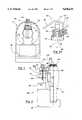
- FIG. 1is a frontal view of the spray misting device and portable fan according to a first preferred embodiment of the present invention
- FIG. 2is a side view of the preferred embodiment shown in FIG. 1;
- FIG. 3is a frontal view of the spray misting device and portable fan according to a second preferred embodiment of the present invention
- FIG. 4is a side view of the preferred embodiment shown in FIG. 3;
- FIG. 5is a frontal view of the spray misting device and portable fan according to a third preferred embodiment of the present invention.
- FIG. 6is a side view of the preferred embodiment shown in FIG. 5;
- FIG. 6ais a sectional view of an alternate spray applicator according to the present invention.
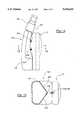
- FIG. 7is a frontal view of the spray misting device and portable fan according to a fourth preferred embodiment of the present invention.
- FIG. 8is a side view of the preferred embodiment shown in FIG. 7;
- FIG. 9is a frontal view of the spray misting device and portable fan according to a fifth preferred embodiment of the present invention.
- FIG. 10is a side view of the preferred embodiment shown in FIG. 9;
- FIG. 11is a cutaway view taken along line 11--11 of FIG. 10 and showing a cross sectional outline of the portable misting device and fan according to the fifth preferred embodiment of the present invention
- FIG. 12is a frontal view of the spray misting device and portable fan according to a sixth preferred embodiment of the present invention.
- FIG. 13is a side view of the preferred embodiment shown in FIG. 12;
- FIG. 14is a side view of a spray misting device and portable fan according to a seventh preferred embodiment of the present invention.
- FIG. 15is a cutaway view taken along line 14--14 of FIG. 14 and showing a cross-section of the mounting means on the body for securing to the fan.
- a combination spray misting device and portable fan 10is shown according to a first preferred embodiment of the present invention.
- a fan 12 of the combinationis shown and is constructed of a generally rectangular shaped outline.
- the fan body 12can however be shaped in any manner desired and, according to FIG. 2, includes a front 14, a rear 16 separated from the front by a predetermined thickness and a fan blade unit 18 housed between a front grille 20 and a rear grille 22 of the fan body 12.
- the fan blade unit 18draws air in through the rear grille 22 and expels the air in an accelerated stream through the front grille 22.
- a portable battery supplysuch as a pair of AA volt batteries 24 are connected to a small electric motor 26 of conventional design by an actuated line 28.
- an A/C adapter jackmay attach to an input plug in the portable fan (not shown) for providing power to the fan.
- An on/off button 30(see FIG. 1) is activated to close a circuit established between the battery supply and the motor and causes the motor to operate the fan blade unit.
- a spray misting device 32includes a body having an outline with a supporting base 36, a narrowed and contoured midsection 38 and an outlet 40.
- the base 36 of the misting device 32may be shaped at a forward end thereof 39 to receive and support the portable fan 12 thereupon so as to give the body of the device a generally L-shape as seen from the cross section of FIG. 2.
- the midsection 38, as seen from FIG. 1,is contoured in a grip design to facilitate handling by a user.
- the device 32is further constructed of a durable plastic or like material that can be easily and inexpensively fabricated and has a hollow interior capable of holding a predetermined volume of a liquid, such as water.
- a screw cap 42attaches over the outlet 40 and may be selectively screwed or unscrewed to the spray device when it is desirable to add more water to the device 32.
- the ergonomic shape of the midsection 38 in combination with the enlarged base 36 of the bodyfacilitates ease of carrying and handling by a user of the device while still providing adequate fluid carrying capability.
- An applicator 44is mounted to the outlet 40 of the body for generating a misting and atomized spray of the fluid contained in the body.
- the applicator 44includes a stem 46 which extends through a central aperture in the screw cap, past the outlet, and down into the interior of the misting body.
- An applicator body 48is integrally mounted with the screw cap 42 and includes an internal channel 50 which fluidly connects to the stem 46.
- a spray ball 52extends from the applicator body 48 and is connected to the internal channel 50 by an input 54.
- the spray ball 52is of a type conventionally known and used with perfume sprays and the like and has a hollowed interior which, upon squeezing of the ball, expels fluid through nozzle 60 and upon release creates a vacuum in the stem 46 to draw fluid upwardly from the misting container.
- the spray ballmay also be constructed of a hemispherical diaphragm (not shown).
- a flexible outlet tube 58is connected to the internal channel 50 at an end opposite the input 54 and extends upwardly and forwardly of the applicator in a direction towards the fan. The outlet tube terminates in the nozzle portion 60 which is mounted within an aperture 62 (see FIG. 1) at a top center position of the fan body 12 at the rear 16 of the fan.
- a mounting bracket 64is provided for releasably securing the misting device 32 to the rear face 16 of the fan.
- the bracketis substantially arcuate shaped along a forward face thereof and is integrally formed to extend from a forward edge of the applicator body 48.
- An upper mounting prong 66 and a lower mounting prong 68extend forwardly from the arcuately shaped bracket and are received in a pair of corresponding upper and lower apertures formed in the rear of the fan body to releasably affix the misting device to the fan.
- the upper and lower prongsare sized to provide a satisfactory snap fit within the fan apertures. While the preferred embodiment of FIGS.
- FIG. 1 and 2show a mounting bracket for securing the misting device to the fan, it is understood that any alternative type of structure can be used in place of the mounting bracket for releasably securing the misting unit in place.
- the mounting bracketis shown as having an arc shape, it can also be provided as a flat shaped bracket to correspond to a flat mounting surface on the fan body, such as the outside of the motor enclosure on the rear face which is usually flattened but cannot be seen from the drawings.
- the misting deviceis mounted to the fan body as previously described, the device having been prefilled with a desired fluid such as water and the screw cap tightened in place.
- the portable fanmay or may not be operating prior to engaging the misting device but, in the preferred embodiment, is activated to the on position.
- the squeeze ball 52is then depressed and released in order to expel a measured volume of fluid from the reservoir within the misting device, through the stem 46, the internal channel 50 in the applicator body, the outlet tube 58, and into the nozzle 60 positioned atop the fan body.
- the nozzleis constructed so that the fluid is discharged as a finely atomized spray, as seen as 65 in FIG. 2, in a direction from above and in front of the front grille 20 of the fan.
- the spray 64will descend downwardly in front of an accelerated current of air generated by the fan and will be cooled by evaporation and subsequently dispersed outwardly in a direction chosen by the user.
- the vacuum created by the pump balldraws fluid up through the stem out of the reservoir.
- a small ball bearing 69acts as a check valve to keep fluid from flowing back into the reservoir or air from getting sucked into the pump body.
- the squeeze ballmay be pumped repetitiously to withdraw measured volumes of fluid which are subsequently atomized and cooled by the fan for application to the user. In this manner, the user may determine the amount of spray mist to be applied.
- the nozzlemay also be designed so it may be withdrawn from within the aperture in the fan and the misting device separated from the fan by the mounting bracket so that it may be separately used purely as a misting device.
- the fanmay also be used separately or in combination with the misting device.
- a combination spray misting device and portable fan 70according to a second preferred embodiment is shown.
- the misting device and fan according to the second preferred embodimentis identical in every respect to that of the first preferred embodiment, with the exception of the shaping of the body of the of a misting device 72.
- the device 72includes a base 74 and a contoured midsection 76 which extends upwardly from the base and which terminates in an outlet 78.
- the base 74 of the second preferred embodiment 70is larger in a vertical dimension relative to the base 36 of the first preferred embodiment 10, the midsection 76 being of a correspondingly smaller dimension with fewer ergonomically shaped grooves to compensate for the enlarged base 74.
- the body of the misting device according to the second preferred embodimentis intended to provide for additional fluid holding capacity above that permitted by the body of the first preferred embodiment while still providing an ergonomically usable device which may be easily gripped and operated by a user.
- the combination misting device and fan 70otherwise operates in an identical fashion to that disclosed in the first embodiment.
- a body 82 of the misting deviceis shaped similarly to the corresponding misting devices of the first and second preferred embodiments and includes a base 84 and a contoured midsection 86 which terminates in an outlet 88.
- the base 84is approximate in dimension to the base 74 of the second preferred embodiment, however the midsection 86 is larger than in either the first and second embodiments so that the misting device body has a substantially greater height relative to the fan 12.
- a stem 90extends upwardly from within the interior of the misting device body, through the outlet 88 and a screw cap 92 attached over the outlet, and into an applicator body 94 which is integrally formed with the screw cap 92.
- a piston pump head 96extends from the applicator body 94 and is fluidly connected to an internal channel 98 formed in the applicator body by a shaft portion connected to an input 100 of the applicator body.
- the internal channel 98is fluidly connected at an opposite end to an outlet tube 102 similar to that disclosed in the first and second preferred embodiments.
- the outlet tube 102terminates in a nozzle 104 which is mounted within an aperture 106 (see FIG. 5) facing forwardly at a top central point in the front of the fan body.
- the pump head 96is similar in respects to the spray ball 52 of the first and second embodiments and, upon being depressed in a direction toward the applicator body, will create a pumping action to withdraw fluid from the receptacle.
- the pump headis repetitively depressed to withdraw measured volumes of fluid from within the receptacle and issue the fluid as a misted and atomized spray from the nozzle.
- a trigger arm 95may alternatively be used for actuating a spray pump applicating head 97.
- the spray pump head 97is similar to the head 96 shown in FIG. 6, with the exception that it has a rounded upper surface for being contacted and depressed downwardly by the trigger arm 95.
- the trigger arm 95is hingedly connected to the applicator body 94 and includes first and second angled portions 99 and 101 and a downwardly extending portion 103 which terminates in the hinged connection 99. In use, the angled portion 99 is depressed downwardly so that the portion 101 biases downwardly against the spray head to cause the spray head to issue the atomized mist spray.
- a mounting bracket 108is provided for releasably securing the misting device to the fan.
- the bracket 108is similar in regards to the bracket shown in the earlier preferred embodiments, with the exception that it is larger in cross section and extends from the applicator body at a higher point relative to the rear of the fan.
- An upper mounting prong 110 and a lower mounting prong 112extend from the mounting bracket and are secured within their associated recesses in the rear face of the fan as previously described to mount the fan to the misting device.
- a body 116 of the misting deviceincludes a base 118 which, similarly to the first, second and third preferred embodiments, has a width approximate to that of the fan body and which provides added stability to the fan body.
- a contoured an upwardly extending middle 120extends from the base (see contours in FIG. 7) and terminates in a neck portion 122.
- the body of the misting deviceholds a predetermined volume of fluid.
- An applicator body 124is threadably attached to the open neck of the misting body as is conventionally known and terminates in a spray pump head 126 which is connected to the applicator body 124 through an intermediate portion 128.
- a cap 130is attached over the pump head 126 for when the device is not in use.
- the design and construction of the spray pump head 126is well known in the art and, upon being depressed relative to the intermediate portion 128, causes fluid to be withdrawn from the within the misting body through a stem extending downwardly into the receptacle body (not shown in this embodiment) and issued as an atomized mist spray from an opening 132 in the pump head.
- the pump headis positioned above and behind the fan blade unit of the fan and the resultant spray travel over the fan and descends in front for cooling and dispersal by the air currents generated by the fan blade unit as previously described.
- the spray applicating means of the fourth preferred embodimentas with embodiments one through three, provides for more efficient and thorough spray distribution in combination with the fan and permits a user to derive the same level of cooling comfort with lesser volumes of fluid than is required with prior art misting devices.
- a mounting bracket 134is provided for releasably securing the misting device 116 to the fan 12.
- the bracket 134includes a pair of rearwardly extending clip portions 136 which insert within associated grooves 138 formed in the sides of the contoured middle portion 120 of the misting device body.
- the bracketis arcuately shaped along a front face 140 thereof to correspond with and abut against the rear of the fan body.
- An upper prong 142 and a lower prong 144extend forwardly from the bracket as described in the previous embodiments and insert within associated apertures formed in the rear face of the fan to releasably mount the fan to the misting device.
- a body 148 of the misting deviceis similar in respects to the body 116 disclosed in FIGS. 7 and 8 and includes a base 150 and an upwardly extending midsection 152.
- the midsection 152is inwardly recessed in a forward direction on both sides 154 so that the misting body is easier to grip by the user.
- the body 148is contoured in a generally arcuate manner so that a forward surface 156 of the body is contoured to match the rear surface of the portable fan and so that a spray pump head 158 is tilted forwardly and downwardly to a point directly in front of the fan blade unit.
- the spray pump head 158is successively depressed to issue the atomized mist spray in a direction downwardly and directly in front of the fan blade unit and does not rely upon the effects of gravity as in the embodiment of FIGS. 7 and 8 to position the spray in front of the fan unit.
- a mounting bracket 160is provided for mounting the misting device to the fan and includes a spring clip 162 which attaches within an associated recess in the recessed sides 154 of the body midsection.
- the spring clip 162is attached to the mounting bracket 160 in a press fit manner and the bracket 160 in turn has the forwardly extending prongs 164 and 166 which secure within the associated recesses in the fan.
- the spring clip 162has a generally U-shape in cross section and fastens about a generally T-shaped forward protrusion 165 of the body. Also, the contour of the sides 154 allows greater airflow through the rear and front grilles of the fan body.
- a recess 168is formed in an upper portion of the mounting bracket and may receive a lanyard or other string or rope for securing the combination misting device and fan about the neck of the user. While evident only from the embodiment of FIGS. 9-11, a lanyard loop may also be formed through either the mounting brackets or any other part of the combination misting device or fan for receiving a string or rope for suspending the device around the neck of a user.
- the misting deviceincludes a body 172 of a substantially uniform shape and cross section and a spray pump head 174 of a type previously described which is mounted atop an outlet 176 of the body 172 and is held in place above a sealing collar 178.
- the body 172 of the sixth preferred embodimentdiffers from the earlier embodiments in that it is constructed of a flexible and soft waterproof material which will successively collapse as the fluid carrying reservoir within body is used up.
- a reservoir support 180forms an integral part of a mounting bracket 184 extends along the rear face of the portable fan 12 and supports a bottom surface of the flexible body to prevent the fluid filled reservoir from swinging back and forth while in use.
- the reservoir support 180is secured to the mounting bracket by a circular spring element 182 which biasingly encourages the support 180 in a clockwise rotational direction 186 as indicated in FIG. 12 as the reservoir is emptied.
- the flexible body 172is shown in a completely drained position in which all of the fluid and air have been evacuated from its interior and it abuts flush against the face of the mounting bracket.
- the biasing forces generated by the spring 182causes the support 180 to be completely rotated to a flush position against the side of the mounting bracket and provides a space saving convenience to the device.
- a screw top support 186is integrally formed with the mounting bracket 184 at a second higher position above the support 180 and supports the pump spray head in place after the contents of the body have been evacuated.
- the fastening headcan be rotatably disattached from the screw top support and a fluid supply can be provided to refill the device, causing the body to resume its original and filled shape and the support 180 rotated back to its original outwardly biases position.
- the mounting bracket 184 of the sixth preferred embodimentis generally larger as opposed to the earlier embodiments for the specific purpose of separately supporting the pump spray head and the lower pivotal support.
- a first inwardly directed prong 188 and a second inwardly directed prong 190are provided for mounting the bracket to the rear face of the fan as previously described.
- the misting deviceincludes a body 196 which is shaped substantially identical to that shown in the embodiment of FIGS. 10 and 11 and includes a body with a forwardly angles midsection terminating in a spray pump head 198 which is tilted in a direction forwardly and downwardly in front of the fan blade unit of the portable fan.
- the midsection of the misting device bodyincludes a pair of inwardly recessed sidewalls 200 as shown from the cross section of FIG. 15 which terminates in a central point 202.
- FIGS. 14 and 15replaces the mounting bracket shown in the earlier embodiments in that a first upper barbed prong 204 and a second lower barbed prong 206 are integrally formed with and extend forwardly from the body of the misting device.
- the barbed prongsinsert within the apertures formed in the rear face of the fan body as previously disclosed. Accordingly, the barbed prongs replace the mounting bracket and provide a direct connection between the misting device and the fan unit.
- the present inventiontherefore teaches a novel and useful portable misting device and fan which is an improvement over other misting devices and which is portable and highly effective for use by individuals participating in athletic or other outdoor activities.
- the present inventionalso provides a combination portable fan and misting device which may be used separably or in combination as desired by the user.
- misting bottle shapes and sizesmay be employed with the fan, provided the necessary mounting bracketry is provided for attaching the misting device to the fan.
- Other types of fastenersmay be provided for attaching the misting device to the spray applicator, such as pressure fit elements for inserting into the body outlet of the device or overtravel clamps for securing around a neck of the body.
- Other kinds of spray applicatorsmay alternatively be used with the misting device.
- the fanmay also be shaped as desired to correspond with an appropriately shaped misting device.
Landscapes
- Chemical & Material Sciences (AREA)
- Chemical Kinetics & Catalysis (AREA)
- Structures Of Non-Positive Displacement Pumps (AREA)
- Containers And Packaging Bodies Having A Special Means To Remove Contents (AREA)
Abstract
Description
Claims (18)
Priority Applications (3)
| Application Number | Priority Date | Filing Date | Title |
|---|---|---|---|
| US08/516,388US5620633A (en) | 1995-08-17 | 1995-08-17 | Spray misting device for use with a portable-sized fan |
| PCT/US1996/013288WO1997006882A1 (en) | 1995-08-17 | 1996-08-16 | Portable spray misting device with fan |
| US08/808,402US5843344A (en) | 1995-08-17 | 1997-02-28 | Portable fan and combination fan and spray misting device |
Applications Claiming Priority (1)
| Application Number | Priority Date | Filing Date | Title |
|---|---|---|---|
| US08/516,388US5620633A (en) | 1995-08-17 | 1995-08-17 | Spray misting device for use with a portable-sized fan |
Related Child Applications (1)
| Application Number | Title | Priority Date | Filing Date |
|---|---|---|---|
| US08/808,402Continuation-In-PartUS5843344A (en) | 1995-08-17 | 1997-02-28 | Portable fan and combination fan and spray misting device |
Publications (1)
| Publication Number | Publication Date |
|---|---|
| US5620633Atrue US5620633A (en) | 1997-04-15 |
Family
ID=24055359
Family Applications (2)
| Application Number | Title | Priority Date | Filing Date |
|---|---|---|---|
| US08/516,388Expired - LifetimeUS5620633A (en) | 1995-08-17 | 1995-08-17 | Spray misting device for use with a portable-sized fan |
| US08/808,402Expired - LifetimeUS5843344A (en) | 1995-08-17 | 1997-02-28 | Portable fan and combination fan and spray misting device |
Family Applications After (1)
| Application Number | Title | Priority Date | Filing Date |
|---|---|---|---|
| US08/808,402Expired - LifetimeUS5843344A (en) | 1995-08-17 | 1997-02-28 | Portable fan and combination fan and spray misting device |
Country Status (2)
| Country | Link |
|---|---|
| US (2) | US5620633A (en) |
| WO (1) | WO1997006882A1 (en) |
Cited By (38)
| Publication number | Priority date | Publication date | Assignee | Title |
|---|---|---|---|---|
| US5740948A (en)* | 1997-02-03 | 1998-04-21 | Chu; Wei-Yieh | Multi-functional compound integrated bottle |
| US5843344A (en)* | 1995-08-17 | 1998-12-01 | Circulair, Inc. | Portable fan and combination fan and spray misting device |
| DE19729260A1 (en)* | 1997-07-09 | 1999-01-14 | Gerhard Zehdnicker | Fog-making device |
| US5965067A (en)* | 1995-09-01 | 1999-10-12 | Circulair, Inc. | Portable fan device for use with a spray misting bottle |
| US6216961B1 (en) | 1999-05-12 | 2001-04-17 | Misty Mate Inc | Fan propelled mister |
| US6217294B1 (en)* | 1999-02-16 | 2001-04-17 | Terry E. Arnieri | Combination container with mounted fan |
| US6237896B1 (en) | 1999-10-22 | 2001-05-29 | Ricky D. Hicks | Portable fan with misting nozzles |
| US6325362B1 (en) | 1999-05-26 | 2001-12-04 | Raymond O. Massey | Cooling and misting apparatus for evaporative cooling of open-air vehicle occupants |
| US6378845B1 (en)* | 2000-10-02 | 2002-04-30 | Chin-Tien Hsu | Portable combination fan and humidifier |
| US6398132B1 (en) | 1999-04-12 | 2002-06-04 | Circulair, Inc. | Cooling device using fan-driven misting with large fill and drinking port |
| US20020148909A1 (en)* | 1999-04-12 | 2002-10-17 | Junkel Eric F. | Cooling device using fan-driven misting with large bottom fill port |
| US6588372B1 (en)* | 2001-09-28 | 2003-07-08 | Michael E. Terrell | Gear drive livestock fan |
| US20040089745A1 (en)* | 2002-11-07 | 2004-05-13 | Zimmerman Robert P. | Side handle mist sprayer |
| US20050106018A1 (en)* | 2003-11-17 | 2005-05-19 | Ed Stengel | Necklace fan |
| US20050150976A1 (en)* | 2004-01-12 | 2005-07-14 | Ed Stengel | Portable spray fan |
| US20050279854A1 (en)* | 2004-06-17 | 2005-12-22 | S.C. Johnson & Son, Inc. | Liquid atomizing device with reduced settling of atomized liquid droplets |
| US20060162349A1 (en)* | 2003-11-03 | 2006-07-27 | Edwards Tim L | Heat exhaustion evaporative cooling |
| US20060185627A1 (en)* | 2005-02-22 | 2006-08-24 | Green Michael P | Radiator and air cooler mister |
| US20060273195A1 (en)* | 2005-06-03 | 2006-12-07 | Eric Junkel | Portable misting fan with closely integrated pump |
| US7150162B1 (en)* | 2005-09-06 | 2006-12-19 | Brunner Tracy D | Stroller with misting system |
| USD544078S1 (en) | 2005-06-03 | 2007-06-05 | Brookstone Purchasing, Inc. | Fan with misting capability |
| USD546194S1 (en) | 2006-02-06 | 2007-07-10 | Shimon Silberfenig | Packaging for dispensing a fluid |
| USD554242S1 (en) | 2006-08-10 | 2007-10-30 | Glj, Llc | Misting fan |
| US20080047291A1 (en)* | 2006-08-25 | 2008-02-28 | Wind Merchants Ip, Llc. | Personal or spot area environmental management systems and apparatuses |
| US20080169575A1 (en)* | 2007-01-16 | 2008-07-17 | Yung Chen | Portable misting device |
| US20080237900A1 (en)* | 2007-03-28 | 2008-10-02 | Eric Junkel | Handheld water misting fan with improved air flow |
| US20080237899A1 (en)* | 2007-03-28 | 2008-10-02 | Yung Chen | Break resistant joint |
| US20080244954A1 (en)* | 2007-04-03 | 2008-10-09 | Samuel Shannon | Hunter's Scent Dispersing Apparatus |
| US20090121047A1 (en)* | 2007-11-14 | 2009-05-14 | Stylus, Inc. | Fan spray device |
| US7566048B1 (en) | 2008-09-18 | 2009-07-28 | Stylus, Inc. | Fan spray device |
| US20120130322A1 (en)* | 2000-07-12 | 2012-05-24 | Sharon F. Kleyne | Method and Kit for Moisturizing the Surface of the Eye |
| US20140014740A1 (en)* | 2012-07-16 | 2014-01-16 | Michael Sands | Misting Bottle with Fan |
| US9267698B2 (en) | 2014-02-28 | 2016-02-23 | Techtronic Power Tools Technology Limited | Mister fan |
| US10226037B2 (en) | 2015-03-25 | 2019-03-12 | Clarke Consumer Products, Inc. | Fluid dispensing device |
| US10330333B2 (en)* | 2014-04-29 | 2019-06-25 | Bryan Kaleta | Portable misting fan with pivoting head |
| US11629869B1 (en) | 2022-03-16 | 2023-04-18 | Ontel Products Corporation | Personal air cooler |
| USD1018822S1 (en) | 2022-03-16 | 2024-03-19 | Ontel Products Corporation | Portable air cooler |
| USD1018821S1 (en) | 2022-03-16 | 2024-03-19 | Ontel Products Corporation | Portable air cooler |
Families Citing this family (90)
| Publication number | Priority date | Publication date | Assignee | Title |
|---|---|---|---|---|
| US6161777A (en)* | 1997-08-08 | 2000-12-19 | C. Michael Carter | Portable spraying and drinking apparatus |
| US6440190B1 (en)* | 2000-08-16 | 2002-08-27 | Michael E. Goyetche | Portable exhaust fan for removing airborne hazardous materials |
| US20070077140A1 (en)* | 2005-10-03 | 2007-04-05 | Shimon Silberfenig | Packaging for dispensing a fluid |
| US20080069694A1 (en)* | 2006-09-19 | 2008-03-20 | Hector Ray Hernandez | Electric fan |
| GB0814835D0 (en) | 2007-09-04 | 2008-09-17 | Dyson Technology Ltd | A Fan |
| US8162293B2 (en)* | 2007-10-31 | 2012-04-24 | Richard Goldmann | Device for applying cooling mist and dry air to individuals |
| GB2463698B (en) | 2008-09-23 | 2010-12-01 | Dyson Technology Ltd | A fan |
| GB2464736A (en) | 2008-10-25 | 2010-04-28 | Dyson Technology Ltd | Fan with a filter |
| US7878424B2 (en)* | 2008-11-20 | 2011-02-01 | Disney Enterprises, Inc. | Personal misting device with manually-operated and retractable folding fan |
| CN202056982U (en)* | 2009-03-04 | 2011-11-30 | 戴森技术有限公司 | Humidifying device |
| GB2468317A (en) | 2009-03-04 | 2010-09-08 | Dyson Technology Ltd | Height adjustable and oscillating fan |
| GB2468323A (en) | 2009-03-04 | 2010-09-08 | Dyson Technology Ltd | Fan assembly |
| NZ593318A (en) | 2009-03-04 | 2012-11-30 | Dyson Technology Ltd | An annular fan assembly with a silencing member |
| PL2276933T3 (en) | 2009-03-04 | 2011-10-31 | Dyson Technology Ltd | A fan |
| GB2468329A (en) | 2009-03-04 | 2010-09-08 | Dyson Technology Ltd | Fan assembly |
| GB2468331B (en) | 2009-03-04 | 2011-02-16 | Dyson Technology Ltd | A fan |
| GB2468315A (en) | 2009-03-04 | 2010-09-08 | Dyson Technology Ltd | Tilting fan |
| GB2468326A (en) | 2009-03-04 | 2010-09-08 | Dyson Technology Ltd | Telescopic pedestal fan |
| GB0903682D0 (en) | 2009-03-04 | 2009-04-15 | Dyson Technology Ltd | A fan |
| KR101395177B1 (en) | 2009-03-04 | 2014-05-15 | 다이슨 테크놀러지 리미티드 | A fan |
| GB2468322B (en) | 2009-03-04 | 2011-03-16 | Dyson Technology Ltd | Tilting fan stand |
| GB2468312A (en) | 2009-03-04 | 2010-09-08 | Dyson Technology Ltd | Fan assembly |
| GB2468320C (en) | 2009-03-04 | 2011-06-01 | Dyson Technology Ltd | Tilting fan |
| CN201425031Y (en) | 2009-04-16 | 2010-03-17 | 麦志坚 | Blowing fan with water mist function |
| US8123290B1 (en) | 2009-06-17 | 2012-02-28 | BreezzAngel, LLC | Portable cooling device |
| GB0919473D0 (en) | 2009-11-06 | 2009-12-23 | Dyson Technology Ltd | A fan |
| GB2478927B (en) | 2010-03-23 | 2016-09-14 | Dyson Technology Ltd | Portable fan with filter unit |
| GB2478925A (en) | 2010-03-23 | 2011-09-28 | Dyson Technology Ltd | External filter for a fan |
| USD629066S1 (en)* | 2010-04-28 | 2010-12-14 | Way2Cool, Inc. | Personal misting device |
| SG186071A1 (en) | 2010-05-27 | 2013-01-30 | Dyson Technology Ltd | Device for blowing air by means of narrow slit nozzle assembly |
| GB2482547A (en) | 2010-08-06 | 2012-02-08 | Dyson Technology Ltd | A fan assembly with a heater |
| GB2482549A (en) | 2010-08-06 | 2012-02-08 | Dyson Technology Ltd | A fan assembly with a heater |
| GB2482548A (en) | 2010-08-06 | 2012-02-08 | Dyson Technology Ltd | A fan assembly with a heater |
| GB2483448B (en) | 2010-09-07 | 2015-12-02 | Dyson Technology Ltd | A fan |
| JP5588565B2 (en) | 2010-10-13 | 2014-09-10 | ダイソン テクノロジー リミテッド | Blower assembly |
| EP2630373B1 (en) | 2010-10-18 | 2016-12-28 | Dyson Technology Limited | A fan assembly |
| GB2484670B (en) | 2010-10-18 | 2018-04-25 | Dyson Technology Ltd | A fan assembly |
| JP5778293B2 (en) | 2010-11-02 | 2015-09-16 | ダイソン テクノロジー リミテッド | Blower assembly |
| GB2486019B (en) | 2010-12-02 | 2013-02-20 | Dyson Technology Ltd | A fan |
| US8794599B2 (en)* | 2011-04-18 | 2014-08-05 | Greg Steiner | Manual misting fan |
| US9022360B2 (en)* | 2011-04-18 | 2015-05-05 | Gregory Steiner | Manual misting fan |
| BR112014001474A2 (en) | 2011-07-27 | 2017-02-21 | Dyson Technology Ltd | fan assembly |
| GB2493506B (en) | 2011-07-27 | 2013-09-11 | Dyson Technology Ltd | A fan assembly |
| GB201119500D0 (en) | 2011-11-11 | 2011-12-21 | Dyson Technology Ltd | A fan assembly |
| GB2496877B (en) | 2011-11-24 | 2014-05-07 | Dyson Technology Ltd | A fan assembly |
| GB2498547B (en) | 2012-01-19 | 2015-02-18 | Dyson Technology Ltd | A fan |
| GB2499042A (en) | 2012-02-06 | 2013-08-07 | Dyson Technology Ltd | A nozzle for a fan assembly |
| GB2499041A (en) | 2012-02-06 | 2013-08-07 | Dyson Technology Ltd | Bladeless fan including an ionizer |
| GB2499044B (en) | 2012-02-06 | 2014-03-19 | Dyson Technology Ltd | A fan |
| GB2500010B (en)* | 2012-03-06 | 2016-08-24 | Dyson Technology Ltd | A humidifying apparatus |
| GB2512192B (en) | 2012-03-06 | 2015-08-05 | Dyson Technology Ltd | A Humidifying Apparatus |
| RU2606194C2 (en) | 2012-03-06 | 2017-01-10 | Дайсон Текнолоджи Лимитед | Fan unit |
| GB2500011B (en) | 2012-03-06 | 2016-07-06 | Dyson Technology Ltd | A Humidifying Apparatus |
| GB2500017B (en) | 2012-03-06 | 2015-07-29 | Dyson Technology Ltd | A Humidifying Apparatus |
| GB2500012B (en) | 2012-03-06 | 2016-07-06 | Dyson Technology Ltd | A Humidifying Apparatus |
| GB2500903B (en) | 2012-04-04 | 2015-06-24 | Dyson Technology Ltd | Heating apparatus |
| GB2501301B (en) | 2012-04-19 | 2016-02-03 | Dyson Technology Ltd | A fan assembly |
| GB2532557B (en) | 2012-05-16 | 2017-01-11 | Dyson Technology Ltd | A fan comprsing means for suppressing noise |
| EP2850324A2 (en) | 2012-05-16 | 2015-03-25 | Dyson Technology Limited | A fan |
| GB2518935B (en) | 2012-05-16 | 2016-01-27 | Dyson Technology Ltd | A fan |
| GB2503907B (en) | 2012-07-11 | 2014-05-28 | Dyson Technology Ltd | A fan assembly |
| BR302013003358S1 (en) | 2013-01-18 | 2014-11-25 | Dyson Technology Ltd | CONFIGURATION APPLIED ON HUMIDIFIER |
| AU350181S (en) | 2013-01-18 | 2013-08-15 | Dyson Technology Ltd | Humidifier or fan |
| AU350179S (en) | 2013-01-18 | 2013-08-15 | Dyson Technology Ltd | Humidifier or fan |
| AU350140S (en) | 2013-01-18 | 2013-08-13 | Dyson Technology Ltd | Humidifier or fan |
| SG11201505665RA (en) | 2013-01-29 | 2015-08-28 | Dyson Technology Ltd | A fan assembly |
| GB2510195B (en) | 2013-01-29 | 2016-04-27 | Dyson Technology Ltd | A fan assembly |
| USD729372S1 (en) | 2013-03-07 | 2015-05-12 | Dyson Technology Limited | Fan |
| CA152655S (en) | 2013-03-07 | 2014-05-20 | Dyson Technology Ltd | Fan |
| CA152656S (en) | 2013-03-07 | 2014-05-20 | Dyson Technology Ltd | Fan |
| CA152658S (en) | 2013-03-07 | 2014-05-20 | Dyson Technology Ltd | Fan |
| CA152657S (en) | 2013-03-07 | 2014-05-20 | Dyson Technology Ltd | Fan |
| BR302013004394S1 (en) | 2013-03-07 | 2014-12-02 | Dyson Technology Ltd | CONFIGURATION APPLIED TO FAN |
| GB2516058B (en) | 2013-07-09 | 2016-12-21 | Dyson Technology Ltd | A fan assembly with an oscillation and tilt mechanism |
| TWD172707S (en) | 2013-08-01 | 2015-12-21 | 戴森科技有限公司 | A fan |
| CA154722S (en) | 2013-08-01 | 2015-02-16 | Dyson Technology Ltd | Fan |
| CA154723S (en) | 2013-08-01 | 2015-02-16 | Dyson Technology Ltd | Fan |
| CN103410747A (en)* | 2013-08-19 | 2013-11-27 | 樊书印 | Fan |
| CN103410788B (en)* | 2013-08-19 | 2015-10-28 | 樊书印 | A kind of fan |
| GB2518638B (en) | 2013-09-26 | 2016-10-12 | Dyson Technology Ltd | Humidifying apparatus |
| US20150285598A1 (en)* | 2014-04-02 | 2015-10-08 | Michael Flynn | Dual Purpose Self-Defense Device |
| GB2528709B (en) | 2014-07-29 | 2017-02-08 | Dyson Technology Ltd | Humidifying apparatus |
| GB2528704A (en) | 2014-07-29 | 2016-02-03 | Dyson Technology Ltd | Humidifying apparatus |
| GB2528708B (en) | 2014-07-29 | 2016-06-29 | Dyson Technology Ltd | A fan assembly |
| USD770022S1 (en)* | 2015-03-06 | 2016-10-25 | O2Cool, Llc | Water misting fan |
| USD767747S1 (en)* | 2015-03-23 | 2016-09-27 | Connie Wang | Handheld fan |
| CN106152355A (en)* | 2015-07-29 | 2016-11-23 | 洛阳新巨能高热技术有限公司 | A kind of Novel atomizing device |
| US20170198703A1 (en)* | 2016-01-13 | 2017-07-13 | Jeff Leitman | Fan Powered by Mobile Device |
| US11358167B2 (en)* | 2020-01-22 | 2022-06-14 | Elc Management Llc | Reusable pump dispenser |
| US11466894B1 (en) | 2021-08-06 | 2022-10-11 | Tyler Perrelle | Compact orientation-adjustable mister-fan apparatus |
Citations (18)
| Publication number | Priority date | Publication date | Assignee | Title |
|---|---|---|---|---|
| US2351226A (en)* | 1943-09-27 | 1944-06-13 | William P Pernhall | Atomizer |
| US2608792A (en)* | 1949-09-09 | 1952-09-02 | Fmc Corp | Moistened dust spraying machine |
| US2736606A (en)* | 1953-09-11 | 1956-02-28 | Thomas E Kmiotek | Spray gun attachment for portable electric drills |
| US2787501A (en)* | 1956-04-23 | 1957-04-02 | Frank J Tuma | Window cleaning device |
| US2937712A (en)* | 1958-09-22 | 1960-05-24 | James H Woods | Air de-contaminator |
| US3296739A (en)* | 1965-02-17 | 1967-01-10 | B L Johnson | Rotating orchard heater |
| US3659791A (en)* | 1969-11-17 | 1972-05-02 | William O Clark | Spray gun adaptor for aerosal cans |
| US3734357A (en)* | 1971-09-10 | 1973-05-22 | N Batistelli | Portable holder for pressurized containers |
| US3997115A (en)* | 1976-03-10 | 1976-12-14 | Lawrence Peska Associates, Inc. | Portable atomizer for liquids |
| USD264181S (en) | 1980-05-02 | 1982-05-04 | Booso Carol A | Combined bottle and brush |
| US4399794A (en)* | 1981-10-29 | 1983-08-23 | Gagnon David C | Carburetion system |
| US4523080A (en)* | 1983-03-14 | 1985-06-11 | Bolton John D | Apparatus for treatment of hair and scalp |
| US4700494A (en)* | 1986-09-15 | 1987-10-20 | Pridgen Danny W | Apparatus for drying hair spray and other compositions |
| USD292556S (en) | 1984-08-06 | 1987-11-03 | Tannies Corporation | Bottle |
| US4839106A (en)* | 1988-05-12 | 1989-06-13 | Gregory A. Steiner | Portable misting fan |
| US4911361A (en)* | 1987-02-05 | 1990-03-27 | Atsushi Tada | Manually operated trigger type dispenser, method of assembling the same, and a spinner for use in the dispenser |
| USD349570S (en) | 1993-07-20 | 1994-08-09 | Circulair, Inc. | Small electric fan |
| US5338495A (en)* | 1993-10-18 | 1994-08-16 | Innovative Design Enterprises | Portable misting fan |
Family Cites Families (8)
| Publication number | Priority date | Publication date | Assignee | Title |
|---|---|---|---|---|
| US1993635A (en)* | 1933-08-08 | 1935-03-05 | Towt Charles Warren | Apparatus for preventing damage to vegetation by frosting and sunburning temperatures |
| US2079117A (en)* | 1936-09-05 | 1937-05-04 | Russell R Hays | Atomizing fan |
| US4235377A (en)* | 1978-11-29 | 1980-11-25 | The Wooster Brush Company | Portable paint spraying device |
| US5082177A (en)* | 1990-01-31 | 1992-01-21 | Hill Daryl G | Fluid injection spray system |
| US5620633A (en)* | 1995-08-17 | 1997-04-15 | Circulair, Inc. | Spray misting device for use with a portable-sized fan |
| US5667732A (en)* | 1995-08-30 | 1997-09-16 | Lederer; Jeffrey H. | Compact portable misting fan |
| US5667731A (en)* | 1995-09-01 | 1997-09-16 | Circulair, Inc. | Portable fan device for use with a spray misting bottle |
| US5715999A (en)* | 1996-01-30 | 1998-02-10 | Hsu; Chin-Tien | Atomizer |
- 1995
- 1995-08-17USUS08/516,388patent/US5620633A/ennot_activeExpired - Lifetime
- 1996
- 1996-08-16WOPCT/US1996/013288patent/WO1997006882A1/enactiveApplication Filing
- 1997
- 1997-02-28USUS08/808,402patent/US5843344A/ennot_activeExpired - Lifetime
Patent Citations (18)
| Publication number | Priority date | Publication date | Assignee | Title |
|---|---|---|---|---|
| US2351226A (en)* | 1943-09-27 | 1944-06-13 | William P Pernhall | Atomizer |
| US2608792A (en)* | 1949-09-09 | 1952-09-02 | Fmc Corp | Moistened dust spraying machine |
| US2736606A (en)* | 1953-09-11 | 1956-02-28 | Thomas E Kmiotek | Spray gun attachment for portable electric drills |
| US2787501A (en)* | 1956-04-23 | 1957-04-02 | Frank J Tuma | Window cleaning device |
| US2937712A (en)* | 1958-09-22 | 1960-05-24 | James H Woods | Air de-contaminator |
| US3296739A (en)* | 1965-02-17 | 1967-01-10 | B L Johnson | Rotating orchard heater |
| US3659791A (en)* | 1969-11-17 | 1972-05-02 | William O Clark | Spray gun adaptor for aerosal cans |
| US3734357A (en)* | 1971-09-10 | 1973-05-22 | N Batistelli | Portable holder for pressurized containers |
| US3997115A (en)* | 1976-03-10 | 1976-12-14 | Lawrence Peska Associates, Inc. | Portable atomizer for liquids |
| USD264181S (en) | 1980-05-02 | 1982-05-04 | Booso Carol A | Combined bottle and brush |
| US4399794A (en)* | 1981-10-29 | 1983-08-23 | Gagnon David C | Carburetion system |
| US4523080A (en)* | 1983-03-14 | 1985-06-11 | Bolton John D | Apparatus for treatment of hair and scalp |
| USD292556S (en) | 1984-08-06 | 1987-11-03 | Tannies Corporation | Bottle |
| US4700494A (en)* | 1986-09-15 | 1987-10-20 | Pridgen Danny W | Apparatus for drying hair spray and other compositions |
| US4911361A (en)* | 1987-02-05 | 1990-03-27 | Atsushi Tada | Manually operated trigger type dispenser, method of assembling the same, and a spinner for use in the dispenser |
| US4839106A (en)* | 1988-05-12 | 1989-06-13 | Gregory A. Steiner | Portable misting fan |
| USD349570S (en) | 1993-07-20 | 1994-08-09 | Circulair, Inc. | Small electric fan |
| US5338495A (en)* | 1993-10-18 | 1994-08-16 | Innovative Design Enterprises | Portable misting fan |
Cited By (52)
| Publication number | Priority date | Publication date | Assignee | Title |
|---|---|---|---|---|
| US5843344A (en)* | 1995-08-17 | 1998-12-01 | Circulair, Inc. | Portable fan and combination fan and spray misting device |
| US5965067A (en)* | 1995-09-01 | 1999-10-12 | Circulair, Inc. | Portable fan device for use with a spray misting bottle |
| US5740948A (en)* | 1997-02-03 | 1998-04-21 | Chu; Wei-Yieh | Multi-functional compound integrated bottle |
| DE19729260A1 (en)* | 1997-07-09 | 1999-01-14 | Gerhard Zehdnicker | Fog-making device |
| US6217294B1 (en)* | 1999-02-16 | 2001-04-17 | Terry E. Arnieri | Combination container with mounted fan |
| US6398132B1 (en) | 1999-04-12 | 2002-06-04 | Circulair, Inc. | Cooling device using fan-driven misting with large fill and drinking port |
| US20020148909A1 (en)* | 1999-04-12 | 2002-10-17 | Junkel Eric F. | Cooling device using fan-driven misting with large bottom fill port |
| US6216961B1 (en) | 1999-05-12 | 2001-04-17 | Misty Mate Inc | Fan propelled mister |
| US6371388B2 (en) | 1999-05-12 | 2002-04-16 | Misty Mate, Inc. | Fan propelled mister |
| US6325362B1 (en) | 1999-05-26 | 2001-12-04 | Raymond O. Massey | Cooling and misting apparatus for evaporative cooling of open-air vehicle occupants |
| US6237896B1 (en) | 1999-10-22 | 2001-05-29 | Ricky D. Hicks | Portable fan with misting nozzles |
| US20120130322A1 (en)* | 2000-07-12 | 2012-05-24 | Sharon F. Kleyne | Method and Kit for Moisturizing the Surface of the Eye |
| US6378845B1 (en)* | 2000-10-02 | 2002-04-30 | Chin-Tien Hsu | Portable combination fan and humidifier |
| US6588372B1 (en)* | 2001-09-28 | 2003-07-08 | Michael E. Terrell | Gear drive livestock fan |
| US20040089745A1 (en)* | 2002-11-07 | 2004-05-13 | Zimmerman Robert P. | Side handle mist sprayer |
| US6827290B2 (en) | 2002-11-07 | 2004-12-07 | Robert P. Zimmerman | Side handle mist sprayer |
| US20060162349A1 (en)* | 2003-11-03 | 2006-07-27 | Edwards Tim L | Heat exhaustion evaporative cooling |
| US7284381B2 (en) | 2003-11-03 | 2007-10-23 | Emergency Water Solutions, Inc. | Heat exhaustion evaporative cooling |
| US7082775B1 (en) | 2003-11-03 | 2006-08-01 | Emergency Water Solutions, Inc. | Heat exhaustion evaporative cooling |
| US6955524B2 (en) | 2003-11-17 | 2005-10-18 | Vectacor (A Division Of Bonis & Co.) | Necklace fan |
| US20050106018A1 (en)* | 2003-11-17 | 2005-05-19 | Ed Stengel | Necklace fan |
| US7104468B2 (en) | 2004-01-12 | 2006-09-12 | Vectacor (A Division Of Bonis & Company) | Portable spray fan |
| US20050150976A1 (en)* | 2004-01-12 | 2005-07-14 | Ed Stengel | Portable spray fan |
| US20050279854A1 (en)* | 2004-06-17 | 2005-12-22 | S.C. Johnson & Son, Inc. | Liquid atomizing device with reduced settling of atomized liquid droplets |
| US7775459B2 (en) | 2004-06-17 | 2010-08-17 | S.C. Johnson & Son, Inc. | Liquid atomizing device with reduced settling of atomized liquid droplets |
| US20060185627A1 (en)* | 2005-02-22 | 2006-08-24 | Green Michael P | Radiator and air cooler mister |
| US8596556B2 (en)* | 2005-02-22 | 2013-12-03 | Vehicle Enhancement Labs | Radiator and air cooler mister |
| USD544078S1 (en) | 2005-06-03 | 2007-06-05 | Brookstone Purchasing, Inc. | Fan with misting capability |
| US20060273195A1 (en)* | 2005-06-03 | 2006-12-07 | Eric Junkel | Portable misting fan with closely integrated pump |
| US7150162B1 (en)* | 2005-09-06 | 2006-12-19 | Brunner Tracy D | Stroller with misting system |
| USD546194S1 (en) | 2006-02-06 | 2007-07-10 | Shimon Silberfenig | Packaging for dispensing a fluid |
| USD554242S1 (en) | 2006-08-10 | 2007-10-30 | Glj, Llc | Misting fan |
| US20080047291A1 (en)* | 2006-08-25 | 2008-02-28 | Wind Merchants Ip, Llc. | Personal or spot area environmental management systems and apparatuses |
| US8438867B2 (en) | 2006-08-25 | 2013-05-14 | David Colwell | Personal or spot area environmental management systems and apparatuses |
| US20080169575A1 (en)* | 2007-01-16 | 2008-07-17 | Yung Chen | Portable misting device |
| US8016270B2 (en)* | 2007-01-16 | 2011-09-13 | Yung Chen | Portable misting device |
| US20080237900A1 (en)* | 2007-03-28 | 2008-10-02 | Eric Junkel | Handheld water misting fan with improved air flow |
| US7806388B2 (en)* | 2007-03-28 | 2010-10-05 | Eric Junkel | Handheld water misting fan with improved air flow |
| US7810794B2 (en)* | 2007-03-28 | 2010-10-12 | Yung Chen | Break resistant joint |
| US20080237899A1 (en)* | 2007-03-28 | 2008-10-02 | Yung Chen | Break resistant joint |
| US20080244954A1 (en)* | 2007-04-03 | 2008-10-09 | Samuel Shannon | Hunter's Scent Dispersing Apparatus |
| US20090121047A1 (en)* | 2007-11-14 | 2009-05-14 | Stylus, Inc. | Fan spray device |
| US7566048B1 (en) | 2008-09-18 | 2009-07-28 | Stylus, Inc. | Fan spray device |
| US20140014740A1 (en)* | 2012-07-16 | 2014-01-16 | Michael Sands | Misting Bottle with Fan |
| US8893984B2 (en)* | 2012-07-16 | 2014-11-25 | Michael Sands | Misting bottle with fan |
| US9267698B2 (en) | 2014-02-28 | 2016-02-23 | Techtronic Power Tools Technology Limited | Mister fan |
| US10330333B2 (en)* | 2014-04-29 | 2019-06-25 | Bryan Kaleta | Portable misting fan with pivoting head |
| US10226037B2 (en) | 2015-03-25 | 2019-03-12 | Clarke Consumer Products, Inc. | Fluid dispensing device |
| US11311006B2 (en) | 2015-03-25 | 2022-04-26 | Clarke Consumer Products, Inc. | Container for fluid |
| US11629869B1 (en) | 2022-03-16 | 2023-04-18 | Ontel Products Corporation | Personal air cooler |
| USD1018822S1 (en) | 2022-03-16 | 2024-03-19 | Ontel Products Corporation | Portable air cooler |
| USD1018821S1 (en) | 2022-03-16 | 2024-03-19 | Ontel Products Corporation | Portable air cooler |
Also Published As
| Publication number | Publication date |
|---|---|
| WO1997006882A1 (en) | 1997-02-27 |
| US5843344A (en) | 1998-12-01 |
Similar Documents
| Publication | Publication Date | Title |
|---|---|---|
| US5620633A (en) | Spray misting device for use with a portable-sized fan | |
| US5965067A (en) | Portable fan device for use with a spray misting bottle | |
| US5837167A (en) | Compact portable misting fan | |
| US8016270B2 (en) | Portable misting device | |
| US10330333B2 (en) | Portable misting fan with pivoting head | |
| US6216961B1 (en) | Fan propelled mister | |
| US6378845B1 (en) | Portable combination fan and humidifier | |
| US6911010B2 (en) | Heated massager with massaging liquid dispenser | |
| US5740948A (en) | Multi-functional compound integrated bottle | |
| KR200438831Y1 (en) | Portable hydrator | |
| US4861180A (en) | Lotion applicator apparatus with timer | |
| US7104468B2 (en) | Portable spray fan | |
| US9339827B2 (en) | Portable misting fan | |
| US6827290B2 (en) | Side handle mist sprayer | |
| CA2465887A1 (en) | Foam dispenser, housing and storage holder therefor | |
| NZ264246A (en) | Integral portable fan and atomising unit: fan motor in upper chamber; lower chamber has pump, atomising head aligned with fan, and fluid reservoir connector | |
| EP3970861B1 (en) | Sprayer | |
| CA2418405A1 (en) | Paint applicator | |
| US20170209893A1 (en) | Misting device with quick release interchangeable cartridge | |
| US11148155B2 (en) | Spray device | |
| JP2001516273A (en) | Improvement of liquid dispensing device and improvement on liquid dispensing device | |
| JP2010115590A (en) | Atomizer with stand | |
| US20020189125A1 (en) | Foot dryer apparatus | |
| US20080265060A1 (en) | Device and Spray Head for Stomising a Cosmetic Liquid | |
| US20220040355A1 (en) | Wireless disinfection device |
Legal Events
| Date | Code | Title | Description |
|---|---|---|---|
| AS | Assignment | Owner name:CIRCULAIR, INC., ILLINOIS Free format text:ASSIGNMENT OF ASSIGNORS INTEREST;ASSIGNORS:JUNKEL, ERIC F.;USHER, LINDA M.;REEL/FRAME:007679/0778 Effective date:19950816 | |
| STCF | Information on status: patent grant | Free format text:PATENTED CASE | |
| FEPP | Fee payment procedure | Free format text:PAYOR NUMBER ASSIGNED (ORIGINAL EVENT CODE: ASPN); ENTITY STATUS OF PATENT OWNER: SMALL ENTITY | |
| FPAY | Fee payment | Year of fee payment:4 | |
| AS | Assignment | Owner name:GLJ LLC, ILLINOIS Free format text:ASSIGNMENT OF ASSIGNORS INTEREST;ASSIGNOR:CIRCULAIR, INC.;REEL/FRAME:014108/0784 Effective date:20031006 | |
| FEPP | Fee payment procedure | Free format text:PAYOR NUMBER ASSIGNED (ORIGINAL EVENT CODE: ASPN); ENTITY STATUS OF PATENT OWNER: SMALL ENTITY Free format text:PAYER NUMBER DE-ASSIGNED (ORIGINAL EVENT CODE: RMPN); ENTITY STATUS OF PATENT OWNER: SMALL ENTITY | |
| AS | Assignment | Owner name:BANK ONE, ILLINOIS Free format text:SECURITY INTEREST;ASSIGNORS:GLJ, LLC;CIRCULAIR, INC.;REEL/FRAME:015083/0706 Effective date:20031029 | |
| FPAY | Fee payment | Year of fee payment:8 | |
| FPAY | Fee payment | Year of fee payment:12 | |
| AS | Assignment | Owner name:GLJ, LLC, ILLINOIS Free format text:RELEASE BY SECURED PARTY;ASSIGNOR:JPMORGAN CHASE BANK, N.A., THE SUCCESSOR-IN-INTEREST TO BANK ONE, N.A.;REEL/FRAME:027180/0238 Effective date:20111016 | |
| AS | Assignment | Owner name:O2COOL, LLC, ILLINOIS Free format text:ASSIGNMENT OF ASSIGNORS INTEREST;ASSIGNOR:GLJ, LLC;REEL/FRAME:027219/0971 Effective date:20111019 | |
| AS | Assignment | Owner name:THE PRIVATEBANK AND TRUST COMPANY, ILLINOIS Free format text:SECURITY AGREEMENT;ASSIGNOR:O2COOL, LLC;REEL/FRAME:027307/0232 Effective date:20111019 | |
| AS | Assignment | Owner name:O2COOL LLC, ILLINOIS Free format text:RELEASE BY SECURED PARTY;ASSIGNOR:CIBC BANK USA, F/K/A THE PRIVATEBANK AND TRUST COMPANY;REEL/FRAME:049148/0436 Effective date:20181220 |