US5620476A - Implantable medical device having shielded and filtered feedthrough assembly and methods for making such assembly - Google Patents
Implantable medical device having shielded and filtered feedthrough assembly and methods for making such assemblyDownload PDFInfo
- Publication number
- US5620476A US5620476AUS08/565,204US56520495AUS5620476AUS 5620476 AUS5620476 AUS 5620476AUS 56520495 AUS56520495 AUS 56520495AUS 5620476 AUS5620476 AUS 5620476A
- Authority
- US
- United States
- Prior art keywords
- printed conductors
- coupled
- ground
- connector
- improved system
- Prior art date
- Legal status (The legal status is an assumption and is not a legal conclusion. Google has not performed a legal analysis and makes no representation as to the accuracy of the status listed.)
- Expired - Lifetime
Links
Images


Classifications
- A—HUMAN NECESSITIES
- A61—MEDICAL OR VETERINARY SCIENCE; HYGIENE
- A61N—ELECTROTHERAPY; MAGNETOTHERAPY; RADIATION THERAPY; ULTRASOUND THERAPY
- A61N1/00—Electrotherapy; Circuits therefor
- A61N1/18—Applying electric currents by contact electrodes
- A61N1/32—Applying electric currents by contact electrodes alternating or intermittent currents
- A61N1/36—Applying electric currents by contact electrodes alternating or intermittent currents for stimulation
- A61N1/372—Arrangements in connection with the implantation of stimulators
- A61N1/375—Constructional arrangements, e.g. casings
- A61N1/3752—Details of casing-lead connections
- A61N1/3754—Feedthroughs
- H—ELECTRICITY
- H01—ELECTRIC ELEMENTS
- H01R—ELECTRICALLY-CONDUCTIVE CONNECTIONS; STRUCTURAL ASSOCIATIONS OF A PLURALITY OF MUTUALLY-INSULATED ELECTRICAL CONNECTING ELEMENTS; COUPLING DEVICES; CURRENT COLLECTORS
- H01R13/00—Details of coupling devices of the kinds covered by groups H01R12/70 or H01R24/00 - H01R33/00
- H01R13/46—Bases; Cases
- H01R13/52—Dustproof, splashproof, drip-proof, waterproof, or flameproof cases
- H01R13/5202—Sealing means between parts of housing or between housing part and a wall, e.g. sealing rings
Definitions
- the present inventionrelates generally to implantable medical devices, such as cardiac pacemakers, cardioverters and defibrillators, and more particularly, to a wireless feedthrough assembly for connecting electronic circuits within an implantable medical device to the connector top and for providing electric field shielding and filtering.
- Cardiac pacemakers, and other implantable medical devicessuch as cardiac defibrillators, are hermetically packaged to isolate the device from the body environment. Such devices require that electrical signals be passed between the packaged device and its external connectors, without compromising the hermeticity of the package.
- electrical signalsbe passed between the packaged device and its external connectors, without compromising the hermeticity of the package.
- a feedthrough assemblytypically, electrical coupling between the electronic circuits of the implantable device and the external connections provided by a connector assembly mounted outside of the implantable device are provided by a feedthrough assembly.
- the feedthrough assemblyextends through the hermetically sealed outer wall of the device and into the connector assembly so as to couple the electronic circuits within the implantable device to lead-receiving receptacles within the connector assembly.
- Common feedthrough assembliescontain a number of wires equal to the number of electrical paths required for the configuration. The wires are placed in a ceramic sleeve and are sealed and mechanically secured to the sleeve, such as by brazing.
- the ceramic sleeveis secured to a weld ring, such as by brazing, following which the weld ring is integrated into the housing wall of the implantable device, such as by laser welding.
- the resulting feedthrough assemblyhas many individual seals and exposed lengths of wire.
- Feedthrough assemblies of the type describedhave a number of potential problems.
- One such problemresults from the large number of seals required. Because the plurality of wires and the weld ring each require a separate seal, the large number of seals increases the chances of a compromised seal and the resulting loss of hermeticity.
- the exposed wiresact as an antenna for environmental noise sources. Such noise compromises the quality of the signal transmitted, and this can lead to misinterpretation by the implantable device. Additionally, the wires can be damaged by misalignment or bending during handling of the feedthrough assembly.
- the present inventionprovides a feedthrough assembly in which plural wires are eliminated in favor of a single, monolithic structure of elongated configuration which extends through and is hermetically sealed to a sealing device such as a weld ring.
- the weld ringis, in turn, hermetically sealed within the housing wall of the implantable device.
- the monolithic structurecomprises a multilayered structure in which an array of printed conductors provides the connections between the electronic circuits of the implantable device and the lead-receiving receptacles of the connector assembly.
- Electric field shielding of the printed conductorsis provided by a conductive boot surrounding the printed conductors and being coupled to ground.
- the conductive bootmay be provided by printed ground planes on opposite sides of the printed conductors within a multilayered structure. Filtering is provided by capacitors coupled between positive contacts and ground contacts within a second portion of the feedthrough assembly residing within the implantable device.
- the feedthrough assemblyincludes an elongated, multilayered structure having an intermediate portion thereof hermetically sealed to the inside of a weld ring between opposite first and second portions residing within the connector assembly and the interior of the implantable device, respectively.
- the multilayered structureincludes a generally planar array of printed conductors extending between the opposite first and second portions, and comprised of positive traces surrounded by a ground trace.
- the positive tracesterminate at connector pads within the first portion, which connector pads are coupled to the lead-receiving receptacles of the connector assembly.
- Opposite ends of the positive traces within the second portionterminate in connector pads which are coupled by vias to contact pads at the exterior of the second portion. Such contact pads are coupled to the electronic circuits of the implantable device.
- the multilayered structurecomprises a laminate of electrically insulating ceramic layers, with first and second ones of the ceramic layers being disposed on opposite sides of and insulating the printed conductors from opposite first and second printed ground planes.
- the first and second ground planesare coupled by vias extending through the first and second ceramic layers to the ground trace, to form a grounded conductive envelope surrounding the printed conductors.
- the grounded envelopeshields the printed conductors from electric fields.
- the laminate of ceramic layersincludes third and fourth layers of ceramic disposed on opposite sides of the first and second ground planes from the first and second ceramic layers, respectively.
- the third ceramic layermounts the contact pads at the exterior of the second portion.
- the contact padsinclude positive contacts coupled to the positive traces of the printed conductors by vias extending through apertures in the third ceramic layer, the first ground plane and the first ceramic layer.
- the contact padsalso include ground contacts coupled to the first ground plane by vias extending through apertures in the third ceramic layer.
- the positive contactsare coupled to the electronic circuits of the implantable device.
- discrete filtering capacitors coupled between the positive and ground contacts on the third ceramic layerprovide filtering to limit the spectrum of frequencies receivable by the electronic circuits.
- a plurality of ceramic layersare first formed, following which apertures and vias are created in appropriate ones of the layers.
- viasare filled and conductive traces, ground planes and contacts are printed on the appropriate ceramic layers.
- the ceramic layersare then stacked and laminated with printing in an appropriate configuration to form a ceramic assembly.
- the ceramic assemblyis fired to form a monolithic hermetic structure.
- the structureis then shaped to a desired final configuration.
- Conductive materialis applied to a selected surface portion of the structure, at the intermediate portion thereof, before placing a weld ring over the selected surface portion and brazing to form a hermetic seal between the structure and the weld ring.
- Filtering capacitorsare then attached to the contacts at the exterior of the second portion, to complete the feedthrough assembly.
- FIG. 1is a sectional view of a cardiac pacemaker and an external connector assembly in which a feedthrough assembly according to the invention provides electrical coupling therebetween;
- FIG. 2is a perspective view of the feedthrough assembly of FIG. 1;
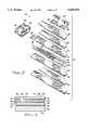
- FIG. 3is an exploded perspective view of the feedthrough assembly of FIG. 1 showing the individual parts thereof in greater detail;
- FIG. 4is a sectional view of a portion of the feedthrough assembly of FIG. 1, showing the manner in which vias are used to couple external contacts to selected portions of the feedthrough assembly;
- FIG. 5is a block diagram of the successive steps in a preferred of making the feedthrough assembly of FIG. 1.
- FIG. 1there is shown a feedthrough assembly 10 in accordance with the present invention for electrically coupling the electronic circuits 12 of an implantable medical device in the form of a cardiac pacemaker 14 to a connector assembly 16 mounted external to the hermetically sealed housing 15.
- the electronic circuits 12are powered by a battery 18, and both the electronic circuits 12 and the battery 18 are contained within the hermetically sealed housing 15 having a housing wall 20.
- Connector blocks 25 and 29are employed to make electrical connection to the pin terminals of an atrial and ventricular implantable leads (not shown), respectively.
- Connector blocks 23 and 27are employed to make electrical connection to the ring terminals of the atrial and ventricular implantable leads (not shown), respectively.
- the feedthrough assembly 10has a first portion 26 thereof residing within the connector assembly 16 and electrically coupled to the connector block 23, 25, 27, 29 located within the receptacles 22 and 24.
- Electrical connection between the feedthrough assembly 10 and the connector blocks 23, 25, 27 and 29may be made with conventional wires or may include a plurality of conductor ribbons formed as a set in a predetermined number, shape and spacing, as taught by commonly assigned U.S. Pat. No. 5,282,841 (Szyszkowski) in which the conductor ribbons would extend between respective ones of the connector blocks 23, 25, 27 and 29 and a respective connector pad at the first portion 26 of the feedthrough assembly 10.
- U.S. Pat. No. 5,282,841is hereby incorporated by reference in its entirety.
- An opposite second portion 28 of the feedthrough assembly 10resides within the pacemaker 14 and is electrically coupled to the electronic circuits 12.
- the feedthrough assembly 10has an intermediate portion 30 thereof between the first and second portions 26 and 28 disposed within and hermetically sealed to a weld ring 32.
- the weld ring 32is mounted in the housing wall 20 of the pacemaker 14 in hermetically sealed fashion.
- the feedthrough assembly 10is shown in greater detail in FIG. 2.
- the feedthrough assembly 10includes the weld ring 32 and an elongated, multilayered structure 34.
- the multilayered structure 34extends through and is hermetically sealed to the interior of the weld ring 32 at the intermediate portion 30.
- the first and second portions 26 and 28reside at opposite sides of the weld ring 32.
- the multilayered structure 34includes a generally planar array of printed conductors extending along the length of the elongated multilayered structure 34 and being comprised of positive traces surrounded by a ground trace.
- the positive tracesterminate in connector pads 36 at the first portion 26.
- Apertures 38 within an electrically insulated ceramic layer 40 of the multilayered structure 34expose the connector pads 36 to facilitate connection thereof to the receptacles 22 and 24 of the connector assembly 16 shown in FIG. 1.
- the second portion 28 of the feedthrough assembly 10has a ceramic layer 42 extending along a top portion thereof and mounting a plurality of contact pads 44 thereon.
- the contact pads 44include a plurality of positive contacts 46 and a plurality of ground contacts 48.
- a plurality of filtering capacitors 50are coupled between the positive contacts 46 and the ground contacts 48.
- the elongated, multilayered structure 34includes the ceramic layers 40 and 42 in addition to ceramic layers 52 and 54. Conductors are printed on the ceramic layer 52 so as to form a generally planar array of printed conductors 56, including positive traces 58 which extend between the first and second portions 26 and 28, and a ground trace 60 surrounding the positive traces 58.
- the positive traces 58terminate in the connector pads 36 at the first portion 26. Opposite ends of the positive traces 58 terminate in connector pads 62 at the second portion 28.
- the array of printed conductors 56is sandwiched between the ceramic layers 40 and 52 which respectively form first and second ceramic layers.
- the first ceramic layer 40has the apertures 38 formed therein for exposing the connector pads 36 at the first portion 26.
- the ceramic layers 42 and 54form third and fourth ceramic layers respectively.
- a first ground plane 64is formed by printing between the first ceramic layer 40 and the third ceramic layer 42. This disposes the first ground plane 64 on the opposite side of the first ceramic layer 40 from the conductor array 56.
- a second ground plane 66is printed between the second ceramic layer 52 and the fourth ceramic layer 54, so as to be disposed on the opposite side of the second ceramic layer 52 from the conductor array 56.
- the ground planes 64 and 66are electrically coupled by vias to the ground trace 60 of the array of printed conductors 56 to electrically ground the planes 64 and 66.
- the ground planes 64 and 66combine with the ground trace 60, the weld ring 32 and the appropriate vias to form a conductive "boot" surrounding the signal paths of the array of printed conductors 56.
- a low resistance pathis presented as an alternative to the torturous path between the ground trace 60 or the ground planes 64 and 66 and the positive traces 58. Because electrical energy tends to take the path of least resistance, noise which reaches the ground planes 64 and 66 or the ground trace 60 follows the lower resistance path to ground, where it is dissipated. In this manner, electrical field shielding is provided.
- the first and second ceramic layers comprised of the layers 40 and 52are disposed on opposite sides of and insulate the array of printed conductors 56, except for vias which extend through the ceramic layers 40 and 52.
- the ceramic layer 40has a plurality of apertures 68 therein through which vias extend to couple the connector pads 62. Such vias extend through the apertures 68, through apertures 70 in the first ground plane 64, and through apertures 72 in the third ceramic layer 42, to the positive contacts 46 mounted on the outside of the third ceramic layer 42.
- the ground contacts 48 on the outside of the third ceramic layer 42are coupled to the first ground plane 64 by vias extending through selected ones of the apertures 72 in the third ceramic layer 42.
- the third ceramic layer 42is disposed against and insulates the first ground plane 64 from the positive contacts 46 and the ground contacts 48.
- the first ground plane 64is grounded by a via which couples the ground plane 64 through an aperture 74 in the first ceramic layer 40 to the ground trace 60.
- the second ground plane 66is grounded by a via which couples the ground plane 66 through an aperture 76 in the second ceramic layer 52 to the ground trace 60.
- the fourth ceramic layer 54is disposed on the opposite side of the second ground plane 66 from the second ceramic layer 52 so as to insulate the second ground plane 66 from the exterior of the feedthrough assembly 10.
- the filtering capacitors 50extend between and are coupled to opposite pairs of the positive contacts 46 and the ground contacts 48. At the same time, the positive contacts 46 are coupled to the electronic circuits 12 of the cardiac pacemaker 14.
- the filtering capacitors 50perform a desired filtering function by presenting a low resistance path to ground for undesirable frequencies. Because electrical energy tends to take the path of least resistance, undesirable frequencies follow the lower resistance path to ground, where they are dissipated, thus limiting the spectrum of frequencies received by the electrical circuits 12.
- FIG. 4shows one of the positive contacts 46 and one of the ground contacts 48 at the top of the third ceramic layer 42.
- the positive contact 46is coupled to a connector pad 62 in the array of printed conductors 56 by a via 78.
- the via 78extends through an aperture 72 in the third ceramic layer 42, through an aperture 70 in the first ground plane 64 and through an aperture 68 in the first ceramic layer 40, to the connector pad 62.
- the ground contact 48is grounded by a via 80 which extends through an aperture 72 in the third ceramic layer 42 to the first ground plane 64.
- first and second ground planes 64 and 66are grounded by vias coupled to the ground trace 60 within the array of printed conductors 56.
- the viassuch as the vias 78 and 80 of FIG. 4, can be provided by any appropriate conventional circuit board interconnection, such as by punching or drilling, followed by conductive ink printing.
- the ceramic layers 42, 40, 52 and 54are made of electrically insulating material.
- such layersare made of alumina, although other insulating materials can be used where desired.
- Conductive portions of the feedthrough assembly 10can be made of any appropriate conductive material which is printable and compatible with the electrically insulating layer material. These include the array of printed conductors 56, with its positive traces 58, its ground trace 60, and the connector pads 36 and 62, the first and second ground planes 64 and 66, the positive contacts 46 and the ground contacts 48.
- such conductive membersare made of platinum alloy.
- the weld ring 32is made of titanium alloy, and is hermetically sealed by brazing the interior thereof with any appropriate material, such as gold alloy, to the multilayered structure 34.
- the hermetically sealed housing 15is, advantageously, made of two half clam shells (not shown) as is known in the art. When the clam shells are mated together, an aperture is formed dimensioned to fit within groove 82.
- the feedthrough assembly 10is attached to the housing wall 20 of the cardiac pacemaker 14 by laser welding around a flange 84 in the direction of the arrow 86 in the exterior of the weld ring 32.
- FIG. 5shows the successive steps in a preferred method of making a feedthrough assembly, such as the feedthrough assembly 10, in accordance with the invention.
- a first step 90the ceramic layers are formed. This includes the first ceramic layer 40, the second ceramic layer 52, the third ceramic layer 42 and the fourth ceramic layer 54.
- a second step 92apertures and vias are created in the appropriate ceramic layers.
- the apertures 72 and associated viasare created in the third ceramic layer 42
- the apertures 68 and 74 and the associated viasare created in the first ceramic layer 40
- the aperture 76 and associated viaare created in the second ceramic layer 52.
- conductive traces, ground planes, contacts and viasare printed on the appropriate ceramic layers.
- Conventional screen printing techniquesare used to accomplish such conductive material deposition.
- a fourth step 96shown in FIG. 5, the ceramic layers are stacked and laminated with printing in an appropriate configuration, to form a ceramic assembly.
- the ceramic layers 42, 40, 52 and 54are stacked and laminated, to form a ceramic assembly.
- the ceramic assemblyis fired into a final state, to form the monolithic hermetic structure. The structure is then shaped to a desired final configuration, in a sixth step 100.
- a seventh step 102shown in FIG. 5, conductive material is applied to a selected surface portion in the region of the intermediate portion 30 of the monolithic hermetic structure. This is in preparation for welding, which takes place in an eighth step 104.
- the weld ring 32is placed over the selected surface portion and is brazed using gold alloy to hermetically seal the weld ring 32 to the outside of the monolithic hermetic structure.
- the filtering capacitors 50are attached to the positive contacts 46 and the ground contacts 48, to complete the feedthrough assembly 10.
Landscapes
- Health & Medical Sciences (AREA)
- Engineering & Computer Science (AREA)
- Biomedical Technology (AREA)
- Nuclear Medicine, Radiotherapy & Molecular Imaging (AREA)
- Radiology & Medical Imaging (AREA)
- Life Sciences & Earth Sciences (AREA)
- Animal Behavior & Ethology (AREA)
- General Health & Medical Sciences (AREA)
- Public Health (AREA)
- Veterinary Medicine (AREA)
- Electrotherapy Devices (AREA)
Abstract
Description
The present invention relates generally to implantable medical devices, such as cardiac pacemakers, cardioverters and defibrillators, and more particularly, to a wireless feedthrough assembly for connecting electronic circuits within an implantable medical device to the connector top and for providing electric field shielding and filtering.
Although it will become evident to those skilled in the art that the present invention is applicable to a variety of implantable medical devices utilizing pulse generators to stimulate selected body tissue, the invention and its background will be described principally in the context of a specific example of such devices, namely, cardiac pacemakers for providing precisely controlled stimulation pulses to the heart via an external connector assembly having lead-receiving receptacles. The appended claims are not intended to be limited, however, to any specific example or embodiment described herein.
Cardiac pacemakers, and other implantable medical devices such as cardiac defibrillators, are hermetically packaged to isolate the device from the body environment. Such devices require that electrical signals be passed between the packaged device and its external connectors, without compromising the hermeticity of the package. Depending on the configuration of the implantable device, there may be multiple electrical paths required between the device and its external connectors. These paths must be electrically and mechanically integrated with the device to provide a safe, long-term arrangement which does not compromise the hermetic package.
Typically, electrical coupling between the electronic circuits of the implantable device and the external connections provided by a connector assembly mounted outside of the implantable device are provided by a feedthrough assembly. The feedthrough assembly extends through the hermetically sealed outer wall of the device and into the connector assembly so as to couple the electronic circuits within the implantable device to lead-receiving receptacles within the connector assembly. Common feedthrough assemblies contain a number of wires equal to the number of electrical paths required for the configuration. The wires are placed in a ceramic sleeve and are sealed and mechanically secured to the sleeve, such as by brazing. The ceramic sleeve is secured to a weld ring, such as by brazing, following which the weld ring is integrated into the housing wall of the implantable device, such as by laser welding. The resulting feedthrough assembly has many individual seals and exposed lengths of wire.
Feedthrough assemblies of the type described have a number of potential problems. One such problem results from the large number of seals required. Because the plurality of wires and the weld ring each require a separate seal, the large number of seals increases the chances of a compromised seal and the resulting loss of hermeticity. Moreover, the exposed wires act as an antenna for environmental noise sources. Such noise compromises the quality of the signal transmitted, and this can lead to misinterpretation by the implantable device. Additionally, the wires can be damaged by misalignment or bending during handling of the feedthrough assembly.
It would therefore be desirable to provide a feedthrough assembly which eliminates the use of wires, reduces the number of seals required so as to reduce the potential for lost hermeticity, and eliminates the possibility of wire misalignment or bending during the handling.
It would furthermore be desirable to provide a feedthrough assembly which incorporates electric field shielding to protect the electrical paths from potential noise sources, and thus potentially inaccurate signals.
It would still furthermore be desirable to provide a feedthrough assembly which integrates signal filtering within the assembly itself, so as to focus the spectrum of frequencies to be interpreted by the implantable device.
Briefly stated, the present invention provides a feedthrough assembly in which plural wires are eliminated in favor of a single, monolithic structure of elongated configuration which extends through and is hermetically sealed to a sealing device such as a weld ring. The weld ring is, in turn, hermetically sealed within the housing wall of the implantable device. The monolithic structure comprises a multilayered structure in which an array of printed conductors provides the connections between the electronic circuits of the implantable device and the lead-receiving receptacles of the connector assembly. Electric field shielding of the printed conductors is provided by a conductive boot surrounding the printed conductors and being coupled to ground. The conductive boot may be provided by printed ground planes on opposite sides of the printed conductors within a multilayered structure. Filtering is provided by capacitors coupled between positive contacts and ground contacts within a second portion of the feedthrough assembly residing within the implantable device.
In accordance with a specific, exemplary embodiment of the present invention, the feedthrough assembly includes an elongated, multilayered structure having an intermediate portion thereof hermetically sealed to the inside of a weld ring between opposite first and second portions residing within the connector assembly and the interior of the implantable device, respectively. The multilayered structure includes a generally planar array of printed conductors extending between the opposite first and second portions, and comprised of positive traces surrounded by a ground trace. The positive traces terminate at connector pads within the first portion, which connector pads are coupled to the lead-receiving receptacles of the connector assembly. Opposite ends of the positive traces within the second portion terminate in connector pads which are coupled by vias to contact pads at the exterior of the second portion. Such contact pads are coupled to the electronic circuits of the implantable device.
The multilayered structure comprises a laminate of electrically insulating ceramic layers, with first and second ones of the ceramic layers being disposed on opposite sides of and insulating the printed conductors from opposite first and second printed ground planes. The first and second ground planes are coupled by vias extending through the first and second ceramic layers to the ground trace, to form a grounded conductive envelope surrounding the printed conductors. The grounded envelope shields the printed conductors from electric fields.
The laminate of ceramic layers includes third and fourth layers of ceramic disposed on opposite sides of the first and second ground planes from the first and second ceramic layers, respectively. The third ceramic layer mounts the contact pads at the exterior of the second portion. The contact pads include positive contacts coupled to the positive traces of the printed conductors by vias extending through apertures in the third ceramic layer, the first ground plane and the first ceramic layer. The contact pads also include ground contacts coupled to the first ground plane by vias extending through apertures in the third ceramic layer. The positive contacts are coupled to the electronic circuits of the implantable device. At the same time, discrete filtering capacitors coupled between the positive and ground contacts on the third ceramic layer provide filtering to limit the spectrum of frequencies receivable by the electronic circuits.
In a preferred method of making a feedthrough assembly in accordance with the present invention, a plurality of ceramic layers are first formed, following which apertures and vias are created in appropriate ones of the layers. Next, vias are filled and conductive traces, ground planes and contacts are printed on the appropriate ceramic layers. The ceramic layers are then stacked and laminated with printing in an appropriate configuration to form a ceramic assembly. The ceramic assembly is fired to form a monolithic hermetic structure. The structure is then shaped to a desired final configuration. Conductive material is applied to a selected surface portion of the structure, at the intermediate portion thereof, before placing a weld ring over the selected surface portion and brazing to form a hermetic seal between the structure and the weld ring. Filtering capacitors are then attached to the contacts at the exterior of the second portion, to complete the feedthrough assembly.
Further objects, advantages and features of the invention will become apparent from the detailed description of the preferred embodiment when read in conjunction with the accompanying drawings, in which:
FIG. 1 is a sectional view of a cardiac pacemaker and an external connector assembly in which a feedthrough assembly according to the invention provides electrical coupling therebetween;
FIG. 2 is a perspective view of the feedthrough assembly of FIG. 1;
FIG. 3 is an exploded perspective view of the feedthrough assembly of FIG. 1 showing the individual parts thereof in greater detail;
FIG. 4 is a sectional view of a portion of the feedthrough assembly of FIG. 1, showing the manner in which vias are used to couple external contacts to selected portions of the feedthrough assembly; and
FIG. 5 is a block diagram of the successive steps in a preferred of making the feedthrough assembly of FIG. 1.
In FIG. 1, there is shown afeedthrough assembly 10 in accordance with the present invention for electrically coupling theelectronic circuits 12 of an implantable medical device in the form of acardiac pacemaker 14 to aconnector assembly 16 mounted external to the hermetically sealedhousing 15. Theelectronic circuits 12 are powered by abattery 18, and both theelectronic circuits 12 and thebattery 18 are contained within the hermetically sealedhousing 15 having ahousing wall 20. Theconnector assembly 16, which is mounted at the outside of thewall 20 of thepacemaker 14, includes a plurality ofreceptacles Connector blocks Connector blocks 23 and 27 are employed to make electrical connection to the ring terminals of the atrial and ventricular implantable leads (not shown), respectively.
Thefeedthrough assembly 10 has afirst portion 26 thereof residing within theconnector assembly 16 and electrically coupled to theconnector block receptacles
Electrical connection between thefeedthrough assembly 10 and the connector blocks 23, 25, 27 and 29 may be made with conventional wires or may include a plurality of conductor ribbons formed as a set in a predetermined number, shape and spacing, as taught by commonly assigned U.S. Pat. No. 5,282,841 (Szyszkowski) in which the conductor ribbons would extend between respective ones of the connector blocks 23, 25, 27 and 29 and a respective connector pad at thefirst portion 26 of thefeedthrough assembly 10. U.S. Pat. No. 5,282,841 is hereby incorporated by reference in its entirety.
An oppositesecond portion 28 of thefeedthrough assembly 10 resides within thepacemaker 14 and is electrically coupled to theelectronic circuits 12. As described in detail hereafter, thefeedthrough assembly 10 has anintermediate portion 30 thereof between the first andsecond portions weld ring 32. Theweld ring 32 is mounted in thehousing wall 20 of thepacemaker 14 in hermetically sealed fashion.
Thefeedthrough assembly 10 is shown in greater detail in FIG. 2. As shown therein, thefeedthrough assembly 10 includes theweld ring 32 and an elongated,multilayered structure 34. Themultilayered structure 34 extends through and is hermetically sealed to the interior of theweld ring 32 at theintermediate portion 30. The first andsecond portions weld ring 32. As described in detail hereafter, themultilayered structure 34 includes a generally planar array of printed conductors extending along the length of the elongatedmultilayered structure 34 and being comprised of positive traces surrounded by a ground trace. The positive traces terminate inconnector pads 36 at thefirst portion 26.Apertures 38 within an electrically insulatedceramic layer 40 of themultilayered structure 34 expose theconnector pads 36 to facilitate connection thereof to thereceptacles connector assembly 16 shown in FIG. 1.
Thesecond portion 28 of thefeedthrough assembly 10 has aceramic layer 42 extending along a top portion thereof and mounting a plurality ofcontact pads 44 thereon. Thecontact pads 44 include a plurality ofpositive contacts 46 and a plurality ofground contacts 48. A plurality offiltering capacitors 50 are coupled between thepositive contacts 46 and theground contacts 48.
The details of thefeedthrough assembly 10 may be better understood with reference to the exploded perspective view of FIG. 3. As shown therein, the elongated,multilayered structure 34 includes theceramic layers ceramic layers ceramic layer 52 so as to form a generally planar array of printedconductors 56, includingpositive traces 58 which extend between the first andsecond portions ground trace 60 surrounding the positive traces 58. The positive traces 58 terminate in theconnector pads 36 at thefirst portion 26. Opposite ends of thepositive traces 58 terminate inconnector pads 62 at thesecond portion 28.
By printing the array of printedconductors 56 on theceramic layer 52, the array of printedconductors 56 is sandwiched between theceramic layers ceramic layer 40 has theapertures 38 formed therein for exposing theconnector pads 36 at thefirst portion 26.
As shown in FIG. 3, theceramic layers first ground plane 64 is formed by printing between the firstceramic layer 40 and the thirdceramic layer 42. This disposes thefirst ground plane 64 on the opposite side of the firstceramic layer 40 from theconductor array 56. Asecond ground plane 66 is printed between the secondceramic layer 52 and the fourthceramic layer 54, so as to be disposed on the opposite side of the secondceramic layer 52 from theconductor array 56.
As described in greater detail in FIG. 4, the ground planes 64 and 66 are electrically coupled by vias to theground trace 60 of the array of printedconductors 56 to electrically ground theplanes ground trace 60, theweld ring 32 and the appropriate vias to form a conductive "boot" surrounding the signal paths of the array of printedconductors 56. By coupling the "boot" to ground, a low resistance path is presented as an alternative to the torturous path between theground trace 60 or the ground planes 64 and 66 and the positive traces 58. Because electrical energy tends to take the path of least resistance, noise which reaches the ground planes 64 and 66 or theground trace 60 follows the lower resistance path to ground, where it is dissipated. In this manner, electrical field shielding is provided.
As seen in FIG. 3, the first and second ceramic layers comprised of thelayers conductors 56, except for vias which extend through theceramic layers ceramic layer 40 has a plurality ofapertures 68 therein through which vias extend to couple theconnector pads 62. Such vias extend through theapertures 68, throughapertures 70 in thefirst ground plane 64, and throughapertures 72 in the thirdceramic layer 42, to thepositive contacts 46 mounted on the outside of the thirdceramic layer 42. Theground contacts 48 on the outside of the thirdceramic layer 42 are coupled to thefirst ground plane 64 by vias extending through selected ones of theapertures 72 in the thirdceramic layer 42. At the same time, the thirdceramic layer 42 is disposed against and insulates thefirst ground plane 64 from thepositive contacts 46 and theground contacts 48.
Thefirst ground plane 64 is grounded by a via which couples theground plane 64 through anaperture 74 in the firstceramic layer 40 to theground trace 60. Thesecond ground plane 66 is grounded by a via which couples theground plane 66 through anaperture 76 in the secondceramic layer 52 to theground trace 60. The fourthceramic layer 54 is disposed on the opposite side of thesecond ground plane 66 from the secondceramic layer 52 so as to insulate thesecond ground plane 66 from the exterior of thefeedthrough assembly 10.
Thefiltering capacitors 50 extend between and are coupled to opposite pairs of thepositive contacts 46 and theground contacts 48. At the same time, thepositive contacts 46 are coupled to theelectronic circuits 12 of thecardiac pacemaker 14. Thefiltering capacitors 50 perform a desired filtering function by presenting a low resistance path to ground for undesirable frequencies. Because electrical energy tends to take the path of least resistance, undesirable frequencies follow the lower resistance path to ground, where they are dissipated, thus limiting the spectrum of frequencies received by theelectrical circuits 12.
The sectional view of FIG. 4 illustrates the manner in which vias are used to electrically couple the various components shown in FIG. 3. FIG. 4 shows one of thepositive contacts 46 and one of theground contacts 48 at the top of the thirdceramic layer 42. Thepositive contact 46 is coupled to aconnector pad 62 in the array of printedconductors 56 by a via 78. The via 78 extends through anaperture 72 in the thirdceramic layer 42, through anaperture 70 in thefirst ground plane 64 and through anaperture 68 in the firstceramic layer 40, to theconnector pad 62. Theground contact 48 is grounded by a via 80 which extends through anaperture 72 in the thirdceramic layer 42 to thefirst ground plane 64. In similar fashion, the first and second ground planes 64 and 66 are grounded by vias coupled to theground trace 60 within the array of printedconductors 56. The vias, such as thevias
As previously described, theceramic layers feedthrough assembly 10 can be made of any appropriate conductive material which is printable and compatible with the electrically insulating layer material. These include the array of printedconductors 56, with itspositive traces 58, itsground trace 60, and theconnector pads positive contacts 46 and theground contacts 48. In the present example, such conductive members are made of platinum alloy. Theweld ring 32 is made of titanium alloy, and is hermetically sealed by brazing the interior thereof with any appropriate material, such as gold alloy, to themultilayered structure 34.
The hermetically sealedhousing 15 is, advantageously, made of two half clam shells (not shown) as is known in the art. When the clam shells are mated together, an aperture is formed dimensioned to fit withingroove 82. Thefeedthrough assembly 10 is attached to thehousing wall 20 of thecardiac pacemaker 14 by laser welding around aflange 84 in the direction of thearrow 86 in the exterior of theweld ring 32.
FIG. 5 shows the successive steps in a preferred method of making a feedthrough assembly, such as thefeedthrough assembly 10, in accordance with the invention. In afirst step 90, the ceramic layers are formed. This includes the firstceramic layer 40, the secondceramic layer 52, the thirdceramic layer 42 and the fourthceramic layer 54. In asecond step 92, apertures and vias are created in the appropriate ceramic layers. Thus, theapertures 72 and associated vias are created in the thirdceramic layer 42, theapertures ceramic layer 40, and theaperture 76 and associated via are created in the secondceramic layer 52. In athird step 94, conductive traces, ground planes, contacts and vias are printed on the appropriate ceramic layers. This includes printing of thepositive contacts 46 and theground contacts 48 on the upper surface of the thirdceramic layer 42, thefirst ground plane 64 on the upper surface of the firstceramic layer 40, the array of printedconductors 56 on the upper surface of the secondceramic layer 52, and thesecond ground plane 66 on the upper surface of the fourthceramic layer 54. Conventional screen printing techniques are used to accomplish such conductive material deposition.
In afourth step 96, shown in FIG. 5, the ceramic layers are stacked and laminated with printing in an appropriate configuration, to form a ceramic assembly. Thus, theceramic layers fifth step 98, the ceramic assembly is fired into a final state, to form the monolithic hermetic structure. The structure is then shaped to a desired final configuration, in a sixth step 100.
In aseventh step 102, shown in FIG. 5, conductive material is applied to a selected surface portion in the region of theintermediate portion 30 of the monolithic hermetic structure. This is in preparation for welding, which takes place in aneighth step 104. In thestep 104, theweld ring 32 is placed over the selected surface portion and is brazed using gold alloy to hermetically seal theweld ring 32 to the outside of the monolithic hermetic structure. In a finalninth step 106, thefiltering capacitors 50 are attached to thepositive contacts 46 and theground contacts 48, to complete thefeedthrough assembly 10.
While the invention has been described in connection with a preferred embodiment, it will be understood that it is not intended to limit the invention thereto, but that it is intended to cover all modifications and alternative constructions falling within the spirit and scope of the invention as expressed in the appended claims.
Claims (19)
1. In an implantable medical device having a hermetically sealed housing, said housing including a wall and enclosing electronic circuits for producing electrical stimulating pulses, an improved system for electrically connecting the electronic circuits with an implantable lead, the improved system comprising:
a plurality of connector blocks for making electrical contact with the implantable lead;
a hollow weld ring mounted in the wall of the hermetically sealed housing;
a multilayered structure disposed within and extending from opposite sides of the hollow weld ring so as to have a first portion outside the hermetically sealed housing and an opposite second portion within the hermetically sealed housing, the multilayered structure including a laminate of insulating layers with printed conductors therebetween, the printed conductors extending between the first and second portions and terminating in a first plurality of connector pads at the first portion for connection to respective ones of the plurality of connector blocks and in a second plurality of connector pads at the second portion for connection to the electronic circuits;
conductive means for electrically connecting the plurality of connector blocks with respective ones of the first plurality of connector pads at the first portion of the multilayered structure; and
a connector assembly attached to the hermetically sealed housing enclosing the plurality of connector blocks, the first portion of the multilayer structure and the conductive means therein, the connector assembly further having at least one receptacle for receiving the implantable lead therein.
2. The improved system, as defined in claim 1, wherein:
the printed conductors are disposed in a generally planar array and include positive traces terminating, at opposite ends thereof, in the first plurality of connector pads at the first portion and in the second plurality of connector pads at the second portion; and
the second plurality of connector pads at the second portion are coupled by vias to a plurality of contact pads at an exterior of the second portion, the plurality of contact pads being coupled to the electronic circuits.
3. The improved system, as defined in claim 2, wherein:
the printed conductors include a ground trace disposed outside of the positive traces within the generally planar array; and
the laminate of insulating layers includes first and second ground planes disposed on opposite sides of the generally planar array of printed conductors and electrically coupled to the ground trace to provide magnetic field shielding of the feedthrough assembly.
4. The improved system, as defined in claim 3, wherein:
the laminate of insulating layers includes first and second ceramic layers respectively disposed between the first and second ground planes and the generally planar array of printed conductors.
5. The improved system, as defined in claim 4, wherein:
the first ceramic layer has a plurality of apertures therein in an end portion thereof providing access to the first plurality of connector pads at the first portion of the multilayered structure.
6. The improved system, as defined in claim 4, wherein:
the laminate of insulating layers includes a third ceramic layer disposed on the opposite side of the first ground plane from the first ceramic layer and mounting the plurality of contact pads at the exterior of the second portion; and
the plurality of contact pads includes a plurality of positive contacts coupled by vias extending through apertures in the third ceramic layer, the first ground plane and the first ceramic layer to the positive traces of the generally planar array of printed conductors.
7. The improved system, as defined in claim 6, further comprising:
a plurality of ground contacts mounted on the third ceramic layer and coupled by vias extending through the third ceramic layer to the first ground plane; and
a plurality of filtering capacitors coupled between the positive contacts and the ground contacts.
8. The improved system, as defined in claim 2, wherein:
the printed conductors include positive traces and a ground trace;
the plurality of contact pads at the exterior of the second portion include positive contacts coupled to the positive traces of the printed conductors and ground contacts coupled to the ground trace of the printed conductors; and
further including a plurality of filtering capacitors coupled between the positive contacts and the ground contacts.
9. In an implantable medical device having a hermetically sealed housing, said housing including a wall and enclosing electronic circuits for producing electrical stimulating pulses, an improved system for electrically connecting the electronic circuits with an implantable lead, the improved system comprising:
at least one connector block for making electrical contact with the implantable lead;
an elongated multilayered structure having a first portion for disposition outside the hermetically sealed housing, an opposite second portion for disposition inside the hermetically sealed housing and an intermediate portion between the first and second portions adapted to be disposed, in hermetically sealed fashion, within the wall of the hermetically sealed housing, the multilayered structure including a generally planar array of printed conductors disposed between opposite layers of electrically insulating material and extending between the first and second portions, at least one connector pad coupled to the generally planar array of printed conductors at the first portion for coupling to the at least one connector block, and at least one contact coupled to the generally planar array of printed conductors at the second portion for coupling to the electronic circuits of the implantable medical device;
conductive means for electrically connecting the at least one connector block and the at least one connector pad at the first portion of the multilayered structure; and
a connector assembly attached to the hermetically sealed housing enclosing the at least one connector block, the first portion of the multilayer structure and the conductive means therein.
10. The improved system, as defined in claim 9, further comprising:
means disposed around the generally planar array of printed conductors for electrically shielding such printed conductors.
11. The improved system, as defined in claim 10, wherein the means for electrically shielding comprises:
a conductive envelope surrounding the generally planar array of printed conductors and electrically coupled to ground.
12. The improved system, as defined in claim 11, wherein:
the generally planar array of printed conductors includes positive traces and a ground trace disposed outside of the positive traces; and
the conductive envelope includes first and second ground planes disposed on opposite sides of the generally planar array of printed conductors and electrically coupled to the ground trace.
13. The improved system, as defined in claim 12, further comprising:
first and second ceramic layers disposed on opposite sides of the generally planar array of printed conductors between the generally planar array of printed conductors and the first and second ground planes respectively;
a third ceramic layer disposed opposite the first ground plane from the first ceramic layer; and
a fourth ceramic layer disposed opposite the second ground plane from the second ceramic layer.
14. The improved system, as defined in claim 13, wherein:
the first and second ground planes are coupled to the ground trace by vias extending through the first and second ceramic layers respectively; and
the at least one contact is mounted on the third ceramic layer and is coupled to the positive traces by at least one via extending through the third ceramic layer, the first ground plane, and the first ceramic layer.
15. The improved system, as defined in claim 13, wherein:
the generally planar array of printed conductors, the at least one connector pad, the at least one contact and the first and second ground planes are made of platinum alloy; and
the first, second, third and fourth ceramic layers are made of alumina.
16. The improved system, as defined in claim 9, further comprising:
filtering means coupled to the at least one contact for limiting a spectrum of frequencies receivable by the improved system.
17. The improved system, as defined in claim 16, wherein:
the at least one contact includes a plurality of positive contacts coupled to the generally planar array of printed conductors and a plurality of electrically grounded ground contacts; and
the filtering means includes a plurality of filtering capacitors coupled between the positive contacts and the ground contacts.
18. The improved system, as defined in claim 9, further comprising:
a weld ring disposed around and sealed to the intermediate portion of the elongated, multilayered structure, the weld ring being hermetically sealed within the housing.
19. The improved system, as defined in claim 18, wherein the weld ring is made of titanium alloy and is hermetically sealed within the housing by laser welding.
Priority Applications (2)
| Application Number | Priority Date | Filing Date | Title |
|---|---|---|---|
| US08/565,204US5620476A (en) | 1995-11-13 | 1995-11-13 | Implantable medical device having shielded and filtered feedthrough assembly and methods for making such assembly |
| US08/748,307US5683435A (en) | 1995-11-13 | 1996-11-13 | Implantable medical device having shielded and filtered feedthrough assembly and methods for making such assembly |
Applications Claiming Priority (1)
| Application Number | Priority Date | Filing Date | Title |
|---|---|---|---|
| US08/565,204US5620476A (en) | 1995-11-13 | 1995-11-13 | Implantable medical device having shielded and filtered feedthrough assembly and methods for making such assembly |
Related Child Applications (1)
| Application Number | Title | Priority Date | Filing Date |
|---|---|---|---|
| US08/748,307DivisionUS5683435A (en) | 1995-11-13 | 1996-11-13 | Implantable medical device having shielded and filtered feedthrough assembly and methods for making such assembly |
Publications (1)
| Publication Number | Publication Date |
|---|---|
| US5620476Atrue US5620476A (en) | 1997-04-15 |
Family
ID=24257628
Family Applications (2)
| Application Number | Title | Priority Date | Filing Date |
|---|---|---|---|
| US08/565,204Expired - LifetimeUS5620476A (en) | 1995-11-13 | 1995-11-13 | Implantable medical device having shielded and filtered feedthrough assembly and methods for making such assembly |
| US08/748,307Expired - LifetimeUS5683435A (en) | 1995-11-13 | 1996-11-13 | Implantable medical device having shielded and filtered feedthrough assembly and methods for making such assembly |
Family Applications After (1)
| Application Number | Title | Priority Date | Filing Date |
|---|---|---|---|
| US08/748,307Expired - LifetimeUS5683435A (en) | 1995-11-13 | 1996-11-13 | Implantable medical device having shielded and filtered feedthrough assembly and methods for making such assembly |
Country Status (1)
| Country | Link |
|---|---|
| US (2) | US5620476A (en) |
Cited By (112)
| Publication number | Priority date | Publication date | Assignee | Title |
|---|---|---|---|---|
| US5759197A (en)* | 1994-10-04 | 1998-06-02 | Medtronic, Inc. | Protective feedthrough |
| US5817130A (en)* | 1996-05-03 | 1998-10-06 | Sulzer Intermedics Inc. | Implantable cardiac cardioverter/defibrillator with EMI suppression filter with independent ground connection |
| US5867361A (en)* | 1997-05-06 | 1999-02-02 | Medtronic Inc. | Adhesively-bonded capacitive filter feedthrough for implantable medical device |
| US5895980A (en)* | 1996-12-30 | 1999-04-20 | Medical Pacing Concepts, Ltd. | Shielded pacemaker enclosure |
| US5959829A (en)* | 1998-02-18 | 1999-09-28 | Maxwell Energy Products, Inc. | Chip capacitor electromagnetic interference filter |
| US5973906A (en)* | 1998-03-17 | 1999-10-26 | Maxwell Energy Products, Inc. | Chip capacitors and chip capacitor electromagnetic interference filters |
| US5987358A (en)* | 1998-02-17 | 1999-11-16 | Intermedics, Inc. | Semiconductor device packaging and method of fabrication |
| US6037846A (en)* | 1998-10-09 | 2000-03-14 | Nortel Networks Corporation | Surface mount EMI gasket filter |
| US6088894A (en)* | 1997-02-11 | 2000-07-18 | Tetrad Corporation | Methods of making composite ultrasonic transducers |
| US6349025B1 (en) | 1999-11-30 | 2002-02-19 | Medtronic, Inc. | Leak testable capacitive filtered feedthrough for an implantable medical device |
| WO2002037511A1 (en)* | 2000-11-03 | 2002-05-10 | Saint-Gobain Ceramiques Avancees Desmarquest | Method for making a sealed feedthrough with integrated capacitor and resulting element |
| US6414835B1 (en) | 2000-03-01 | 2002-07-02 | Medtronic, Inc. | Capacitive filtered feedthrough array for an implantable medical device |
| US6459935B1 (en) | 2000-07-13 | 2002-10-01 | Avx Corporation | Integrated filter feed-thru |
| US6473291B1 (en) | 1999-03-16 | 2002-10-29 | Gb Aquisition Co., Inc. | Low inductance four terminal capacitor lead frame |
| US20030191505A1 (en)* | 2002-04-09 | 2003-10-09 | Mark Gryzwa | Magnetic structure for feedthrough filter assembly |
| US20040020657A1 (en)* | 2002-07-31 | 2004-02-05 | Patel Dinesh R. | Multiple interventionless actuated downhole valve and method |
| US20040058186A1 (en)* | 2002-06-28 | 2004-03-25 | Jay Daulton | Self-centering braze assembly |
| US6792312B2 (en) | 2001-09-06 | 2004-09-14 | Medtronic, Inc. | Connector module having internal weld plates |
| US20050033370A1 (en)* | 2003-06-06 | 2005-02-10 | Jeff Jelen | Implantable medical device including a hermetic connector block extension |
| US20050075683A1 (en)* | 2003-10-03 | 2005-04-07 | Miesel Keith Alan | System, apparatus and method for interacting with a targeted tissue of a patient |
| US20050137670A1 (en)* | 2003-12-19 | 2005-06-23 | Christopherson Mark A. | Electrical lead body including an in-line hermetic electronic package and implantable medical device using the same |
| US20050148980A1 (en)* | 2003-12-30 | 2005-07-07 | Kimberly-Clark Worldwide, Inc. | Absorbent garment having outer shell and discreet absorbent assembly adapted for positioning therein |
| US20050197677A1 (en)* | 2004-02-12 | 2005-09-08 | Stevenson Robert A. | Apparatus and process for reducing the susceptability of active implantable medical devices to medical procedures such as magnetic resonance imaging |
| US20060056133A1 (en)* | 2004-09-10 | 2006-03-16 | Bauer Stacey G | Sign ballast capacitor assembly |
| US20060100506A1 (en)* | 1998-11-04 | 2006-05-11 | Johns Hopkins University School Of Medicine | System and method for magnetic-resonance-guided electrophysiologic and ablation procedures |
| US20070060969A1 (en)* | 2005-09-15 | 2007-03-15 | Burdon Jeremy W | Implantable co-fired electrical feedthroughs |
| US20070088416A1 (en)* | 2001-04-13 | 2007-04-19 | Surgi-Vision, Inc. | Mri compatible medical leads |
| US20070167989A1 (en)* | 2006-01-13 | 2007-07-19 | Sleeper Scott B | Feed-through assembly |
| US20070179554A1 (en)* | 2006-01-30 | 2007-08-02 | Lyer Rajesh V | Method and apparatus for minimizing EMI coupling in a feedthrough array having at least one unfiltered feedthrough |
| US20070179551A1 (en)* | 2006-01-30 | 2007-08-02 | Iyer Rajesh V | Filtered electrical interconnect assembly |
| US7260434B1 (en) | 2004-09-23 | 2007-08-21 | Pacesetter, Inc. | Integrated 8-pole filtered feedthrough with backfill tube for implantable medical devices |
| US20070203530A1 (en)* | 2006-02-28 | 2007-08-30 | Hubing Roger L | Filtered multipolar feedthrough assembly |
| US20070236861A1 (en)* | 2006-04-05 | 2007-10-11 | Burdon Jeremy W | Implantable co-fired electrical feedthroughs |
| US20080119906A1 (en)* | 2006-11-17 | 2008-05-22 | Marcel Starke | Filter feedthrough for implants |
| US7391601B1 (en) | 2006-07-12 | 2008-06-24 | Pacesetter, Inc. | Feedthrough filter assembly |
| US20080269591A1 (en)* | 2006-06-08 | 2008-10-30 | Greatbatch Ltd. | Band stop filter employing a capacitor and an inductor tank circuit to enhance mri compatibility of active medical devices |
| US7489968B1 (en) | 2006-04-07 | 2009-02-10 | Pacesetter, Inc. | Pre-molded header with universal tip-to-tip feedthru adaptor |
| US7498516B1 (en) | 2006-06-14 | 2009-03-03 | Boston Scientific Neuromodulation Corporation | Feedthru assembly |
| US20090138058A1 (en)* | 2004-12-17 | 2009-05-28 | Cardiac Pacemakers, Inc. | Mri operation modes for implantable medical devices |
| US7561915B1 (en) | 2004-12-17 | 2009-07-14 | Cardiac Pacemakers, Inc. | MRI system having implantable device safety features |
| US20090187229A1 (en)* | 2007-04-11 | 2009-07-23 | Pacesetter, Inc. | Capacitor-integrated feedthrough assembly with improved grounding for an implantable medical device |
| US20090270956A1 (en)* | 2008-04-25 | 2009-10-29 | Pacesetter, Inc. | Implantable medical lead configured for improved mri safety |
| US20090281592A1 (en)* | 2008-05-08 | 2009-11-12 | Pacesetter, Inc. | Shaft-mounted rf filtering elements for implantable medical device lead to reduce lead heating during mri |
| US20100087892A1 (en)* | 2008-10-02 | 2010-04-08 | Stubbs Scott R | Implantable medical device responsive to mri induced capture threshold changes |
| US20100109958A1 (en)* | 2008-10-31 | 2010-05-06 | Haubrich Gregory J | High Dielectric Substrate Antenna For Implantable Miniaturized Wireless Communications and Method for Forming the Same |
| US20100114245A1 (en)* | 2008-10-31 | 2010-05-06 | Yamamoto Joyce K | Antenna for Implantable Medical Devices Formed on Extension of RF Circuit Substrate and Method for Forming the Same |
| US20100114246A1 (en)* | 2008-10-31 | 2010-05-06 | Yamamoto Joyce K | Co-Fired Multi-Layer Antenna for Implantable Medical Devices and Method for Forming the Same |
| US7719854B2 (en) | 2003-07-31 | 2010-05-18 | Cardiac Pacemakers, Inc. | Integrated electromagnetic interference filters and feedthroughs |
| US20100168818A1 (en)* | 2008-12-31 | 2010-07-01 | Michael William Barror | External RF Telemetry Module for Implantable Medical Devices |
| US20100168817A1 (en)* | 2008-12-29 | 2010-07-01 | Yamamoto Joyce K | Phased Array Cofire Antenna Structure and Method for Forming the Same |
| US20100185263A1 (en)* | 2008-03-20 | 2010-07-22 | Greatbatch Ltd. | Rf activated aimd telemetry transceiver |
| US7771838B1 (en) | 2004-10-12 | 2010-08-10 | Boston Scientific Neuromodulation Corporation | Hermetically bonding ceramic and titanium with a Ti-Pd braze interface |
| US20100211123A1 (en)* | 2009-02-19 | 2010-08-19 | Stubbs Scott R | Systems and methods for providing arrhythmia therapy in mri environments |
| US20100217262A1 (en)* | 2001-04-13 | 2010-08-26 | Greatbatch Ltd. | Frequency selective passive component networks for active implantable medical devices utilizing an energy dissipating surface |
| US20100241206A1 (en)* | 2009-03-19 | 2010-09-23 | Greatbatch Ltd. | Emi shielded conduit assembly for an active implantable medical device |
| US20100256693A1 (en)* | 2009-04-07 | 2010-10-07 | Boston Scientific Neuromodulation Corporation | Insulator layers for leads of implantable electric stimulation systems and methods of making and using |
| US20110004283A1 (en)* | 2008-03-20 | 2011-01-06 | Greatbatch Ltd. | Shielded three-terminal flat-through emi/energy dissipating filter |
| US20110009917A1 (en)* | 2007-04-11 | 2011-01-13 | Pacesetter, Inc. | Capacitor-integrated feedthrough assembly with improved grounding for an implantable medical device |
| US20110029036A1 (en)* | 2009-07-31 | 2011-02-03 | Yamamoto Joyce K | Co-Fired Electrical Feedthroughs for Implantable Medical Devices Having a Shielded RF Conductive Path and Impedance Matching |
| US20110048770A1 (en)* | 2009-08-31 | 2011-03-03 | Medtronic Inc. | Injection molded ferrule for cofired feedthroughs |
| US20110102967A1 (en)* | 2009-10-29 | 2011-05-05 | Medtronic, Inc. | Implantable co-fired electrical feedthroughs |
| EP2329860A1 (en)* | 2009-12-03 | 2011-06-08 | Biotronik CRM Patent AG | Connection housing and manufacture of same |
| US20110137359A1 (en)* | 2009-12-08 | 2011-06-09 | Stubbs Scott R | Implantable medical device with automatic tachycardia detection and control in mri environments |
| US8032228B2 (en) | 2007-12-06 | 2011-10-04 | Cardiac Pacemakers, Inc. | Method and apparatus for disconnecting the tip electrode during MRI |
| USRE42856E1 (en) | 2002-05-29 | 2011-10-18 | MRI Interventions, Inc. | Magnetic resonance probes |
| US20110257711A1 (en)* | 2010-03-31 | 2011-10-20 | Medtronic, Inc. | Medical Devices Including Flexible Circuit Bodies with Exposed Portions of Circuit Traces Attached to Electrical Contacts of Components |
| US8086321B2 (en) | 2007-12-06 | 2011-12-27 | Cardiac Pacemakers, Inc. | Selectively connecting the tip electrode during therapy for MRI shielding |
| US20120016444A1 (en)* | 2010-07-15 | 2012-01-19 | Advanced Bionics Llc | Implantable Hermetic Feedthrough |
| US8160717B2 (en) | 2008-02-19 | 2012-04-17 | Cardiac Pacemakers, Inc. | Model reference identification and cancellation of magnetically-induced voltages in a gradient magnetic field |
| US20120149254A1 (en)* | 2007-10-02 | 2012-06-14 | Medtronic, Inc | Connector assemblies and contacts for implantable medical electrical systems |
| US8311637B2 (en) | 2008-02-11 | 2012-11-13 | Cardiac Pacemakers, Inc. | Magnetic core flux canceling of ferrites in MRI |
| US8329314B1 (en) | 2004-10-12 | 2012-12-11 | Boston Scientific Neuromodulation Corporation | Hermetically bonding ceramic and titanium with a palladium braze |
| US8552311B2 (en) | 2010-07-15 | 2013-10-08 | Advanced Bionics | Electrical feedthrough assembly |
| US8588916B2 (en) | 2011-08-02 | 2013-11-19 | Medtronic, Inc. | Feedthrough configured for interconnect |
| US8644002B2 (en) | 2011-05-31 | 2014-02-04 | Medtronic, Inc. | Capacitor including registration feature for aligning an insulator layer |
| US8644936B2 (en) | 2012-01-09 | 2014-02-04 | Medtronic, Inc. | Feedthrough assembly including electrical ground through feedthrough substrate |
| US8653384B2 (en) | 2012-01-16 | 2014-02-18 | Greatbatch Ltd. | Co-fired hermetically sealed feedthrough with alumina substrate and platinum filled via for an active implantable medical device |
| US8670829B2 (en) | 2011-08-02 | 2014-03-11 | Medtronic, Inc. | Insulator for a feedthrough |
| US8841558B2 (en) | 2011-08-02 | 2014-09-23 | Medtronic Inc. | Hermetic feedthrough |
| US8844103B2 (en) | 2011-09-01 | 2014-09-30 | Medtronic, Inc. | Methods for making feedthrough assemblies including a capacitive filter array |
| US8872035B2 (en) | 2011-08-02 | 2014-10-28 | Medtronic, Inc. | Hermetic feedthrough |
| US9008779B2 (en) | 2011-08-02 | 2015-04-14 | Medtronic, Inc. | Insulator for a feedthrough |
| US9093974B2 (en) | 2012-09-05 | 2015-07-28 | Avx Corporation | Electromagnetic interference filter for implanted electronics |
| US9101782B2 (en) | 2011-08-19 | 2015-08-11 | Greatbatch Ltd. | Implantable cardioverter defibrillator designed for use in a magnetic resonance imaging environment |
| US9108066B2 (en) | 2008-03-20 | 2015-08-18 | Greatbatch Ltd. | Low impedance oxide resistant grounded capacitor for an AIMD |
| US9248283B2 (en) | 2001-04-13 | 2016-02-02 | Greatbatch Ltd. | Band stop filter comprising an inductive component disposed in a lead wire in series with an electrode |
| US9295828B2 (en) | 2001-04-13 | 2016-03-29 | Greatbatch Ltd. | Self-resonant inductor wound portion of an implantable lead for enhanced MRI compatibility of active implantable medical devices |
| US9403022B2 (en) | 2010-01-29 | 2016-08-02 | Medtronic, Inc. | Header assembly for implantable medical device |
| US9427596B2 (en) | 2013-01-16 | 2016-08-30 | Greatbatch Ltd. | Low impedance oxide resistant grounded capacitor for an AIMD |
| US9463329B2 (en) | 2008-03-20 | 2016-10-11 | Greatbatch Ltd. | Shielded three-terminal flat-through EMI/energy dissipating filter with co-fired hermetically sealed feedthrough |
| US9504843B2 (en) | 2011-08-19 | 2016-11-29 | Greatbach Ltd. | Implantable cardioverter defibrillator designed for use in a magnetic resonance imaging environment |
| US9627833B2 (en) | 2011-08-02 | 2017-04-18 | Medtronic, Inc. | Electrical leads for a feedthrough |
| US9724524B2 (en)* | 2011-08-02 | 2017-08-08 | Medtronic, Inc. | Interconnection of conductor to feedthrough |
| DE102016212332A1 (en)* | 2016-07-06 | 2018-01-11 | Neuroloop GmbH | Implantable, electromechanical connector |
| USRE46699E1 (en) | 2013-01-16 | 2018-02-06 | Greatbatch Ltd. | Low impedance oxide resistant grounded capacitor for an AIMD |
| US9889306B2 (en) | 2012-01-16 | 2018-02-13 | Greatbatch Ltd. | Hermetically sealed feedthrough with co-fired filled via and conductive insert for an active implantable medical device |
| US9931514B2 (en) | 2013-06-30 | 2018-04-03 | Greatbatch Ltd. | Low impedance oxide resistant grounded capacitor for an AIMD |
| US10046166B2 (en) | 2012-01-16 | 2018-08-14 | Greatbatch Ltd. | EMI filtered co-connected hermetic feedthrough, feedthrough capacitor and leadwire assembly for an active implantable medical device |
| US10080889B2 (en) | 2009-03-19 | 2018-09-25 | Greatbatch Ltd. | Low inductance and low resistance hermetically sealed filtered feedthrough for an AIMD |
| EP3381510A1 (en) | 2017-03-27 | 2018-10-03 | Greatbatch Ltd. | Feedthrough assembly and flexible substrate assembly therefor |
| US20180353762A1 (en)* | 2017-06-09 | 2018-12-13 | Medtronic, Inc. | Feedthrough assembly including ferrule with tapered extension(s) |
| US10350421B2 (en) | 2013-06-30 | 2019-07-16 | Greatbatch Ltd. | Metallurgically bonded gold pocket pad for grounding an EMI filter to a hermetic terminal for an active implantable medical device |
| US10420949B2 (en) | 2012-01-16 | 2019-09-24 | Greatbatch Ltd. | Method of manufacturing a feedthrough insulator for an active implantable medical device incorporating a post conductive paste filled pressing step |
| US10559409B2 (en) | 2017-01-06 | 2020-02-11 | Greatbatch Ltd. | Process for manufacturing a leadless feedthrough for an active implantable medical device |
| US10561837B2 (en) | 2011-03-01 | 2020-02-18 | Greatbatch Ltd. | Low equivalent series resistance RF filter for an active implantable medical device utilizing a ceramic reinforced metal composite filled via |
| US10589107B2 (en) | 2016-11-08 | 2020-03-17 | Greatbatch Ltd. | Circuit board mounted filtered feedthrough assembly having a composite conductive lead for an AIMD |
| US10874865B2 (en) | 2017-11-06 | 2020-12-29 | Avx Corporation | EMI feedthrough filter terminal assembly containing a resin coating over a hermetically sealing material |
| US10881867B2 (en) | 2012-01-16 | 2021-01-05 | Greatbatch Ltd. | Method for providing a hermetically sealed feedthrough with co-fired filled via for an active implantable medical device |
| US10905888B2 (en) | 2018-03-22 | 2021-02-02 | Greatbatch Ltd. | Electrical connection for an AIMD EMI filter utilizing an anisotropic conductive layer |
| US10912945B2 (en) | 2018-03-22 | 2021-02-09 | Greatbatch Ltd. | Hermetic terminal for an active implantable medical device having a feedthrough capacitor partially overhanging a ferrule for high effective capacitance area |
| US11147977B2 (en) | 2008-03-20 | 2021-10-19 | Greatbatch Ltd. | MLCC filter on an aimd circuit board conductively connected to a ground pin attached to a hermetic feedthrough ferrule |
| US11198014B2 (en) | 2011-03-01 | 2021-12-14 | Greatbatch Ltd. | Hermetically sealed filtered feedthrough assembly having a capacitor with an oxide resistant electrical connection to an active implantable medical device housing |
Families Citing this family (72)
| Publication number | Priority date | Publication date | Assignee | Title |
|---|---|---|---|---|
| US6251471B1 (en)* | 1999-05-12 | 2001-06-26 | University Of New Hampshire | Surface trace electrical feedthru |
| US8527046B2 (en) | 2000-04-20 | 2013-09-03 | Medtronic, Inc. | MRI-compatible implantable device |
| US6925328B2 (en) | 2000-04-20 | 2005-08-02 | Biophan Technologies, Inc. | MRI-compatible implantable device |
| US20020116028A1 (en) | 2001-02-20 | 2002-08-22 | Wilson Greatbatch | MRI-compatible pacemaker with pulse carrying photonic catheter providing VOO functionality |
| US6829509B1 (en) | 2001-02-20 | 2004-12-07 | Biophan Technologies, Inc. | Electromagnetic interference immune tissue invasive system |
| US6901292B2 (en) | 2001-03-19 | 2005-05-31 | Medtronic, Inc. | Control of externally induced current in an implantable pulse generator |
| US6721602B2 (en)* | 2001-08-21 | 2004-04-13 | Medtronic, Inc. | Implantable medical device assembly and manufacturing method |
| US6731979B2 (en) | 2001-08-30 | 2004-05-04 | Biophan Technologies Inc. | Pulse width cardiac pacing apparatus |
| US7054686B2 (en) | 2001-08-30 | 2006-05-30 | Biophan Technologies, Inc. | Pulsewidth electrical stimulation |
| US6988001B2 (en) | 2001-10-31 | 2006-01-17 | Biophan Technologies, Inc. | Hermetic component housing for photonic catheter |
| US6968236B2 (en) | 2002-01-28 | 2005-11-22 | Biophan Technologies, Inc. | Ceramic cardiac electrodes |
| US6711440B2 (en) | 2002-04-11 | 2004-03-23 | Biophan Technologies, Inc. | MRI-compatible medical device with passive generation of optical sensing signals |
| US6725092B2 (en) | 2002-04-25 | 2004-04-20 | Biophan Technologies, Inc. | Electromagnetic radiation immune medical assist device adapter |
| US6925322B2 (en) | 2002-07-25 | 2005-08-02 | Biophan Technologies, Inc. | Optical MRI catheter system |
| US20040034392A1 (en)* | 2002-08-16 | 2004-02-19 | Cardiac Pacemakers, Inc. | Connector module replacement for implantable medical stimulators |
| US9155877B2 (en) | 2004-03-30 | 2015-10-13 | Medtronic, Inc. | Lead electrode for use in an MRI-safe implantable medical device |
| US7844344B2 (en) | 2004-03-30 | 2010-11-30 | Medtronic, Inc. | MRI-safe implantable lead |
| US7877150B2 (en) | 2004-03-30 | 2011-01-25 | Medtronic, Inc. | Lead electrode for use in an MRI-safe implantable medical device |
| US7174219B2 (en) | 2004-03-30 | 2007-02-06 | Medtronic, Inc. | Lead electrode for use in an MRI-safe implantable medical device |
| US7844343B2 (en) | 2004-03-30 | 2010-11-30 | Medtronic, Inc. | MRI-safe implantable medical device |
| US8989840B2 (en) | 2004-03-30 | 2015-03-24 | Medtronic, Inc. | Lead electrode for use in an MRI-safe implantable medical device |
| US8280526B2 (en) | 2005-02-01 | 2012-10-02 | Medtronic, Inc. | Extensible implantable medical lead |
| US7853332B2 (en) | 2005-04-29 | 2010-12-14 | Medtronic, Inc. | Lead electrode for use in an MRI-safe implantable medical device |
| US8027736B2 (en) | 2005-04-29 | 2011-09-27 | Medtronic, Inc. | Lead electrode for use in an MRI-safe implantable medical device |
| US20070203529A1 (en)* | 2006-02-28 | 2007-08-30 | Iyer Rajesh V | Filtered feedthrough assembly |
| US10537730B2 (en) | 2007-02-14 | 2020-01-21 | Medtronic, Inc. | Continuous conductive materials for electromagnetic shielding |
| US9044593B2 (en) | 2007-02-14 | 2015-06-02 | Medtronic, Inc. | Discontinuous conductive filler polymer-matrix composites for electromagnetic shielding |
| WO2008103166A1 (en)* | 2007-02-19 | 2008-08-28 | Warsaw Orthopedic, Inc. | Filtered multipolar feedthrough assembly |
| US8483842B2 (en) | 2007-04-25 | 2013-07-09 | Medtronic, Inc. | Lead or lead extension having a conductive body and conductive body contact |
| WO2009003235A1 (en)* | 2007-07-02 | 2009-01-08 | Cochlear Limited | Implantable housing assembly |
| US8672667B2 (en)* | 2007-07-17 | 2014-03-18 | Cochlear Limited | Electrically insulative structure having holes for feedthroughs |
| US9037263B2 (en) | 2008-03-12 | 2015-05-19 | Medtronic, Inc. | System and method for implantable medical device lead shielding |
| US10035014B2 (en) | 2009-04-30 | 2018-07-31 | Medtronic, Inc. | Steering an implantable medical lead via a rotational coupling to a stylet |
| WO2011017335A1 (en) | 2009-08-03 | 2011-02-10 | Incube Labs, Llc | Swallowable capsule and method for stimulating incretin production within the intestinal tract |
| DE102009035972B4 (en) | 2009-08-04 | 2011-11-17 | W.C. Heraeus Gmbh | Cermet-containing lead-through for a medically implantable device |
| DE102009035971B4 (en)* | 2009-08-04 | 2013-01-17 | Heraeus Precious Metals Gmbh & Co. Kg | Electrical leadthrough for a medically implantable device |
| US8759284B2 (en) | 2009-12-24 | 2014-06-24 | Rani Therapeutics, Llc | Therapeutic agent preparations for delivery into a lumen of the intestinal tract using a swallowable drug delivery device |
| DE102010006689B4 (en)* | 2010-02-02 | 2013-04-18 | Heraeus Precious Metals Gmbh & Co. Kg | Method for producing an electrical feedthrough, electrical feedthrough and implantable device |
| DE102010006690B4 (en) | 2010-02-02 | 2013-03-28 | Heraeus Precious Metals Gmbh & Co. Kg | Method for producing an electrical feedthrough, electrical feedthrough and implantable device |
| US9643021B2 (en) | 2013-01-08 | 2017-05-09 | Advanced Bionics Ag | Electrical feedthrough assembly |
| US9174047B2 (en)* | 2010-05-12 | 2015-11-03 | Advanced Bionics Ag | Electrical feedthrough assembly |
| US9259386B2 (en) | 2010-12-23 | 2016-02-16 | Rani Therapeutics, Llc | Therapeutic preparation comprising somatostatin or somatostatin analogoue for delivery into a lumen of the intestinal tract using a swallowable drug delivery device |
| US9284367B2 (en) | 2010-12-23 | 2016-03-15 | Rani Therapeutics, Llc | Therapeutic agent preparations for delivery into a lumen of the intestinal tract using a swallowable drug delivery device |
| US8969293B2 (en) | 2010-12-23 | 2015-03-03 | Rani Therapeutics, Llc | Therapeutic agent preparations comprising exenatide for delivery into a lumen of the intestinal tract using a swallowable drug delivery device |
| US8980822B2 (en) | 2010-12-23 | 2015-03-17 | Rani Therapeutics, Llc | Therapeutic agent preparations comprising pramlintide for delivery into a lumen of the intestinal tract using a swallowable drug delivery device |
| US8809269B2 (en) | 2010-12-23 | 2014-08-19 | Rani Therapeutics, Llc | Therapeutic agent preparations comprising insulin for delivery into a lumen of the intestinal tract using a swallowable drug delivery device |
| US8809271B2 (en) | 2010-12-23 | 2014-08-19 | Rani Therapeutics, Llc | Therapeutic agent preparations comprising liraglutide for delivery into a lumen of the intestinal tract using a swallowable drug delivery device |
| US9149617B2 (en) | 2010-12-23 | 2015-10-06 | Rani Therapeutics, Llc | Device, system and methods for the oral delivery of therapeutic compounds |
| US8734429B2 (en) | 2010-12-23 | 2014-05-27 | Rani Therapeutics, Llc | Device, system and methods for the oral delivery of therapeutic compounds |
| US9402806B2 (en) | 2010-12-23 | 2016-08-02 | Rani Therapeutics, Llc | Therapeutic agent preparations for delivery into a lumen of the intestinal tract using a swallowable drug delivery device |
| US9861683B2 (en) | 2010-12-23 | 2018-01-09 | Rani Therapeutics, Llc | Therapeutic agent preparations for delivery into a lumen of the intestinal tract using a swallowable drug delivery device |
| US10639272B2 (en) | 2010-12-23 | 2020-05-05 | Rani Therapeutics, Llc | Methods for delivering etanercept preparations into a lumen of the intestinal tract using a swallowable drug delivery device |
| US8846040B2 (en) | 2010-12-23 | 2014-09-30 | Rani Therapeutics, Llc | Therapeutic agent preparations comprising etanercept for delivery into a lumen of the intestinal tract using a swallowable drug delivery device |
| US9415004B2 (en) | 2010-12-23 | 2016-08-16 | Rani Therapeutics, Llc | Therapeutic agent preparations for delivery into a lumen of the intestinal tract using a swallowable drug delivery device |
| US8764733B2 (en) | 2010-12-23 | 2014-07-01 | Rani Therapeutics, Llc | Therapeutic agent preparations for delivery into a lumen of the intestinal tract using a swallowable drug delivery device |
| US9402807B2 (en) | 2010-12-23 | 2016-08-02 | Rani Therapeutics, Llc | Therapeutic agent preparations for delivery into a lumen of the intestinal tract using a swallowable drug delivery device |
| US9283179B2 (en) | 2010-12-23 | 2016-03-15 | Rani Therapeutics, Llc | GnRH preparations for delivery into a lumen of the intestinal tract using a swallowable drug delivery device |
| US9629799B2 (en) | 2010-12-23 | 2017-04-25 | Rani Therapeutics, Llc | Therapeutic agent preparations for delivery into a lumen of the intestinal tract using a swallowable drug delivery device |
| US9463317B2 (en) | 2012-04-19 | 2016-10-11 | Medtronic, Inc. | Paired medical lead bodies with braided conductive shields having different physical parameter values |
| US9478959B2 (en) | 2013-03-14 | 2016-10-25 | Heraeus Deutschland GmbH & Co. KG | Laser welding a feedthrough |
| US9431801B2 (en) | 2013-05-24 | 2016-08-30 | Heraeus Deutschland GmbH & Co. KG | Method of coupling a feedthrough assembly for an implantable medical device |
| US9403023B2 (en) | 2013-08-07 | 2016-08-02 | Heraeus Deutschland GmbH & Co. KG | Method of forming feedthrough with integrated brazeless ferrule |
| US9610451B2 (en) | 2013-12-12 | 2017-04-04 | Heraeus Deutschland GmbH & Co. KG | Direct integration of feedthrough to implantable medical device housing using a gold alloy |
| US9504841B2 (en) | 2013-12-12 | 2016-11-29 | Heraeus Deutschland GmbH & Co. KG | Direct integration of feedthrough to implantable medical device housing with ultrasonic welding |
| US9610452B2 (en) | 2013-12-12 | 2017-04-04 | Heraeus Deutschland GmbH & Co. KG | Direct integration of feedthrough to implantable medical device housing by sintering |
| US9993638B2 (en) | 2013-12-14 | 2018-06-12 | Medtronic, Inc. | Devices, systems and methods to reduce coupling of a shield and a conductor within an implantable medical lead |
| US20150283374A1 (en)* | 2014-04-02 | 2015-10-08 | Biotronik Se & Co. Kg | Electric Feedthrough For Electromedical Implants, Electric Contact Element Comprising Such A Feedthrough, And Electromedical Implant |
| EP3171931B1 (en) | 2014-07-23 | 2021-11-10 | Medtronic, Inc. | Methods of shielding implantable medical leads and implantable medical lead extensions |
| EP3191175B1 (en) | 2014-07-24 | 2022-03-02 | Medtronic, Inc. | Apparatus for shielding implantable medical leads and lead extensions |
| EP3900782B1 (en) | 2020-02-21 | 2023-08-09 | Heraeus Medical Components, LLC | Ferrule with strain relief spacer for implantable medical device |
| EP4226968B1 (en) | 2020-02-21 | 2025-04-30 | Heraeus Medical Components, LLC | Ferrule for non-planar medical device housing |
| USD1082006S1 (en) | 2022-02-17 | 2025-07-01 | Impulse Dynamics Nv | Implantable cardiac device |
Citations (6)
| Publication number | Priority date | Publication date | Assignee | Title |
|---|---|---|---|---|
| US4420652A (en)* | 1980-09-02 | 1983-12-13 | Seikosha Co., Ltd. | Hermetically sealed package |
| US4658334A (en)* | 1986-03-19 | 1987-04-14 | Rca Corporation | RF signal shielding enclosure of electronic systems |
| WO1991017792A1 (en)* | 1990-05-15 | 1991-11-28 | Siemens-Elema Ab | Method of establishing a feedthrough and a feedthrough in an implantable apparatus for stimulating living tissue |
| US5278684A (en)* | 1986-12-11 | 1994-01-11 | Fujitsu Limited | Parallel aligned chiral nematic liquid crystal display element |
| US5282841A (en)* | 1989-11-20 | 1994-02-01 | Siemens Pacesetter, Inc. | Implantable stimulation device and method of making same |
| US5491300A (en)* | 1994-04-28 | 1996-02-13 | Cray Computer Corporation | Penetrator and flexible circuit assembly for sealed environment |
Family Cites Families (1)
| Publication number | Priority date | Publication date | Assignee | Title |
|---|---|---|---|---|
| US5144946A (en)* | 1991-08-05 | 1992-09-08 | Siemens Pacesetter, Inc. | Combined pacemaker substrate and electrical interconnect and method of assembly |
- 1995
- 1995-11-13USUS08/565,204patent/US5620476A/ennot_activeExpired - Lifetime
- 1996
- 1996-11-13USUS08/748,307patent/US5683435A/ennot_activeExpired - Lifetime
Patent Citations (6)
| Publication number | Priority date | Publication date | Assignee | Title |
|---|---|---|---|---|
| US4420652A (en)* | 1980-09-02 | 1983-12-13 | Seikosha Co., Ltd. | Hermetically sealed package |
| US4658334A (en)* | 1986-03-19 | 1987-04-14 | Rca Corporation | RF signal shielding enclosure of electronic systems |
| US5278684A (en)* | 1986-12-11 | 1994-01-11 | Fujitsu Limited | Parallel aligned chiral nematic liquid crystal display element |
| US5282841A (en)* | 1989-11-20 | 1994-02-01 | Siemens Pacesetter, Inc. | Implantable stimulation device and method of making same |
| WO1991017792A1 (en)* | 1990-05-15 | 1991-11-28 | Siemens-Elema Ab | Method of establishing a feedthrough and a feedthrough in an implantable apparatus for stimulating living tissue |
| US5491300A (en)* | 1994-04-28 | 1996-02-13 | Cray Computer Corporation | Penetrator and flexible circuit assembly for sealed environment |
Cited By (214)
| Publication number | Priority date | Publication date | Assignee | Title |
|---|---|---|---|---|
| US5759197A (en)* | 1994-10-04 | 1998-06-02 | Medtronic, Inc. | Protective feedthrough |
| US5817130A (en)* | 1996-05-03 | 1998-10-06 | Sulzer Intermedics Inc. | Implantable cardiac cardioverter/defibrillator with EMI suppression filter with independent ground connection |
| US5895980A (en)* | 1996-12-30 | 1999-04-20 | Medical Pacing Concepts, Ltd. | Shielded pacemaker enclosure |
| US6088894A (en)* | 1997-02-11 | 2000-07-18 | Tetrad Corporation | Methods of making composite ultrasonic transducers |
| US6031710A (en)* | 1997-05-06 | 2000-02-29 | Medtronic, Inc. | Adhesively- and solder-bonded capacitive filter feedthrough for implantable medical devices |
| US5867361A (en)* | 1997-05-06 | 1999-02-02 | Medtronic Inc. | Adhesively-bonded capacitive filter feedthrough for implantable medical device |
| US5870272A (en)* | 1997-05-06 | 1999-02-09 | Medtronic Inc. | Capacitive filter feedthrough for implantable medical device |
| US5987358A (en)* | 1998-02-17 | 1999-11-16 | Intermedics, Inc. | Semiconductor device packaging and method of fabrication |
| US5959829A (en)* | 1998-02-18 | 1999-09-28 | Maxwell Energy Products, Inc. | Chip capacitor electromagnetic interference filter |
| US5973906A (en)* | 1998-03-17 | 1999-10-26 | Maxwell Energy Products, Inc. | Chip capacitors and chip capacitor electromagnetic interference filters |
| US6037846A (en)* | 1998-10-09 | 2000-03-14 | Nortel Networks Corporation | Surface mount EMI gasket filter |
| US7822460B2 (en) | 1998-11-04 | 2010-10-26 | Surgi-Vision, Inc. | MRI-guided therapy methods and related systems |
| US8099151B2 (en) | 1998-11-04 | 2012-01-17 | Johns Hopkins University School Of Medicine | System and method for magnetic-resonance-guided electrophysiologic and ablation procedures |
| US9301705B2 (en) | 1998-11-04 | 2016-04-05 | Johns Hopkins University School Of Medicine | System and method for magnetic-resonance-guided electrophysiologic and ablation procedures |
| US20080058635A1 (en)* | 1998-11-04 | 2008-03-06 | Johns Hopkins University School Of Medicine | Mri-guided therapy methods and related systems |
| US20060100506A1 (en)* | 1998-11-04 | 2006-05-11 | Johns Hopkins University School Of Medicine | System and method for magnetic-resonance-guided electrophysiologic and ablation procedures |
| US6473291B1 (en) | 1999-03-16 | 2002-10-29 | Gb Aquisition Co., Inc. | Low inductance four terminal capacitor lead frame |
| US6349025B1 (en) | 1999-11-30 | 2002-02-19 | Medtronic, Inc. | Leak testable capacitive filtered feedthrough for an implantable medical device |
| US6414835B1 (en) | 2000-03-01 | 2002-07-02 | Medtronic, Inc. | Capacitive filtered feedthrough array for an implantable medical device |
| US6660116B2 (en) | 2000-03-01 | 2003-12-09 | Medtronic, Inc. | Capacitive filtered feedthrough array for an implantable medical device |
| US6459935B1 (en) | 2000-07-13 | 2002-10-01 | Avx Corporation | Integrated filter feed-thru |
| FR2816443A1 (en)* | 2000-11-03 | 2002-05-10 | Saint Gobain Ceramiques Avance | METHOD FOR MANUFACTURING A SEALED BUSHING WITH INTEGRATED CAPACITOR AND ELEMENT THUS OBTAINED |
| WO2002037511A1 (en)* | 2000-11-03 | 2002-05-10 | Saint-Gobain Ceramiques Avancees Desmarquest | Method for making a sealed feedthrough with integrated capacitor and resulting element |
| US8219208B2 (en) | 2001-04-13 | 2012-07-10 | Greatbatch Ltd. | Frequency selective passive component networks for active implantable medical devices utilizing an energy dissipating surface |
| US20070088416A1 (en)* | 2001-04-13 | 2007-04-19 | Surgi-Vision, Inc. | Mri compatible medical leads |
| US9295828B2 (en) | 2001-04-13 | 2016-03-29 | Greatbatch Ltd. | Self-resonant inductor wound portion of an implantable lead for enhanced MRI compatibility of active implantable medical devices |
| US9248283B2 (en) | 2001-04-13 | 2016-02-02 | Greatbatch Ltd. | Band stop filter comprising an inductive component disposed in a lead wire in series with an electrode |
| US9242090B2 (en) | 2001-04-13 | 2016-01-26 | MRI Interventions Inc. | MRI compatible medical leads |
| US20100217262A1 (en)* | 2001-04-13 | 2010-08-26 | Greatbatch Ltd. | Frequency selective passive component networks for active implantable medical devices utilizing an energy dissipating surface |
| US20080119919A1 (en)* | 2001-04-13 | 2008-05-22 | Surgi-Vision, Inc. | Mri compatible medical leads with band stop filters |
| US6792312B2 (en) | 2001-09-06 | 2004-09-14 | Medtronic, Inc. | Connector module having internal weld plates |
| US20030191505A1 (en)* | 2002-04-09 | 2003-10-09 | Mark Gryzwa | Magnetic structure for feedthrough filter assembly |
| USRE44736E1 (en) | 2002-05-29 | 2014-01-28 | MRI Interventions, Inc. | Magnetic resonance probes |
| USRE42856E1 (en) | 2002-05-29 | 2011-10-18 | MRI Interventions, Inc. | Magnetic resonance probes |
| US7132173B2 (en) | 2002-06-28 | 2006-11-07 | Advanced Bionics Corporation | Self-centering braze assembly |
| US7103408B2 (en) | 2002-06-28 | 2006-09-05 | Advanced Bionics Corporation | Electrode assembly for a microstimulator |
| US20040088032A1 (en)* | 2002-06-28 | 2004-05-06 | Haller Matthew I. | Electrode assembly for a microstimulator |
| US20040058186A1 (en)* | 2002-06-28 | 2004-03-25 | Jay Daulton | Self-centering braze assembly |
| US20040020657A1 (en)* | 2002-07-31 | 2004-02-05 | Patel Dinesh R. | Multiple interventionless actuated downhole valve and method |
| US20050033370A1 (en)* | 2003-06-06 | 2005-02-10 | Jeff Jelen | Implantable medical device including a hermetic connector block extension |
| US7254443B2 (en) | 2003-06-06 | 2007-08-07 | Medtronic, Inc. | Implantable medical device including a hermetic connector block extension |
| US7719854B2 (en) | 2003-07-31 | 2010-05-18 | Cardiac Pacemakers, Inc. | Integrated electromagnetic interference filters and feedthroughs |
| US8489196B2 (en) | 2003-10-03 | 2013-07-16 | Medtronic, Inc. | System, apparatus and method for interacting with a targeted tissue of a patient |
| US20050075683A1 (en)* | 2003-10-03 | 2005-04-07 | Miesel Keith Alan | System, apparatus and method for interacting with a targeted tissue of a patient |
| US7236834B2 (en) | 2003-12-19 | 2007-06-26 | Medtronic, Inc. | Electrical lead body including an in-line hermetic electronic package and implantable medical device using the same |
| US20050137670A1 (en)* | 2003-12-19 | 2005-06-23 | Christopherson Mark A. | Electrical lead body including an in-line hermetic electronic package and implantable medical device using the same |
| US20050148980A1 (en)* | 2003-12-30 | 2005-07-07 | Kimberly-Clark Worldwide, Inc. | Absorbent garment having outer shell and discreet absorbent assembly adapted for positioning therein |
| US7765005B2 (en) | 2004-02-12 | 2010-07-27 | Greatbatch Ltd. | Apparatus and process for reducing the susceptability of active implantable medical devices to medical procedures such as magnetic resonance imaging |
| US20050197677A1 (en)* | 2004-02-12 | 2005-09-08 | Stevenson Robert A. | Apparatus and process for reducing the susceptability of active implantable medical devices to medical procedures such as magnetic resonance imaging |
| US7050287B2 (en)* | 2004-09-10 | 2006-05-23 | American Shizuki Corporation (Asc Capacitors) | Sign ballast capacitor assembly |
| US20060056133A1 (en)* | 2004-09-10 | 2006-03-16 | Bauer Stacey G | Sign ballast capacitor assembly |
| US7260434B1 (en) | 2004-09-23 | 2007-08-21 | Pacesetter, Inc. | Integrated 8-pole filtered feedthrough with backfill tube for implantable medical devices |
| US7771838B1 (en) | 2004-10-12 | 2010-08-10 | Boston Scientific Neuromodulation Corporation | Hermetically bonding ceramic and titanium with a Ti-Pd braze interface |
| US8329314B1 (en) | 2004-10-12 | 2012-12-11 | Boston Scientific Neuromodulation Corporation | Hermetically bonding ceramic and titanium with a palladium braze |
| US8886317B2 (en) | 2004-12-17 | 2014-11-11 | Cardiac Pacemakers, Inc. | MRI operation modes for implantable medical devices |
| US7561915B1 (en) | 2004-12-17 | 2009-07-14 | Cardiac Pacemakers, Inc. | MRI system having implantable device safety features |
| US20090138058A1 (en)* | 2004-12-17 | 2009-05-28 | Cardiac Pacemakers, Inc. | Mri operation modes for implantable medical devices |
| US8014867B2 (en) | 2004-12-17 | 2011-09-06 | Cardiac Pacemakers, Inc. | MRI operation modes for implantable medical devices |
| US8543207B2 (en) | 2004-12-17 | 2013-09-24 | Cardiac Pacemakers, Inc. | MRI operation modes for implantable medical devices |
| US20070060969A1 (en)* | 2005-09-15 | 2007-03-15 | Burdon Jeremy W | Implantable co-fired electrical feedthroughs |
| US8145313B2 (en)* | 2006-01-13 | 2012-03-27 | Medtronic, Inc. | Feed-through assembly |
| US20070167989A1 (en)* | 2006-01-13 | 2007-07-19 | Sleeper Scott B | Feed-through assembly |
| US9589730B2 (en) | 2006-01-13 | 2017-03-07 | Medtronic, Inc. | Feed-through assembly |
| US8160707B2 (en) | 2006-01-30 | 2012-04-17 | Medtronic, Inc. | Method and apparatus for minimizing EMI coupling in a feedthrough array having at least one unfiltered feedthrough |
| US20070179554A1 (en)* | 2006-01-30 | 2007-08-02 | Lyer Rajesh V | Method and apparatus for minimizing EMI coupling in a feedthrough array having at least one unfiltered feedthrough |
| US20070179551A1 (en)* | 2006-01-30 | 2007-08-02 | Iyer Rajesh V | Filtered electrical interconnect assembly |
| US7590450B2 (en) | 2006-01-30 | 2009-09-15 | Medtronic, Inc. | Filtered electrical interconnect assembly |
| US20070203530A1 (en)* | 2006-02-28 | 2007-08-30 | Hubing Roger L | Filtered multipolar feedthrough assembly |
| US20070236861A1 (en)* | 2006-04-05 | 2007-10-11 | Burdon Jeremy W | Implantable co-fired electrical feedthroughs |
| US7489968B1 (en) | 2006-04-07 | 2009-02-10 | Pacesetter, Inc. | Pre-molded header with universal tip-to-tip feedthru adaptor |
| US20090118784A1 (en)* | 2006-04-07 | 2009-05-07 | Pacesetter, Inc. | Pre-molded header with universal tip-to-tip feedthru adaptor |
| US8214046B2 (en) | 2006-04-07 | 2012-07-03 | Pacesetter, Inc. | Pre-molded header with universal tip-to-tip feedthru adaptor |
| US8897887B2 (en) | 2006-06-08 | 2014-11-25 | Greatbatch Ltd. | Band stop filter employing a capacitor and an inductor tank circuit to enhance MRI compatibility of active medical devices |
| US20100222856A1 (en)* | 2006-06-08 | 2010-09-02 | Greatbatch Ltd. | Band stop filter employing a capacitor and an inductor tank circuit to enhance MRI compatibility of active medical devices |
| US9119968B2 (en) | 2006-06-08 | 2015-09-01 | Greatbatch Ltd. | Band stop filter employing a capacitor and an inductor tank circuit to enhance MRI compatibility of active medical devices |
| US8275466B2 (en) | 2006-06-08 | 2012-09-25 | Greatbatch Ltd. | Band stop filter employing a capacitor and an inductor tank circuit to enhance MRI compatibility of active medical devices |
| US20080269591A1 (en)* | 2006-06-08 | 2008-10-30 | Greatbatch Ltd. | Band stop filter employing a capacitor and an inductor tank circuit to enhance mri compatibility of active medical devices |
| US20090139765A1 (en)* | 2006-06-14 | 2009-06-04 | Boston Scientific Neuromodulation Corporation | Feedthru assembly |
| US7939762B2 (en) | 2006-06-14 | 2011-05-10 | Boston Scientific Neuromodulation Corporation | Feedthru assembly |
| US7498516B1 (en) | 2006-06-14 | 2009-03-03 | Boston Scientific Neuromodulation Corporation | Feedthru assembly |
| US7391601B1 (en) | 2006-07-12 | 2008-06-24 | Pacesetter, Inc. | Feedthrough filter assembly |
| US20080119906A1 (en)* | 2006-11-17 | 2008-05-22 | Marcel Starke | Filter feedthrough for implants |
| US7970474B2 (en) | 2006-11-17 | 2011-06-28 | Biotronik Crm Patent Ag | Filter feedthrough for implants |
| US8373384B2 (en) | 2007-04-11 | 2013-02-12 | Pacesetter, Inc. | Capacitor-integrated feedthrough assembly with improved grounding for an implantable medical device |
| US20090187229A1 (en)* | 2007-04-11 | 2009-07-23 | Pacesetter, Inc. | Capacitor-integrated feedthrough assembly with improved grounding for an implantable medical device |
| US20110009917A1 (en)* | 2007-04-11 | 2011-01-13 | Pacesetter, Inc. | Capacitor-integrated feedthrough assembly with improved grounding for an implantable medical device |
| US8744583B2 (en) | 2007-04-11 | 2014-06-03 | Pacesetter, Inc. | Capacitor-integrated feedthrough assembly with improved grounding for an implantable medical device |
| US8160708B2 (en) | 2007-04-11 | 2012-04-17 | Pacesetter, Inc. | Capacitor-integrated feedthrough assembly with improved grounding for an implantable medical device |
| US8206180B1 (en)* | 2007-10-02 | 2012-06-26 | Medtronic Inc. | Connector assemblies and contacts for implantable medical electrical systems |
| US20120149254A1 (en)* | 2007-10-02 | 2012-06-14 | Medtronic, Inc | Connector assemblies and contacts for implantable medical electrical systems |
| US8897875B2 (en) | 2007-12-06 | 2014-11-25 | Cardiac Pacemakers, Inc. | Selectively connecting the tip electrode during therapy for MRI shielding |
| US8554335B2 (en) | 2007-12-06 | 2013-10-08 | Cardiac Pacemakers, Inc. | Method and apparatus for disconnecting the tip electrode during MRI |
| US8032228B2 (en) | 2007-12-06 | 2011-10-04 | Cardiac Pacemakers, Inc. | Method and apparatus for disconnecting the tip electrode during MRI |
| US8086321B2 (en) | 2007-12-06 | 2011-12-27 | Cardiac Pacemakers, Inc. | Selectively connecting the tip electrode during therapy for MRI shielding |
| US8311637B2 (en) | 2008-02-11 | 2012-11-13 | Cardiac Pacemakers, Inc. | Magnetic core flux canceling of ferrites in MRI |
| US8160717B2 (en) | 2008-02-19 | 2012-04-17 | Cardiac Pacemakers, Inc. | Model reference identification and cancellation of magnetically-induced voltages in a gradient magnetic field |
| US10016595B2 (en) | 2008-03-20 | 2018-07-10 | Greatbatch Ltd. | MLCC filter on an AIMD circuit board with ground electrical connection to a gold braze between a hermetic feedthrough ferrule and insulator |
| US11241581B2 (en) | 2008-03-20 | 2022-02-08 | Greatbatch Ltd. | Feedthrough terminal assembly with an electrically conductive pad conductively connected to a terminal pin |
| US10124164B2 (en) | 2008-03-20 | 2018-11-13 | Greatbatch Ltd. | MLCC filter on an AIMD circuit board with conductive ground pin attached to a hermetic feedthrough ferrule |
| US8195295B2 (en) | 2008-03-20 | 2012-06-05 | Greatbatch Ltd. | Shielded three-terminal flat-through EMI/energy dissipating filter |
| US10722706B2 (en) | 2008-03-20 | 2020-07-28 | Greatbatch Ltd. | Filtered feedthrough assembly having an MLCC filter capacitor on an AIMD circuit board attached to the ferrule of a hermetic feedthrough |
| US10857369B2 (en) | 2008-03-20 | 2020-12-08 | Greatbatch Ltd. | Ground electrical path from an MLCC filter capacitor on an AIMD circuit board to the ferrule of a hermetic feedthrough |
| US10874866B2 (en) | 2008-03-20 | 2020-12-29 | Greatbatch Ltd. | Flat-through capacitor mounted in a tombstone position on a hermetic feedthrough for an active implantable medical device |
| US11013928B2 (en) | 2008-03-20 | 2021-05-25 | Greatbatch Ltd. | Ground electrical path from an MLCC filter capacitor on an AIMD circuit board to the ferrule of a hermetic feedthrough |
| US20110004283A1 (en)* | 2008-03-20 | 2011-01-06 | Greatbatch Ltd. | Shielded three-terminal flat-through emi/energy dissipating filter |
| US11147977B2 (en) | 2008-03-20 | 2021-10-19 | Greatbatch Ltd. | MLCC filter on an aimd circuit board conductively connected to a ground pin attached to a hermetic feedthrough ferrule |
| US10016596B2 (en) | 2008-03-20 | 2018-07-10 | Greatbatch Ltd. | MLCC filter on an AIMD circuit board having an external ground plate adjacent to the hermetic seal insulator |
| US9895534B2 (en) | 2008-03-20 | 2018-02-20 | Greatbatch Ltd. | MLCC filter on an AIMD circuit board with conductive ground pin attached to a hermetic feedthrough ferrule |
| US7957806B2 (en) | 2008-03-20 | 2011-06-07 | Greatbatch Ltd. | Shielded three-terminal flat-through EMI/energy dissipating filter |
| US8761895B2 (en) | 2008-03-20 | 2014-06-24 | Greatbatch Ltd. | RF activated AIMD telemetry transceiver |
| US8433410B2 (en) | 2008-03-20 | 2013-04-30 | Greetbatch Ltd. | Shielded three-terminal flat-through EMI/energy dissipating filter |
| US9463329B2 (en) | 2008-03-20 | 2016-10-11 | Greatbatch Ltd. | Shielded three-terminal flat-through EMI/energy dissipating filter with co-fired hermetically sealed feedthrough |
| US8868189B2 (en) | 2008-03-20 | 2014-10-21 | Greatbatch Ltd. | Internally grounded flat through filter with hermetically sealed insulative body with internal ground plates |
| US11648409B2 (en) | 2008-03-20 | 2023-05-16 | Greatbatch Ltd. | Ground electrical path from an MLCC filter capacitor on an AIMD circuit board to the ferrule of a hermetic feedthrough |
| US20100185263A1 (en)* | 2008-03-20 | 2010-07-22 | Greatbatch Ltd. | Rf activated aimd telemetry transceiver |
| US10099051B2 (en) | 2008-03-20 | 2018-10-16 | Greatbatch Ltd. | MLCC filter on an AIMD circuit board with direct connect to the gold braze hermetically sealing a feed through insulator to a ferrule |
| US9108066B2 (en) | 2008-03-20 | 2015-08-18 | Greatbatch Ltd. | Low impedance oxide resistant grounded capacitor for an AIMD |
| US20090270956A1 (en)* | 2008-04-25 | 2009-10-29 | Pacesetter, Inc. | Implantable medical lead configured for improved mri safety |
| US20090281592A1 (en)* | 2008-05-08 | 2009-11-12 | Pacesetter, Inc. | Shaft-mounted rf filtering elements for implantable medical device lead to reduce lead heating during mri |
| US20100087892A1 (en)* | 2008-10-02 | 2010-04-08 | Stubbs Scott R | Implantable medical device responsive to mri induced capture threshold changes |
| US8571661B2 (en) | 2008-10-02 | 2013-10-29 | Cardiac Pacemakers, Inc. | Implantable medical device responsive to MRI induced capture threshold changes |
| US9561378B2 (en) | 2008-10-02 | 2017-02-07 | Cardiac Pacemakers, Inc. | Implantable medical device responsive to MRI induced capture threshold changes |
| US20100109958A1 (en)* | 2008-10-31 | 2010-05-06 | Haubrich Gregory J | High Dielectric Substrate Antenna For Implantable Miniaturized Wireless Communications and Method for Forming the Same |
| US20100114246A1 (en)* | 2008-10-31 | 2010-05-06 | Yamamoto Joyce K | Co-Fired Multi-Layer Antenna for Implantable Medical Devices and Method for Forming the Same |
| US20100114245A1 (en)* | 2008-10-31 | 2010-05-06 | Yamamoto Joyce K | Antenna for Implantable Medical Devices Formed on Extension of RF Circuit Substrate and Method for Forming the Same |
| US8983618B2 (en) | 2008-10-31 | 2015-03-17 | Medtronic, Inc. | Co-fired multi-layer antenna for implantable medical devices and method for forming the same |
| US8497804B2 (en) | 2008-10-31 | 2013-07-30 | Medtronic, Inc. | High dielectric substrate antenna for implantable miniaturized wireless communications and method for forming the same |
| US9399143B2 (en) | 2008-10-31 | 2016-07-26 | Medtronic, Inc. | Antenna for implantable medical devices formed on extension of RF circuit substrate and method for forming the same |
| US20100168817A1 (en)* | 2008-12-29 | 2010-07-01 | Yamamoto Joyce K | Phased Array Cofire Antenna Structure and Method for Forming the Same |
| US8050771B2 (en) | 2008-12-29 | 2011-11-01 | Medtronic, Inc. | Phased array cofire antenna structure and method for operating the same |
| US8626310B2 (en) | 2008-12-31 | 2014-01-07 | Medtronic, Inc. | External RF telemetry module for implantable medical devices |
| US20100168818A1 (en)* | 2008-12-31 | 2010-07-01 | Michael William Barror | External RF Telemetry Module for Implantable Medical Devices |
| US8977356B2 (en) | 2009-02-19 | 2015-03-10 | Cardiac Pacemakers, Inc. | Systems and methods for providing arrhythmia therapy in MRI environments |
| US20100211123A1 (en)* | 2009-02-19 | 2010-08-19 | Stubbs Scott R | Systems and methods for providing arrhythmia therapy in mri environments |
| US8639331B2 (en) | 2009-02-19 | 2014-01-28 | Cardiac Pacemakers, Inc. | Systems and methods for providing arrhythmia therapy in MRI environments |
| US10080889B2 (en) | 2009-03-19 | 2018-09-25 | Greatbatch Ltd. | Low inductance and low resistance hermetically sealed filtered feedthrough for an AIMD |
| US8095224B2 (en) | 2009-03-19 | 2012-01-10 | Greatbatch Ltd. | EMI shielded conduit assembly for an active implantable medical device |
| US20100241206A1 (en)* | 2009-03-19 | 2010-09-23 | Greatbatch Ltd. | Emi shielded conduit assembly for an active implantable medical device |
| US8478423B2 (en) | 2009-04-07 | 2013-07-02 | Boston Scientific Neuromodulation Corporation | Insulator layers for leads of implantable electric stimulation systems and methods of making and using |
| US20100256693A1 (en)* | 2009-04-07 | 2010-10-07 | Boston Scientific Neuromodulation Corporation | Insulator layers for leads of implantable electric stimulation systems and methods of making and using |
| US8725263B2 (en) | 2009-07-31 | 2014-05-13 | Medtronic, Inc. | Co-fired electrical feedthroughs for implantable medical devices having a shielded RF conductive path and impedance matching |
| US20110029036A1 (en)* | 2009-07-31 | 2011-02-03 | Yamamoto Joyce K | Co-Fired Electrical Feedthroughs for Implantable Medical Devices Having a Shielded RF Conductive Path and Impedance Matching |
| US20110048770A1 (en)* | 2009-08-31 | 2011-03-03 | Medtronic Inc. | Injection molded ferrule for cofired feedthroughs |
| WO2011025667A1 (en) | 2009-08-31 | 2011-03-03 | Medtronic, Inc. | Method of manufacturing a cofired feedthrough including injection molding a ferrule |
| US20110102967A1 (en)* | 2009-10-29 | 2011-05-05 | Medtronic, Inc. | Implantable co-fired electrical feedthroughs |
| US8373075B2 (en) | 2009-10-29 | 2013-02-12 | Medtronic, Inc. | Implantable co-fired electrical feedthroughs |
| US20110137414A1 (en)* | 2009-12-03 | 2011-06-09 | Biotronik Crm Patent Ag | Connection housing and manufacture of same |
| US8676321B2 (en) | 2009-12-03 | 2014-03-18 | Biotronik Crm Patent Ag | Connection housing and manufacture of same |
| EP2329860A1 (en)* | 2009-12-03 | 2011-06-08 | Biotronik CRM Patent AG | Connection housing and manufacture of same |
| US9381371B2 (en) | 2009-12-08 | 2016-07-05 | Cardiac Pacemakers, Inc. | Implantable medical device with automatic tachycardia detection and control in MRI environments |
| US8565874B2 (en) | 2009-12-08 | 2013-10-22 | Cardiac Pacemakers, Inc. | Implantable medical device with automatic tachycardia detection and control in MRI environments |
| US20110137359A1 (en)* | 2009-12-08 | 2011-06-09 | Stubbs Scott R | Implantable medical device with automatic tachycardia detection and control in mri environments |
| US9403022B2 (en) | 2010-01-29 | 2016-08-02 | Medtronic, Inc. | Header assembly for implantable medical device |
| US9409031B2 (en)* | 2010-03-31 | 2016-08-09 | Medtronic, Inc. | Medical devices including flexible circuit bodies with exposed portions of circuit traces attached to electrical contacts of components |
| US20110257711A1 (en)* | 2010-03-31 | 2011-10-20 | Medtronic, Inc. | Medical Devices Including Flexible Circuit Bodies with Exposed Portions of Circuit Traces Attached to Electrical Contacts of Components |
| US20120016444A1 (en)* | 2010-07-15 | 2012-01-19 | Advanced Bionics Llc | Implantable Hermetic Feedthrough |
| US8386047B2 (en)* | 2010-07-15 | 2013-02-26 | Advanced Bionics | Implantable hermetic feedthrough |
| US8552311B2 (en) | 2010-07-15 | 2013-10-08 | Advanced Bionics | Electrical feedthrough assembly |
| US10596369B2 (en) | 2011-03-01 | 2020-03-24 | Greatbatch Ltd. | Low equivalent series resistance RF filter for an active implantable medical device |
| US11198014B2 (en) | 2011-03-01 | 2021-12-14 | Greatbatch Ltd. | Hermetically sealed filtered feedthrough assembly having a capacitor with an oxide resistant electrical connection to an active implantable medical device housing |
| US11071858B2 (en) | 2011-03-01 | 2021-07-27 | Greatbatch Ltd. | Hermetically sealed filtered feedthrough having platinum sealed directly to the insulator in a via hole |
| US10561837B2 (en) | 2011-03-01 | 2020-02-18 | Greatbatch Ltd. | Low equivalent series resistance RF filter for an active implantable medical device utilizing a ceramic reinforced metal composite filled via |
| US8644002B2 (en) | 2011-05-31 | 2014-02-04 | Medtronic, Inc. | Capacitor including registration feature for aligning an insulator layer |
| US8872035B2 (en) | 2011-08-02 | 2014-10-28 | Medtronic, Inc. | Hermetic feedthrough |
| US10471266B2 (en) | 2011-08-02 | 2019-11-12 | Medtronic, Inc. | Hermetic feedthrough for an implantable medical device |
| US10561851B2 (en) | 2011-08-02 | 2020-02-18 | Medtronic, Inc. | Interconnection of conductor to feedthrough |
| US9627833B2 (en) | 2011-08-02 | 2017-04-18 | Medtronic, Inc. | Electrical leads for a feedthrough |
| US9724524B2 (en)* | 2011-08-02 | 2017-08-08 | Medtronic, Inc. | Interconnection of conductor to feedthrough |
| US8841558B2 (en) | 2011-08-02 | 2014-09-23 | Medtronic Inc. | Hermetic feedthrough |
| US9418778B2 (en) | 2011-08-02 | 2016-08-16 | Medtronic, Inc. | Method of manufacturing a feedthrough |
| US8670829B2 (en) | 2011-08-02 | 2014-03-11 | Medtronic, Inc. | Insulator for a feedthrough |
| US8588916B2 (en) | 2011-08-02 | 2013-11-19 | Medtronic, Inc. | Feedthrough configured for interconnect |
| US9008779B2 (en) | 2011-08-02 | 2015-04-14 | Medtronic, Inc. | Insulator for a feedthrough |
| US9101782B2 (en) | 2011-08-19 | 2015-08-11 | Greatbatch Ltd. | Implantable cardioverter defibrillator designed for use in a magnetic resonance imaging environment |
| US9504843B2 (en) | 2011-08-19 | 2016-11-29 | Greatbach Ltd. | Implantable cardioverter defibrillator designed for use in a magnetic resonance imaging environment |
| US8844103B2 (en) | 2011-09-01 | 2014-09-30 | Medtronic, Inc. | Methods for making feedthrough assemblies including a capacitive filter array |
| US8849404B2 (en) | 2011-09-01 | 2014-09-30 | Medtronic, Inc. | Feedthrough assembly including a lead frame assembly |
| US9061161B2 (en) | 2011-09-01 | 2015-06-23 | Medtronic, Inc. | Capacitive filtered feedthrough array for implantable medical device |
| US8644936B2 (en) | 2012-01-09 | 2014-02-04 | Medtronic, Inc. | Feedthrough assembly including electrical ground through feedthrough substrate |
| US9352150B2 (en) | 2012-01-16 | 2016-05-31 | Greatbatch Ltd. | EMI filtered co-connected hermetic feedthrough, feedthrough capacitor and leadwire assembly for an active implantable medical device |
| US9889306B2 (en) | 2012-01-16 | 2018-02-13 | Greatbatch Ltd. | Hermetically sealed feedthrough with co-fired filled via and conductive insert for an active implantable medical device |
| US11351387B2 (en) | 2012-01-16 | 2022-06-07 | Greatbatch Ltd. | Method of manufacturing a singulated feedthrough insulator for a hermetic seal of an active implantable medical device incorporating a post conductive paste filled pressing step |
| US8653384B2 (en) | 2012-01-16 | 2014-02-18 | Greatbatch Ltd. | Co-fired hermetically sealed feedthrough with alumina substrate and platinum filled via for an active implantable medical device |
| US10046166B2 (en) | 2012-01-16 | 2018-08-14 | Greatbatch Ltd. | EMI filtered co-connected hermetic feedthrough, feedthrough capacitor and leadwire assembly for an active implantable medical device |
| US8938309B2 (en) | 2012-01-16 | 2015-01-20 | Greatbatch Ltd. | Elevated hermetic feedthrough insulator adapted for side attachment of electrical conductors on the body fluid side of an active implantable medical device |
| US10420949B2 (en) | 2012-01-16 | 2019-09-24 | Greatbatch Ltd. | Method of manufacturing a feedthrough insulator for an active implantable medical device incorporating a post conductive paste filled pressing step |
| USRE47624E1 (en) | 2012-01-16 | 2019-10-01 | Greatbatch Ltd. | Co-fired hermetically sealed feedthrough with alumina substrate and platinum filled via for an active implantable medical device |
| US9511220B2 (en) | 2012-01-16 | 2016-12-06 | Greatbatch Ltd. | Elevated hermetic feedthrough insulator adapted for side attachment of electrical conductors on the body fluid side of an active implantable medical device |
| US10500402B2 (en) | 2012-01-16 | 2019-12-10 | Greatbatch Ltd. | Hermetically sealed feedthrough with co-fired filled via and conductive insert for an active implantable medical device |
| US10881867B2 (en) | 2012-01-16 | 2021-01-05 | Greatbatch Ltd. | Method for providing a hermetically sealed feedthrough with co-fired filled via for an active implantable medical device |
| US9233253B2 (en) | 2012-01-16 | 2016-01-12 | Greatbatch Ltd. | EMI filtered co-connected hermetic feedthrough, feedthrough capacitor and leadwire assembly for an active implantable medical device |
| US9492659B2 (en) | 2012-01-16 | 2016-11-15 | Greatbatch Ltd. | Co-fired hermetically sealed feedthrough with alumina substrate and platinum filled via for an active implantable medical device |
| US9993650B2 (en) | 2012-01-16 | 2018-06-12 | Greatbatch Ltd. | Hermetic filter feedthrough including MLCC-type capacitors for use with an active implantable medical device |
| US10154616B2 (en) | 2012-09-05 | 2018-12-11 | Avx Corporation | Electromagnetic interference filter for implanted electronics |
| US9093974B2 (en) | 2012-09-05 | 2015-07-28 | Avx Corporation | Electromagnetic interference filter for implanted electronics |
| USRE46699E1 (en) | 2013-01-16 | 2018-02-06 | Greatbatch Ltd. | Low impedance oxide resistant grounded capacitor for an AIMD |
| US9427596B2 (en) | 2013-01-16 | 2016-08-30 | Greatbatch Ltd. | Low impedance oxide resistant grounded capacitor for an AIMD |
| US10350421B2 (en) | 2013-06-30 | 2019-07-16 | Greatbatch Ltd. | Metallurgically bonded gold pocket pad for grounding an EMI filter to a hermetic terminal for an active implantable medical device |
| US9931514B2 (en) | 2013-06-30 | 2018-04-03 | Greatbatch Ltd. | Low impedance oxide resistant grounded capacitor for an AIMD |
| DE102016212332B4 (en) | 2016-07-06 | 2022-10-06 | Neuroloop GmbH | Implantable electromechanical connector |
| DE102016212332A1 (en)* | 2016-07-06 | 2018-01-11 | Neuroloop GmbH | Implantable, electromechanical connector |
| US10589107B2 (en) | 2016-11-08 | 2020-03-17 | Greatbatch Ltd. | Circuit board mounted filtered feedthrough assembly having a composite conductive lead for an AIMD |
| US10559409B2 (en) | 2017-01-06 | 2020-02-11 | Greatbatch Ltd. | Process for manufacturing a leadless feedthrough for an active implantable medical device |
| US10857368B2 (en) | 2017-03-27 | 2020-12-08 | Greatbatch Ltd. | Flexible hermetic membranes with electrically conducting vias |
| EP3381510A1 (en) | 2017-03-27 | 2018-10-03 | Greatbatch Ltd. | Feedthrough assembly and flexible substrate assembly therefor |
| US10350422B2 (en)* | 2017-06-09 | 2019-07-16 | Medtronic, Inc. | Feedthrough assembly including ferrule with tapered extension(s) |
| US20180353762A1 (en)* | 2017-06-09 | 2018-12-13 | Medtronic, Inc. | Feedthrough assembly including ferrule with tapered extension(s) |
| US10874865B2 (en) | 2017-11-06 | 2020-12-29 | Avx Corporation | EMI feedthrough filter terminal assembly containing a resin coating over a hermetically sealing material |
| US11369800B2 (en) | 2017-11-06 | 2022-06-28 | KYOCERA AVX Components Corporation | EMI feedthrough filter terminal assembly containing a laminated insulative seal |
| US10912945B2 (en) | 2018-03-22 | 2021-02-09 | Greatbatch Ltd. | Hermetic terminal for an active implantable medical device having a feedthrough capacitor partially overhanging a ferrule for high effective capacitance area |
| US10905888B2 (en) | 2018-03-22 | 2021-02-02 | Greatbatch Ltd. | Electrical connection for an AIMD EMI filter utilizing an anisotropic conductive layer |
| US11712571B2 (en) | 2018-03-22 | 2023-08-01 | Greatbatch Ltd. | Electrical connection for a hermetic terminal for an active implantable medical device utilizing a ferrule pocket |
| US12064639B2 (en) | 2018-03-22 | 2024-08-20 | Greatbatch Ltd. | Electrical connection for an AIMD utilizing an anisotropic conductive layer |
| US12343548B2 (en) | 2018-03-22 | 2025-07-01 | Greatbatch Ltd. | Anisotropic conductive electrical connection from a conductive pathway through a ceramic casing to a circuit board electronic component housed inside the casing |
Also Published As
| Publication number | Publication date |
|---|---|
| US5683435A (en) | 1997-11-04 |
Similar Documents
| Publication | Publication Date | Title |
|---|---|---|
| US5620476A (en) | Implantable medical device having shielded and filtered feedthrough assembly and methods for making such assembly | |
| US5735884A (en) | Filtered feedthrough assembly for implantable medical device | |
| EP0705621B1 (en) | Protective feedthrough | |
| EP1418983B1 (en) | Implantable medical device assembly and manufactoring methods | |
| US5782891A (en) | Implantable ceramic enclosure for pacing, neurological, and other medical applications in the human body | |
| CN107405496B (en) | Encapsulated filtering feedthrough for implantable medical devices | |
| US6052623A (en) | Feedthrough assembly for implantable medical devices and methods for providing same | |
| US8626310B2 (en) | External RF telemetry module for implantable medical devices | |
| US7199995B2 (en) | Feedthrough filter capacitor assembly with internally grounded hermetic insulator | |
| US7046499B1 (en) | Internally grounded filtering feedthrough | |
| US8095224B2 (en) | EMI shielded conduit assembly for an active implantable medical device | |
| US9463329B2 (en) | Shielded three-terminal flat-through EMI/energy dissipating filter with co-fired hermetically sealed feedthrough | |
| US8422195B2 (en) | Feedthrough flat-through capacitor | |
| US20100023086A1 (en) | Implantable pulse generator emi filtered feedthru using discrete capacitors | |
| EP2194548A2 (en) | Electronic network components and component networks utilizing biocompatible conductive adhesives for direct body fluid exposure | |
| US6792312B2 (en) | Connector module having internal weld plates | |
| US7391601B1 (en) | Feedthrough filter assembly | |
| US8649869B2 (en) | Implantable medical device having feedthru assembly with header side bunched conductor array and can side linear conductor array | |
| US11712571B2 (en) | Electrical connection for a hermetic terminal for an active implantable medical device utilizing a ferrule pocket | |
| US11764745B2 (en) | Filtered feedthrough assembly for use in implantable medical device |
Legal Events
| Date | Code | Title | Description |
|---|---|---|---|
| AS | Assignment | Owner name:PACESETTER, INC., CALIFORNIA Free format text:ASSIGNMENT OF ASSIGNORS INTEREST;ASSIGNOR:TRUEX, BUEHL E.;REEL/FRAME:007787/0455 Effective date:19951113 | |
| STCF | Information on status: patent grant | Free format text:PATENTED CASE | |
| FEPP | Fee payment procedure | Free format text:PAYOR NUMBER ASSIGNED (ORIGINAL EVENT CODE: ASPN); ENTITY STATUS OF PATENT OWNER: LARGE ENTITY | |
| FPAY | Fee payment | Year of fee payment:4 | |
| FPAY | Fee payment | Year of fee payment:8 | |
| FPAY | Fee payment | Year of fee payment:12 |