US5620449A - Mechanical system for blind nail-hole alignment of bone screws - Google Patents
Mechanical system for blind nail-hole alignment of bone screwsDownload PDFInfo
- Publication number
- US5620449A US5620449AUS08/401,094US40109495AUS5620449AUS 5620449 AUS5620449 AUS 5620449AUS 40109495 AUS40109495 AUS 40109495AUS 5620449 AUS5620449 AUS 5620449A
- Authority
- US
- United States
- Prior art keywords
- nail
- guide
- bone
- drill
- bar
- Prior art date
- Legal status (The legal status is an assumption and is not a legal conclusion. Google has not performed a legal analysis and makes no representation as to the accuracy of the status listed.)
- Expired - Lifetime
Links
Images


Classifications
- A—HUMAN NECESSITIES
- A61—MEDICAL OR VETERINARY SCIENCE; HYGIENE
- A61B—DIAGNOSIS; SURGERY; IDENTIFICATION
- A61B17/00—Surgical instruments, devices or methods
- A61B17/16—Instruments for performing osteoclasis; Drills or chisels for bones; Trepans
- A61B17/17—Guides or aligning means for drills, mills, pins or wires
- A61B17/1725—Guides or aligning means for drills, mills, pins or wires for applying transverse screws or pins through intramedullary nails or pins
Definitions
- the inventionrelates to a jig system adapted for connection to an intramedullary nail, wherein the intramedullary nail is implanted in a fractured bone, such as a tibia, the implantation being such as to have the nail extend distally and proximally with respect to the fracture, in reinforcement of fractured parts of the bone that have been re-aligned or merely are to be held in alignment for the course of healing repair.
- Intramedullary nails of the character indicatedare either solid or hollow, but they are customarily prepared with two spaced parallel holes that extend diametrically across the nail near the distal end of the nail and with two spaced holes of similar nature, but not necessarily parallel, near the proximal end of the nail. These holes are formed to accept bone screws, and when the nail has been installed, its bone-screw holes are said to be "blind” in terms of the bone-drilling alignment that must be achieved. The problem has always been one of assuring correct alignment for drilling to accept a bone screw driven through bone for anchoring passage through the intramedullary nail.
- the proximal end of the nailis formed for anti-rotational keyed and detachably fixed connection to jig structure that is intended to aid in orientation of drill guides in the hope of achieving a correct alignment with each drill hole, the customary technique of ascertaining alignment being by use of x-rays.
- Another objectis to meet the above object with a purely mechanical system and technique which does not require use of x-radiation.
- a further objectis to meet the above objects with a system which enables faster operations, with assurance of correct alignment of bone drilling with the bone-screw holes of an installed nail, particularly at or near the distal end of the nail.
- a drill jigwhich is to be removably attached to the proximal end of a given intramedullary nail, incorporates outrigger structure for support and orientation of one or more drill guides, such that positioning and alignment with one or more bone-screw holes of the nail can be checked and ascertained as a preliminary step, and such that a precise spacer or stabilizer carried by this jig can be known to contact the nail, on an alignment transverse to the nail and to a geometric plane which includes the nail axis and the axis of at least one of the bone-screw holes of the nail, such stabilizer contact being achieved only for the case of correct drill-guide alignment with one or more bone-screw holes.
- the spacercorrectly identifies drill-guide alignment with bone-screw holes, it is only necessary, after installing the nail and connecting the jig to the proximal end of the nail, to make a small local surgical incision through flesh and bone sufficient to enable direct stabilizer contact with the nail, whereupon it is known that the drill guides are in correctly drillable alignment with the targeted bone-screw holes of the installed nail. Drilling and setting of bone screws can immediately proceed in customary manner.
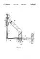
- FIG. 1is a simplified perspective view from above and to one side of an intramedullary nail and connected jig structure of the invention, showing distal and proximal nails that have been installed in a fractured tibia, the tibia being shown in phantom outline, and flesh profiles being omitted in the drawing;
- FIG. 2is an enlarged view in side elevation of the jig and nail of FIG. 1, partly broken-away to provide greater detail of distal and proximal coaction between nail and jig components;
- FIG. 3is a further enlarged section of distal outrigger structure of FIG. 2, taken at 3--3 of FIG. 2;
- FIG. 4is another view, to the scale of FIG. 3 and in partial section taken at 4--4 of FIG. 2, to show stabilizer structure of FIG. 2;
- FIG. 5is a view in side elevation and to a still-further enlarged scale, for a nail-size compensation component of the jig in FIG. 2;
- FIG. 6is a top view of the nail-size compensation component of FIG. 5;
- FIG. 7is a left-end view in elevation of the component of FIG. 5;
- FIG. 8is a perspective view of coacting parts of the distal end of FIG. 2, in readiness for correctly aligned drilling for bone-screw anchorage to blind holes of the installed intramedullary nail of FIG. 2;
- FIG. 9is a view similar to FIG. 1, for the same jig but different outrigger structure used to install two longitudinally spaced bone screws at mutually divergent orientations through bone, at the proximal end of the intramedullary nail of FIG. 2;
- FIG. 10is an enlarged view in perspective to show greater detail of outrigger, drill-guide and jig structure at the proximal end of the system;
- FIG. 11is a view similar to FIG. 3 to show a modification, the viewing aspect being opposite to that of FIG. 3;
- FIG. 12ms a perspective view of the modification of FIG. 11, taken from a three-quarter aspect on the distal end of the modification.
- FIG. 13is a perspective view of a jig that is similar to FIG. 2, for the case of modified structure that is specifically useful in application to a fractured femur;
- FIG. 14is a perspective view similar to FIG. 12, showing the distal end of outrigger structure of FIG. 13;
- FIG. 15is a fragmentary side elevation in partial section for stabilizer-rod positioning structure for the embodiment of FIGS. 13 and 14.
- the inventionis seen as jig structure, generally designated A, after having completed its job of correctly aligning, drilling and enabling installation of two bone screws 10, 10' at a location distal to a fracture 11 in a tibia 12 which has been reinforced by an elongate intramedullary nail 13; the bone screws 10, 10' will be understood to pass through spaced parallel bone-screw holes extending diametrically through nail 13.
- Two further bone screws 14, 14'are shown installed near the proximal end of the nail; the drilling for accommodation of bone screws 14, 14' is accomplished pursuant to later description, in connection with FIGS. 9 and 10.
- the jig structure Acomprises a plurality of separably and adjustably connectable components, better seen and identified in FIG. 2, where the intramedullary nail 13 is shown to comprise an elongate straight distally extending portion 15 for most of its length, there being a short bend 16 at an acute angle ⁇ near the proximal end 17 of the nail; two spaced diametrically extending bone-screw holes 18, 18' in the bent proximal end 17 are for accommodation of the screws 14, 14' to be described later in connection with FIGS. 9 and 10.
- the bend 16 between otherwise straight distal (15) and proximal (17) portions of nail 13will be understood to define a single plane of symmetry which will be referred to as the sagittal plane, containing the bent axis of the nail; and the distal bone-screw holes (as at 19 in FIG. 3) for bone screws 10, 10' will be understood to be normal to the sagittal plane.
- the proximal end of nail 13has keyed fit to jig A via the chuck 20 of an elongate locking rod 21, which is clamped by bolts 22 between front and back halves of a handle 23.
- a knob 24is rotatable to releasably secure the engagement of jig structure in accurately keyed relation to the proximal end of the nail.
- the central axis 23' of handle 23extends at a right angle to the axis of the proximal end 17 of the nail, and this central axis 23' lies in the sagittal plane of the connected nail.
- Confronting faces of the bolted halves of handle 23are grooved to establish a central axis 25 for slant-guided alignment of an elongate guide bar 26, wherein the central axis 25 of bar 26 intersects the central axis 23' of handle 23 and wherein axis 25 is also contained within the same sagittal plane of the nail; the slant angle ⁇ of intersection of axes 23', 25 is the complement of angle ⁇ , so that guide bar 26 is necessarily parallel to the elongate distal end portion 15 of the intramedullary nail.
- a locking knob 27 carried by handle 23includes a dowel portion which is selectively enterable in a given one out of a plurality of spaced transverses openings 28 in bar 26, the selection among openings 28 being dependent upon the length of the particular intramedullary nail 13 selected for implantation.
- openings 28be of limited depth in bar 26 and that the bottom of each opening 28 be conical, so that with a conically-tipped dowel secured by locking knob 27, the cone-to-cone engagement will assure an accurate, play-free location of handle 23.
- Distal outrigger structure 30is removably carried by guide bar 26 near the distal end of bar 26, to provide such lateral and downward offset of its lower end, from bar 26 and away from the sagittal plane, as to enable precise spaced parallel orientation and clamping of two elongate drill guides 31, in alignment with each of the respective bone-screw holes 19 near the distal end of the nail 13, all as best seen in FIG. 3; a knob 31' enables clamped positioning of the drill guides 31 to the laterally offset end of outrigger 30.
- outrigger 30mounts two spaced dowels 32 having precision entry in vertical guide bores through guide bar 26, and outrigger 30 is securely clamped by a knob-driven locking bolt 33 engaged to a suitably tapped vertical bore in guide bar 26, located between the two dowel pins.
- the vertical orientation of dowel pins 32 and of the guide bar 26 symmetrically with respect to the sagittal plane S of nail 13is clear from FIG. 3 and its legends.
- a further important component of the jig of FIG. 2is an elongate spacer or stabilizer rod 35, having a manipulating handle 36 at its upper end.
- rod 35is of constant diameter for guided stability in a vertical bore 37 in guide bar 26, in spaced adjacency to the mounting of outrigger 30.
- the diameter of rod 35is reduced to define a cylindrical portion 38 of length L which, as will later be explained, must be passed through a small surgical incision of flesh and local drilling of bone, to permit lower-end contact, as shown, with nail 13.
- the stabilizer rod 35is designed for precise positioning of its lower end with respect to guide bar 26 when in contact with nail 13, namely, when each drill guide 31 is truly aligned with a bone-screw hole 19 in the nail.
- spaced upper and lower circumferential grooves 39, 39'are formed in rod 35, and each of these grooves straddles upper and lower intercepts of rod 35 with the respective upper and lower faces of the rectangular section of guide bar 26.
- a shim 40 in the form of a clipis laterally applicable to guide bar 26, with provision for entry into the respective grooves 39, 39', to thereby limit the extent to which the lower end of stabilizer rod 35 can be projected toward nail 13. More detail as to shim 40 is obtained by further reference to the respective views of FIGS. 5, 6, and 7.
- the shim 40is of generally C-shape, being characterized upper and lower jaws 41, 42 which have vertically aligned side-entry slots 43, 43', of width less than the diameter of rod 35. Jaws 41, 42 extend integrally from a body 44 having upper and lower finger-grip recesses 45, 45' and also having a central through-hole 46 for tool-assisted removal from guide bar 26, if necessary. Inner-wall surfaces 41', 42', 44' of the C-shape are formed for unambiguous stabilizing engagement to corresponding sides of the section of guide bar 26.
- a spring detent 47has snap-engagement to the rod groove 39' upon application of shim 40 to guide bar 26, when rod 35 is positioned as shown in FIG. 4 to accept entry of the jaws 41, 42 into the respective grooves 39, 39'.
- the central axis of stabilizer rod 35will be in the alignment marked S in FIG. 5, signifying rod-35 inclusion in the same sagittal plane as has been elsewhere indicated for other components of the jig system.
- the word "shim”has been used for the component just described in connection with FIGS. 5, 6 and 7 because the thickness "T” shown in FIG. 5 is uniquely designed to position the lower end of stabilizer rod 35 at contact with nail 13, when drill guides are correctly aligned with respect to the distal bone-screw holes of the nail. But the precise thickness T will apply only for one of a series of possible section diameters of intramedullary nail. In the form shown, a 9-mm diameter nail 13 calls for a bottom-positioning limit for rod 35 that is unique, and therefore the thickness T in FIG. 5 is unique for tibia use with a 9-mm diameter nail.
- an intramedullary nail 13should be selected for nail diameter and overall length to serve the surgeon's purposes in the light of a particular fracture 11. Suitable surgery is performed to assure entry of the selected nail in direct alignment with the medullary cavity, but first it is recommended that, at least for distal-drilling purposes, the selected nail be assembled to the jig A to ascertain correct length adjustment (via dowel knob 27) at the correct one of the predrilled locations 28 along guide bar 26.
- Outrigger 30should be assembled to bar 26, along with two drill guides 31, securely setting the knob of bolt 33 and of the drill-guide clamp 31'. Additionally, stabilizer rod 35 should be inserted in bore 37 in guide bar 26 and the correctly selected shim fitment 40 should be assembled with its upper and lower jaws engaged in the upper and lower circumferential grooves 39, 39' of rod 35. Depression of rod 35 may or may not be necessary to bring rod 35 into contact with nail, at which point visual sighting or trocar passage down each drill-guide bore should confirm correct alignment with the respective bone-screw holes in nail 13. That done, all is in readiness for a correctly aligned drilling procedure, which of course must be preceded by correct surgical insertion of the intra-medullary nail 13 in the fractured bone.
- the guide bar 26After installing nail 13, whether the nail be solid or hollow, and with the handle 23 of the jig (A) locked in its keyed connection to the proximal end of the nail, the guide bar 26 should be introduced into the handle 23, moving the same to its pre-established point for locking-screw retention via knob 27 at one of the length-selection bores 28 in guide bar 26; for convenience, the upper surface of the guide bar 26 will be understood to have been inscribed with unit-length markers at unit spacing, corresponding to the length of intramedullary nails of an available set, and it will be further understood that engraved length designations, such as 280, 300 . . .
- the distal outrigger 30is next mounted on guide bar 26 so that it is positioned on the medial side of the tibia, and the screw guides 31 are inserted into the outrigger to determine proper locations for the incisions. An incision is then made beneath each screw guide, and the medial cortex is exposed in each incision by blunt dissection, taking care to avoid entrapment of or damage to the saphenous nerve and vein. The guides 31 are then advanced until they are in contact with the medial cortex. The clamp 31' on outrigger 30 is then tightened to hold the screw guides firmly in place.
- a drill guide(not shown) is inserted into the vertical bore 37 which has been previously described for stabilizer-rod (35) accommodation; an incision is made in the skin directly beneath this vertically oriented drill guide, and the anterior tibial cortex is exposed by blunt dissection.
- the drill guideis then advanced until its teeth are engaged onto the anterior border of the tibia; whereupon, a drill bit (e.g., of 4-mm diameter) is used to drill only the anterior cortex, and the drill bit is then removed.
- a drill bite.g., of 4-mm diameter
- the hole in the boneis tapered, so that a square-ended 4-mm T-handled reamer (not shown) is passed down the drill guide, to complete the hole down to the nail, and intervening debris is removed.
- the hand reamer and vertical drill guideare now removed and are replaced by entry of stabilizer rod 35 in vertical bore 37, the same being inserted to the point of reduced end (38) passage through the drilled hole in the cortex and into contact with nail 13.
- the stabilizing rod 35must be set in the correct position for the particular diameter of nail 13, and this is achieved by inserting the correct U-shaped spacer (with shim thickness T) 40 over guide bar 26, so that its forks engage into the two circumferential grooves 39, 39' of the stabilizer rod.
- a 4-mm drill guideis inserted into one of the guides 31, and is gently tapped to engage its distal-end teeth in the medial cortex.
- a drill stopis locked to a selected 4-mm drill bit at the proximal end.
- the assistantmay release the pressure on the T-handle of stabilizer rod 35.
- the locking screw length, from the base of the screw head,is determined by measuring the amount of drill bit protruding from the drill guide.
- the fractureshould be examined by x-radiation to determine whether there is any remaining distraction. If there is, conventional techniques are known, whereby to reduce the distraction, so that proximal locking can proceed.
- the two bone-screw holes 18, 18' for proximal bone-screw anchorageare on orthogonally related axes that are longitudinally spaced from each other; the proximal outrigger 52 therefore straddles guide bar 26 via its central body region, with its dowel pins 51 projecting downward from its central body region, and with provision for locking the outrigger to the guide bar by way of knob-driven means 53.
- Drilling access on the respective axes of these holes 18, 18'is at equal and opposite 45° inclinations with respect to the sagittal plane of nail 13, and therefore the proximal outrigger 52 provides at one of its ends for clamped mounting of a drill guide 54 in alignment with hole 18, and, at the other of its ends, for clamped mounting of a second drill guide 54' in alignment with the other proximal bone-screw hole 18'.
- Clamping access for setting the drill guides 54, 54'is identified at knobs 55, 55' in FIGS. 9 and 10.
- FIG. 10shows the relation of parts, for such checking at the proximal drilling sites, prior to nail 13 implantation. Not only does FIG.
- FIG. 10show that each of the drill guides 54, 54' may be checked for accuracy of registration with the respective proximal bone-screw holes 18, 18', but FIG. 10 additionally shows use of a trocar 56 inserted in one (54) of the drill guides and into stabilizing entry of the aligned bone-screw hole 18 (not visible in FIG. 10, but shown in FIG. 2).
- proximal-locking feature of the jigfor proximal drilling is very much as for the case of distal drilling although there is no need for a stabilizer rod 35 or its equivalent, since proximal drilling is so close to the location of jig connection.
- the proximal outrigger 52is mounted and locked to bar 26, and two screw guides 54 and 54' are clamped at 55, 55' to locate proper sites for the incisions.
- Two incisionsare made, one antero-lateral and one antero-medial, and the tibial cortex is exposed in each case by blunt dissection.
- the screw guides 54, 54'are advanced down to the cortex and locked in position via clamp knobs 55, 55'.
- a drill guideis inserted into one of the screw guides, and tapped gently to engage its distal teeth into the cortex. The drill bit is pushed down to the bone, and pressed against the cortex before drilling begins. Further procedures track those described for distal locking.
- the bone screwsare inserted after each hole is drilled, and their length is determined, as described for distal insertion of bone screws.
- FIGS. 11 and 12illustrates that the invention is also applicable to use of intramedullary nails wherein the axes of spaced parallel bone-screw holes 60, 60' for distal-end fixation to bone are in what may be called the sagittal plane, whether the nail is of bent or straight configuration, the point being that when the proximal end of the nail is keyed in its chucked connection to handle 23, the guide bar, here identified as 26', is parallel to the straight portion 15 of the intramedullary nail.
- the axes of the straight portion 15 of the nail, and of the jig guide bar 26', and of the bone-screw holes 60, 60'are thus all in the sagittal plane, marked S in FIG. 11.
- the distal end of guide bar 26'is seen to provide for the releasably clamped mounting of drill guides 31 for such drilled alignment.
- the distal end of bar 26'is so devised that a clamp block 61 may be clamped via knob actuation at 62 to support the precise spaced parallel relation of two drill guides 31.
- the confronting vertical faces of block 61 and of the uncut remainder 63 of the distal end of bar 26'are formed with matching cylindrically arcuate concavities for drill-guide support, and guide pins or dowels 64 carried by block 61 will be understood to have precision location and guidance in corresponding bores (not shown) in the distal-end portion 63 of bar 26'.
- An outrigger 65is generally as described for the outrigger 30 of the first embodiment, in that it has spaced parallel guide pins 32 and a locking knob 33 for accurate and secure outrigger mounting to the upper surface of guide bar 26'.
- the laterally and downwardly offset other end of the outriggeris devised for guidance and selective positioning of a spacer or stabilizer rod 35 in alignment with the central axis of the distal nail portion 15 and perpendicular to the sagittal plane.
- the same spacer rod 35(with its spaced grooves 39, 39' is again used for guidance in a bore 37' in the offset end of the outrigger, and a U-shaped shim fitment 40 is selected for assurance that when rod 35 is pressed into mechanical contact with nail 13, it can be known for sure that drill guides 31 are precisely aligned with the bone-screw holes 60, 60' of the nail.
- FIGS. 13 to 15is in many respects similar to that of FIGS. 11 and 12, except that the embodiment of FIGS. 13 to 15 is of specific utility in the blind-hole drilling of a fractured femur, wherein the intramedullary nail 113 is straight, with distal transverse bone-screw holes 160, 160' which are on parallel axes that are perpendicular to the central axis of nail 113 and thus determine a first geometric plane of symmetry.
- the handle A'has selectively locked and keyed connection to the proximal end of nail 113; handle A' extends perpendicular to nail 113 within the plane of symmetry, and handle A' is also perpendicular to elongate guide-bar structure 126, with means 127 whereby to selectively clamp structure 126 (i) in the indicated plane of symmetry and parallel to nail 113, and (ii) with such distally offsetting projection of structure 126 as to position its two drill guides 131/131', in potential (if not actual) aligning registration with the bone-screw holes 160, 160' of nail 113.
- Set screws on inclined axes 140/140', and accessible via the upper surface of jig bar 126,will be understood to provide adjusted axial positioning of drill guides 130/130', respectively.
- bar structure 126The distal end of bar structure 126 is shown carrying the upper end of outrigger structure 165 which has a vertical-plane mounting face that is in clamped abutment with one of the vertical faces of the constant cross-section of guide-bar structure 126, being clamped by knob-headed bolts 132 which seat against the opposite vertical face of structure 126.
- bolts 132have smooth cylindrical dowel-like fit to transverse bores in bar structure 126 and that only their threaded distal ends engage threaded bores in the confronting upper end of the outrigger structure 165.
- outrigger structure 165has a guide bore on an axis perpendicular to the axis of nail 113 and also perpendicular to the indicated first geometric plane of symmetry, being shown to mount a guide sleeve 135' for slidable guidance of a stabilizing rod 135.
- Rod 135has a manipulating handle 136 at its proximal end, and a reduced distal end 138 for stabilizing contact with nail 113.
- a spacer element 100has a body with three pairs of upstanding feet 101/101', 102/102', and 103/103', which enable precise positioning of the distal end 138 of rod 135, specific to the outer radius of the nail 113 it is to abut.
- the first and second pairs of feet 101/101' and 102/102'will be understood to be spaced at distance T 1 for accurate friction fit to the opposing parallel faces of outrigger 165, at guide-sleeve (135') passage therethrough.
- the third pair (103/103') of upstanding feetare at reduced spacing T 2 from each other, wherein T 2 is less than the diameter of stabilizing rod 135 thus enabling entry of feet 103/103' into an axially locating circumferential groove 139 in rod 135; the thickness T 3 of feet 103/103' has sufficient match to the axial extent of groove 139 to permit a sliding precision fit to groove 139 and to provide a well located positioning of groove 139 with respect to the lower or distal end of the outrigger structure 165.
- legs 103/103'have a fixed offset from the two pairs 101/101', 102/102' which engage the distal end of the outrigger; in FIG. 15, the dimension X will be understood to designate this fixed offset. It will further be understood that the dimension X, although fixed, is nevertheless specifically related to the radius R of the intramedullary nail 113 with which stabilizer rod 135 and spacer element 100 are to be used, for a guarantee of drill-guide (131) alignments with holes 160/160' when nail 113 is abutted by the distal end 138 of rod 135.
- the spacer 100 of FIGS. 13 to 15is unique to a particular nail diameter (2R), and permanent indicia of the particular nail diameter are preferably inscribed on each spacer 100 of a plurality to serve a range of nail diameters.
- Assembly of the stabilizer system of FIGS. 14 and 15first involves insertion of the guide sleeve 135' in the precision bore of the distal end of the outrigger; a set screw 104 enables releasable retention of this assembly.
- stabilizer rod 135is inserted into guide sleeve 135'.
- the spacer element 100is applied to the distal end of the outrigger, the stabilizer rod 135 being manipulated as necessary to assure locating engagement of feet 103/103' in groove 139.
- Spring detents 105 (in leg 101') and 106 (in leg 103')respectively engage guide sleeve 135' and the bottom of groove 139 to releasably retain spacer-100 assembly to the outrigger.
- the clamp bolts 132are shown on spaced axes that symmetrically straddle the vertical axis of the drill guide 131', thus assuring that the reduced end 138 of the stabilizer rod will contact nail 113 in the geometric plane which is defined by the axis of nail hole 160' and the stabilizer-rod axis.
- Thisis a geometric plane of symmetry dividing the entire outrigger structure, perpendicular to the plane of symmetry defined by jig bar 126, nail 113 and the nail holes 160/160'.
Landscapes
- Health & Medical Sciences (AREA)
- Surgery (AREA)
- Life Sciences & Earth Sciences (AREA)
- Medical Informatics (AREA)
- Animal Behavior & Ethology (AREA)
- Orthopedic Medicine & Surgery (AREA)
- Oral & Maxillofacial Surgery (AREA)
- Engineering & Computer Science (AREA)
- Biomedical Technology (AREA)
- Heart & Thoracic Surgery (AREA)
- Dentistry (AREA)
- Molecular Biology (AREA)
- Nuclear Medicine, Radiotherapy & Molecular Imaging (AREA)
- General Health & Medical Sciences (AREA)
- Public Health (AREA)
- Veterinary Medicine (AREA)
- Surgical Instruments (AREA)
- Prostheses (AREA)
- External Artificial Organs (AREA)
- Drilling And Boring (AREA)
- Eye Examination Apparatus (AREA)
Abstract
Description
Claims (41)
Priority Applications (1)
| Application Number | Priority Date | Filing Date | Title |
|---|---|---|---|
| US08/401,094US5620449A (en) | 1994-07-28 | 1995-03-08 | Mechanical system for blind nail-hole alignment of bone screws |
Applications Claiming Priority (4)
| Application Number | Priority Date | Filing Date | Title |
|---|---|---|---|
| ITVR94A0069 | 1994-07-28 | ||
| IT94VR000069AIT1268313B1 (en) | 1994-07-28 | 1994-07-28 | MECHANICAL EQUIPMENT FOR CENTERING BLIND HOLES FOR BONE SCREWS OF INTRAMIDOLLAR NAILS |
| US31062294A | 1994-09-22 | 1994-09-22 | |
| US08/401,094US5620449A (en) | 1994-07-28 | 1995-03-08 | Mechanical system for blind nail-hole alignment of bone screws |
Related Parent Applications (1)
| Application Number | Title | Priority Date | Filing Date |
|---|---|---|---|
| US31062294AContinuation-In-Part | 1994-07-28 | 1994-09-22 |
Publications (1)
| Publication Number | Publication Date |
|---|---|
| US5620449Atrue US5620449A (en) | 1997-04-15 |
Family
ID=11427893
Family Applications (1)
| Application Number | Title | Priority Date | Filing Date |
|---|---|---|---|
| US08/401,094Expired - LifetimeUS5620449A (en) | 1994-07-28 | 1995-03-08 | Mechanical system for blind nail-hole alignment of bone screws |
Country Status (24)
| Country | Link |
|---|---|
| US (1) | US5620449A (en) |
| EP (1) | EP0772420B1 (en) |
| JP (1) | JP3180223B2 (en) |
| KR (1) | KR100269983B1 (en) |
| CN (1) | CN1060931C (en) |
| AT (1) | ATE196982T1 (en) |
| AU (1) | AU686837B2 (en) |
| BR (1) | BR9508452A (en) |
| CA (1) | CA2118366C (en) |
| CZ (1) | CZ292954B6 (en) |
| DE (3) | DE29522285U1 (en) |
| DK (1) | DK0772420T3 (en) |
| ES (1) | ES2151964T3 (en) |
| GR (1) | GR3035238T3 (en) |
| HU (1) | HU219014B (en) |
| IT (1) | IT1268313B1 (en) |
| NO (1) | NO324340B1 (en) |
| PE (1) | PE29696A1 (en) |
| PL (1) | PL180386B1 (en) |
| PT (1) | PT772420E (en) |
| SK (1) | SK282631B6 (en) |
| TR (1) | TR199500921A2 (en) |
| WO (1) | WO1996003085A1 (en) |
| ZA (1) | ZA956251B (en) |
Cited By (113)
| Publication number | Priority date | Publication date | Assignee | Title |
|---|---|---|---|---|
| US5766179A (en)* | 1997-03-05 | 1998-06-16 | Orthofix S.R.L. | Mechanical system for blind nail-hole alignment of bone screws |
| US5833693A (en)* | 1997-05-02 | 1998-11-10 | Abrahami; Israel | Drill guide |
| US6039742A (en)* | 1996-05-04 | 2000-03-21 | Synthes (U.S.A.) | Alignment device for locking the base part of intramedullary nails |
| US6342057B1 (en) | 2000-04-28 | 2002-01-29 | Synthes (Usa) | Remotely aligned surgical drill guide |
| US6379360B1 (en)* | 1998-03-11 | 2002-04-30 | Synthes (Usa) | Spiral blade insertion instrument |
| US6379364B1 (en) | 2000-04-28 | 2002-04-30 | Synthes (Usa) | Dual drill guide for a locking bone plate |
| US6423061B1 (en) | 2000-03-14 | 2002-07-23 | Amei Technologies Inc. | High tibial osteotomy method and apparatus |
| US20020111629A1 (en)* | 1999-05-27 | 2002-08-15 | Jonathan Phillips | Pediatric intramedullary nail and method |
| US6500177B1 (en) | 1998-05-19 | 2002-12-31 | Synthes (Usa) | Telescopic body for an external fixation system |
| US6656189B1 (en) | 2000-05-25 | 2003-12-02 | Synthes (Usa) | Radiolucent aiming guide |
| US6673076B2 (en)* | 2000-11-13 | 2004-01-06 | Benoist Girard Sas | Targeting apparatus for use in resectioning a femur when performing transfemoral osteotomy |
| US6678562B1 (en) | 2000-01-12 | 2004-01-13 | Amei Technologies Inc. | Combined tissue/bone growth stimulator and external fixation device |
| US6746453B2 (en) | 2000-11-13 | 2004-06-08 | Benoist Girard Sas | Targeting apparatus for use in performing transfemoral osteotomy |
| US6783535B2 (en) | 2000-11-13 | 2004-08-31 | Benoist Girard Sas | Targeting apparatus for use in performing endofemoral osteotomy surgery |
| US20040215204A1 (en)* | 2002-03-28 | 2004-10-28 | Davison Dale George | Bone fastener targeting and compression/distraction device for an intramedullary nail and method of use |
| US20050261698A1 (en)* | 2004-05-19 | 2005-11-24 | Sean Powell | Snap-lock for drill sleeve |
| US20060015101A1 (en)* | 2004-07-15 | 2006-01-19 | Wright Medical Technology, Inc. | Intramedullary fixation assembly and devices and methods for installing the same |
| US20060015123A1 (en)* | 2004-07-15 | 2006-01-19 | Wright Medical Technology, Inc. | Guide assembly for intramedullary fixation and method of using the same |
| US20060030839A1 (en)* | 2004-07-21 | 2006-02-09 | Solco Biomedical Co., Ltd. | Pedicle screw and operating device thereof |
| US20060064106A1 (en)* | 2004-09-23 | 2006-03-23 | Fernandez Alberto A | Coplanar X-ray guided aiming arm for locking of intramedullary nails |
| US20060116679A1 (en)* | 2004-11-30 | 2006-06-01 | Stryker Trauma Sa | Bone plating implants, instruments and methods |
| US20060161168A1 (en)* | 2003-07-14 | 2006-07-20 | Romano Matthys | Targeting device |
| US20060200144A1 (en)* | 2000-09-22 | 2006-09-07 | Warburton Mark J | Intramedullary interlocking fixation devices for the distal radius |
| US20060229603A1 (en)* | 2005-03-18 | 2006-10-12 | Olsen Ron A | Adjustable splint for osteosynthesis with modular joint |
| US20060229605A1 (en)* | 2005-03-18 | 2006-10-12 | Olsen Ron A | Adjustable splint for osteosynthesis with incrementing assembly for adjustment in predetermined increments |
| US20060241619A1 (en)* | 2005-04-20 | 2006-10-26 | Daniel Cerundolo | Method and apparatus for surgical repair |
| WO2007035772A1 (en)* | 2005-09-19 | 2007-03-29 | Synthes (U.S.A.) | Orthopedic implant insertion handle and aiming guide |
| US20070162028A1 (en)* | 2005-12-09 | 2007-07-12 | Jesse Jackson | Cannulated screw |
| US20070202603A1 (en)* | 2006-02-27 | 2007-08-30 | Steven Wayne Counts | Apparatus and method for sampling and correcting fluids |
| US20080125782A1 (en)* | 2006-11-29 | 2008-05-29 | Disc Dynamics, Inc. | Method and apparatus for removing an extension from a prosthesis |
| US20090157077A1 (en)* | 2007-12-17 | 2009-06-18 | Wright Medical Technology, Inc. | Guide assembly for intramedullary fixation and method of using the same |
| US20090318926A1 (en)* | 2008-06-20 | 2009-12-24 | Depuy Products, Inc. | Adjustable angle targeting device for an intramedullary nail and method of use |
| US20100094347A1 (en)* | 2005-05-18 | 2010-04-15 | Nelson Charles L | Fracture fixation device, tools and methods |
| US20100121324A1 (en)* | 2008-06-24 | 2010-05-13 | Jeff Tyber | Fixation system, an intramedullary fixation assembly and method of use |
| US7727240B1 (en)* | 2006-02-15 | 2010-06-01 | Blake Benton | Method and system for securing an intramedullary nail |
| US20100137873A1 (en)* | 2004-11-03 | 2010-06-03 | Grady Jr Mark P | Aiming Arm for Bone Plates |
| US20100256639A1 (en)* | 2008-06-24 | 2010-10-07 | Jeff Tyber | Fixation system, an intramedullary fixation assembly and method of use |
| US20100256638A1 (en)* | 2008-06-24 | 2010-10-07 | Jeff Tyber | Intraosseous intramedullary fixation assembly and method of use |
| US20100274245A1 (en)* | 2003-11-21 | 2010-10-28 | Eduardo Gonzalez-Hernandez | Fracture fixation system |
| US7846162B2 (en) | 2005-05-18 | 2010-12-07 | Sonoma Orthopedic Products, Inc. | Minimally invasive actuable bone fixation devices |
| US20100324556A1 (en)* | 2008-06-24 | 2010-12-23 | Jeff Tyber | Fixation system, an intramedullary fixation assembly and method of use |
| US20110022087A1 (en)* | 2005-04-20 | 2011-01-27 | Arthroscopic Innnovations LLC | Suture fixation device and method for surgical repair |
| US20110054550A1 (en)* | 2009-08-26 | 2011-03-03 | Metzinger Anthony J | Method for implanting a hip fracture nail system |
| US20110054473A1 (en)* | 2008-07-09 | 2011-03-03 | Amei Technologies, Inc. | Ankle arthrodesis nail and outrigger assembly |
| US20110060336A1 (en)* | 2009-09-04 | 2011-03-10 | Ellipse Technologies, Inc. | Bone growth device and method |
| US7909825B2 (en) | 2006-11-22 | 2011-03-22 | Sonoma Orthepedic Products, Inc. | Fracture fixation device, tools and methods |
| US20110152943A1 (en)* | 2009-12-22 | 2011-06-23 | Eduardo Gonzalez-Hernandez | Bone plate and tool assembly and method for use thereof |
| US20110213367A1 (en)* | 2008-06-24 | 2011-09-01 | Jeff Tyber | Intramedullary fixation screw, a fixation system, and method of fixation of the subtalar joint |
| US20130152358A1 (en)* | 2011-12-16 | 2013-06-20 | Chrysler Group Llc | Guidance tool for adjusting position of autonomous cruise control assembly |
| US8469999B2 (en) | 2008-04-17 | 2013-06-25 | Eduardo Gonzalez-Hernandez | Soft tissue attachment system and clip |
| US8715282B2 (en) | 2011-02-14 | 2014-05-06 | Ellipse Technologies, Inc. | System and method for altering rotational alignment of bone sections |
| US8764808B2 (en) | 2008-03-10 | 2014-07-01 | Eduardo Gonzalez-Hernandez | Bone fixation system |
| US8870963B2 (en) | 2010-10-27 | 2014-10-28 | Toby Orthopaedics, Inc. | System and method for fracture replacement of comminuted bone fractures or portions thereof adjacent bone joints |
| WO2013101880A3 (en)* | 2011-12-30 | 2015-01-08 | DePuy Synthes Products, LLC | Single patient use depth gauge |
| US8961516B2 (en) | 2005-05-18 | 2015-02-24 | Sonoma Orthopedic Products, Inc. | Straight intramedullary fracture fixation devices and methods |
| US8961573B2 (en) | 2010-10-05 | 2015-02-24 | Toby Orthopaedics, Inc. | System and method for facilitating repair and reattachment of comminuted bone portions |
| US8968324B2 (en) | 2011-10-27 | 2015-03-03 | Kettering University | Adjustable jig and method for targeting interlocking holes of an intramedullary nail |
| US8997750B1 (en)* | 2011-10-26 | 2015-04-07 | Everardo Menchaca | Immobilization device for radiation therapy treatment |
| US9017329B2 (en) | 2008-06-24 | 2015-04-28 | Extremity Medical, Llc | Intramedullary fixation assembly and method of use |
| US9060820B2 (en) | 2005-05-18 | 2015-06-23 | Sonoma Orthopedic Products, Inc. | Segmented intramedullary fracture fixation devices and methods |
| US9155582B2 (en) | 2013-01-30 | 2015-10-13 | DePuy Synthes Products, Inc. | Aiming instrument |
| US9155574B2 (en) | 2006-05-17 | 2015-10-13 | Sonoma Orthopedic Products, Inc. | Bone fixation device, tools and methods |
| US20150351821A1 (en)* | 2014-06-04 | 2015-12-10 | Biomet Manufacturing, Llc | Orthopaedic aiming device for compound screw trajectories |
| US9254154B2 (en) | 2011-03-03 | 2016-02-09 | Toby Orthopaedic, Inc. | Anterior lesser tuberosity fixed angle fixation device and method of use associated therewith |
| US9271772B2 (en) | 2011-10-27 | 2016-03-01 | Toby Orthopaedics, Inc. | System and method for fracture replacement of comminuted bone fractures or portions thereof adjacent bone joints |
| US9283008B2 (en) | 2012-12-17 | 2016-03-15 | Toby Orthopaedics, Inc. | Bone plate for plate osteosynthesis and method for use thereof |
| US9289220B2 (en) | 2008-06-24 | 2016-03-22 | Extremity Medical Llc | Intramedullary fixation assembly and method of use |
| US9333014B2 (en) | 2013-03-15 | 2016-05-10 | Eduardo Gonzalez-Hernandez | Bone fixation and reduction apparatus and method for fixation and reduction of a distal bone fracture and malunion |
| US9402667B2 (en) | 2011-11-09 | 2016-08-02 | Eduardo Gonzalez-Hernandez | Apparatus and method for use of the apparatus for fracture fixation of the distal humerus |
| US20170202566A1 (en)* | 2014-07-15 | 2017-07-20 | Ot Medizintechnik Gmbh | Positioning device for securing an intramedullary nail in a long bone |
| US9730797B2 (en) | 2011-10-27 | 2017-08-15 | Toby Orthopaedics, Inc. | Bone joint replacement and repair assembly and method of repairing and replacing a bone joint |
| US9770278B2 (en) | 2014-01-17 | 2017-09-26 | Arthrex, Inc. | Dual tip guide wire |
| US9814499B2 (en) | 2014-09-30 | 2017-11-14 | Arthrex, Inc. | Intramedullary fracture fixation devices and methods |
| US9949796B2 (en) | 2011-12-30 | 2018-04-24 | DePuy Synthes Products, Inc. | Round depth gauge |
| US10016220B2 (en) | 2011-11-01 | 2018-07-10 | Nuvasive Specialized Orthopedics, Inc. | Adjustable magnetic devices and methods of using same |
| US10039661B2 (en) | 2006-10-20 | 2018-08-07 | Nuvasive Specialized Orthopedics, Inc. | Adjustable implant and method of use |
| US10238427B2 (en) | 2015-02-19 | 2019-03-26 | Nuvasive Specialized Orthopedics, Inc. | Systems and methods for vertebral adjustment |
| US10271885B2 (en) | 2014-12-26 | 2019-04-30 | Nuvasive Specialized Orthopedics, Inc. | Systems and methods for distraction |
| US10349995B2 (en) | 2007-10-30 | 2019-07-16 | Nuvasive Specialized Orthopedics, Inc. | Skeletal manipulation method |
| US10357314B2 (en) | 2015-07-08 | 2019-07-23 | Stryker European Holdings I, Llc | Instrumentation and method for repair of a bone fracture |
| US10405891B2 (en) | 2010-08-09 | 2019-09-10 | Nuvasive Specialized Orthopedics, Inc. | Maintenance feature in magnetic implant |
| US10478232B2 (en) | 2009-04-29 | 2019-11-19 | Nuvasive Specialized Orthopedics, Inc. | Interspinous process device and method |
| US10517643B2 (en) | 2009-02-23 | 2019-12-31 | Nuvasive Specialized Orthopedics, Inc. | Non-invasive adjustable distraction system |
| US10617453B2 (en) | 2015-10-16 | 2020-04-14 | Nuvasive Specialized Orthopedics, Inc. | Adjustable devices for treating arthritis of the knee |
| US10660675B2 (en) | 2010-06-30 | 2020-05-26 | Nuvasive Specialized Orthopedics, Inc. | External adjustment device for distraction device |
| US10729470B2 (en) | 2008-11-10 | 2020-08-04 | Nuvasive Specialized Orthopedics, Inc. | External adjustment device for distraction device |
| US10743794B2 (en) | 2011-10-04 | 2020-08-18 | Nuvasive Specialized Orthopedics, Inc. | Devices and methods for non-invasive implant length sensing |
| US10751094B2 (en) | 2013-10-10 | 2020-08-25 | Nuvasive Specialized Orthopedics, Inc. | Adjustable spinal implant |
| US10835290B2 (en) | 2015-12-10 | 2020-11-17 | Nuvasive Specialized Orthopedics, Inc. | External adjustment device for distraction device |
| US10874433B2 (en) | 2017-01-30 | 2020-12-29 | Stryker European Holdings I, Llc | Strut attachments for external fixation frame |
| US10918425B2 (en) | 2016-01-28 | 2021-02-16 | Nuvasive Specialized Orthopedics, Inc. | System and methods for bone transport |
| US11076896B2 (en) | 2016-01-20 | 2021-08-03 | Ot Medizintechnik Gmbh | Positioning-device module for releasable connection to a positioning device, positioning device and set |
| US11191579B2 (en) | 2012-10-29 | 2021-12-07 | Nuvasive Specialized Orthopedics, Inc. | Adjustable devices for treating arthritis of the knee |
| US11202707B2 (en) | 2008-03-25 | 2021-12-21 | Nuvasive Specialized Orthopedics, Inc. | Adjustable implant system |
| US11246694B2 (en) | 2014-04-28 | 2022-02-15 | Nuvasive Specialized Orthopedics, Inc. | System for informational magnetic feedback in adjustable implants |
| USRE49061E1 (en) | 2012-10-18 | 2022-05-10 | Nuvasive Specialized Orthopedics, Inc. | Intramedullary implants for replacing lost bone |
| US11357549B2 (en) | 2004-07-02 | 2022-06-14 | Nuvasive Specialized Orthopedics, Inc. | Expandable rod system to treat scoliosis and method of using the same |
| US11357547B2 (en) | 2014-10-23 | 2022-06-14 | Nuvasive Specialized Orthopedics Inc. | Remotely adjustable interactive bone reshaping implant |
| US11426220B2 (en) | 2017-10-11 | 2022-08-30 | Howmedica Osteonics Corp. | Humeral fixation plate guides |
| US20220296284A1 (en)* | 2021-03-22 | 2022-09-22 | Acumed Llc | Targeting device for screw insertion in distal end of bone |
| US11504171B2 (en) | 2019-07-26 | 2022-11-22 | Glw, Inc. | Intramedullary rod with intrabody outrigger interface |
| US11577097B2 (en) | 2019-02-07 | 2023-02-14 | Nuvasive Specialized Orthopedics, Inc. | Ultrasonic communication in medical devices |
| US11589901B2 (en) | 2019-02-08 | 2023-02-28 | Nuvasive Specialized Orthopedics, Inc. | External adjustment device |
| US11696836B2 (en) | 2013-08-09 | 2023-07-11 | Nuvasive, Inc. | Lordotic expandable interbody implant |
| US11737787B1 (en) | 2021-05-27 | 2023-08-29 | Nuvasive, Inc. | Bone elongating devices and methods of use |
| US11766252B2 (en) | 2013-07-31 | 2023-09-26 | Nuvasive Specialized Orthopedics, Inc. | Noninvasively adjustable suture anchors |
| US11801187B2 (en) | 2016-02-10 | 2023-10-31 | Nuvasive Specialized Orthopedics, Inc. | Systems and methods for controlling multiple surgical variables |
| US11806054B2 (en) | 2021-02-23 | 2023-11-07 | Nuvasive Specialized Orthopedics, Inc. | Adjustable implant, system and methods |
| US11839410B2 (en) | 2012-06-15 | 2023-12-12 | Nuvasive Inc. | Magnetic implants with improved anatomical compatibility |
| US11857226B2 (en) | 2013-03-08 | 2024-01-02 | Nuvasive Specialized Orthopedics | Systems and methods for ultrasonic detection of device distraction |
| US11925389B2 (en) | 2008-10-13 | 2024-03-12 | Nuvasive Specialized Orthopedics, Inc. | Spinal distraction system |
| US12023073B2 (en) | 2021-08-03 | 2024-07-02 | Nuvasive Specialized Orthopedics, Inc. | Adjustable implant |
| US12213708B2 (en) | 2020-09-08 | 2025-02-04 | Nuvasive Specialized Orthopedics, Inc. | Remote control module for adjustable implants |
Families Citing this family (23)
| Publication number | Priority date | Publication date | Assignee | Title |
|---|---|---|---|---|
| US5962183A (en)* | 1995-11-27 | 1999-10-05 | Clariant Finance (Bvi) Limited | Metal ion reduction in photoresist compositions by chelating ion exchange resin |
| ATE250390T1 (en)* | 1997-04-11 | 2003-10-15 | Rosas Fernando Colchero | TREATMENT SYSTEM FOR FRACTURES AND OTHER INJURIES OF THE FEMUR, TIBIA AND HUMERUS |
| GB9823974D0 (en) | 1998-11-02 | 1998-12-30 | Grampian Healthcare National H | Fracture treatment |
| DE19945612C1 (en)* | 1999-09-23 | 2001-05-10 | Aesculap Ag & Co Kg | Reduction tools |
| EP1099413A1 (en)* | 1999-11-09 | 2001-05-16 | Schlumbohm Medizin-Labor-Technologie GmbH | Aiming device for distal locking of an intramedullary nail |
| DE20003053U1 (en)* | 2000-02-19 | 2001-06-28 | Howmedica GmbH, 24232 Schönkirchen | Locking nail and aiming device |
| WO2003043508A1 (en)* | 2001-11-19 | 2003-05-30 | Sanatmetal Kft. | Equipment for the fixation of intramedullary nails |
| US6702823B2 (en)* | 2002-01-14 | 2004-03-09 | Hit Medica S.R.L. | Device for identifying the position of intramedullary nail securement screw holes |
| DE10227379B4 (en)* | 2002-06-20 | 2005-12-08 | Stryker Trauma Gmbh | Implantation system and target device for it |
| US8162942B2 (en) | 2004-03-31 | 2012-04-24 | Orthofix S.R.L. | Intramedullary nail comprising elements of shape-memory material |
| EP1582162A1 (en) | 2004-03-31 | 2005-10-05 | Orthofix International B.V. | Intramedullary nail provided with expansion fixing means comprising at least one element of shape-retention material |
| EP1582164A1 (en) | 2004-03-31 | 2005-10-05 | Orthofix International B.V. | Intramedullary nail comprising a stem whereon longitudinal portions are provided driving elements of shape-memory material |
| EP1582163A1 (en) | 2004-03-31 | 2005-10-05 | Orthofix International B.V. | Intramedullary nail comprising an helical element of shape-memory material |
| EP1759643A1 (en) | 2005-08-30 | 2007-03-07 | Orthofix International B.V. | Targeting device for intramedullary nails |
| DE202009012712U1 (en) | 2009-09-18 | 2010-03-25 | Icm - Institut Chemnitzer Maschinen- Und Anlagenbau E.V. | Mechanical device for a fixed positioning and its readjustment for the elimination of positional deviations during the locking of implants |
| GB2475491A (en)* | 2009-11-18 | 2011-05-25 | Biomet Uk Ltd | Alignment tool for a femoral drill guide |
| EP2471478A1 (en) | 2010-12-31 | 2012-07-04 | ORTHOFIX S.r.l. | Intramedullary nail with shape memory elements for long bones |
| AU2012225496B2 (en)* | 2011-03-07 | 2016-09-22 | Conventus Orthopaedics, Inc. | Apparatus and methods for bone repair preparation |
| GB2495331A (en)* | 2011-10-07 | 2013-04-10 | Levant Orthopaedics Ltd | Mechanical locator and positioning device for locking intramedullary nails |
| KR101722252B1 (en)* | 2016-03-18 | 2017-04-03 | 이동훈 | Intramedullary nail having an anti-tilting fuction |
| US10251682B2 (en) | 2017-03-22 | 2019-04-09 | DePuy Synthes Products, Inc. | Distal radius nail |
| TR201705176A2 (en)* | 2017-04-06 | 2018-10-22 | Kayahan Karaytug | Tibia intramedullary nail. |
| CN113413205B (en)* | 2021-05-25 | 2022-03-18 | 温州医科大学附属第二医院(温州医科大学附属育英儿童医院) | Medical screw holding device |
Citations (4)
| Publication number | Priority date | Publication date | Assignee | Title |
|---|---|---|---|---|
| WO1992001422A1 (en)* | 1990-07-24 | 1992-02-06 | British Technology Group Plc | Interlocking intramedullary nails |
| DE4240277A1 (en)* | 1991-12-03 | 1993-06-09 | Dietmar Dr.Med. 5000 Koeln De Pennig | Aiming device for locking nail - comprises straight, unbent locking nail with auxiliary rail fixable in area of guide holes to bone by fixture pins |
| US5346496A (en)* | 1991-12-13 | 1994-09-13 | Dietmar Pennig | Drill-device for alignment of a bone screw driven into the neck of a femur |
| US5433720A (en)* | 1992-09-22 | 1995-07-18 | Orthofix S.R.L. | Centering means for holes of intramedullary nails |
Family Cites Families (3)
| Publication number | Priority date | Publication date | Assignee | Title |
|---|---|---|---|---|
| US4667664A (en)* | 1985-01-18 | 1987-05-26 | Richards Medical Company | Blind hole targeting device for orthopedic surgery |
| FR2647006B1 (en)* | 1989-05-22 | 1996-02-23 | Zimmer Sa | DEVICES FOR MOUNTING A REINFORCEMENT NAIL AND METHOD USING THE SAME |
| IT1253255B (en)* | 1991-08-02 | 1995-07-14 | Orthofix Srl | SURGICAL INSTRUMENTS FOR IMPLANTATION, ON-SITE FIXING AND EXTRACTION OF INTERMIDOLLAR NAILS |
- 1994
- 1994-07-28ITIT94VR000069Apatent/IT1268313B1/enactiveIP Right Grant
- 1994-10-18CACA002118366Apatent/CA2118366C/ennot_activeExpired - Lifetime
- 1995
- 1995-03-08USUS08/401,094patent/US5620449A/ennot_activeExpired - Lifetime
- 1995-07-12JPJP50561296Apatent/JP3180223B2/ennot_activeExpired - Lifetime
- 1995-07-12ATAT95924473Tpatent/ATE196982T1/enactive
- 1995-07-12DEDE29522285Upatent/DE29522285U1/ennot_activeExpired - Lifetime
- 1995-07-12ESES95924473Tpatent/ES2151964T3/ennot_activeExpired - Lifetime
- 1995-07-12EPEP95924473Apatent/EP0772420B1/ennot_activeExpired - Lifetime
- 1995-07-12PLPL95318355Apatent/PL180386B1/enunknown
- 1995-07-12BRBR9508452Apatent/BR9508452A/ennot_activeIP Right Cessation
- 1995-07-12HUHU9700263Apatent/HU219014B/enunknown
- 1995-07-12DEDE69519169Tpatent/DE69519169T2/ennot_activeExpired - Lifetime
- 1995-07-12CZCZ1997208Apatent/CZ292954B6/ennot_activeIP Right Cessation
- 1995-07-12DKDK95924473Tpatent/DK0772420T3/enactive
- 1995-07-12KRKR1019970700522Apatent/KR100269983B1/ennot_activeExpired - Lifetime
- 1995-07-12DEDE29521736Upatent/DE29521736U1/ennot_activeExpired - Lifetime
- 1995-07-12WOPCT/IB1995/000552patent/WO1996003085A1/enactiveIP Right Grant
- 1995-07-12SKSK114-97Apatent/SK282631B6/ennot_activeIP Right Cessation
- 1995-07-12PTPT95924473Tpatent/PT772420E/enunknown
- 1995-07-12AUAU28967/95Apatent/AU686837B2/ennot_activeCeased
- 1995-07-25CNCN95115312Apatent/CN1060931C/ennot_activeExpired - Lifetime
- 1995-07-26PEPE1995274751Apatent/PE29696A1/ennot_activeApplication Discontinuation
- 1995-07-27ZAZA956251Apatent/ZA956251B/enunknown
- 1995-07-28TRTR95/00921Apatent/TR199500921A2/enunknown
- 1997
- 1997-01-27NONO19970344Apatent/NO324340B1/ennot_activeIP Right Cessation
- 2001
- 2001-01-15GRGR20010400054Tpatent/GR3035238T3/enunknown
Patent Citations (4)
| Publication number | Priority date | Publication date | Assignee | Title |
|---|---|---|---|---|
| WO1992001422A1 (en)* | 1990-07-24 | 1992-02-06 | British Technology Group Plc | Interlocking intramedullary nails |
| DE4240277A1 (en)* | 1991-12-03 | 1993-06-09 | Dietmar Dr.Med. 5000 Koeln De Pennig | Aiming device for locking nail - comprises straight, unbent locking nail with auxiliary rail fixable in area of guide holes to bone by fixture pins |
| US5346496A (en)* | 1991-12-13 | 1994-09-13 | Dietmar Pennig | Drill-device for alignment of a bone screw driven into the neck of a femur |
| US5433720A (en)* | 1992-09-22 | 1995-07-18 | Orthofix S.R.L. | Centering means for holes of intramedullary nails |
Cited By (259)
| Publication number | Priority date | Publication date | Assignee | Title |
|---|---|---|---|---|
| US6039742A (en)* | 1996-05-04 | 2000-03-21 | Synthes (U.S.A.) | Alignment device for locking the base part of intramedullary nails |
| US6027506A (en)* | 1997-03-05 | 2000-02-22 | Orthofix, S.R.L. | Mechanical system for blind nail-hole alignment of bone screws |
| US5766179A (en)* | 1997-03-05 | 1998-06-16 | Orthofix S.R.L. | Mechanical system for blind nail-hole alignment of bone screws |
| US5833693A (en)* | 1997-05-02 | 1998-11-10 | Abrahami; Israel | Drill guide |
| US6379360B1 (en)* | 1998-03-11 | 2002-04-30 | Synthes (Usa) | Spiral blade insertion instrument |
| US6500177B1 (en) | 1998-05-19 | 2002-12-31 | Synthes (Usa) | Telescopic body for an external fixation system |
| US7008425B2 (en)* | 1999-05-27 | 2006-03-07 | Jonathan Phillips | Pediatric intramedullary nail and method |
| US20080147067A1 (en)* | 1999-05-27 | 2008-06-19 | Jonathan Phillips | Pediatric intramedullary nail and method |
| US20020111629A1 (en)* | 1999-05-27 | 2002-08-15 | Jonathan Phillips | Pediatric intramedullary nail and method |
| US7842036B2 (en)* | 1999-05-27 | 2010-11-30 | Jonathan Phillips | Pediatric intramedullary nail and method |
| US6678562B1 (en) | 2000-01-12 | 2004-01-13 | Amei Technologies Inc. | Combined tissue/bone growth stimulator and external fixation device |
| US6423061B1 (en) | 2000-03-14 | 2002-07-23 | Amei Technologies Inc. | High tibial osteotomy method and apparatus |
| US20020164905A1 (en)* | 2000-03-14 | 2002-11-07 | Amei Technologies Inc., A Delaware Corporation | Osteotomy guide and method |
| US6342057B1 (en) | 2000-04-28 | 2002-01-29 | Synthes (Usa) | Remotely aligned surgical drill guide |
| US6379364B1 (en) | 2000-04-28 | 2002-04-30 | Synthes (Usa) | Dual drill guide for a locking bone plate |
| US6656189B1 (en) | 2000-05-25 | 2003-12-02 | Synthes (Usa) | Radiolucent aiming guide |
| US7175631B2 (en) | 2000-05-25 | 2007-02-13 | Synthes (U.S.A.) | Radiolucent aiming guide |
| US20090157080A1 (en)* | 2000-09-22 | 2009-06-18 | Piper Medical, Inc. | Intramedullary interlocking fixation devices for the distal radius |
| US20060200144A1 (en)* | 2000-09-22 | 2006-09-07 | Warburton Mark J | Intramedullary interlocking fixation devices for the distal radius |
| US7713271B2 (en) | 2000-09-22 | 2010-05-11 | Piper Medical, Inc. | Intramedullary interlocking fixation devices for the distal radius |
| US8100910B2 (en) | 2000-09-22 | 2012-01-24 | Piper Medical, Inc. | Intramedullary interlocking fixation devices for the distal radius |
| US8092453B2 (en) | 2000-09-22 | 2012-01-10 | Piper Medical, Inc. | Intramedullary interlocking fixation devices for the distal radius |
| US6673076B2 (en)* | 2000-11-13 | 2004-01-06 | Benoist Girard Sas | Targeting apparatus for use in resectioning a femur when performing transfemoral osteotomy |
| US6783535B2 (en) | 2000-11-13 | 2004-08-31 | Benoist Girard Sas | Targeting apparatus for use in performing endofemoral osteotomy surgery |
| US6746453B2 (en) | 2000-11-13 | 2004-06-08 | Benoist Girard Sas | Targeting apparatus for use in performing transfemoral osteotomy |
| US20040215204A1 (en)* | 2002-03-28 | 2004-10-28 | Davison Dale George | Bone fastener targeting and compression/distraction device for an intramedullary nail and method of use |
| US7056322B2 (en) | 2002-03-28 | 2006-06-06 | Depuy Orthopaedics, Inc. | Bone fastener targeting and compression/distraction device for an intramedullary nail and method of use |
| US20060161168A1 (en)* | 2003-07-14 | 2006-07-20 | Romano Matthys | Targeting device |
| US8114093B2 (en)* | 2003-07-14 | 2012-02-14 | Synthes Usa, Llc | Targeting device |
| US8361075B2 (en) | 2003-11-21 | 2013-01-29 | Toby Orthopaedics, Inc. | Method for repairing fractured bone |
| US20100274245A1 (en)* | 2003-11-21 | 2010-10-28 | Eduardo Gonzalez-Hernandez | Fracture fixation system |
| US8182485B1 (en) | 2003-11-21 | 2012-05-22 | Toby Orthopaedics, Llc | Fracture fixation system |
| US8574234B2 (en) | 2003-11-21 | 2013-11-05 | Toby Orthopaedics, Inc. | Fracture fixation system |
| US7033363B2 (en) | 2004-05-19 | 2006-04-25 | Sean Powell | Snap-lock for drill sleeve |
| US9480488B2 (en) | 2004-05-19 | 2016-11-01 | DePuy Synthes Products, Inc. | Snap-lock for drill sleeve |
| US20050261698A1 (en)* | 2004-05-19 | 2005-11-24 | Sean Powell | Snap-lock for drill sleeve |
| US8974466B2 (en) | 2004-05-19 | 2015-03-10 | DePuy Synthes Products, Inc. | Snap-lock for drill sleeve |
| US11357549B2 (en) | 2004-07-02 | 2022-06-14 | Nuvasive Specialized Orthopedics, Inc. | Expandable rod system to treat scoliosis and method of using the same |
| US11712268B2 (en) | 2004-07-02 | 2023-08-01 | Nuvasive Specialized Orthopedics, Inc. | Expandable rod system to treat scoliosis and method of using the same |
| US8034056B2 (en) | 2004-07-15 | 2011-10-11 | Wright Medical Technology, Inc. | Guide assembly for intramedullary fixation and method of using the same |
| US7588577B2 (en) | 2004-07-15 | 2009-09-15 | Wright Medical Technology, Inc. | Guide assembly for intramedullary fixation and method of using the same |
| US20090292292A1 (en)* | 2004-07-15 | 2009-11-26 | Wright Medical Technology, Inc. | Guide assembly for intramedullary fixation and method of using the same |
| US20090157079A1 (en)* | 2004-07-15 | 2009-06-18 | Wright Medical Technology, Inc. | Intramedullary fixation assembly and devices and methods for installing the same |
| US9451971B2 (en) | 2004-07-15 | 2016-09-27 | Agilent Technologies, Inc. | Intramedullary fixation assembly and devices and methods for installing the same |
| US20060015123A1 (en)* | 2004-07-15 | 2006-01-19 | Wright Medical Technology, Inc. | Guide assembly for intramedullary fixation and method of using the same |
| US20060015101A1 (en)* | 2004-07-15 | 2006-01-19 | Wright Medical Technology, Inc. | Intramedullary fixation assembly and devices and methods for installing the same |
| US7871413B2 (en)* | 2004-07-21 | 2011-01-18 | Solco Biomedical Co., Ltd. | Pedicle screw and operating device thereof |
| US20060030839A1 (en)* | 2004-07-21 | 2006-02-09 | Solco Biomedical Co., Ltd. | Pedicle screw and operating device thereof |
| US7887545B2 (en) | 2004-09-23 | 2011-02-15 | Synthes Usa, Llc | Coplanar X-ray guided aiming arm for intramedullary nails |
| US7481815B2 (en) | 2004-09-23 | 2009-01-27 | Synthes (U.S.A.) | Coplanar X-ray guided aiming arm for locking of intramedullary nails |
| US20060064106A1 (en)* | 2004-09-23 | 2006-03-23 | Fernandez Alberto A | Coplanar X-ray guided aiming arm for locking of intramedullary nails |
| US10820916B2 (en) | 2004-09-23 | 2020-11-03 | DePuy Synthes Products, Inc. | Coplanar X-ray guided aiming arm for locking of intramedullary nails |
| US10080574B2 (en) | 2004-09-23 | 2018-09-25 | DePuy Synthes Products, Inc. | Coplana X-ray guided aiming arm for locking of intramedullary nails |
| US9011457B2 (en)* | 2004-11-03 | 2015-04-21 | DePuy Synthes Products, Inc. | Aiming arm for bone plates |
| US20100137873A1 (en)* | 2004-11-03 | 2010-06-03 | Grady Jr Mark P | Aiming Arm for Bone Plates |
| US20060116679A1 (en)* | 2004-11-30 | 2006-06-01 | Stryker Trauma Sa | Bone plating implants, instruments and methods |
| US7648508B2 (en) | 2004-11-30 | 2010-01-19 | Stryker Trauma S.A. | Bone plating implants, instruments and methods |
| US7588571B2 (en) | 2005-03-18 | 2009-09-15 | Ron Anthon Olsen | Adjustable splint for osteosynthesis with modular joint |
| US20060229604A1 (en)* | 2005-03-18 | 2006-10-12 | Olsen Ron A | Adjustable splint for osteosynthesis with modular components |
| US20060229603A1 (en)* | 2005-03-18 | 2006-10-12 | Olsen Ron A | Adjustable splint for osteosynthesis with modular joint |
| US7575575B2 (en) | 2005-03-18 | 2009-08-18 | Ron Anthon Olsen | Adjustable splint for osteosynthesis with modular components |
| US20060229602A1 (en)* | 2005-03-18 | 2006-10-12 | Olsen Ron A | Adjustable splint for osteosynthesis |
| US7507240B2 (en) | 2005-03-18 | 2009-03-24 | Ron Anthon Olsen | Adjustable splint for osteosynthesis |
| US20060229605A1 (en)* | 2005-03-18 | 2006-10-12 | Olsen Ron A | Adjustable splint for osteosynthesis with incrementing assembly for adjustment in predetermined increments |
| US7569059B2 (en) | 2005-04-20 | 2009-08-04 | Arthroscopic Innovations Llc | Method and apparatus for surgical repair |
| US7771441B2 (en) | 2005-04-20 | 2010-08-10 | Arthroscopic Innovations Llc | Method and apparatus for providing suture in a passageway |
| US20060241619A1 (en)* | 2005-04-20 | 2006-10-26 | Daniel Cerundolo | Method and apparatus for surgical repair |
| US20060241620A1 (en)* | 2005-04-20 | 2006-10-26 | Daniel Cerundolo | Method and apparatus for providing a passageway |
| US7833244B2 (en) | 2005-04-20 | 2010-11-16 | Arthroscopic Innovations Llc | Suture fixation device and method for surgical repair |
| US7833230B2 (en) | 2005-04-20 | 2010-11-16 | Arthroscopic Innovations Llc | Method and apparatus for providing a passageway |
| US7955341B2 (en) | 2005-04-20 | 2011-06-07 | Arthroscopic Innovations Llc | Method and apparatus for providing suture in a passageway |
| US20060241658A1 (en)* | 2005-04-20 | 2006-10-26 | Daniel Cerundolo | Method and apparatus for suture placement |
| US20060241694A1 (en)* | 2005-04-20 | 2006-10-26 | Daniel Cerundolo | Suture fixation device and method for surgical repair |
| US20060241657A1 (en)* | 2005-04-20 | 2006-10-26 | Daniel Cerundolo | Method and apparatus for providing suture in a passageway |
| US20110022087A1 (en)* | 2005-04-20 | 2011-01-27 | Arthroscopic Innnovations LLC | Suture fixation device and method for surgical repair |
| US20070208356A1 (en)* | 2005-04-20 | 2007-09-06 | Arthroscopic Innovations Llc | Method and apparatus for providing suture in a passageway |
| US7914533B2 (en) | 2005-05-18 | 2011-03-29 | Sonoma Orthopedic Products, Inc. | Minimally invasive actuable bone fixation devices |
| US9060820B2 (en) | 2005-05-18 | 2015-06-23 | Sonoma Orthopedic Products, Inc. | Segmented intramedullary fracture fixation devices and methods |
| US7846162B2 (en) | 2005-05-18 | 2010-12-07 | Sonoma Orthopedic Products, Inc. | Minimally invasive actuable bone fixation devices |
| US8961516B2 (en) | 2005-05-18 | 2015-02-24 | Sonoma Orthopedic Products, Inc. | Straight intramedullary fracture fixation devices and methods |
| US8287541B2 (en) | 2005-05-18 | 2012-10-16 | Sonoma Orthopedic Products, Inc. | Fracture fixation device, tools and methods |
| US8287539B2 (en) | 2005-05-18 | 2012-10-16 | Sonoma Orthopedic Products, Inc. | Fracture fixation device, tools and methods |
| US20100094347A1 (en)* | 2005-05-18 | 2010-04-15 | Nelson Charles L | Fracture fixation device, tools and methods |
| US7942875B2 (en) | 2005-05-18 | 2011-05-17 | Sonoma Orthopedic Products, Inc. | Methods of using minimally invasive actuable bone fixation devices |
| WO2007035772A1 (en)* | 2005-09-19 | 2007-03-29 | Synthes (U.S.A.) | Orthopedic implant insertion handle and aiming guide |
| US9192398B2 (en) | 2005-09-19 | 2015-11-24 | DePuy Synthes Products, Inc. | Orthopedic implant insertion handle and aiming guide |
| US20070083213A1 (en)* | 2005-09-19 | 2007-04-12 | Mark Siravo | Orthopedic implant insertion handle and aiming guide |
| US7731738B2 (en) | 2005-12-09 | 2010-06-08 | Orthopro, Llc | Cannulated screw |
| US20070162028A1 (en)* | 2005-12-09 | 2007-07-12 | Jesse Jackson | Cannulated screw |
| US7727240B1 (en)* | 2006-02-15 | 2010-06-01 | Blake Benton | Method and system for securing an intramedullary nail |
| US20070202603A1 (en)* | 2006-02-27 | 2007-08-30 | Steven Wayne Counts | Apparatus and method for sampling and correcting fluids |
| US9155574B2 (en) | 2006-05-17 | 2015-10-13 | Sonoma Orthopedic Products, Inc. | Bone fixation device, tools and methods |
| US10039661B2 (en) | 2006-10-20 | 2018-08-07 | Nuvasive Specialized Orthopedics, Inc. | Adjustable implant and method of use |
| US11672684B2 (en) | 2006-10-20 | 2023-06-13 | Nuvasive Specialized Orthopedics, Inc. | Adjustable implant and method of use |
| US11234849B2 (en) | 2006-10-20 | 2022-02-01 | Nuvasive Specialized Orthopedics, Inc. | Adjustable implant and method of use |
| US9259250B2 (en) | 2006-11-22 | 2016-02-16 | Sonoma Orthopedic Products, Inc. | Fracture fixation device, tools and methods |
| US8439917B2 (en) | 2006-11-22 | 2013-05-14 | Sonoma Orthopedic Products, Inc. | Fracture fixation device, tools and methods |
| US7909825B2 (en) | 2006-11-22 | 2011-03-22 | Sonoma Orthepedic Products, Inc. | Fracture fixation device, tools and methods |
| US20080125782A1 (en)* | 2006-11-29 | 2008-05-29 | Disc Dynamics, Inc. | Method and apparatus for removing an extension from a prosthesis |
| US11172972B2 (en) | 2007-10-30 | 2021-11-16 | Nuvasive Specialized Orthopedics, Inc. | Skeletal manipulation method |
| US11871974B2 (en) | 2007-10-30 | 2024-01-16 | Nuvasive Specialized Orthopedics, Inc. | Skeletal manipulation method |
| US10349995B2 (en) | 2007-10-30 | 2019-07-16 | Nuvasive Specialized Orthopedics, Inc. | Skeletal manipulation method |
| US9662153B2 (en) | 2007-12-17 | 2017-05-30 | Wright Medical Technology, Inc. | Guide assembly for intramedullary fixation and method of using the same |
| WO2009079503A1 (en)* | 2007-12-17 | 2009-06-25 | Wright Medical Technology, Inc. | Guide assembly for intramedullary fixation and method of using the same |
| US20090157077A1 (en)* | 2007-12-17 | 2009-06-18 | Wright Medical Technology, Inc. | Guide assembly for intramedullary fixation and method of using the same |
| US8771283B2 (en) | 2007-12-17 | 2014-07-08 | Wright Medical Technology, Inc. | Guide assembly for intramedullary fixation and method of using the same |
| US8764808B2 (en) | 2008-03-10 | 2014-07-01 | Eduardo Gonzalez-Hernandez | Bone fixation system |
| US11202707B2 (en) | 2008-03-25 | 2021-12-21 | Nuvasive Specialized Orthopedics, Inc. | Adjustable implant system |
| US12076241B2 (en) | 2008-03-25 | 2024-09-03 | Nuvasive Specialized Orthopedics, Inc. | Adjustable implant system |
| US8469999B2 (en) | 2008-04-17 | 2013-06-25 | Eduardo Gonzalez-Hernandez | Soft tissue attachment system and clip |
| US8690916B2 (en) | 2008-04-17 | 2014-04-08 | Eduardo Gonzalez-Hernandez | Soft tissue attachment system and clip |
| US8182490B2 (en) | 2008-06-20 | 2012-05-22 | Depuy Products, Inc. | Adjustable angle targeting device for an intramedullary nail and method of use |
| US20090318926A1 (en)* | 2008-06-20 | 2009-12-24 | Depuy Products, Inc. | Adjustable angle targeting device for an intramedullary nail and method of use |
| US20100256638A1 (en)* | 2008-06-24 | 2010-10-07 | Jeff Tyber | Intraosseous intramedullary fixation assembly and method of use |
| US20100256639A1 (en)* | 2008-06-24 | 2010-10-07 | Jeff Tyber | Fixation system, an intramedullary fixation assembly and method of use |
| US8920453B2 (en) | 2008-06-24 | 2014-12-30 | Extremity Medical, Llc | Fixation system, an intramedullary fixation assembly and method of use |
| US8920476B2 (en) | 2008-06-24 | 2014-12-30 | Extremity Medical, Llc | Fixation system, an intramedullary fixation assembly and method of use |
| US20100324556A1 (en)* | 2008-06-24 | 2010-12-23 | Jeff Tyber | Fixation system, an intramedullary fixation assembly and method of use |
| US20110213367A1 (en)* | 2008-06-24 | 2011-09-01 | Jeff Tyber | Intramedullary fixation screw, a fixation system, and method of fixation of the subtalar joint |
| US9289220B2 (en) | 2008-06-24 | 2016-03-22 | Extremity Medical Llc | Intramedullary fixation assembly and method of use |
| US11298166B2 (en) | 2008-06-24 | 2022-04-12 | Extremity Medical Llc | Intraosseous intramedullary fixation assembly and method of use |
| US11974786B2 (en) | 2008-06-24 | 2024-05-07 | Extremity Medical L.L.C. | Intraosseous intramedullary fixation assembly and method of use |
| US20100121324A1 (en)* | 2008-06-24 | 2010-05-13 | Jeff Tyber | Fixation system, an intramedullary fixation assembly and method of use |
| US9364271B2 (en)* | 2008-06-24 | 2016-06-14 | Extremity Medical Llc | Intraosseous intramedullary fixation assembly and method of use |
| US8343199B2 (en) | 2008-06-24 | 2013-01-01 | Extremity Medical, Llc | Intramedullary fixation screw, a fixation system, and method of fixation of the subtalar joint |
| US9017329B2 (en) | 2008-06-24 | 2015-04-28 | Extremity Medical, Llc | Intramedullary fixation assembly and method of use |
| US20150133936A1 (en)* | 2008-06-24 | 2015-05-14 | Extremity Medical L.L.C. | Intraosseous intramedullary fixation assembly and method of use |
| US9044282B2 (en) | 2008-06-24 | 2015-06-02 | Extremity Medical Llc | Intraosseous intramedullary fixation assembly and method of use |
| US8328806B2 (en) | 2008-06-24 | 2012-12-11 | Extremity Medical, Llc | Fixation system, an intramedullary fixation assembly and method of use |
| US8900274B2 (en) | 2008-06-24 | 2014-12-02 | Extremity Medical Llc | Fixation system, an intramedullary fixation assembly and method of use |
| US8313487B2 (en) | 2008-06-24 | 2012-11-20 | Extremity Medical Llc | Fixation system, an intramedullary fixation assembly and method of use |
| US8303589B2 (en)* | 2008-06-24 | 2012-11-06 | Extremity Medical Llc | Fixation system, an intramedullary fixation assembly and method of use |
| US10751097B2 (en) | 2008-06-24 | 2020-08-25 | Extremity Medical Llc | Intraosseous intramedullary fixation assembly and method of use |
| US9226783B2 (en) | 2008-07-09 | 2016-01-05 | Icon Orthopaedic Concepts, Llc | Ankle arthrodesis nail and outrigger assembly |
| US8414584B2 (en)* | 2008-07-09 | 2013-04-09 | Icon Orthopaedic Concepts, Llc | Ankle arthrodesis nail and outrigger assembly |
| US20110054473A1 (en)* | 2008-07-09 | 2011-03-03 | Amei Technologies, Inc. | Ankle arthrodesis nail and outrigger assembly |
| US11925389B2 (en) | 2008-10-13 | 2024-03-12 | Nuvasive Specialized Orthopedics, Inc. | Spinal distraction system |
| US10729470B2 (en) | 2008-11-10 | 2020-08-04 | Nuvasive Specialized Orthopedics, Inc. | External adjustment device for distraction device |
| US11974782B2 (en) | 2008-11-10 | 2024-05-07 | Nuvasive Specialized Orthopedics, Inc. | External adjustment device for distraction device |
| US11304729B2 (en) | 2009-02-23 | 2022-04-19 | Nuvasive Specialized Orthhopedics, Inc. | Non-invasive adjustable distraction system |
| US10517643B2 (en) | 2009-02-23 | 2019-12-31 | Nuvasive Specialized Orthopedics, Inc. | Non-invasive adjustable distraction system |
| US11918254B2 (en) | 2009-02-23 | 2024-03-05 | Nuvasive Specialized Orthopedics Inc. | Adjustable implant system |
| US10478232B2 (en) | 2009-04-29 | 2019-11-19 | Nuvasive Specialized Orthopedics, Inc. | Interspinous process device and method |
| US11602380B2 (en) | 2009-04-29 | 2023-03-14 | Nuvasive Specialized Orthopedics, Inc. | Interspinous process device and method |
| US20110054474A1 (en)* | 2009-08-26 | 2011-03-03 | Metzinger Anthony J | Targeting jig for hip fracture nail system |
| US8257354B2 (en) | 2009-08-26 | 2012-09-04 | Biomet, C.V. | Hip fracture nail system |
| US8241286B2 (en) | 2009-08-26 | 2012-08-14 | Biomet, C.V. | Method for implanting a hip fracture nail system |
| US20110054475A1 (en)* | 2009-08-26 | 2011-03-03 | Metzinger Anthony J | Hip fracture nail system |
| US20110054550A1 (en)* | 2009-08-26 | 2011-03-03 | Metzinger Anthony J | Method for implanting a hip fracture nail system |
| US8932301B2 (en)* | 2009-08-26 | 2015-01-13 | Biomet C.V. | Targeting jig for hip fracture nail system |
| US11207110B2 (en) | 2009-09-04 | 2021-12-28 | Nuvasive Specialized Orthopedics, Inc. | Bone growth device and method |
| US11944358B2 (en) | 2009-09-04 | 2024-04-02 | Nuvasive Specialized Orthopedics, Inc. | Bone growth device and method |
| US8449543B2 (en) | 2009-09-04 | 2013-05-28 | Ellipse Technologies, Inc. | Bone growth device and method |
| US20110060336A1 (en)* | 2009-09-04 | 2011-03-10 | Ellipse Technologies, Inc. | Bone growth device and method |
| US20110152943A1 (en)* | 2009-12-22 | 2011-06-23 | Eduardo Gonzalez-Hernandez | Bone plate and tool assembly and method for use thereof |
| US11497530B2 (en) | 2010-06-30 | 2022-11-15 | Nuvasive Specialized Orthopedics, Inc. | External adjustment device for distraction device |
| US12178477B2 (en) | 2010-06-30 | 2024-12-31 | Globus Medical Inc. | External adjustment device for distraction system |
| US10660675B2 (en) | 2010-06-30 | 2020-05-26 | Nuvasive Specialized Orthopedics, Inc. | External adjustment device for distraction device |
| US10405891B2 (en) | 2010-08-09 | 2019-09-10 | Nuvasive Specialized Orthopedics, Inc. | Maintenance feature in magnetic implant |
| US8961573B2 (en) | 2010-10-05 | 2015-02-24 | Toby Orthopaedics, Inc. | System and method for facilitating repair and reattachment of comminuted bone portions |
| US9271776B2 (en) | 2010-10-05 | 2016-03-01 | Toby Orthopaedics, Inc. | System and method for facilitating repair and reattachment of comminuted bone portions |
| US10524919B2 (en) | 2010-10-27 | 2020-01-07 | Toby Orthopaedics, Inc. | System and method for fracture replacement of comminuted bone fractures or portions thereof adjacent bone joints |
| US8870963B2 (en) | 2010-10-27 | 2014-10-28 | Toby Orthopaedics, Inc. | System and method for fracture replacement of comminuted bone fractures or portions thereof adjacent bone joints |
| US11266506B2 (en) | 2010-10-27 | 2022-03-08 | Toby Orthopaedics, Inc. | System for fracture replacement of comminuted bone fractures or portions thereof adjacent bone joints |
| US9757240B2 (en) | 2010-10-27 | 2017-09-12 | Toby Orthopaedics, Inc. | System and method for fracture replacement of comminuted bone fractures or portions thereof adjacent bone joints |
| US9393119B2 (en) | 2011-02-14 | 2016-07-19 | Nuvasive Specialized Orthopedics, Inc. | Variable length device and method |
| US12290290B2 (en) | 2011-02-14 | 2025-05-06 | Nuvasive, Inc. | System and method for altering rotational alignment of bone sections |
| US8715282B2 (en) | 2011-02-14 | 2014-05-06 | Ellipse Technologies, Inc. | System and method for altering rotational alignment of bone sections |
| US9393117B2 (en) | 2011-02-14 | 2016-07-19 | Nuvasive Specialized Orthopedics, Inc. | System and method for altering rotational alignment of bone sections |
| US8852187B2 (en) | 2011-02-14 | 2014-10-07 | Ellipse Technologies, Inc. | Variable length device and method |
| US11406432B2 (en) | 2011-02-14 | 2022-08-09 | Nuvasive Specialized Orthopedics, Inc. | System and method for altering rotational alignment of bone sections |
| US10105167B2 (en) | 2011-02-14 | 2018-10-23 | Nuvasive Specialized Orthopedics, Inc. | System and method for altering rotational alignment of bone sections |
| US10646262B2 (en) | 2011-02-14 | 2020-05-12 | Nuvasive Specialized Orthopedics, Inc. | System and method for altering rotational alignment of bone sections |
| US9254154B2 (en) | 2011-03-03 | 2016-02-09 | Toby Orthopaedic, Inc. | Anterior lesser tuberosity fixed angle fixation device and method of use associated therewith |
| US10743794B2 (en) | 2011-10-04 | 2020-08-18 | Nuvasive Specialized Orthopedics, Inc. | Devices and methods for non-invasive implant length sensing |
| US11445939B2 (en) | 2011-10-04 | 2022-09-20 | Nuvasive Specialized Orthopedics, Inc. | Devices and methods for non-invasive implant length sensing |
| US8997750B1 (en)* | 2011-10-26 | 2015-04-07 | Everardo Menchaca | Immobilization device for radiation therapy treatment |
| US9271772B2 (en) | 2011-10-27 | 2016-03-01 | Toby Orthopaedics, Inc. | System and method for fracture replacement of comminuted bone fractures or portions thereof adjacent bone joints |
| US11129723B2 (en) | 2011-10-27 | 2021-09-28 | Toby Orthopaedics, Inc | System and method for fracture replacement of comminuted bone fractures or portions thereof adjacent bone joints |
| US10299939B2 (en) | 2011-10-27 | 2019-05-28 | Toby Orthopaedics, Inc. | Bone joint replacement and repair assembly and method of repairing and replacing a bone joint |
| US11285020B2 (en) | 2011-10-27 | 2022-03-29 | Toby Orthopaedics, Inc. | Bone joint replacement and repair assembly and method of repairing and replacing a bone joint |
| US8968324B2 (en) | 2011-10-27 | 2015-03-03 | Kettering University | Adjustable jig and method for targeting interlocking holes of an intramedullary nail |
| US9730797B2 (en) | 2011-10-27 | 2017-08-15 | Toby Orthopaedics, Inc. | Bone joint replacement and repair assembly and method of repairing and replacing a bone joint |
| US10188522B2 (en) | 2011-10-27 | 2019-01-29 | Toby Orthopaedics, Inc. | System for replacement of at least a portion of a carpal articular surface of a radius |
| US11918255B2 (en) | 2011-11-01 | 2024-03-05 | Nuvasive Specialized Orthopedics Inc. | Adjustable magnetic devices and methods of using same |
| US10349982B2 (en) | 2011-11-01 | 2019-07-16 | Nuvasive Specialized Orthopedics, Inc. | Adjustable magnetic devices and methods of using same |
| US10016220B2 (en) | 2011-11-01 | 2018-07-10 | Nuvasive Specialized Orthopedics, Inc. | Adjustable magnetic devices and methods of using same |
| US11123107B2 (en) | 2011-11-01 | 2021-09-21 | Nuvasive Specialized Orthopedics, Inc. | Adjustable magnetic devices and methods of using same |
| US9402667B2 (en) | 2011-11-09 | 2016-08-02 | Eduardo Gonzalez-Hernandez | Apparatus and method for use of the apparatus for fracture fixation of the distal humerus |
| US9352651B2 (en)* | 2011-12-16 | 2016-05-31 | Fca Us Llc | Guidance tool for adjusting position of autonomous cruise control assembly |
| US20130152358A1 (en)* | 2011-12-16 | 2013-06-20 | Chrysler Group Llc | Guidance tool for adjusting position of autonomous cruise control assembly |
| US9949796B2 (en) | 2011-12-30 | 2018-04-24 | DePuy Synthes Products, Inc. | Round depth gauge |
| WO2013101880A3 (en)* | 2011-12-30 | 2015-01-08 | DePuy Synthes Products, LLC | Single patient use depth gauge |
| US9603565B2 (en) | 2011-12-30 | 2017-03-28 | DePuy Synthes Products, Inc. | Single patient use depth gauge |
| US10743958B2 (en) | 2011-12-30 | 2020-08-18 | DePuy Synthes Products, Inc. | Round depth gauge |
| US11839410B2 (en) | 2012-06-15 | 2023-12-12 | Nuvasive Inc. | Magnetic implants with improved anatomical compatibility |
| USRE49061E1 (en) | 2012-10-18 | 2022-05-10 | Nuvasive Specialized Orthopedics, Inc. | Intramedullary implants for replacing lost bone |
| USRE49720E1 (en) | 2012-10-18 | 2023-11-07 | Nuvasive Specialized Orthopedics, Inc. | Intramedullary implants for replacing lost bone |
| US11213330B2 (en) | 2012-10-29 | 2022-01-04 | Nuvasive Specialized Orthopedics, Inc. | Adjustable devices for treating arthritis of the knee |
| US11191579B2 (en) | 2012-10-29 | 2021-12-07 | Nuvasive Specialized Orthopedics, Inc. | Adjustable devices for treating arthritis of the knee |
| US11871971B2 (en) | 2012-10-29 | 2024-01-16 | Nuvasive Specialized Orthopedics, Inc. | Adjustable devices for treating arthritis of the knee |
| US11583324B2 (en) | 2012-12-17 | 2023-02-21 | Toby Orthopaedics, Llc | Bone plate for plate osteosynthesis and method for use thereof |
| US9283008B2 (en) | 2012-12-17 | 2016-03-15 | Toby Orthopaedics, Inc. | Bone plate for plate osteosynthesis and method for use thereof |
| US10835302B2 (en) | 2012-12-17 | 2020-11-17 | Toby Orthopaedics, Inc. | Bone plate for plate osteosynthesis and method for use thereof |
| US9956017B2 (en) | 2012-12-17 | 2018-05-01 | Toby Orthopaedics, Inc. | Bone plate for plate osteosynthesis and method for use thereof |
| US9155582B2 (en) | 2013-01-30 | 2015-10-13 | DePuy Synthes Products, Inc. | Aiming instrument |
| US11857226B2 (en) | 2013-03-08 | 2024-01-02 | Nuvasive Specialized Orthopedics | Systems and methods for ultrasonic detection of device distraction |
| US9333014B2 (en) | 2013-03-15 | 2016-05-10 | Eduardo Gonzalez-Hernandez | Bone fixation and reduction apparatus and method for fixation and reduction of a distal bone fracture and malunion |
| US12329374B2 (en) | 2013-07-31 | 2025-06-17 | Nuvasive Specialized Orthopedics Inc. | Noninvasively adjustable suture anchors |
| US11766252B2 (en) | 2013-07-31 | 2023-09-26 | Nuvasive Specialized Orthopedics, Inc. | Noninvasively adjustable suture anchors |
| US12213893B2 (en) | 2013-08-09 | 2025-02-04 | Nuvasive, Inc. | Lordotic expandable interbody implant and method of using same |
| US11696836B2 (en) | 2013-08-09 | 2023-07-11 | Nuvasive, Inc. | Lordotic expandable interbody implant |
| US10751094B2 (en) | 2013-10-10 | 2020-08-25 | Nuvasive Specialized Orthopedics, Inc. | Adjustable spinal implant |
| US11576702B2 (en) | 2013-10-10 | 2023-02-14 | Nuvasive Specialized Orthopedics, Inc. | Adjustable spinal implant |
| US9770278B2 (en) | 2014-01-17 | 2017-09-26 | Arthrex, Inc. | Dual tip guide wire |
| US11246694B2 (en) | 2014-04-28 | 2022-02-15 | Nuvasive Specialized Orthopedics, Inc. | System for informational magnetic feedback in adjustable implants |
| US9763681B2 (en)* | 2014-06-04 | 2017-09-19 | Biomet Manufacturing, Llc | Orthopaedic aiming device for compound screw trajectories |
| US20150351821A1 (en)* | 2014-06-04 | 2015-12-10 | Biomet Manufacturing, Llc | Orthopaedic aiming device for compound screw trajectories |
| US10485562B2 (en)* | 2014-07-15 | 2019-11-26 | Ot Medizintechnik Gmbh | Positioning device for securing an intramedullary nail in a long bone |
| US20170202566A1 (en)* | 2014-07-15 | 2017-07-20 | Ot Medizintechnik Gmbh | Positioning device for securing an intramedullary nail in a long bone |
| US11350951B2 (en) | 2014-07-15 | 2022-06-07 | Ot Medizintechnik Gmbh | Positioning device for securing an intramedullary nail in a long bone |
| US9814499B2 (en) | 2014-09-30 | 2017-11-14 | Arthrex, Inc. | Intramedullary fracture fixation devices and methods |
| US10548648B2 (en) | 2014-09-30 | 2020-02-04 | Arthrex, Inc. | Intramedullary fracture fixation devices and methods |
| US12226127B2 (en) | 2014-10-23 | 2025-02-18 | Nuvasive Specialized Orthopedics, Inc. | Remotely adjustable interactive implantable device |
| US11357547B2 (en) | 2014-10-23 | 2022-06-14 | Nuvasive Specialized Orthopedics Inc. | Remotely adjustable interactive bone reshaping implant |
| US10271885B2 (en) | 2014-12-26 | 2019-04-30 | Nuvasive Specialized Orthopedics, Inc. | Systems and methods for distraction |
| US11963705B2 (en) | 2014-12-26 | 2024-04-23 | Nuvasive Specialized Orthopedics, Inc. | Systems and methods for distraction |
| US11439449B2 (en) | 2014-12-26 | 2022-09-13 | Nuvasive Specialized Orthopedics, Inc. | Systems and methods for distraction |
| US11890043B2 (en) | 2014-12-26 | 2024-02-06 | Nuvasive Specialized Orthopedics, Inc. | Systems and methods for distraction |
| US11612416B2 (en) | 2015-02-19 | 2023-03-28 | Nuvasive Specialized Orthopedics, Inc. | Systems and methods for vertebral adjustment |
| US10238427B2 (en) | 2015-02-19 | 2019-03-26 | Nuvasive Specialized Orthopedics, Inc. | Systems and methods for vertebral adjustment |
| US12076051B2 (en) | 2015-02-19 | 2024-09-03 | Nuvasive Specialized Orthopedics, Inc. | Systems and methods for vertebral adjustment |
| US10357314B2 (en) | 2015-07-08 | 2019-07-23 | Stryker European Holdings I, Llc | Instrumentation and method for repair of a bone fracture |
| US10617453B2 (en) | 2015-10-16 | 2020-04-14 | Nuvasive Specialized Orthopedics, Inc. | Adjustable devices for treating arthritis of the knee |
| US11596456B2 (en) | 2015-10-16 | 2023-03-07 | Nuvasive Specialized Orthopedics, Inc. | Adjustable devices for treating arthritis of the knee |
| US10835290B2 (en) | 2015-12-10 | 2020-11-17 | Nuvasive Specialized Orthopedics, Inc. | External adjustment device for distraction device |
| US11504162B2 (en) | 2015-12-10 | 2022-11-22 | Nuvasive Specialized Orthopedics, Inc. | External adjustment device for distraction device |
| US12185982B2 (en) | 2015-12-10 | 2025-01-07 | Globus Medical Inc. | External adjustment device for distraction device |
| US11076896B2 (en) | 2016-01-20 | 2021-08-03 | Ot Medizintechnik Gmbh | Positioning-device module for releasable connection to a positioning device, positioning device and set |
| US10918425B2 (en) | 2016-01-28 | 2021-02-16 | Nuvasive Specialized Orthopedics, Inc. | System and methods for bone transport |
| US12263128B2 (en) | 2016-02-10 | 2025-04-01 | Nuvasive Specialized Orthopedics, Inc. | Systems and methods for controlling multiple surgical variables |
| US11801187B2 (en) | 2016-02-10 | 2023-10-31 | Nuvasive Specialized Orthopedics, Inc. | Systems and methods for controlling multiple surgical variables |
| US11723690B2 (en) | 2017-01-30 | 2023-08-15 | Stryker European Operations Holdings Llc | Strut attachments for external fixation frame |
| US10874433B2 (en) | 2017-01-30 | 2020-12-29 | Stryker European Holdings I, Llc | Strut attachments for external fixation frame |
| US12369948B2 (en) | 2017-01-30 | 2025-07-29 | Stryker European Operations Holdings Llc | Strut attachments for external fixation frame |
| US12137953B2 (en) | 2017-10-11 | 2024-11-12 | Howmedica Osteonics Corp. | Humeral fixation plates |
| US11426220B2 (en) | 2017-10-11 | 2022-08-30 | Howmedica Osteonics Corp. | Humeral fixation plate guides |
| US11577097B2 (en) | 2019-02-07 | 2023-02-14 | Nuvasive Specialized Orthopedics, Inc. | Ultrasonic communication in medical devices |
| US12274896B2 (en) | 2019-02-07 | 2025-04-15 | Nuvasive Specialized Orthopedics, Inc. | Ultrasonic communication in medical devices |
| US11589901B2 (en) | 2019-02-08 | 2023-02-28 | Nuvasive Specialized Orthopedics, Inc. | External adjustment device |
| US11504171B2 (en) | 2019-07-26 | 2022-11-22 | Glw, Inc. | Intramedullary rod with intrabody outrigger interface |
| US12213708B2 (en) | 2020-09-08 | 2025-02-04 | Nuvasive Specialized Orthopedics, Inc. | Remote control module for adjustable implants |
| US11806054B2 (en) | 2021-02-23 | 2023-11-07 | Nuvasive Specialized Orthopedics, Inc. | Adjustable implant, system and methods |
| US12004784B2 (en) | 2021-02-23 | 2024-06-11 | Nuvasive Specialized Orthopedics, Inc. | Adjustable implant, system and methods |
| US11944359B2 (en) | 2021-02-23 | 2024-04-02 | Nuvasive Specialized Orthopedics, Inc. | Adjustable implant, system and methods |
| US20220296284A1 (en)* | 2021-03-22 | 2022-09-22 | Acumed Llc | Targeting device for screw insertion in distal end of bone |
| US11737787B1 (en) | 2021-05-27 | 2023-08-29 | Nuvasive, Inc. | Bone elongating devices and methods of use |
| US12303169B1 (en) | 2021-05-27 | 2025-05-20 | Nuvasive, Inc. | Bone elongating devices and methods of use |
| US12023073B2 (en) | 2021-08-03 | 2024-07-02 | Nuvasive Specialized Orthopedics, Inc. | Adjustable implant |
Also Published As
Similar Documents
| Publication | Publication Date | Title |
|---|---|---|
| US5620449A (en) | Mechanical system for blind nail-hole alignment of bone screws | |
| US6027506A (en) | Mechanical system for blind nail-hole alignment of bone screws | |
| US4907578A (en) | Method and instruments for resection of the distal femur | |
| US4848327A (en) | Apparatus and procedure for blind alignment of fasteners extended through transverse holes in an orthopedic locking nail | |
| US5597379A (en) | Method and apparatus for femoral resection alignment | |
| US5122144A (en) | Method and instrumentation for unicompartmental total knee arthroplasty | |
| US4935023A (en) | Femoral surface shaping guide for knee implants | |
| US5613969A (en) | Tibial osteotomy system | |
| JP3742655B2 (en) | Cutting guide instrument | |
| CA1321520C (en) | Apparatus for reducing a fracture | |
| US6342056B1 (en) | Surgical drill guide and method for using the same | |
| US5649928A (en) | Device for determining resection surfaces of femur and tibia in preparation for implantation of total knee endoprosthesis | |
| US5514139A (en) | Method and apparatus for femoral resection | |
| US9655632B2 (en) | Device for defining a cutting plane for a bone resection | |
| US5053037A (en) | Femoral instrumentation for long stem surgery | |
| US4978351A (en) | Guiding instrument to pierce the bone cortical, auxiliary in the location of the holes for intra-marrow pins | |
| US20110257654A1 (en) | Method and apparatus for femoral resection alignment | |
| WO2014147099A1 (en) | Surgical device for proper orientation during osteotomy | |
| JPH11221244A (en) | Modular apparatus for artificial knee joint | |
| JP2008125706A (en) | Osteotomy guide instrument for proximal tibia | |
| EP2083714B1 (en) | Locating a bone axis | |
| GB2159680A (en) | Surgical targetting device | |
| ITVR970004A1 (en) | MECHANICAL EQUIPMENT FOR THE CENTERING OF BLIND HOLES FOR BONE SCREWS OF ENDOMIDOLLAR NAILS |
Legal Events
| Date | Code | Title | Description |
|---|---|---|---|
| AS | Assignment | Owner name:ORTHOFIX S.R.L., ITALY Free format text:ASSIGNMENT OF ASSIGNORS INTEREST;ASSIGNORS:FACCIOLI, GIOVANNI;ROSSI, STEFANO;OPPENHEIM, WILLIAM C.;REEL/FRAME:007384/0892;SIGNING DATES FROM 19950126 TO 19950228 | |
| STCF | Information on status: patent grant | Free format text:PATENTED CASE | |
| CC | Certificate of correction | ||
| FEPP | Fee payment procedure | Free format text:PAT HLDR NO LONGER CLAIMS SMALL ENT STAT AS SMALL BUSINESS (ORIGINAL EVENT CODE: LSM2); ENTITY STATUS OF PATENT OWNER: LARGE ENTITY | |
| REFU | Refund | Free format text:REFUND - PAYMENT OF MAINTENANCE FEE, 4TH YR, SMALL ENTITY (ORIGINAL EVENT CODE: R283); ENTITY STATUS OF PATENT OWNER: LARGE ENTITY | |
| FEPP | Fee payment procedure | Free format text:PAYOR NUMBER ASSIGNED (ORIGINAL EVENT CODE: ASPN); ENTITY STATUS OF PATENT OWNER: LARGE ENTITY | |
| FPAY | Fee payment | Year of fee payment:4 | |
| FEPP | Fee payment procedure | Free format text:PAYER NUMBER DE-ASSIGNED (ORIGINAL EVENT CODE: RMPN); ENTITY STATUS OF PATENT OWNER: LARGE ENTITY Free format text:PAYOR NUMBER ASSIGNED (ORIGINAL EVENT CODE: ASPN); ENTITY STATUS OF PATENT OWNER: LARGE ENTITY | |
| AS | Assignment | Owner name:ORTHOFIX INTERNATIONAL B.V., NETHERLANDS Free format text:ASSIGNMENT OF ASSIGNORS INTEREST;ASSIGNOR:ORTHOFIX S.R.L.;REEL/FRAME:014446/0135 Effective date:20030101 | |
| FPAY | Fee payment | Year of fee payment:8 | |
| AS | Assignment | Owner name:ORTHOFIX S.R.L.,ITALY Free format text:ASSIGNMENT OF ASSIGNORS INTEREST;ASSIGNOR:ORTHOFIX INTERNATIONAL B.V.;REEL/FRAME:018224/0446 Effective date:20060801 Owner name:ORTHOFIX S.R.L., ITALY Free format text:ASSIGNMENT OF ASSIGNORS INTEREST;ASSIGNOR:ORTHOFIX INTERNATIONAL B.V.;REEL/FRAME:018224/0446 Effective date:20060801 | |
| FPAY | Fee payment | Year of fee payment:12 |