US5620445A - Modular intramedullary nail - Google Patents
Modular intramedullary nailDownload PDFInfo
- Publication number
- US5620445A US5620445AUS08/275,806US27580694AUS5620445AUS 5620445 AUS5620445 AUS 5620445AUS 27580694 AUS27580694 AUS 27580694AUS 5620445 AUS5620445 AUS 5620445A
- Authority
- US
- United States
- Prior art keywords
- nail
- modular
- components
- proximal
- distal
- Prior art date
- Legal status (The legal status is an assumption and is not a legal conclusion. Google has not performed a legal analysis and makes no representation as to the accuracy of the status listed.)
- Expired - Lifetime
Links
Images


Classifications
- A—HUMAN NECESSITIES
- A61—MEDICAL OR VETERINARY SCIENCE; HYGIENE
- A61B—DIAGNOSIS; SURGERY; IDENTIFICATION
- A61B17/00—Surgical instruments, devices or methods
- A61B17/56—Surgical instruments or methods for treatment of bones or joints; Devices specially adapted therefor
- A61B17/58—Surgical instruments or methods for treatment of bones or joints; Devices specially adapted therefor for osteosynthesis, e.g. bone plates, screws or setting implements
- A61B17/68—Internal fixation devices, including fasteners and spinal fixators, even if a part thereof projects from the skin
- A61B17/72—Intramedullary devices, e.g. pins or nails
- A61B17/7233—Intramedullary devices, e.g. pins or nails with special means of locking the nail to the bone
- A61B17/7241—Intramedullary devices, e.g. pins or nails with special means of locking the nail to the bone the nail having separate elements through which screws pass
- A—HUMAN NECESSITIES
- A61—MEDICAL OR VETERINARY SCIENCE; HYGIENE
- A61B—DIAGNOSIS; SURGERY; IDENTIFICATION
- A61B17/00—Surgical instruments, devices or methods
- A61B17/56—Surgical instruments or methods for treatment of bones or joints; Devices specially adapted therefor
- A61B17/58—Surgical instruments or methods for treatment of bones or joints; Devices specially adapted therefor for osteosynthesis, e.g. bone plates, screws or setting implements
- A61B17/68—Internal fixation devices, including fasteners and spinal fixators, even if a part thereof projects from the skin
- A61B17/72—Intramedullary devices, e.g. pins or nails
- A61B17/7283—Intramedullary devices, e.g. pins or nails with special cross-section of the nail
- A—HUMAN NECESSITIES
- A61—MEDICAL OR VETERINARY SCIENCE; HYGIENE
- A61F—FILTERS IMPLANTABLE INTO BLOOD VESSELS; PROSTHESES; DEVICES PROVIDING PATENCY TO, OR PREVENTING COLLAPSING OF, TUBULAR STRUCTURES OF THE BODY, e.g. STENTS; ORTHOPAEDIC, NURSING OR CONTRACEPTIVE DEVICES; FOMENTATION; TREATMENT OR PROTECTION OF EYES OR EARS; BANDAGES, DRESSINGS OR ABSORBENT PADS; FIRST-AID KITS
- A61F2/00—Filters implantable into blood vessels; Prostheses, i.e. artificial substitutes or replacements for parts of the body; Appliances for connecting them with the body; Devices providing patency to, or preventing collapsing of, tubular structures of the body, e.g. stents
- A61F2/02—Prostheses implantable into the body
- A61F2/30—Joints
- A61F2/32—Joints for the hip
- A61F2/36—Femoral heads ; Femoral endoprostheses
- A61F2/3662—Femoral shafts
- A—HUMAN NECESSITIES
- A61—MEDICAL OR VETERINARY SCIENCE; HYGIENE
- A61B—DIAGNOSIS; SURGERY; IDENTIFICATION
- A61B17/00—Surgical instruments, devices or methods
- A61B17/56—Surgical instruments or methods for treatment of bones or joints; Devices specially adapted therefor
- A61B17/58—Surgical instruments or methods for treatment of bones or joints; Devices specially adapted therefor for osteosynthesis, e.g. bone plates, screws or setting implements
- A61B17/68—Internal fixation devices, including fasteners and spinal fixators, even if a part thereof projects from the skin
- A61B17/72—Intramedullary devices, e.g. pins or nails
- A61B17/7233—Intramedullary devices, e.g. pins or nails with special means of locking the nail to the bone
- A61B17/7258—Intramedullary devices, e.g. pins or nails with special means of locking the nail to the bone with laterally expanding parts, e.g. for gripping the bone
- A61B17/7266—Intramedullary devices, e.g. pins or nails with special means of locking the nail to the bone with laterally expanding parts, e.g. for gripping the bone with fingers moving radially outwardly
- A—HUMAN NECESSITIES
- A61—MEDICAL OR VETERINARY SCIENCE; HYGIENE
- A61F—FILTERS IMPLANTABLE INTO BLOOD VESSELS; PROSTHESES; DEVICES PROVIDING PATENCY TO, OR PREVENTING COLLAPSING OF, TUBULAR STRUCTURES OF THE BODY, e.g. STENTS; ORTHOPAEDIC, NURSING OR CONTRACEPTIVE DEVICES; FOMENTATION; TREATMENT OR PROTECTION OF EYES OR EARS; BANDAGES, DRESSINGS OR ABSORBENT PADS; FIRST-AID KITS
- A61F2/00—Filters implantable into blood vessels; Prostheses, i.e. artificial substitutes or replacements for parts of the body; Appliances for connecting them with the body; Devices providing patency to, or preventing collapsing of, tubular structures of the body, e.g. stents
- A61F2/02—Prostheses implantable into the body
- A61F2/30—Joints
- A61F2/32—Joints for the hip
- A61F2/36—Femoral heads ; Femoral endoprostheses
- A61F2/3662—Femoral shafts
- A61F2/367—Proximal or metaphyseal parts of shafts
- A—HUMAN NECESSITIES
- A61—MEDICAL OR VETERINARY SCIENCE; HYGIENE
- A61F—FILTERS IMPLANTABLE INTO BLOOD VESSELS; PROSTHESES; DEVICES PROVIDING PATENCY TO, OR PREVENTING COLLAPSING OF, TUBULAR STRUCTURES OF THE BODY, e.g. STENTS; ORTHOPAEDIC, NURSING OR CONTRACEPTIVE DEVICES; FOMENTATION; TREATMENT OR PROTECTION OF EYES OR EARS; BANDAGES, DRESSINGS OR ABSORBENT PADS; FIRST-AID KITS
- A61F2/00—Filters implantable into blood vessels; Prostheses, i.e. artificial substitutes or replacements for parts of the body; Appliances for connecting them with the body; Devices providing patency to, or preventing collapsing of, tubular structures of the body, e.g. stents
- A61F2/02—Prostheses implantable into the body
- A61F2/30—Joints
- A61F2002/30001—Additional features of subject-matter classified in A61F2/28, A61F2/30 and subgroups thereof
- A61F2002/30108—Shapes
- A61F2002/3011—Cross-sections or two-dimensional shapes
- A61F2002/30138—Convex polygonal shapes
- A61F2002/30143—Convex polygonal shapes hexagonal
- A—HUMAN NECESSITIES
- A61—MEDICAL OR VETERINARY SCIENCE; HYGIENE
- A61F—FILTERS IMPLANTABLE INTO BLOOD VESSELS; PROSTHESES; DEVICES PROVIDING PATENCY TO, OR PREVENTING COLLAPSING OF, TUBULAR STRUCTURES OF THE BODY, e.g. STENTS; ORTHOPAEDIC, NURSING OR CONTRACEPTIVE DEVICES; FOMENTATION; TREATMENT OR PROTECTION OF EYES OR EARS; BANDAGES, DRESSINGS OR ABSORBENT PADS; FIRST-AID KITS
- A61F2/00—Filters implantable into blood vessels; Prostheses, i.e. artificial substitutes or replacements for parts of the body; Appliances for connecting them with the body; Devices providing patency to, or preventing collapsing of, tubular structures of the body, e.g. stents
- A61F2/02—Prostheses implantable into the body
- A61F2/30—Joints
- A61F2002/30001—Additional features of subject-matter classified in A61F2/28, A61F2/30 and subgroups thereof
- A61F2002/30316—The prosthesis having different structural features at different locations within the same prosthesis; Connections between prosthetic parts; Special structural features of bone or joint prostheses not otherwise provided for
- A61F2002/30329—Connections or couplings between prosthetic parts, e.g. between modular parts; Connecting elements
- A61F2002/30331—Connections or couplings between prosthetic parts, e.g. between modular parts; Connecting elements made by longitudinally pushing a protrusion into a complementarily-shaped recess, e.g. held by friction fit
- A61F2002/30332—Conically- or frustoconically-shaped protrusion and recess
- A61F2002/30339—Double cones, i.e. connecting element having two conical connections, one at each of its opposite ends
- A—HUMAN NECESSITIES
- A61—MEDICAL OR VETERINARY SCIENCE; HYGIENE
- A61F—FILTERS IMPLANTABLE INTO BLOOD VESSELS; PROSTHESES; DEVICES PROVIDING PATENCY TO, OR PREVENTING COLLAPSING OF, TUBULAR STRUCTURES OF THE BODY, e.g. STENTS; ORTHOPAEDIC, NURSING OR CONTRACEPTIVE DEVICES; FOMENTATION; TREATMENT OR PROTECTION OF EYES OR EARS; BANDAGES, DRESSINGS OR ABSORBENT PADS; FIRST-AID KITS
- A61F2/00—Filters implantable into blood vessels; Prostheses, i.e. artificial substitutes or replacements for parts of the body; Appliances for connecting them with the body; Devices providing patency to, or preventing collapsing of, tubular structures of the body, e.g. stents
- A61F2/02—Prostheses implantable into the body
- A61F2/30—Joints
- A61F2002/30001—Additional features of subject-matter classified in A61F2/28, A61F2/30 and subgroups thereof
- A61F2002/30316—The prosthesis having different structural features at different locations within the same prosthesis; Connections between prosthetic parts; Special structural features of bone or joint prostheses not otherwise provided for
- A61F2002/30329—Connections or couplings between prosthetic parts, e.g. between modular parts; Connecting elements
- A61F2002/30331—Connections or couplings between prosthetic parts, e.g. between modular parts; Connecting elements made by longitudinally pushing a protrusion into a complementarily-shaped recess, e.g. held by friction fit
- A61F2002/30359—Pyramidally- or frustopyramidally-shaped protrusion and recess
- A—HUMAN NECESSITIES
- A61—MEDICAL OR VETERINARY SCIENCE; HYGIENE
- A61F—FILTERS IMPLANTABLE INTO BLOOD VESSELS; PROSTHESES; DEVICES PROVIDING PATENCY TO, OR PREVENTING COLLAPSING OF, TUBULAR STRUCTURES OF THE BODY, e.g. STENTS; ORTHOPAEDIC, NURSING OR CONTRACEPTIVE DEVICES; FOMENTATION; TREATMENT OR PROTECTION OF EYES OR EARS; BANDAGES, DRESSINGS OR ABSORBENT PADS; FIRST-AID KITS
- A61F2/00—Filters implantable into blood vessels; Prostheses, i.e. artificial substitutes or replacements for parts of the body; Appliances for connecting them with the body; Devices providing patency to, or preventing collapsing of, tubular structures of the body, e.g. stents
- A61F2/02—Prostheses implantable into the body
- A61F2/30—Joints
- A61F2002/30001—Additional features of subject-matter classified in A61F2/28, A61F2/30 and subgroups thereof
- A61F2002/30316—The prosthesis having different structural features at different locations within the same prosthesis; Connections between prosthetic parts; Special structural features of bone or joint prostheses not otherwise provided for
- A61F2002/30329—Connections or couplings between prosthetic parts, e.g. between modular parts; Connecting elements
- A61F2002/30331—Connections or couplings between prosthetic parts, e.g. between modular parts; Connecting elements made by longitudinally pushing a protrusion into a complementarily-shaped recess, e.g. held by friction fit
- A61F2002/30362—Connections or couplings between prosthetic parts, e.g. between modular parts; Connecting elements made by longitudinally pushing a protrusion into a complementarily-shaped recess, e.g. held by friction fit with possibility of relative movement between the protrusion and the recess
- A61F2002/30364—Rotation about the common longitudinal axis
- A61F2002/30367—Rotation about the common longitudinal axis with additional means for preventing said rotation
- A—HUMAN NECESSITIES
- A61—MEDICAL OR VETERINARY SCIENCE; HYGIENE
- A61F—FILTERS IMPLANTABLE INTO BLOOD VESSELS; PROSTHESES; DEVICES PROVIDING PATENCY TO, OR PREVENTING COLLAPSING OF, TUBULAR STRUCTURES OF THE BODY, e.g. STENTS; ORTHOPAEDIC, NURSING OR CONTRACEPTIVE DEVICES; FOMENTATION; TREATMENT OR PROTECTION OF EYES OR EARS; BANDAGES, DRESSINGS OR ABSORBENT PADS; FIRST-AID KITS
- A61F2/00—Filters implantable into blood vessels; Prostheses, i.e. artificial substitutes or replacements for parts of the body; Appliances for connecting them with the body; Devices providing patency to, or preventing collapsing of, tubular structures of the body, e.g. stents
- A61F2/02—Prostheses implantable into the body
- A61F2/30—Joints
- A61F2002/30001—Additional features of subject-matter classified in A61F2/28, A61F2/30 and subgroups thereof
- A61F2002/30316—The prosthesis having different structural features at different locations within the same prosthesis; Connections between prosthetic parts; Special structural features of bone or joint prostheses not otherwise provided for
- A61F2002/30329—Connections or couplings between prosthetic parts, e.g. between modular parts; Connecting elements
- A61F2002/30383—Connections or couplings between prosthetic parts, e.g. between modular parts; Connecting elements made by laterally inserting a protrusion, e.g. a rib into a complementarily-shaped groove
- A61F2002/30403—Longitudinally-oriented cooperating ribs and grooves on mating lateral surfaces of a mainly longitudinal connection
- A—HUMAN NECESSITIES
- A61—MEDICAL OR VETERINARY SCIENCE; HYGIENE
- A61F—FILTERS IMPLANTABLE INTO BLOOD VESSELS; PROSTHESES; DEVICES PROVIDING PATENCY TO, OR PREVENTING COLLAPSING OF, TUBULAR STRUCTURES OF THE BODY, e.g. STENTS; ORTHOPAEDIC, NURSING OR CONTRACEPTIVE DEVICES; FOMENTATION; TREATMENT OR PROTECTION OF EYES OR EARS; BANDAGES, DRESSINGS OR ABSORBENT PADS; FIRST-AID KITS
- A61F2/00—Filters implantable into blood vessels; Prostheses, i.e. artificial substitutes or replacements for parts of the body; Appliances for connecting them with the body; Devices providing patency to, or preventing collapsing of, tubular structures of the body, e.g. stents
- A61F2/02—Prostheses implantable into the body
- A61F2/30—Joints
- A61F2002/30001—Additional features of subject-matter classified in A61F2/28, A61F2/30 and subgroups thereof
- A61F2002/30316—The prosthesis having different structural features at different locations within the same prosthesis; Connections between prosthetic parts; Special structural features of bone or joint prostheses not otherwise provided for
- A61F2002/30329—Connections or couplings between prosthetic parts, e.g. between modular parts; Connecting elements
- A61F2002/30405—Connections or couplings between prosthetic parts, e.g. between modular parts; Connecting elements made by screwing complementary threads machined on the parts themselves
- A61F2002/3042—Connections or couplings between prosthetic parts, e.g. between modular parts; Connecting elements made by screwing complementary threads machined on the parts themselves with a pin cooperating with a helical groove
- A—HUMAN NECESSITIES
- A61—MEDICAL OR VETERINARY SCIENCE; HYGIENE
- A61F—FILTERS IMPLANTABLE INTO BLOOD VESSELS; PROSTHESES; DEVICES PROVIDING PATENCY TO, OR PREVENTING COLLAPSING OF, TUBULAR STRUCTURES OF THE BODY, e.g. STENTS; ORTHOPAEDIC, NURSING OR CONTRACEPTIVE DEVICES; FOMENTATION; TREATMENT OR PROTECTION OF EYES OR EARS; BANDAGES, DRESSINGS OR ABSORBENT PADS; FIRST-AID KITS
- A61F2/00—Filters implantable into blood vessels; Prostheses, i.e. artificial substitutes or replacements for parts of the body; Appliances for connecting them with the body; Devices providing patency to, or preventing collapsing of, tubular structures of the body, e.g. stents
- A61F2/02—Prostheses implantable into the body
- A61F2/30—Joints
- A61F2002/30001—Additional features of subject-matter classified in A61F2/28, A61F2/30 and subgroups thereof
- A61F2002/30316—The prosthesis having different structural features at different locations within the same prosthesis; Connections between prosthetic parts; Special structural features of bone or joint prostheses not otherwise provided for
- A61F2002/30329—Connections or couplings between prosthetic parts, e.g. between modular parts; Connecting elements
- A61F2002/30476—Connections or couplings between prosthetic parts, e.g. between modular parts; Connecting elements locked by an additional locking mechanism
- A61F2002/30494—Cooperating protrusions and recesses, e.g. radial serrations, located on abutting end surfaces of a longitudinal connection
- A—HUMAN NECESSITIES
- A61—MEDICAL OR VETERINARY SCIENCE; HYGIENE
- A61F—FILTERS IMPLANTABLE INTO BLOOD VESSELS; PROSTHESES; DEVICES PROVIDING PATENCY TO, OR PREVENTING COLLAPSING OF, TUBULAR STRUCTURES OF THE BODY, e.g. STENTS; ORTHOPAEDIC, NURSING OR CONTRACEPTIVE DEVICES; FOMENTATION; TREATMENT OR PROTECTION OF EYES OR EARS; BANDAGES, DRESSINGS OR ABSORBENT PADS; FIRST-AID KITS
- A61F2/00—Filters implantable into blood vessels; Prostheses, i.e. artificial substitutes or replacements for parts of the body; Appliances for connecting them with the body; Devices providing patency to, or preventing collapsing of, tubular structures of the body, e.g. stents
- A61F2/02—Prostheses implantable into the body
- A61F2/30—Joints
- A61F2002/30001—Additional features of subject-matter classified in A61F2/28, A61F2/30 and subgroups thereof
- A61F2002/30316—The prosthesis having different structural features at different locations within the same prosthesis; Connections between prosthetic parts; Special structural features of bone or joint prostheses not otherwise provided for
- A61F2002/30329—Connections or couplings between prosthetic parts, e.g. between modular parts; Connecting elements
- A61F2002/3053—Connections or couplings between prosthetic parts, e.g. between modular parts; Connecting elements having additional means for preventing unwanted connections
- A—HUMAN NECESSITIES
- A61—MEDICAL OR VETERINARY SCIENCE; HYGIENE
- A61F—FILTERS IMPLANTABLE INTO BLOOD VESSELS; PROSTHESES; DEVICES PROVIDING PATENCY TO, OR PREVENTING COLLAPSING OF, TUBULAR STRUCTURES OF THE BODY, e.g. STENTS; ORTHOPAEDIC, NURSING OR CONTRACEPTIVE DEVICES; FOMENTATION; TREATMENT OR PROTECTION OF EYES OR EARS; BANDAGES, DRESSINGS OR ABSORBENT PADS; FIRST-AID KITS
- A61F2/00—Filters implantable into blood vessels; Prostheses, i.e. artificial substitutes or replacements for parts of the body; Appliances for connecting them with the body; Devices providing patency to, or preventing collapsing of, tubular structures of the body, e.g. stents
- A61F2/02—Prostheses implantable into the body
- A61F2/30—Joints
- A61F2002/30001—Additional features of subject-matter classified in A61F2/28, A61F2/30 and subgroups thereof
- A61F2002/30316—The prosthesis having different structural features at different locations within the same prosthesis; Connections between prosthetic parts; Special structural features of bone or joint prostheses not otherwise provided for
- A61F2002/30535—Special structural features of bone or joint prostheses not otherwise provided for
- A61F2002/30537—Special structural features of bone or joint prostheses not otherwise provided for adjustable
- A61F2002/30538—Special structural features of bone or joint prostheses not otherwise provided for adjustable for adjusting angular orientation
- A61F2002/3054—Special structural features of bone or joint prostheses not otherwise provided for adjustable for adjusting angular orientation about a connection axis or implantation axis for selecting any one of a plurality of radial orientations between two modular parts, e.g. Morse taper connections, at discrete positions, angular positions or continuous positions
- A—HUMAN NECESSITIES
- A61—MEDICAL OR VETERINARY SCIENCE; HYGIENE
- A61F—FILTERS IMPLANTABLE INTO BLOOD VESSELS; PROSTHESES; DEVICES PROVIDING PATENCY TO, OR PREVENTING COLLAPSING OF, TUBULAR STRUCTURES OF THE BODY, e.g. STENTS; ORTHOPAEDIC, NURSING OR CONTRACEPTIVE DEVICES; FOMENTATION; TREATMENT OR PROTECTION OF EYES OR EARS; BANDAGES, DRESSINGS OR ABSORBENT PADS; FIRST-AID KITS
- A61F2/00—Filters implantable into blood vessels; Prostheses, i.e. artificial substitutes or replacements for parts of the body; Appliances for connecting them with the body; Devices providing patency to, or preventing collapsing of, tubular structures of the body, e.g. stents
- A61F2/02—Prostheses implantable into the body
- A61F2/30—Joints
- A61F2002/30001—Additional features of subject-matter classified in A61F2/28, A61F2/30 and subgroups thereof
- A61F2002/30316—The prosthesis having different structural features at different locations within the same prosthesis; Connections between prosthetic parts; Special structural features of bone or joint prostheses not otherwise provided for
- A61F2002/30535—Special structural features of bone or joint prostheses not otherwise provided for
- A61F2002/30604—Special structural features of bone or joint prostheses not otherwise provided for modular
- A—HUMAN NECESSITIES
- A61—MEDICAL OR VETERINARY SCIENCE; HYGIENE
- A61F—FILTERS IMPLANTABLE INTO BLOOD VESSELS; PROSTHESES; DEVICES PROVIDING PATENCY TO, OR PREVENTING COLLAPSING OF, TUBULAR STRUCTURES OF THE BODY, e.g. STENTS; ORTHOPAEDIC, NURSING OR CONTRACEPTIVE DEVICES; FOMENTATION; TREATMENT OR PROTECTION OF EYES OR EARS; BANDAGES, DRESSINGS OR ABSORBENT PADS; FIRST-AID KITS
- A61F2/00—Filters implantable into blood vessels; Prostheses, i.e. artificial substitutes or replacements for parts of the body; Appliances for connecting them with the body; Devices providing patency to, or preventing collapsing of, tubular structures of the body, e.g. stents
- A61F2/02—Prostheses implantable into the body
- A61F2/30—Joints
- A61F2/30767—Special external or bone-contacting surface, e.g. coating for improving bone ingrowth
- A61F2/30771—Special external or bone-contacting surface, e.g. coating for improving bone ingrowth applied in original prostheses, e.g. holes or grooves
- A61F2002/30772—Apertures or holes, e.g. of circular cross section
- A61F2002/30784—Plurality of holes
- A61F2002/30785—Plurality of holes parallel
- A—HUMAN NECESSITIES
- A61—MEDICAL OR VETERINARY SCIENCE; HYGIENE
- A61F—FILTERS IMPLANTABLE INTO BLOOD VESSELS; PROSTHESES; DEVICES PROVIDING PATENCY TO, OR PREVENTING COLLAPSING OF, TUBULAR STRUCTURES OF THE BODY, e.g. STENTS; ORTHOPAEDIC, NURSING OR CONTRACEPTIVE DEVICES; FOMENTATION; TREATMENT OR PROTECTION OF EYES OR EARS; BANDAGES, DRESSINGS OR ABSORBENT PADS; FIRST-AID KITS
- A61F2/00—Filters implantable into blood vessels; Prostheses, i.e. artificial substitutes or replacements for parts of the body; Appliances for connecting them with the body; Devices providing patency to, or preventing collapsing of, tubular structures of the body, e.g. stents
- A61F2/02—Prostheses implantable into the body
- A61F2/30—Joints
- A61F2/30767—Special external or bone-contacting surface, e.g. coating for improving bone ingrowth
- A61F2/30771—Special external or bone-contacting surface, e.g. coating for improving bone ingrowth applied in original prostheses, e.g. holes or grooves
- A61F2002/3082—Grooves
- A—HUMAN NECESSITIES
- A61—MEDICAL OR VETERINARY SCIENCE; HYGIENE
- A61F—FILTERS IMPLANTABLE INTO BLOOD VESSELS; PROSTHESES; DEVICES PROVIDING PATENCY TO, OR PREVENTING COLLAPSING OF, TUBULAR STRUCTURES OF THE BODY, e.g. STENTS; ORTHOPAEDIC, NURSING OR CONTRACEPTIVE DEVICES; FOMENTATION; TREATMENT OR PROTECTION OF EYES OR EARS; BANDAGES, DRESSINGS OR ABSORBENT PADS; FIRST-AID KITS
- A61F2/00—Filters implantable into blood vessels; Prostheses, i.e. artificial substitutes or replacements for parts of the body; Appliances for connecting them with the body; Devices providing patency to, or preventing collapsing of, tubular structures of the body, e.g. stents
- A61F2/02—Prostheses implantable into the body
- A61F2/30—Joints
- A61F2/32—Joints for the hip
- A61F2/36—Femoral heads ; Femoral endoprostheses
- A61F2/3662—Femoral shafts
- A61F2002/3678—Geometrical features
- A61F2002/368—Geometrical features with lateral apertures, bores, holes or openings, e.g. for reducing the mass, for receiving fixation screws or for communicating with the inside of a hollow shaft
- A—HUMAN NECESSITIES
- A61—MEDICAL OR VETERINARY SCIENCE; HYGIENE
- A61F—FILTERS IMPLANTABLE INTO BLOOD VESSELS; PROSTHESES; DEVICES PROVIDING PATENCY TO, OR PREVENTING COLLAPSING OF, TUBULAR STRUCTURES OF THE BODY, e.g. STENTS; ORTHOPAEDIC, NURSING OR CONTRACEPTIVE DEVICES; FOMENTATION; TREATMENT OR PROTECTION OF EYES OR EARS; BANDAGES, DRESSINGS OR ABSORBENT PADS; FIRST-AID KITS
- A61F2/00—Filters implantable into blood vessels; Prostheses, i.e. artificial substitutes or replacements for parts of the body; Appliances for connecting them with the body; Devices providing patency to, or preventing collapsing of, tubular structures of the body, e.g. stents
- A61F2/02—Prostheses implantable into the body
- A61F2/30—Joints
- A61F2/32—Joints for the hip
- A61F2/36—Femoral heads ; Femoral endoprostheses
- A61F2/3662—Femoral shafts
- A61F2002/3678—Geometrical features
- A61F2002/3694—Geometrical features with longitudinal bores
- A—HUMAN NECESSITIES
- A61—MEDICAL OR VETERINARY SCIENCE; HYGIENE
- A61F—FILTERS IMPLANTABLE INTO BLOOD VESSELS; PROSTHESES; DEVICES PROVIDING PATENCY TO, OR PREVENTING COLLAPSING OF, TUBULAR STRUCTURES OF THE BODY, e.g. STENTS; ORTHOPAEDIC, NURSING OR CONTRACEPTIVE DEVICES; FOMENTATION; TREATMENT OR PROTECTION OF EYES OR EARS; BANDAGES, DRESSINGS OR ABSORBENT PADS; FIRST-AID KITS
- A61F2220/00—Fixations or connections for prostheses classified in groups A61F2/00 - A61F2/26 or A61F2/82 or A61F9/00 or A61F11/00 or subgroups thereof
- A61F2220/0025—Connections or couplings between prosthetic parts, e.g. between modular parts; Connecting elements
- A61F2220/0033—Connections or couplings between prosthetic parts, e.g. between modular parts; Connecting elements made by longitudinally pushing a protrusion into a complementary-shaped recess, e.g. held by friction fit
- A—HUMAN NECESSITIES
- A61—MEDICAL OR VETERINARY SCIENCE; HYGIENE
- A61F—FILTERS IMPLANTABLE INTO BLOOD VESSELS; PROSTHESES; DEVICES PROVIDING PATENCY TO, OR PREVENTING COLLAPSING OF, TUBULAR STRUCTURES OF THE BODY, e.g. STENTS; ORTHOPAEDIC, NURSING OR CONTRACEPTIVE DEVICES; FOMENTATION; TREATMENT OR PROTECTION OF EYES OR EARS; BANDAGES, DRESSINGS OR ABSORBENT PADS; FIRST-AID KITS
- A61F2230/00—Geometry of prostheses classified in groups A61F2/00 - A61F2/26 or A61F2/82 or A61F9/00 or A61F11/00 or subgroups thereof
- A61F2230/0002—Two-dimensional shapes, e.g. cross-sections
- A61F2230/0017—Angular shapes
Definitions
- the present inventionrelates to an intramedullary nail system for the repair of long bone fractures, which has a modular design for enabling a surgeon to assemble a nail or related implant during surgery which most closely fits the patient's needs.
- Intramedullary nailshave become the preferred implant treatment in many long bone fracture cases. As the use of intramedullary nails has become more popular, the design of the implants has advanced so that there are particular designs for different types of fractures. Nails having a particular configuration are desirable for certain indications. Because of wide variation of the long bones in patients, the particular style of nail is preferably available in a range of lengths, diameters, and shapes. As a result, the surgeon must have at hand a large inventory of styles and sizes to accommodate the variety of indications. Examples of such styles include, but are not limited to femoral intramedullary nail, femoral reconstruction, intramedullary hip screw, and femur components of total hips.
- the component partsare locked together by a pair of snap lock springs formed on the proximal end of the base nail, which include engagement tongs with locking barbs at the trailing end which are radially depressed in order to engage a counterbore on the extension member.
- a screwis inserted through a hole in the modular components after the rod has been implanted for preventing the tongs from disengaging.
- an intramedullary nail system and method for providing a capability of creating intramedullary nails of any desired lengthincludes a combination of a small number of base nail members adapted to be joined to any one of a variety of hollow extension nail members. Any selected extension nail member may be axially connected to any selected base nail member in order to prevent axially separation of the members. Additionally, each extension nail members provided with transverse openings adapted to receive a bone screw to secure the intramedullary nail within the bone to be repaired. The extension nail member is infinitely rotationally adjustable about the axis of the base nail member in order to enable the fixation of the extension member with any desired degree of anteversion prior to final assembly of the base nail member with the extension nail member.
- the Comte et al. U.S. Pat. No. 4,875,475shows a device for treating a bone that includes an intramedullary nail adapted to be driven into a hollow bone.
- the proximal terminal nail segmentincludes an internal thread and a transversely penetrating longitudinal slot adapted to receive a screw to penetrate through the nail, and to be screw connected to the bone.
- a distal terminal nail sectioncomprises two transversely throughgoing bores, each adapted to receive a screw to be screw connected with the bone.
- the Chapman et al. U.S. Pat. No. 4,776,330discloses a modular femoral implant system for use in the treatment of femoral disorders resulting from injury, disease, or congenital defects.
- the modular systemincludes at least three interconnected components, including an elongated epiphyseal-metaphyseal implant, an intramedullary rod, and an angled side plate having an elongated plate portion adapted to be secured to the outer cortical wall, and a hollow sleeve adapted to extend into the femur.
- a French Patent No. 1,031,128relates to a femoral nail of multiple sections.
- the Fischer U.S. Pat. No. 3,846,846discloses a ball-shaped portion to form part of the hip joint and a second portion that extends from the ball-shaped portion into the femur.
- the second portionis provided with a passage through which an elongated expander rod is extended which is also to be inserted into an opening in the femur and on the expanded rod is arranged a series of expansion elements in the form of a row which as the expander rod is moved longitudinally of the row are all expanded to anchor the prosthesis to the femur.
- An adjustable compression bone screwis disclosed in the Glisson U.S. Pat. No. 4,858,601 that includes a shaft having first and second sections each with an external thread that may be rotated as a unit or independently.
- the screwincludes means adapted to receive a first driving tool for driving the shaft as unit, and further adapted to receive a second driving tool for rotating the second section independently of the first section.
- the Tronzo U.S. Pat. No. 4,940,467discloses a variable length fixation device for insertion into a hole formed in two or more bone fragments and includes a barrel portion and a fastener element. The device is used for repair of the proximal portion of a patient's femur.
- the Marcus U.S. Pat. No. 4,622,959entitled “Multi Use Femoral Intramedullary Nail” discloses an intramedullary nail for use in fractures for the left or right femur and includes a body having a head, an intermediate portion, and a distal tip. Transverse openings are provided in the body near the distal tip and in the head for receiving locking screws. One opening in the head has its axis within the femoral neck and another opening has its axis generally transverse thereto.
- the nail headhas a seat with a transverse locating slot for securing a screw insertion tool in a fixed angular position in which the screw guide on the tool is aligned with one of the screw receiving openings.
- the Brumfield U.S. Pat. No. 4,827,917entitled “Femoral Fracture Device,” provides an apparatus for treating fractures of the femur that includes a screw and an intramedullary rod.
- the screwhas a threaded portion and a smooth portion.
- the rodhas a head, stem, and longitudinal bore. There is at least one pair of coaxial holes through the stem, transverse to the longitudinal axis of the rod, for receiving first anchoring means such as a nail, screw, or bolt, to secure the rod within the marrow canal of the femur.
- proximal pair of coaxial holes and a distal pair of coaxial holesin the head of the rod in an angled direction toward the femoral head relative to the longitudinal axis of the rod.
- the distal pair of head holesare adapted to slidingly receive the screw to permit the threaded portion of the screw, in use, to engage the femoral head and to allow sliding compression of a femoral neck or intertrochanteric fracture.
- An optional second anchoring meanswhich will also allow sliding and compression and an optional set screw are also provided to adapt the fracture device to a variety of applications.
- U.S. Pat. No. 4,995,883, issued to DeMane et al. and U.S. Pat. No. 5,108,452, issued to Thomas W. Fallin, both entitled "Modular Hip Prosthesis,”disclose a modular hip prosthesis that can be custom fitted to a particular patient by a surgeon prior to surgical insertion.
- the prosthesisfeatures a body having a neck portion for carrying a rounded head element, a transitional mid-section of the prosthesis body includes generally rectangular and generally rounded cross-sectional areas, and a stem section has a generally rounded cross-sectional area.
- the stemis tapered to receive a tubular extension sleeve with a hollowed portion corresponding in shape to the stem portion of the prosthesis.
- the tubular extension sleevehas an open end portion receptive of the lower tapering stem of the prosthesis body.
- the stem portionincluding an internal bore, and an attachment in the form of an elongated screw is provided for connection to the stem internal bore for securing the extension sleeve and the prosthesis body together, forming a compressive sealed connection therebetween.
- Padscan be attached to the transitional midsection of the prosthesis body for increasing the cross-sectional shape of the prosthesis at the transitional midsection.
- Removable collarscan be added to the prosthesis to form a transverse load carrying interface with the upper end of the patient's femur.
- Frustro-conically shaped extension sleevescan be added to the prosthesis neck for extending the neck length.
- U.S. Pat. No. 5,047,033, issued to Thomas W. Fallin, entitled “Mill And Guide Apparatus For Preparation Of A Hip Prosthesis,”discloses a guide apparatus for preparing the femur of a patient with a rotary mill to receive a femoral hip prosthesis includes a V-shaped guide body having a lower end base portion adapted to extend into the intramedullary canal of the femur and an upper end portion comprised of at least two spaced apart struts so that the overall guide body had a configuration substantially the same as the prosthesis body sought to be implanted in the patient.
- the lower end of the guide body baseprovides one or more hemispherical receptacles for holding the hemispherical end portion of a spinning mill bit.
- a preferably removable transverse guide railhas connection pins at one end portion thereof for forming a connection with the upper end of the guide body at one of the struts, the arm having a curved surface that is adapted to guide the mill bit during preparation of the intramedullary canal of the patient's femur for receiving a hip prosthesis thereafter.
- the inventorshave determined it is advantageous to have a nail system with greater modularity than in a system such as shown in the Engelhardt patent, and one providing an easier and more secure method of attaching the components, which is assembled without utilizing a screw to hold the components together.
- the present inventionis directed to improved intramedullary nails providing a modular intramedullary nail system having preferably three modular components.
- Modular componentsinclude proximal and distal sections, and a central nail section, with each section constructed in a variety of sizes, diameters, and styles for fitting a wide range of anatomies and indications.
- the modular components of the present inventionare quickly and easily assembled having joints of high mechanical and torsional integrity.
- the modular components of the present inventionpreferably include a locking mechanism for connecting and locking together adjacent modular components which can quickly provide a positive locking fit that resists relative twisting or rotational movement between the components as well as translation.
- the locking mechanismalso includes an facile alignment of components during the assembly process.
- assembly of the modular components of the present inventionis achieved by one modular component having a bore with a tapered surface adapted to securely engage a cooperating tapered pin surface, with such engagement resulting in a secure connection which is resistant to rotational and translational forces.
- a modified taper and bore providing such secure connectionis a configuration known as a Morse taper. Resistance to relative rotational movement is achieved by providing a polygonal projection at the end of the taper.
- the cooperating pin and boreare hexagonally shaped to achieve a snug fit.
- the componentsare provided with an alignment mechanism to ensure the components are properly assembled. This is achieved, for example, by providing easily observed alignment indicia on the outer surfaces of the component parts, e.g., markings, indentations, tabs, flanges or keys on one component with corresponding indicia on the mating component. Asymmetric tabs, flanges or keys, and corresponding slots, may also be used to ensure the components are aligned in the proper configuration.
- the taper or bore of one componentmay be adapted to accept more than one type of mated component, with each match corresponding to direct assembly of a specific implant design.
- FIG. 1is a plan view of a modular intramedullary designed in accordance with the present invention, in which the modular components are assembled;
- FIG. 2is a plan view of view of the modular system shown in FIG. 1, with the distal and proximal sections separated from the central section;
- FIG. 3is a plan view, partially in section, of the central section of the modular system showing in particular the female sockets at both ends;
- FIG. 4is an end view of the central section shown as line 4--4 in FIG. 3;
- FIG. 5is a second end view of the central section shown in FIG. 3;
- FIG. 6is a section view looking through a section line 6--6 of FIG. 3;
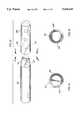
- FIG. 7is a plan view of the proximal end of the modular system shown in FIGS. 1 and 2;
- FIG. 8is a sectional view of the proximal end shown in FIG. 7, rotated 90° from the view shown in FIG. 7;
- FIG. 9is an end view of the proximal end shown as line 9--9 in FIGS. 7 and 8;
- FIG. 10is a second end view of the proximal end shown as line 10--10 in FIGS. 7 and 8;
- FIG. 11is a plan view of the distal section of the modular system shown in FIGS. 1 and 2;
- FIG. 12is an end view of the distal section shown as line 12--12 in FIG. 11;
- FIG. 13is a plan view, partially in section, of an alternative locking mechanism for the intramedullary nail system shown in FIGS. 1 and 2;
- FIGS. 14is an end view of the male portion of the alternative locking system shown as line 14--14 of FIG. 13;
- FIGS. 15is an end view of the female portion of the alternative locking system shown as line 15--15 of FIG. 13;
- FIG. 16is another alternative locking mechanism of the intramedullary nail system of the present invention.
- FIGS. 17is a end view of the alternative locking mechanism shown as line 17--17 of FIG. 16;
- FIGS. 18is a end view of the alternative locking mechanism shown as line 18--18 of FIG. 16;
- FIG. 19is a plan view partially in section, of another alternative locking mechanism in accordance with the present invention.
- FIGS. 20-22are end views of three male components for the alternative embodiment shown in FIG. 19;
- FIG. 23is an end view of the female component for the alternate embodiment shown in FIG. 19;
- FIG. 24is a plan view of another alternative locking mechanism.
- FIGS. 25-26are schematic fragmentary views of the preferred embodiment of the apparatus of the present invention illustrating the mating angular socket and projection portions thereof.
- FIGS. 1 and 2one exemplary embodiment of the modular intramedullary nail system of the present invention is shown.
- the term "modularity" for the system of the present inventionis used to describe the various sections which are used to make up an assembled nail 10 as shown in FIG. 1.
- the nail 10is formed of two or more, and preferably three discreet sections, a central section 12, a proximal section 14 to form a proximal end P and a distal section 16 to form a distal end D.
- the sectionsWhen assembled as shown in FIG. 1, the sections form a complete intramedullary nail which in accordance with known surgical procedures can be inserted into a long bone of a patient in order to stabilize a fracture.
- FIG. 2shows the system of FIG. 1 with the three components in a disassembled state.
- each of the componentsis only one of a number of different sizes and styles available to the physician so that the system shown in FIGS. 1 and 2 represent the desired or appropriate system as finally determined by the surgeon.
- the component sectionsare separate elements which are manufactured independently and need to be assembled in order to form the operative nail.
- the modularity of this productis advantageous since it permits a surgeon to select the appropriate components for a particular patient from a variety of sizes, shapes and styles, and assemble those components in order to provide a nail having the proper characteristics for the specific indications.
- the nail 10 of the present inventionhas a locking mechanism between adjacent components which is designed so that the pieces may easily be fitted together and locked to each other such that they will resist separation and rotational movement relative to each other when they are subjected to stresses after implantation.
- the central section 12has an elongated portion 18 with flutes 20 on its outer surface and a hollow opening 22 which is generally similar in shape to the outer surface (see FIG. 6).
- a socket or female connection 24is formed in both ends of the central section 12 as shown in FIGS. 3-5.
- the only difference between the two ends illustratedis that the distal end D has a smaller diameter than the proximal end P.
- the configuration of both sockets or female portions 24 of the locking mechanismsare similar. They include a tapered inner wall 26 which is conical in shape and decreases in diameter from the outer open portion of the socket inwardly.
- the tapered wall 26is adapted to mate with a tapered male connection section 28 formed on proximal section 14 or distal section 16 (see FIGS. 7, 10, 11, and 12).
- the tapered surfaces 26, 28are complementary and taper at an equal angle so that the two surfaces form a self-locking fit such as is commonly known as a Morse taper. This type of fitting is characterized by forming a tight friction-fit upon impact.
- the proximal and distal sections 14, 16may be locked into sockets 24 by simply inserting them as shown generally in FIG. 1 and then impacting the outer end of the sections in order to lock the Morse taper.
- an impact drivermay be used by the surgeon to provide the impact.
- Such an impact driveris a commercially available product which carries a tooled end portion having, for example, a commercial screw driver or wedge tip (not shown).
- One driver which has been found appropriate for medical productsis supplied by the Starrett Company, which impacts as much as 300 pounds of load when it is used.
- modular componentsare illustrated as having female tapers on the central section and cooperating male tapers on the proximal and distal sections, it is understood that any combination of cooperating male and female tapers may be used to achieve the desired connections.
- the inside diameter of the nail cannulamay be larger than the diameter of the taper.
- a "bottle bore" configurationmay be used, where the ends of nail segment are compressively swagged to a smaller diameter, that is, the outer surface of the nail segment is simultaneously and uniformly pinched so as to form a tapered diameter required for fitting together the modular components.
- the socket or female receptacleis formed with a polygonal, e.g., hexagonal opening 30 on the inner end of the tapered surface 26, which is sized and shaped to mate with a hexagonal male projection 32 formed on the outer end of the male taper 28 (see FIG. 7).
- the cooperating polygonal, e.g., hexagonal female and male sections 30, 32are closely machined so that little if any relative twisting movement takes place between the adjacent modular components after the nail 10 is implanted. Obviously, other shapes may be used for these mating components in order to prevent this twisting action from taking place.
- the cooperating angular mating componentsmay be used to align adjacent components in one or more preferred orientations, simply by rotating the components relative to each other.
- the mating angular projection and socketare asymmetrical. As illustrated in FIGS. 25 and 26, the hexagonal projection 32 and its corresponding socket 30 may be rounded at one facet 130, 132. Such asymmetry permits the cooperating ends to fit together only in a desired orientation and prevents incorrect alignment of component parts.
- the proximal endis provided with a pair of openings 34 in order to accommodate screws for holding the nail 10 relative to the bone in which it is implanted.
- the proximal section 14includes a hollow center opening 36 and a threaded female receptacle 38 for receiving a tool (not shown) for removing the nail if necessary.
- a notch 42is formed at the outer end of the distal section 14 which cooperates with a tool (not shown) for inserting the nail in the bone of the patient.
- FIGS. 11 and 12A preferred embodiment of the distal section 16 is shown in FIGS. 11 and 12 where, in addition to the tapered surface 28 and hexagonal projection 32, the outer surface includes elongated flutes 44 and an opening 46 which extends along the axis of the proximal section 16. A pair of openings 48, 50 are provided to accommodate anchoring screws.
- a pair of alignment arrows 53are formed on the outer surface of the adjacent components in order to indicate to the surgeon the proper alignment of the sections relative to each other. These arrows may be scratched, etched or otherwise marked on the outer surface of the various sections. Any type of indicia which provide for a visual or mechanical indication of the proper orientation between the adjacent sections may be used.
- FIGS. 13-15Another way to insure proper alignment is by using a design such as that shown in the embodiment of FIGS. 13-15 where adjacent nail sections 52, 54 have cooperating male and female sections in the form of a tapered outer surface 56 and a tapered inner surface 58 for providing a Morse taper fit as described above.
- the male tapered surface 56has a projection 60 formed on its outer surface which is sized and shaped to fit into a slot 62 which extends from the surface of the tapered receptacle 58.
- the cooperation between the projection 60 and slot 62provides resistance against any relative twisting between the adjacent components 52, 54 as well as to insure that the components are properly aligned when they are assembled.
- FIGS. 16-18Another embodiment of the locking mechanism is shown in FIGS. 16-18 where adjacent components 64, 66 have cooperating male and female tapers 68, 70 which lock together as discussed above. Instead of a projection 60 as shown in FIG. 13, a pair of flanges 72 are formed adjacent to the male taper 68, which fit into a pair of slots 74 formed adjacent to the female taper 70.
- FIGS. 19-23Another alternative locking mechanism is shown in FIGS. 19-23 where adjacent sections 76, 78 are provided with cooperating male and female tapers 80, 82.
- the female taper 82has a series of slots 84, 86, 88 shown in FIG. 23, which cooperate with various shapes of projections formed on the male taper 80 shown in FIGS. 20-22.
- the projections 90 shown in FIG. 20mate with the slots 88 shown in FIG. 23, the projections 92 in FIG. 21 with the slots 84 in FIG. 23 and the projections 94 in FIG. 22 with the slots 86 in FIG. 23.
- Each of the sets of projections 90, 92 and 94are different shapes and configurations so that only the projections designed to fit in a cooperating set of slots will allow insertion in those slots. This insures proper alignment between each individual component section 76 in the proper orientation without any mismatching.
- the use of the slots and projectionsalso prevent relative twisting movement between the components after they are implanted in the human body.
- FIG. 24Another embodiment for insuring rotational stability between adjacent components as shown in FIG. 24 where the adjacent components 96, 98 have cooperating male and female tapered surfaces 100, 102 which are offset at an angle ⁇ relative to the longitudinal axis of the components 96, 98, so that proper alignment and resistance against relative twisting movement are provided.
- This angled taper embodimentmay also be employed to connect modular components resulting in the axis of either or both of the proximal or distal sections 14, 16 being oriented at an angle relative to the axis of the central section 12.
Landscapes
- Health & Medical Sciences (AREA)
- Orthopedic Medicine & Surgery (AREA)
- Life Sciences & Earth Sciences (AREA)
- Surgery (AREA)
- General Health & Medical Sciences (AREA)
- Engineering & Computer Science (AREA)
- Biomedical Technology (AREA)
- Heart & Thoracic Surgery (AREA)
- Animal Behavior & Ethology (AREA)
- Public Health (AREA)
- Veterinary Medicine (AREA)
- Nuclear Medicine, Radiotherapy & Molecular Imaging (AREA)
- Medical Informatics (AREA)
- Molecular Biology (AREA)
- Neurology (AREA)
- Cardiology (AREA)
- Oral & Maxillofacial Surgery (AREA)
- Transplantation (AREA)
- Vascular Medicine (AREA)
- Surgical Instruments (AREA)
- Prostheses (AREA)
- Auxiliary Devices For And Details Of Packaging Control (AREA)
- Push-Button Switches (AREA)
- Percussion Or Vibration Massage (AREA)
- Finger-Pressure Massage (AREA)
- Massaging Devices (AREA)
Abstract
Description
1. Field of the Invention
The present invention relates to an intramedullary nail system for the repair of long bone fractures, which has a modular design for enabling a surgeon to assemble a nail or related implant during surgery which most closely fits the patient's needs.
2. Background of the Invention
Intramedullary nails have become the preferred implant treatment in many long bone fracture cases. As the use of intramedullary nails has become more popular, the design of the implants has advanced so that there are particular designs for different types of fractures. Nails having a particular configuration are desirable for certain indications. Because of wide variation of the long bones in patients, the particular style of nail is preferably available in a range of lengths, diameters, and shapes. As a result, the surgeon must have at hand a large inventory of styles and sizes to accommodate the variety of indications. Examples of such styles include, but are not limited to femoral intramedullary nail, femoral reconstruction, intramedullary hip screw, and femur components of total hips.
One solution to this variation problem is to provide a modular nail system where a surgeon can select various component parts and assemble them to fit a particular patient's needs. Such a system is taught in U.S. Pat. No. 4,805,607 to Engelhardt et al. where a modular intramedullary nail system has elongated base nails and extension members of different lengths and diameters. The base nail is the primary structural component of the system and the extension member is designed to fit on the proximal end of a base nail. By selecting various combinations of base nails and extension members, nails of a desired length and diameter can be constructed. The component parts are locked together by a pair of snap lock springs formed on the proximal end of the base nail, which include engagement tongs with locking barbs at the trailing end which are radially depressed in order to engage a counterbore on the extension member. A screw is inserted through a hole in the modular components after the rod has been implanted for preventing the tongs from disengaging.
Another intramedullary nail is disclosed in the Simpson et al. U.S. Pat. No. 5,122,141, entitled "Modular Intramedullary Nail". In the Simpson patent, an intramedullary nail system and method for providing a capability of creating intramedullary nails of any desired length includes a combination of a small number of base nail members adapted to be joined to any one of a variety of hollow extension nail members. Any selected extension nail member may be axially connected to any selected base nail member in order to prevent axially separation of the members. Additionally, each extension nail members provided with transverse openings adapted to receive a bone screw to secure the intramedullary nail within the bone to be repaired. The extension nail member is infinitely rotationally adjustable about the axis of the base nail member in order to enable the fixation of the extension member with any desired degree of anteversion prior to final assembly of the base nail member with the extension nail member.
The Comte et al. U.S. Pat. No. 4,875,475 shows a device for treating a bone that includes an intramedullary nail adapted to be driven into a hollow bone. The proximal terminal nail segment includes an internal thread and a transversely penetrating longitudinal slot adapted to receive a screw to penetrate through the nail, and to be screw connected to the bone. A distal terminal nail section comprises two transversely throughgoing bores, each adapted to receive a screw to be screw connected with the bone.
The Chapman et al. U.S. Pat. No. 4,776,330 discloses a modular femoral implant system for use in the treatment of femoral disorders resulting from injury, disease, or congenital defects. The modular system includes at least three interconnected components, including an elongated epiphyseal-metaphyseal implant, an intramedullary rod, and an angled side plate having an elongated plate portion adapted to be secured to the outer cortical wall, and a hollow sleeve adapted to extend into the femur.
A French Patent No. 1,031,128 relates to a femoral nail of multiple sections.
The Fischer U.S. Pat. No. 3,846,846 discloses a ball-shaped portion to form part of the hip joint and a second portion that extends from the ball-shaped portion into the femur. The second portion is provided with a passage through which an elongated expander rod is extended which is also to be inserted into an opening in the femur and on the expanded rod is arranged a series of expansion elements in the form of a row which as the expander rod is moved longitudinally of the row are all expanded to anchor the prosthesis to the femur.
An adjustable compression bone screw is disclosed in the Glisson U.S. Pat. No. 4,858,601 that includes a shaft having first and second sections each with an external thread that may be rotated as a unit or independently. The screw includes means adapted to receive a first driving tool for driving the shaft as unit, and further adapted to receive a second driving tool for rotating the second section independently of the first section.
The Tronzo U.S. Pat. No. 4,940,467 discloses a variable length fixation device for insertion into a hole formed in two or more bone fragments and includes a barrel portion and a fastener element. The device is used for repair of the proximal portion of a patient's femur.
The Marcus U.S. Pat. No. 4,622,959, entitled "Multi Use Femoral Intramedullary Nail" discloses an intramedullary nail for use in fractures for the left or right femur and includes a body having a head, an intermediate portion, and a distal tip. Transverse openings are provided in the body near the distal tip and in the head for receiving locking screws. One opening in the head has its axis within the femoral neck and another opening has its axis generally transverse thereto. The nail head has a seat with a transverse locating slot for securing a screw insertion tool in a fixed angular position in which the screw guide on the tool is aligned with one of the screw receiving openings.
The Brumfield U.S. Pat. No. 4,827,917, entitled "Femoral Fracture Device," provides an apparatus for treating fractures of the femur that includes a screw and an intramedullary rod. The screw has a threaded portion and a smooth portion. The rod has a head, stem, and longitudinal bore. There is at least one pair of coaxial holes through the stem, transverse to the longitudinal axis of the rod, for receiving first anchoring means such as a nail, screw, or bolt, to secure the rod within the marrow canal of the femur. There are at least a proximal pair of coaxial holes and a distal pair of coaxial holes in the head of the rod in an angled direction toward the femoral head relative to the longitudinal axis of the rod. The distal pair of head holes are adapted to slidingly receive the screw to permit the threaded portion of the screw, in use, to engage the femoral head and to allow sliding compression of a femoral neck or intertrochanteric fracture. An optional second anchoring means which will also allow sliding and compression and an optional set screw are also provided to adapt the fracture device to a variety of applications.
U.S. Pat. No. 4,995,883, issued to DeMane et al. and U.S. Pat. No. 5,108,452, issued to Thomas W. Fallin, both entitled "Modular Hip Prosthesis," disclose a modular hip prosthesis that can be custom fitted to a particular patient by a surgeon prior to surgical insertion. The prosthesis features a body having a neck portion for carrying a rounded head element, a transitional mid-section of the prosthesis body includes generally rectangular and generally rounded cross-sectional areas, and a stem section has a generally rounded cross-sectional area. The stem is tapered to receive a tubular extension sleeve with a hollowed portion corresponding in shape to the stem portion of the prosthesis. The tubular extension sleeve has an open end portion receptive of the lower tapering stem of the prosthesis body. The stem portion including an internal bore, and an attachment in the form of an elongated screw is provided for connection to the stem internal bore for securing the extension sleeve and the prosthesis body together, forming a compressive sealed connection therebetween. Pads can be attached to the transitional midsection of the prosthesis body for increasing the cross-sectional shape of the prosthesis at the transitional midsection. Removable collars can be added to the prosthesis to form a transverse load carrying interface with the upper end of the patient's femur. Frustro-conically shaped extension sleeves can be added to the prosthesis neck for extending the neck length.
U.S. Pat. No. 5,047,033, issued to Thomas W. Fallin, entitled "Mill And Guide Apparatus For Preparation Of A Hip Prosthesis," discloses a guide apparatus for preparing the femur of a patient with a rotary mill to receive a femoral hip prosthesis includes a V-shaped guide body having a lower end base portion adapted to extend into the intramedullary canal of the femur and an upper end portion comprised of at least two spaced apart struts so that the overall guide body had a configuration substantially the same as the prosthesis body sought to be implanted in the patient. The lower end of the guide body base provides one or more hemispherical receptacles for holding the hemispherical end portion of a spinning mill bit. A preferably removable transverse guide rail has connection pins at one end portion thereof for forming a connection with the upper end of the guide body at one of the struts, the arm having a curved surface that is adapted to guide the mill bit during preparation of the intramedullary canal of the patient's femur for receiving a hip prosthesis thereafter.
The inventors have determined it is advantageous to have a nail system with greater modularity than in a system such as shown in the Engelhardt patent, and one providing an easier and more secure method of attaching the components, which is assembled without utilizing a screw to hold the components together.
The present invention is directed to improved intramedullary nails providing a modular intramedullary nail system having preferably three modular components. Modular components include proximal and distal sections, and a central nail section, with each section constructed in a variety of sizes, diameters, and styles for fitting a wide range of anatomies and indications. The modular components of the present invention are quickly and easily assembled having joints of high mechanical and torsional integrity.
The modular components of the present invention preferably include a locking mechanism for connecting and locking together adjacent modular components which can quickly provide a positive locking fit that resists relative twisting or rotational movement between the components as well as translation. The locking mechanism also includes an facile alignment of components during the assembly process.
More specifically, assembly of the modular components of the present invention is achieved by one modular component having a bore with a tapered surface adapted to securely engage a cooperating tapered pin surface, with such engagement resulting in a secure connection which is resistant to rotational and translational forces. An example of a modified taper and bore providing such secure connection is a configuration known as a Morse taper. Resistance to relative rotational movement is achieved by providing a polygonal projection at the end of the taper. In the illustrated embodiment, the cooperating pin and bore are hexagonally shaped to achieve a snug fit.
In a preferred embodiment, the components are provided with an alignment mechanism to ensure the components are properly assembled. This is achieved, for example, by providing easily observed alignment indicia on the outer surfaces of the component parts, e.g., markings, indentations, tabs, flanges or keys on one component with corresponding indicia on the mating component. Asymmetric tabs, flanges or keys, and corresponding slots, may also be used to ensure the components are aligned in the proper configuration.
In an alternative embodiment, the taper or bore of one component may be adapted to accept more than one type of mated component, with each match corresponding to direct assembly of a specific implant design.
In order to acquire a better understanding of the invention, reference may be had to a detailed description of exemplary embodiments set forth below, to be considered along with the appended drawings, in which:
FIG. 1 is a plan view of a modular intramedullary designed in accordance with the present invention, in which the modular components are assembled;
FIG. 2 is a plan view of view of the modular system shown in FIG. 1, with the distal and proximal sections separated from the central section;
FIG. 3 is a plan view, partially in section, of the central section of the modular system showing in particular the female sockets at both ends;
FIG. 4 is an end view of the central section shown as line 4--4 in FIG. 3;
FIG. 5 is a second end view of the central section shown in FIG. 3;
FIG. 6 is a section view looking through a section line 6--6 of FIG. 3;
FIG. 7 is a plan view of the proximal end of the modular system shown in FIGS. 1 and 2;
FIG. 8 is a sectional view of the proximal end shown in FIG. 7, rotated 90° from the view shown in FIG. 7;
FIG. 9 is an end view of the proximal end shown asline 9--9 in FIGS. 7 and 8;
FIG. 10 is a second end view of the proximal end shown asline 10--10 in FIGS. 7 and 8;
FIG. 11 is a plan view of the distal section of the modular system shown in FIGS. 1 and 2;
FIG. 12 is an end view of the distal section shown asline 12--12 in FIG. 11;
FIG. 13 is a plan view, partially in section, of an alternative locking mechanism for the intramedullary nail system shown in FIGS. 1 and 2;
FIGS. 14 is an end view of the male portion of the alternative locking system shown asline 14--14 of FIG. 13;
FIGS. 15 is an end view of the female portion of the alternative locking system shown asline 15--15 of FIG. 13;
FIG. 16 is another alternative locking mechanism of the intramedullary nail system of the present invention;
FIGS. 17 is a end view of the alternative locking mechanism shown asline 17--17 of FIG. 16;
FIGS. 18 is a end view of the alternative locking mechanism shown asline 18--18 of FIG. 16;
FIG. 19 is a plan view partially in section, of another alternative locking mechanism in accordance with the present invention;
FIGS. 20-22 are end views of three male components for the alternative embodiment shown in FIG. 19;
FIG. 23 is an end view of the female component for the alternate embodiment shown in FIG. 19;
FIG. 24 is a plan view of another alternative locking mechanism; and
FIGS. 25-26 are schematic fragmentary views of the preferred embodiment of the apparatus of the present invention illustrating the mating angular socket and projection portions thereof.
Referring to FIGS. 1 and 2, one exemplary embodiment of the modular intramedullary nail system of the present invention is shown. The term "modularity" for the system of the present invention is used to describe the various sections which are used to make up an assemblednail 10 as shown in FIG. 1. Thenail 10 is formed of two or more, and preferably three discreet sections, acentral section 12, aproximal section 14 to form a proximal end P and adistal section 16 to form a distal end D. When assembled as shown in FIG. 1, the sections form a complete intramedullary nail which in accordance with known surgical procedures can be inserted into a long bone of a patient in order to stabilize a fracture.
FIG. 2 shows the system of FIG. 1 with the three components in a disassembled state. As may be appreciated, each of the components is only one of a number of different sizes and styles available to the physician so that the system shown in FIGS. 1 and 2 represent the desired or appropriate system as finally determined by the surgeon.
As shown in FIG. 2, the component sections are separate elements which are manufactured independently and need to be assembled in order to form the operative nail. The modularity of this product is advantageous since it permits a surgeon to select the appropriate components for a particular patient from a variety of sizes, shapes and styles, and assemble those components in order to provide a nail having the proper characteristics for the specific indications.
Thenail 10 of the present invention has a locking mechanism between adjacent components which is designed so that the pieces may easily be fitted together and locked to each other such that they will resist separation and rotational movement relative to each other when they are subjected to stresses after implantation.
As shown in greater detail in FIGS. 3-6, thecentral section 12 has an elongatedportion 18 withflutes 20 on its outer surface and ahollow opening 22 which is generally similar in shape to the outer surface (see FIG. 6).
A socket orfemale connection 24 is formed in both ends of thecentral section 12 as shown in FIGS. 3-5. The only difference between the two ends illustrated is that the distal end D has a smaller diameter than the proximal end P. The configuration of both sockets orfemale portions 24 of the locking mechanisms are similar. They include a taperedinner wall 26 which is conical in shape and decreases in diameter from the outer open portion of the socket inwardly. The taperedwall 26 is adapted to mate with a taperedmale connection section 28 formed onproximal section 14 or distal section 16 (see FIGS. 7, 10, 11, and 12). The tapered surfaces 26, 28 are complementary and taper at an equal angle so that the two surfaces form a self-locking fit such as is commonly known as a Morse taper. This type of fitting is characterized by forming a tight friction-fit upon impact.
The proximal anddistal sections sockets 24 by simply inserting them as shown generally in FIG. 1 and then impacting the outer end of the sections in order to lock the Morse taper. In the preferred embodiment, an impact driver may be used by the surgeon to provide the impact. Such an impact driver is a commercially available product which carries a tooled end portion having, for example, a commercial screw driver or wedge tip (not shown). One driver which has been found appropriate for medical products is supplied by the Starrett Company, which impacts as much as 300 pounds of load when it is used.
Although the modular components are illustrated as having female tapers on the central section and cooperating male tapers on the proximal and distal sections, it is understood that any combination of cooperating male and female tapers may be used to achieve the desired connections.
For some indications, e.g., those requiring a large diameter nail, the inside diameter of the nail cannula may be larger than the diameter of the taper. For example, a "bottle bore" configuration may be used, where the ends of nail segment are compressively swagged to a smaller diameter, that is, the outer surface of the nail segment is simultaneously and uniformly pinched so as to form a tapered diameter required for fitting together the modular components.
In order to hold the adjacent components together and to prevent them from twisting relative to each other after implantation in a human bone, the socket or female receptacle is formed with a polygonal, e.g.,hexagonal opening 30 on the inner end of the taperedsurface 26, which is sized and shaped to mate with a hexagonalmale projection 32 formed on the outer end of the male taper 28 (see FIG. 7). The cooperating polygonal, e.g., hexagonal female andmale sections nail 10 is implanted. Obviously, other shapes may be used for these mating components in order to prevent this twisting action from taking place. The cooperating angular mating components may be used to align adjacent components in one or more preferred orientations, simply by rotating the components relative to each other.
In a preferred embodiment, the mating angular projection and socket are asymmetrical. As illustrated in FIGS. 25 and 26, thehexagonal projection 32 and its correspondingsocket 30 may be rounded at onefacet
As shown in FIG. 7, the proximal end is provided with a pair ofopenings 34 in order to accommodate screws for holding thenail 10 relative to the bone in which it is implanted. As shown in FIG. 8, theproximal section 14 includes ahollow center opening 36 and a threadedfemale receptacle 38 for receiving a tool (not shown) for removing the nail if necessary. Anotch 42 is formed at the outer end of thedistal section 14 which cooperates with a tool (not shown) for inserting the nail in the bone of the patient.
A preferred embodiment of thedistal section 16 is shown in FIGS. 11 and 12 where, in addition to the taperedsurface 28 andhexagonal projection 32, the outer surface includes elongated flutes 44 and an opening 46 which extends along the axis of theproximal section 16. A pair ofopenings 48, 50 are provided to accommodate anchoring screws.
As shown in FIGS. 1 and 2, a pair ofalignment arrows 53 are formed on the outer surface of the adjacent components in order to indicate to the surgeon the proper alignment of the sections relative to each other. These arrows may be scratched, etched or otherwise marked on the outer surface of the various sections. Any type of indicia which provide for a visual or mechanical indication of the proper orientation between the adjacent sections may be used.
Another way to insure proper alignment is by using a design such as that shown in the embodiment of FIGS. 13-15 whereadjacent nail sections outer surface 56 and a taperedinner surface 58 for providing a Morse taper fit as described above. However, as shown best in FIGS. 14 and 15, the male taperedsurface 56 has aprojection 60 formed on its outer surface which is sized and shaped to fit into aslot 62 which extends from the surface of the taperedreceptacle 58. The cooperation between theprojection 60 andslot 62 provides resistance against any relative twisting between theadjacent components
Another embodiment of the locking mechanism is shown in FIGS. 16-18 whereadjacent components female tapers projection 60 as shown in FIG. 13, a pair offlanges 72 are formed adjacent to themale taper 68, which fit into a pair ofslots 74 formed adjacent to thefemale taper 70.
Another alternative locking mechanism is shown in FIGS. 19-23 whereadjacent sections female tapers female taper 82 has a series ofslots male taper 80 shown in FIGS. 20-22. For example, theprojections 90 shown in FIG. 20 mate with theslots 88 shown in FIG. 23, theprojections 92 in FIG. 21 with theslots 84 in FIG. 23 and theprojections 94 in FIG. 22 with theslots 86 in FIG. 23. Each of the sets ofprojections individual component section 76 in the proper orientation without any mismatching. The use of the slots and projections also prevent relative twisting movement between the components after they are implanted in the human body.
Another embodiment for insuring rotational stability between adjacent components as shown in FIG. 24 where theadjacent components tapered surfaces components distal sections central section 12.
The foregoing description should be considered exemplary of the invention and not restrictive. It should also be understood that improvements and modifications can be made to the invention without departing from the spirit and scope of the invention as defined in the appended claims.
Claims (10)
1. A modular intramedullary nail, comprising:
a) a proximal nail component;
b) a distal nail component;
c) a central nail component having proximal and distal end portions that are respectively connected during use to the proximal and distal nail components to define therewith upon assembly a modular intramedullary nail unit having a generally smooth continuous outer surface of generally uniform outer diameter and that is free of sharp curves, enabling the assembled nail unit to be surgically inserted into a patient's intramedullary canal;
d) connecting portions for securing the proximal and distal nail components to the respective proximal and distal end portions of the central nail component, the connecting portions including corresponding male and female conical connector sections, the conical connector sections being tapered at about the same angle so they can be fitted and secured together;
e) the connecting portions including self orienting interlocking portions on the proximal and distal nail components adjacent the conical sections for resisting relative rotational movement between the components;
f) said interlocking portions comprising at least in part a plurality of flat surfaces carried by the male conical connector section and a correspondingly shaped plurality of flat surfaces carried by the female connector section; and
wherein the central nail component is much larger than either of the proximal or distal nail components.
2. The modular nail of claim 1, further including alignment means associated with the connecting means for assuring proper alignment between the components.
3. The modular nail of claim 2, wherein the proximal and distal nail components are elongated hollow members.
4. The modular nail of claim 1, wherein the connecting portions have male and female connector sections that are generally frusto-conical in shape.
5. The modular nail of claim 1, further comprising alignment means for aligning adjacent nail sections that includes indicia formed on the outer surface of adjacent nail components.
6. The modular nail of claim 1, wherein the self-orienting interlocking portions includes at least one set of cooperating shaped projections and slots on the male and female connector sections.
7. The modular nail of claim 6, wherein at least one shaped projection and slot are formed on the conical connector sections.
8. The modular nail of claim 6, wherein at least one shaped projection and slot are formed adjacent to the conical connector sections.
9. The modular nail of claim 1, wherein the self-orienting locking portions include a shaped projection on the male connector section and a corresponding shaped socket on the female connector section, the projection and socket each being shaped to prevent relative rotational movement when they are assembled.
10. The modular nail of claim 9, wherein the shaped projection and socket are hexagonal.
Priority Applications (8)
| Application Number | Priority Date | Filing Date | Title |
|---|---|---|---|
| US08/275,806US5620445A (en) | 1994-07-15 | 1994-07-15 | Modular intramedullary nail |
| AU30996/95AAU688085B2 (en) | 1994-07-15 | 1995-07-14 | Modular intramedullary nail |
| EP95926707AEP0777447B1 (en) | 1994-07-15 | 1995-07-14 | Modular intramedullary nail |
| PCT/US1995/008917WO1996002203A1 (en) | 1994-07-15 | 1995-07-14 | Modular intramedullary nail |
| JP50519796AJP3594312B2 (en) | 1994-07-15 | 1995-07-14 | Modular intramedullary nail |
| AT95926707TATE199121T1 (en) | 1994-07-15 | 1995-07-14 | MODULAR INTRAMEDULLA NAIL |
| DE69520105TDE69520105T2 (en) | 1994-07-15 | 1995-07-14 | MODULAR INTRAMEDULLAR NAIL |
| CA002195012ACA2195012A1 (en) | 1994-07-15 | 1995-07-14 | Modular intramedullary nail |
Applications Claiming Priority (1)
| Application Number | Priority Date | Filing Date | Title |
|---|---|---|---|
| US08/275,806US5620445A (en) | 1994-07-15 | 1994-07-15 | Modular intramedullary nail |
Publications (1)
| Publication Number | Publication Date |
|---|---|
| US5620445Atrue US5620445A (en) | 1997-04-15 |
Family
ID=23053878
Family Applications (1)
| Application Number | Title | Priority Date | Filing Date |
|---|---|---|---|
| US08/275,806Expired - LifetimeUS5620445A (en) | 1994-07-15 | 1994-07-15 | Modular intramedullary nail |
Country Status (8)
| Country | Link |
|---|---|
| US (1) | US5620445A (en) |
| EP (1) | EP0777447B1 (en) |
| JP (1) | JP3594312B2 (en) |
| AT (1) | ATE199121T1 (en) |
| AU (1) | AU688085B2 (en) |
| CA (1) | CA2195012A1 (en) |
| DE (1) | DE69520105T2 (en) |
| WO (1) | WO1996002203A1 (en) |
Cited By (116)
| Publication number | Priority date | Publication date | Assignee | Title |
|---|---|---|---|---|
| US5725592A (en)* | 1996-10-29 | 1998-03-10 | Hayes Medical, Inc. | Modular prosthesis having neck component connected to stem component through cavity in body component |
| US5776194A (en)* | 1996-04-25 | 1998-07-07 | Nuvana Medical Innovations, Llc | Intermedullary rod apparatus and methods of repairing proximal humerus fractures |
| US5855579A (en)* | 1994-07-15 | 1999-01-05 | Smith & Nephew, Inc. | Cannulated modular intramedullary nail |
| WO1999005981A1 (en)* | 1996-05-06 | 1999-02-11 | Aap Implantate Ag | Intramedullary osteosynthesis nail for healing fractures or bone elongation |
| US6010505A (en)* | 1996-09-05 | 2000-01-04 | Howmedica Gmbh | Supra condylus bone nail |
| US6120504A (en)* | 1998-12-10 | 2000-09-19 | Biomet Inc. | Intramedullary nail having dual distal bore formation |
| WO2001019268A1 (en)* | 1999-09-14 | 2001-03-22 | Dietmar Wolter | Fixation system for bones |
| US6517541B1 (en)* | 1998-12-23 | 2003-02-11 | Nenad Sesic | Axial intramedullary screw for the osteosynthesis of long bones |
| US6527775B1 (en)* | 2000-09-22 | 2003-03-04 | Piper Medical, Inc. | Intramedullary interlocking fixation device for the distal radius |
| WO2003084416A1 (en)* | 2002-04-04 | 2003-10-16 | Henrik Hansson | Device at medullary nails for fixation of bone fragments at bone fractures |
| US20030204267A1 (en)* | 2002-04-30 | 2003-10-30 | Hazebrouck Stephen A. | Modular limb preservation system |
| US6652528B2 (en) | 2001-07-17 | 2003-11-25 | Biomet, Inc. | Intramedullary nail with modular sleeve |
| US20040010252A1 (en)* | 2002-03-21 | 2004-01-15 | Stryker Trauma Gmbh | Locking nail and targeting apparatus |
| US20040064145A1 (en)* | 2002-09-30 | 2004-04-01 | Ball Robert J. | Force specific impacting device |
| US6921400B2 (en) | 1999-10-21 | 2005-07-26 | Gary W. Sohngen | Modular intramedullary nail |
| US20050203510A1 (en)* | 2004-03-11 | 2005-09-15 | Sohngen Gary W. | Fixation instrument for treating a bone fracture |
| US20060015123A1 (en)* | 2004-07-15 | 2006-01-19 | Wright Medical Technology, Inc. | Guide assembly for intramedullary fixation and method of using the same |
| US20060015101A1 (en)* | 2004-07-15 | 2006-01-19 | Wright Medical Technology, Inc. | Intramedullary fixation assembly and devices and methods for installing the same |
| US20060229619A1 (en)* | 2005-03-17 | 2006-10-12 | Orbay Jorge L | Modular fracture fixation plate system with multiple metaphyseal and diaphyseal plates |
| US20060235400A1 (en)* | 2003-08-26 | 2006-10-19 | Rolf Schneider | Bone plate |
| US20070055253A1 (en)* | 2005-03-17 | 2007-03-08 | Orbay Jorge L | Modular Fracture Fixation System |
| US20070123871A1 (en)* | 2003-09-24 | 2007-05-31 | Tae-Ahn Jahng | Method and apparatus for flexible fixation of a spine |
| WO2005107619A3 (en)* | 2004-05-03 | 2007-06-07 | Lionel C Sevrain | Multi coaxial screw system |
| US7232442B2 (en) | 2005-02-22 | 2007-06-19 | Advanced Orthopaedic Solutions | Humeral nail |
| US20070173835A1 (en)* | 2006-01-13 | 2007-07-26 | Medoff Robert J | Intramedullary implant for fracture fixation and method of using the same |
| US20070186990A1 (en)* | 2006-01-27 | 2007-08-16 | Jon Serbousek | Implantable longitudinal orthopedic supports for accommodating multiple anatomical support requirements |
| US20070276380A1 (en)* | 2003-09-24 | 2007-11-29 | Tae-Ahn Jahng | Spinal stabilization device |
| US20080009873A1 (en)* | 2006-07-05 | 2008-01-10 | Advanced Orthopaedic Solutions, Inc. | Trochanteric Nail with Locking Opening |
| US20080021566A1 (en)* | 2006-07-18 | 2008-01-24 | Biomet Manufacturing Corp. | Method and apparatus for a knee implant |
| US20080269748A1 (en)* | 2007-04-24 | 2008-10-30 | Osteolign | Deformable Implant Systems and Methods |
| US20080287951A1 (en)* | 2007-03-22 | 2008-11-20 | Stoneburner James D | Segmented intramedullary structure |
| US20080308600A1 (en)* | 2007-06-14 | 2008-12-18 | Kana Richard J | Device and system for applying rotary impact |
| US20090157077A1 (en)* | 2007-12-17 | 2009-06-18 | Wright Medical Technology, Inc. | Guide assembly for intramedullary fixation and method of using the same |
| US20100076496A1 (en)* | 2004-01-26 | 2010-03-25 | Alberto Angel Fernandez | Variable Angle Locked Bone Fixation System |
| US20100094292A1 (en)* | 2008-10-14 | 2010-04-15 | Zimmer, Inc. | Modular intramedullary nail |
| US20100130978A1 (en)* | 2008-09-17 | 2010-05-27 | Skeletal Dynamics Llc | Intramedullary Arthrodesis Nail and Method of Use |
| US20100174284A1 (en)* | 2008-10-15 | 2010-07-08 | Zimmer, Gmbh | Intramedullary nail |
| US20100179551A1 (en)* | 2007-05-25 | 2010-07-15 | Zimmer, Gmbh | Reinforced intramedullary nail |
| USD625818S1 (en)* | 2009-01-02 | 2010-10-19 | Medshape Solutions, Inc. | Intramedullary medical device |
| US20110060336A1 (en)* | 2009-09-04 | 2011-03-10 | Ellipse Technologies, Inc. | Bone growth device and method |
| US20110106167A1 (en)* | 2003-09-24 | 2011-05-05 | Tae-Ahn Jahng | Adjustable spinal stabilization system |
| US20110106270A1 (en)* | 2009-10-30 | 2011-05-05 | Depuy Products, Inc. | Modular trial mechanism |
| US7998217B1 (en)* | 2005-02-02 | 2011-08-16 | Biomet Manufacturing Corp. | Modular offset stem implants |
| US20110218531A1 (en)* | 2010-03-04 | 2011-09-08 | Skeletal Dynamics Llc | Endosteal nail plate for fixing bone segments |
| US20110224671A1 (en)* | 2009-09-14 | 2011-09-15 | Kenny Koay | Variable angle compression plate |
| US8287538B2 (en) | 2008-01-14 | 2012-10-16 | Conventus Orthopaedics, Inc. | Apparatus and methods for fracture repair |
| US8328807B2 (en) | 2008-07-09 | 2012-12-11 | Icon Orthopaedic Concepts, Llc | Ankle arthrodesis nail and outrigger assembly |
| US8414584B2 (en) | 2008-07-09 | 2013-04-09 | Icon Orthopaedic Concepts, Llc | Ankle arthrodesis nail and outrigger assembly |
| US8562606B2 (en) | 2009-12-11 | 2013-10-22 | Small Bone Innovations, Inc. | Ankle fusion device, instrumentation and methods |
| US8574268B2 (en) | 2004-01-26 | 2013-11-05 | DePuy Synthes Product, LLC | Highly-versatile variable-angle bone plate system |
| US8715282B2 (en) | 2011-02-14 | 2014-05-06 | Ellipse Technologies, Inc. | System and method for altering rotational alignment of bone sections |
| US8906022B2 (en) | 2010-03-08 | 2014-12-09 | Conventus Orthopaedics, Inc. | Apparatus and methods for securing a bone implant |
| US8961518B2 (en) | 2010-01-20 | 2015-02-24 | Conventus Orthopaedics, Inc. | Apparatus and methods for bone access and cavity preparation |
| US20150320450A1 (en)* | 2014-05-12 | 2015-11-12 | DePuy Synthes Products, Inc. | Sacral fixation system |
| US9320555B2 (en) | 2013-01-31 | 2016-04-26 | Stryker European Holdings I, Llc | Modular lag screw |
| US9730739B2 (en) | 2010-01-15 | 2017-08-15 | Conventus Orthopaedics, Inc. | Rotary-rigid orthopaedic rod |
| US9788871B2 (en) | 2002-08-10 | 2017-10-17 | Howmedica Osteonics Corp. | Method and apparatus for repairing the mid-foot region via an intramedullary nail |
| US20180071105A1 (en)* | 2008-09-17 | 2018-03-15 | Skeletal Dynamics, Llc | Grooved slot allowing adjustment of the position of a bone fixation device for osteosynthesis |
| US10016220B2 (en) | 2011-11-01 | 2018-07-10 | Nuvasive Specialized Orthopedics, Inc. | Adjustable magnetic devices and methods of using same |
| US10022132B2 (en) | 2013-12-12 | 2018-07-17 | Conventus Orthopaedics, Inc. | Tissue displacement tools and methods |
| US10039661B2 (en) | 2006-10-20 | 2018-08-07 | Nuvasive Specialized Orthopedics, Inc. | Adjustable implant and method of use |
| US10064670B2 (en) | 2014-05-12 | 2018-09-04 | DePuy Synthes Products, Inc. | Sacral fixation system |
| US20190053836A1 (en)* | 2017-08-17 | 2019-02-21 | Spinal Generations, Llc | Modular femoral nail and method of use thereof |
| US10231768B2 (en) | 2003-05-30 | 2019-03-19 | DePuy Synthes Products, Inc. | Methods for implanting bone plates |
| US10238427B2 (en) | 2015-02-19 | 2019-03-26 | Nuvasive Specialized Orthopedics, Inc. | Systems and methods for vertebral adjustment |
| US10271885B2 (en) | 2014-12-26 | 2019-04-30 | Nuvasive Specialized Orthopedics, Inc. | Systems and methods for distraction |
| US10349995B2 (en) | 2007-10-30 | 2019-07-16 | Nuvasive Specialized Orthopedics, Inc. | Skeletal manipulation method |
| US20190223925A1 (en)* | 2018-01-25 | 2019-07-25 | Advanced Orthopaedic Solutions, Inc. | Bone nail |
| US10405891B2 (en) | 2010-08-09 | 2019-09-10 | Nuvasive Specialized Orthopedics, Inc. | Maintenance feature in magnetic implant |
| US10478232B2 (en) | 2009-04-29 | 2019-11-19 | Nuvasive Specialized Orthopedics, Inc. | Interspinous process device and method |
| US10517643B2 (en) | 2009-02-23 | 2019-12-31 | Nuvasive Specialized Orthopedics, Inc. | Non-invasive adjustable distraction system |
| CN110840627A (en)* | 2019-12-02 | 2020-02-28 | 北京爱康宜诚医疗器材有限公司 | hip prosthesis |
| US10617453B2 (en) | 2015-10-16 | 2020-04-14 | Nuvasive Specialized Orthopedics, Inc. | Adjustable devices for treating arthritis of the knee |
| US10624686B2 (en) | 2016-09-08 | 2020-04-21 | DePuy Synthes Products, Inc. | Variable angel bone plate |
| US10660675B2 (en) | 2010-06-30 | 2020-05-26 | Nuvasive Specialized Orthopedics, Inc. | External adjustment device for distraction device |
| WO2020129053A1 (en)* | 2018-12-18 | 2020-06-25 | Shlomoff Liraz | Systems and methods for treating periprosthetic fractures |
| US10729470B2 (en) | 2008-11-10 | 2020-08-04 | Nuvasive Specialized Orthopedics, Inc. | External adjustment device for distraction device |
| US10743794B2 (en) | 2011-10-04 | 2020-08-18 | Nuvasive Specialized Orthopedics, Inc. | Devices and methods for non-invasive implant length sensing |
| US10751094B2 (en) | 2013-10-10 | 2020-08-25 | Nuvasive Specialized Orthopedics, Inc. | Adjustable spinal implant |
| US10772665B2 (en) | 2018-03-29 | 2020-09-15 | DePuy Synthes Products, Inc. | Locking structures for affixing bone anchors to a bone plate, and related systems and methods |
| US20200306049A1 (en)* | 2017-12-15 | 2020-10-01 | Waldemar Link Gmbh & Co. Kg | Modular endoprosthesis shaft system with rotation element |
| US10820930B2 (en) | 2016-09-08 | 2020-11-03 | DePuy Synthes Products, Inc. | Variable angle bone plate |
| US10835290B2 (en) | 2015-12-10 | 2020-11-17 | Nuvasive Specialized Orthopedics, Inc. | External adjustment device for distraction device |
| US10905476B2 (en) | 2016-09-08 | 2021-02-02 | DePuy Synthes Products, Inc. | Variable angle bone plate |
| US10918425B2 (en) | 2016-01-28 | 2021-02-16 | Nuvasive Specialized Orthopedics, Inc. | System and methods for bone transport |
| US10918426B2 (en) | 2017-07-04 | 2021-02-16 | Conventus Orthopaedics, Inc. | Apparatus and methods for treatment of a bone |
| US10925651B2 (en) | 2018-12-21 | 2021-02-23 | DePuy Synthes Products, Inc. | Implant having locking holes with collection cavity for shavings |
| US11013541B2 (en) | 2018-04-30 | 2021-05-25 | DePuy Synthes Products, Inc. | Threaded locking structures for affixing bone anchors to a bone plate, and related systems and methods |
| US11026727B2 (en) | 2018-03-20 | 2021-06-08 | DePuy Synthes Products, Inc. | Bone plate with form-fitting variable-angle locking hole |
| US11191579B2 (en) | 2012-10-29 | 2021-12-07 | Nuvasive Specialized Orthopedics, Inc. | Adjustable devices for treating arthritis of the knee |
| US11202707B2 (en) | 2008-03-25 | 2021-12-21 | Nuvasive Specialized Orthopedics, Inc. | Adjustable implant system |
| US11246694B2 (en) | 2014-04-28 | 2022-02-15 | Nuvasive Specialized Orthopedics, Inc. | System for informational magnetic feedback in adjustable implants |
| US11259851B2 (en) | 2003-08-26 | 2022-03-01 | DePuy Synthes Products, Inc. | Bone plate |
| US11291484B2 (en) | 2004-01-26 | 2022-04-05 | DePuy Synthes Products, Inc. | Highly-versatile variable-angle bone plate system |
| USRE49061E1 (en) | 2012-10-18 | 2022-05-10 | Nuvasive Specialized Orthopedics, Inc. | Intramedullary implants for replacing lost bone |
| US11357549B2 (en) | 2004-07-02 | 2022-06-14 | Nuvasive Specialized Orthopedics, Inc. | Expandable rod system to treat scoliosis and method of using the same |
| US11357547B2 (en) | 2014-10-23 | 2022-06-14 | Nuvasive Specialized Orthopedics Inc. | Remotely adjustable interactive bone reshaping implant |
| US11426220B2 (en) | 2017-10-11 | 2022-08-30 | Howmedica Osteonics Corp. | Humeral fixation plate guides |
| US11446072B2 (en) | 2017-10-10 | 2022-09-20 | DePuy Synthes Products, Inc. | Self-retaining nail to insertion handle interface |
| US11577097B2 (en) | 2019-02-07 | 2023-02-14 | Nuvasive Specialized Orthopedics, Inc. | Ultrasonic communication in medical devices |
| US20230059549A1 (en)* | 2019-12-16 | 2023-02-23 | Waldemar Link Gmbh & Co. Kg | Cement retaining implant stem for permanent fixation |
| US11589901B2 (en) | 2019-02-08 | 2023-02-28 | Nuvasive Specialized Orthopedics, Inc. | External adjustment device |
| US11596419B2 (en) | 2017-03-09 | 2023-03-07 | Flower Orthopedics Corporation | Plating depth gauge and countersink instrument |
| EP4176832A1 (en)* | 2021-11-08 | 2023-05-10 | Daniel Bechtold | Intramedullary nail |
| US11696836B2 (en) | 2013-08-09 | 2023-07-11 | Nuvasive, Inc. | Lordotic expandable interbody implant |
| US11737787B1 (en) | 2021-05-27 | 2023-08-29 | Nuvasive, Inc. | Bone elongating devices and methods of use |
| US11766252B2 (en) | 2013-07-31 | 2023-09-26 | Nuvasive Specialized Orthopedics, Inc. | Noninvasively adjustable suture anchors |
| US11801187B2 (en) | 2016-02-10 | 2023-10-31 | Nuvasive Specialized Orthopedics, Inc. | Systems and methods for controlling multiple surgical variables |
| US11806054B2 (en) | 2021-02-23 | 2023-11-07 | Nuvasive Specialized Orthopedics, Inc. | Adjustable implant, system and methods |
| US11839410B2 (en) | 2012-06-15 | 2023-12-12 | Nuvasive Inc. | Magnetic implants with improved anatomical compatibility |
| US11857226B2 (en) | 2013-03-08 | 2024-01-02 | Nuvasive Specialized Orthopedics | Systems and methods for ultrasonic detection of device distraction |
| US11925389B2 (en) | 2008-10-13 | 2024-03-12 | Nuvasive Specialized Orthopedics, Inc. | Spinal distraction system |
| US12004785B2 (en) | 2022-04-21 | 2024-06-11 | DePuy Synthes Products, Inc. | Retrograde femoral intramedullary nail, and related systems and methods |
| US12023073B2 (en) | 2021-08-03 | 2024-07-02 | Nuvasive Specialized Orthopedics, Inc. | Adjustable implant |
| US12213708B2 (en) | 2020-09-08 | 2025-02-04 | Nuvasive Specialized Orthopedics, Inc. | Remote control module for adjustable implants |
| US12343050B2 (en) | 2021-08-17 | 2025-07-01 | Ps Ortho Llc | Bone fixation devices, systems, and methods |
Families Citing this family (10)
| Publication number | Priority date | Publication date | Assignee | Title |
|---|---|---|---|---|
| DE29620327U1 (en)* | 1996-11-22 | 1998-03-26 | Howmedica GmbH, 24232 Schönkirchen | Locking nail with adjustable openings for locking screws |
| FR2777772B1 (en)* | 1998-04-28 | 2000-11-03 | Depuy France | SHOULDER RECONSTRUCTION PROSTHESIS |
| US6613092B1 (en)* | 2000-07-19 | 2003-09-02 | Centerpulse Orthopedics Inc. | Stem taper adapter |
| US7854768B2 (en) | 2006-01-20 | 2010-12-21 | Zimmer Technology, Inc. | Shoulder arthroplasty system |
| CA2749684C (en)* | 2009-01-16 | 2016-04-26 | Carbofix Orthopedics Ltd. | Composite material bone implant |
| CN105877829B (en) | 2010-06-07 | 2018-06-22 | 卡波菲克斯整形有限公司 | Composite material bone implant |
| US10154867B2 (en) | 2010-06-07 | 2018-12-18 | Carbofix In Orthopedics Llc | Multi-layer composite material bone screw |
| WO2012033836A1 (en) | 2010-09-09 | 2012-03-15 | Synthes Usa, Llc | Surgical nail |
| US9526549B2 (en) | 2012-01-16 | 2016-12-27 | Carbofix Orthopedics Ltd. | Bone screw with insert |
| US10617458B2 (en) | 2015-12-23 | 2020-04-14 | Carbofix In Orthopedics Llc | Multi-layer composite material bone screw |
Citations (19)
| Publication number | Priority date | Publication date | Assignee | Title |
|---|---|---|---|---|
| FR1031128A (en)* | 1951-01-18 | 1953-06-19 | Improvements to so-called "medullary nails" osteosynthesis instruments | |
| US3846846A (en)* | 1972-09-28 | 1974-11-12 | Fischer Artur | Hip joint prosthesis |
| US4185937A (en)* | 1978-08-25 | 1980-01-29 | General Electric Company | Fastening device with positive locking means |
| US4622959A (en)* | 1985-03-05 | 1986-11-18 | Marcus Randall E | Multi-use femoral intramedullary nail |
| US4676797A (en)* | 1983-11-08 | 1987-06-30 | Mecron Medizinische Produkte Gmbh | Unit for resection prosthesis |
| US4776330A (en)* | 1986-06-23 | 1988-10-11 | Pfizer Hospital Products Group, Inc. | Modular femoral fixation system |
| US4805607A (en)* | 1987-12-03 | 1989-02-21 | Boehringer Mannheim Corporation | Modular intramedullary nail system |
| US4827917A (en)* | 1986-12-30 | 1989-05-09 | Richards Medical Company | Fermoral fracture device |
| US4858601A (en)* | 1988-05-27 | 1989-08-22 | Glisson Richard R | Adjustable compression bone screw |
| US4875475A (en)* | 1984-11-30 | 1989-10-24 | Synthes (U.S.A.) | Device for treating a bone |
| US4940467A (en)* | 1988-02-03 | 1990-07-10 | Tronzo Raymond G | Variable length fixation device |
| US4995883A (en)* | 1989-02-08 | 1991-02-26 | Smith & Nephew Richards Inc. | Modular hip prosthesis |
| US5047033A (en)* | 1989-02-08 | 1991-09-10 | Smith & Nephew Richards Inc. | Mill and guide apparatus for preparation of a hip prosthesis |
| US5062849A (en)* | 1989-03-21 | 1991-11-05 | Bristol-Myers Squibb Company | Joint for coupling two elongated prosthesis sections |
| US5108452A (en)* | 1989-02-08 | 1992-04-28 | Smith & Nephew Richards Inc. | Modular hip prosthesis |
| US5108437A (en)* | 1988-09-14 | 1992-04-28 | Pfizer Hospital Products Group, Inc. | Modular prosthesis |
| US5122141A (en)* | 1990-08-30 | 1992-06-16 | Zimmer, Inc. | Modular intramedullary nail |
| US5169259A (en)* | 1990-08-10 | 1992-12-08 | Cornell Jr Thomas W | Adjustable foot insert |
| US5352227A (en)* | 1993-02-03 | 1994-10-04 | Howmedica Inc. | Intercalary device |
Family Cites Families (4)
| Publication number | Priority date | Publication date | Assignee | Title |
|---|---|---|---|---|
| US4492226A (en)* | 1979-10-10 | 1985-01-08 | Vsesojuzny Nauchno-Issledovatelsky I Ispytatelny Institut Meditsinskoi Tekhniki | Device for uniting bone fragments |
| FR2580926B1 (en)* | 1985-04-24 | 1991-04-12 | Montagne Patrick | FEMALE PROSTHESIS WITH INDEPENDENT MODULAR COLLAR AND VARIABLE IN LENGTH AND DIRECTION FOR IMPLANTATIONS OF SINGLE FEMALE PROSTHESES OR TOTAL HIP PROSTHESES |
| CH671689A5 (en)* | 1987-05-15 | 1989-09-29 | Sulzer Ag | |
| DE3729840C1 (en)* | 1987-09-05 | 1989-02-02 | Dauerer Hermann Heinrich Micha | Medullary cavity - locking nail |
- 1994
- 1994-07-15USUS08/275,806patent/US5620445A/ennot_activeExpired - Lifetime
- 1995
- 1995-07-14ATAT95926707Tpatent/ATE199121T1/ennot_activeIP Right Cessation
- 1995-07-14JPJP50519796Apatent/JP3594312B2/ennot_activeExpired - Fee Related
- 1995-07-14DEDE69520105Tpatent/DE69520105T2/ennot_activeExpired - Lifetime
- 1995-07-14AUAU30996/95Apatent/AU688085B2/ennot_activeCeased
- 1995-07-14EPEP95926707Apatent/EP0777447B1/ennot_activeExpired - Lifetime
- 1995-07-14CACA002195012Apatent/CA2195012A1/ennot_activeAbandoned
- 1995-07-14WOPCT/US1995/008917patent/WO1996002203A1/enactiveIP Right Grant
Patent Citations (19)
| Publication number | Priority date | Publication date | Assignee | Title |
|---|---|---|---|---|
| FR1031128A (en)* | 1951-01-18 | 1953-06-19 | Improvements to so-called "medullary nails" osteosynthesis instruments | |
| US3846846A (en)* | 1972-09-28 | 1974-11-12 | Fischer Artur | Hip joint prosthesis |
| US4185937A (en)* | 1978-08-25 | 1980-01-29 | General Electric Company | Fastening device with positive locking means |
| US4676797A (en)* | 1983-11-08 | 1987-06-30 | Mecron Medizinische Produkte Gmbh | Unit for resection prosthesis |
| US4875475A (en)* | 1984-11-30 | 1989-10-24 | Synthes (U.S.A.) | Device for treating a bone |
| US4622959A (en)* | 1985-03-05 | 1986-11-18 | Marcus Randall E | Multi-use femoral intramedullary nail |
| US4776330A (en)* | 1986-06-23 | 1988-10-11 | Pfizer Hospital Products Group, Inc. | Modular femoral fixation system |
| US4827917A (en)* | 1986-12-30 | 1989-05-09 | Richards Medical Company | Fermoral fracture device |
| US4805607A (en)* | 1987-12-03 | 1989-02-21 | Boehringer Mannheim Corporation | Modular intramedullary nail system |
| US4940467A (en)* | 1988-02-03 | 1990-07-10 | Tronzo Raymond G | Variable length fixation device |
| US4858601A (en)* | 1988-05-27 | 1989-08-22 | Glisson Richard R | Adjustable compression bone screw |
| US5108437A (en)* | 1988-09-14 | 1992-04-28 | Pfizer Hospital Products Group, Inc. | Modular prosthesis |
| US4995883A (en)* | 1989-02-08 | 1991-02-26 | Smith & Nephew Richards Inc. | Modular hip prosthesis |
| US5047033A (en)* | 1989-02-08 | 1991-09-10 | Smith & Nephew Richards Inc. | Mill and guide apparatus for preparation of a hip prosthesis |
| US5108452A (en)* | 1989-02-08 | 1992-04-28 | Smith & Nephew Richards Inc. | Modular hip prosthesis |
| US5062849A (en)* | 1989-03-21 | 1991-11-05 | Bristol-Myers Squibb Company | Joint for coupling two elongated prosthesis sections |
| US5169259A (en)* | 1990-08-10 | 1992-12-08 | Cornell Jr Thomas W | Adjustable foot insert |
| US5122141A (en)* | 1990-08-30 | 1992-06-16 | Zimmer, Inc. | Modular intramedullary nail |
| US5352227A (en)* | 1993-02-03 | 1994-10-04 | Howmedica Inc. | Intercalary device |
Cited By (268)
| Publication number | Priority date | Publication date | Assignee | Title |
|---|---|---|---|---|
| US5855579A (en)* | 1994-07-15 | 1999-01-05 | Smith & Nephew, Inc. | Cannulated modular intramedullary nail |
| USRE43482E1 (en)* | 1996-04-25 | 2012-06-19 | Nuvana Medical Innovations, Llc | Intramedullary rod apparatus and methods of repairing proximal humerus fractures |
| US5776194A (en)* | 1996-04-25 | 1998-07-07 | Nuvana Medical Innovations, Llc | Intermedullary rod apparatus and methods of repairing proximal humerus fractures |
| US6322591B1 (en)* | 1996-05-06 | 2001-11-27 | Aap Implantate Ag | Intramedullary osteosynthesis nail for healing fractures or bone elongation |
| JP2001511389A (en)* | 1996-05-06 | 2001-08-14 | エイエイピー・インプランテイト・アクチエンゲゼルシャフト | Intramedullary nail system for use in fracture treatment or bone lengthening in all bones of humans and animals |
| WO1999005981A1 (en)* | 1996-05-06 | 1999-02-11 | Aap Implantate Ag | Intramedullary osteosynthesis nail for healing fractures or bone elongation |
| US6010505A (en)* | 1996-09-05 | 2000-01-04 | Howmedica Gmbh | Supra condylus bone nail |
| US5902340A (en)* | 1996-10-29 | 1999-05-11 | Hayes Medical, Inc. | Method of assembling a modular prosthesis used for bone replacement |
| US5725592A (en)* | 1996-10-29 | 1998-03-10 | Hayes Medical, Inc. | Modular prosthesis having neck component connected to stem component through cavity in body component |
| US6120504A (en)* | 1998-12-10 | 2000-09-19 | Biomet Inc. | Intramedullary nail having dual distal bore formation |
| US6517541B1 (en)* | 1998-12-23 | 2003-02-11 | Nenad Sesic | Axial intramedullary screw for the osteosynthesis of long bones |
| WO2001019268A1 (en)* | 1999-09-14 | 2001-03-22 | Dietmar Wolter | Fixation system for bones |
| US6974461B1 (en) | 1999-09-14 | 2005-12-13 | Dietmar Wolter | Fixation system for bones |
| US6926719B2 (en) | 1999-10-21 | 2005-08-09 | Gary W. Sohngen | Modular intramedullary nail |
| US6921400B2 (en) | 1999-10-21 | 2005-07-26 | Gary W. Sohngen | Modular intramedullary nail |
| US20090157080A1 (en)* | 2000-09-22 | 2009-06-18 | Piper Medical, Inc. | Intramedullary interlocking fixation devices for the distal radius |
| US8100910B2 (en) | 2000-09-22 | 2012-01-24 | Piper Medical, Inc. | Intramedullary interlocking fixation devices for the distal radius |
| US6527775B1 (en)* | 2000-09-22 | 2003-03-04 | Piper Medical, Inc. | Intramedullary interlocking fixation device for the distal radius |
| US7713271B2 (en) | 2000-09-22 | 2010-05-11 | Piper Medical, Inc. | Intramedullary interlocking fixation devices for the distal radius |
| US8092453B2 (en) | 2000-09-22 | 2012-01-10 | Piper Medical, Inc. | Intramedullary interlocking fixation devices for the distal radius |
| US7160302B2 (en) | 2000-09-22 | 2007-01-09 | Piper Medical, Inc. | Intramedullary interlocking fixation device for the distal radius |
| US20060200144A1 (en)* | 2000-09-22 | 2006-09-07 | Warburton Mark J | Intramedullary interlocking fixation devices for the distal radius |
| US6652528B2 (en) | 2001-07-17 | 2003-11-25 | Biomet, Inc. | Intramedullary nail with modular sleeve |
| US20040010252A1 (en)* | 2002-03-21 | 2004-01-15 | Stryker Trauma Gmbh | Locking nail and targeting apparatus |
| US7232443B2 (en)* | 2002-03-21 | 2007-06-19 | Stryker Trauma Gmbh | Locking nail and targeting apparatus |
| WO2003084416A1 (en)* | 2002-04-04 | 2003-10-16 | Henrik Hansson | Device at medullary nails for fixation of bone fragments at bone fractures |
| US20050182402A1 (en)* | 2002-04-04 | 2005-08-18 | Henrik Hansson | Device at medullary nails for fixation of bone fragments at bone fractures |
| US20030204267A1 (en)* | 2002-04-30 | 2003-10-30 | Hazebrouck Stephen A. | Modular limb preservation system |
| US20060041317A1 (en)* | 2002-04-30 | 2006-02-23 | Hazebrouck Stephen A | Modular orthopaedic implant system |
| US10238437B2 (en) | 2002-08-10 | 2019-03-26 | Howmedica Osteonics Corp. | Method and apparatus for repairing the mid-foot region via an intramedullary nail |
| US10925650B2 (en) | 2002-08-10 | 2021-02-23 | Howmedica Osteonics Corp. | Method and apparatus for repairing the mid-foot region via an intramedullary nail |
| US9867642B2 (en) | 2002-08-10 | 2018-01-16 | Howmedica Osteonics Corp. | Method and apparatus for repairing the mid-foot region via an intramedullary nail |
| US9788871B2 (en) | 2002-08-10 | 2017-10-17 | Howmedica Osteonics Corp. | Method and apparatus for repairing the mid-foot region via an intramedullary nail |
| US11666363B2 (en) | 2002-08-10 | 2023-06-06 | Howmedica Osteonics Corp. | Method and apparatus for repairing the mid-foot region via an intramedullary nail |
| US20040064145A1 (en)* | 2002-09-30 | 2004-04-01 | Ball Robert J. | Force specific impacting device |
| US7172598B2 (en) | 2002-09-30 | 2007-02-06 | Depuy Products, Inc. | Force specific impacting device |
| US10653466B2 (en) | 2003-05-30 | 2020-05-19 | DePuy Synthes Products, Inc. | Bone plate |
| US10231768B2 (en) | 2003-05-30 | 2019-03-19 | DePuy Synthes Products, Inc. | Methods for implanting bone plates |
| US11419647B2 (en) | 2003-05-30 | 2022-08-23 | DePuy Synthes Products, Inc. | Bone plate |
| US11259851B2 (en) | 2003-08-26 | 2022-03-01 | DePuy Synthes Products, Inc. | Bone plate |
| US8343196B2 (en) | 2003-08-26 | 2013-01-01 | Synthes Usa, Llc | Bone plate |
| US20060235400A1 (en)* | 2003-08-26 | 2006-10-19 | Rolf Schneider | Bone plate |
| US10342586B2 (en) | 2003-08-26 | 2019-07-09 | DePuy Synthes Products, Inc. | Bone plate |
| US8876873B2 (en) | 2003-08-26 | 2014-11-04 | DePuy Synthes Products, LLC | Bone plate |
| US9295505B2 (en) | 2003-08-26 | 2016-03-29 | DePuy Synthes Products, Inc. | Bone plate |
| US8852245B2 (en) | 2003-08-26 | 2014-10-07 | DePuy Synthes Products, LLC | Bone plate |
| US8845698B2 (en) | 2003-08-26 | 2014-09-30 | DePuy Synthes Products, LLC | Bone plate |
| US8979900B2 (en) | 2003-09-24 | 2015-03-17 | DePuy Synthes Products, LLC | Spinal stabilization device |
| US20110106167A1 (en)* | 2003-09-24 | 2011-05-05 | Tae-Ahn Jahng | Adjustable spinal stabilization system |
| US20070276380A1 (en)* | 2003-09-24 | 2007-11-29 | Tae-Ahn Jahng | Spinal stabilization device |
| US8968366B2 (en) | 2003-09-24 | 2015-03-03 | DePuy Synthes Products, LLC | Method and apparatus for flexible fixation of a spine |
| US20070123871A1 (en)* | 2003-09-24 | 2007-05-31 | Tae-Ahn Jahng | Method and apparatus for flexible fixation of a spine |
| US9168075B2 (en) | 2004-01-26 | 2015-10-27 | DePuy Synthes Products, Inc. | Variable angle locked bone fixation system |
| US11291484B2 (en) | 2004-01-26 | 2022-04-05 | DePuy Synthes Products, Inc. | Highly-versatile variable-angle bone plate system |
| US9314284B2 (en) | 2004-01-26 | 2016-04-19 | DePuy Synthes Products, Inc. | Highly-versatile variable-angle bone plate system |
| US20100076496A1 (en)* | 2004-01-26 | 2010-03-25 | Alberto Angel Fernandez | Variable Angle Locked Bone Fixation System |
| US10335211B2 (en) | 2004-01-26 | 2019-07-02 | DePuy Synthes Products, Inc. | Highly-versatile variable-angle bone plate system |
| US8574268B2 (en) | 2004-01-26 | 2013-11-05 | DePuy Synthes Product, LLC | Highly-versatile variable-angle bone plate system |
| US8702707B2 (en) | 2004-03-11 | 2014-04-22 | Gary W. Sohngen | Fixation instrument for treating a bone fracture |
| US8092454B2 (en) | 2004-03-11 | 2012-01-10 | Sohngen Gary W | Fixation instrument for treating a bone fracture |
| US20050203510A1 (en)* | 2004-03-11 | 2005-09-15 | Sohngen Gary W. | Fixation instrument for treating a bone fracture |
| WO2005107619A3 (en)* | 2004-05-03 | 2007-06-07 | Lionel C Sevrain | Multi coaxial screw system |
| EP1750602A4 (en)* | 2004-05-03 | 2009-01-07 | Lionel C Sevrain | Multi coaxial screw system |
| US11357549B2 (en) | 2004-07-02 | 2022-06-14 | Nuvasive Specialized Orthopedics, Inc. | Expandable rod system to treat scoliosis and method of using the same |
| US11712268B2 (en) | 2004-07-02 | 2023-08-01 | Nuvasive Specialized Orthopedics, Inc. | Expandable rod system to treat scoliosis and method of using the same |
| US20060015123A1 (en)* | 2004-07-15 | 2006-01-19 | Wright Medical Technology, Inc. | Guide assembly for intramedullary fixation and method of using the same |
| US20090157079A1 (en)* | 2004-07-15 | 2009-06-18 | Wright Medical Technology, Inc. | Intramedullary fixation assembly and devices and methods for installing the same |
| US9451971B2 (en) | 2004-07-15 | 2016-09-27 | Agilent Technologies, Inc. | Intramedullary fixation assembly and devices and methods for installing the same |
| US20090292292A1 (en)* | 2004-07-15 | 2009-11-26 | Wright Medical Technology, Inc. | Guide assembly for intramedullary fixation and method of using the same |
| US7588577B2 (en) | 2004-07-15 | 2009-09-15 | Wright Medical Technology, Inc. | Guide assembly for intramedullary fixation and method of using the same |
| US8034056B2 (en) | 2004-07-15 | 2011-10-11 | Wright Medical Technology, Inc. | Guide assembly for intramedullary fixation and method of using the same |
| US20060015101A1 (en)* | 2004-07-15 | 2006-01-19 | Wright Medical Technology, Inc. | Intramedullary fixation assembly and devices and methods for installing the same |
| US9913671B2 (en) | 2004-11-10 | 2018-03-13 | Biomet C.V. | Modular fracture fixation system |
| US9526543B2 (en) | 2004-11-10 | 2016-12-27 | Biomet C.V. | Modular fracture fixation system |
| US7998217B1 (en)* | 2005-02-02 | 2011-08-16 | Biomet Manufacturing Corp. | Modular offset stem implants |
| US7232442B2 (en) | 2005-02-22 | 2007-06-19 | Advanced Orthopaedic Solutions | Humeral nail |
| US8394098B2 (en) | 2005-03-17 | 2013-03-12 | Biomet C. V. | Modular fracture fixation plate system |
| US8394130B2 (en) | 2005-03-17 | 2013-03-12 | Biomet C.V. | Modular fracture fixation system |
| US8062296B2 (en) | 2005-03-17 | 2011-11-22 | Depuy Products, Inc. | Modular fracture fixation plate system with multiple metaphyseal and diaphyseal plates |
| US20070055253A1 (en)* | 2005-03-17 | 2007-03-08 | Orbay Jorge L | Modular Fracture Fixation System |
| US20060235404A1 (en)* | 2005-03-17 | 2006-10-19 | Orbay Jorge L | Modular fracture fixation plate system |
| US20060229619A1 (en)* | 2005-03-17 | 2006-10-12 | Orbay Jorge L | Modular fracture fixation plate system with multiple metaphyseal and diaphyseal plates |
| US20080208261A1 (en)* | 2006-01-13 | 2008-08-28 | Medoff Robert J | Method of using an intramedullary implant for fracture fixation |
| US20070173835A1 (en)* | 2006-01-13 | 2007-07-26 | Medoff Robert J | Intramedullary implant for fracture fixation and method of using the same |
| US8216238B2 (en) | 2006-01-13 | 2012-07-10 | L. G. Tellman | Method of using an intramedullary implant for fracture fixation |
| US20070186990A1 (en)* | 2006-01-27 | 2007-08-16 | Jon Serbousek | Implantable longitudinal orthopedic supports for accommodating multiple anatomical support requirements |
| US8641735B2 (en) | 2006-01-27 | 2014-02-04 | Warsaw Orthopedic, Inc. | Implantable longitudinal orthopedic supports for accommodating multiple anatomical support requirements |
| US10687869B2 (en)* | 2006-07-05 | 2020-06-23 | Advanced Orthopaedic Solutions, Inc. | Trochanteric nail with locking opening |
| US20080009873A1 (en)* | 2006-07-05 | 2008-01-10 | Advanced Orthopaedic Solutions, Inc. | Trochanteric Nail with Locking Opening |
| US12232784B2 (en) | 2006-07-05 | 2025-02-25 | Arthrex Trauma, Inc. | Trochanteric nail with locking opening |
| US7842093B2 (en) | 2006-07-18 | 2010-11-30 | Biomet Manufacturing Corp. | Method and apparatus for a knee implant |
| US20080021566A1 (en)* | 2006-07-18 | 2008-01-24 | Biomet Manufacturing Corp. | Method and apparatus for a knee implant |
| US20100137868A1 (en)* | 2006-09-28 | 2010-06-03 | Orbay Jorge L | Method of implanting a modular fracture fixation system |
| US8419775B2 (en) | 2006-09-28 | 2013-04-16 | Biomet C.V. | Method of implanting a modular fracture fixation system |
| US8747442B2 (en) | 2006-09-28 | 2014-06-10 | Biomet C.V. | Method of implanting a modular fracture fixation system |
| US10463409B2 (en) | 2006-09-28 | 2019-11-05 | Biomet C.V. | Modular fracture fixation system |
| US11234849B2 (en) | 2006-10-20 | 2022-02-01 | Nuvasive Specialized Orthopedics, Inc. | Adjustable implant and method of use |
| US10039661B2 (en) | 2006-10-20 | 2018-08-07 | Nuvasive Specialized Orthopedics, Inc. | Adjustable implant and method of use |
| US11672684B2 (en) | 2006-10-20 | 2023-06-13 | Nuvasive Specialized Orthopedics, Inc. | Adjustable implant and method of use |
| US8128627B2 (en) | 2007-03-22 | 2012-03-06 | Sonoma Orthopedic Products, Inc. | Segmented intramedullary system and apparatus |
| US20090228008A1 (en)* | 2007-03-22 | 2009-09-10 | Osteolign, Inc. | Segmented intramedullary system and apparatus |
| US8496658B2 (en) | 2007-03-22 | 2013-07-30 | Sonoma Orthopedic Products, Inc. | Segmented intramedullary structure |
| US20080287951A1 (en)* | 2007-03-22 | 2008-11-20 | Stoneburner James D | Segmented intramedullary structure |
| US20090228007A1 (en)* | 2007-03-22 | 2009-09-10 | Osteolign, Inc. | Segmented intramedullary system and methods |
| US8430879B2 (en) | 2007-03-22 | 2013-04-30 | Sonoma Orthopedic Products, Inc. | Segmented intramedullary structure |
| US8167881B2 (en) | 2007-04-24 | 2012-05-01 | Flexfix, Llc | Implantable composite apparatus and method |
| US8128626B2 (en) | 2007-04-24 | 2012-03-06 | Flexfix, Llc | System and method for delivery conformation and removal of intramedullary bone fixation devices |
| US20080269748A1 (en)* | 2007-04-24 | 2008-10-30 | Osteolign | Deformable Implant Systems and Methods |
| US8162943B2 (en) | 2007-04-24 | 2012-04-24 | Flexfix, Llc | Deformable implant systems and methods |
| US20080269750A1 (en)* | 2007-04-24 | 2008-10-30 | Osteolign | Implantable Composite Apparatus and Method |
| US8147492B2 (en) | 2007-04-24 | 2012-04-03 | Flexfix, Llc | System and method for guidance and implantation of implantable devices |
| US9421045B2 (en) | 2007-04-24 | 2016-08-23 | Flexfix, Llc | Bone stabilization device and method |
| US20080269745A1 (en)* | 2007-04-24 | 2008-10-30 | Osteolign, Inc. | Thermo-chemically activated intramedullary bone stent |
| US20080269776A1 (en)* | 2007-04-24 | 2008-10-30 | Osteolign | System and Method for Guidance and Implantation of Implantable Devices |
| US8834468B2 (en) | 2007-04-24 | 2014-09-16 | Flexfix, Llc | Bone stabilization device and method |
| US9597129B2 (en) | 2007-05-25 | 2017-03-21 | Zimmer Gmbh | Reinforced intramedullary nail |
| US20100179551A1 (en)* | 2007-05-25 | 2010-07-15 | Zimmer, Gmbh | Reinforced intramedullary nail |
| US7604640B2 (en) | 2007-06-14 | 2009-10-20 | Zimmer Spine Austin, Inc. | Device and system for applying rotary impact |
| US20080308600A1 (en)* | 2007-06-14 | 2008-12-18 | Kana Richard J | Device and system for applying rotary impact |
| US10349995B2 (en) | 2007-10-30 | 2019-07-16 | Nuvasive Specialized Orthopedics, Inc. | Skeletal manipulation method |
| US11172972B2 (en) | 2007-10-30 | 2021-11-16 | Nuvasive Specialized Orthopedics, Inc. | Skeletal manipulation method |
| US11871974B2 (en) | 2007-10-30 | 2024-01-16 | Nuvasive Specialized Orthopedics, Inc. | Skeletal manipulation method |
| US9662153B2 (en) | 2007-12-17 | 2017-05-30 | Wright Medical Technology, Inc. | Guide assembly for intramedullary fixation and method of using the same |
| US8771283B2 (en) | 2007-12-17 | 2014-07-08 | Wright Medical Technology, Inc. | Guide assembly for intramedullary fixation and method of using the same |
| US20090157077A1 (en)* | 2007-12-17 | 2009-06-18 | Wright Medical Technology, Inc. | Guide assembly for intramedullary fixation and method of using the same |
| US10603087B2 (en) | 2008-01-14 | 2020-03-31 | Conventus Orthopaedics, Inc. | Apparatus and methods for fracture repair |
| US9517093B2 (en) | 2008-01-14 | 2016-12-13 | Conventus Orthopaedics, Inc. | Apparatus and methods for fracture repair |
| US8287538B2 (en) | 2008-01-14 | 2012-10-16 | Conventus Orthopaedics, Inc. | Apparatus and methods for fracture repair |
| US11399878B2 (en) | 2008-01-14 | 2022-08-02 | Conventus Orthopaedics, Inc. | Apparatus and methods for fracture repair |
| US9788870B2 (en) | 2008-01-14 | 2017-10-17 | Conventus Orthopaedics, Inc. | Apparatus and methods for fracture repair |
| US11202707B2 (en) | 2008-03-25 | 2021-12-21 | Nuvasive Specialized Orthopedics, Inc. | Adjustable implant system |
| US12076241B2 (en) | 2008-03-25 | 2024-09-03 | Nuvasive Specialized Orthopedics, Inc. | Adjustable implant system |
| US9226783B2 (en) | 2008-07-09 | 2016-01-05 | Icon Orthopaedic Concepts, Llc | Ankle arthrodesis nail and outrigger assembly |
| US8328807B2 (en) | 2008-07-09 | 2012-12-11 | Icon Orthopaedic Concepts, Llc | Ankle arthrodesis nail and outrigger assembly |
| US8414584B2 (en) | 2008-07-09 | 2013-04-09 | Icon Orthopaedic Concepts, Llc | Ankle arthrodesis nail and outrigger assembly |
| US20150342652A1 (en)* | 2008-09-17 | 2015-12-03 | Skeletal Dynamics | Intramedullary nail and method of use |
| US20180071105A1 (en)* | 2008-09-17 | 2018-03-15 | Skeletal Dynamics, Llc | Grooved slot allowing adjustment of the position of a bone fixation device for osteosynthesis |
| US9095440B2 (en)* | 2008-09-17 | 2015-08-04 | Skeletal Dynamics, Llc | Intramedullary arthrodesis nail and method of use |
| US20100130978A1 (en)* | 2008-09-17 | 2010-05-27 | Skeletal Dynamics Llc | Intramedullary Arthrodesis Nail and Method of Use |
| US20190216611A1 (en)* | 2008-09-17 | 2019-07-18 | Skeletal Dynamics, Llc | Grooved slot allowing adjustment of the position of a bone fixation device for osteosynthesis |
| US9820862B2 (en)* | 2008-09-17 | 2017-11-21 | Skeletal Dynamics Llc | Intramedullary nail and method of use |
| US10251757B2 (en)* | 2008-09-17 | 2019-04-09 | Skeletal Dynamics Llc | Grooved slot allowing adjustment of the position of a bone fixation device for osteosynthesis |
| US11925389B2 (en) | 2008-10-13 | 2024-03-12 | Nuvasive Specialized Orthopedics, Inc. | Spinal distraction system |
| US20100094292A1 (en)* | 2008-10-14 | 2010-04-15 | Zimmer, Inc. | Modular intramedullary nail |
| WO2010045116A1 (en)* | 2008-10-14 | 2010-04-22 | Zimmer, Inc. | Modular intramedullary nail |
| US20100174284A1 (en)* | 2008-10-15 | 2010-07-08 | Zimmer, Gmbh | Intramedullary nail |
| US8668695B2 (en) | 2008-10-15 | 2014-03-11 | Zimmer Gmbh | Intramedullary nail |
| US9474557B2 (en) | 2008-10-15 | 2016-10-25 | Zimmer Gmbh | Intramedullary nail |
| US10729470B2 (en) | 2008-11-10 | 2020-08-04 | Nuvasive Specialized Orthopedics, Inc. | External adjustment device for distraction device |
| US11974782B2 (en) | 2008-11-10 | 2024-05-07 | Nuvasive Specialized Orthopedics, Inc. | External adjustment device for distraction device |
| USD625818S1 (en)* | 2009-01-02 | 2010-10-19 | Medshape Solutions, Inc. | Intramedullary medical device |
| US10517643B2 (en) | 2009-02-23 | 2019-12-31 | Nuvasive Specialized Orthopedics, Inc. | Non-invasive adjustable distraction system |
| US11918254B2 (en) | 2009-02-23 | 2024-03-05 | Nuvasive Specialized Orthopedics Inc. | Adjustable implant system |
| US11304729B2 (en) | 2009-02-23 | 2022-04-19 | Nuvasive Specialized Orthhopedics, Inc. | Non-invasive adjustable distraction system |
| US10478232B2 (en) | 2009-04-29 | 2019-11-19 | Nuvasive Specialized Orthopedics, Inc. | Interspinous process device and method |
| US11602380B2 (en) | 2009-04-29 | 2023-03-14 | Nuvasive Specialized Orthopedics, Inc. | Interspinous process device and method |
| US11207110B2 (en) | 2009-09-04 | 2021-12-28 | Nuvasive Specialized Orthopedics, Inc. | Bone growth device and method |
| US20110060336A1 (en)* | 2009-09-04 | 2011-03-10 | Ellipse Technologies, Inc. | Bone growth device and method |
| US11944358B2 (en) | 2009-09-04 | 2024-04-02 | Nuvasive Specialized Orthopedics, Inc. | Bone growth device and method |
| US8449543B2 (en) | 2009-09-04 | 2013-05-28 | Ellipse Technologies, Inc. | Bone growth device and method |
| US20110224671A1 (en)* | 2009-09-14 | 2011-09-15 | Kenny Koay | Variable angle compression plate |
| US8758346B2 (en) | 2009-09-14 | 2014-06-24 | DePuy Synthes Products, LLC | Variable angle compression plate |
| US20110106270A1 (en)* | 2009-10-30 | 2011-05-05 | Depuy Products, Inc. | Modular trial mechanism |
| US8252002B2 (en)* | 2009-10-30 | 2012-08-28 | Depuy Products, Inc. | Modular trial mechanism |
| US9308037B2 (en) | 2009-12-11 | 2016-04-12 | Stryker European Holdings I, Llc | Ankle fusion device, instrumentation and methods |
| US8562606B2 (en) | 2009-12-11 | 2013-10-22 | Small Bone Innovations, Inc. | Ankle fusion device, instrumentation and methods |
| US9730739B2 (en) | 2010-01-15 | 2017-08-15 | Conventus Orthopaedics, Inc. | Rotary-rigid orthopaedic rod |
| US9848889B2 (en) | 2010-01-20 | 2017-12-26 | Conventus Orthopaedics, Inc. | Apparatus and methods for bone access and cavity preparation |
| US8961518B2 (en) | 2010-01-20 | 2015-02-24 | Conventus Orthopaedics, Inc. | Apparatus and methods for bone access and cavity preparation |
| US8764751B2 (en)* | 2010-03-04 | 2014-07-01 | Skeletal Dynamics, Llc | Endosteal nail plate for fixing bone segments |
| US20110218531A1 (en)* | 2010-03-04 | 2011-09-08 | Skeletal Dynamics Llc | Endosteal nail plate for fixing bone segments |
| US9247971B2 (en) | 2010-03-04 | 2016-02-02 | Skeletal Dynamics, Llc | Endosteal nail plate for fixing bone segments |
| US9993277B2 (en) | 2010-03-08 | 2018-06-12 | Conventus Orthopaedics, Inc. | Apparatus and methods for securing a bone implant |
| US8906022B2 (en) | 2010-03-08 | 2014-12-09 | Conventus Orthopaedics, Inc. | Apparatus and methods for securing a bone implant |
| US10660675B2 (en) | 2010-06-30 | 2020-05-26 | Nuvasive Specialized Orthopedics, Inc. | External adjustment device for distraction device |
| US11497530B2 (en) | 2010-06-30 | 2022-11-15 | Nuvasive Specialized Orthopedics, Inc. | External adjustment device for distraction device |
| US12178477B2 (en) | 2010-06-30 | 2024-12-31 | Globus Medical Inc. | External adjustment device for distraction system |
| US10405891B2 (en) | 2010-08-09 | 2019-09-10 | Nuvasive Specialized Orthopedics, Inc. | Maintenance feature in magnetic implant |
| US8715282B2 (en) | 2011-02-14 | 2014-05-06 | Ellipse Technologies, Inc. | System and method for altering rotational alignment of bone sections |
| US9393119B2 (en) | 2011-02-14 | 2016-07-19 | Nuvasive Specialized Orthopedics, Inc. | Variable length device and method |
| US12290290B2 (en) | 2011-02-14 | 2025-05-06 | Nuvasive, Inc. | System and method for altering rotational alignment of bone sections |
| US8852187B2 (en) | 2011-02-14 | 2014-10-07 | Ellipse Technologies, Inc. | Variable length device and method |
| US11406432B2 (en) | 2011-02-14 | 2022-08-09 | Nuvasive Specialized Orthopedics, Inc. | System and method for altering rotational alignment of bone sections |
| US9393117B2 (en) | 2011-02-14 | 2016-07-19 | Nuvasive Specialized Orthopedics, Inc. | System and method for altering rotational alignment of bone sections |
| US10646262B2 (en) | 2011-02-14 | 2020-05-12 | Nuvasive Specialized Orthopedics, Inc. | System and method for altering rotational alignment of bone sections |
| US10105167B2 (en) | 2011-02-14 | 2018-10-23 | Nuvasive Specialized Orthopedics, Inc. | System and method for altering rotational alignment of bone sections |
| US10743794B2 (en) | 2011-10-04 | 2020-08-18 | Nuvasive Specialized Orthopedics, Inc. | Devices and methods for non-invasive implant length sensing |
| US11445939B2 (en) | 2011-10-04 | 2022-09-20 | Nuvasive Specialized Orthopedics, Inc. | Devices and methods for non-invasive implant length sensing |
| US10016220B2 (en) | 2011-11-01 | 2018-07-10 | Nuvasive Specialized Orthopedics, Inc. | Adjustable magnetic devices and methods of using same |
| US10349982B2 (en) | 2011-11-01 | 2019-07-16 | Nuvasive Specialized Orthopedics, Inc. | Adjustable magnetic devices and methods of using same |
| US11918255B2 (en) | 2011-11-01 | 2024-03-05 | Nuvasive Specialized Orthopedics Inc. | Adjustable magnetic devices and methods of using same |
| US11123107B2 (en) | 2011-11-01 | 2021-09-21 | Nuvasive Specialized Orthopedics, Inc. | Adjustable magnetic devices and methods of using same |
| US11839410B2 (en) | 2012-06-15 | 2023-12-12 | Nuvasive Inc. | Magnetic implants with improved anatomical compatibility |
| USRE49061E1 (en) | 2012-10-18 | 2022-05-10 | Nuvasive Specialized Orthopedics, Inc. | Intramedullary implants for replacing lost bone |
| USRE49720E1 (en) | 2012-10-18 | 2023-11-07 | Nuvasive Specialized Orthopedics, Inc. | Intramedullary implants for replacing lost bone |
| US11191579B2 (en) | 2012-10-29 | 2021-12-07 | Nuvasive Specialized Orthopedics, Inc. | Adjustable devices for treating arthritis of the knee |
| US11213330B2 (en) | 2012-10-29 | 2022-01-04 | Nuvasive Specialized Orthopedics, Inc. | Adjustable devices for treating arthritis of the knee |
| US11871971B2 (en) | 2012-10-29 | 2024-01-16 | Nuvasive Specialized Orthopedics, Inc. | Adjustable devices for treating arthritis of the knee |
| US9320555B2 (en) | 2013-01-31 | 2016-04-26 | Stryker European Holdings I, Llc | Modular lag screw |
| US11857226B2 (en) | 2013-03-08 | 2024-01-02 | Nuvasive Specialized Orthopedics | Systems and methods for ultrasonic detection of device distraction |
| US11766252B2 (en) | 2013-07-31 | 2023-09-26 | Nuvasive Specialized Orthopedics, Inc. | Noninvasively adjustable suture anchors |
| US12329374B2 (en) | 2013-07-31 | 2025-06-17 | Nuvasive Specialized Orthopedics Inc. | Noninvasively adjustable suture anchors |
| US12213893B2 (en) | 2013-08-09 | 2025-02-04 | Nuvasive, Inc. | Lordotic expandable interbody implant and method of using same |
| US11696836B2 (en) | 2013-08-09 | 2023-07-11 | Nuvasive, Inc. | Lordotic expandable interbody implant |
| US11576702B2 (en) | 2013-10-10 | 2023-02-14 | Nuvasive Specialized Orthopedics, Inc. | Adjustable spinal implant |
| US10751094B2 (en) | 2013-10-10 | 2020-08-25 | Nuvasive Specialized Orthopedics, Inc. | Adjustable spinal implant |
| US10022132B2 (en) | 2013-12-12 | 2018-07-17 | Conventus Orthopaedics, Inc. | Tissue displacement tools and methods |
| US10076342B2 (en) | 2013-12-12 | 2018-09-18 | Conventus Orthopaedics, Inc. | Tissue displacement tools and methods |
| US11246694B2 (en) | 2014-04-28 | 2022-02-15 | Nuvasive Specialized Orthopedics, Inc. | System for informational magnetic feedback in adjustable implants |
| US10064670B2 (en) | 2014-05-12 | 2018-09-04 | DePuy Synthes Products, Inc. | Sacral fixation system |
| US20150320450A1 (en)* | 2014-05-12 | 2015-11-12 | DePuy Synthes Products, Inc. | Sacral fixation system |
| US9788862B2 (en)* | 2014-05-12 | 2017-10-17 | DePuy Synthes Products, Inc. | Sacral fixation system |
| US11357547B2 (en) | 2014-10-23 | 2022-06-14 | Nuvasive Specialized Orthopedics Inc. | Remotely adjustable interactive bone reshaping implant |
| US12226127B2 (en) | 2014-10-23 | 2025-02-18 | Nuvasive Specialized Orthopedics, Inc. | Remotely adjustable interactive implantable device |
| US11963705B2 (en) | 2014-12-26 | 2024-04-23 | Nuvasive Specialized Orthopedics, Inc. | Systems and methods for distraction |
| US11439449B2 (en) | 2014-12-26 | 2022-09-13 | Nuvasive Specialized Orthopedics, Inc. | Systems and methods for distraction |
| US11890043B2 (en) | 2014-12-26 | 2024-02-06 | Nuvasive Specialized Orthopedics, Inc. | Systems and methods for distraction |
| US10271885B2 (en) | 2014-12-26 | 2019-04-30 | Nuvasive Specialized Orthopedics, Inc. | Systems and methods for distraction |
| US11612416B2 (en) | 2015-02-19 | 2023-03-28 | Nuvasive Specialized Orthopedics, Inc. | Systems and methods for vertebral adjustment |
| US12076051B2 (en) | 2015-02-19 | 2024-09-03 | Nuvasive Specialized Orthopedics, Inc. | Systems and methods for vertebral adjustment |
| US10238427B2 (en) | 2015-02-19 | 2019-03-26 | Nuvasive Specialized Orthopedics, Inc. | Systems and methods for vertebral adjustment |
| US11596456B2 (en) | 2015-10-16 | 2023-03-07 | Nuvasive Specialized Orthopedics, Inc. | Adjustable devices for treating arthritis of the knee |
| US10617453B2 (en) | 2015-10-16 | 2020-04-14 | Nuvasive Specialized Orthopedics, Inc. | Adjustable devices for treating arthritis of the knee |
| US12185982B2 (en) | 2015-12-10 | 2025-01-07 | Globus Medical Inc. | External adjustment device for distraction device |
| US10835290B2 (en) | 2015-12-10 | 2020-11-17 | Nuvasive Specialized Orthopedics, Inc. | External adjustment device for distraction device |
| US11504162B2 (en) | 2015-12-10 | 2022-11-22 | Nuvasive Specialized Orthopedics, Inc. | External adjustment device for distraction device |
| US10918425B2 (en) | 2016-01-28 | 2021-02-16 | Nuvasive Specialized Orthopedics, Inc. | System and methods for bone transport |
| US12263128B2 (en) | 2016-02-10 | 2025-04-01 | Nuvasive Specialized Orthopedics, Inc. | Systems and methods for controlling multiple surgical variables |
| US11801187B2 (en) | 2016-02-10 | 2023-10-31 | Nuvasive Specialized Orthopedics, Inc. | Systems and methods for controlling multiple surgical variables |
| US11529176B2 (en) | 2016-09-08 | 2022-12-20 | DePuy Synthes Products, Inc. | Variable angle bone plate |
| US10624686B2 (en) | 2016-09-08 | 2020-04-21 | DePuy Synthes Products, Inc. | Variable angel bone plate |
| US10820930B2 (en) | 2016-09-08 | 2020-11-03 | DePuy Synthes Products, Inc. | Variable angle bone plate |
| US10905476B2 (en) | 2016-09-08 | 2021-02-02 | DePuy Synthes Products, Inc. | Variable angle bone plate |
| US11596419B2 (en) | 2017-03-09 | 2023-03-07 | Flower Orthopedics Corporation | Plating depth gauge and countersink instrument |
| US10918426B2 (en) | 2017-07-04 | 2021-02-16 | Conventus Orthopaedics, Inc. | Apparatus and methods for treatment of a bone |
| US10667850B2 (en)* | 2017-08-17 | 2020-06-02 | Spinal Generations, Llc | Modular femoral nail and method of use thereof |
| US20200289175A1 (en)* | 2017-08-17 | 2020-09-17 | Spinal Generations, Llc | Modular femoral nail and method of use thereof |
| US20190053836A1 (en)* | 2017-08-17 | 2019-02-21 | Spinal Generations, Llc | Modular femoral nail and method of use thereof |
| US11446072B2 (en) | 2017-10-10 | 2022-09-20 | DePuy Synthes Products, Inc. | Self-retaining nail to insertion handle interface |
| US11426220B2 (en) | 2017-10-11 | 2022-08-30 | Howmedica Osteonics Corp. | Humeral fixation plate guides |
| US12137953B2 (en) | 2017-10-11 | 2024-11-12 | Howmedica Osteonics Corp. | Humeral fixation plates |
| US20200306049A1 (en)* | 2017-12-15 | 2020-10-01 | Waldemar Link Gmbh & Co. Kg | Modular endoprosthesis shaft system with rotation element |
| US12257155B2 (en) | 2017-12-15 | 2025-03-25 | Waldemar Link Gmbh & Co. Kg | Modular endoprosthesis shaft system with rotation element |
| US11654029B2 (en)* | 2017-12-15 | 2023-05-23 | Waldemar Link Gmbh & Co. Kg | Modular endoprosthesis shaft system with rotation element |
| US12076061B2 (en) | 2018-01-25 | 2024-09-03 | Arthrex Trauma, Inc. | Bone nail |
| US10932828B2 (en)* | 2018-01-25 | 2021-03-02 | Advanced Orthopaedic Solutions, Inc. | Bone nail |
| US20190223925A1 (en)* | 2018-01-25 | 2019-07-25 | Advanced Orthopaedic Solutions, Inc. | Bone nail |
| US11026727B2 (en) | 2018-03-20 | 2021-06-08 | DePuy Synthes Products, Inc. | Bone plate with form-fitting variable-angle locking hole |
| US10772665B2 (en) | 2018-03-29 | 2020-09-15 | DePuy Synthes Products, Inc. | Locking structures for affixing bone anchors to a bone plate, and related systems and methods |
| US11013541B2 (en) | 2018-04-30 | 2021-05-25 | DePuy Synthes Products, Inc. | Threaded locking structures for affixing bone anchors to a bone plate, and related systems and methods |
| US20220022926A1 (en)* | 2018-12-18 | 2022-01-27 | Liraz SHLOMOFF | Systems and methods for treating periprosthetic fractures |
| WO2020129053A1 (en)* | 2018-12-18 | 2020-06-25 | Shlomoff Liraz | Systems and methods for treating periprosthetic fractures |
| US10925651B2 (en) | 2018-12-21 | 2021-02-23 | DePuy Synthes Products, Inc. | Implant having locking holes with collection cavity for shavings |
| US11577097B2 (en) | 2019-02-07 | 2023-02-14 | Nuvasive Specialized Orthopedics, Inc. | Ultrasonic communication in medical devices |
| US12274896B2 (en) | 2019-02-07 | 2025-04-15 | Nuvasive Specialized Orthopedics, Inc. | Ultrasonic communication in medical devices |
| US11589901B2 (en) | 2019-02-08 | 2023-02-28 | Nuvasive Specialized Orthopedics, Inc. | External adjustment device |
| CN110840627A (en)* | 2019-12-02 | 2020-02-28 | 北京爱康宜诚医疗器材有限公司 | hip prosthesis |
| US20230059549A1 (en)* | 2019-12-16 | 2023-02-23 | Waldemar Link Gmbh & Co. Kg | Cement retaining implant stem for permanent fixation |
| US12213708B2 (en) | 2020-09-08 | 2025-02-04 | Nuvasive Specialized Orthopedics, Inc. | Remote control module for adjustable implants |
| US11944359B2 (en) | 2021-02-23 | 2024-04-02 | Nuvasive Specialized Orthopedics, Inc. | Adjustable implant, system and methods |
| US12004784B2 (en) | 2021-02-23 | 2024-06-11 | Nuvasive Specialized Orthopedics, Inc. | Adjustable implant, system and methods |
| US11806054B2 (en) | 2021-02-23 | 2023-11-07 | Nuvasive Specialized Orthopedics, Inc. | Adjustable implant, system and methods |
| US11737787B1 (en) | 2021-05-27 | 2023-08-29 | Nuvasive, Inc. | Bone elongating devices and methods of use |
| US12303169B1 (en) | 2021-05-27 | 2025-05-20 | Nuvasive, Inc. | Bone elongating devices and methods of use |
| US12023073B2 (en) | 2021-08-03 | 2024-07-02 | Nuvasive Specialized Orthopedics, Inc. | Adjustable implant |
| US12343050B2 (en) | 2021-08-17 | 2025-07-01 | Ps Ortho Llc | Bone fixation devices, systems, and methods |
| EP4176832A1 (en)* | 2021-11-08 | 2023-05-10 | Daniel Bechtold | Intramedullary nail |
| US12004785B2 (en) | 2022-04-21 | 2024-06-11 | DePuy Synthes Products, Inc. | Retrograde femoral intramedullary nail, and related systems and methods |
Also Published As
| Publication number | Publication date |
|---|---|
| EP0777447A4 (en) | 1997-10-01 |
| DE69520105D1 (en) | 2001-03-22 |
| JP3594312B2 (en) | 2004-11-24 |
| EP0777447A1 (en) | 1997-06-11 |
| JPH11506346A (en) | 1999-06-08 |
| AU688085B2 (en) | 1998-03-05 |
| AU3099695A (en) | 1996-02-16 |
| ATE199121T1 (en) | 2001-02-15 |
| EP0777447B1 (en) | 2001-02-14 |
| CA2195012A1 (en) | 1996-02-01 |
| WO1996002203A1 (en) | 1996-02-01 |
| DE69520105T2 (en) | 2001-06-21 |
Similar Documents
| Publication | Publication Date | Title |
|---|---|---|
| US5620445A (en) | Modular intramedullary nail | |
| US5626580A (en) | Multi-section intramedullary nail | |
| US6010506A (en) | Intramedullary nail hybrid bow | |
| US5489284A (en) | Cannulated modular intramedullary nail | |
| US5855579A (en) | Cannulated modular intramedullary nail | |
| US9687279B2 (en) | Facet joint replacement instruments and methods | |
| JP3497865B2 (en) | Multi-axis lock screw collar and plate assembly | |
| CA2494647C (en) | Modular prosthesis kits | |
| US8066779B2 (en) | Modular hip joint implant | |
| EP2670360B1 (en) | Arthroplasty plate | |
| US8632603B2 (en) | Implant positioning systems for orienting prosthesis | |
| EP2002804B1 (en) | Single entry portal implant | |
| WO2006020655A1 (en) | Method of implanting a femoral neck fixation prosthesis | |
| JP2007536944A (en) | Shoulder prosthesis using a fracture stem of the humerus | |
| JP2004535879A (en) | Bone implantation device | |
| JP6983204B2 (en) | Systems and methods for intramedullary nail implantation | |
| EP3747375A1 (en) | Systems for intramedullary nail implantation | |
| CN112165918A (en) | Hip or shoulder prosthesis and placement device thereof | |
| JP3077762B2 (en) | Modular prosthesis for the hip | |
| WO2003075801A1 (en) | Improved socket prosthesis |
Legal Events
| Date | Code | Title | Description |
|---|---|---|---|
| AS | Assignment | Owner name:SMITH & NEPHEW RICHARDS INC., TENNESSEE Free format text:ASSIGNMENT OF ASSIGNORS INTEREST;ASSIGNORS:BROSNAHAN, ROBERT;JAMES, ANTHONY;REEL/FRAME:007234/0868 Effective date:19940906 | |
| AS | Assignment | Owner name:MEMPHIS ORTHOPEDIC DESIGN, INC., TENNESSEE Free format text:ASSIGNMENT OF ASSIGNORS INTEREST;ASSIGNORS:RUSSELL, THOMAS A.;LEE, HARRY E.;REEL/FRAME:008124/0197 Effective date:19960823 | |
| STCF | Information on status: patent grant | Free format text:PATENTED CASE | |
| RF | Reissue application filed | Effective date:19990415 | |
| AS | Assignment | Owner name:SMITH & NEPHEW, INC., TENNESSEE Free format text:MERGER;ASSIGNOR:SMITH & NEPHEW RICHARDS, INC.;REEL/FRAME:010795/0088 Effective date:19961126 | |
| FPAY | Fee payment | Year of fee payment:4 | |
| FPAY | Fee payment | Year of fee payment:8 | |
| REMI | Maintenance fee reminder mailed | ||
| FPAY | Fee payment | Year of fee payment:12 |