US5620442A - Method and apparatus for external fixation of small bones - Google Patents
Method and apparatus for external fixation of small bonesDownload PDFInfo
- Publication number
- US5620442A US5620442AUS08/439,696US43969695AUS5620442AUS 5620442 AUS5620442 AUS 5620442AUS 43969695 AUS43969695 AUS 43969695AUS 5620442 AUS5620442 AUS 5620442A
- Authority
- US
- United States
- Prior art keywords
- bone
- bone screw
- securing
- receiving
- fixed relationship
- Prior art date
- Legal status (The legal status is an assumption and is not a legal conclusion. Google has not performed a legal analysis and makes no representation as to the accuracy of the status listed.)
- Expired - Lifetime
Links
- 210000000988bone and boneAnatomy0.000titleclaimsabstractdescription219
- 238000000034methodMethods0.000titledescription8
- 230000007246mechanismEffects0.000claimsdescription3
- 208000010392Bone FracturesDiseases0.000abstractdescription7
- 230000008901benefitEffects0.000description6
- 210000004872soft tissueAnatomy0.000description6
- 230000006835compressionEffects0.000description5
- 238000007906compressionMethods0.000description5
- 238000001356surgical procedureMethods0.000description3
- 210000003857wrist jointAnatomy0.000description3
- 230000000399orthopedic effectEffects0.000description2
- 230000010478bone regenerationEffects0.000description1
- 238000010276constructionMethods0.000description1
- 238000012986modificationMethods0.000description1
- 230000004048modificationEffects0.000description1
- 230000008569processEffects0.000description1
- 230000005855radiationEffects0.000description1
Images

Classifications
- A—HUMAN NECESSITIES
- A61—MEDICAL OR VETERINARY SCIENCE; HYGIENE
- A61B—DIAGNOSIS; SURGERY; IDENTIFICATION
- A61B17/00—Surgical instruments, devices or methods
- A61B17/16—Instruments for performing osteoclasis; Drills or chisels for bones; Trepans
- A61B17/17—Guides or aligning means for drills, mills, pins or wires
- A61B17/171—Guides or aligning means for drills, mills, pins or wires for external fixation
- A—HUMAN NECESSITIES
- A61—MEDICAL OR VETERINARY SCIENCE; HYGIENE
- A61B—DIAGNOSIS; SURGERY; IDENTIFICATION
- A61B17/00—Surgical instruments, devices or methods
- A61B17/16—Instruments for performing osteoclasis; Drills or chisels for bones; Trepans
- A61B17/17—Guides or aligning means for drills, mills, pins or wires
- A61B17/1739—Guides or aligning means for drills, mills, pins or wires specially adapted for particular parts of the body
- A61B17/1782—Guides or aligning means for drills, mills, pins or wires specially adapted for particular parts of the body for the hand or wrist
- A—HUMAN NECESSITIES
- A61—MEDICAL OR VETERINARY SCIENCE; HYGIENE
- A61B—DIAGNOSIS; SURGERY; IDENTIFICATION
- A61B17/00—Surgical instruments, devices or methods
- A61B17/56—Surgical instruments or methods for treatment of bones or joints; Devices specially adapted therefor
- A61B17/58—Surgical instruments or methods for treatment of bones or joints; Devices specially adapted therefor for osteosynthesis, e.g. bone plates, screws or setting implements
- A61B17/60—Surgical instruments or methods for treatment of bones or joints; Devices specially adapted therefor for osteosynthesis, e.g. bone plates, screws or setting implements for external osteosynthesis, e.g. distractors, contractors
- A61B17/64—Devices extending alongside the bones to be positioned
- A61B17/6416—Devices extending alongside the bones to be positioned with non-continuous, e.g. hinged, pin-clamp connecting element
- A—HUMAN NECESSITIES
- A61—MEDICAL OR VETERINARY SCIENCE; HYGIENE
- A61B—DIAGNOSIS; SURGERY; IDENTIFICATION
- A61B17/00—Surgical instruments, devices or methods
- A61B17/56—Surgical instruments or methods for treatment of bones or joints; Devices specially adapted therefor
- A61B17/58—Surgical instruments or methods for treatment of bones or joints; Devices specially adapted therefor for osteosynthesis, e.g. bone plates, screws or setting implements
- A61B17/88—Osteosynthesis instruments; Methods or means for implanting or extracting internal or external fixation devices
- A—HUMAN NECESSITIES
- A61—MEDICAL OR VETERINARY SCIENCE; HYGIENE
- A61B—DIAGNOSIS; SURGERY; IDENTIFICATION
- A61B17/00—Surgical instruments, devices or methods
- A61B17/56—Surgical instruments or methods for treatment of bones or joints; Devices specially adapted therefor
- A61B17/58—Surgical instruments or methods for treatment of bones or joints; Devices specially adapted therefor for osteosynthesis, e.g. bone plates, screws or setting implements
- A61B17/60—Surgical instruments or methods for treatment of bones or joints; Devices specially adapted therefor for osteosynthesis, e.g. bone plates, screws or setting implements for external osteosynthesis, e.g. distractors, contractors
- A61B17/64—Devices extending alongside the bones to be positioned
- A61B17/6425—Devices extending alongside the bones to be positioned specially adapted to be fitted across a bone joint
- A—HUMAN NECESSITIES
- A61—MEDICAL OR VETERINARY SCIENCE; HYGIENE
- A61B—DIAGNOSIS; SURGERY; IDENTIFICATION
- A61B17/00—Surgical instruments, devices or methods
- A61B17/56—Surgical instruments or methods for treatment of bones or joints; Devices specially adapted therefor
- A61B17/58—Surgical instruments or methods for treatment of bones or joints; Devices specially adapted therefor for osteosynthesis, e.g. bone plates, screws or setting implements
- A61B17/60—Surgical instruments or methods for treatment of bones or joints; Devices specially adapted therefor for osteosynthesis, e.g. bone plates, screws or setting implements for external osteosynthesis, e.g. distractors, contractors
- A61B17/66—Alignment, compression or distraction mechanisms
- A—HUMAN NECESSITIES
- A61—MEDICAL OR VETERINARY SCIENCE; HYGIENE
- A61B—DIAGNOSIS; SURGERY; IDENTIFICATION
- A61B17/00—Surgical instruments, devices or methods
- A61B2017/00831—Material properties
- A61B2017/00902—Material properties transparent or translucent
- A—HUMAN NECESSITIES
- A61—MEDICAL OR VETERINARY SCIENCE; HYGIENE
- A61B—DIAGNOSIS; SURGERY; IDENTIFICATION
- A61B17/00—Surgical instruments, devices or methods
- A61B17/56—Surgical instruments or methods for treatment of bones or joints; Devices specially adapted therefor
- A61B17/58—Surgical instruments or methods for treatment of bones or joints; Devices specially adapted therefor for osteosynthesis, e.g. bone plates, screws or setting implements
- A61B17/60—Surgical instruments or methods for treatment of bones or joints; Devices specially adapted therefor for osteosynthesis, e.g. bone plates, screws or setting implements for external osteosynthesis, e.g. distractors, contractors
- A61B2017/603—Surgical instruments or methods for treatment of bones or joints; Devices specially adapted therefor for osteosynthesis, e.g. bone plates, screws or setting implements for external osteosynthesis, e.g. distractors, contractors with three points of contact, e.g. tripod
Definitions
- the present inventionrelates generally to an orthopedic surgical procedure, and more particularly to a method and apparatus for external fixation of small bones.
- the various external fixatorsare known for the fixation of small bones during a surgical procedure.
- one particular type of fixator sold by Orthofix S.r.l. for small boneshas two bone screw clamps with a barbell-shaped connector disposed between the bone screw clamps.
- the barbell-shaped connectoris captured by a bushing and an apertured nut which is able to screw on to the end of each of the bone screw clamps.
- a camis used to force the bushing in a direction so as to cause the bushing to force the rounded end of the barbell-shaped connector against the apertured nut to secure the position of the barbell-shaped connector with respect to the bone screw clamp.
- the bone screw clampincludes a body which is able to slide on the arm of the bone screw clamp and has a cover with a plurality of circular grooves disposed thereon. The circular grooves are used to receive a plurality of bone screws.
- fixators of the type described aboveare effective in fixating bones, they nevertheless can be the subject of certain improvements.
- the barbell-shaped nature of the interconnection between the bone screw clampslimits the ability of the physician to view the fracture in that the barbell connector is not radiolucent.
- the bone screw clampswould only provide two point fixation of the bone screws.
- the inventionrelates to a fixator operable for securing two portions of bone in a fixed relationship to each other, with the first bone portion having a first bone screw attached thereto while the second bone portion has a second bone screw attached thereto.
- the fixatorincludes first means for receiving the first bone screw which has a spherical portion.
- the fixatorincludes a second means for receiving a second bone screw which also has a spherical portion.
- the fixatorfurther includes means for securing the first means for receiving a first bone screw to the second means for receiving the second bone screw.
- the means for securinginclude a connection member which is operable to form a radiographic window to permit radiographic examination of the fracture, as well as a cantilever member operable to secure the spherical portion of said first means for receiving the first bone screw to the connection member.
- An advantage of the present inventionis to provide a method and apparatus for fixation of small bones that more rigidly secures movement of a bone screw clamp with respect to the body of the fixator.
- Another advantage of the present inventionis to provide a method and apparatus for fixation of small bones which permits radiographic examination of the fracture site.
- Another advantage of the present inventionis to provide a method and apparatus for fixation of small bones in which the bone screw clamp is able to provide three point fixation of bone screws.
- a related advantage of the present inventionis to provide a method and apparatus for securing small bones in which the bone screw clamp is positioned with respect to the body of the fixator by means of a cantilever member.
- Another advantage of the present inventionis the provision of a method and apparatus for the fixation of small bones having a cam which generates a relatively large amount of locking force to secure the angular position of the bone screw clamp.
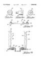
- FIG. 1is an illustration of the apparatus for fixation of small bones in operative association with a wrist joint according to the teachings of the preferred embodiment of the present invention
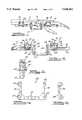
- FIG. 2is an elevational view of the apparatus for fixation of small bones shown in FIG. 1 according to the teachings of the preferred embodiment of the present invention
- FIG. 3is a side elevational view of the apparatus for fixation of small bones shown in FIG. 2 according to the teachings of the preferred embodiment of the present invention
- FIG. 4is an elevational view of the cantilever member of the apparatus for fixation of small bones shown in FIG. 2 according to the teachings of the preferred embodiment of the present invention
- FIG. 5is an elevational view of the locking member used in association with the apparatus for fixation of small bones shown in FIG. 2 according to the teachings of the preferred embodiment of the present invention
- FIG. 6(a)-(c)are elevational views of the locking cam used in conjunction with the apparatus for fixation of small bones shown in FIG. 2 according to the teachings of the preferred embodiment of the present invention
- FIG. 7is an elevational view of the compression/distraction mechanism of the apparatus for fixation of small bones shown in FIG. 2 according to the teachings of the preferred embodiment of the present invention
- FIG. 8is an illustration of the apparatus for fixation of small bones shown in operative association with a set of forceps used to locate the apparatus according to the teachings of the preferred embodiment of the present invention
- FIGS. 9(a)-9(b)are illustrations of a drill guide used to locate holes for receiving bone pins which are used with the apparatus for fixation of bones according to the teachings of the preferred embodiment of the present invention.
- FIG. 10is an illustration of the apparatus for fixation of small bones according to the second preferred embodiment of the present invention.
- an apparatus 10 for fixation of small bone portions 12 and 14is shown.
- the apparatus 10is illustrated as being used to secure a bone fracture 16 which is located in close proximity to the wrist joint.
- the apparatus 10is used to secure the bone portions 12 and 14 in a fixed relationship so as to permit the fractured portions to fuse properly. While the apparatus 10 is shown in conjunction with a wrist joint, it will be appreciated that the apparatus 10 may be used with other joints as well.
- the apparatus 10includes a first clamp support arm 18 and a second clamp support arm 20.
- the first and second clamp support arms 18 and 20are connected to each other by means of a connection member 22 as will be more fully discussed below.
- the first clamp support arm 18includes an extension portion 24 and a spherical portion 26.
- the extension portion 24 of the first clamp support arm 18is used to allow a first bone screw clamp 28 to slide thereon as described below.
- the spherical projection 26extends from the extension portion 24 and is used to engage the connection member 22.
- the second clamp support arm 20also includes an extension portion 30 and a spherical portion 32.
- the extension portion 30is used to allow a second bone screw clamp 34 to slide thereon, while the spherical projection 32 extends from the extension portion 30 and serves to allow engagement with the connection member 22.
- the first and second bone screw support clamps 28 and 34are operable to slide on the first extension portion 24 and the second extension portion 30, respectively, and are operable to support a plurality of bone screws 36 after they have been secured to bone.
- the bone screw clamps 28 and 34include a plurality of bone screw rests 38.
- the bone screw rests 38contain a V-shaped groove which is operable to engage the sides of the bone screws 36.
- the bone screw rests 38are secured to the bodies 40 and 42 of the bone screw clamps 28 and 34 by staking a projection extending from the bottom of the bone screw rests 38.
- the staking operationis performed such as to allow approximately 0.002" difference between the length of the projection and the depth of the bore receiving the projection in the bodies 40 and 42 so as to allow limited movement of the bone screw rests 38.
- This limited movement of the bone screw rests 38allows the bone screw rests 38 to center on the bone screws 36 and therefore not cause the bone screws 36 to otherwise stress the bone when the bone screws are not precisely aligned with the groove of the bone screw rests 38.
- the bone screw clamps 28 and 34further each include cover members 46 and 48 which are able to be inserted over the bone screws 36 when the bone screws 36 are located in the bone screw rests 38.
- the cover members 46 and 48each include an aperture 50 which allows a threaded fastener 52 to pass through the cover members 46 and 48 and into a threaded aperture of the bodies 40 and 42 of the bone screw clamps 28 and 34.
- the apparatusfurther includes a plurality of locking screws 54.
- the locking screws 54are operable to threadably engage the bodies 40 and 42 of the bone screw clamps 28 and 34 and extend therethrough to engage the extension portions 24 and 30 of the first and second clamp support arms 18 and 20, respectively. Accordingly, upon rotation of the locking screws 54, the locking screws 54 are able to engage the extension portions 24 and 30 of the first and second clamp support arms 18 and 20 so as to prevent longitudinal movement of the bone support clamps 28 and 34.
- connection member 22 and the cantilever member 56will now be described with reference to FIGS. 4 and 5.
- the connection member 22is generally U-shaped so as to form a radiographic window 58 through which the fracture 16 may be viewed.
- the connection member 22includes a first plurality of apertures 60 as well as a second plurality of apertures 62.
- the first plurality of apertures 60are operable to receive a locking pin 64 which extends through the cantilever members 62 as well as the connection member 22 so as to form a hinge between the connection member 22 and the cantilever members 62.
- the second plurality of apertures 62are used to receive a locking cam 66 which also extends through the apertures of the cantilever members 56.
- the locking cam 66(shown in FIG.
- the locking cam 66is able to generate greater force for securing the cantilever member 56 to the connection member 22 for a given applied torque.
- connection member 22also has a plurality of central apertures 70 which are able to receive the spherical portions 26 and 32 of the first and second clamp support arms 18 and 20 while each of the cantilever members 56 also includes a central aperture 72 which is able to receive part of the spherical portions 26 and 32 of the first and second clamp support arms 18 and 20. Accordingly, when the locking cam 66 is rotated in such a manner so as to displace the cantilever member 56 in a direction towards the connection member 22, the spherical portions 26 and 32 of each of the clamp support arms 18 and 20 are securely engaged between the connection member 22 and the cantilever members 56.
- the first clamp support member 28further includes a compression/distraction assembly 74 as shown in FIG. 7.
- the compression/distraction assembly 74includes a threaded pin 76 having a head 78 with a hex-shaped recess.
- the threaded pin 76is secured to the first clamp support arm 28 by means of a first mounting member 80 and a second mounting member 82, each of which is attached by means of a threaded fastener 84.
- the compression/distraction assembly 74further includes a movable member 86 which threadably engages the threaded pin 76 of the compression/distraction assembly 74.
- the movable member 86includes a pin 88 which engages a recess in the body 40 of the first bone screw clamp 28. As will be appreciated by those skilled in the art, rotation of the threaded pin 76 causes the movable member 86 to be displaced with respect to the first and second mounting members 80 and 82. Because the pin 88 of the movable member 86 engages the bone screw clamp 28, the bone screw clamp 28 is also able to move upon rotation of the threaded pin 76.
- the apparatus 10may also be used with a plurality of forceps 90 shown in FIG. 8.
- the forceps 90include a handle 92 which has a bone screw engaging portion and a rotatable knob 96.
- the rotatable knob 96is secured to a threaded member 98 which extends to the bone screw engaging portion 94. Accordingly, by rotation of the knob 96, the bone screw engagement portion 94 can clamp the bone screws 36 in a secure manner.
- the forceps 90are used, the bone screws 36 are initially clamped by the forceps 90 and then the forceps 90 are used to manipulate the position of the apparatus 10.
- the cams 66are rotated so as to secure the spherical portions 26 and 32 of the clamp support arms 18 and 20 to the connection member 22 and the threaded fasteners 54 are rotated so as to secure the position of the bone screw clamps 28 and 34 with respect to the clamp support arms 18 and 20.
- the drill guide 100includes a guide portion 102 having two longitudinal bores 104 extending therethrough.
- the drill guide 100also includes a handle portion 106 which may be used to position the guide portion 102.
- the guide portion 102 of the drill guide 100is positioned such that the circular projections 106 of the guide portion 102 are received through a soft tissue sleeve (not shown) which engages the bone screw rests 38 of the bone screw clamps 28 and 34.
- a drillis then used to form a hole in the bone and then the drill and the drill guide 100 are removed.
- a bone screw 36is then inserted into the soft tissue sleeve and then is secured to the bone.
- the soft tissue sleeveis then removed and then the bone screw is secured to the bone screw clamp 28 by rotation of the threaded fastener.
- the apparatus 10 of the second embodiment of the present inventionincludes a first clamp support arm 18 and a second clamp support arm 20.
- a first bone screw clamp 28is located on the first clamp support arm 18, while a second bone screw clamp 34 is located on the second clamp support arm 20.
- the first and second clamp support arms 18 and 20are connected by a connection member 22 which is operable to locate the first clamp support arm 18 at a position which is below and at right angles to the second bone support arm 20. This allows the apparatus to be used in other forms of fixation of small bones.
- the apparatus 10is initially oriented in the position where it is desired to be ultimately secured to the bone.
- a soft tissue sleeve(not shown), followed by the drill guide 100, is inserted into the first bone screw support clamp 28 and onto the bone screw rest 38 of the bone screw clamp 28.
- a drillis then used to form two holes in the bone and then the drill guide 100 is removed from the first bone screw clamp 28.
- Two bone screws 36are then inserted into the soft tissue sleeve and are rotated so as to securely engage the bone.
- the soft tissue sleeveis then removed from the bone screw clamp 28 and then the cover member 46 is secured to the body 40 of the bone screw clamp 28. This process is then repeated with respect to the bone screws 36 which are inserted into the second bone screw clamp 34.
Landscapes
- Health & Medical Sciences (AREA)
- Life Sciences & Earth Sciences (AREA)
- Orthopedic Medicine & Surgery (AREA)
- Surgery (AREA)
- Medical Informatics (AREA)
- Engineering & Computer Science (AREA)
- Biomedical Technology (AREA)
- Heart & Thoracic Surgery (AREA)
- Nuclear Medicine, Radiotherapy & Molecular Imaging (AREA)
- Molecular Biology (AREA)
- Animal Behavior & Ethology (AREA)
- General Health & Medical Sciences (AREA)
- Public Health (AREA)
- Veterinary Medicine (AREA)
- Dentistry (AREA)
- Oral & Maxillofacial Surgery (AREA)
- Surgical Instruments (AREA)
Abstract
Description
Claims (20)
Priority Applications (9)
| Application Number | Priority Date | Filing Date | Title |
|---|---|---|---|
| US08/439,696US5620442A (en) | 1995-05-12 | 1995-05-12 | Method and apparatus for external fixation of small bones |
| US08/647,096US5743898A (en) | 1995-05-12 | 1996-05-09 | Method and apparatus for external fixation of small bones |
| AU59195/96AAU5919596A (en) | 1995-05-12 | 1996-05-10 | Method and apparatus for external fixation of small bones |
| DE69631247TDE69631247D1 (en) | 1995-05-12 | 1996-05-10 | METHOD AND DEVICE FOR EXTERNAL FIXATION OF SMALL BONES |
| PCT/US1996/006679WO1996035385A1 (en) | 1995-05-12 | 1996-05-10 | Method and apparatus for external fixation of small bones |
| HK98110582.6AHK1009735B (en) | 1995-05-12 | 1996-05-10 | Method and apparatus for external fixation of small bones |
| EP96916452AEP0835079B1 (en) | 1995-05-12 | 1996-05-10 | Method and apparatus for external fixation of small bones |
| AT96916452TATE256994T1 (en) | 1995-05-12 | 1996-05-10 | METHOD AND DEVICE FOR EXTERNAL FIXATION OF SMALL BONE |
| JP53428496AJP3669707B2 (en) | 1995-05-12 | 1996-05-10 | Device for external fixation of small bones |
Applications Claiming Priority (1)
| Application Number | Priority Date | Filing Date | Title |
|---|---|---|---|
| US08/439,696US5620442A (en) | 1995-05-12 | 1995-05-12 | Method and apparatus for external fixation of small bones |
Related Child Applications (1)
| Application Number | Title | Priority Date | Filing Date |
|---|---|---|---|
| US08/647,096Continuation-In-PartUS5743898A (en) | 1995-05-12 | 1996-05-09 | Method and apparatus for external fixation of small bones |
Publications (1)
| Publication Number | Publication Date |
|---|---|
| US5620442Atrue US5620442A (en) | 1997-04-15 |
Family
ID=23745775
Family Applications (1)
| Application Number | Title | Priority Date | Filing Date |
|---|---|---|---|
| US08/439,696Expired - LifetimeUS5620442A (en) | 1995-05-12 | 1995-05-12 | Method and apparatus for external fixation of small bones |
Country Status (1)
| Country | Link |
|---|---|
| US (1) | US5620442A (en) |
Cited By (68)
| Publication number | Priority date | Publication date | Assignee | Title |
|---|---|---|---|---|
| WO1999030626A1 (en)* | 1997-12-15 | 1999-06-24 | Electro-Biology, Inc. | Method and apparatus for external fixation of small bones |
| US5931837A (en)* | 1997-12-09 | 1999-08-03 | University Of Iowa Research Foundation | Method and apparatus for external fixation of an ankle |
| US5941879A (en)* | 1997-11-18 | 1999-08-24 | Electro-Biology, Inc. | Method and apparatus for external fixation of bones |
| US5976136A (en)* | 1998-05-11 | 1999-11-02 | Electro Biology, Inc. | Method and apparatus for external bone fixator |
| US6056748A (en)* | 1998-02-20 | 2000-05-02 | Weiner; Lon S. | Modular fixator assembly |
| US6152925A (en)* | 1998-03-04 | 2000-11-28 | University Of Iowa Research Foundation | Method and apparatus for external fixation of an elbow |
| US6162223A (en)* | 1999-04-09 | 2000-12-19 | Smith & Nephew, Inc. | Dynamic wrist fixation apparatus for early joint motion in distal radius fractures |
| US6162222A (en)* | 1998-11-11 | 2000-12-19 | Electro Biology, Inc. | Method and apparatus for external fixation of the pelvis |
| US6171308B1 (en)* | 1995-05-12 | 2001-01-09 | Kirk Jay Bailey | Method and apparatus for external fixation of large bones |
| US20030069580A1 (en)* | 2001-10-09 | 2003-04-10 | Langmaid Michael N. | Adjustable fixator |
| WO2003068082A1 (en) | 1999-10-21 | 2003-08-21 | Ebi, L.P. | Clamp assembly for an external fixation system |
| US6652524B1 (en) | 2002-05-30 | 2003-11-25 | Millennium Medical Technologies, Inc. | Fixator with outrigger |
| US6709433B1 (en) | 2001-12-20 | 2004-03-23 | Biomet, Inc. | Bridging/non-bridging external bone fixator |
| US6746448B2 (en) | 2002-05-30 | 2004-06-08 | Millennium Medical Technologies, Inc. | Outrigger for bone fixator |
| US20040181221A1 (en)* | 2003-03-12 | 2004-09-16 | Huebner Randall J. | External fixator |
| US20040249375A1 (en)* | 2003-06-03 | 2004-12-09 | The John M. Agee Trust | External fixator for colles' fracture |
| WO2005092220A1 (en)* | 2004-03-10 | 2005-10-06 | Synthes Gmbh | External fixer for osteosynthesis |
| US20060229604A1 (en)* | 2005-03-18 | 2006-10-12 | Olsen Ron A | Adjustable splint for osteosynthesis with modular components |
| US20060229605A1 (en)* | 2005-03-18 | 2006-10-12 | Olsen Ron A | Adjustable splint for osteosynthesis with incrementing assembly for adjustment in predetermined increments |
| US20070162028A1 (en)* | 2005-12-09 | 2007-07-12 | Jesse Jackson | Cannulated screw |
| US20080021451A1 (en)* | 2006-04-20 | 2008-01-24 | Millennium Medical Technologies, Inc. | External Fixator |
| US9155561B2 (en) | 2013-03-06 | 2015-10-13 | Stryker Trauma Sa | Mini-rail external fixator |
| US20160015426A1 (en)* | 2014-07-15 | 2016-01-21 | Treace Medical Concepts, Inc. | Bone positioning and cutting system and method |
| US20160022315A1 (en)* | 2013-01-21 | 2016-01-28 | Tecres S.P.A. | External fixing device, for treating bone fractures |
| US9339296B2 (en) | 2014-06-19 | 2016-05-17 | Biomet Manufacturing, Llc | Joint distraction system |
| CN108324358A (en)* | 2018-01-19 | 2018-07-27 | 上海联影医疗科技有限公司 | Fracture fixation equipment and reduction of the fracture system |
| US10045807B2 (en) | 2015-08-14 | 2018-08-14 | Treace Medical Concepts, Inc. | Bone positioning and preparing guide systems and methods |
| US10342590B2 (en) | 2015-08-14 | 2019-07-09 | Treace Medical Concepts, Inc. | Tarsal-metatarsal joint procedure utilizing fulcrum |
| WO2019141262A1 (en)* | 2018-01-19 | 2019-07-25 | Shenzhen United Imaging Healthcare Co., Ltd. | Bone fracture reduction device and system |
| US10512470B1 (en) | 2016-08-26 | 2019-12-24 | Treace Medical Concepts, Inc. | Osteotomy procedure for correcting bone misalignment |
| US10524808B1 (en) | 2016-11-11 | 2020-01-07 | Treace Medical Concepts, Inc. | Devices and techniques for performing an osteotomy procedure on a first metatarsal to correct a bone misalignment |
| US10531896B2 (en) | 2015-08-10 | 2020-01-14 | Stryker European Holdings I, Llc | Distraction tube with wire clamp |
| US10561426B1 (en) | 2015-01-07 | 2020-02-18 | Treace Medical Concepts, Inc. | Bone cutting guide systems and methods |
| US10575862B2 (en) | 2015-09-18 | 2020-03-03 | Treace Medical Concepts, Inc. | Joint spacer systems and methods |
| US10653467B2 (en) | 2015-05-06 | 2020-05-19 | Treace Medical Concepts, Inc. | Intra-osseous plate system and method |
| US10849663B2 (en) | 2015-07-14 | 2020-12-01 | Treace Medical Concepts, Inc. | Bone cutting guide systems and methods |
| US10849631B2 (en) | 2015-02-18 | 2020-12-01 | Treace Medical Concepts, Inc. | Pivotable bone cutting guide useful for bone realignment and compression techniques |
| US10874446B2 (en) | 2015-07-14 | 2020-12-29 | Treace Medical Concepts, Inc. | Bone positioning guide |
| US10939939B1 (en) | 2017-02-26 | 2021-03-09 | Treace Medical Concepts, Inc. | Fulcrum for tarsal-metatarsal joint procedure |
| US11278337B2 (en) | 2015-08-14 | 2022-03-22 | Treace Medical Concepts, Inc. | Tarsal-metatarsal joint procedure utilizing fulcrum |
| US11583323B2 (en) | 2018-07-12 | 2023-02-21 | Treace Medical Concepts, Inc. | Multi-diameter bone pin for installing and aligning bone fixation plate while minimizing bone damage |
| US11596443B2 (en) | 2018-07-11 | 2023-03-07 | Treace Medical Concepts, Inc. | Compressor-distractor for angularly realigning bone portions |
| US11607250B2 (en) | 2019-02-13 | 2023-03-21 | Treace Medical Concepts, Inc. | Tarsal-metatarsal joint procedure utilizing compressor-distractor and instrument providing sliding surface |
| US11622797B2 (en) | 2020-01-31 | 2023-04-11 | Treace Medical Concepts, Inc. | Metatarsophalangeal joint preparation and metatarsal realignment for fusion |
| US11627954B2 (en) | 2019-08-07 | 2023-04-18 | Treace Medical Concepts, Inc. | Bi-planar instrument for bone cutting and joint realignment procedure |
| US11653951B2 (en)* | 2018-11-06 | 2023-05-23 | Ali Moradi | External orthopedic fixation device |
| USD1011524S1 (en) | 2022-02-23 | 2024-01-16 | Treace Medical Concepts, Inc. | Compressor-distractor for the foot |
| US11889998B1 (en) | 2019-09-12 | 2024-02-06 | Treace Medical Concepts, Inc. | Surgical pin positioning lock |
| US11890039B1 (en) | 2019-09-13 | 2024-02-06 | Treace Medical Concepts, Inc. | Multi-diameter K-wire for orthopedic applications |
| US11931106B2 (en) | 2019-09-13 | 2024-03-19 | Treace Medical Concepts, Inc. | Patient-specific surgical methods and instrumentation |
| US11986251B2 (en) | 2019-09-13 | 2024-05-21 | Treace Medical Concepts, Inc. | Patient-specific osteotomy instrumentation |
| US12004789B2 (en) | 2020-05-19 | 2024-06-11 | Treace Medical Concepts, Inc. | Devices and techniques for treating metatarsus adductus |
| US20240366267A1 (en)* | 2022-01-14 | 2024-11-07 | Chip Shot Partner LLC | External Fixator Apparatus & Method |
| USD1051382S1 (en) | 2022-02-23 | 2024-11-12 | Treace Medical Concepts, Inc. | Lesser metatarsal cut guide |
| US12161371B2 (en) | 2021-01-18 | 2024-12-10 | Treace Medical Concepts, Inc. | Contoured bone plate with locking screw for bone compression, particularly across a tarsometatarsal joint |
| USD1057155S1 (en) | 2022-02-23 | 2025-01-07 | Treace Medical Concepts, Inc. | Lesser metatarsal cut guide with parallel cut faces |
| US12193683B2 (en) | 2021-05-20 | 2025-01-14 | Treace Medical Concepts, Inc. | Cut guide with integrated joint realignment features |
| US12239306B2 (en) | 2019-04-04 | 2025-03-04 | Wright Medical Technology, Inc. | Surgical system and methods for stabilization and fixation of fractures, joints, and reconstructions |
| USD1068078S1 (en) | 2023-02-08 | 2025-03-25 | Treace Medical Concepts, Inc. | Handle for an orthopedic instrument |
| USD1068077S1 (en) | 2023-02-08 | 2025-03-25 | Treace Medical Concepts, Inc. | Orthopedic rasp for preparing an intercuneiform joint |
| USD1075012S1 (en) | 2022-02-23 | 2025-05-13 | Treace Medical Concepts, Inc. | Metatarsal lateral release instrument |
| US12310603B2 (en) | 2021-02-18 | 2025-05-27 | Treace Medical Concepts, Inc. | System and technique for metatarsal realignment with reduced incision length |
| USD1079011S1 (en) | 2022-02-23 | 2025-06-10 | Treace Medical Concepts, Inc. | Metatarsal cut guide with parallel cut faces |
| US12364528B2 (en) | 2021-06-17 | 2025-07-22 | Wright Medical Technology, Inc. | Minimally invasive surgery osteotomy fragment shifter, stabilizer, and targeter |
| US12364523B2 (en) | 2017-10-27 | 2025-07-22 | Wright Medical Technology, Inc. | Implant with intramedullary portion and offset extramedullary portion |
| US12419673B2 (en) | 2012-03-01 | 2025-09-23 | Wright Medical Technology, Inc. | Surgical staple |
| US12433606B2 (en) | 2019-05-13 | 2025-10-07 | Wright Medical Technology, Inc. | Surgical tools and methods of use |
| US12440250B2 (en) | 2024-02-05 | 2025-10-14 | Treace Medical Concepts, Inc. | Multi-diameter K-wire for orthopedic applications |
Citations (12)
| Publication number | Priority date | Publication date | Assignee | Title |
|---|---|---|---|---|
| US1869726A (en)* | 1930-02-10 | 1932-08-02 | Earl E Youngren | Surgical apparatus |
| US1997466A (en)* | 1934-04-23 | 1935-04-09 | Harry Herschel Leiter | Surgical appliance |
| US2020262A (en)* | 1935-03-28 | 1935-11-05 | Harry Herschel Leiter | Surgical splint and reducing frame |
| US2055024A (en)* | 1934-08-07 | 1936-09-22 | Jr Joseph E Bittner | Fracture reducing splint |
| US2238870A (en)* | 1939-02-04 | 1941-04-15 | Herbert H Haynes | Ambulatory splint |
| US2250417A (en)* | 1939-12-02 | 1941-07-22 | Zimmer Mfg Company | Fracture reduction and retention device |
| US2251209A (en)* | 1940-02-17 | 1941-07-29 | Stader Otto | Bone splint |
| US2333033A (en)* | 1943-06-11 | 1943-10-26 | Leslie E Mraz | Bone splint |
| US2346346A (en)* | 1941-01-21 | 1944-04-11 | Anderson Roger | Fracture immobilization splint |
| US2391537A (en)* | 1943-09-27 | 1945-12-25 | Anderson Roger | Ambulatory rotating reduction and fixation splint |
| US3547113A (en)* | 1968-05-01 | 1970-12-15 | Howard M Swanson | Orthopedic distraction instrument |
| SU448010A1 (en)* | 1973-04-16 | 1974-10-30 | В. К. Карсканов | DEVICE FOR OSTEOSYNTHESIS FOR FRACTURE KEY |
- 1995
- 1995-05-12USUS08/439,696patent/US5620442A/ennot_activeExpired - Lifetime
Patent Citations (12)
| Publication number | Priority date | Publication date | Assignee | Title |
|---|---|---|---|---|
| US1869726A (en)* | 1930-02-10 | 1932-08-02 | Earl E Youngren | Surgical apparatus |
| US1997466A (en)* | 1934-04-23 | 1935-04-09 | Harry Herschel Leiter | Surgical appliance |
| US2055024A (en)* | 1934-08-07 | 1936-09-22 | Jr Joseph E Bittner | Fracture reducing splint |
| US2020262A (en)* | 1935-03-28 | 1935-11-05 | Harry Herschel Leiter | Surgical splint and reducing frame |
| US2238870A (en)* | 1939-02-04 | 1941-04-15 | Herbert H Haynes | Ambulatory splint |
| US2250417A (en)* | 1939-12-02 | 1941-07-22 | Zimmer Mfg Company | Fracture reduction and retention device |
| US2251209A (en)* | 1940-02-17 | 1941-07-29 | Stader Otto | Bone splint |
| US2346346A (en)* | 1941-01-21 | 1944-04-11 | Anderson Roger | Fracture immobilization splint |
| US2333033A (en)* | 1943-06-11 | 1943-10-26 | Leslie E Mraz | Bone splint |
| US2391537A (en)* | 1943-09-27 | 1945-12-25 | Anderson Roger | Ambulatory rotating reduction and fixation splint |
| US3547113A (en)* | 1968-05-01 | 1970-12-15 | Howard M Swanson | Orthopedic distraction instrument |
| SU448010A1 (en)* | 1973-04-16 | 1974-10-30 | В. К. Карсканов | DEVICE FOR OSTEOSYNTHESIS FOR FRACTURE KEY |
Non-Patent Citations (8)
| Title |
|---|
| Biomet, Inc. brochure entitled "Hammer External Fixation Systems", 1 double-sided page, copyright 1994. |
| Biomet, Inc. brochure entitled "Hammer Mini-Tubular External Fixation Surgical Technique", 9 pp., undated. |
| Biomet, Inc. brochure entitled Hammer External Fixation Systems , 1 double sided page, copyright 1994.* |
| Biomet, Inc. brochure entitled Hammer Mini Tubular External Fixation Surgical Technique , 9 pp., undated.* |
| EBI Medical Systems brochure, "If You Think Orthofix Is Just for Fractures . . . Think Again!", 1 page, dated Jan., 1994. |
| EBI Medical Systems brochure, "New Ball Joint Articulating Ankle", 1 page, dated Jul., 1994. |
| EBI Medical Systems brochure, If You Think Orthofix Is Just for Fractures . . . Think Again , 1 page, dated Jan., 1994.* |
| EBI Medical Systems brochure, New Ball Joint Articulating Ankle , 1 page, dated Jul., 1994.* |
Cited By (135)
| Publication number | Priority date | Publication date | Assignee | Title |
|---|---|---|---|---|
| US6171308B1 (en)* | 1995-05-12 | 2001-01-09 | Kirk Jay Bailey | Method and apparatus for external fixation of large bones |
| US5941879A (en)* | 1997-11-18 | 1999-08-24 | Electro-Biology, Inc. | Method and apparatus for external fixation of bones |
| US5931837A (en)* | 1997-12-09 | 1999-08-03 | University Of Iowa Research Foundation | Method and apparatus for external fixation of an ankle |
| EP1041936A4 (en)* | 1997-12-15 | 2009-09-02 | Electro Biology Inc | Method and apparatus for external fixation of small bones |
| US6010501A (en)* | 1997-12-15 | 2000-01-04 | Electro-Biology, Inc. | Method and apparatus for external fixation of small bones |
| WO1999030626A1 (en)* | 1997-12-15 | 1999-06-24 | Electro-Biology, Inc. | Method and apparatus for external fixation of small bones |
| US6056748A (en)* | 1998-02-20 | 2000-05-02 | Weiner; Lon S. | Modular fixator assembly |
| US6283964B1 (en) | 1998-02-20 | 2001-09-04 | Lon S. Weiner | Modular fixator assembly |
| US6152925A (en)* | 1998-03-04 | 2000-11-28 | University Of Iowa Research Foundation | Method and apparatus for external fixation of an elbow |
| US5976136A (en)* | 1998-05-11 | 1999-11-02 | Electro Biology, Inc. | Method and apparatus for external bone fixator |
| US6162222A (en)* | 1998-11-11 | 2000-12-19 | Electro Biology, Inc. | Method and apparatus for external fixation of the pelvis |
| US6162223A (en)* | 1999-04-09 | 2000-12-19 | Smith & Nephew, Inc. | Dynamic wrist fixation apparatus for early joint motion in distal radius fractures |
| WO2003068082A1 (en) | 1999-10-21 | 2003-08-21 | Ebi, L.P. | Clamp assembly for an external fixation system |
| US7261713B2 (en) | 2001-10-09 | 2007-08-28 | Synthes (Usa) | Adjustable fixator |
| US20030069580A1 (en)* | 2001-10-09 | 2003-04-10 | Langmaid Michael N. | Adjustable fixator |
| US8382757B1 (en) | 2001-10-09 | 2013-02-26 | Synthes Usa, Llc | Adjustable fixator |
| US6709433B1 (en) | 2001-12-20 | 2004-03-23 | Biomet, Inc. | Bridging/non-bridging external bone fixator |
| US6652524B1 (en) | 2002-05-30 | 2003-11-25 | Millennium Medical Technologies, Inc. | Fixator with outrigger |
| US8137347B2 (en) | 2002-05-30 | 2012-03-20 | Millennium Medical Technologies, Inc. | Method of fracture fixation |
| US6746448B2 (en) | 2002-05-30 | 2004-06-08 | Millennium Medical Technologies, Inc. | Outrigger for bone fixator |
| US20090099565A1 (en)* | 2002-05-30 | 2009-04-16 | Millennium Medical Technologies, Inc. | Method Of Fracture Fixation |
| US7479142B2 (en) | 2002-05-30 | 2009-01-20 | Millenium Medical Technologies, Inc. | Method of fracture fixation |
| US20040181221A1 (en)* | 2003-03-12 | 2004-09-16 | Huebner Randall J. | External fixator |
| US20040249375A1 (en)* | 2003-06-03 | 2004-12-09 | The John M. Agee Trust | External fixator for colles' fracture |
| US7291148B2 (en) | 2003-06-03 | 2007-11-06 | John M. Agee Trustee Of The John M. Agee Trust | External fixator for Colles' fracture |
| CN100518679C (en)* | 2004-03-10 | 2009-07-29 | 辛迪思有限公司 | External fixator for osteosynthesis |
| US20070123858A1 (en)* | 2004-03-10 | 2007-05-31 | Beat Strub | External fixation device for osteosynthesis |
| WO2005092220A1 (en)* | 2004-03-10 | 2005-10-06 | Synthes Gmbh | External fixer for osteosynthesis |
| US7575575B2 (en) | 2005-03-18 | 2009-08-18 | Ron Anthon Olsen | Adjustable splint for osteosynthesis with modular components |
| US7507240B2 (en) | 2005-03-18 | 2009-03-24 | Ron Anthon Olsen | Adjustable splint for osteosynthesis |
| US20060229602A1 (en)* | 2005-03-18 | 2006-10-12 | Olsen Ron A | Adjustable splint for osteosynthesis |
| US20060229605A1 (en)* | 2005-03-18 | 2006-10-12 | Olsen Ron A | Adjustable splint for osteosynthesis with incrementing assembly for adjustment in predetermined increments |
| US7588571B2 (en) | 2005-03-18 | 2009-09-15 | Ron Anthon Olsen | Adjustable splint for osteosynthesis with modular joint |
| US20060229603A1 (en)* | 2005-03-18 | 2006-10-12 | Olsen Ron A | Adjustable splint for osteosynthesis with modular joint |
| US20060229604A1 (en)* | 2005-03-18 | 2006-10-12 | Olsen Ron A | Adjustable splint for osteosynthesis with modular components |
| US20070162028A1 (en)* | 2005-12-09 | 2007-07-12 | Jesse Jackson | Cannulated screw |
| US7731738B2 (en) | 2005-12-09 | 2010-06-08 | Orthopro, Llc | Cannulated screw |
| US20080021451A1 (en)* | 2006-04-20 | 2008-01-24 | Millennium Medical Technologies, Inc. | External Fixator |
| US7985221B2 (en) | 2006-04-20 | 2011-07-26 | Millennium Medical Technologies, Inc. | External fixator |
| US12419673B2 (en) | 2012-03-01 | 2025-09-23 | Wright Medical Technology, Inc. | Surgical staple |
| US9750538B2 (en)* | 2013-01-21 | 2017-09-05 | Tecres S.P.A. | External fixing device, for treating bone fractures |
| US20160022315A1 (en)* | 2013-01-21 | 2016-01-28 | Tecres S.P.A. | External fixing device, for treating bone fractures |
| US9155561B2 (en) | 2013-03-06 | 2015-10-13 | Stryker Trauma Sa | Mini-rail external fixator |
| US9622781B2 (en) | 2013-03-06 | 2017-04-18 | Stryker European Holdings I, Llc | Mini-rail external fixator |
| US9339296B2 (en) | 2014-06-19 | 2016-05-17 | Biomet Manufacturing, Llc | Joint distraction system |
| US10555757B2 (en) | 2014-07-15 | 2020-02-11 | Treace Medical Concepts, Inc. | Bone positioning and cutting system and method |
| US11771467B2 (en) | 2014-07-15 | 2023-10-03 | Treace Medical Concepts, Inc. | Bone positioning and cutting system and method |
| US12349941B2 (en) | 2014-07-15 | 2025-07-08 | Treace Medical Concepts, Inc. | Bone positioning and cutting system and method |
| US11147590B2 (en) | 2014-07-15 | 2021-10-19 | Treace Medical Concepts, Inc. | Bone positioning and cutting system and method |
| US11497528B2 (en) | 2014-07-15 | 2022-11-15 | Treace Medical Concepts, Inc. | Bone positioning and cutting system and method |
| US10945764B2 (en) | 2014-07-15 | 2021-03-16 | Treace Medical Concepts, Inc. | Bone positioning and cutting system and method |
| US11937849B2 (en) | 2014-07-15 | 2024-03-26 | Treace Medical Concepts, Inc. | Bone positioning and cutting system and method |
| US11523845B2 (en) | 2014-07-15 | 2022-12-13 | Treace Medical Concepts, Inc. | Bone positioning and cutting system and method |
| US20160015426A1 (en)* | 2014-07-15 | 2016-01-21 | Treace Medical Concepts, Inc. | Bone positioning and cutting system and method |
| US10561426B1 (en) | 2015-01-07 | 2020-02-18 | Treace Medical Concepts, Inc. | Bone cutting guide systems and methods |
| US11786257B2 (en) | 2015-01-07 | 2023-10-17 | Treace Medical Concepts, Inc. | Bone cutting guide systems and methods |
| US10603046B2 (en) | 2015-01-07 | 2020-03-31 | Treace Medical Concepts, Inc. | Bone cutting guide systems and methods |
| US10888335B2 (en) | 2015-01-07 | 2021-01-12 | Treace Medical Concepts, Inc. | Bone cutting guide systems and methods |
| US12268397B2 (en) | 2015-01-07 | 2025-04-08 | Treace Medical Concepts, Inc. | Bone cutting guide systems and methods |
| US11844533B2 (en) | 2015-02-18 | 2023-12-19 | Treace Medical Concepts, Inc. | Pivotable bone cutting guide useful for bone realignment and compression techniques |
| US10849631B2 (en) | 2015-02-18 | 2020-12-01 | Treace Medical Concepts, Inc. | Pivotable bone cutting guide useful for bone realignment and compression techniques |
| US12396771B2 (en) | 2015-05-06 | 2025-08-26 | Treace Medical Concepts, Inc. | Intra-osseous plate system and method |
| US10653467B2 (en) | 2015-05-06 | 2020-05-19 | Treace Medical Concepts, Inc. | Intra-osseous plate system and method |
| US11969193B2 (en) | 2015-05-06 | 2024-04-30 | Treace Medical Concepts, Inc. | Intra-osseous plate system and method |
| US11426219B2 (en) | 2015-05-06 | 2022-08-30 | Treace Medical Concepts, Inc. | Intra-osseous plate system and method |
| US11950819B2 (en) | 2015-07-14 | 2024-04-09 | Treace Medical Concepts, Inc. | Bone positioning guide |
| US10874446B2 (en) | 2015-07-14 | 2020-12-29 | Treace Medical Concepts, Inc. | Bone positioning guide |
| US12102368B2 (en) | 2015-07-14 | 2024-10-01 | Treace Medical Concepts, Inc. | Bone positioning guide |
| US11116558B2 (en) | 2015-07-14 | 2021-09-14 | Treace Medical Concepts, Inc. | Bone positioning guide |
| US11963703B2 (en) | 2015-07-14 | 2024-04-23 | Treace Medical Concepts, Inc. | Bone cutting guide systems and methods |
| US11185359B2 (en) | 2015-07-14 | 2021-11-30 | Treace Medical Concepts, Inc. | Bone positioning guide |
| US10335220B2 (en) | 2015-07-14 | 2019-07-02 | Treace Medical Concepts, Inc. | Bone positioning guide |
| US11602386B2 (en) | 2015-07-14 | 2023-03-14 | Treace Medical Concepts, Inc. | Bone positioning guide |
| US10849663B2 (en) | 2015-07-14 | 2020-12-01 | Treace Medical Concepts, Inc. | Bone cutting guide systems and methods |
| US10531896B2 (en) | 2015-08-10 | 2020-01-14 | Stryker European Holdings I, Llc | Distraction tube with wire clamp |
| US10849670B2 (en) | 2015-08-14 | 2020-12-01 | Treace Medical Concepts, Inc. | Bone positioning and preparing guide systems and methods |
| US11690659B2 (en) | 2015-08-14 | 2023-07-04 | Treace Medical Concepts, Inc. | Tarsal-metatarsal joint procedure utilizing fulcrum |
| US11413081B2 (en) | 2015-08-14 | 2022-08-16 | Treace Medical Concepts, Inc. | Tarsal-metatarsal joint procedure utilizing fulcrum |
| US12268428B2 (en) | 2015-08-14 | 2025-04-08 | Treace Medical Concepts, Inc. | Tarsal-metatarsal joint procedure utilizing fulcrum |
| US12274481B2 (en) | 2015-08-14 | 2025-04-15 | Treace Medical Concepts, Inc. | Bone positioning and preparing guide systems and methods |
| US11039873B2 (en) | 2015-08-14 | 2021-06-22 | Treace Medical Concepts, Inc. | Bone positioning and preparing guide systems and methods |
| US11602387B2 (en) | 2015-08-14 | 2023-03-14 | Treace Medical Concepts, Inc. | Bone positioning and preparing guide systems and methods |
| US11278337B2 (en) | 2015-08-14 | 2022-03-22 | Treace Medical Concepts, Inc. | Tarsal-metatarsal joint procedure utilizing fulcrum |
| US10342590B2 (en) | 2015-08-14 | 2019-07-09 | Treace Medical Concepts, Inc. | Tarsal-metatarsal joint procedure utilizing fulcrum |
| US11213333B2 (en) | 2015-08-14 | 2022-01-04 | Treace Medical Concepts, Inc. | Bone positioning and preparing guide systems and methods |
| US10045807B2 (en) | 2015-08-14 | 2018-08-14 | Treace Medical Concepts, Inc. | Bone positioning and preparing guide systems and methods |
| US11911085B2 (en) | 2015-08-14 | 2024-02-27 | Treace Medical Concepts, Inc. | Bone positioning and preparing guide systems and methods |
| US12349927B2 (en) | 2015-09-18 | 2025-07-08 | Treace Medical Concepts, Inc. | Joint spacer systems and methods |
| US11648019B2 (en) | 2015-09-18 | 2023-05-16 | Treace Medical Concepts, Inc. | Joint spacer systems and methods |
| US11771443B2 (en) | 2015-09-18 | 2023-10-03 | Treace Medical Concepts, Inc. | Joint spacer systems and methods |
| US10575862B2 (en) | 2015-09-18 | 2020-03-03 | Treace Medical Concepts, Inc. | Joint spacer systems and methods |
| US11931047B2 (en) | 2016-08-26 | 2024-03-19 | Treace Medical Concepts, Inc. | Osteotomy procedure for correcting bone misalignment |
| US11076863B1 (en) | 2016-08-26 | 2021-08-03 | Treace Medical Concepts, Inc. | Osteotomy procedure for correcting bone misalignment |
| US10512470B1 (en) | 2016-08-26 | 2019-12-24 | Treace Medical Concepts, Inc. | Osteotomy procedure for correcting bone misalignment |
| US11364037B2 (en) | 2016-11-11 | 2022-06-21 | Treace Medical Concepts, Inc. | Techniques for performing an osteotomy procedure on bone to correct a bone misalignment |
| US12414779B2 (en) | 2016-11-11 | 2025-09-16 | Treace Medical Concepts, Inc. | Devices and techniques for performing an osteotomy procedure on a first metatarsal to correct a bone misalignment |
| US10524808B1 (en) | 2016-11-11 | 2020-01-07 | Treace Medical Concepts, Inc. | Devices and techniques for performing an osteotomy procedure on a first metatarsal to correct a bone misalignment |
| US10582936B1 (en) | 2016-11-11 | 2020-03-10 | Treace Medical Concepts, Inc. | Devices and techniques for performing an osteotomy procedure on a first metatarsal to correct a bone misalignment |
| US12357347B2 (en) | 2017-02-26 | 2025-07-15 | Treace Medical Concepts, Inc. | Fulcrum for tarsal-metatarsal joint procedure |
| US10939939B1 (en) | 2017-02-26 | 2021-03-09 | Treace Medical Concepts, Inc. | Fulcrum for tarsal-metatarsal joint procedure |
| US12364523B2 (en) | 2017-10-27 | 2025-07-22 | Wright Medical Technology, Inc. | Implant with intramedullary portion and offset extramedullary portion |
| US12419672B2 (en) | 2017-10-27 | 2025-09-23 | Wright Medical Technology, Inc. | Implant with intramedullary portion and offset extramedullary portion |
| WO2019141262A1 (en)* | 2018-01-19 | 2019-07-25 | Shenzhen United Imaging Healthcare Co., Ltd. | Bone fracture reduction device and system |
| CN108324358A (en)* | 2018-01-19 | 2018-07-27 | 上海联影医疗科技有限公司 | Fracture fixation equipment and reduction of the fracture system |
| US11596443B2 (en) | 2018-07-11 | 2023-03-07 | Treace Medical Concepts, Inc. | Compressor-distractor for angularly realigning bone portions |
| US11583323B2 (en) | 2018-07-12 | 2023-02-21 | Treace Medical Concepts, Inc. | Multi-diameter bone pin for installing and aligning bone fixation plate while minimizing bone damage |
| US11653951B2 (en)* | 2018-11-06 | 2023-05-23 | Ali Moradi | External orthopedic fixation device |
| US12279794B2 (en) | 2019-02-13 | 2025-04-22 | Treace Medical Concepts, Inc. | Tarsal-metatarsal joint procedure utilizing compressor-distractor and instrument providing sliding surface |
| US11607250B2 (en) | 2019-02-13 | 2023-03-21 | Treace Medical Concepts, Inc. | Tarsal-metatarsal joint procedure utilizing compressor-distractor and instrument providing sliding surface |
| US12239306B2 (en) | 2019-04-04 | 2025-03-04 | Wright Medical Technology, Inc. | Surgical system and methods for stabilization and fixation of fractures, joints, and reconstructions |
| US12433606B2 (en) | 2019-05-13 | 2025-10-07 | Wright Medical Technology, Inc. | Surgical tools and methods of use |
| US11627954B2 (en) | 2019-08-07 | 2023-04-18 | Treace Medical Concepts, Inc. | Bi-planar instrument for bone cutting and joint realignment procedure |
| US12251091B2 (en) | 2019-08-07 | 2025-03-18 | Treace Medical Concepts, Inc. | Bi-planar instrument for bone cutting and joint realignment procedure |
| US11889998B1 (en) | 2019-09-12 | 2024-02-06 | Treace Medical Concepts, Inc. | Surgical pin positioning lock |
| US11986251B2 (en) | 2019-09-13 | 2024-05-21 | Treace Medical Concepts, Inc. | Patient-specific osteotomy instrumentation |
| US11890039B1 (en) | 2019-09-13 | 2024-02-06 | Treace Medical Concepts, Inc. | Multi-diameter K-wire for orthopedic applications |
| US11931106B2 (en) | 2019-09-13 | 2024-03-19 | Treace Medical Concepts, Inc. | Patient-specific surgical methods and instrumentation |
| US11622797B2 (en) | 2020-01-31 | 2023-04-11 | Treace Medical Concepts, Inc. | Metatarsophalangeal joint preparation and metatarsal realignment for fusion |
| US12364522B2 (en) | 2020-01-31 | 2025-07-22 | Treace Medical Concepts, Inc. | Metatarsophalangeal joint preparation and metatarsal realignment for fusion |
| US12396770B2 (en) | 2020-05-19 | 2025-08-26 | Treace Medical Concepts, Inc. | Devices and techniques for treating metatarsus adductus |
| US12004789B2 (en) | 2020-05-19 | 2024-06-11 | Treace Medical Concepts, Inc. | Devices and techniques for treating metatarsus adductus |
| US12161371B2 (en) | 2021-01-18 | 2024-12-10 | Treace Medical Concepts, Inc. | Contoured bone plate with locking screw for bone compression, particularly across a tarsometatarsal joint |
| US12310603B2 (en) | 2021-02-18 | 2025-05-27 | Treace Medical Concepts, Inc. | System and technique for metatarsal realignment with reduced incision length |
| US12193683B2 (en) | 2021-05-20 | 2025-01-14 | Treace Medical Concepts, Inc. | Cut guide with integrated joint realignment features |
| US12419675B2 (en) | 2021-06-17 | 2025-09-23 | Wright Medical Technology, Inc. | Minimally invasive surgery osteotomy fragment shifter, stabilizer, and targeter |
| US12364528B2 (en) | 2021-06-17 | 2025-07-22 | Wright Medical Technology, Inc. | Minimally invasive surgery osteotomy fragment shifter, stabilizer, and targeter |
| US20240366267A1 (en)* | 2022-01-14 | 2024-11-07 | Chip Shot Partner LLC | External Fixator Apparatus & Method |
| USD1011524S1 (en) | 2022-02-23 | 2024-01-16 | Treace Medical Concepts, Inc. | Compressor-distractor for the foot |
| USD1079011S1 (en) | 2022-02-23 | 2025-06-10 | Treace Medical Concepts, Inc. | Metatarsal cut guide with parallel cut faces |
| USD1057155S1 (en) | 2022-02-23 | 2025-01-07 | Treace Medical Concepts, Inc. | Lesser metatarsal cut guide with parallel cut faces |
| USD1051382S1 (en) | 2022-02-23 | 2024-11-12 | Treace Medical Concepts, Inc. | Lesser metatarsal cut guide |
| USD1075012S1 (en) | 2022-02-23 | 2025-05-13 | Treace Medical Concepts, Inc. | Metatarsal lateral release instrument |
| USD1068077S1 (en) | 2023-02-08 | 2025-03-25 | Treace Medical Concepts, Inc. | Orthopedic rasp for preparing an intercuneiform joint |
| USD1068078S1 (en) | 2023-02-08 | 2025-03-25 | Treace Medical Concepts, Inc. | Handle for an orthopedic instrument |
| US12440250B2 (en) | 2024-02-05 | 2025-10-14 | Treace Medical Concepts, Inc. | Multi-diameter K-wire for orthopedic applications |
Similar Documents
| Publication | Publication Date | Title |
|---|---|---|
| US5620442A (en) | Method and apparatus for external fixation of small bones | |
| US5743898A (en) | Method and apparatus for external fixation of small bones | |
| US5662650A (en) | Method and apparatus for external fixation of large bones | |
| EP0891159B1 (en) | Adjustable clamp for bone fixation element | |
| US5683389A (en) | External fixator for distal radius fractures | |
| US6010501A (en) | Method and apparatus for external fixation of small bones | |
| US5976136A (en) | Method and apparatus for external bone fixator | |
| US5167661A (en) | Device for articulation and relative locking of two pieces | |
| US5931837A (en) | Method and apparatus for external fixation of an ankle | |
| EP1581127B1 (en) | External fixation apparatus | |
| US8728079B2 (en) | Clamp for temporary or definitive external orthopaedic fixation, and external fixation system comprising said clamp | |
| US7799059B2 (en) | Offset orthopedic fixation device with locking mechanism | |
| US5645548A (en) | Osteotomy frame | |
| GB2154144A (en) | Bone fixation device | |
| US20030149430A1 (en) | Devices, systems, and methods for placing and positioning fixation elements in external fixation systems | |
| US6152925A (en) | Method and apparatus for external fixation of an elbow | |
| JPH1057397A (en) | Outer fixture | |
| GB2154143A (en) | Bone fixation device | |
| CA2344270A1 (en) | Repositioning instrument for the fixation of bone fractures | |
| ZA200600577B (en) | Compounds for the treatment of metabolic disorders | |
| CA2533997C (en) | Device for fixing a longitudinal carrier to a bone fixing element | |
| HK1009735B (en) | Method and apparatus for external fixation of small bones | |
| CN216777187U (en) | Angle-adjustable orthopedic external fixing device | |
| CN116264981A (en) | Angle-adjustable orthopedic external fixing device | |
| HK1186948B (en) | Clamp for temporary or definitive external orthopaedic fixation, and external fixation system comprising said clamp |
Legal Events
| Date | Code | Title | Description |
|---|---|---|---|
| AS | Assignment | Owner name:ELECTRO-BIOLOGY, INC., NEW JERSEY Free format text:ASSIGNMENT OF ASSIGNORS INTEREST;ASSIGNORS:BAILEY, KIRK JAY;CURRY, SEAN P.;MAHAFFEY, JOHN SCOTT;REEL/FRAME:007617/0281 Effective date:19950717 | |
| STCF | Information on status: patent grant | Free format text:PATENTED CASE | |
| FPAY | Fee payment | Year of fee payment:4 | |
| FPAY | Fee payment | Year of fee payment:8 | |
| AS | Assignment | Owner name:EBI, L.P., NEW JERSEY Free format text:ASSIGNMENT OF ASSIGNORS INTEREST;ASSIGNOR:ELECTRO-BIOLOGY, INC.;REEL/FRAME:019287/0692 Effective date:20070515 | |
| AS | Assignment | Owner name:BANK OF AMERICA, N.A., AS ADMINISTRATIVE AGENT FOR Free format text:SECURITY AGREEMENT;ASSIGNORS:LVB ACQUISITION, INC.;BIOMET, INC.;REEL/FRAME:020362/0001 Effective date:20070925 | |
| AS | Assignment | Owner name:EBI, LLC, NEW JERSEY Free format text:CHANGE OF NAME;ASSIGNOR:EBI, INC.;REEL/FRAME:021387/0450 Effective date:20080227 Owner name:EBI, LLC,NEW JERSEY Free format text:CHANGE OF NAME;ASSIGNOR:EBI, INC.;REEL/FRAME:021387/0450 Effective date:20080227 | |
| FPAY | Fee payment | Year of fee payment:12 | |
| AS | Assignment | Owner name:EBI, LLC, NEW JERSEY Free format text:CORRECTIVE ASSIGNMENT TO CORRECT THE ASSIGNOR INCORRECTLY IDENTIFIED AS EBI, INC. ON ORIGINAL RECORDATION COVERSHEET SHOULD HAVE BEEN IDENTIFIED AS EBI, L.P. PREVIOUSLY RECORDED ON REEL 021387 FRAME 0450;ASSIGNOR:EBI, L.P.;REEL/FRAME:022727/0859 Effective date:20080227 Owner name:EBI, LLC,NEW JERSEY Free format text:CORRECTIVE ASSIGNMENT TO CORRECT THE ASSIGNOR INCORRECTLY IDENTIFIED AS EBI, INC. ON ORIGINAL RECORDATION COVERSHEET SHOULD HAVE BEEN IDENTIFIED AS EBI, L.P. PREVIOUSLY RECORDED ON REEL 021387 FRAME 0450. ASSIGNOR(S) HEREBY CONFIRMS THE ORIGINAL CONVEYANCE TEXT APPEARING IN NAME CHANGE DOCUMENTATION REFLECTS EBI, L.P. IS NOW KNOWN AS EBI, LLC.;ASSIGNOR:EBI, L.P.;REEL/FRAME:022727/0859 Effective date:20080227 Owner name:EBI, LLC, NEW JERSEY Free format text:CORRECTIVE ASSIGNMENT TO CORRECT THE ASSIGNOR INCORRECTLY IDENTIFIED AS EBI, INC. ON ORIGINAL RECORDATION COVERSHEET SHOULD HAVE BEEN IDENTIFIED AS EBI, L.P. PREVIOUSLY RECORDED ON REEL 021387 FRAME 0450. ASSIGNOR(S) HEREBY CONFIRMS THE ORIGINAL CONVEYANCE TEXT APPEARING IN NAME CHANGE DOCUMENTATION REFLECTS EBI, L.P. IS NOW KNOWN AS EBI, LLC.;ASSIGNOR:EBI, L.P.;REEL/FRAME:022727/0859 Effective date:20080227 | |
| AS | Assignment | Owner name:BIOMET MANUFACTURING, LLC, INDIANA Free format text:ASSIGNMENT OF ASSIGNORS INTEREST;ASSIGNOR:EBI, LLC;REEL/FRAME:031307/0797 Effective date:20130925 | |
| AS | Assignment | Owner name:LVB ACQUISITION, INC., INDIANA Free format text:RELEASE OF SECURITY INTEREST IN PATENTS RECORDED AT REEL 020362/ FRAME 0001;ASSIGNOR:BANK OF AMERICA, N.A., AS ADMINISTRATIVE AGENT;REEL/FRAME:037155/0133 Effective date:20150624 Owner name:BIOMET, INC., INDIANA Free format text:RELEASE OF SECURITY INTEREST IN PATENTS RECORDED AT REEL 020362/ FRAME 0001;ASSIGNOR:BANK OF AMERICA, N.A., AS ADMINISTRATIVE AGENT;REEL/FRAME:037155/0133 Effective date:20150624 |