US5620440A - Medical instrument for applying hot gas - Google Patents
Medical instrument for applying hot gasDownload PDFInfo
- Publication number
- US5620440A US5620440AUS08/338,331US33833194AUS5620440AUS 5620440 AUS5620440 AUS 5620440AUS 33833194 AUS33833194 AUS 33833194AUS 5620440 AUS5620440 AUS 5620440A
- Authority
- US
- United States
- Prior art keywords
- distal end
- shaft
- instrument according
- outer tube
- inner tube
- Prior art date
- Legal status (The legal status is an assumption and is not a legal conclusion. Google has not performed a legal analysis and makes no representation as to the accuracy of the status listed.)
- Expired - Fee Related
Links
- 238000010438heat treatmentMethods0.000claimsabstractdescription22
- 230000015271coagulationEffects0.000claimsdescription16
- 238000005345coagulationMethods0.000claimsdescription16
- 230000001112coagulating effectEffects0.000claimsdescription12
- 239000007789gasSubstances0.000description40
- 238000010276constructionMethods0.000description16
- 238000000034methodMethods0.000description4
- 239000000203mixtureSubstances0.000description4
- 238000002485combustion reactionMethods0.000description2
- 239000002360explosiveSubstances0.000description2
- 230000002349favourable effectEffects0.000description2
- 239000000463materialSubstances0.000description2
- 239000000779smokeSubstances0.000description2
- 206010052428WoundDiseases0.000description1
- 230000006978adaptationEffects0.000description1
- 230000002776aggregationEffects0.000description1
- 238000004220aggregationMethods0.000description1
- 239000012080ambient airSubstances0.000description1
- 230000015572biosynthetic processEffects0.000description1
- 230000015556catabolic processEffects0.000description1
- 238000006243chemical reactionMethods0.000description1
- 239000011248coating agentSubstances0.000description1
- 238000000576coating methodMethods0.000description1
- 238000001839endoscopyMethods0.000description1
- 238000004880explosionMethods0.000description1
- 238000000605extractionMethods0.000description1
- 238000001125extrusionMethods0.000description1
- 238000009413insulationMethods0.000description1
- 238000012423maintenanceMethods0.000description1
- 230000001954sterilising effectEffects0.000description1
- 238000001356surgical procedureMethods0.000description1
Images


Classifications
- A—HUMAN NECESSITIES
- A61—MEDICAL OR VETERINARY SCIENCE; HYGIENE
- A61B—DIAGNOSIS; SURGERY; IDENTIFICATION
- A61B18/00—Surgical instruments, devices or methods for transferring non-mechanical forms of energy to or from the body
- A—HUMAN NECESSITIES
- A61—MEDICAL OR VETERINARY SCIENCE; HYGIENE
- A61B—DIAGNOSIS; SURGERY; IDENTIFICATION
- A61B18/00—Surgical instruments, devices or methods for transferring non-mechanical forms of energy to or from the body
- A61B18/04—Surgical instruments, devices or methods for transferring non-mechanical forms of energy to or from the body by heating
- A61B2018/044—Surgical instruments, devices or methods for transferring non-mechanical forms of energy to or from the body by heating the surgical action being effected by a circulating hot fluid
- A61B2018/048—Surgical instruments, devices or methods for transferring non-mechanical forms of energy to or from the body by heating the surgical action being effected by a circulating hot fluid in gaseous form
Definitions
- the inventionrelates to an instrument for the application of hot gas for medical purposes, in particular for the heat treatment and coagulation of tissue, having a heating device for heating up gas which is conducted through a channel to the distal end of the instrument.
- DE-A-3 642 077there is disclosed a device for high-frequency cutting and/or coagulation or for laser application.
- a further electrosurgical coagulation deviceis known from DE-A-3 710 489.
- cauterising tools for coagulation by means of gasesfor example from EP-A-0 447 121 or from DE-C-75 016.
- the instrument for regional treatment of the body cavity with heatis for example introduced into the body cavity by a trocar.
- the body cavityis frequently expanded, for which purpose gases are used, the gases being conducted under excess pressure into the body cavity.
- gasesare produced which must be extracted from the body cavity, as they impair the view of the surgeon.
- frequent postinsufflation of the supporting gasis therefore necessary.
- the above-mentioned disadvantagesconcern first and foremost requirements connected with the necessary extraction of smoke and maintenance of the body cavity expansion.
- the disadvantages of electrically operated coagulating deviceslie in particular in that basically an electrical potential is applied to the patient, owing to which in case of any breakdowns of the electrical system, for example due to insulation faults, there can be considerable danger to the patient.
- Potential-free systemssuch as laser coagulators are by contrast very elaborate and difficult to handle.
- An object of the inventionis to provide a hot gas applicator for regional heating and/or coagulation, in which an electrical potential which may possibly endanger the patient is not used and during application thereof the formation of explosive gas mixtures in the body cavity is prevented. Furthermore the gas pressure prevailing in the body cavity during application of this instrument should not be affected and a simple and cheap construction of the instrument should be made possible.
- the gasis forced by means of a fan in circulation through the above-mentioned channel to the distal end of the instrument, and there with a diversion passes into a further channel and is conducted back to the heating device and the fan.
- the first channel which conducts the gas to the distal end of the instrument and the second channel which returns the gas to the fanmay be formed by tubes extending coaxially with each other and together forming a shaft having inner and outer tubes, wherein the inner tube serves to supply gas, so that homogeneous gas conduction and favorable energy conversion are obtainable.
- precise temperature regulationcan be achieved by temperature sensing means which is arranged in each channel and which is connected to control means, this being in particular if the temperature sensing means is arranged in each case in the distal region of the channels.
- Aggregationwhich is advantageous from the practical point of view, results if the fan, a drive thereof and the control means as well as the heating means are accommodated together in a handle of the instrument.
- the inner tube and the outer tubecan be arranged axially slidably relative to each other, as a result of which on the one hand a tissue surface to be heated or coagulated can be treated with the hot gas from different distances and on the other hand nozzles of different constructions can be mounted as coagulating end pieces on the same shaft.
- FIG. 1is a longitudinal section through the handle of the hot gas applicator according to the invention.
- FIG. 2is a longitudinal section through the distal end region of the applicator according to FIG. 1;
- FIG. 3is a longitudinal section through the applicator corresponding to FIG. 2 with a modified end piece
- FIG. 4is a view corresponding to FIG. 2 with a curved shaft in the distal end region;
- FIG. 5is a view corresponding to FIG. 2 with a shaft designed with a lateral opening in the distal end region;
- FIG. 6is a view corresponding to FIG. 2 with a shaft designed with a shield at the distal end;
- FIG. 7is a view corresponding to FIG. 2 with a nozzle of reduced cross-section arranged at the distal end;
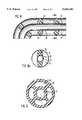
- FIG. 8is a view corresponding to FIG. 2 with a shaft of flexible construction
- FIG. 8ais a cross-section through the shaft according to FIG. 8.
- FIG. 9is a cross-section through a flexible shaft of modified construction.
- the hot gas applicatoressentially consists of an electric motor 2 accommodated in a handle 1 with electronic control means 3 for the calorific output and a fan 4 which is adjoined by a heating device 5 with a heating coil 6.
- a double-walled shaft 7is mounted releasably on the handle 1 with a union nut 8.
- the shaft 7has an outer tube 9 in which an inner tube 10 is guided.
- the inner tube 10forms a supply channel 11 which is connected to the delivery side of the fan 4 or to a chamber 12 surrounding the fan 4 and the heating device 5 and serves to conduct the heated gas to the distal end of the instrument.
- the outer tube 9forms with the inner tube 10 a channel 13 of annular cross-section which opens into a chamber 14 which is formed by the handle 1 and communicates with the intake side of the fan 4.
- the shaft 7which can be mounted releasably on the handle 1 of the hot gas applicator can be of different construction in its distal end region.
- the outer tube 9 and the inner tube 10are curved, wherein the inner tube 10 protrudes at its distal end 25 relative to that of the outer tube 9.
- the shaftis provided with an outer tube 9 which is sealed at the end face in its distal end region and constructed with a lateral opening 26.
- the inner tube 10is in this case curved in its distal end region and ends in the lateral opening 26, wherein the distal end 27 of the inner tube 10 is set back within the opening 26.
- FIG. 6opposite the distal end 28 of the outer tube 9 is a shield 29 connected thereto, and the distal end 30 of the inner tube 10 extends into a gap 31 between the distal end 28 of the outer tube 9 and the shield 29.
- the construction according to FIG. 7differs from the one according to FIG. 2 only in the design of the inner tube 10, of which the distal end is constructed as a nozzle 32 of narrower cross-section.
- the construction according to FIG. 8involves a flexible shaft in which projections 32 between inner tube 10 and outer tube 9 ensure mutual support thereof and coaxial guiding relative to each other.
- the outer tube 9 and the inner tube 10are in this case made of suitable plastic, wherein materials used for example with catheters can be used.
- the cross-section shown in FIG. 9shows an alternative embodiment of the flexible shaft made by extrusion, in which is used a tube profile 33 which encompasses the supply channel 11 and the channel 13 for the hot gas return, the channel 13 being formed from several partial channels 34.
- a moisture filter 15passes through the channel 13 according to FIG. 1, and the chamber 14 is provided with a pressure relief valve 16.
- the electric motor 2, the control means 3 and the connecting cable 17, i.e. the potential-carrying parts,are accommodated as shown in FIG. 1 in a separate support 18 which can be releasably connected to the handle 1 in a suitable manner.
- temperature sensors 20 and 21are arranged in the distal region of the channels 11 and 13 in the inner tube 10 and outer tube 9 respectively.
- the hot gas applicatorWhen using the hot gas applicator according to the invention, it is applied via a puncture wound to the point of the body cavity to be treated, and then the body cavity gas is blown by the fan 4, which is operated by means of the electric motor. 2, over the heating coil 6 of the heating device 5 and is heated. The heated gas then flows out in the distal direction through the inner tube 10 of the shaft forming the supply channel 11, to the tissue region to be heated or coagulated. At the same time extracted body cavity gas flows from the place of treatment back through the channel 13 between inner tube 10 and outer tube 9 and, after passing through the chamber 14, flows via gas inlet openings 19 into the housing of the fan 4 and from there, closing the circuit, back over the heating coil 6 into the body cavity.
- the temperature sensors 21, 20are arranged on the inside of the outer tube 9 of the shaft or on the inside of the inner tube 10 and connected to the control means 3 in the handle 1. With this construction the coagulation or heating temperature can always be adjusted, depending on the application, and in particular the temperature of the outer tube 9 can be limited to a physiologically acceptable value, e.g. 40° C.
- the processis further controlled by the pressure relief valve 16 which responds on exceeding a predetermined system pressure and opens temporarily, so that there cannot be inadmissible pressure rises inside the body cavity.
- the moisture filter 15which can be made of commercially available woven material and which lets moisture pass in only one direction, ensures that moisture from the body cavity is kept away from the gas circuit.
- hot gas applicator according to the inventiontakes place particularly advantageously without contact, wherein by changing corresponding nozzles which can be fitted onto the distal end piece of the shaft or otherwise fixed, in particular plane coagulation can be carried out.
- a closed coagulating end piece 22 as shown in FIG. 3is placed on the distal end instead of an open nozzle.
- This coagulating end piece 22is provided at the distal end with a non-stick coating 23 and advantageously constructed in cone form at the proximal end and arranged in such a way that the centre axes of the coagulating end piece 22 and of the inner tube 10 are aligned with each other, as a result of which favorable flow around the coagulating end piece 22 to be heated and satisfactory return flow of the hot gas within the annular channel 13 between the inner tube 10 and the outer tube 9 of the shaft are ensured.
- the temperature sensor 20 for control of the temperature of the hot gasis advantageously mounted in the region of the cone of the coagulating end piece 22, while the temperature sensor 21 for control of the maximum permitted outside temperature of the outer tube 9 of the shaft is arranged at approximately the same point as in the practical example according to FIG. 2.
- the applicator describedcan be adapted according to the respective requirements.
- FIG. 4allows lateral coagulation of tissue, wherein with the construction according to FIG. 5 coagulation focused more on certain points can be carried out, which is achieved by the fact that, when the outer tube 9 of the shaft is placed on the tissue, the inner tube 10 conducting the hot gas remains spaced apart from the tissue.
- FIG. 6it is possible to engage behind tissue and coagulate tissue selectively, wherein the shield 29 which engages at the back simultaneously ensures the protection of tissue behind it.
- FIG. 7A further refinement with respect to coagulation of a precise point is possible with the construction according to FIG. 7.
- FIGS. 8 and 9there is the possibility of adapting the applicator by simple deformation of such a shaft to diverse circumstances.
Landscapes
- Health & Medical Sciences (AREA)
- Surgery (AREA)
- Life Sciences & Earth Sciences (AREA)
- Biomedical Technology (AREA)
- Otolaryngology (AREA)
- Engineering & Computer Science (AREA)
- Nuclear Medicine, Radiotherapy & Molecular Imaging (AREA)
- Heart & Thoracic Surgery (AREA)
- Medical Informatics (AREA)
- Molecular Biology (AREA)
- Animal Behavior & Ethology (AREA)
- General Health & Medical Sciences (AREA)
- Public Health (AREA)
- Veterinary Medicine (AREA)
- Surgical Instruments (AREA)
Abstract
Description
The invention relates to an instrument for the application of hot gas for medical purposes, in particular for the heat treatment and coagulation of tissue, having a heating device for heating up gas which is conducted through a channel to the distal end of the instrument.
In endoscopy it is frequently necessary to heat tissues selectively for local application of heat or for coagulation, wherein basically a distinction is to be made between methods in which heat transfer takes place with direct contact of the tissue and methods in which heat transfer to the tissue takes place indirectly.
For instance, in DE-A-3 642 077 there is disclosed a device for high-frequency cutting and/or coagulation or for laser application. A further electrosurgical coagulation device is known from DE-A-3 710 489. Finally, from open surgery are also known cauterising tools for coagulation by means of gases, for example from EP-A-0 447 121 or from DE-C-75 016.
In the endoscopic use of such heat applying or coagulating instruments, the instrument for regional treatment of the body cavity with heat is for example introduced into the body cavity by a trocar. In such interventions the body cavity is frequently expanded, for which purpose gases are used, the gases being conducted under excess pressure into the body cavity. In coagulation by means of the above-mentioned devices, gases are produced which must be extracted from the body cavity, as they impair the view of the surgeon. In order to maintain the expansion of the body cavity, frequent postinsufflation of the supporting gas is therefore necessary.
In endoscopic use, the adaptation of gas coagulators of the kind described above does not offer a solution avoiding the disadvantages stated, because such devices in particular also have the disadvantage that in the case of incomplete combustion of the combustible gases used an explosive mixture can be formed. In the case of the subject according to DE-C-75 016 this mixture could be caused to explode by the open flame, or in a device according to EP-A-0 447 121 an explosion could be brought about due to arcing by the electrodes. Moreover with these methods residues would be formed by combustion of the gases, which would have to be removed very carefully from the body cavity.
The above-mentioned disadvantages concern first and foremost requirements connected with the necessary extraction of smoke and maintenance of the body cavity expansion. The disadvantages of electrically operated coagulating devices lie in particular in that basically an electrical potential is applied to the patient, owing to which in case of any breakdowns of the electrical system, for example due to insulation faults, there can be considerable danger to the patient. Potential-free systems such as laser coagulators are by contrast very elaborate and difficult to handle.
An object of the invention is to provide a hot gas applicator for regional heating and/or coagulation, in which an electrical potential which may possibly endanger the patient is not used and during application thereof the formation of explosive gas mixtures in the body cavity is prevented. Furthermore the gas pressure prevailing in the body cavity during application of this instrument should not be affected and a simple and cheap construction of the instrument should be made possible.
According to the invention in an instrument of the afore-mentioned kind, the gas is forced by means of a fan in circulation through the above-mentioned channel to the distal end of the instrument, and there with a diversion passes into a further channel and is conducted back to the heating device and the fan.
The advantages that can be obtained with this construction lie in particular in that the parameters of gas pressure and gas composition are preserved unchanged at the point of treatment during application.
The first channel which conducts the gas to the distal end of the instrument and the second channel which returns the gas to the fan may be formed by tubes extending coaxially with each other and together forming a shaft having inner and outer tubes, wherein the inner tube serves to supply gas, so that homogeneous gas conduction and favorable energy conversion are obtainable. In this case precise temperature regulation can be achieved by temperature sensing means which is arranged in each channel and which is connected to control means, this being in particular if the temperature sensing means is arranged in each case in the distal region of the channels. Aggregation, which is advantageous from the practical point of view, results if the fan, a drive thereof and the control means as well as the heating means are accommodated together in a handle of the instrument. By designing the handle with a releasable shaft and a removable electrical section, optimum conditions are fulfilled for disassembling and sterilising the whole system.
According to a further advantageous embodiment, the distal end of the shaft can be provided with different nozzles or with a closed coagulating end piece. Thus there is a possibility of adapting the instrument to different requirements, for example for carrying out multi-plane coagulations. Moreover for the purpose of keeping the system free from moisture from the body cavity, moisture filter means can be provided in the second channel as well as pressure relief valve means for avoiding inadmissible pressure increases in the body cavity. Finally the inner tube and the outer tube can be arranged axially slidably relative to each other, as a result of which on the one hand a tissue surface to be heated or coagulated can be treated with the hot gas from different distances and on the other hand nozzles of different constructions can be mounted as coagulating end pieces on the same shaft.
FIG. 1 is a longitudinal section through the handle of the hot gas applicator according to the invention;
FIG. 2 is a longitudinal section through the distal end region of the applicator according to FIG. 1;
FIG. 3 is a longitudinal section through the applicator corresponding to FIG. 2 with a modified end piece;
FIG. 4 is a view corresponding to FIG. 2 with a curved shaft in the distal end region;
FIG. 5 is a view corresponding to FIG. 2 with a shaft designed with a lateral opening in the distal end region;
FIG. 6 is a view corresponding to FIG. 2 with a shaft designed with a shield at the distal end;
FIG. 7 is a view corresponding to FIG. 2 with a nozzle of reduced cross-section arranged at the distal end;
FIG. 8 is a view corresponding to FIG. 2 with a shaft of flexible construction;
FIG. 8a is a cross-section through the shaft according to FIG. 8; and
FIG. 9 is a cross-section through a flexible shaft of modified construction.
The hot gas applicator according to the invention essentially consists of an electric motor 2 accommodated in a handle 1 with electronic control means 3 for the calorific output and a fan 4 which is adjoined by a heating device 5 with a heating coil 6. At the distal end of the instrument, a double-walled shaft 7 is mounted releasably on the handle 1 with a union nut 8.
As can be seen from FIG. 2, theshaft 7 has anouter tube 9 in which aninner tube 10 is guided. Theinner tube 10 forms asupply channel 11 which is connected to the delivery side of the fan 4 or to achamber 12 surrounding the fan 4 and the heating device 5 and serves to conduct the heated gas to the distal end of the instrument. Theouter tube 9 forms with the inner tube 10 achannel 13 of annular cross-section which opens into achamber 14 which is formed by the handle 1 and communicates with the intake side of the fan 4.
Theshaft 7 which can be mounted releasably on the handle 1 of the hot gas applicator can be of different construction in its distal end region. Thus according to FIG. 4 theouter tube 9 and theinner tube 10 are curved, wherein theinner tube 10 protrudes at itsdistal end 25 relative to that of theouter tube 9. According to FIG. 5 the shaft is provided with anouter tube 9 which is sealed at the end face in its distal end region and constructed with alateral opening 26. Theinner tube 10 is in this case curved in its distal end region and ends in thelateral opening 26, wherein thedistal end 27 of theinner tube 10 is set back within the opening 26.
In the construction according to FIG. 6, opposite the distal end 28 of theouter tube 9 is ashield 29 connected thereto, and thedistal end 30 of theinner tube 10 extends into a gap 31 between the distal end 28 of theouter tube 9 and theshield 29. The construction according to FIG. 7 differs from the one according to FIG. 2 only in the design of theinner tube 10, of which the distal end is constructed as anozzle 32 of narrower cross-section. Finally the construction according to FIG. 8 involves a flexible shaft in whichprojections 32 betweeninner tube 10 andouter tube 9 ensure mutual support thereof and coaxial guiding relative to each other. Theouter tube 9 and theinner tube 10 are in this case made of suitable plastic, wherein materials used for example with catheters can be used. The cross-section shown in FIG. 9 shows an alternative embodiment of the flexible shaft made by extrusion, in which is used atube profile 33 which encompasses thesupply channel 11 and thechannel 13 for the hot gas return, thechannel 13 being formed from severalpartial channels 34.
Amoisture filter 15 passes through thechannel 13 according to FIG. 1, and thechamber 14 is provided with apressure relief valve 16. The electric motor 2, the control means 3 and the connecting cable 17, i.e. the potential-carrying parts, are accommodated as shown in FIG. 1 in a separate support 18 which can be releasably connected to the handle 1 in a suitable manner. Finally as can be seen from FIG. 2temperature sensors channels inner tube 10 andouter tube 9 respectively.
When using the hot gas applicator according to the invention, it is applied via a puncture wound to the point of the body cavity to be treated, and then the body cavity gas is blown by the fan 4, which is operated by means of the electric motor. 2, over the heating coil 6 of the heating device 5 and is heated. The heated gas then flows out in the distal direction through theinner tube 10 of the shaft forming thesupply channel 11, to the tissue region to be heated or coagulated. At the same time extracted body cavity gas flows from the place of treatment back through thechannel 13 betweeninner tube 10 andouter tube 9 and, after passing through thechamber 14, flows viagas inlet openings 19 into the housing of the fan 4 and from there, closing the circuit, back over the heating coil 6 into the body cavity.
With this type of heating or coagulation of tissue, no smoke gases which would have to be extracted are produced during operation, on account of which the respective body cavity pressure will also as a rule remain unchanged. Due to gas return via thechannel 13 betweeninner tube 10 andouter tube 9 of the shaft, as a further advantage, no high temperatures can arise on the outer wall of theouter tube 9. Moreover further temperature compensation is achieved by the additional intake of ambient air or body cavity gas.
Thetemperature sensors outer tube 9 of the shaft or on the inside of theinner tube 10 and connected to the control means 3 in the handle 1. With this construction the coagulation or heating temperature can always be adjusted, depending on the application, and in particular the temperature of theouter tube 9 can be limited to a physiologically acceptable value, e.g. 40° C.
The process is further controlled by thepressure relief valve 16 which responds on exceeding a predetermined system pressure and opens temporarily, so that there cannot be inadmissible pressure rises inside the body cavity. Finally themoisture filter 15, which can be made of commercially available woven material and which lets moisture pass in only one direction, ensures that moisture from the body cavity is kept away from the gas circuit.
As described above, the handle 1 can be separated from theshaft 7 by unscrewing the union nut 8. This and the releasability of the support 18 with the potential-carrying parts of the applicator instrument allow optimum disassembling and sterilisability of the whole system.
Use of the hot gas applicator according to the invention takes place particularly advantageously without contact, wherein by changing corresponding nozzles which can be fitted onto the distal end piece of the shaft or otherwise fixed, in particular plane coagulation can be carried out.
Furthermore it is also possible, for carrying out contact coagulation, to place a closedcoagulating end piece 22 as shown in FIG. 3 on the distal end instead of an open nozzle. This coagulatingend piece 22 is provided at the distal end with anon-stick coating 23 and advantageously constructed in cone form at the proximal end and arranged in such a way that the centre axes of the coagulatingend piece 22 and of theinner tube 10 are aligned with each other, as a result of which favorable flow around the coagulatingend piece 22 to be heated and satisfactory return flow of the hot gas within theannular channel 13 between theinner tube 10 and theouter tube 9 of the shaft are ensured. By providing the conical portion of the coagulatingend piece 22 which is exposed to the hot gas stream withlamellae 24, improved heat exchange is achieved due to the increased area of contact. In the construction with a coagulatingend piece 22, thetemperature sensor 20 for control of the temperature of the hot gas is advantageously mounted in the region of the cone of the coagulatingend piece 22, while thetemperature sensor 21 for control of the maximum permitted outside temperature of theouter tube 9 of the shaft is arranged at approximately the same point as in the practical example according to FIG. 2.
With selective use of the variants of the shaft shown in FIGS. 4 to 8, the applicator described can be adapted according to the respective requirements.
Thus the construction according to FIG. 4 allows lateral coagulation of tissue, wherein with the construction according to FIG. 5 coagulation focused more on certain points can be carried out, which is achieved by the fact that, when theouter tube 9 of the shaft is placed on the tissue, theinner tube 10 conducting the hot gas remains spaced apart from the tissue. With the construction according to FIG. 6 it is possible to engage behind tissue and coagulate tissue selectively, wherein theshield 29 which engages at the back simultaneously ensures the protection of tissue behind it. A further refinement with respect to coagulation of a precise point is possible with the construction according to FIG. 7. Finally with the flexible construction of the shaft according to FIGS. 8 and 9 there is the possibility of adapting the applicator by simple deformation of such a shaft to diverse circumstances.
Claims (13)
1. An instrument for applying hot gas for heat treatment and coagulation of tissue in a body cavity, comprising:
a double-walled shaft forming two coaxial tubes which respectively define a first channel and a second channel, the shaft having a proximal end and a distal end;
heating means arranged at the proximal end of the shaft for heating up insufflation gas in the body cavity;
fan means arranged at the proximal end of the shaft for drawing the gas into an outer one of the tubes at the distal end of the shaft, back through the outer tube to the heating means and fan means at the proximal end of the shaft, and circulating the heated gas through an inner one of the tubes from the proximal end to the distal end; and
temperature sensing means arranged in each of the tubes for sensing gas temperature within the tubes.
2. The instrument according to claim 1, wherein the temperature sensing means are arranged near the distal end of the shaft.
3. The instrument according to claim 1, and further comprising a handle connected to the proximal end of the shaft, the fan means and the heating means being arranged within the handle.
4. The instrument according to claim 1, wherein the handle and the proximal end of the shaft are releasably connected together.
5. The instrument according to claim 1, wherein the distal end of the shaft is formed as a nozzle.
6. The instrument according to claim 1, wherein the outer tube and the inner tube of the shaft each have a curved distal end, the distal end of the inner tube being configured to protrude from the distal end of the outer tube.
7. The instrument according to claim 1, wherein the outer tube has a distal end which is sealed and provided with a lateral opening and the inner tube has a distal end which is curved and set back within the lateral opening.
8. The instrument according to claim 1, wherein the outer tube has a distal end and a shield located opposite said distal end so as to form a gap, and the inner tube has a distal end which extends into the gap.
9. The instrument according to claim 1, wherein the outer tube and the inner tube are flexible and further comprising projection means for guiding the inner tube coaxially relative to the outer tube.
10. The instrument according to claim 9, wherein the flexible shaft is formed from a hollow plastic profile which forms the first and second channels and the second channel comprises several partial channels.
11. The instrument according to claim 1, and further comprising a closed coagulating end piece at the distal end of the shaft.
12. The instrument according to claim 1, and further comprising moisture filter means and pressure relief valve means, said moisture filter means being located in said second channel and being connected to said valve means.
13. The instrument according to claim 1, wherein the inner tube and the outer tube are arranged axially slidably relative to one another.
Applications Claiming Priority (2)
| Application Number | Priority Date | Filing Date | Title |
|---|---|---|---|
| DE4338866ADE4338866C1 (en) | 1993-11-13 | 1993-11-13 | Medical instrument for the application of hot gas |
| DE4338866.3 | 1993-11-13 |
Publications (1)
| Publication Number | Publication Date |
|---|---|
| US5620440Atrue US5620440A (en) | 1997-04-15 |
Family
ID=6502572
Family Applications (1)
| Application Number | Title | Priority Date | Filing Date |
|---|---|---|---|
| US08/338,331Expired - Fee RelatedUS5620440A (en) | 1993-11-13 | 1994-11-14 | Medical instrument for applying hot gas |
Country Status (4)
| Country | Link |
|---|---|
| US (1) | US5620440A (en) |
| DE (1) | DE4338866C1 (en) |
| FR (1) | FR2712171B1 (en) |
| GB (1) | GB2283681B (en) |
Cited By (66)
| Publication number | Priority date | Publication date | Assignee | Title |
|---|---|---|---|---|
| US5893838A (en)* | 1997-08-15 | 1999-04-13 | Therox, Inc. | System and method for high pressure delivery of gas-supersaturated fluids |
| US5964752A (en)* | 1998-02-02 | 1999-10-12 | Stone; Kevin R. | Articular cartilage surface shaping apparatus and method |
| US5984920A (en)* | 1997-05-09 | 1999-11-16 | Medi-Globe Corporation | Rotatable sphincterotome/papillotome and method of use |
| WO2000011927A3 (en)* | 1998-08-18 | 2000-05-04 | Gennady Viktorovich Mamaev | Method for dissecting tissues, device for simultaneously dissecting and coagulating the same and variants thereof |
| US6215955B1 (en)* | 1999-04-02 | 2001-04-10 | Liquid Resins International, Ltd. | Heating/dryer system for use in repairing chips in glass |
| US20030181857A1 (en)* | 2002-03-22 | 2003-09-25 | James Blake | Insufflation device with integral heater control |
| US6632194B1 (en)* | 1999-11-17 | 2003-10-14 | W.O.M. World Of Medicine Gmbh | Device for insufflating gas |
| US20040068306A1 (en)* | 2000-12-09 | 2004-04-08 | Shadduck John H. | Medical instruments and techniques for thermally-medicated therapies |
| US20040260280A1 (en)* | 2003-05-01 | 2004-12-23 | Sartor Joe Don | Suction coagulator with dissecting probe |
| US20050154384A1 (en)* | 2003-12-23 | 2005-07-14 | Joshua Ben-Nun | Thermal airflow tool and system |
| US20050222415A1 (en)* | 2002-05-21 | 2005-10-06 | Yatendra Kumar | Process for the preparation of rosuvastatin |
| US20060047291A1 (en)* | 2004-08-20 | 2006-03-02 | Uptake Medical Corporation | Non-foreign occlusion of an airway and lung collapse |
| US7008535B1 (en) | 2000-08-04 | 2006-03-07 | Wayne State University | Apparatus for oxygenating wastewater |
| WO2006055695A1 (en)* | 2004-11-16 | 2006-05-26 | Barry Robert L | Device and method for lung treatment |
| US20060129098A1 (en)* | 2004-12-09 | 2006-06-15 | Applied Medical Resources Corporation | Insufflation gas warmer and humidifier |
| US20060130830A1 (en)* | 2004-09-07 | 2006-06-22 | Uptake Medical Corporation | Intra-bronchial implants for improved attachment |
| US20060135955A1 (en)* | 2003-01-18 | 2006-06-22 | Shadduck John H | Medical instrument and method of use |
| US20060224154A1 (en)* | 2001-12-07 | 2006-10-05 | Shadduck John H | Medical instrument and method of use |
| US20060229603A1 (en)* | 2005-03-18 | 2006-10-12 | Olsen Ron A | Adjustable splint for osteosynthesis with modular joint |
| US20080114297A1 (en)* | 2006-11-13 | 2008-05-15 | Uptake Medical Corp. | High pressure and high temperature vapor catheters and systems |
| US20080110457A1 (en)* | 2006-11-13 | 2008-05-15 | Uptake Medical Corp. | Treatment with high temperature vapor |
| US20080132826A1 (en)* | 2003-01-18 | 2008-06-05 | Shadduck John H | Medical instruments and techniques for treating pulmonary disorders |
| WO2009009398A1 (en) | 2007-07-06 | 2009-01-15 | Tsunami Medtech, Llc | Medical system and method of use |
| US20090105703A1 (en)* | 2000-12-09 | 2009-04-23 | Shadduck John H | Method for treating tissue |
| US20090138001A1 (en)* | 2007-10-22 | 2009-05-28 | Barry Robert L | Determining Patient-Specific Vapor Treatment and Delivery Parameters |
| US20090216220A1 (en)* | 2008-02-20 | 2009-08-27 | Tsunami Medtech, Llc | Medical system and method of use |
| US20090306640A1 (en)* | 2008-06-06 | 2009-12-10 | Grant Michael Glaze | Vein Therapy Device and Method |
| US20090301483A1 (en)* | 2007-10-22 | 2009-12-10 | Barry Robert L | Determining Patient-Specific Vapor Treatment and Delivery Parameters |
| US20100114082A1 (en)* | 2008-10-06 | 2010-05-06 | Sharma Virender K | Method and Apparatus for the Ablation of Endometrial Tissue |
| US20100185189A1 (en)* | 2005-08-03 | 2010-07-22 | Tsunami Medtech, Llc | Medical system and method of use |
| US20100198209A1 (en)* | 2009-01-30 | 2010-08-05 | Tartaglia Joseph M | Hemorrhoid Therapy and Method |
| US20100204688A1 (en)* | 2008-09-09 | 2010-08-12 | Michael Hoey | Medical system and method of use |
| US7777130B2 (en) | 2007-06-18 | 2010-08-17 | Vivant Medical, Inc. | Microwave cable cooling |
| US20100234794A1 (en)* | 2009-03-12 | 2010-09-16 | Kevin Shaun Weadock | System and method for reducing surgical site infection |
| US20100262133A1 (en)* | 2009-02-03 | 2010-10-14 | Tsunami Medtech, Llc | Medical systems and methods for ablating and absorbing tissue |
| US20110087160A1 (en)* | 2009-10-09 | 2011-04-14 | John Temple | Insufflation gas heater system and tubing for use therewith |
| US20110106071A1 (en)* | 2009-10-29 | 2011-05-05 | Bosel Christopher D | Thermochemical ablation needle |
| US8579888B2 (en) | 2008-06-17 | 2013-11-12 | Tsunami Medtech, Llc | Medical probes for the treatment of blood vessels |
| US8900223B2 (en) | 2009-11-06 | 2014-12-02 | Tsunami Medtech, Llc | Tissue ablation systems and methods of use |
| US9161801B2 (en) | 2009-12-30 | 2015-10-20 | Tsunami Medtech, Llc | Medical system and method of use |
| US9433457B2 (en) | 2000-12-09 | 2016-09-06 | Tsunami Medtech, Llc | Medical instruments and techniques for thermally-mediated therapies |
| US9561068B2 (en) | 2008-10-06 | 2017-02-07 | Virender K. Sharma | Method and apparatus for tissue ablation |
| US9561066B2 (en) | 2008-10-06 | 2017-02-07 | Virender K. Sharma | Method and apparatus for tissue ablation |
| US9561067B2 (en) | 2008-10-06 | 2017-02-07 | Virender K. Sharma | Method and apparatus for tissue ablation |
| US9782211B2 (en) | 2013-10-01 | 2017-10-10 | Uptake Medical Technology Inc. | Preferential volume reduction of diseased segments of a heterogeneous lobe |
| US9943353B2 (en) | 2013-03-15 | 2018-04-17 | Tsunami Medtech, Llc | Medical system and method of use |
| US10064697B2 (en) | 2008-10-06 | 2018-09-04 | Santa Anna Tech Llc | Vapor based ablation system for treating various indications |
| US10179019B2 (en) | 2014-05-22 | 2019-01-15 | Aegea Medical Inc. | Integrity testing method and apparatus for delivering vapor to the uterus |
| US10238446B2 (en) | 2010-11-09 | 2019-03-26 | Aegea Medical Inc. | Positioning method and apparatus for delivering vapor to the uterus |
| USD845467S1 (en) | 2017-09-17 | 2019-04-09 | Uptake Medical Technology Inc. | Hand-piece for medical ablation catheter |
| US10299856B2 (en) | 2014-05-22 | 2019-05-28 | Aegea Medical Inc. | Systems and methods for performing endometrial ablation |
| US10485604B2 (en) | 2014-12-02 | 2019-11-26 | Uptake Medical Technology Inc. | Vapor treatment of lung nodules and tumors |
| US10531906B2 (en) | 2015-02-02 | 2020-01-14 | Uptake Medical Technology Inc. | Medical vapor generator |
| US10695126B2 (en) | 2008-10-06 | 2020-06-30 | Santa Anna Tech Llc | Catheter with a double balloon structure to generate and apply a heated ablative zone to tissue |
| US10758292B2 (en) | 2007-08-23 | 2020-09-01 | Aegea Medical Inc. | Uterine therapy device and method |
| US10881442B2 (en) | 2011-10-07 | 2021-01-05 | Aegea Medical Inc. | Integrity testing method and apparatus for delivering vapor to the uterus |
| US11129673B2 (en) | 2017-05-05 | 2021-09-28 | Uptake Medical Technology Inc. | Extra-airway vapor ablation for treating airway constriction in patients with asthma and COPD |
| US11331140B2 (en) | 2016-05-19 | 2022-05-17 | Aqua Heart, Inc. | Heated vapor ablation systems and methods for treating cardiac conditions |
| US11331037B2 (en) | 2016-02-19 | 2022-05-17 | Aegea Medical Inc. | Methods and apparatus for determining the integrity of a bodily cavity |
| US11344364B2 (en) | 2017-09-07 | 2022-05-31 | Uptake Medical Technology Inc. | Screening method for a target nerve to ablate for the treatment of inflammatory lung disease |
| US11350988B2 (en) | 2017-09-11 | 2022-06-07 | Uptake Medical Technology Inc. | Bronchoscopic multimodality lung tumor treatment |
| US11419658B2 (en) | 2017-11-06 | 2022-08-23 | Uptake Medical Technology Inc. | Method for treating emphysema with condensable thermal vapor |
| US11490946B2 (en) | 2017-12-13 | 2022-11-08 | Uptake Medical Technology Inc. | Vapor ablation handpiece |
| US11653927B2 (en) | 2019-02-18 | 2023-05-23 | Uptake Medical Technology Inc. | Vapor ablation treatment of obstructive lung disease |
| US11806066B2 (en) | 2018-06-01 | 2023-11-07 | Santa Anna Tech Llc | Multi-stage vapor-based ablation treatment methods and vapor generation and delivery systems |
| US12364537B2 (en) | 2016-05-02 | 2025-07-22 | Santa Anna Tech Llc | Catheter with a double balloon structure to generate and apply a heated ablative zone to tissue |
Families Citing this family (1)
| Publication number | Priority date | Publication date | Assignee | Title |
|---|---|---|---|---|
| EP1170066A1 (en) | 2000-07-05 | 2002-01-09 | Förnsel, Peter | Process and apparatus for cleaning rollers and bands |
Citations (4)
| Publication number | Priority date | Publication date | Assignee | Title |
|---|---|---|---|---|
| US319698A (en)* | 1885-06-09 | Gas-cautery | ||
| US3434476A (en)* | 1966-04-07 | 1969-03-25 | Robert F Shaw | Plasma arc scalpel |
| US4796622A (en)* | 1987-03-06 | 1989-01-10 | The United States Of America As Represented By The Department Of Health And Human Services | Catheter with oxyhydrogen catalytic thermal tip |
| US5444215A (en)* | 1989-03-03 | 1995-08-22 | Bauer; Rudolf | Hairdressing device with first and second blowers |
Family Cites Families (11)
| Publication number | Priority date | Publication date | Assignee | Title |
|---|---|---|---|---|
| DE75016C (en)* | Dr. C. A. PAQUELIN in Paris, Place Vendöme | Burning tool with movable heating tube | ||
| US2734508A (en)* | 1956-02-14 | Kozinski | ||
| GB1336270A (en)* | 1971-10-29 | 1973-11-07 | St Clair M | Therapeutic apparatus |
| GB1582135A (en)* | 1976-07-14 | 1980-12-31 | Ferranti Ltd | Heaters |
| DE2800825A1 (en)* | 1978-01-10 | 1979-07-12 | Friedrich Dipl Phys Dr Bodem | Miniature gas heater for processing difficult access surfaces - has long thin tube through which gas is passed to electric heater in front of jet |
| US4781175A (en)* | 1986-04-08 | 1988-11-01 | C. R. Bard, Inc. | Electrosurgical conductive gas stream technique of achieving improved eschar for coagulation |
| DE3642077C2 (en)* | 1986-12-10 | 1996-09-12 | Storz Karl Gmbh & Co | Device with a generator and an associated application probe |
| DD276424A1 (en)* | 1988-10-27 | 1990-02-28 | Carus Carl Gustav | HEISSLUFTKOAGULATOR |
| US5061268A (en)* | 1989-08-24 | 1991-10-29 | Beacon Laboratories, Inc. | Disposable electrosurgical pencil with in-line filter and method |
| US5088997A (en)* | 1990-03-15 | 1992-02-18 | Valleylab, Inc. | Gas coagulation device |
| DE4139029C2 (en)* | 1991-11-27 | 1996-05-23 | Erbe Elektromedizin | Device for the coagulation of biological tissues |
- 1993
- 1993-11-13DEDE4338866Apatent/DE4338866C1/ennot_activeExpired - Fee Related
- 1994
- 1994-11-04GBGB9422324Apatent/GB2283681B/ennot_activeExpired - Fee Related
- 1994-11-09FRFR9413490Apatent/FR2712171B1/ennot_activeExpired - Fee Related
- 1994-11-14USUS08/338,331patent/US5620440A/ennot_activeExpired - Fee Related
Patent Citations (4)
| Publication number | Priority date | Publication date | Assignee | Title |
|---|---|---|---|---|
| US319698A (en)* | 1885-06-09 | Gas-cautery | ||
| US3434476A (en)* | 1966-04-07 | 1969-03-25 | Robert F Shaw | Plasma arc scalpel |
| US4796622A (en)* | 1987-03-06 | 1989-01-10 | The United States Of America As Represented By The Department Of Health And Human Services | Catheter with oxyhydrogen catalytic thermal tip |
| US5444215A (en)* | 1989-03-03 | 1995-08-22 | Bauer; Rudolf | Hairdressing device with first and second blowers |
Cited By (154)
| Publication number | Priority date | Publication date | Assignee | Title |
|---|---|---|---|---|
| US5984920A (en)* | 1997-05-09 | 1999-11-16 | Medi-Globe Corporation | Rotatable sphincterotome/papillotome and method of use |
| US7104289B2 (en) | 1997-08-15 | 2006-09-12 | Therox, Inc. | System and method for high pressure delivery of gas-supersaturated fluids |
| US6782924B2 (en) | 1997-08-15 | 2004-08-31 | Therox, Inc. | System and method for high pressure delivery of gas-supersaturated fluids |
| US6030357A (en)* | 1997-08-15 | 2000-02-29 | Therox, Inc. | System and method for high pressure delivery of gas-supersaturated fluids |
| US20060264811A1 (en)* | 1997-08-15 | 2006-11-23 | Therox, Inc. | System and method for high pressure delivery of gas-supersaturated fluids"[method of making perfluorocarbon emulsions with non-fluorinated surfactants] |
| US5893838A (en)* | 1997-08-15 | 1999-04-13 | Therox, Inc. | System and method for high pressure delivery of gas-supersaturated fluids |
| US7641628B2 (en) | 1997-08-15 | 2010-01-05 | Therox, Inc. | System and method for high pressure delivery of gas-supersaturated fluids |
| US6315754B1 (en) | 1997-08-15 | 2001-11-13 | Therox, Inc. | System and method for high pressure delivery of gas-supersaturated fluids |
| US20010008960A1 (en)* | 1997-08-15 | 2001-07-19 | Daoud Adib G. | System and method for high pressure delivery of gas-supersaturated floids |
| US5964752A (en)* | 1998-02-02 | 1999-10-12 | Stone; Kevin R. | Articular cartilage surface shaping apparatus and method |
| US8187269B2 (en) | 1998-03-27 | 2012-05-29 | Tsunami Medtech, Llc | Medical instruments and techniques for treating pulmonary disorders |
| US9204889B2 (en) | 1998-03-27 | 2015-12-08 | Tsunami Medtech, Llc | Medical instrument and method of use |
| US8858549B2 (en) | 1998-03-27 | 2014-10-14 | Tsunami Medtech, Llc | Medical instruments and techniques for treating pulmonary disorders |
| WO2000011927A3 (en)* | 1998-08-18 | 2000-05-04 | Gennady Viktorovich Mamaev | Method for dissecting tissues, device for simultaneously dissecting and coagulating the same and variants thereof |
| US6215955B1 (en)* | 1999-04-02 | 2001-04-10 | Liquid Resins International, Ltd. | Heating/dryer system for use in repairing chips in glass |
| US6632194B1 (en)* | 1999-11-17 | 2003-10-14 | W.O.M. World Of Medicine Gmbh | Device for insufflating gas |
| US7008535B1 (en) | 2000-08-04 | 2006-03-07 | Wayne State University | Apparatus for oxygenating wastewater |
| US7294278B2 (en) | 2000-08-04 | 2007-11-13 | Wayne State University | Method for oxygenating wastewater |
| US9433457B2 (en) | 2000-12-09 | 2016-09-06 | Tsunami Medtech, Llc | Medical instruments and techniques for thermally-mediated therapies |
| US10524847B2 (en) | 2000-12-09 | 2020-01-07 | Tsunami Medtech, Llc | Medical instruments and techniques for thermally-mediated therapies |
| US20090105703A1 (en)* | 2000-12-09 | 2009-04-23 | Shadduck John H | Method for treating tissue |
| US7674259B2 (en) | 2000-12-09 | 2010-03-09 | Tsunami Medtech | Medical instruments and techniques for thermally-mediated therapies |
| US9615875B2 (en) | 2000-12-09 | 2017-04-11 | Tsunami Med Tech, LLC | Medical instruments and techniques for thermally-mediated therapies |
| US10675079B2 (en) | 2000-12-09 | 2020-06-09 | Tsunami Medtech, Llc | Method for treating tissue |
| US8758341B2 (en) | 2000-12-09 | 2014-06-24 | Tsunami Medtech, Llc | Thermotherapy device |
| US8574226B2 (en) | 2000-12-09 | 2013-11-05 | Tsunami Medtech, Llc | Method for treating tissue |
| US20040068306A1 (en)* | 2000-12-09 | 2004-04-08 | Shadduck John H. | Medical instruments and techniques for thermally-medicated therapies |
| US9468487B2 (en) | 2001-12-07 | 2016-10-18 | Tsunami Medtech, Llc | Medical instrument and method of use |
| US8444636B2 (en) | 2001-12-07 | 2013-05-21 | Tsunami Medtech, Llc | Medical instrument and method of use |
| US20060224154A1 (en)* | 2001-12-07 | 2006-10-05 | Shadduck John H | Medical instrument and method of use |
| US20030181857A1 (en)* | 2002-03-22 | 2003-09-25 | James Blake | Insufflation device with integral heater control |
| US20050222415A1 (en)* | 2002-05-21 | 2005-10-06 | Yatendra Kumar | Process for the preparation of rosuvastatin |
| US20060135955A1 (en)* | 2003-01-18 | 2006-06-22 | Shadduck John H | Medical instrument and method of use |
| US8313485B2 (en) | 2003-01-18 | 2012-11-20 | Tsunami Medtech, Llc | Method for performing lung volume reduction |
| US20080132826A1 (en)* | 2003-01-18 | 2008-06-05 | Shadduck John H | Medical instruments and techniques for treating pulmonary disorders |
| US9113944B2 (en) | 2003-01-18 | 2015-08-25 | Tsunami Medtech, Llc | Method for performing lung volume reduction |
| US7892229B2 (en) | 2003-01-18 | 2011-02-22 | Tsunami Medtech, Llc | Medical instruments and techniques for treating pulmonary disorders |
| US8016823B2 (en) | 2003-01-18 | 2011-09-13 | Tsunami Medtech, Llc | Medical instrument and method of use |
| US20040260280A1 (en)* | 2003-05-01 | 2004-12-23 | Sartor Joe Don | Suction coagulator with dissecting probe |
| US7537594B2 (en) | 2003-05-01 | 2009-05-26 | Covidien Ag | Suction coagulator with dissecting probe |
| US8579892B2 (en) | 2003-10-07 | 2013-11-12 | Tsunami Medtech, Llc | Medical system and method of use |
| US9907599B2 (en) | 2003-10-07 | 2018-03-06 | Tsunami Medtech, Llc | Medical system and method of use |
| US20050154384A1 (en)* | 2003-12-23 | 2005-07-14 | Joshua Ben-Nun | Thermal airflow tool and system |
| US7585295B2 (en)* | 2003-12-23 | 2009-09-08 | Itos International Ltd. | Thermal airflow tool and system |
| US20060047291A1 (en)* | 2004-08-20 | 2006-03-02 | Uptake Medical Corporation | Non-foreign occlusion of an airway and lung collapse |
| US20060130830A1 (en)* | 2004-09-07 | 2006-06-22 | Uptake Medical Corporation | Intra-bronchial implants for improved attachment |
| WO2006055695A1 (en)* | 2004-11-16 | 2006-05-26 | Barry Robert L | Device and method for lung treatment |
| CN101115448B (en)* | 2004-11-16 | 2010-05-12 | 罗伯特·L·巴里 | Devices and methods for lung treatment |
| US9050076B2 (en) | 2004-11-16 | 2015-06-09 | Uptake Medical Corp. | Device and method for lung treatment |
| US9642668B2 (en) | 2004-11-16 | 2017-05-09 | Uptake Medical Technology Inc. | Device and method for lung treatment |
| US11839418B2 (en) | 2004-11-16 | 2023-12-12 | Uptake Medical Technology Inc. | Device and method for lung treatment |
| US20060161233A1 (en)* | 2004-11-16 | 2006-07-20 | Uptake Medical Corp. | Device and method for lung treatment |
| US7913698B2 (en) | 2004-11-16 | 2011-03-29 | Uptake Medical Corp. | Device and method for lung treatment |
| US20110172654A1 (en)* | 2004-11-16 | 2011-07-14 | Barry Robert L | Device and Method for Lung Treatment |
| US20110028890A1 (en)* | 2004-12-09 | 2011-02-03 | Applied Medical Resources Corporation | Insufflation gas warmer and humidifier |
| US8632490B2 (en) | 2004-12-09 | 2014-01-21 | Applied Medical Resources Corporation | Insufflation gas warmer and humidifier |
| US20060129098A1 (en)* | 2004-12-09 | 2006-06-15 | Applied Medical Resources Corporation | Insufflation gas warmer and humidifier |
| US8133196B2 (en) | 2004-12-09 | 2012-03-13 | Applied Medical Resources Corporation | Insufflation gas warmer and humidifier |
| US7811253B2 (en) | 2004-12-09 | 2010-10-12 | Applied Medical Resources Corporation | Insufflation gas warmer and humidifier |
| US20060229603A1 (en)* | 2005-03-18 | 2006-10-12 | Olsen Ron A | Adjustable splint for osteosynthesis with modular joint |
| US20100185189A1 (en)* | 2005-08-03 | 2010-07-22 | Tsunami Medtech, Llc | Medical system and method of use |
| US8579893B2 (en) | 2005-08-03 | 2013-11-12 | Tsunami Medtech, Llc | Medical system and method of use |
| US20080114297A1 (en)* | 2006-11-13 | 2008-05-15 | Uptake Medical Corp. | High pressure and high temperature vapor catheters and systems |
| US9113858B2 (en) | 2006-11-13 | 2015-08-25 | Uptake Medical Corp. | High pressure and high temperature vapor catheters and systems |
| US20080110457A1 (en)* | 2006-11-13 | 2008-05-15 | Uptake Medical Corp. | Treatment with high temperature vapor |
| US7993323B2 (en) | 2006-11-13 | 2011-08-09 | Uptake Medical Corp. | High pressure and high temperature vapor catheters and systems |
| US8585645B2 (en) | 2006-11-13 | 2013-11-19 | Uptake Medical Corp. | Treatment with high temperature vapor |
| US20100243287A1 (en)* | 2007-06-18 | 2010-09-30 | Vivant Medical, Inc. | Microwave Cable Cooling |
| US8093500B2 (en) | 2007-06-18 | 2012-01-10 | Vivant Medical, Inc. | Microwave cable cooling |
| US7777130B2 (en) | 2007-06-18 | 2010-08-17 | Vivant Medical, Inc. | Microwave cable cooling |
| WO2009009398A1 (en) | 2007-07-06 | 2009-01-15 | Tsunami Medtech, Llc | Medical system and method of use |
| US11207118B2 (en) | 2007-07-06 | 2021-12-28 | Tsunami Medtech, Llc | Medical system and method of use |
| EP2170198A4 (en)* | 2007-07-06 | 2011-03-30 | Tsunami Medtech Llc | Medical system and method of use |
| US11213338B2 (en) | 2007-08-23 | 2022-01-04 | Aegea Medical Inc. | Uterine therapy device and method |
| US10758292B2 (en) | 2007-08-23 | 2020-09-01 | Aegea Medical Inc. | Uterine therapy device and method |
| US8734380B2 (en) | 2007-10-22 | 2014-05-27 | Uptake Medical Corp. | Determining patient-specific vapor treatment and delivery parameters |
| US20090138001A1 (en)* | 2007-10-22 | 2009-05-28 | Barry Robert L | Determining Patient-Specific Vapor Treatment and Delivery Parameters |
| US8322335B2 (en) | 2007-10-22 | 2012-12-04 | Uptake Medical Corp. | Determining patient-specific vapor treatment and delivery parameters |
| US20090301483A1 (en)* | 2007-10-22 | 2009-12-10 | Barry Robert L | Determining Patient-Specific Vapor Treatment and Delivery Parameters |
| US8147532B2 (en) | 2007-10-22 | 2012-04-03 | Uptake Medical Corp. | Determining patient-specific vapor treatment and delivery parameters |
| US9924992B2 (en) | 2008-02-20 | 2018-03-27 | Tsunami Medtech, Llc | Medical system and method of use |
| US10595925B2 (en) | 2008-02-20 | 2020-03-24 | Tsunami Medtech, Llc | Medical system and method of use |
| US20090216220A1 (en)* | 2008-02-20 | 2009-08-27 | Tsunami Medtech, Llc | Medical system and method of use |
| US11129664B2 (en) | 2008-05-31 | 2021-09-28 | Tsunami Medtech, Llc | Systems and methods for delivering energy into a target tissue of a body |
| US11478291B2 (en) | 2008-05-31 | 2022-10-25 | Tsunami Medtech, Llc | Methods for delivering energy into a target tissue of a body |
| US11284932B2 (en) | 2008-05-31 | 2022-03-29 | Tsunami Medtech, Llc | Methods for delivering energy into a target tissue of a body |
| US11179187B2 (en) | 2008-05-31 | 2021-11-23 | Tsunami Medtech, Llc | Methods for delivering energy into a target tissue of a body |
| US11141210B2 (en) | 2008-05-31 | 2021-10-12 | Tsunami Medtech, Llc | Systems and methods for delivering energy into a target tissue of a body |
| US20090306640A1 (en)* | 2008-06-06 | 2009-12-10 | Grant Michael Glaze | Vein Therapy Device and Method |
| US8911430B2 (en) | 2008-06-17 | 2014-12-16 | Tsunami Medtech, Llc | Medical probes for the treatment of blood vessels |
| US8579888B2 (en) | 2008-06-17 | 2013-11-12 | Tsunami Medtech, Llc | Medical probes for the treatment of blood vessels |
| US8721632B2 (en) | 2008-09-09 | 2014-05-13 | Tsunami Medtech, Llc | Methods for delivering energy into a target tissue of a body |
| US20100204688A1 (en)* | 2008-09-09 | 2010-08-12 | Michael Hoey | Medical system and method of use |
| US10548653B2 (en) | 2008-09-09 | 2020-02-04 | Tsunami Medtech, Llc | Methods for delivering energy into a target tissue of a body |
| US10842549B2 (en) | 2008-10-06 | 2020-11-24 | Santa Anna Tech Llc | Vapor ablation system with a catheter having more than one positioning element and configured to treat pulmonary tissue |
| US9561067B2 (en) | 2008-10-06 | 2017-02-07 | Virender K. Sharma | Method and apparatus for tissue ablation |
| US9700365B2 (en) | 2008-10-06 | 2017-07-11 | Santa Anna Tech Llc | Method and apparatus for the ablation of gastrointestinal tissue |
| US10842548B2 (en) | 2008-10-06 | 2020-11-24 | Santa Anna Tech Llc | Vapor ablation system with a catheter having more than one positioning element |
| US12310650B2 (en) | 2008-10-06 | 2025-05-27 | Santa Anna Tech Llc | Methods of ablating tissue using time-limited treatment periods |
| US10064697B2 (en) | 2008-10-06 | 2018-09-04 | Santa Anna Tech Llc | Vapor based ablation system for treating various indications |
| US11813014B2 (en) | 2008-10-06 | 2023-11-14 | Santa Anna Tech Llc | Methods and systems for directed tissue ablation |
| US11779430B2 (en) | 2008-10-06 | 2023-10-10 | Santa Anna Tech Llc | Vapor based ablation system for treating uterine bleeding |
| US11589920B2 (en) | 2008-10-06 | 2023-02-28 | Santa Anna Tech Llc | Catheter with a double balloon structure to generate and apply an ablative zone to tissue |
| US10842557B2 (en) | 2008-10-06 | 2020-11-24 | Santa Anna Tech Llc | Vapor ablation system with a catheter having more than one positioning element and configured to treat duodenal tissue |
| US9561068B2 (en) | 2008-10-06 | 2017-02-07 | Virender K. Sharma | Method and apparatus for tissue ablation |
| US9561066B2 (en) | 2008-10-06 | 2017-02-07 | Virender K. Sharma | Method and apparatus for tissue ablation |
| US10695126B2 (en) | 2008-10-06 | 2020-06-30 | Santa Anna Tech Llc | Catheter with a double balloon structure to generate and apply a heated ablative zone to tissue |
| US20100114082A1 (en)* | 2008-10-06 | 2010-05-06 | Sharma Virender K | Method and Apparatus for the Ablation of Endometrial Tissue |
| US11020175B2 (en) | 2008-10-06 | 2021-06-01 | Santa Anna Tech Llc | Methods of ablating tissue using time-limited treatment periods |
| US20100198209A1 (en)* | 2009-01-30 | 2010-08-05 | Tartaglia Joseph M | Hemorrhoid Therapy and Method |
| US20100262133A1 (en)* | 2009-02-03 | 2010-10-14 | Tsunami Medtech, Llc | Medical systems and methods for ablating and absorbing tissue |
| US11284931B2 (en) | 2009-02-03 | 2022-03-29 | Tsunami Medtech, Llc | Medical systems and methods for ablating and absorbing tissue |
| US20100234794A1 (en)* | 2009-03-12 | 2010-09-16 | Kevin Shaun Weadock | System and method for reducing surgical site infection |
| US20110087160A1 (en)* | 2009-10-09 | 2011-04-14 | John Temple | Insufflation gas heater system and tubing for use therewith |
| US9259541B2 (en)* | 2009-10-09 | 2016-02-16 | John Temple | Insufflation gas heater system and tubing for use therewith |
| US8444591B2 (en)* | 2009-10-09 | 2013-05-21 | John Temple | Insufflation gas heater system and tubing for use therewith |
| US20130274652A1 (en)* | 2009-10-09 | 2013-10-17 | John Temple | Insufflation gas heater system and tubing for use therewith |
| US20110106071A1 (en)* | 2009-10-29 | 2011-05-05 | Bosel Christopher D | Thermochemical ablation needle |
| US8814853B2 (en) | 2009-10-29 | 2014-08-26 | Cook Medical Technologies Llc | Thermochemical ablation needle |
| US8900223B2 (en) | 2009-11-06 | 2014-12-02 | Tsunami Medtech, Llc | Tissue ablation systems and methods of use |
| US9161801B2 (en) | 2009-12-30 | 2015-10-20 | Tsunami Medtech, Llc | Medical system and method of use |
| US11457969B2 (en) | 2010-08-13 | 2022-10-04 | Tsunami Medtech, Llc | Medical system and method of use |
| US10499973B2 (en) | 2010-08-13 | 2019-12-10 | Tsunami Medtech, Llc | Medical system and method of use |
| US10238446B2 (en) | 2010-11-09 | 2019-03-26 | Aegea Medical Inc. | Positioning method and apparatus for delivering vapor to the uterus |
| US11160597B2 (en) | 2010-11-09 | 2021-11-02 | Aegea Medical Inc. | Positioning method and apparatus for delivering vapor to the uterus |
| US12279802B2 (en) | 2010-11-09 | 2025-04-22 | Coopersurgical, Inc. | Positioning method and apparatus for delivering vapor to the uterus |
| US10881442B2 (en) | 2011-10-07 | 2021-01-05 | Aegea Medical Inc. | Integrity testing method and apparatus for delivering vapor to the uterus |
| US9943353B2 (en) | 2013-03-15 | 2018-04-17 | Tsunami Medtech, Llc | Medical system and method of use |
| US11672584B2 (en) | 2013-03-15 | 2023-06-13 | Tsunami Medtech, Llc | Medical system and method of use |
| US11413086B2 (en) | 2013-03-15 | 2022-08-16 | Tsunami Medtech, Llc | Medical system and method of use |
| US12114909B2 (en) | 2013-03-15 | 2024-10-15 | Tsunami Medtech, Llc | Medical system and method of use |
| US11090102B2 (en) | 2013-10-01 | 2021-08-17 | Uptake Medical Technology Inc. | Preferential volume reduction of diseased segments of a heterogeneous lobe |
| US9782211B2 (en) | 2013-10-01 | 2017-10-10 | Uptake Medical Technology Inc. | Preferential volume reduction of diseased segments of a heterogeneous lobe |
| US10299856B2 (en) | 2014-05-22 | 2019-05-28 | Aegea Medical Inc. | Systems and methods for performing endometrial ablation |
| US10179019B2 (en) | 2014-05-22 | 2019-01-15 | Aegea Medical Inc. | Integrity testing method and apparatus for delivering vapor to the uterus |
| US11219479B2 (en) | 2014-05-22 | 2022-01-11 | Aegea Medical Inc. | Integrity testing method and apparatus for delivering vapor to the uterus |
| US10575898B2 (en) | 2014-05-22 | 2020-03-03 | Aegea Medical Inc. | Systems and methods for performing endometrial ablation |
| US10485604B2 (en) | 2014-12-02 | 2019-11-26 | Uptake Medical Technology Inc. | Vapor treatment of lung nodules and tumors |
| US10531906B2 (en) | 2015-02-02 | 2020-01-14 | Uptake Medical Technology Inc. | Medical vapor generator |
| US11331037B2 (en) | 2016-02-19 | 2022-05-17 | Aegea Medical Inc. | Methods and apparatus for determining the integrity of a bodily cavity |
| US12011283B2 (en) | 2016-02-19 | 2024-06-18 | Aegea Medical Inc. | Methods and apparatus for determining the integrity of a bodily cavity |
| US12364537B2 (en) | 2016-05-02 | 2025-07-22 | Santa Anna Tech Llc | Catheter with a double balloon structure to generate and apply a heated ablative zone to tissue |
| US11331140B2 (en) | 2016-05-19 | 2022-05-17 | Aqua Heart, Inc. | Heated vapor ablation systems and methods for treating cardiac conditions |
| US12137969B2 (en) | 2016-05-19 | 2024-11-12 | Aqua Heart, Inc. | Heated vapor ablation systems and methods for treating cardiac conditions |
| US11129673B2 (en) | 2017-05-05 | 2021-09-28 | Uptake Medical Technology Inc. | Extra-airway vapor ablation for treating airway constriction in patients with asthma and COPD |
| US11344364B2 (en) | 2017-09-07 | 2022-05-31 | Uptake Medical Technology Inc. | Screening method for a target nerve to ablate for the treatment of inflammatory lung disease |
| US11350988B2 (en) | 2017-09-11 | 2022-06-07 | Uptake Medical Technology Inc. | Bronchoscopic multimodality lung tumor treatment |
| USD845467S1 (en) | 2017-09-17 | 2019-04-09 | Uptake Medical Technology Inc. | Hand-piece for medical ablation catheter |
| US11419658B2 (en) | 2017-11-06 | 2022-08-23 | Uptake Medical Technology Inc. | Method for treating emphysema with condensable thermal vapor |
| US11490946B2 (en) | 2017-12-13 | 2022-11-08 | Uptake Medical Technology Inc. | Vapor ablation handpiece |
| US12279803B2 (en) | 2018-06-01 | 2025-04-22 | Aqua Medical, Inc. | Vapor-based ablation treatment methods with improved treatment volume vapor management |
| US11864809B2 (en) | 2018-06-01 | 2024-01-09 | Santa Anna Tech Llc | Vapor-based ablation treatment methods with improved treatment volume vapor management |
| US11806066B2 (en) | 2018-06-01 | 2023-11-07 | Santa Anna Tech Llc | Multi-stage vapor-based ablation treatment methods and vapor generation and delivery systems |
| US11653927B2 (en) | 2019-02-18 | 2023-05-23 | Uptake Medical Technology Inc. | Vapor ablation treatment of obstructive lung disease |
Also Published As
| Publication number | Publication date |
|---|---|
| GB2283681A (en) | 1995-05-17 |
| DE4338866C1 (en) | 1995-06-14 |
| GB9422324D0 (en) | 1994-12-21 |
| FR2712171A1 (en) | 1995-05-19 |
| FR2712171B1 (en) | 1998-06-05 |
| GB2283681B (en) | 1997-10-15 |
Similar Documents
| Publication | Publication Date | Title |
|---|---|---|
| US5620440A (en) | Medical instrument for applying hot gas | |
| EP1595507B1 (en) | Articulating ionizable gas coagulator | |
| AU637755B2 (en) | Electrosurgical laparoscopic cauterization electrode | |
| US20090024122A1 (en) | Endoscopic-surgery apparatus for argon-plasma coagulation (apc) | |
| US4719914A (en) | Electrosurgical instrument | |
| EP1795139B1 (en) | Laparoscopic apparatus for performing electrosurgical procedures | |
| EP1330200B1 (en) | Surgical tool for emitting energized inert gas atoms, and hand piece and control system thereof | |
| US5505729A (en) | Process and an arrangement for high-pressure liquid cutting | |
| US4562838A (en) | Electrosurgery instrument | |
| US8579893B2 (en) | Medical system and method of use | |
| JP5870109B2 (en) | System and method for enabling incision and vessel and tissue sealing to improve cautery with electrosurgical conducting gas | |
| US5626560A (en) | Diathermic hand-held instrument with an endoscopic probe | |
| US20090149846A1 (en) | Medical system and method of use | |
| US20050171532A1 (en) | Bipolar electrosurgical snare | |
| US20100057069A1 (en) | Thermal burning ring tool and system | |
| JPH09164149A (en) | Device for solidification of living organism tissue | |
| CN112703034A (en) | Electromedical devices for the treatment of blood clots and ulcers and other skin lesions in human and animal patients | |
| KR20220051814A (en) | Electrosurgical instrument, electrosurgical device and method for operating an electrosurgical device | |
| JP2004159688A (en) | Air blowing appliance | |
| US20240238032A1 (en) | Plasma probe for medical treatment of tissue | |
| DE19805407A1 (en) | Device for ablating tissue on an inner surface of a body cavity | |
| CN206334219U (en) | The treatment of laser uterine neck focuses instrument | |
| HK40049656A (en) | Electromedical device for blood clotting and treatment of ulcers and other skin injuries in human and animal patients | |
| AU2004218660A1 (en) | Articulating ionizable gas coagulator | |
| AU2007203640A1 (en) | Articulating ionizable gas coagulator |
Legal Events
| Date | Code | Title | Description |
|---|---|---|---|
| AS | Assignment | Owner name:RICHARD WOLF GMBH, GERMANY Free format text:ASSIGNMENT OF ASSIGNORS INTEREST;ASSIGNORS:HECKELE, HELMUT;BOEBEL, MANFRED;BRANSCHEID, DETLEF;REEL/FRAME:007336/0976;SIGNING DATES FROM 19941024 TO 19941222 | |
| REMI | Maintenance fee reminder mailed | ||
| LAPS | Lapse for failure to pay maintenance fees | ||
| FP | Lapsed due to failure to pay maintenance fee | Effective date:20010415 | |
| STCH | Information on status: patent discontinuation | Free format text:PATENT EXPIRED DUE TO NONPAYMENT OF MAINTENANCE FEES UNDER 37 CFR 1.362 |