US5620427A - Luer lock system - Google Patents
Luer lock systemDownload PDFInfo
- Publication number
- US5620427A US5620427AUS08/431,073US43107395AUS5620427AUS 5620427 AUS5620427 AUS 5620427AUS 43107395 AUS43107395 AUS 43107395AUS 5620427 AUS5620427 AUS 5620427A
- Authority
- US
- United States
- Prior art keywords
- hub
- tubular body
- connector
- proximal
- distal
- Prior art date
- Legal status (The legal status is an assumption and is not a legal conclusion. Google has not performed a legal analysis and makes no representation as to the accuracy of the status listed.)
- Expired - Lifetime
Links
- 230000001681protective effectEffects0.000claimsdescription28
- 230000001012protectorEffects0.000claimsdescription14
- 230000001954sterilising effectEffects0.000claimsdescription14
- 238000004659sterilization and disinfectionMethods0.000claimsdescription14
- 230000000295complement effectEffects0.000claimsdescription5
- 241000894006BacteriaSpecies0.000claimsdescription4
- 230000002452interceptive effectEffects0.000claimsdescription4
- 230000037452primingEffects0.000claimsdescription2
- 230000004888barrier functionEffects0.000claims1
- 230000002441reversible effectEffects0.000abstractdescription9
- 230000008878couplingEffects0.000description13
- 238000010168coupling processMethods0.000description13
- 238000005859coupling reactionMethods0.000description13
- 239000000463materialSubstances0.000description12
- 230000004323axial lengthEffects0.000description6
- 230000001965increasing effectEffects0.000description6
- 230000013011matingEffects0.000description6
- 239000012530fluidSubstances0.000description5
- 238000004519manufacturing processMethods0.000description4
- 238000007789sealingMethods0.000description4
- LFQSCWFLJHTTHZ-UHFFFAOYSA-NEthanolChemical compoundCCOLFQSCWFLJHTTHZ-UHFFFAOYSA-N0.000description3
- -1PolypropylenePolymers0.000description3
- NIXOWILDQLNWCW-UHFFFAOYSA-Nacrylic acid groupChemical groupC(C=C)(=O)ONIXOWILDQLNWCW-UHFFFAOYSA-N0.000description3
- 238000011109contaminationMethods0.000description3
- 150000002632lipidsChemical class0.000description3
- 230000036961partial effectEffects0.000description3
- 230000007704transitionEffects0.000description3
- 239000004698PolyethyleneSubstances0.000description2
- 238000004891communicationMethods0.000description2
- 238000005260corrosionMethods0.000description2
- 230000007797corrosionEffects0.000description2
- 230000009977dual effectEffects0.000description2
- 230000005489elastic deformationEffects0.000description2
- 230000002708enhancing effectEffects0.000description2
- 239000007789gasSubstances0.000description2
- 238000001802infusionMethods0.000description2
- 238000002347injectionMethods0.000description2
- 239000007924injectionSubstances0.000description2
- 230000000670limiting effectEffects0.000description2
- 229920000573polyethylenePolymers0.000description2
- 239000000126substanceSubstances0.000description2
- 208000010392Bone FracturesDiseases0.000description1
- 206010017076FractureDiseases0.000description1
- 239000004743PolypropyleneSubstances0.000description1
- 208000013201Stress fractureDiseases0.000description1
- 239000000560biocompatible materialSubstances0.000description1
- 230000000052comparative effectEffects0.000description1
- 230000006835compressionEffects0.000description1
- 238000007906compressionMethods0.000description1
- 239000003814drugSubstances0.000description1
- 229940079593drugDrugs0.000description1
- 230000000694effectsEffects0.000description1
- 230000008030eliminationEffects0.000description1
- 238000003379elimination reactionMethods0.000description1
- 239000003978infusion fluidSubstances0.000description1
- 230000003993interactionEffects0.000description1
- 238000001990intravenous administrationMethods0.000description1
- 230000037361pathwayEffects0.000description1
- 239000004417polycarbonateSubstances0.000description1
- 229920000515polycarbonatePolymers0.000description1
- 229920001155polypropylenePolymers0.000description1
- 239000011347resinSubstances0.000description1
- 229920005989resinPolymers0.000description1
- 230000000717retained effectEffects0.000description1
- 238000004513sizingMethods0.000description1
- 230000003068static effectEffects0.000description1
- 238000010998test methodMethods0.000description1
Images


Classifications
- A—HUMAN NECESSITIES
- A61—MEDICAL OR VETERINARY SCIENCE; HYGIENE
- A61M—DEVICES FOR INTRODUCING MEDIA INTO, OR ONTO, THE BODY; DEVICES FOR TRANSDUCING BODY MEDIA OR FOR TAKING MEDIA FROM THE BODY; DEVICES FOR PRODUCING OR ENDING SLEEP OR STUPOR
- A61M39/00—Tubes, tube connectors, tube couplings, valves, access sites or the like, specially adapted for medical use
- A61M39/10—Tube connectors; Tube couplings
- A61M39/1011—Locking means for securing connection; Additional tamper safeties
- A—HUMAN NECESSITIES
- A61—MEDICAL OR VETERINARY SCIENCE; HYGIENE
- A61M—DEVICES FOR INTRODUCING MEDIA INTO, OR ONTO, THE BODY; DEVICES FOR TRANSDUCING BODY MEDIA OR FOR TAKING MEDIA FROM THE BODY; DEVICES FOR PRODUCING OR ENDING SLEEP OR STUPOR
- A61M39/00—Tubes, tube connectors, tube couplings, valves, access sites or the like, specially adapted for medical use
- A61M39/10—Tube connectors; Tube couplings
- A61M2039/1033—Swivel nut connectors, e.g. threaded connectors, bayonet-connectors
- A—HUMAN NECESSITIES
- A61—MEDICAL OR VETERINARY SCIENCE; HYGIENE
- A61M—DEVICES FOR INTRODUCING MEDIA INTO, OR ONTO, THE BODY; DEVICES FOR TRANSDUCING BODY MEDIA OR FOR TAKING MEDIA FROM THE BODY; DEVICES FOR PRODUCING OR ENDING SLEEP OR STUPOR
- A61M39/00—Tubes, tube connectors, tube couplings, valves, access sites or the like, specially adapted for medical use
- A61M39/10—Tube connectors; Tube couplings
- A61M2039/1044—Verifying the connection, e.g. audible feedback, tactile feedback, visual feedback, using external light sources
- Y—GENERAL TAGGING OF NEW TECHNOLOGICAL DEVELOPMENTS; GENERAL TAGGING OF CROSS-SECTIONAL TECHNOLOGIES SPANNING OVER SEVERAL SECTIONS OF THE IPC; TECHNICAL SUBJECTS COVERED BY FORMER USPC CROSS-REFERENCE ART COLLECTIONS [XRACs] AND DIGESTS
- Y10—TECHNICAL SUBJECTS COVERED BY FORMER USPC
- Y10T—TECHNICAL SUBJECTS COVERED BY FORMER US CLASSIFICATION
- Y10T137/00—Fluid handling
- Y10T137/7722—Line condition change responsive valves
- Y10T137/7837—Direct response valves [i.e., check valve type]
- Y10T137/7859—Single head, plural ports in parallel
- Y10T137/786—Concentric ports
Definitions
- the present inventionpertains to a luer-lock connector system for medical devices and, more particularly, to a luer-lock connector having male and female luer components adapted to engage one another with the assistance of a hub, and a mating engagement between the hub and male luer component to facilitate disengagement of the luer-lock connector.
- Medical connectors for intravenous applicationsoften utilize standard luer connectors having a tapered tubular body which fits into a tapered socket or luer adaptor of a second body to provide a frictional seal between two fluid conduits.
- the luer connectorincludes a tapered male nose portion adapted to fit within a tapered female receiver, the two pieces being locked together with a threaded hub engagement.
- the hubwas typically rotationally coupled to the male portion so that assembling the luer connector together by twisting the hub resulted in twisting of the male portion, sometimes establishing a reverse torque within one or both of the fluid conduits extending from the connector components. This reverse torque tended to twist the fluid conduits connected to one or both of the connector components which can cause the loss of patency of the IV site, or other complications associated with twisted conduits.
- the next generation of luer locksincorporated a separate rotatable hub or sleeve having internal ribs for mating with external splines on either the male or female luer connector body.
- the hubtypically slides axially and freely spins over a first one of the luer components and has an internal stop which cooperates with an external stop on the first luer component.
- the hubengages an external projection or thread on the second luer component and, due to the engaging stops, urges the male component into sealing engagement with the female component.
- Prior hubsassemble onto the male component from the nose or distal end, and are forced over a stop ring or other structure on the tubular male component. Jamming the hub onto the male component in this manner often results in hoop stress fractures of either piece.
- the hub on this type of connectormay have two axial positions: a distal, freely rotatable position which allows relative hub to first luer component rotation, and a proximal position in which the hub and first luer component are rotationally locked.
- This rotational couplingis typically provided by internal ribs on the hub engaging projections on the exterior surface of the first luer component when the hub is in the proximal position. See, e.g., U.S. Pat. No. 4,607,868 to Harvey et al.
- the rotational lockis provided to assist in breaking the luer connection between the tapered male and female surfaces. Indeed, some luer connections are left in place for extended periods of time resulting in the male and female surfaces of the luer connection being essentially glued together.
- hub-type luer connectionarises from the internal ribs on the hub and the external projections on the first luer component to provide rotational locking engagement.
- the operatoroccasionally has difficulty sliding the hub proximally over the first luer component to engage the projections because the ribs and projections are circumferentially aligned and in some rotational positions interfere with each other.
- the outer diameter of the hubis large enough to interfere with the appropriate percutaneous entrance angle for an I.V. needle, particularly in pediatric applications.
- the use of hub-type luer connectors on these sensitive applicationsmay be inappropriate, and a simple slip luer is commonly used. This necessitates maintaining an inventory of both types of luer connectors.
- the present inventionprovides a medical connector, including an elongate tubular body having a central lumen extending axially therethrough, and a hub movable axially over the tubular body.
- the hub and tubular bodyinclude frictional engagement surfaces which cooperate to resist rotation of the hub with respect to the tubular body when the medical connector is assembled. More specifically, the hub is movable between a proximal position in which the hub is rotationally locked with respect to the tubular body, and a distal position in which the frictional engagement surfaces contact each other to resist relative rotation of the hub and tubular body. When the hub is at an intermediate position, in between the proximal and distal positions, the hub is freely rotatable about the tubular body.
- the tubular bodyincludes at least one radially outwardly extending projection which mates with an axially extending channel on the interior surface of the hub so that the hub is rotationally locked but remains axially movable with respect to the tubular body when the projection is within the channel. This corresponds to the proximal position of the hub over the tubular body.
- five projectionsare provided, to minimize the occurrence of rotational skipping of the hub with respect to the tubular body. All of the projections are preferably positioned within a single hemisphere (side) of the tubular body to facilitate manufacturing.
- the frictional engagement surfacescomprise inclined annular surfaces; one around the exterior of the tubular body and one within the interior of the hub. Both these annular surfaces are preferably inclined radially outward in the distal direction, the inclination being within the range of from about 1% to about 15% with respect to the longitudinal axis of the tubular body.
- the tapered engagement surfacesare configured so that the hub can be positioned at a first distal position where the engagement surfaces are in contact, and then can be moved to a second distal position disposed distally from the first distal position. The amount of axial movement of the hub from the first distal position to the second distal position determines the level of frictional engagement between the engaging surfaces.
- a preferred luer lock connectorin accordance with the present invention, includes a first tubular body having a tapered nose portion which fits within a tapered recess of a second tubular body.
- the connectoralso includes a hub axially slidable over the first tubular body.
- the hubis slidable over the proximal end of the first tubular body.
- the hubpreferably includes one or more interior threads within a distal region which mate with one or more exterior thread segments on the second tubular body.
- the hub and first tubular bodyinclude mating engagement surfaces causing the hub to urge the first tubular body toward the second tubular body when the internal threads engage the external thread segment.
- the cooperating engagement surfacescomprise annular surfaces which are inclined radially outwardly toward the second tubular body.
- the engagement surfacesare inclined at a shallow angle so that the hub can travel further toward the second tubular body after initial contact between the surfaces. This additional travel ensures a good frictional engagement between the surfaces resisting further rotation of the hub with respect to the first tubular body.
- the first tubular bodyincludes axial splines on the proximal end opposite the tapered nose which cooperate with axial channels formed on the interior of the hub.
- the hubcan be slid axially along the tubular body into a position wherein the splines engage the channel so that the two components are rotationally locked together.
- a plurality of radially inwardly directed ribsare formed on the hub between the channels.
- At least one of the axial splines on the first tubular bodyincludes a cam surface for rotationally directing the inwardly directed ribs between the axial splines.
- the first tubular bodyfurther includes a circumferential ridge in proximity with the axial splines which interferes with the movement of the inwardly directed ribs to indicate when the ribs are registered with the axial splines, thus rotationally coupling the hub to the first tubular body.
- the hubcan be moved proximally past the circumferential ridge and completely removed from contact with the first tubular body, when a locking hub is not desired.
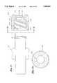
- FIG. 1is a cross-sectional view of a two-piece luer-lock connector and protector cap
- FIG. 2is a cross-sectional view of the two-piece luer-lock connector engaged with a female luer component and showing a hub in the distal, anti-rotation position;
- FIG. 4is an end elevational view of the two-piece luer-lock connector taken along line 4--4 of FIG. 3;
- FIG. 5is a partial plan view of a proximal end of the male luer component as seen along line 5--5 of FIG. 2;
- FIG. 6is an end elevational view of the male luer component taken along line 6--6 of FIG. 5;
- FIG. 7is an end elevational view of the hub of the two-piece luer-lock connector
- FIGS. 8a-8cshow several stages of engagement between friction surfaces of the hub and the male luer component
- FIG. 9is a perspective view of a preferred protector cap for the two-piece luer-lock connector
- FIG. 9ais an elevational view of an end of the protector cap taken along line 9a--9a of FIG. 9;
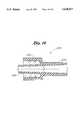
- FIG. 10is a cross-sectional view of another two-piece luer lock connector and protector cap embodiment
- FIG. 11is a detailed view of an area of engagement between a male luer component and rotatable hub shown in FIG. 10;
- FIG. 12ais a partial plan view of a proximal end of the male luer component showing a spline arrangement as seen along line 12--12 of FIG. 10;
- FIG. 12bis a partial plan view of a proximal end of the male luer component showing an alternative spline arrangement and taken along line 12--12 of FIG. 10;
- FIG. 13is a cross-sectional view of the interaction between the proximal end of the male luer component and the rotatable hub of FIG. 10;
- FIG. 14ais a cross-sectional view of a hub advancing distally over an alternative luer component
- FIG. 14bshows the hub advanced distally onto the male luer component of FIG. 14a
- FIG. 15is an exploded view of a female luer component and a protective cap therefor;
- FIG. 15ais an elevational view of the protective cap for the female luer component taken along 15a--15a of FIG. 15;
- FIG. 16is a cross-sectional view of a one-piece male luer component and hub
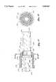
- FIG. 17is a cross-sectional view of a two-piece luer-lock connector having a hex coupling between the hub and male component;
- FIG. 18is a cross-sectional view of the hex coupling taken along line 18--18 of FIG. 17;
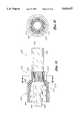
- FIG. 19is a cross-sectional view of a two-piece luer-lock connector having a ratchet coupling between the hub and male component;
- FIG. 20is a cross-sectional view of the ratchet coupling taken along line 20--20 of FIG. 19.
- FIG. 1is a cross-sectional view showing a two-piece medical luer-lock connector 20 engaged by a protector cap 22.
- the two-piece luer-lock connectorcomprises a hub 24 and a tubular male luer component 26.
- the hub 24is associated with a proximal component of a luer connector, the proximal direction being away from the patient or application site.
- One particularly useful application for the present inventionis for attaching an intravenous fluid supply line to an IV catheter at an infusion site.
- the male luer component 26comprises an elongate tubular body having a proximal tubular section 28, a tapered nose 30, and a tapered shoulder 32 disposed therebetween.
- a cylindrical step 33is provided on the tapered nose 30 just distal from the tapered shoulder 32.
- a central lumenconsists of a distal conduit 34 transitioning at a step 36 to a proximal conduit 38.
- the proximal conduit 38terminates in a flared mouth 40 for receiving a flexible delivery hose (not shown) which may be inserted all the way to the stop 36 and glued or otherwise adhered into place.
- the hub 24comprises a generally tubular sleeve having a proximal cylindrical exterior surface 42, a distal annular flange 44, and a series of axially extending grip rails 46, as best seen in FIG. 7.
- the hub 24has three distinct interior surface regions.
- a first distal regionincludes single or multiple internal threads 48.
- the internal threads 48may be standard ISO threads or may comprise helical grooves termed sometimes "oversized threads.”
- the proximal end of the distal regionterminates at an anti-rotational friction enhancing structure such as an annular internal ramp 50.
- a proximal regionincludes a plurality of radially, inwardly directed ribs 52 separated by channels 54. The functions of the internal surfaces of the hub 24 will be described more fully below.
- cap 22includes a plurality of end projections 56 which create a gap 58 (see FIG. 1) between the protector cap 22 and the male luer component 26 for ease of priming the device when the cap is in place, the small gap presenting a tortuous path for bacteria after sterilization.
- the protector cap 22is defined by a closed end portion 60 and an engagement tube portion 62 separated by an annular flange 64 which helps to prevent contamination of the tortuous path.
- An interior wall 66is tapered at approximately the same angle as the tapered nose 30 of the male component 26.
- the interior wall 66is formed with a draft of approximately 1° with respect to a central axis, while the nose 30 has a total taper of 0.060 in/in, which corresponds to an angle of 1.7° adjacent the interior wall 66.
- the outer diameter of the engagement tube 62is slightly greater than the inner diameter of the internal threads 48 of the hub 24.
- the end projections 56create the aforementioned gap 58 to allow the passage of sterilization gas or other media.
- the protector cap 22additionally has a plurality of axially extending grip rails 68 for facilitating the removal from the two-piece luer-lock connector 20.
- the hub 24is eliminated and an alternative protector cap is used which has a smaller internal diameter for interfering with the step 33 on the tapered nose 30.
- the inner circumference of the protective capmay have inwardly directed ribs for interfering with the step 33, or, the step 33 may be formed with a plurality of separate ribs for interfering with a continuous inner diameter of the protective cap.
- a small tortuous passageis provided through the inner lumen of the male component 26 and around the proximal end of the protective cap 22 by virtue of the end projections 56 and gap 58.
- the assembled male component 26 and protective cap 22can be sterilized allowing gases to flow therebetween.
- an open, yet highly tortuous pathis provided between the protective cap 22 and inner lumen of the male component 26. This tortuous path helps prevent contamination of the male luer component 26.
- Luer component 70may provide communication with a segment of IV line, medical device, infusion needle, or other structure as is understood in the art.
- the female luer component 70comprises a distal tubular portion 72 and larger diameter proximal tube 74 provided with one or more external thread segments 76.
- the external thread segments 76are sized and configured to threadingly mate with the internal threads 48 of the hub 24.
- the proximal tube 74has an inner lumen 78 which is tapered outwardly in the proximal direction.
- the taper angle of the wall of lumen 78preferably approximates the taper angle of the nose 30 of the male luer component 26.
- the tapered nose 30fits within the lumen 78 and the hub 24 threadingly engages the exterior thread segments 76 to lock the male and female luer components 26, 70 together in sealing engagement.
- the female luer component 70further includes a second lumen 82 within the distal tubular portion 72 and an inner throughhole 84 for providing communication between the first and second lumens 78, 82.
- the present luer-lock connectorcan provide for an anti-rotation feature for the hub 24 with respect to the male luer component 26. More specifically, as the hub 24 advances distally over the external thread segments 76, the engagement of the tapered shoulder 32 and internal ramp 50 causes the nose 30 to sealingly engage the first lumen 78. At some point, the engagement between the nose 30 and inner lumen 78 halts further distal movement of the male luer component 26. Further rotation of the hub 24 causes the cooperating ramped surfaces 32, 50 to slide axially relative to each other to produce a relatively tight friction fit between the hub 24 and friction enhancement surface 32.
- FIG. 8aillustrates a situation when the tapered engagement surfaces 32, 50 are in simple contact without substantial frictional engagement therebetween. This situation might be when the hub 24 has been sufficiently rotated to bring tapered nose 30 into contact with the inner lumen 78.
- an exterior step 86 of the male luer component 26 at the distal end of surface 32is disposed distally by a distance A from an internal step 88 of the hub 24 at the distal end of surface 50.
- FIG. 8billustrates a position wherein the hub 24 has been rotated further over the male luer component 26 causing the frictional engagement surfaces 32, 50 to slide axially relative to one another.
- the step 86is disposed a smaller distance B distally from the step 88 of the hub 24.
- the hub 24has been rotated farther over the exterior thread segment 76 of the female luer component 70 to force the frictional engagement surfaces 32, 50 to slide even more so relative to each other.
- the step 86is disposed proximally to the step 88 by a distance C.
- Further tightening of the hub 24will cause a hard stop 90 to contact a proximal stop surface 92 on the male luer component 26.
- the stop surfaces 90, 92may be disposed at approximately 45° angles to the longitudinal axis to prevent further relative axial movement and prevent fracture of either the male luer component 26 or hub 24 from overtightening.
- the hubis frictionally rotationally engaged with the male luer component 26.
- the present inventionprovides an anti-rotation friction throughout an axial range of travel in a manner that minimizes the risk of reverse rotation and loosening of the hub throughout various rotational positions of the hub 24.
- the relative axial position of the hub 24 with respect to the male luer component 26is determined by the amount of tightening torque applied thereto, which can differ from operator to operator.
- the present inventionaccommodates different application forces by providing an anti-rotation frictional engagement over a range of different tightening torques.
- the taper angles of the engagement surfaces 32, 50are thus selected to provide frictional engagement over a range of axial travel after the point at which the two surfaces initially contact.
- the shallower the taper anglesthe greater the axial travel that can be accomplished between the hub 24 and male luer component 26, within given elastic deformation limits of the hub 24.
- a relatively steep taper angle, such as is present for engaging thread surfaces,will tend to minimize the axial range of frictional engagement.
- the engagement surfaces 32, 50are preferably identically tapered within the range of from about 1% to about 15% with respect to the longitudinal axis of the tubular bodies.
- the engagement surfaces 32, 50are typically tapered less than about 10% and within a range of about 2% to about 8%, with a preferred range of between 2% to 6% and an optimum taper of about 5% with respect to the longitudinal axis of the tubular bodies.
- the axial travelis within the range of from about 0.08 and about 0.18 inches.
- the present two-piece luer lock connector 20provides an improved structure for rotationally locking the hub 24 to the male luer component 26.
- the radially inwardmost edges 53 of the radially inwardly extending ribs 52 on the hub 24define a circle having approximately the same diameter as the proximal tubular portion 28 of the male luer component 26.
- the proximal end of the male luer component 26includes a series of axially extending splines 94 projecting outward from the tubular portion 28.
- the ribs 52are dimensioned to interfit in sliding engagement between the splines 94 along guideways 96.
- the splines 94extend along the channels 54 between the ribs 52.
- the circumferential dimensions of the ribs 52 and guideways 96may provide a slight interference tolerance to indicate when the hub 24 and male luer component 26 are rotationally locked.
- the male luer component 26includes at least a central axially elongated spline 94a, preferably also a pair of intermediate splines 94b disposed on either side of the central spline, and most preferably also a third pair of substantially diametrically opposed splines 94c.
- the distal end of the central spline 94aincludes a point 98 leading to a pair of ramped cam surfaces 100.
- the proximal end of the elongated spline 94ais preferably tapered radially inwardly in the proximal direction and also tapered circumferentially to produce a point 102.
- the second and third pairs of splines 94b, 94cform generally rectangular radial projections with the second splines 94b including angled edges 104 facilitating removal of a forming mold.
- the male luer component 26is preferably formed by two mating semi-cylindrical half-molds with all of the splines 94 being formed by only one of the two molds. In the illustrated embodiment of FIG. 6, the upper mold would form the splines 94 and thus it can be readily seen that the edges 104 allow the mold to be lifted off cleanly.
- the present inventionmay comprise only one spline 94.
- the preferred embodimentincludes splines 94 on only one circumferential half, it should be noted that splines may be formed all the way around the circumference of the male luer component 26 and still achieve many of the inventive aspects herein.
- a circumferentially formed "speed bump” or ridge 106is provided on the male luer component 26.
- the illustrated circumferential ridge 106is centered at the elongated spline 94a although it can readily be positioned at other locations around the circumference of tubular body 28 or be formed in a 360° circle to act as a retaining ring.
- the illustrated ridge 106extends circumferentially in an approximately 90° arc around the tubular portion 28 and has a radially projected height of at least one-half and preferably nearly two-thirds the height of the splines 94.
- the circumferential ridge 106is preferably formed with an apex 106a and a pair of ramped surfaces 106b. As the hub 24 is advanced in the proximal direction, the inwardly directed ribs 52 come in contact with the circumferential ridge 106 and the user experiences a more pronounced drag or frictional engagement between the hub 24 and male luer component 26.
- the size of the ridge 106 and the preferred connector materialallow the hub 24 to be advanced across the ridge and flex without damage to either component. In some cases, extreme tolerances may create an additional interference between the inwardly directed ribs 52 and circumferential ridge 106.
- the ribs 52may shave off or deform a small portion of the ridge 106 resulting in a consistent interference and tactile feedback thereafter.
- the purpose of the ridge 106is to provide feedback to indicate to an operator when the hub 24 is axially positioned to achieve optimum rotational locking engagement with the male luer component 26.
- the diameters of the inwardly directed ribs 52 and proximal tubular portion 28may be such that there is a net tolerance in the region of the splines 94 to provide this tactile feedback, instead of providing a circumferential ridge 106.
- FIG. 12billustrates a "keyed" version wherein a stepped spline positively stops the hub in a position coupling the hub and male component. The hub may be removed by rotation with respect to the male component.
- Other tactile feedback structures for indicating the axial position of the hub 24can be readily envisioned by one of skill in the art in view of the disclosure herein.
- the hub 24can be completely removed from the proximal end of the male luer component 26.
- the hub 24can thus be slid proximally along a supply line (not shown) to remove it from the immediate connector site. This may be advantageous in neo-natal, pediatric or other applications where the relatively large diameter of the hub 24 is an impediment to proper positioning of the connector and associated medical components, and may cause a pressure point on the skin.
- the cam surfaces 100 on the distal end of the elongated central spline 94aensure the proper rotational registry of the hub 24 with the splines 94.
- the proximal ends of the ribs 52are tapered at 108 to form guide points.
- the distal point 98 on the central spline 94awill initially contact the inwardly directed ribs 52.
- the ribs 52may either be aligned with the channels 96 or with the central elongated spline 94a. In the latter case, the guide points 108 will contact one or the other of the cam surfaces 100 on either side of the proximal point 98, and the hub 24 will be caused to rotate into proper rib/spline alignment.
- distal travel of the hub 24 onto the male component 26may initially bring point 102 into contact with a corresponding point on the distal end of one of the ribs 52. Further distal advancement of the hub 24 will cause an appropriate rotational alignment of the ribs 52 with channels 96.
- the male component 26has an overall length of about 1.12 inches, with an outside diameter of the proximal tubular portion 28 being approximately 0.236 inches.
- the step 86 on the tapered shoulderbegins at approximately 0.435 inches from the distal tip of the tubular body 26 and the tapered surface 32 has an axial length of approximately 0.065 inches.
- the small diameter on the proximal end of the tapered step 32is approximately 0.269 inches, while the large diameter is approximately 0.275 inches of the hub 24.
- hub 24has an overall length of approximately 0.54 inches, and the inwardly directed ribs 52 define a cylinder having a diameter of approximately 0.240 inches, resulting in a about 0.004-inch nominal clearance between the ribs and the proximal tubular portion 28.
- the annular inclined surface 50 on the hub 24preferably has an axial length of approximately 0.088 inches, a small diameter of approximately 0.266 inches, and a large diameter of approximately 0.279 inches.
- the ribs 52may have an axial length of approximately 0.127 inches, while the axial length of the intermediate and diametrically opposed splines 94b, 94c have an axial length of about 0.123 inches.
- the central spline 94ahas an axial length from distal point 98 to proximal point 102 of approximately 0.223 inches.
- the circumferential ridge 106preferably extends 90° around the male tubular portion 28 and has a radial height of approximately 0.008 inches at its apex 106a.
- the hub 24has a preferred nominal wall thickness of approximately 0.039 inches, while the male luer component 26 has a minimum wall thickness in the proximal tubular portion 28 of approximately 0.047 inches.
- the components of the two-piece luer connector 20are preferably injection molded using known biocompatible materials. More specifically, the materials are preferably resistant to corrosion from chemicals, such as alcohol and/or lipids, common in medical environments.
- ABSavailable from BASF under the trade name TERLUXTM
- acrylic, polycarbonate or other materialfor the male and female components 26, 70.
- Polypropyleneis used for the protector cap 22 to allow for deformation from the tolerance interference with the male luer component 26 during assembly and to enhance resistance therebetween, preventing the cap from falling off.
- the materials used for the male component 26 and hub 24are preferably dissimilar to enhance the frictional engagement between the surfaces 32, 50.
- the hub 24 and male luer component 26may be provided with a ratchet-type engagement.
- either the hub 24 or male luer component 26is provided with one or more detents, which engage grooves in the opposite component to securely lock the hub relative to the male luer component.
- a ratchet configurationis shown and described with reference to FIGS. 19 and 20.
- Other types of complementary surface structurescan be readily provided which, through elastic deformation during tightening, provide a relatively high resistance to reverse hub rotation.
- the nose 30 of the male luer component 26is inserted within the tapered lumen of the female luer component 70.
- the hub 24is advanced in a distal direction so as to engage the inwardly extending threads 48 with the external thread segments 76.
- the hub 24is then rotated relative to both the male and female components 26, 70 to advance over the external thread segments 76 without applying a torque to any hoses connected to the male and female components.
- the tapered nose 30will be forced into sealing engagement with the lumen 78 and the male luer component 26 will experience resistance to further advancement into the female luer component 70.
- the hub 24may be advanced a short distance further causing the tapered engagement surfaces 32, 50 to slide relative to each other, as previously described.
- the male and female luer connectors 26, 70are firmly attached, and the hub 24 is frictionally rotationally engaged on the tapered annular shoulder 32.
- the operatorgrasps the wings 80 or other structure of the female luer component 70 and rotates the hub to disengage the engagement surfaces 32, 50 and reverse the internal threads 48 from the external thread segments 76.
- the amount of torque required to remove the hub 24is sufficient to minimize the risk of inadvertent hub rotation, and may in some embodiments be even slightly greater than the torque applied in tightening. This is due to the greater coefficient of static friction between the tapered engaging surfaces 32, 50 achieved by the present invention than their relative coefficient of sliding friction.
- the hub 24After untightening of the hub 24 from the surface 32 of the male luer component 26, the hub is in a position enabling it to be freely rotated with respect to the male luer component. Although not shown, this position is somewhere between the illustrations of FIGS. 2 and 3, with the ribs 52 between the tapered shoulder 32 and the splines 94. In a more proximal position of the hub 24, the axial ribs 52 are in registry with the splines 94 to rotationally lock the hub with respect to the male luer component 26. The larger diameter hub 24 increases the torque available to unlock the male luer component 26 from frictional engagement with the female luer component 70. This is shown in FIG. 3. Finally, as described above, the hub 24 may be retracted in a proximal direction completely from the male luer component 26 in a still further position along the fluid conduit.
- FIGS. 9 and 9aillustrate an alternative protective cap 22' which includes a series of outwardly directed ribs 110 on the cylindrical engagement portion 62.
- the ribs 110are provided to engage the inwardly directed threads on the hub of the present luer connector. This engagement is illustrated in FIG. 10, as will be described below.
- the ribs 110extend from the annular flange 64 toward a proximal open end 112 and terminate at ramped surfaces 114.
- the ribs 110are preferably rounded in cross-section. It has been recognized that the material of the protector cap 22', preferably polyethylene, shrinks during exposure to the sterilization environment.
- the materials of the male luer connector and hubare less susceptible to dimensional changes during sterilization.
- an interference fit provided between a smooth engagement portion 62 and inwardly directed threads 48 prior to sterilizationleads to a relatively loose fit after sterilization.
- attempts to solve this problem by increasing the diameter of the tubular portion 62prevents initial engagement between the protective cap 22 and hub 24.
- the present inventioncontemplates providing the axially directed ribs 110 to allow for an increased initial interference fit between the ribs and the inwardly directed threads of the hub.
- the protective cap 22'has undergone some shrinkage, but the ribs 110 still provide a sufficient frictional engagement with the inwardly directed threads of the hub to retain the protective cap over the nose of the male luer component.
- FIG. 10is a cross-sectional view showing an alternative two-piece medical luer lock connector 120 engaged by the aforementioned protector cap 22'.
- the two-piece luer lock connector 120comprises a hub 124 and a tubular male luer component 126.
- the male luer component 126comprises an elongate tubular body having a proximal tubular section 128, a tapered nose 130, and a tapered shoulder 132 disposed therebetween.
- a central lumenconsists of a distal conduit 134, a larger proximal conduit 136, and a step 138 disposed therebetween.
- the proximal conduit 136terminates in a flared mouth 140 for receiving a flexible delivery hose (not shown) which may be inserted all the way to the step 138 and glued or otherwise adhered into place.
- the hub 124comprises a generally tubular sleeve having a proximal cylindrical surface 142, a distal annular flange 144, and a series of axially extending short and long grip rails 146a, 146b.
- the hub 124includes three distinct interior surface regions.
- the first distal interior regionhas single or multiple internal threads 148.
- the internal threads 148are preferably standard ISO threads.
- a proximal end of the distal interior regionterminates at an anti-rotational friction enhancing structure such as an annular internal taper 150.
- a proximal interior region of the hub 124includes a plurality of radially inwardly directed ribs 152 separated by channels 154 (see FIG. 13). The functions of the internal surfaces of the hub 124 will be described more fully below.
- the two-piece luer-lock connector 120is provided prior to use with the protective cap 22'.
- the outwardly directed ribs 110 on the protective cap 22'engage with the inwardly directed threads 148 on the hub 124.
- the slight interferenceprovides a gripping force thus preventing the protective cap 22 from sliding from within the hub 124.
- the present inventionhas been designed to provide a consistent grip between the protective cap 22' and hub 124. More particularly, the threads 148 have a predetermined pitch, and the ribs 110 a predetermined length, so that each rib contacts two of the threads at all times. This results in a eight points of contact between the protective cap 22' and the hub 124 in any rotational orientation therebetween.
- an outer cylindrical step 156 on the tubular nose 130frictionally engages an inner diameter of an alternative protective cap (not shown). This frictional engagement is utilized when the hub 124 is not present.
- the two-piece luer-lock connector 120is adapted to couple to a second tubular body, such as the female luer component 70 shown in FIG. 2.
- a second tubular bodysuch as the female luer component 70 shown in FIG. 2.
- the protective cap 22'is removed and the nose 130 of the male luer component 126 inserted within a similarly tapered proximal tube on the female luer component.
- the hub 124may be used to axially engage the male luer component 126 with the female luer component.
- the inwardly directed ribs 152have angled distal surfaces 158 which engage with angled steps 160 on the exterior of the male luer component 126, disposed distally from the tapered shoulder 132.
- the hub 124engages the angled surfaces 158 and 160 to prevent the hub 124 from sliding in a distal direction relative to the male luer component 126.
- the hubis used to displace the male luer component 126 toward the female luer component.
- the tapered nose 130is engaged within the internal taper of the female luer component.
- the hub 124may be utilized to lock the two components together, or may be removed.
- the female luer componentis provided with one or more external thread segments, such as those shown at 76 in FIG. 2.
- the thread segmentsare sized and configured to mate with the internal threads 148 of the hub 124.
- the hub 124rotates freely over the coupled male and female luer components to advance the internal threads 148 over the external threads of the female luer component.
- the angled distal surfaces of the ribs 152contacts the angled step 160 on the exterior of the male luer component 126.
- the nose 130is forced into the tapered inner tubular portion of the female luer component.
- the frictional engagement between the angled surfaces 158, 160provides a slight antirotation feature for the hub 124 with respect to the male luer component 126. More specifically, the surfaces 158, 160 are preferably angled within the range of about 30° to 60°, and preferably approximately 45°, and undergo a small frictional engagement upon tightening of the hub 124. This minimal frictional engagement helps prevent the hub 124 from coming loose.
- the male luer component 126is also provided with the tapered shoulder 132 at a relatively shallow angle with respect to a central axis to couple with the first-described hub 24.
- the angle of the tapered shoulder 132is preferably within the range of 0.5° to 7°.
- the male luer component 126is adapted to receive the hub 24. More particularly, the inner frictional engagement surface 50 of the hub 24 is sized to engage the outer tapered shoulder 132 of the male luer component 126.
- the aforementioned frictional engagementhaving a range of axial travel of the hub 24 over the male luer component 126 is provided.
- the two-piece luer lock connector 120includes structure for rotationally locking the hub 124 to the male luer component 126.
- the radially inner edges 153 of the ribs 152define a circle have approximately the same diameter as the proximal tubular portion 128 of the male luer component 126.
- the proximal end of the male luer component 126includes a series of axially extending splines 164 projecting outward from the tubular portion 128.
- the ribs 152are dimensioned to interfit in sliding engagement between the splines 164 along guideways 166. Conversely, the splines 164 extend along the channels 154 between the ribs 152.
- the circumferential dimensions of the ribs 152 and guideways 166may provide a slight interference tolerance to indicate when the hub 124 and male luer component 126 are rotationally coupled.
- a separate circumferential ridge, or "speed bump,” as described below,is provided.
- the male luer component 126includes at least a central axially elongate spline 164a along its exterior surface, and preferably also includes a first pair of intermediate splines 164b disposed on either side of the central spline. Furthermore, a second pair of substantially diametrically opposed splines 164c is also provided.
- the distal end of the central spline 164aterminates in a point 168 between a pair of ramped cam surfaces 170.
- the proximal end of the elongate spline 164ais preferably tapered radially inwardly in the proximal direction, and also tapered circumferentially to result in a pointed ramp 172.
- the first and second pairs of splines 164b and 164cform generally rectangular radial projections with the intermediate splines 164b including angled edges 174 facilitating removal of a forming mold.
- the male luer component 126is preferably formed by two mating semi-cylindrical half-molds with all of the splines 164 being formed by only one of the two molds.
- the upper moldwould form the ridges 164 and it can be readily seen that the edges 174 allow the mold to be lifted off cleanly.
- This arrangementincreases the potential mold cavity density in the manufacturing molds. Specifically, the elimination of certain slides used to form undercuts allows the mold cavity density to increase from 32 or 48 cavities per mold to 64 cavities per mold. Each cavity forms an individual part in each mold. It will be readily apparent to one of skill in the art that the increased mold cavity density by a factor of two greatly speeds the manufacturing process, and reduces the expense associated with manufacturing the molds.
- spline contact points 177there are at least three spline contact points 177 in either rotational sense to provide tangential strength to avoid stripping the splines 164 by the inwardly directed ribs 152.
- the present inventionmay comprise only one spline 164.
- the preferred embodimentincludes splines 164 on only one circumferential half, it should be noted that splines may be formed all the way around the circumference of the male luer component 126 and still exhibit many of the inventive aspects herein.
- Tactile feedback for an operator when sliding the hub 124 axially in a proximal direction into the rotationally locked positionis provided by a circumferentially formed ridge 176 on the male luer component 126.
- the circumferential ridge 176is centered at the elongated spline 164a, although it can be readily positioned at other locations around the circumference of the tubular body 128, or be formed in a 360° circle to act as a retaining ring.
- the illustrated ridge 176extends circumferentially in an approximately 90° arc around the tubular portion 128 and has a radially projected height of at least one half and preferably approximately two-thirds the height of the splines 164.
- the circumferential ridge 176 seen in FIG. 12ais formed with a flat apex 176a and a pair of outer ramped surfaces 176b.
- the inwardly directed ribs 152come into contact with the circumferential ridge 176 and the user experiences a more pronounced drag or frictional engagement between the hub 124 and male luer component 126 due to the increased surface area contact therebetween.
- the height of the ridge 176 and the preferred connector materialallow the hub 124 to advance across the ridge and flex without damage to either component.
- the ribs 152may shave off or deform a small portion of the ridge 176, in cases of extreme tolerance interference, resulting in a consistent tactile feedback thereafter.
- the ridge 176provides tactile feedback to an operator to indicate when the hub 124 is axially positioned to achieve optimum rotational locking engagement with the male luer component 126. As mentioned previously, other tactile feedback structure to indicate this preferred axial position of the hub 124 over the male luer component 126 is contemplated.
- the ribs 152are narrower than the previously described ribs 52.
- the radially inward points 153 in contact with the male luer component 126are thus narrower.
- the narrower ribs 152facilitate automated assembly of the hub 124 onto the male luer component 126. It has been discovered through empirical tests that the narrower ribs 152 allow for some rotational movement between the hub 124 and the male luer component 126. Because of this rotational looseness, the ribs 152 may not travel over the same circumferential location of the circumferential ridge 176 every time the hub 124 is reversed proximally over the male luer component 126.
- the splines 164a, b, chave been widened in the circumferential direction to provide narrower guideways 166.
- the tubular portion 128has a diameter of approximately 0.236 inches
- the central spline 164ahas a circumferential width of approximately 0.070 inches
- the splines 164bhave an effective circumferential width of approximately 0.035 inches
- the tapered ribs 152are spaced apart 0.080 inches at their bases.
- the wider splines 164cause the ribs 152 to travel across the same location on the circumferential ridge 176 every time the hub 124 is displaced into rotational engagement with the male luer component 126. Furthermore, the flat 176a formed on the apex of the ridge 176 reduces wear of the ridge thus further ensuring a consistent tactile feedback for the operator.
- the hub 124can be completely removed from the proximal end of the male luer component 126. As described previously, the hub 124 can be slid proximally along a supply line (not shown) to remove it from the immediate connector site.
- the cam surfaces 170 on the distal end of the elongate central spline 164aensure the proper rotational registry of the hub 124 with the splines 164.
- the proximal end of the ribs 152are tapered at 178 to form guide points. As the hub 124 is slide proximally along the male luer component 126, the distal point 168 on the central spline 164a will initially contact the inwardly directed rib 152.
- the ribs 152may either be aligned with the channels 166 or with the central elongate spline 164a.
- the guide points 178will contact one or the other of the cam surfaces 170 on either side of the proximal point 168, and the hub 124 will be caused to rotate into proper rib/spline alignment.
- distal travel of the hub 124 onto the male component 126may initially bring point 172 into contact with the distal end of one of the ribs 152. Further distal advancement of the hub 124 will cause an appropriate rotational alignment of the ribs 152 into channel 166.
- a positive stopmay be provided to temporarily prevent the hub 124 from being removed in a proximal direction from the male luer component 126.
- a central "keyed" spline 200may be provided in place of either the spline 94a or 164a.
- the spline 200is defined by a central constant width portion 202, a proximal arrowhead portion 204, and a distal arrowhead portion 206. Projections of pairs of adjacent ribs 152 are illustrated in FIG. 12b. That is, the radially inward surfaces 153 of the ribs 152 are projected on the male luer component 126.
- the ribs 152are disposed proximate the distal arrowhead portion 206.
- the spacing between the ribs 152is slightly greater than the circumferential width of the distal arrowhead portion 206.
- the arrowhead portion 206is provided with an apex and a pair of adjacent cam surfaces to guide the ribs 152 therearound.
- a second position Bthe ribs have advanced proximally to lie adjacent the central constant width portion 202 and within the guideways 166.
- a proximal end of one of the ribsis prevented from further proximal movement by a stop surface 208 formed on the proximal arrowhead portion 204. Further proximal movement of the hub 124 is prevented.
- the hubis rotated, as with turning a key, to place the ribs 152 in the position C. From the position C, the hub may be translated proximally so that the ribs are in the position D, and the hub may be removed completely.
- the proximal arrowhead portion 204is sized slightly smaller than the spacing between the ribs 152.
- the ribsare guided around the proximal arrowhead portion 204 by its taper, and then automatically around the distal arrowhead portion 206 by virtue of an angled surface 210 provided thereon.
- the stop surface 208provides a positive tactile feedback indicating to the operator that the hub 124 is in an axial position in which it is rotationally locked with respect to the male luer component 126.
- FIG. 12beliminates the need for a circumferential "speed bump," but it will be appreciated that one may be provided for redundancy.
- one or more small bumps 211are preferably formed on the exterior of the male luer component 126 between at least two of the splines, in this case shown between the central constant width portion 202 of the spline 200 and the adjacent intermediate splines.
- the ribs 152interfere with these bumps 211 so that the hub 124 must be forced thereover when rotated before being displaced proximally from the male component 126. This provides tactile feedback to the user indicating the rotational position of the hub 124.
- a circumferential ridge or other such structuremay be provided on the male luer component 126 to allow the hub 124 to be advanced distally thereon, but prevent the hub from being removed proximally.
- a circumferential retaining ring 220is illustrated projecting from the tubular portion 128 of the male luer component 126.
- the hub 124advances in a distal direction as seen by the arrows 222.
- Diametrically opposed axial slits 224 provided in the proximal end of the male luer component 126allow a slight inward flexing at that location when the ribs 152 cam over the retaining ring 220.
- FIG. 14billustrates the hub 124 after having been "snapped" over the retaining ring 220 and advanced distally onto the male luer component 126.
- the proximal end of the male luer component 126has resiliently recovered into its original position. Reversing the direction of the hub 124 in a proximal direction over the male luer component 126 causes a rear edge 226 to come into contact with the retaining ring 220.
- the hub 124is retained on the male luer component 126.
- the retaining ring 220is rounded or angled and the hub 142 can be removed from the proximal end of the male luer component 124 with the application of sufficient force.
- other embodiments rigidly preventing removal of the hub 124 in this mannerare contemplated.
- FIGS. 15 and 15aillustrate a preferred protective cap 230 for the female luer component 70 described with reference to FIGS. 1-8.
- the female luer component 70is provided with external threads 76.
- the protective cap 230includes inner threads 232 sized and shaped to mate with the threads 76.
- the cap 230includes dual threads 232a and 232b.
- the cap 230is advanced over the female luer component 70 until a distal end 234 of the female component contacts a plurality of radially oriented bumpers 236 provided on the interior of a closed end 238 of the cap 230.
- the bumpers 236function in a similar manner as the projections 56 on the end of the protective cap 22 for the male luer component.
- the bumpers 236provide a small gap between the protective cap 230 and the female luer component 70 to facilitate sterilization while the cap is in place.
- the female luer component 70can thus "breathe” with the cap 230 installed while providing a tortuous path to prevent contamination of the fluid pathway.
- the bumpers 236may be eliminated for a "non-breather” type of cap 230.
- the proximal end of the female luer component 70forms a seal with the interior of the closed end 238 of the cap 230.
- the cap 230also incorporates dual helical "crush threads" 240a, 240b formed adjacent the threads 232a, b.
- the crush threads 240a, bextend radially inward to interfere with the major diameter of the female luer component threads 76.
- the interferencecreates a frictional fit between the cap 230 and female luer component 70 preventing inadvertent decoupling.
- the major diameter of the female luer component threads 76is approximately 0.306 inches
- the inner diameter of the crush threads 240a, bis approximately 0.300 inches, resulting in an interference of 0.006 inches. This will yield a frictional torque resisting decoupling of the cap 230 of approximately 70.0 oz-in.
- the crush threads 240a, bare only formed on the last half-turn of the inner threads 232a, b with sufficient length to run past the major diameter of the female thread 76 to prevent compression and a possible set from occuring during sterilization.
- the crush threads 240a, bare desirably disposed approximately 180° apart to prevent "cocking" of the protective cap 230 when threaded over the female luer component 70.
- Previous attempts at creating an interference between a protective cap and female componentconsisted of sizing the inner thread diameter smaller. Since the cap is often hard to assemble on the end of the female component due to tolerance extremes, fatigue of the assembler may result.
- the embodiment illustrated in FIGS. 15 and 15aallows the threads on the cap 230 to be sized to fit easily over the female component even after shrinkage, and the crush threads 240 provide an interference during the latter part of the assembly.
- the crush threads 240a, bare contemplated.
- the threads 232a, bmay be dimensionally altered or may have a varying pitch toward the closed end 238 of the cap 230.
- the threads 240a, bmay also be replaced with discrete bumps or other protrusions which interfere with the female threads 76. In all of these variations, the frictional interference is maintained after sterilization and only comes into effect after the cap 230 has been substantially threaded onto the female component 70.
- the material of the cap 230is soft enough to allow deformation of the crush threads 240a, b, but will not deform the exterior threads 76 of the female luer component 70.
- the material of the cap 230is preferably polyethylene, while the female luer component 70 is acrylic, or other alcohol and/or lipid resistant material.
- FIG. 16illustrates a one-piece hub/male luer component 250.
- a hub portion 252is formed integrally with a male luer portion 254.
- the one-piece component 250is often desirable. In particular, in small tubing (conduit) applications.
- the one-piece component 250facilitates axial engagement of the tapered nose 256 with the inner taper on a female luer component. If desired, the inner threads on the hub portion 252 can engage the threads on the female luer component to lock the connector together.
- FIGS. 17 and 18Another type of anti-rotation structure between a male luer component 260 and an outer hub 262 is seen in FIGS. 17 and 18.
- the male component 260comprises a distal nose portion 264, a proximal hose-receiving tube 266, and a cylindrical flange 268 therebetween.
- An inner lumenis defined by three passages increasing in size from the distal end to proximal end. More particularly, the lumen includes a distal first passage 270a, and second passage 270b, and a third passage 270c.
- Two transition regions 272a, 272bprovided hose stops between the first and second passages 270a, b and between the second and third passages 270b, c, respectively.
- the hub 262has a generally cylindrical sleeve portion 274 with a circular lip 276 extending radially inward at a proximal end.
- the lip 276includes a polygonal inner edge 278, preferably formed as a dodecahedron with 12 sides, which mates with a polygonal exterior portion 280, preferably formed as a hexagon, on the male component 260 adjacent to the flange 268 in the proximal direction.
- the polygonal inner edge 278includes parallel sides spaced apart a distance less than the outer diameter of the flange 268.
- the hub 262can thus be used to axially displace the male component 260 into engagement with a female component (not shown) to form a luer connection.
- the hub 262rotationally couples with the male component 260 at the polygonal inner edge 278 and polygonal exterior portion 280.
- tight fits between the nose portion 264 and tapered lumen of the female componentmay be broken more easily by rotating the hub 262 with respect to the wings of the female component.
- FIGS. 19 and 20illustrate a coupling between a hub 290 and a male luer component 292 which prevents relative rotation in one direction yet allows limited relative rotation in the other direction. More specifically, the hub 290 may advance the male luer component 292 onto a female luer component, whereupon the hub can rotate freely relative to the male component without causing the male luer to twist.
- the male component 292comprises a tubular hose-receiving portion 294 having exterior ratchet splines 296 thereon, a tapered shoulder 298 and a distal nose 300.
- a central stepped lumen 302extends through the male component 292.
- the hub 290is defined by a sleeve-like portion 304 having internal threads 306, a proximal region 308 having a plurality of cantilevered fingers 310 separated by axial gaps 312, and a transition region 313 with an internal taper 314.
- the fingers 310are distributed around and extend proximally from the transition region 313 to form a plurality of curved cantilevered beams surrounding the tubular portion 294 of the male component 292.
- each finger 310defines at least two and preferably three axially aligned teeth 316 sized and shaped to mate with the splines 296.
- the teeth 316 and splinesare so configured to allow the fingers 310 to cam over the splines when the hub 290 rotates with respect to the male component 292 in a clockwise direction as viewed from the perspective of FIG. 20. This rotation corresponds to the direction for advancing the threads 306 onto the female component.
- the resiliency of the fingers 310is great enough to withstand relative hub/male component rotation, however, below a certain relative torque threshold.
- the male component 292is rotated along with the hub 292 as the hub advances on the female component by virtue of the interference between the tapered shoulder 298 and internal taper 314 until the nose 300 is firmly lodged in a tapered lumen.
- the hub 290"skips" over the male component and the teeth 316 make an audible clicking sound as they cam over the splines 296.
- twisting of the luer connectionis prevented during assembly of a male component to a female component. Overtightening is prevented by the interference between the 45° of the tapered shoulder 298 and internal taper 314.
- Reverse rotation of the hub 290 with respect to the male component 292is prevented by the specific shape of the spline/teeth interface, so that the luer connection remains secure despite vibration or inadvertent jostling.
- the luer connectionis broken by forced rotation of the hub 290 in a counter-clockwise direction while holding firm the female component wings.
Landscapes
- Health & Medical Sciences (AREA)
- Heart & Thoracic Surgery (AREA)
- Pulmonology (AREA)
- Engineering & Computer Science (AREA)
- Anesthesiology (AREA)
- Biomedical Technology (AREA)
- Hematology (AREA)
- Life Sciences & Earth Sciences (AREA)
- Animal Behavior & Ethology (AREA)
- General Health & Medical Sciences (AREA)
- Public Health (AREA)
- Veterinary Medicine (AREA)
- Infusion, Injection, And Reservoir Apparatuses (AREA)
Abstract
Description
TABLE 1 __________________________________________________________________________Comparative Disassembly Torques for Luer Hubs (in.-oz.) Company Baxter Baxter t Abbott Abbott (new) (old) Borla IVAC Siemens n)d __________________________________________________________________________1 13 10 5.5 5.5 8 9.5 65 2 11 9.5 5 5.5 8.5 10 5.5 3 11 9.5 5.5 5.5 9 11.5 4.5 4 11 9 5.5 4.5 8 11 7 5 10.5 7 5.5 5.5 8 20 6.55 5 Total 56.5 45 27 26.5 41.5 62 29.58 Average 11.3 9 5.4 5.3 8.3 12.4 5.98 __________________________________________________________________________
Claims (32)
Priority Applications (6)
| Application Number | Priority Date | Filing Date | Title |
|---|---|---|---|
| US08/431,073US5620427A (en) | 1995-04-27 | 1995-04-27 | Luer lock system |
| CA 2219211CA2219211A1 (en) | 1995-04-27 | 1996-04-26 | Luer lock system |
| DE1996630462DE69630462T2 (en) | 1995-04-27 | 1996-04-26 | Luer connection system |
| PCT/US1996/005772WO1996033762A1 (en) | 1995-04-27 | 1996-04-26 | Luer lock system |
| EP19960913156EP0869826B1 (en) | 1995-04-27 | 1996-04-26 | Luer lock system |
| US08/834,090US6152913A (en) | 1995-04-27 | 1997-04-14 | Medical luer connection having protective cap with crush rib |
Applications Claiming Priority (1)
| Application Number | Priority Date | Filing Date | Title |
|---|---|---|---|
| US08/431,073US5620427A (en) | 1995-04-27 | 1995-04-27 | Luer lock system |
Related Child Applications (1)
| Application Number | Title | Priority Date | Filing Date |
|---|---|---|---|
| US08/834,090Continuation-In-PartUS6152913A (en) | 1995-04-27 | 1997-04-14 | Medical luer connection having protective cap with crush rib |
Publications (1)
| Publication Number | Publication Date |
|---|---|
| US5620427Atrue US5620427A (en) | 1997-04-15 |
Family
ID=23710331
Family Applications (2)
| Application Number | Title | Priority Date | Filing Date |
|---|---|---|---|
| US08/431,073Expired - LifetimeUS5620427A (en) | 1995-04-27 | 1995-04-27 | Luer lock system |
| US08/834,090Expired - LifetimeUS6152913A (en) | 1995-04-27 | 1997-04-14 | Medical luer connection having protective cap with crush rib |
Family Applications After (1)
| Application Number | Title | Priority Date | Filing Date |
|---|---|---|---|
| US08/834,090Expired - LifetimeUS6152913A (en) | 1995-04-27 | 1997-04-14 | Medical luer connection having protective cap with crush rib |
Country Status (5)
| Country | Link |
|---|---|
| US (2) | US5620427A (en) |
| EP (1) | EP0869826B1 (en) |
| CA (1) | CA2219211A1 (en) |
| DE (1) | DE69630462T2 (en) |
| WO (1) | WO1996033762A1 (en) |
Cited By (186)
| Publication number | Priority date | Publication date | Assignee | Title |
|---|---|---|---|---|
| US5860962A (en)* | 1997-12-08 | 1999-01-19 | Becton, Dickinson And Company | Shielded cannula for use with an I.V. site |
| WO1999037356A1 (en)* | 1998-01-21 | 1999-07-29 | Joseph Lennox Peters | Couplings for medical cannulae |
| US5984373A (en)* | 1998-03-12 | 1999-11-16 | Elcam Plastic Kibbutz Bar-Am | Luer connector |
| US5988700A (en)* | 1995-12-13 | 1999-11-23 | Sherwood Services A G | Leak proof tube connection site |
| US6096011A (en)* | 1998-01-29 | 2000-08-01 | Medrad, Inc. | Aseptic connector and fluid delivery system using such an aseptic connector |
| USD435652S (en)* | 1999-03-30 | 2000-12-26 | Alcon Laboratories, Inc. | Shielded female connector |
| US6221064B1 (en)* | 1998-07-27 | 2001-04-24 | B. Braun Celsa | Tube coupling device for connecting a tubular rigid stem to a flexible catheter tube |
| US6228049B1 (en) | 1996-02-09 | 2001-05-08 | Promex, Inc. | Surgical and pharmaceutical site access guide and methods |
| US20010031221A1 (en)* | 1997-12-17 | 2001-10-18 | Wu Su-Syin S. | Apparatus and method for delivering fluids to contact surfaces between parts of a medical device |
| WO2001091847A2 (en) | 2000-06-01 | 2001-12-06 | Venetec International, Inc. | Anchoring system for luer lock connector |
| US6332633B1 (en) | 1999-12-15 | 2001-12-25 | Elcam Plastic Kibbutz Bar-Am | Luer-type connector |
| EP1181946A1 (en)* | 2000-08-04 | 2002-02-27 | Alan David Mogg | Catheter adapter |
| US6402207B1 (en) | 1997-06-09 | 2002-06-11 | Qd Enterprises, Llc | Safety indexed medical connectors |
| EP1236481A1 (en)* | 2001-02-16 | 2002-09-04 | Industrie Borla SpA | Male luer-lock connector for medical fluid lines |
| WO2002096500A1 (en)* | 2001-05-31 | 2002-12-05 | B. Braun Melsungen Ag | Patient safety connector |
| US6500153B1 (en) | 2001-07-13 | 2002-12-31 | Children's And Women's Health Centre Of British Columbia | Syringe and needle for preventing inadvertent drug injection |
| US20030026729A1 (en)* | 1997-08-21 | 2003-02-06 | Wu Su-Syin S. | Lumen sterilization device and method |
| US20030070490A1 (en)* | 2001-10-09 | 2003-04-17 | Toyoda Koki Kabushiki Kaisha | Pressure detection device |
| US6569118B2 (en)* | 2000-05-25 | 2003-05-27 | Johnnie M. Johnson | Adapter and method of attachment for “LUER LOK” receptacles |
| US6595964B2 (en) | 2000-12-22 | 2003-07-22 | Baxter International Inc. | Luer activated thread coupler |
| US6605075B1 (en)* | 1999-12-21 | 2003-08-12 | Ethicon, Inc. | Flushable hub |
| US20030151256A1 (en)* | 2002-02-08 | 2003-08-14 | Industrie Borla Spa | Male luer lock connector for medical fluid lines |
| US20030153865A1 (en)* | 2002-02-11 | 2003-08-14 | Brian Connell | Dialysis connector and cap having an integral disinfectant |
| US20030184090A1 (en)* | 2002-03-27 | 2003-10-02 | Industrie Borla S.P.A. | Male luer lock conncector for medical fluid lines |
| US20040039341A1 (en)* | 2002-08-22 | 2004-02-26 | Ranalletta Joseph V. | Protective cap and capping method for medical male luer fittings |
| US20040039374A1 (en)* | 2002-08-22 | 2004-02-26 | Gerry Tighe | Sterile docking apparatus and method |
| US6699233B2 (en) | 2000-04-10 | 2004-03-02 | Scimed Life Systems, Inc. | Locking catheter |
| WO2004037339A1 (en) | 2002-10-23 | 2004-05-06 | Coloplast A/S | Coupling device |
| US6796971B2 (en)* | 1998-09-22 | 2004-09-28 | Fresenius Kabi Ab | Container for intravenous administration |
| WO2004098675A2 (en) | 2003-05-01 | 2004-11-18 | Thermics, Llc | Method and system for warming a fluid |
| US20040249349A1 (en)* | 2003-06-04 | 2004-12-09 | Medical Components, Inc. | Sealing luer |
| US20040254534A1 (en)* | 2003-06-11 | 2004-12-16 | Bjorkman Bradford A. | Sliding connection assembly to facilitate lead stabilization |
| US20040260243A1 (en)* | 2003-06-19 | 2004-12-23 | Rickerd Claude L. | Connection assembly for use with splittable sheath |
| US20050027258A1 (en)* | 2000-06-01 | 2005-02-03 | Bierman Steven F. | Anchoring system for luer lock connector |
| US20050093297A1 (en)* | 2003-11-04 | 2005-05-05 | Gilpatrick Richard J. | Pressurized fluid delivery apparatus |
| US20050124970A1 (en)* | 2003-12-05 | 2005-06-09 | Medical Components, Inc. | Luer cap with antibacterial property |
| US20050197646A1 (en)* | 2002-02-11 | 2005-09-08 | Brian Connell | Dialysis connector with retention and feedback features |
| SG115396A1 (en)* | 2001-08-22 | 2005-10-28 | Borla Ind | Male luer-lock connector for medical fluid lines |
| US20050245899A1 (en)* | 2003-10-28 | 2005-11-03 | Swisher David R | Dual purpose adapter |
| US20050248150A1 (en)* | 2004-05-10 | 2005-11-10 | Gilpatrick Richard J | Pressurized fluid delivery output assembly |
| US20060025747A1 (en)* | 2004-07-29 | 2006-02-02 | Sullivan Roy H | Vial adaptor |
| USD517209S1 (en) | 2004-03-26 | 2006-03-14 | Cook Incorporated | Luer fitting connector |
| US20060122559A1 (en)* | 2002-10-28 | 2006-06-08 | Benedict Shia | Automatic valve |
| US20060129092A1 (en)* | 2002-10-28 | 2006-06-15 | Sherwood Services Ag | Single lumen adapter for automatic valve |
| US20060157971A1 (en)* | 2005-01-14 | 2006-07-20 | Baldwin Brian E | Swabable fluid connectors and fluid connector pairs |
| US20060157984A1 (en)* | 2005-01-14 | 2006-07-20 | Rome Guy T | Locking luer fitting |
| US20060163515A1 (en)* | 2003-06-17 | 2006-07-27 | Ruschke Ricky R | Fluid handling device and method of making same |
| US20060214028A1 (en)* | 2005-03-25 | 2006-09-28 | Hynes Anthony J | Dispensing device for atomized reactive material, system and method of use thereof |
| US20060219317A1 (en)* | 2000-08-10 | 2006-10-05 | Baldwin Brian E | Method, system, and apparatus for handling, labeling, filling, and capping syringes with improved cap |
| US20060259013A1 (en)* | 2005-05-10 | 2006-11-16 | Ranalletta Joseph V | Sterile docking apparatus and method |
| US20060270994A1 (en)* | 2005-05-23 | 2006-11-30 | Bierman Steven F | Securement device for I.V. t-connector |
| US20060271015A1 (en)* | 2005-05-09 | 2006-11-30 | Mantell Robert R | High-flow luer lock connector for a luer lock connection |
| EP1754504A2 (en) | 2001-01-22 | 2007-02-21 | Venetec International, Inc. | Medical device connector fitting |
| US20070100284A1 (en)* | 2002-12-30 | 2007-05-03 | Leinsing Karl R | Safety catheter system and method |
| USD544600S1 (en)* | 2005-03-28 | 2007-06-12 | Medical Components, Inc. | Luer with connecting cap |
| US7232419B2 (en) | 2002-02-11 | 2007-06-19 | Baxter International Inc. | Enclosure with cam action snap release |
| US20070167931A1 (en)* | 2005-12-29 | 2007-07-19 | Wilson-Cook Medical Inc. | Catheter connector assemblies and methods for attaching a catheter and luer assembly |
| US20070179454A1 (en)* | 2006-01-31 | 2007-08-02 | Smiths Medical Asd, Inc. | Safety needle assembly with correct medication connection |
| US20070239102A1 (en)* | 2006-03-01 | 2007-10-11 | Alcon, Inc. | Coupler wrench |
| US20080082052A1 (en)* | 2006-07-28 | 2008-04-03 | Schnell William J | Medical tubing set sheath |
| US20080103485A1 (en)* | 2006-10-31 | 2008-05-01 | Peter Kruger | Non-disconnectable positive luer-lock connector |
| US20080129042A1 (en)* | 2006-12-05 | 2008-06-05 | William Weigel | Fluid line connector safety device |
| USD571912S1 (en) | 2006-05-10 | 2008-06-24 | Baxa Corporation | Medical connector docking device |
| US20080193211A1 (en)* | 2004-03-26 | 2008-08-14 | Cook Incorporated | Method and Apparatus for an Improved Luer Fitting Connection |
| US20080197065A1 (en)* | 2006-08-18 | 2008-08-21 | Wingo James P | Sintered polymeric materials and applications thereof |
| US20080199363A1 (en)* | 2007-02-12 | 2008-08-21 | Guoqiang Mao | Porous barrier media comprising color change indicators |
| US20080294119A1 (en)* | 2006-11-10 | 2008-11-27 | Cath-A-Syst Enterprises, Llc | Catheter positioning apparatus |
| US20090036861A1 (en)* | 2007-08-01 | 2009-02-05 | Hospira, Inc. | Medicament admixing system |
| GB2451891A (en)* | 2007-08-17 | 2009-02-18 | Univ Sheffield Hallam | Medical fluid connector with features to ensure correct coupling |
| US20090051160A1 (en)* | 2007-08-20 | 2009-02-26 | Atrion Medical Products, Inc. | Bonding socket for high pressure medical hose |
| US20090241991A1 (en)* | 2008-03-31 | 2009-10-01 | Vaillancourt Michael J | Method of removing a biofilm from a surface |
| US20090275881A1 (en)* | 2008-05-02 | 2009-11-05 | Baxter International Inc. | Optimizing therapy outcomes for peritoneal dialysis |
| US20100130918A1 (en)* | 2008-11-21 | 2010-05-27 | Baxter International Inc. | Systems and methods for removing air from supply containers and associated fill tubing |
| US20100130919A1 (en)* | 2008-11-21 | 2010-05-27 | Baxter International Inc. | Systems and methods for removing air from the patient's peritoneal cavity |
| US20100148500A1 (en)* | 2007-09-06 | 2010-06-17 | Hirokazu Uehara | Rotating connector |
| US20100198138A1 (en)* | 2009-01-30 | 2010-08-05 | Baxter International Inc. | Transfer sets for therapy optimization |
| US20100200017A1 (en)* | 2007-04-02 | 2010-08-12 | C. R. Bard, Inc. | Microbial scrubbing device |
| USD625003S1 (en) | 2009-09-01 | 2010-10-05 | Medical Components, Inc. | Luer connector |
| USD625004S1 (en) | 2009-09-01 | 2010-10-05 | Medical Components, Inc. | Luer |
| US20100272148A1 (en)* | 2009-04-23 | 2010-10-28 | Medtronic, Inc. | Multiple Use Temperature Monitor Adapter, System and Method of Using Same |
| US20100280454A1 (en)* | 2007-05-07 | 2010-11-04 | Keith Michael Rosiello | Method and apparatus for warming or cooling a fluid |
| US20110121558A1 (en)* | 2007-08-20 | 2011-05-26 | Atrion Medical Products, Inc. | Bonding socket for high pressure medical hose |
| USD640787S1 (en)* | 2009-07-15 | 2011-06-28 | Becton, Dickinson And Company | Injection device with sealed luer fitting |
| US20120016345A1 (en)* | 2010-07-19 | 2012-01-19 | Becton, Dickinson And Company | Luer connector |
| JP2012525166A (en)* | 2009-04-30 | 2012-10-22 | トランスコジェクト ゲー.エム.ベー.ハー. | Luer lock connector |
| US8336152B2 (en) | 2007-04-02 | 2012-12-25 | C. R. Bard, Inc. | Insert for a microbial scrubbing device |
| US8353869B2 (en) | 2010-11-02 | 2013-01-15 | Baxa Corporation | Anti-tampering apparatus and method for drug delivery devices |
| CN102908721A (en)* | 2011-08-02 | 2013-02-06 | 常熟市赛爱斯医疗器材有限公司 | Assembling device of infusion tube joint |
| WO2013028273A1 (en) | 2011-08-19 | 2013-02-28 | Alcon Research, Ltd. | Retractable luer lock fittings |
| USD678016S1 (en) | 2011-03-30 | 2013-03-19 | Rain Bird Corporation | Insertion tool |
| JP2013111166A (en)* | 2011-11-28 | 2013-06-10 | Jms Co Ltd | Medical syringe |
| JP2013111165A (en)* | 2011-11-28 | 2013-06-10 | Jms Co Ltd | Medical syringe |
| US20130158520A1 (en)* | 2008-10-10 | 2013-06-20 | Coeur, Inc. | Luer lock adapter |
| JP2013208206A (en)* | 2012-03-30 | 2013-10-10 | Daiken Iki Kk | Connection member |
| US8585096B2 (en) | 2009-10-27 | 2013-11-19 | Nxstage Medical, Inc. | Fluid line safety device |
| US8608705B2 (en) | 2009-03-04 | 2013-12-17 | C.R. Bard, Inc. | Catheter securement device |
| JP2013252354A (en)* | 2012-06-08 | 2013-12-19 | Nipro Corp | Syringe |
| JP2013252355A (en)* | 2012-06-08 | 2013-12-19 | Nipro Corp | Syringe |
| US8690981B2 (en) | 2011-06-15 | 2014-04-08 | Porex Corporation | Sintered porous plastic liquid barrier media and applications thereof |
| US8721612B2 (en) | 2010-12-17 | 2014-05-13 | Hospira, Inc. | System and method for intermixing the contents of two containers |
| JP2014100347A (en)* | 2012-11-20 | 2014-06-05 | Top Co Ltd | Male connector |
| JP2014117479A (en)* | 2012-12-17 | 2014-06-30 | Top Co Ltd | Female connector, and male connector |
| US20140221935A1 (en)* | 2008-08-29 | 2014-08-07 | Barry Peter Liversidge | Medical Needle Assembly |
| US8834444B2 (en) | 2011-10-03 | 2014-09-16 | Hospira, Inc. | System and method for mixing the contents of two containers |
| US8870238B2 (en) | 2011-06-27 | 2014-10-28 | Smiths Medical Asd, Inc. | Fitting for medicament infusion systems |
| US8882700B2 (en) | 2008-05-02 | 2014-11-11 | Baxter International Inc. | Smart patient transfer set for peritoneal dialysis |
| US8898876B2 (en) | 2011-03-30 | 2014-12-02 | Rain Bird Corporation | Barbed fittings, fitting insertion tools and methods relating to same |
| US8950789B2 (en) | 2009-12-18 | 2015-02-10 | Rain Bird Corporation | Barbed connection for use with irrigation tubing |
| US20150117140A1 (en)* | 2012-05-30 | 2015-04-30 | Mitsui Chemicals, Inc. | Three-component mixing apparatus and three-component mixing adhesive kit |
| US9192449B2 (en) | 2007-04-02 | 2015-11-24 | C. R. Bard, Inc. | Medical component scrubbing device with detachable cap |
| US9220833B2 (en) | 2011-06-27 | 2015-12-29 | Smiths Medical Asd, Inc. | Medicament infusion systems |
| CN105233385A (en)* | 2015-10-16 | 2016-01-13 | 张静 | Tracheal tube sealing device |
| JP2016055152A (en)* | 2014-09-05 | 2016-04-21 | アトムメディカル株式会社 | Cannula device |
| US20160121097A1 (en)* | 2014-11-03 | 2016-05-05 | Nordson Corporation | Protective caps for use with medical fluid fittings, and related methods |
| US9364651B2 (en) | 2010-02-23 | 2016-06-14 | Smiths Medical Asd, Inc. | Adapter with special fitting |
| US20160256615A1 (en)* | 2015-03-04 | 2016-09-08 | Flexicare Medical Limited | Medical fluid collection systems, devices, and methods |
| US9440250B2 (en) | 2009-12-18 | 2016-09-13 | Rain Bird Corporation | Pop-up irrigation device for use with low-pressure irrigation systems |
| US9526828B2 (en) | 2011-04-07 | 2016-12-27 | Cook Medical Technologies Llc | Flow-controlling catheter hub |
| JP2017000831A (en)* | 2011-10-05 | 2017-01-05 | 川澄化学工業株式会社 | Connecting member |
| US9592353B2 (en)* | 2015-04-30 | 2017-03-14 | Sanjay K Roy | Adaptor/tubing with alarm(s) |
| US9604034B2 (en) | 2011-04-21 | 2017-03-28 | C. R. Bard, Inc. | Anchoring system |
| JP2017077385A (en)* | 2015-10-21 | 2017-04-27 | 日機装株式会社 | Lock type splicer |
| US20170120031A1 (en)* | 2014-05-12 | 2017-05-04 | Industrie Borla S.P.A. | Tubular fitting for medical fluid lines |
| US9694130B2 (en) | 2009-10-06 | 2017-07-04 | Venetec International, Inc. | Stabilizing device having a snap clamp |
| US9700700B2 (en) | 2010-03-03 | 2017-07-11 | Venetec International, Inc. | Medical article with rotatable wings |
| US9717855B2 (en) | 2010-12-16 | 2017-08-01 | Becton Dickinson France | Adaptor and drug delivery device |
| US9731097B2 (en) | 2009-10-06 | 2017-08-15 | Venetec International, Inc. | Stabilizing device having a locking collet |
| JP2017148477A (en)* | 2016-02-25 | 2017-08-31 | ニプロ株式会社 | Medical connector |
| US9895290B2 (en) | 2013-05-16 | 2018-02-20 | Becton Dickinson and Company Ltd. | Mechanical friction enhancement for threaded connection incorporating opposing barb |
| US9925343B2 (en) | 2013-08-07 | 2018-03-27 | Unitract Syringe Pty Ltd | Luer connection adapters for syringes |
| US9931480B2 (en) | 2013-08-07 | 2018-04-03 | Unitract Syringe Pty Ltd | Luer connection adapters for retractable needle syringes |
| JP6310127B1 (en)* | 2017-09-13 | 2018-04-11 | ハナコメディカル株式会社 | Male female connector connection mechanism |
| EP3307375A1 (en)* | 2015-06-08 | 2018-04-18 | Peripal AG | Apparatus for connecting a tube connector to a fitting and to fasten or unfasten closure caps |
| USD817483S1 (en) | 2016-04-07 | 2018-05-08 | Coloplast A/S | Anal irrigation catheter adapted for use in an anal irrigation system |
| US9962524B2 (en) | 2011-03-11 | 2018-05-08 | Venetec International, Inc. | Medical article securement device |
| US9968771B2 (en) | 2013-05-16 | 2018-05-15 | Becton Dickinson and Company Limited | Mechanical friction enhancement for threaded connection incorporating crushable ribs |
| US9993619B2 (en) | 2007-07-17 | 2018-06-12 | C. R. Bard, Inc. | Securement system for a medical article |
| US20180214684A1 (en)* | 2017-01-27 | 2018-08-02 | Merit Medical Systems, Inc. | Disinfecting luer cap and method of use |
| CN108472468A (en)* | 2015-09-04 | 2018-08-31 | 费雪派克医疗保健有限公司 | conduit connector |
| USD828550S1 (en) | 2016-04-07 | 2018-09-11 | Coloplast A/S | Connector of an anal irrigation system |
| US10098816B2 (en) | 2013-05-16 | 2018-10-16 | Becton Dickinson and Company Ltd. | Mechanical friction enhancement for threaded connection incorporating micro-threads |
| USD837977S1 (en) | 2016-04-07 | 2019-01-08 | Coloplast A/S | Replacement tubing with connectors adapted for use in anal irrigation system |
| US10207096B2 (en) | 2013-02-27 | 2019-02-19 | Fresenius Medical Care Holdings, Inc. | Fluid line connectors |
| EP3307349A4 (en)* | 2015-06-15 | 2019-03-27 | Enspero Inc. | MULTI-ORIFICE DELIVERY DEVICE |
| US10245418B2 (en) | 2014-10-08 | 2019-04-02 | Semler Technologies, Inc. | Apparatus for a medical system inflation syringe |
| US10493261B2 (en) | 2009-10-30 | 2019-12-03 | Merit Medical Systems, Inc. | Disinfecting caps having an extendable feature |
| US10589080B2 (en) | 2015-11-16 | 2020-03-17 | Merit Medical Systems, Inc. | Disinfecting cap for male luers |
| US10695549B2 (en)* | 2016-07-08 | 2020-06-30 | Fenwal, Inc. | Adapter for medical connectors |
| US10737087B2 (en) | 2012-04-17 | 2020-08-11 | Smiths Medical Asd, Inc. | Filling fitting |
| USD907193S1 (en) | 2018-02-21 | 2021-01-05 | Eli Lilly And Company | Secured medication transfer set |
| CN112312958A (en)* | 2018-05-18 | 2021-02-02 | 巴德外周血管股份有限公司 | Connector assembly |
| US11040153B2 (en) | 2018-04-19 | 2021-06-22 | Becton Dickinson and Company Limited | Syringe adapter with secure connection |
| US11058858B2 (en) | 2017-10-04 | 2021-07-13 | Merit Medical Systems, Inc. | Disinfecting cap for valved connectors and method of use |
| JP2021106860A (en)* | 2019-12-27 | 2021-07-29 | ニプロ株式会社 | Male connector for enteral nutrition |
| US11077260B2 (en)* | 2018-02-14 | 2021-08-03 | Becton, Dickinson And Company | Flow control plug securement |
| JP2021134853A (en)* | 2020-02-27 | 2021-09-13 | ニプロ株式会社 | Medical male connector |
| US20210285359A1 (en)* | 2018-06-29 | 2021-09-16 | Valeo Systemes Thermiques | Cap for a header box |
| US20210299424A1 (en)* | 2018-07-30 | 2021-09-30 | Vascutek Limited | Valve component and valve assembly |
| CN113939331A (en)* | 2019-04-08 | 2022-01-14 | 康尔福盛303公司 | Luer with Microporous Tubing Retaining Pocket Combined with Axial Splines |
| JP2022513096A (en)* | 2018-11-21 | 2022-02-07 | アイシーユー・メディカル・インコーポレーテッド | Antibacterial device with cap with ring and insert |
| US11266784B2 (en) | 2014-11-24 | 2022-03-08 | Merit Medical Systems, Inc. | Disinfecting cap for medical connectors |
| US11351353B2 (en) | 2008-10-27 | 2022-06-07 | Icu Medical, Inc. | Packaging container for antimicrobial caps |
| US11389634B2 (en) | 2011-07-12 | 2022-07-19 | Icu Medical, Inc. | Device for delivery of antimicrobial agent into trans-dermal catheter |
| US11400195B2 (en) | 2018-11-07 | 2022-08-02 | Icu Medical, Inc. | Peritoneal dialysis transfer set with antimicrobial properties |
| US11497904B2 (en) | 2016-10-14 | 2022-11-15 | Icu Medical, Inc. | Sanitizing caps for medical connectors |
| US11517732B2 (en) | 2018-11-07 | 2022-12-06 | Icu Medical, Inc. | Syringe with antimicrobial properties |
| US11517733B2 (en) | 2017-05-01 | 2022-12-06 | Icu Medical, Inc. | Medical fluid connectors and methods for providing additives in medical fluid lines |
| US11534595B2 (en) | 2018-11-07 | 2022-12-27 | Icu Medical, Inc. | Device for delivering an antimicrobial composition into an infusion device |
| US11541220B2 (en) | 2018-11-07 | 2023-01-03 | Icu Medical, Inc. | Needleless connector with antimicrobial properties |
| US11541221B2 (en) | 2018-11-07 | 2023-01-03 | Icu Medical, Inc. | Tubing set with antimicrobial properties |
| US11559467B2 (en) | 2015-05-08 | 2023-01-24 | Icu Medical, Inc. | Medical connectors configured to receive emitters of therapeutic agents |
| US20230096140A1 (en)* | 2020-03-04 | 2023-03-30 | Apriomed Ab | Coaxial biopsy needle with integrated stylet and anesthesia needle arranged with locking means with predetermined and different release torques |
| US11628288B1 (en) | 2014-07-14 | 2023-04-18 | Merit Medical Systems, Inc. | Disinfecting cap for needleless injection sites |
| US11684720B2 (en) | 2006-06-22 | 2023-06-27 | Excelsior Medical Corporation | Antiseptic cap that releases a gas such as nitric oxide |
| US11730678B2 (en) | 2016-08-22 | 2023-08-22 | Eli Lilly And Company | Secured medication transfer system |
| US11944776B2 (en) | 2020-12-07 | 2024-04-02 | Icu Medical, Inc. | Peritoneal dialysis caps, systems and methods |
| USD1026221S1 (en) | 2020-03-03 | 2024-05-07 | Fisher & Paykel Healthcare Limited | Connector for a respiratory system conduit |
| USD1027165S1 (en) | 2016-06-10 | 2024-05-14 | Fisher & Paykel Healthcare Limited | Connector for a breathing circuit |
| US11998715B2 (en) | 2014-05-02 | 2024-06-04 | Excelsior Medical Corporation | Strip package for antiseptic cap |
| USD1037433S1 (en) | 2019-09-10 | 2024-07-30 | Fisher & Paykel Healthcare Limited | Connector for a breathing conduit |
| USD1039134S1 (en) | 2021-06-11 | 2024-08-13 | Fisher & Paykel Healthcare Limited | Tube assembly and connector |
| WO2024171813A1 (en)* | 2023-02-17 | 2024-08-22 | 日機装株式会社 | Locking connector |
| US12076521B2 (en) | 2011-05-23 | 2024-09-03 | Excelsior Medical Corporation | Antiseptic cap |
| USD1054555S1 (en) | 2020-12-09 | 2024-12-17 | Fisher & Paykel Healthcare Limited | Conduit connector |
| US12201776B2 (en) | 2015-03-31 | 2025-01-21 | Fisher & Paykel Healthcare Limited | Apparatus for use in a respiratory support system |
| USD1073919S1 (en) | 2021-05-17 | 2025-05-06 | Fisher & Paykel Healthcare Limited | Respiratory system conduit with connector |
Families Citing this family (80)
| Publication number | Priority date | Publication date | Assignee | Title |
|---|---|---|---|---|
| DE19841869A1 (en)* | 1998-09-14 | 2000-03-16 | Yilmaz Memduh | Infusion accessory connectors with higher contamination protection |
| US6517508B1 (en)* | 1999-11-03 | 2003-02-11 | Dsu Medical Corporation | Set for blood processing |
| IL157561A0 (en) | 2001-03-04 | 2004-03-28 | Sterling Medivations Inc | Infusion hub assembly and fluid line disconnect system |
| US6632230B2 (en)* | 2001-04-12 | 2003-10-14 | Scimed Life Systems, Inc. | Ablation system with catheter clearing abrasive |
| GB2379253B (en)* | 2001-09-04 | 2005-09-14 | Clinical Product Dev Ltd | Couplings for medical fluid delivery systems |
| ITMI20020819A1 (en) | 2002-04-18 | 2003-10-20 | Gambro Lundia Ab | CONNECTION ELEMENT AND CONNECTION DEVICE FOR MEDICAL USE PIPES |
| US7179269B2 (en) | 2002-05-20 | 2007-02-20 | Scimed Life Systems, Inc. | Apparatus and system for removing an obstruction from a lumen |
| FR2845921A1 (en)* | 2002-10-16 | 2004-04-23 | Vygon | Connector and lock for tubes used in medicine has lock capable of transverse elastic deformation to grip female component of connector |
| US7575571B2 (en)* | 2002-10-29 | 2009-08-18 | Medtronic, Inc. | Indexing cell delivery catheter |
| JP4362036B2 (en)* | 2003-01-10 | 2009-11-11 | 川澄化学工業株式会社 | Connector member for extracorporeal circuit and body fluid circulation treatment device |
| US7024968B2 (en)* | 2003-03-26 | 2006-04-11 | Boston Scientific Scimed, Inc. | Luer lock wrench |
| US20100145313A1 (en)* | 2003-04-04 | 2010-06-10 | Packard Brian M | System and method for treating septal defects |
| EP1610692A4 (en)* | 2003-04-04 | 2009-07-15 | Minnesota Medtec Inc | Introduction apparatus |
| AU2004228047A1 (en)* | 2003-04-04 | 2004-10-21 | Minnesota Medtec, Inc. | Guide catheter and method of making same |
| HK1077154A2 (en) | 2003-12-30 | 2006-02-03 | Icu Medical, Inc. | Valve assembly |
| EP2745769B1 (en)* | 2004-07-20 | 2016-02-24 | Becton Dickinson and Company | Blood collection assembly |
| US20070088293A1 (en)* | 2005-07-06 | 2007-04-19 | Fangrow Thomas F Jr | Medical connector with closeable male luer |
| US7998134B2 (en) | 2007-05-16 | 2011-08-16 | Icu Medical, Inc. | Medical connector |
| US20070032776A1 (en)* | 2005-07-21 | 2007-02-08 | Skinner Allen W | Extended locking luer connector |
| US7766897B2 (en)* | 2006-01-02 | 2010-08-03 | Carefusion 303, Inc. | Protective priming cap for self-sealing male Luer valve |
| US9259535B2 (en) | 2006-06-22 | 2016-02-16 | Excelsior Medical Corporation | Antiseptic cap equipped syringe |
| JP4971728B2 (en)* | 2006-08-31 | 2012-07-11 | 日本コヴィディエン株式会社 | Connector connection structure |
| US20080128646A1 (en)* | 2006-12-05 | 2008-06-05 | Humitek, Inc. | Splines and caps for fluid ports |
| US8523830B2 (en)* | 2007-01-16 | 2013-09-03 | Catheter Connections | Disinfecting caps for medical female luer connectors |
| US8419713B1 (en) | 2012-08-01 | 2013-04-16 | The University Of Utah Research Foundation | Carrier assembly with caps for medical connectors |
| US8328767B2 (en) | 2007-01-16 | 2012-12-11 | Catheter Connections, Inc. | Disinfecting caps for medical male luer connectors |
| US7926856B2 (en)* | 2007-03-02 | 2011-04-19 | Smith & Nephew, Inc. | Fluid conduit connection |
| US8065773B2 (en)* | 2007-04-02 | 2011-11-29 | Bard Access Systems, Inc. | Microbial scrub brush |
| JP5041920B2 (en)* | 2007-08-24 | 2012-10-03 | 日本コヴィディエン株式会社 | Lock connector |
| CA2639320C (en)* | 2007-09-07 | 2016-10-25 | Becton, Dickinson And Company | Pen-needle assembly for preventing under-torquing and over-torquing of pen-needle |
| US8083729B2 (en)* | 2007-11-07 | 2011-12-27 | Psi Medical Catheter Care, Llc | Apparatus and method for sterile docking of male medical line connectors |
| US20090137969A1 (en)* | 2007-11-26 | 2009-05-28 | Colantonio Anthony J | Apparatus and method for sterilizing a tubular medical line port |
| GB0724827D0 (en)* | 2007-12-20 | 2008-01-30 | Smith & Nephew | Connectors |
| US20090299337A1 (en)* | 2008-06-02 | 2009-12-03 | Bioform Medical, Inc. | Self-locking fluid connection |
| WO2010022180A1 (en)* | 2008-08-19 | 2010-02-25 | Micro Therapeutics, Inc. | Detachable tip microcatheter |
| US8069523B2 (en)* | 2008-10-02 | 2011-12-06 | Bard Access Systems, Inc. | Site scrub brush |
| US8679090B2 (en) | 2008-12-19 | 2014-03-25 | Icu Medical, Inc. | Medical connector with closeable luer connector |
| US9168366B2 (en) | 2008-12-19 | 2015-10-27 | Icu Medical, Inc. | Medical connector with closeable luer connector |
| WO2010109449A1 (en) | 2009-03-22 | 2010-09-30 | Elcam Medical Agricultural Cooperative Association Ltd. | Closed male luer connector |
| US8323249B2 (en) | 2009-08-14 | 2012-12-04 | The Regents Of The University Of Michigan | Integrated vascular delivery system |
| US9149624B2 (en)* | 2009-09-02 | 2015-10-06 | Carefusion 303, Inc. | Disinfecting male luer connector caps |
| EP2480281B1 (en)* | 2009-09-04 | 2018-11-07 | B. Braun Melsungen AG | Selectively sealable male needleless connectors |
| JP2013523210A (en)* | 2010-03-26 | 2013-06-17 | ジーイー・ヘルスケア・バイオサイエンス・コーポレイション | Sterilization method |
| EP2550058B1 (en) | 2010-05-06 | 2014-03-26 | ICU Medical, Inc. | Medical connector with closeable luer connector |
| WO2011146769A2 (en) | 2010-05-19 | 2011-11-24 | Tangent Medical Technologies Llc | Integrated vascular delivery system |
| US8814833B2 (en) | 2010-05-19 | 2014-08-26 | Tangent Medical Technologies Llc | Safety needle system operable with a medical device |
| US20120104744A1 (en)* | 2010-10-31 | 2012-05-03 | Petty Jon A | Hose connectors with sleeves and their selected inclusion in a universal kit for forming a variety of hose systems |
| WO2012162259A2 (en) | 2011-05-20 | 2012-11-29 | Excelsior Medical Corporation | Caps for cannula access devices |
| EP2545956A1 (en)* | 2011-07-15 | 2013-01-16 | Becton Dickinson France | Drug delivery device and adaptor |
| ES2664517T3 (en) | 2011-09-09 | 2018-04-19 | Icu Medical, Inc. | Medical connectors with fluid resistant coupling interfaces |
| FR2985433B1 (en)* | 2012-01-09 | 2016-12-23 | Vygon | ANTI-DEVILING SYSTEM OF A MEDICAL CONNECTOR |
| US10124087B2 (en) | 2012-06-19 | 2018-11-13 | Covidien Lp | Detachable coupling for catheter |
| KR101375973B1 (en) | 2012-06-22 | 2014-03-19 | 영남대학교 산학협력단 | Connecting cap of peritoneal dialysis for catheter |
| US9365404B2 (en) | 2012-11-16 | 2016-06-14 | Ford Global Technologies, Llc | Universal capless refueling funnel |
| WO2014160911A1 (en)* | 2013-03-28 | 2014-10-02 | Bayer Medical Care Inc. | Sterility enhanced closure for a fluid path |
| ITTO20130433A1 (en)* | 2013-05-29 | 2014-11-30 | Borla Ind | CONNECTOR FOR MEDICAL LINES |
| US9993634B2 (en)* | 2013-10-28 | 2018-06-12 | Becton, Dickinson And Company | Retention feature for soft interface connection |
| CN105873632B (en)* | 2013-12-27 | 2019-10-18 | 株式会社海莱客思 | medical device |
| CA2937744C (en) | 2014-02-04 | 2022-08-09 | Icu Medical, Inc. | Self-priming systems and methods |
| DE202014100585U1 (en)* | 2014-02-11 | 2014-04-22 | Heinz Meise Gmbh | Device for the sterile connection of medical disposable articles |
| DE102014002650A1 (en)* | 2014-02-27 | 2015-08-27 | Fresenius Medical Care Deutschland Gmbh | Screw connectors for medical hose systems and medical hose system with screw connector |
| DE202015101097U1 (en)* | 2015-03-06 | 2016-06-09 | Doyma Gmbh & Co | Display device for displaying the locking state of a pipe connection |
| WO2016157974A1 (en)* | 2015-04-02 | 2016-10-06 | 光陽産業株式会社 | Medical connection structure |
| US10828484B2 (en) | 2015-08-21 | 2020-11-10 | Medline Industries, Inc. | Disinfecting cap |
| DE102015118813A1 (en)* | 2015-11-03 | 2017-05-04 | Hans-Jürgen Hopf | Connection system with union nut |
| ITUA20162348A1 (en)* | 2016-04-06 | 2017-10-06 | Borla Ind | PRESSURE SENSOR FOR MEDICAL HEMODIALYSIS LINES |
| EP3494340B1 (en) | 2016-08-04 | 2022-09-07 | EMD Millipore Corporation | Hose clamp |
| JP6982750B2 (en)* | 2017-03-17 | 2021-12-17 | 株式会社トップ | Sterilization protective stopper and connector with sterilization protective stopper |
| US11116936B2 (en)* | 2017-04-07 | 2021-09-14 | Becton, Dickinson And Company | Low-profile extension for a catheter assembly |
| US10355398B1 (en) | 2018-03-09 | 2019-07-16 | Yazaki North America, Inc. | Vibration limiting compression protrusions |
| AU2019270180B2 (en) | 2018-05-18 | 2024-10-24 | Bard Peripheral Vascular, Inc. | Systems and methods for determining flow parameters of administered fluid from radioembolization delivery device |
| MX2020012322A (en) | 2018-05-18 | 2021-01-29 | Bard Peripheral Vascular Inc | Systems and methods for use of a dosimetry application software tool to customize dosimetry and sphere selection for radioembolization procedure planning. |
| IL278802B2 (en) | 2018-05-18 | 2025-05-01 | Bard Peripheral Vascular Inc | Microsphere containment systems and methods |
| CN118512685A (en) | 2018-05-18 | 2024-08-20 | 巴德外周血管股份有限公司 | Dual stage injector for independent delivery of two or more fluids |
| US11872366B2 (en)* | 2018-10-04 | 2024-01-16 | Koyo Sangyo Co., Ltd. | Connecting structure for medical use |
| JP7370512B2 (en)* | 2019-11-19 | 2023-10-30 | 株式会社トップ | connector |
| EP3868430A1 (en)* | 2020-02-18 | 2021-08-25 | Becton Dickinson France | An adaptor for mounting onto a medical container, a medical container comprising said adaptor, and a drug delivery device comprising said medical container |
| CN112587738A (en)* | 2020-12-26 | 2021-04-02 | 云南三鑫医疗科技有限公司 | Clamping formula dislysate connects |
| JP2022146557A (en)* | 2021-03-22 | 2022-10-05 | 株式会社トップ | cap |
| US11389637B2 (en) | 2021-06-30 | 2022-07-19 | Human Hydrology Devices | Systems and methods for directing fluid flow |
Citations (10)
| Publication number | Priority date | Publication date | Assignee | Title |
|---|---|---|---|---|
| US4346703A (en)* | 1979-01-23 | 1982-08-31 | Baxter Travenol Laboratories, Inc. | Solution container for continuous ambulatory peritoneal dialysis |
| US4439188A (en)* | 1980-09-15 | 1984-03-27 | Baxter Travenol Laboratories, Inc. | Tube connector |
| US4607868A (en)* | 1983-11-30 | 1986-08-26 | Baxter Travenol Laboratories, Inc. | Universal connector |
| US4778447A (en)* | 1983-05-20 | 1988-10-18 | Travenol European Research & Development Center | Connectors |
| US4880414A (en)* | 1987-12-31 | 1989-11-14 | Pharmacia Nu Tech | Catheter attachment system |
| US4963133A (en)* | 1987-12-31 | 1990-10-16 | Pharmacia Deltec, Inc. | Catheter attachment system |
| US4991629A (en)* | 1987-09-25 | 1991-02-12 | Industrie Borla S.P.A. | Gas-tight closure device for the connecting ends of tubes for biomedical fluid-transporting apparatus, particularly haemodialysis lines, which are sterilized by means of sterilizing gas |
| US5125915A (en)* | 1990-03-02 | 1992-06-30 | Cardiopulmonics, Inc. | Locking y-connector for selective attachment to exterior of medical tubing |
| US5215538A (en)* | 1992-02-05 | 1993-06-01 | Abbott Laboratories | Connector-activated in-line valve |
| US5456676A (en)* | 1994-02-18 | 1995-10-10 | Merit Medical Systems, Inc. | Rotatable bubble-free connector |
Family Cites Families (25)
| Publication number | Priority date | Publication date | Assignee | Title |
|---|---|---|---|---|
| GB1082440A (en)* | 1966-02-28 | 1967-09-06 | Metal Box Co Ltd | Improvements in or relating to closures for containers |
| GB1172608A (en)* | 1967-11-01 | 1969-12-03 | Design Link | Improvements in screw-threaded bottle closures. |
| GB1544854A (en)* | 1976-11-25 | 1979-04-25 | Ump Plastics Ltd | Closure cap |
| US4349116A (en)* | 1978-12-07 | 1982-09-14 | Ethyl Products Company | Thermoplastic screw-threaded closure cap |
| JPS5831801Y2 (en)* | 1979-03-05 | 1983-07-14 | 株式会社吉野工業所 | Structure related to bottle body and screw cap |
| US4296949A (en)* | 1979-08-06 | 1981-10-27 | Abbott Laboratories | Rotatable connecting device for I.V. administration set |
| US4770308A (en)* | 1979-10-15 | 1988-09-13 | Becton, Dickinson And Company | Container and closure assembly having intermediate positioning means |
| US4461394A (en)* | 1979-10-26 | 1984-07-24 | Pano Cap (Canada) Limited | Closure cap and container |
| US4325487A (en)* | 1980-06-02 | 1982-04-20 | Libit Sidney M | Sealing and locking thread system |
| US4452473A (en)* | 1982-07-26 | 1984-06-05 | Baxter Travenol Laboratories, Inc. | Luer connection system |
| JPS60129941U (en)* | 1984-02-09 | 1985-08-31 | テルモ株式会社 | medical equipment |
| US4624664A (en)* | 1985-07-22 | 1986-11-25 | Travenol European Research And Development Centre (Teradec) | Antibacterial closure system |
| US4697715A (en)* | 1986-09-02 | 1987-10-06 | Waynesboro Textiles | Anticocking high torque removal closure assembly |
| IT1229245B (en)* | 1989-05-09 | 1991-07-26 | Mazzucchelli King Plasti | ANTI-THEFT DEVICE FOR ITEMS EQUIPPED WITH AT LEAST ONE BAR ELEMENT, IN PARTICULAR GLASSES |
| US5213224A (en)* | 1990-08-09 | 1993-05-25 | Portola Packaging, Inc. | Snap-on, screw-off cap and container neck |
| US5224515A (en)* | 1992-01-30 | 1993-07-06 | Porex Technologies Corp. | Tube closure |
| US5267966A (en)* | 1992-09-28 | 1993-12-07 | Cook Incorporated | Hemostasis cannula and method of making a valve for same |
| FI93253C (en)* | 1993-02-05 | 1995-03-10 | Abloy Security Ltd Oy | Padlock |
| US5292020A (en)* | 1993-05-13 | 1994-03-08 | Phoenix Closures, Inc. | Closure with anti-backoff feature |
| US5398530A (en)* | 1993-07-15 | 1995-03-21 | Derman; Jay S. | Electrical cord locking device |
| US5439452A (en)* | 1994-01-31 | 1995-08-08 | Children's Medical Ventures, Inc. | Limit stop valve infusion device |
| US5536258A (en)* | 1994-02-14 | 1996-07-16 | Fresenius Usa, Inc. | Antibacterial medical tubing connector |
| US5462186A (en)* | 1994-08-02 | 1995-10-31 | The Coca Cola Company | Cam follower closure on container with cam track finish |
| US5554135A (en)* | 1995-02-17 | 1996-09-10 | Menyhay; Steve Z. | Sterile medical injection port and cover method and apparatus |
| US5690241A (en)* | 1996-09-18 | 1997-11-25 | Rexam Closures, Inc. | Thread on-non-removable cap for a threaded neck container |
- 1995
- 1995-04-27USUS08/431,073patent/US5620427A/ennot_activeExpired - Lifetime
- 1996
- 1996-04-26DEDE1996630462patent/DE69630462T2/ennot_activeExpired - Lifetime
- 1996-04-26EPEP19960913156patent/EP0869826B1/ennot_activeExpired - Lifetime
- 1996-04-26WOPCT/US1996/005772patent/WO1996033762A1/enactiveIP Right Grant
- 1996-04-26CACA 2219211patent/CA2219211A1/ennot_activeAbandoned
- 1997
- 1997-04-14USUS08/834,090patent/US6152913A/ennot_activeExpired - Lifetime
Patent Citations (10)
| Publication number | Priority date | Publication date | Assignee | Title |
|---|---|---|---|---|
| US4346703A (en)* | 1979-01-23 | 1982-08-31 | Baxter Travenol Laboratories, Inc. | Solution container for continuous ambulatory peritoneal dialysis |
| US4439188A (en)* | 1980-09-15 | 1984-03-27 | Baxter Travenol Laboratories, Inc. | Tube connector |
| US4778447A (en)* | 1983-05-20 | 1988-10-18 | Travenol European Research & Development Center | Connectors |
| US4607868A (en)* | 1983-11-30 | 1986-08-26 | Baxter Travenol Laboratories, Inc. | Universal connector |
| US4991629A (en)* | 1987-09-25 | 1991-02-12 | Industrie Borla S.P.A. | Gas-tight closure device for the connecting ends of tubes for biomedical fluid-transporting apparatus, particularly haemodialysis lines, which are sterilized by means of sterilizing gas |
| US4880414A (en)* | 1987-12-31 | 1989-11-14 | Pharmacia Nu Tech | Catheter attachment system |
| US4963133A (en)* | 1987-12-31 | 1990-10-16 | Pharmacia Deltec, Inc. | Catheter attachment system |
| US5125915A (en)* | 1990-03-02 | 1992-06-30 | Cardiopulmonics, Inc. | Locking y-connector for selective attachment to exterior of medical tubing |
| US5215538A (en)* | 1992-02-05 | 1993-06-01 | Abbott Laboratories | Connector-activated in-line valve |
| US5456676A (en)* | 1994-02-18 | 1995-10-10 | Merit Medical Systems, Inc. | Rotatable bubble-free connector |
Cited By (342)
| Publication number | Priority date | Publication date | Assignee | Title |
|---|---|---|---|---|
| US5988700A (en)* | 1995-12-13 | 1999-11-23 | Sherwood Services A G | Leak proof tube connection site |
| USRE42049E1 (en)* | 1996-02-09 | 2011-01-18 | Promex Technologies, Llc | Surgical and pharmaceutical site access guide |
| US6228049B1 (en) | 1996-02-09 | 2001-05-08 | Promex, Inc. | Surgical and pharmaceutical site access guide and methods |
| US6402207B1 (en) | 1997-06-09 | 2002-06-11 | Qd Enterprises, Llc | Safety indexed medical connectors |
| US7229591B2 (en) | 1997-08-21 | 2007-06-12 | Ethicon, Inc. | Lumen sterilization device and method |
| US20030026729A1 (en)* | 1997-08-21 | 2003-02-06 | Wu Su-Syin S. | Lumen sterilization device and method |
| AU736996B2 (en)* | 1997-12-08 | 2001-08-09 | Becton Dickinson & Company | Shielded cannula for use with an I.V. site |
| EP0920884A1 (en)* | 1997-12-08 | 1999-06-09 | Becton, Dickinson and Company | Shielded cannula for use with an I.V. site |
| US5860962A (en)* | 1997-12-08 | 1999-01-19 | Becton, Dickinson And Company | Shielded cannula for use with an I.V. site |
| US20010031221A1 (en)* | 1997-12-17 | 2001-10-18 | Wu Su-Syin S. | Apparatus and method for delivering fluids to contact surfaces between parts of a medical device |
| RU2218950C2 (en)* | 1998-01-21 | 2003-12-20 | Джозеф Леннокс ПЕТЕРС | Connection device usable with medical cannula |
| US6508807B1 (en) | 1998-01-21 | 2003-01-21 | Joseph L Peters | Coupling for medical cannulae |
| WO1999037356A1 (en)* | 1998-01-21 | 1999-07-29 | Joseph Lennox Peters | Couplings for medical cannulae |
| US6096011A (en)* | 1998-01-29 | 2000-08-01 | Medrad, Inc. | Aseptic connector and fluid delivery system using such an aseptic connector |
| US5984373A (en)* | 1998-03-12 | 1999-11-16 | Elcam Plastic Kibbutz Bar-Am | Luer connector |
| US7137654B2 (en)* | 1998-06-08 | 2006-11-21 | Qd Enterprises Llc | Fastening mechanism for medical connectors |
| US20040201216A1 (en)* | 1998-06-08 | 2004-10-14 | Qd Enterprises, Llc | Fastening mechanism for medical connectors |
| US20060087120A1 (en)* | 1998-06-08 | 2006-04-27 | Scott Segal | Fastening mechanism for medical connectors |
| US6612624B1 (en) | 1998-06-08 | 2003-09-02 | Qd Enterprises, Llc | Fastening mechanism for medical connectors |
| US6221064B1 (en)* | 1998-07-27 | 2001-04-24 | B. Braun Celsa | Tube coupling device for connecting a tubular rigid stem to a flexible catheter tube |
| US6796971B2 (en)* | 1998-09-22 | 2004-09-28 | Fresenius Kabi Ab | Container for intravenous administration |
| USD435652S (en)* | 1999-03-30 | 2000-12-26 | Alcon Laboratories, Inc. | Shielded female connector |
| US6332633B1 (en) | 1999-12-15 | 2001-12-25 | Elcam Plastic Kibbutz Bar-Am | Luer-type connector |
| US6605075B1 (en)* | 1999-12-21 | 2003-08-12 | Ethicon, Inc. | Flushable hub |
| US6699233B2 (en) | 2000-04-10 | 2004-03-02 | Scimed Life Systems, Inc. | Locking catheter |
| US6569118B2 (en)* | 2000-05-25 | 2003-05-27 | Johnnie M. Johnson | Adapter and method of attachment for “LUER LOK” receptacles |
| USRE43597E1 (en)* | 2000-05-25 | 2012-08-21 | Mary Lucille Pilkington Trust | Adapter and method of attachment for “LUER LOK” receptacles |
| AU2001275058B2 (en)* | 2000-06-01 | 2005-01-20 | Venetec International, Inc. | Anchoring system for luer lock connector |
| WO2001091847A2 (en) | 2000-06-01 | 2001-12-06 | Venetec International, Inc. | Anchoring system for luer lock connector |
| US7491190B2 (en) | 2000-06-01 | 2009-02-17 | Venetec International, Inc. | Anchoring system for luer lock connector |
| JP2003534106A (en)* | 2000-06-01 | 2003-11-18 | ベネテック インターナショナル インコーポレイテッド | Fixing system for luer lock connector |
| US20050027258A1 (en)* | 2000-06-01 | 2005-02-03 | Bierman Steven F. | Anchoring system for luer lock connector |
| US6673046B2 (en) | 2000-06-01 | 2004-01-06 | Venetech International, Inc. | Anchoring system for luer lock connector |
| WO2001091847A3 (en)* | 2000-06-01 | 2002-07-25 | Venetec Int Inc | Anchoring system for luer lock connector |
| US6428515B1 (en) | 2000-06-01 | 2002-08-06 | Venetec International, Inc. | Anchoring system for leur lock connector |
| EP1181946A1 (en)* | 2000-08-04 | 2002-02-27 | Alan David Mogg | Catheter adapter |
| US6676652B2 (en) | 2000-08-04 | 2004-01-13 | Alan David Mogg | Catheter adapter |
| US7392638B2 (en) | 2000-08-10 | 2008-07-01 | Baxa Corporation | Method, system, and apparatus for handling, labeling, filling, and capping syringes with improved cap |
| US20060219317A1 (en)* | 2000-08-10 | 2006-10-05 | Baldwin Brian E | Method, system, and apparatus for handling, labeling, filling, and capping syringes with improved cap |
| US6595964B2 (en) | 2000-12-22 | 2003-07-22 | Baxter International Inc. | Luer activated thread coupler |
| EP1754504A2 (en) | 2001-01-22 | 2007-02-21 | Venetec International, Inc. | Medical device connector fitting |
| EP1236481A1 (en)* | 2001-02-16 | 2002-09-04 | Industrie Borla SpA | Male luer-lock connector for medical fluid lines |
| US6673059B2 (en)* | 2001-02-16 | 2004-01-06 | Industrie Borla Spa | Male luer-lock connector for medical fluid lines |
| WO2002096500A1 (en)* | 2001-05-31 | 2002-12-05 | B. Braun Melsungen Ag | Patient safety connector |
| US6500153B1 (en) | 2001-07-13 | 2002-12-31 | Children's And Women's Health Centre Of British Columbia | Syringe and needle for preventing inadvertent drug injection |
| SG115396A1 (en)* | 2001-08-22 | 2005-10-28 | Borla Ind | Male luer-lock connector for medical fluid lines |
| US20030070490A1 (en)* | 2001-10-09 | 2003-04-17 | Toyoda Koki Kabushiki Kaisha | Pressure detection device |
| US6893056B2 (en)* | 2002-02-08 | 2005-05-17 | Industrie Borla Spa | Male luer lock connector for medical fluid lines |
| US20030151256A1 (en)* | 2002-02-08 | 2003-08-14 | Industrie Borla Spa | Male luer lock connector for medical fluid lines |
| US20050197646A1 (en)* | 2002-02-11 | 2005-09-08 | Brian Connell | Dialysis connector with retention and feedback features |
| US20030153865A1 (en)* | 2002-02-11 | 2003-08-14 | Brian Connell | Dialysis connector and cap having an integral disinfectant |
| US20070106205A1 (en)* | 2002-02-11 | 2007-05-10 | Baxter International Inc. | Dialysis connector and cap having an integral disinfectant |
| US7232419B2 (en) | 2002-02-11 | 2007-06-19 | Baxter International Inc. | Enclosure with cam action snap release |
| US7708714B2 (en) | 2002-02-11 | 2010-05-04 | Baxter International Inc. | Dialysis connector with retention and feedback features |
| US7198611B2 (en) | 2002-02-11 | 2007-04-03 | Baxter International Inc. | Dialysis connector and cap having an integral disinfectant |
| US6843513B2 (en)* | 2002-03-27 | 2005-01-18 | Industrie Borla S.P.A. | Male luer lock connector for medical fluid lines |
| US20030184090A1 (en)* | 2002-03-27 | 2003-10-02 | Industrie Borla S.P.A. | Male luer lock conncector for medical fluid lines |
| US20040039341A1 (en)* | 2002-08-22 | 2004-02-26 | Ranalletta Joseph V. | Protective cap and capping method for medical male luer fittings |
| US7316669B2 (en)* | 2002-08-22 | 2008-01-08 | Baxa Corporation | Protective cap for medical male luer fittings |
| US7875020B2 (en) | 2002-08-22 | 2011-01-25 | Baxa Corporation | Sterile docking apparatus and method |
| US20040039374A1 (en)* | 2002-08-22 | 2004-02-26 | Gerry Tighe | Sterile docking apparatus and method |
| US20090306628A1 (en)* | 2002-08-22 | 2009-12-10 | Baxa Corporation | Sterile docking apparatus and method |
| US20070078443A1 (en)* | 2002-08-22 | 2007-04-05 | Gerry Tighe | Sterile docking apparatus and method |
| US7081109B2 (en) | 2002-08-22 | 2006-07-25 | Baxa Corporation | Sterile docking apparatus and method |
| EP1728527A2 (en) | 2002-10-23 | 2006-12-06 | Coloplast A/S | Coupling device |
| US7585294B2 (en) | 2002-10-23 | 2009-09-08 | Coloplast A/S | Coupling device |
| US20060153634A1 (en)* | 2002-10-23 | 2006-07-13 | Jensen Lars B | Coupling device |
| WO2004037339A1 (en) | 2002-10-23 | 2004-05-06 | Coloplast A/S | Coupling device |
| US7713246B2 (en) | 2002-10-28 | 2010-05-11 | Covidien Ag | Automatic valve |
| US20060122559A1 (en)* | 2002-10-28 | 2006-06-08 | Benedict Shia | Automatic valve |
| US20060129092A1 (en)* | 2002-10-28 | 2006-06-15 | Sherwood Services Ag | Single lumen adapter for automatic valve |
| US9707378B2 (en) | 2002-12-30 | 2017-07-18 | Carefusion 303, Inc. | Safety catheter system and method |
| US8029472B2 (en)* | 2002-12-30 | 2011-10-04 | Carefusion 303, Inc. | Safety catheter system and method |
| US10881834B2 (en) | 2002-12-30 | 2021-01-05 | Carefusion 303, Inc. | Safety catheter system and method |
| US20070100284A1 (en)* | 2002-12-30 | 2007-05-03 | Leinsing Karl R | Safety catheter system and method |
| US20070142773A1 (en)* | 2003-05-01 | 2007-06-21 | Rosiello Keith M | Methods and system for warming a fluid |
| WO2004098675A2 (en) | 2003-05-01 | 2004-11-18 | Thermics, Llc | Method and system for warming a fluid |
| US7988128B2 (en) | 2003-06-04 | 2011-08-02 | Medical Components, Inc. | Sealing luer |
| US20040249349A1 (en)* | 2003-06-04 | 2004-12-09 | Medical Components, Inc. | Sealing luer |
| US20040254534A1 (en)* | 2003-06-11 | 2004-12-16 | Bjorkman Bradford A. | Sliding connection assembly to facilitate lead stabilization |
| US20060163515A1 (en)* | 2003-06-17 | 2006-07-27 | Ruschke Ricky R | Fluid handling device and method of making same |
| US7520489B2 (en) | 2003-06-17 | 2009-04-21 | Filtertek Inc. | Fluid handling device and method of making same |
| US20090184275A1 (en)* | 2003-06-17 | 2009-07-23 | Filtertek Inc. | Fluid handling device and method of making same |
| US8038123B2 (en) | 2003-06-17 | 2011-10-18 | Filtertek Inc. | Fluid handling device and method of making same |
| US20040260243A1 (en)* | 2003-06-19 | 2004-12-23 | Rickerd Claude L. | Connection assembly for use with splittable sheath |
| US20080071221A1 (en)* | 2003-06-19 | 2008-03-20 | St. Jude Medical, Atrial Fibrillation Division, Inc. | Connection assembly for use with splittable sheath |
| US7377909B2 (en) | 2003-06-19 | 2008-05-27 | Claude L Rickerd | Connection assembly for use with splittable sheath |
| US20080179882A1 (en)* | 2003-10-28 | 2008-07-31 | Hanlon James G | Fluid Adapter for Valve |
| US20050245899A1 (en)* | 2003-10-28 | 2005-11-03 | Swisher David R | Dual purpose adapter |
| US20060181079A1 (en)* | 2003-11-04 | 2006-08-17 | Gilpatrick Richard J | Pressurized fluid delivery apparatus |
| US7472842B2 (en) | 2003-11-04 | 2009-01-06 | Briggs & Stratton Corporation | Pressurized fluid delivery apparatus |
| US20050093297A1 (en)* | 2003-11-04 | 2005-05-05 | Gilpatrick Richard J. | Pressurized fluid delivery apparatus |
| US7083120B2 (en) | 2003-11-04 | 2006-08-01 | Briggs & Stratton Power Products Group, Llc | Pressurized fluid delivery apparatus |
| US20050124970A1 (en)* | 2003-12-05 | 2005-06-09 | Medical Components, Inc. | Luer cap with antibacterial property |
| US7722090B2 (en)* | 2004-03-26 | 2010-05-25 | Cook Incorporated | Method and apparatus for an improved luer fitting connection |
| US20080193211A1 (en)* | 2004-03-26 | 2008-08-14 | Cook Incorporated | Method and Apparatus for an Improved Luer Fitting Connection |
| USD517209S1 (en) | 2004-03-26 | 2006-03-14 | Cook Incorporated | Luer fitting connector |
| US20050248150A1 (en)* | 2004-05-10 | 2005-11-10 | Gilpatrick Richard J | Pressurized fluid delivery output assembly |
| US8684992B2 (en) | 2004-07-29 | 2014-04-01 | Boston Scientific Scimed, Inc. | Vial adaptor |
| US7615041B2 (en) | 2004-07-29 | 2009-11-10 | Boston Scientific Scimed, Inc. | Vial adaptor |
| US20100022985A1 (en)* | 2004-07-29 | 2010-01-28 | Sullivan Rou H | Vial adaptor |
| US20060025747A1 (en)* | 2004-07-29 | 2006-02-02 | Sullivan Roy H | Vial adaptor |
| US20060157971A1 (en)* | 2005-01-14 | 2006-07-20 | Baldwin Brian E | Swabable fluid connectors and fluid connector pairs |
| US20080264450A1 (en)* | 2005-01-14 | 2008-10-30 | Baxa Corporation | Swabable fluid connectors and fluid connector pairs |
| US7396051B2 (en) | 2005-01-14 | 2008-07-08 | Baxa Corporation | Swabable fluid connectors and fluid connector pairs |
| US7763013B2 (en) | 2005-01-14 | 2010-07-27 | Baxa Corporation | Swabable fluid connectors and fluid connector pairs |
| US20060157984A1 (en)* | 2005-01-14 | 2006-07-20 | Rome Guy T | Locking luer fitting |
| US7503596B2 (en)* | 2005-01-14 | 2009-03-17 | C. R. Bard, Inc. | Locking luer fitting |
| US20080150281A1 (en)* | 2005-01-14 | 2008-06-26 | Rome Guy T | Locking luer fitting |
| US7347458B2 (en) | 2005-01-14 | 2008-03-25 | C. R. Bard, Inc. | Locking luer fitting |
| WO2006083333A1 (en)* | 2005-01-28 | 2006-08-10 | Baxter International Inc. | Dialysis connector with retention and feedback features |
| US20060214028A1 (en)* | 2005-03-25 | 2006-09-28 | Hynes Anthony J | Dispensing device for atomized reactive material, system and method of use thereof |
| USD544600S1 (en)* | 2005-03-28 | 2007-06-12 | Medical Components, Inc. | Luer with connecting cap |
| USD557414S1 (en)* | 2005-03-28 | 2007-12-11 | Medical Components, Inc. | Luer with connecting cap |
| US10603449B2 (en)* | 2005-05-09 | 2020-03-31 | Northgate Technologies Inc. | High-flow luer lock connector for a luer lock connection |
| US20060271015A1 (en)* | 2005-05-09 | 2006-11-30 | Mantell Robert R | High-flow luer lock connector for a luer lock connection |
| US7740288B2 (en)* | 2005-05-09 | 2010-06-22 | Northgate Technologies Inc. | High-flow luer lock connector for a luer lock connection |
| US8613738B2 (en) | 2005-05-09 | 2013-12-24 | Northgate Technologies Inc. | High-flow luer lock connector for a luer lock connection |
| US10086154B2 (en) | 2005-05-09 | 2018-10-02 | Northgate Technologies Inc. | High-flow luer lock connector for a luer lock connection |
| US20060271000A1 (en)* | 2005-05-10 | 2006-11-30 | Ranalletta Joseph V | Sterile docking apparatus and method |
| US20060259013A1 (en)* | 2005-05-10 | 2006-11-16 | Ranalletta Joseph V | Sterile docking apparatus and method |
| US7922711B2 (en) | 2005-05-10 | 2011-04-12 | Baxa Corporation | Sterile docking apparatus and method |
| US7611505B2 (en) | 2005-05-10 | 2009-11-03 | Baxa Corporation | Sterile docking apparatus and method |
| US8585655B2 (en) | 2005-05-23 | 2013-11-19 | Venetec International, Inc. | Securement device for I.V. t-connector |
| US20060270994A1 (en)* | 2005-05-23 | 2006-11-30 | Bierman Steven F | Securement device for I.V. t-connector |
| US20070167931A1 (en)* | 2005-12-29 | 2007-07-19 | Wilson-Cook Medical Inc. | Catheter connector assemblies and methods for attaching a catheter and luer assembly |
| US7601147B2 (en) | 2005-12-29 | 2009-10-13 | Winston-Cook Medical Inc. | Catheter connector assemblies and methods for attaching a catheter and luer assembly |
| US20070179454A1 (en)* | 2006-01-31 | 2007-08-02 | Smiths Medical Asd, Inc. | Safety needle assembly with correct medication connection |
| US20070239102A1 (en)* | 2006-03-01 | 2007-10-11 | Alcon, Inc. | Coupler wrench |
| US7951136B2 (en)* | 2006-03-01 | 2011-05-31 | Alcon, Inc. | Coupler wrench |
| USD571912S1 (en) | 2006-05-10 | 2008-06-24 | Baxa Corporation | Medical connector docking device |
| US12042640B2 (en) | 2006-06-22 | 2024-07-23 | Excelsior Medical Corporation | Antiseptic cap that releases a gas such as nitric oxide |
| US11684720B2 (en) | 2006-06-22 | 2023-06-27 | Excelsior Medical Corporation | Antiseptic cap that releases a gas such as nitric oxide |
| US7892208B2 (en)* | 2006-07-28 | 2011-02-22 | Dsu Medical Corporation | Medical tubing set sheath |
| US20080082052A1 (en)* | 2006-07-28 | 2008-04-03 | Schnell William J | Medical tubing set sheath |
| US8141717B2 (en) | 2006-08-18 | 2012-03-27 | Porex Corporation | Sintered polymeric materials and applications thereof |
| US20080197065A1 (en)* | 2006-08-18 | 2008-08-21 | Wingo James P | Sintered polymeric materials and applications thereof |
| US20080103485A1 (en)* | 2006-10-31 | 2008-05-01 | Peter Kruger | Non-disconnectable positive luer-lock connector |
| US20080294119A1 (en)* | 2006-11-10 | 2008-11-27 | Cath-A-Syst Enterprises, Llc | Catheter positioning apparatus |
| US8042838B2 (en) | 2006-12-05 | 2011-10-25 | Nxstage Medical, Inc. | Fluid line connector safety device |
| US20100228231A1 (en)* | 2006-12-05 | 2010-09-09 | Nxstage Medical, Inc. | Fluid line connector safety device |
| US7758082B2 (en)* | 2006-12-05 | 2010-07-20 | Nxstage Medical, Inc. | Fluid line connector safety device |
| US20080129042A1 (en)* | 2006-12-05 | 2008-06-05 | William Weigel | Fluid line connector safety device |
| US8187534B2 (en) | 2007-02-12 | 2012-05-29 | Porex Corporation | Porous barrier media comprising color change indicators |
| US20080199363A1 (en)* | 2007-02-12 | 2008-08-21 | Guoqiang Mao | Porous barrier media comprising color change indicators |
| US8671496B2 (en) | 2007-04-02 | 2014-03-18 | C.R. Bard, Inc. | Insert for a microbial scrubbing device |
| US20100200017A1 (en)* | 2007-04-02 | 2010-08-12 | C. R. Bard, Inc. | Microbial scrubbing device |
| US9352140B2 (en) | 2007-04-02 | 2016-05-31 | C. R. Bard, Inc. | Medical component scrubbing device with detachable cap |
| US9186707B2 (en) | 2007-04-02 | 2015-11-17 | C. R. Bard, Inc. | Insert for a microbial scrubbing device |
| US8336151B2 (en) | 2007-04-02 | 2012-12-25 | C. R. Bard, Inc. | Microbial scrubbing device |
| US9192449B2 (en) | 2007-04-02 | 2015-11-24 | C. R. Bard, Inc. | Medical component scrubbing device with detachable cap |
| US8336152B2 (en) | 2007-04-02 | 2012-12-25 | C. R. Bard, Inc. | Insert for a microbial scrubbing device |
| US20100280454A1 (en)* | 2007-05-07 | 2010-11-04 | Keith Michael Rosiello | Method and apparatus for warming or cooling a fluid |
| US9993619B2 (en) | 2007-07-17 | 2018-06-12 | C. R. Bard, Inc. | Securement system for a medical article |
| US9205025B2 (en) | 2007-08-01 | 2015-12-08 | Hospira, Inc. | Medicament admixing system |
| US9198832B2 (en) | 2007-08-01 | 2015-12-01 | Hospira, Inc. | Medicament admixing system |
| US8801689B2 (en) | 2007-08-01 | 2014-08-12 | Hospira, Inc. | Medicament admixing system |
| US20090036861A1 (en)* | 2007-08-01 | 2009-02-05 | Hospira, Inc. | Medicament admixing system |
| US9205026B2 (en) | 2007-08-01 | 2015-12-08 | Hospira, Inc. | Medicament admixing system |
| GB2451891A (en)* | 2007-08-17 | 2009-02-18 | Univ Sheffield Hallam | Medical fluid connector with features to ensure correct coupling |
| US20090051160A1 (en)* | 2007-08-20 | 2009-02-26 | Atrion Medical Products, Inc. | Bonding socket for high pressure medical hose |
| US20110121558A1 (en)* | 2007-08-20 | 2011-05-26 | Atrion Medical Products, Inc. | Bonding socket for high pressure medical hose |
| US20100148500A1 (en)* | 2007-09-06 | 2010-06-17 | Hirokazu Uehara | Rotating connector |
| US8696820B2 (en) | 2008-03-31 | 2014-04-15 | Bard Access Systems, Inc. | Method of removing a biofilm from a surface |
| US20090241991A1 (en)* | 2008-03-31 | 2009-10-01 | Vaillancourt Michael J | Method of removing a biofilm from a surface |
| US8882700B2 (en) | 2008-05-02 | 2014-11-11 | Baxter International Inc. | Smart patient transfer set for peritoneal dialysis |
| US20090275881A1 (en)* | 2008-05-02 | 2009-11-05 | Baxter International Inc. | Optimizing therapy outcomes for peritoneal dialysis |
| US9348975B2 (en) | 2008-05-02 | 2016-05-24 | Baxter International Inc. | Optimizing therapy outcomes for peritoneal dialysis |
| US20140221935A1 (en)* | 2008-08-29 | 2014-08-07 | Barry Peter Liversidge | Medical Needle Assembly |
| US9623195B2 (en)* | 2008-08-29 | 2017-04-18 | Barry Peter Liversidge | Needle assembly having slidable collar to control radial engagement of sleeve segments with injection pen threads |
| US20130158520A1 (en)* | 2008-10-10 | 2013-06-20 | Coeur, Inc. | Luer lock adapter |
| US9579497B2 (en)* | 2008-10-10 | 2017-02-28 | Coeur, Inc. | Luer lock adapter |
| US11351353B2 (en) | 2008-10-27 | 2022-06-07 | Icu Medical, Inc. | Packaging container for antimicrobial caps |
| US20100130919A1 (en)* | 2008-11-21 | 2010-05-27 | Baxter International Inc. | Systems and methods for removing air from the patient's peritoneal cavity |
| US9555180B2 (en) | 2008-11-21 | 2017-01-31 | Baxter International Inc. | Systems and methods for removing air from the patient's peritoneal cavity |
| US20100130918A1 (en)* | 2008-11-21 | 2010-05-27 | Baxter International Inc. | Systems and methods for removing air from supply containers and associated fill tubing |
| US20100198138A1 (en)* | 2009-01-30 | 2010-08-05 | Baxter International Inc. | Transfer sets for therapy optimization |
| US8636706B2 (en) | 2009-01-30 | 2014-01-28 | Baxter International Inc. | Transfer sets for therapy optimization |
| US8377012B2 (en) | 2009-01-30 | 2013-02-19 | Baxter International Inc. | Transfer sets for therapy optimization |
| US8608705B2 (en) | 2009-03-04 | 2013-12-17 | C.R. Bard, Inc. | Catheter securement device |
| US9017290B2 (en) | 2009-03-04 | 2015-04-28 | C. R. Bard. Inc. | Catheter securement device |
| US20100272148A1 (en)* | 2009-04-23 | 2010-10-28 | Medtronic, Inc. | Multiple Use Temperature Monitor Adapter, System and Method of Using Same |
| US8926175B2 (en) | 2009-04-23 | 2015-01-06 | Medtronic, Inc. | Multiple use temperature monitor adapter, system and method of using same |
| US8057095B2 (en) | 2009-04-23 | 2011-11-15 | Medtronic, Inc. | Multiple use temperature monitor adapter, system and method of using same |
| JP2012525166A (en)* | 2009-04-30 | 2012-10-22 | トランスコジェクト ゲー.エム.ベー.ハー. | Luer lock connector |
| USD640787S1 (en)* | 2009-07-15 | 2011-06-28 | Becton, Dickinson And Company | Injection device with sealed luer fitting |
| USD625004S1 (en) | 2009-09-01 | 2010-10-05 | Medical Components, Inc. | Luer |
| USD625003S1 (en) | 2009-09-01 | 2010-10-05 | Medical Components, Inc. | Luer connector |
| US11420023B2 (en) | 2009-10-06 | 2022-08-23 | Venetec International, Inc. | Stabilizing device having a snap clamp |
| US9694130B2 (en) | 2009-10-06 | 2017-07-04 | Venetec International, Inc. | Stabilizing device having a snap clamp |
| US9731097B2 (en) | 2009-10-06 | 2017-08-15 | Venetec International, Inc. | Stabilizing device having a locking collet |
| US12171959B2 (en) | 2009-10-06 | 2024-12-24 | Venetec International, Inc. | Stabilizing device having a snap clamp |
| US10426928B2 (en) | 2009-10-06 | 2019-10-01 | Venetec International, Inc. | Stabilizing device having a snap clamp |
| US8585096B2 (en) | 2009-10-27 | 2013-11-19 | Nxstage Medical, Inc. | Fluid line safety device |
| US9097370B2 (en) | 2009-10-27 | 2015-08-04 | Nxstage Medical, Inc. | Fluid line safety device |
| US10493261B2 (en) | 2009-10-30 | 2019-12-03 | Merit Medical Systems, Inc. | Disinfecting caps having an extendable feature |
| US9440250B2 (en) | 2009-12-18 | 2016-09-13 | Rain Bird Corporation | Pop-up irrigation device for use with low-pressure irrigation systems |
| US8950789B2 (en) | 2009-12-18 | 2015-02-10 | Rain Bird Corporation | Barbed connection for use with irrigation tubing |
| US9364651B2 (en) | 2010-02-23 | 2016-06-14 | Smiths Medical Asd, Inc. | Adapter with special fitting |
| US9700700B2 (en) | 2010-03-03 | 2017-07-11 | Venetec International, Inc. | Medical article with rotatable wings |
| US10245415B2 (en) | 2010-03-03 | 2019-04-02 | Venetec International, Inc. | Medical article with rotatable wings |
| CN108114338A (en)* | 2010-07-19 | 2018-06-05 | 贝克顿·迪金森公司 | Vascular access device |
| CN108114338B (en)* | 2010-07-19 | 2020-09-08 | 贝克顿·迪金森公司 | Vascular access device |
| US10046155B2 (en) | 2010-07-19 | 2018-08-14 | Becton, Dickinson And Company | Luer connector |
| US9381337B2 (en)* | 2010-07-19 | 2016-07-05 | Becton, Dickinson And Company | Luer connector |
| US20120016345A1 (en)* | 2010-07-19 | 2012-01-19 | Becton, Dickinson And Company | Luer connector |
| US8784377B2 (en) | 2010-11-02 | 2014-07-22 | Baxter Corporation Englewood | Anti-tampering apparatus and method for drug delivery devices |
| US8353869B2 (en) | 2010-11-02 | 2013-01-15 | Baxa Corporation | Anti-tampering apparatus and method for drug delivery devices |
| US10391248B2 (en) | 2010-12-16 | 2019-08-27 | Becton Dickinson France | Adaptor and drug delivery device |
| US9717855B2 (en) | 2010-12-16 | 2017-08-01 | Becton Dickinson France | Adaptor and drug delivery device |
| US11383039B2 (en) | 2010-12-16 | 2022-07-12 | Becton Dickinson France | Adaptor and drug delivery device |
| US12434000B2 (en) | 2010-12-16 | 2025-10-07 | Becton Dickinson France | Adaptor and drug delivery device |
| US8721612B2 (en) | 2010-12-17 | 2014-05-13 | Hospira, Inc. | System and method for intermixing the contents of two containers |
| US9610223B2 (en) | 2010-12-17 | 2017-04-04 | Hospira, Inc. | System and method for intermixing the contents of two containers |
| US9962524B2 (en) | 2011-03-11 | 2018-05-08 | Venetec International, Inc. | Medical article securement device |
| USD678016S1 (en) | 2011-03-30 | 2013-03-19 | Rain Bird Corporation | Insertion tool |
| US8898876B2 (en) | 2011-03-30 | 2014-12-02 | Rain Bird Corporation | Barbed fittings, fitting insertion tools and methods relating to same |
| US9526828B2 (en) | 2011-04-07 | 2016-12-27 | Cook Medical Technologies Llc | Flow-controlling catheter hub |
| US9604034B2 (en) | 2011-04-21 | 2017-03-28 | C. R. Bard, Inc. | Anchoring system |
| US12076521B2 (en) | 2011-05-23 | 2024-09-03 | Excelsior Medical Corporation | Antiseptic cap |
| US8690981B2 (en) | 2011-06-15 | 2014-04-08 | Porex Corporation | Sintered porous plastic liquid barrier media and applications thereof |
| US9370731B2 (en) | 2011-06-15 | 2016-06-21 | Porex Corporation | Sintered porous plastic liquid barrier media and applications thereof |
| US9220833B2 (en) | 2011-06-27 | 2015-12-29 | Smiths Medical Asd, Inc. | Medicament infusion systems |
| US8870238B2 (en) | 2011-06-27 | 2014-10-28 | Smiths Medical Asd, Inc. | Fitting for medicament infusion systems |
| US11826539B2 (en) | 2011-07-12 | 2023-11-28 | Icu Medical, Inc. | Device for delivery of antimicrobial agent into a medical device |
| US11389634B2 (en) | 2011-07-12 | 2022-07-19 | Icu Medical, Inc. | Device for delivery of antimicrobial agent into trans-dermal catheter |
| US12186520B2 (en) | 2011-07-12 | 2025-01-07 | Icu Medical, Inc. | Device for delivery of antimicrobial agent into a medical device |
| CN102908721A (en)* | 2011-08-02 | 2013-02-06 | 常熟市赛爱斯医疗器材有限公司 | Assembling device of infusion tube joint |
| US8777931B2 (en) | 2011-08-19 | 2014-07-15 | Alcon Research, Ltd. | Retractable luer lock fittings |
| WO2013028273A1 (en) | 2011-08-19 | 2013-02-28 | Alcon Research, Ltd. | Retractable luer lock fittings |
| AU2012299372C1 (en)* | 2011-08-19 | 2016-12-01 | Alcon Inc. | Retractable luer lock fittings |
| CN103813827A (en)* | 2011-08-19 | 2014-05-21 | 爱尔康研究有限公司 | Retractable luer lock fittings |
| JP2014531227A (en)* | 2011-08-19 | 2014-11-27 | アルコン リサーチ, リミテッド | Retractable luer lock fitting |
| EP2731666A4 (en)* | 2011-08-19 | 2014-10-22 | Alcon Res Ltd | LUER RETRACTABLE SCREW CONNECTIONS |
| AU2012299372B2 (en)* | 2011-08-19 | 2016-06-02 | Alcon Inc. | Retractable luer lock fittings |
| US8834444B2 (en) | 2011-10-03 | 2014-09-16 | Hospira, Inc. | System and method for mixing the contents of two containers |
| US8882739B2 (en) | 2011-10-03 | 2014-11-11 | Hospira, Inc. | System and method for mixing the contents of two containers |
| US8911421B2 (en) | 2011-10-03 | 2014-12-16 | Hospira, Inc. | System and method for mixing the contents of two containers |
| US9079686B2 (en) | 2011-10-03 | 2015-07-14 | Hospira, Inc. | Port assembly for mixing the contents of two containers |
| JP2017000831A (en)* | 2011-10-05 | 2017-01-05 | 川澄化学工業株式会社 | Connecting member |
| JP2013111166A (en)* | 2011-11-28 | 2013-06-10 | Jms Co Ltd | Medical syringe |
| JP2013111165A (en)* | 2011-11-28 | 2013-06-10 | Jms Co Ltd | Medical syringe |
| JP2013208206A (en)* | 2012-03-30 | 2013-10-10 | Daiken Iki Kk | Connection member |
| US10737087B2 (en) | 2012-04-17 | 2020-08-11 | Smiths Medical Asd, Inc. | Filling fitting |
| US20150117140A1 (en)* | 2012-05-30 | 2015-04-30 | Mitsui Chemicals, Inc. | Three-component mixing apparatus and three-component mixing adhesive kit |
| US9873098B2 (en)* | 2012-05-30 | 2018-01-23 | Mitsui Chemicals, Inc. | Three-component mixing apparatus and three-component mixing adhesive kit |
| JP2013252354A (en)* | 2012-06-08 | 2013-12-19 | Nipro Corp | Syringe |
| JP2013252355A (en)* | 2012-06-08 | 2013-12-19 | Nipro Corp | Syringe |
| JP2014100347A (en)* | 2012-11-20 | 2014-06-05 | Top Co Ltd | Male connector |
| JP2014117479A (en)* | 2012-12-17 | 2014-06-30 | Top Co Ltd | Female connector, and male connector |
| US11724082B2 (en) | 2013-02-27 | 2023-08-15 | Fresenius Medical Care Holdings, Inc. | Fluid line connectors |
| US10207096B2 (en) | 2013-02-27 | 2019-02-19 | Fresenius Medical Care Holdings, Inc. | Fluid line connectors |
| US10518077B2 (en) | 2013-05-16 | 2019-12-31 | Becton Dickinson and Company Limited | Mechanical friction enhancement for threaded connection incorporating crushable ribs |
| US11701508B2 (en) | 2013-05-16 | 2023-07-18 | Becton Dickinson and Company Limited | Mechanical friction enhancement for threaded connection incorporating crushable ribs |
| US10098816B2 (en) | 2013-05-16 | 2018-10-16 | Becton Dickinson and Company Ltd. | Mechanical friction enhancement for threaded connection incorporating micro-threads |
| US10898412B2 (en) | 2013-05-16 | 2021-01-26 | Becton Dickinson and Company, Ltd. | Mechanical friction enhancement for threaded connection incorporating micro-threads |
| US9895290B2 (en) | 2013-05-16 | 2018-02-20 | Becton Dickinson and Company Ltd. | Mechanical friction enhancement for threaded connection incorporating opposing barb |
| US9968771B2 (en) | 2013-05-16 | 2018-05-15 | Becton Dickinson and Company Limited | Mechanical friction enhancement for threaded connection incorporating crushable ribs |
| US9925343B2 (en) | 2013-08-07 | 2018-03-27 | Unitract Syringe Pty Ltd | Luer connection adapters for syringes |
| US9931480B2 (en) | 2013-08-07 | 2018-04-03 | Unitract Syringe Pty Ltd | Luer connection adapters for retractable needle syringes |
| US10357621B2 (en) | 2013-08-07 | 2019-07-23 | Hikma Pharmaceuticals Llc | Luer connection adapters for retractable needle syringes |
| US11998715B2 (en) | 2014-05-02 | 2024-06-04 | Excelsior Medical Corporation | Strip package for antiseptic cap |
| US20170120031A1 (en)* | 2014-05-12 | 2017-05-04 | Industrie Borla S.P.A. | Tubular fitting for medical fluid lines |
| US10155103B2 (en)* | 2014-05-12 | 2018-12-18 | Industrie Borla S.P.A. | Tubular fitting for medical fluid lines |
| US10537726B2 (en) | 2014-05-12 | 2020-01-21 | Industrie Borla S.P.A. | Tubular fitting for medical fluid lines |
| US11628288B1 (en) | 2014-07-14 | 2023-04-18 | Merit Medical Systems, Inc. | Disinfecting cap for needleless injection sites |
| JP2016055152A (en)* | 2014-09-05 | 2016-04-21 | アトムメディカル株式会社 | Cannula device |
| US10245418B2 (en) | 2014-10-08 | 2019-04-02 | Semler Technologies, Inc. | Apparatus for a medical system inflation syringe |
| US9604046B2 (en)* | 2014-11-03 | 2017-03-28 | Nordson Corporation | Protective caps for use with medical fluid fittings, and related methods |
| US20160121097A1 (en)* | 2014-11-03 | 2016-05-05 | Nordson Corporation | Protective caps for use with medical fluid fittings, and related methods |
| US11266784B2 (en) | 2014-11-24 | 2022-03-08 | Merit Medical Systems, Inc. | Disinfecting cap for medical connectors |
| US20160256615A1 (en)* | 2015-03-04 | 2016-09-08 | Flexicare Medical Limited | Medical fluid collection systems, devices, and methods |
| US12201776B2 (en) | 2015-03-31 | 2025-01-21 | Fisher & Paykel Healthcare Limited | Apparatus for use in a respiratory support system |
| US9592353B2 (en)* | 2015-04-30 | 2017-03-14 | Sanjay K Roy | Adaptor/tubing with alarm(s) |
| US11559467B2 (en) | 2015-05-08 | 2023-01-24 | Icu Medical, Inc. | Medical connectors configured to receive emitters of therapeutic agents |
| US11351350B2 (en)* | 2015-06-08 | 2022-06-07 | Peripal Ag | Apparatus for connecting a tube connector to a fitting and to fasten or unfasten closure caps |
| EP3307375A1 (en)* | 2015-06-08 | 2018-04-18 | Peripal AG | Apparatus for connecting a tube connector to a fitting and to fasten or unfasten closure caps |
| US10369272B2 (en) | 2015-06-15 | 2019-08-06 | Enspero Inc. | Multiport delivery device |
| EP3307349A4 (en)* | 2015-06-15 | 2019-03-27 | Enspero Inc. | MULTI-ORIFICE DELIVERY DEVICE |
| CN108472468B (en)* | 2015-09-04 | 2024-03-08 | 费雪派克医疗保健有限公司 | conduit connector |
| US12115317B2 (en) | 2015-09-04 | 2024-10-15 | Fisher &Paykel Healthcare Limited | Connectors for conduits |
| CN108472468A (en)* | 2015-09-04 | 2018-08-31 | 费雪派克医疗保健有限公司 | conduit connector |
| US20190022344A1 (en)* | 2015-09-04 | 2019-01-24 | Fisher & Paykel Healthcare Limited | Connectors for conduits |
| CN105233385A (en)* | 2015-10-16 | 2016-01-13 | 张静 | Tracheal tube sealing device |
| JP2017077385A (en)* | 2015-10-21 | 2017-04-27 | 日機装株式会社 | Lock type splicer |
| US10589080B2 (en) | 2015-11-16 | 2020-03-17 | Merit Medical Systems, Inc. | Disinfecting cap for male luers |
| JP2017148477A (en)* | 2016-02-25 | 2017-08-31 | ニプロ株式会社 | Medical connector |
| USD837977S1 (en) | 2016-04-07 | 2019-01-08 | Coloplast A/S | Replacement tubing with connectors adapted for use in anal irrigation system |
| USD817483S1 (en) | 2016-04-07 | 2018-05-08 | Coloplast A/S | Anal irrigation catheter adapted for use in an anal irrigation system |
| USD828550S1 (en) | 2016-04-07 | 2018-09-11 | Coloplast A/S | Connector of an anal irrigation system |
| USD1027165S1 (en) | 2016-06-10 | 2024-05-14 | Fisher & Paykel Healthcare Limited | Connector for a breathing circuit |
| USD1028213S1 (en) | 2016-06-10 | 2024-05-21 | Fisher & Paykel Healthcare Limited | Connector for a breathing circuit |
| US10695549B2 (en)* | 2016-07-08 | 2020-06-30 | Fenwal, Inc. | Adapter for medical connectors |
| US11730678B2 (en) | 2016-08-22 | 2023-08-22 | Eli Lilly And Company | Secured medication transfer system |
| US12336966B2 (en) | 2016-08-22 | 2025-06-24 | Eli Lilly And Company | Secured medication transfer system |
| US11497904B2 (en) | 2016-10-14 | 2022-11-15 | Icu Medical, Inc. | Sanitizing caps for medical connectors |
| US20180214684A1 (en)* | 2017-01-27 | 2018-08-02 | Merit Medical Systems, Inc. | Disinfecting luer cap and method of use |
| EP3573699A4 (en)* | 2017-01-27 | 2020-07-08 | Merit Medical Systems, Inc. | DISINFECTING LUER CAP AND METHOD FOR USE |
| US10603481B2 (en)* | 2017-01-27 | 2020-03-31 | Merit Medical Systems, Inc. | Disinfecting luer cap and method of use |
| US11752318B2 (en) | 2017-01-27 | 2023-09-12 | Merit Medical Systems, Inc. | Disinfecting luer cap and method of use |
| US11517733B2 (en) | 2017-05-01 | 2022-12-06 | Icu Medical, Inc. | Medical fluid connectors and methods for providing additives in medical fluid lines |
| JP6310127B1 (en)* | 2017-09-13 | 2018-04-11 | ハナコメディカル株式会社 | Male female connector connection mechanism |
| JP2019050899A (en)* | 2017-09-13 | 2019-04-04 | ハナコメディカル株式会社 | Male/female connector connection mechanism |
| US11058858B2 (en) | 2017-10-04 | 2021-07-13 | Merit Medical Systems, Inc. | Disinfecting cap for valved connectors and method of use |
| US11077260B2 (en)* | 2018-02-14 | 2021-08-03 | Becton, Dickinson And Company | Flow control plug securement |
| US11724044B2 (en) | 2018-02-14 | 2023-08-15 | Becton, Dickinson And Company | Flow control plug securement |
| USD907193S1 (en) | 2018-02-21 | 2021-01-05 | Eli Lilly And Company | Secured medication transfer set |
| USD990659S1 (en) | 2018-02-21 | 2023-06-27 | Eli Lilly And Company | Needle hub |
| USD997341S1 (en) | 2018-02-21 | 2023-08-29 | Eli Lilly And Company | Secured medication transfer set |
| US11918796B2 (en) | 2018-04-19 | 2024-03-05 | Becton Dickinson and Company Limited | Syringe adapter with secure connection |
| US11040153B2 (en) | 2018-04-19 | 2021-06-22 | Becton Dickinson and Company Limited | Syringe adapter with secure connection |
| CN112312958A (en)* | 2018-05-18 | 2021-02-02 | 巴德外周血管股份有限公司 | Connector assembly |
| US12409309B2 (en) | 2018-05-18 | 2025-09-09 | Bard Peripheral Vascular, Inc. | Connector assemblies |
| US20210285359A1 (en)* | 2018-06-29 | 2021-09-16 | Valeo Systemes Thermiques | Cap for a header box |
| US12085006B2 (en)* | 2018-06-29 | 2024-09-10 | Valeo Systemes Thermiques | Cap for a header box |
| US20210299424A1 (en)* | 2018-07-30 | 2021-09-30 | Vascutek Limited | Valve component and valve assembly |
| US12364847B2 (en)* | 2018-07-30 | 2025-07-22 | Vascutek Limited | Valve component and valve assembly |
| US12201760B2 (en) | 2018-11-07 | 2025-01-21 | Icu Medical, Inc | Medical device with antimicrobial properties |
| US11517732B2 (en) | 2018-11-07 | 2022-12-06 | Icu Medical, Inc. | Syringe with antimicrobial properties |
| US11541221B2 (en) | 2018-11-07 | 2023-01-03 | Icu Medical, Inc. | Tubing set with antimicrobial properties |
| US11541220B2 (en) | 2018-11-07 | 2023-01-03 | Icu Medical, Inc. | Needleless connector with antimicrobial properties |
| US11534595B2 (en) | 2018-11-07 | 2022-12-27 | Icu Medical, Inc. | Device for delivering an antimicrobial composition into an infusion device |
| US11400195B2 (en) | 2018-11-07 | 2022-08-02 | Icu Medical, Inc. | Peritoneal dialysis transfer set with antimicrobial properties |
| JP2022513096A (en)* | 2018-11-21 | 2022-02-07 | アイシーユー・メディカル・インコーポレーテッド | Antibacterial device with cap with ring and insert |
| US20230069367A1 (en)* | 2018-11-21 | 2023-03-02 | Icu Medical, Inc. | Antimicrobial device comprising a cap with ring and insert |
| US11433215B2 (en)* | 2018-11-21 | 2022-09-06 | Icu Medical, Inc. | Antimicrobial device comprising a cap with ring and insert |
| US12109365B2 (en)* | 2018-11-21 | 2024-10-08 | Icu Medical, Inc | Antimicrobial device comprising a cap with ring and insert |
| AU2024201014B2 (en)* | 2018-11-21 | 2025-05-29 | Icu Medical, Inc. | Antimicrobial device comprising a cap with ring and insert |
| US11957863B2 (en) | 2019-04-08 | 2024-04-16 | Carefusion 303, Inc. | Luer having microbore tubing retention pocket bond with axial spline |
| CN113939331B (en)* | 2019-04-08 | 2023-01-17 | 康尔福盛303公司 | Luer with microbore tubing retention bag coupled with axial spline |
| CN113939331A (en)* | 2019-04-08 | 2022-01-14 | 康尔福盛303公司 | Luer with Microporous Tubing Retaining Pocket Combined with Axial Splines |
| USD1074989S1 (en) | 2019-09-10 | 2025-05-13 | Fisher & Paykel Healthcare Limited | Connector for a breathing conduit |
| USD1037433S1 (en) | 2019-09-10 | 2024-07-30 | Fisher & Paykel Healthcare Limited | Connector for a breathing conduit |
| JP2021106860A (en)* | 2019-12-27 | 2021-07-29 | ニプロ株式会社 | Male connector for enteral nutrition |
| JP2021134853A (en)* | 2020-02-27 | 2021-09-13 | ニプロ株式会社 | Medical male connector |
| USD1026221S1 (en) | 2020-03-03 | 2024-05-07 | Fisher & Paykel Healthcare Limited | Connector for a respiratory system conduit |
| US20230096140A1 (en)* | 2020-03-04 | 2023-03-30 | Apriomed Ab | Coaxial biopsy needle with integrated stylet and anesthesia needle arranged with locking means with predetermined and different release torques |
| US11944776B2 (en) | 2020-12-07 | 2024-04-02 | Icu Medical, Inc. | Peritoneal dialysis caps, systems and methods |
| USD1054555S1 (en) | 2020-12-09 | 2024-12-17 | Fisher & Paykel Healthcare Limited | Conduit connector |
| USD1073919S1 (en) | 2021-05-17 | 2025-05-06 | Fisher & Paykel Healthcare Limited | Respiratory system conduit with connector |
| USD1039134S1 (en) | 2021-06-11 | 2024-08-13 | Fisher & Paykel Healthcare Limited | Tube assembly and connector |
| WO2024171813A1 (en)* | 2023-02-17 | 2024-08-22 | 日機装株式会社 | Locking connector |
Also Published As
| Publication number | Publication date |
|---|---|
| EP0869826A1 (en) | 1998-10-14 |
| WO1996033762A1 (en) | 1996-10-31 |
| DE69630462D1 (en) | 2003-11-27 |
| EP0869826B1 (en) | 2003-10-22 |
| EP0869826A4 (en) | 1999-04-07 |
| CA2219211A1 (en) | 1996-10-31 |
| DE69630462T2 (en) | 2004-05-13 |
| US6152913A (en) | 2000-11-28 |
Similar Documents
| Publication | Publication Date | Title |
|---|---|---|
| US5620427A (en) | Luer lock system | |
| US5507733A (en) | Securable collar for fluid connector | |
| US7137654B2 (en) | Fastening mechanism for medical connectors | |
| US8372059B2 (en) | Medical coupling system | |
| US4676530A (en) | Coupling assembly for use in fluid flow systems | |
| EP1049514B1 (en) | Coupling for medical cannula | |
| AU2002236837B2 (en) | Medical device connector fitting | |
| US8870833B2 (en) | Anti-rotation and removal resistant adapter for use with a syringe | |
| EP3062851B1 (en) | Catheter connector | |
| JPH08332228A (en) | Interlocking catheter assembly | |
| EP0453264A1 (en) | Medical connector | |
| US6699223B2 (en) | Safety syringe with releasable anti-rotation retractable needle adapter | |
| EP0680356B1 (en) | Catheter introducer | |
| JP7645377B2 (en) | CATHETER ADAPTER SYSTEM FOR PROXIMALLY TEARABLE CATHETERS - Patent application | |
| CN222426987U (en) | Connector for luer connector | |
| CA2158744C (en) | Securing collar for cannula connector |
Legal Events
| Date | Code | Title | Description |
|---|---|---|---|
| AS | Assignment | Owner name:KIPP, DAVID R., CALIFORNIA Free format text:ASSIGNMENT OF ASSIGNORS INTEREST;ASSIGNORS:WERSCHMIDT, GARY S.;FEITH, RAYMOND P.;KIPP, DAVID R.;REEL/FRAME:007595/0832 Effective date:19950411 | |
| STCF | Information on status: patent grant | Free format text:PATENTED CASE | |
| AS | Assignment | Owner name:KIPP, DAVID R., CALIFORNIA Free format text:ASSIGNMENT OF ASSIGNORS INTEREST;ASSIGNOR:KIPP, DAVID R.;REEL/FRAME:009197/0333 Effective date:19980504 Owner name:KIPP, JAMES P., CALIFORNIA Free format text:ASSIGNMENT OF ASSIGNORS INTEREST;ASSIGNOR:KIPP, DAVID R.;REEL/FRAME:009197/0333 Effective date:19980504 | |
| AS | Assignment | Owner name:KIPPGROUP, INC., THE, CALIFORNIA Free format text:ASSIGNMENT OF ASSIGNORS INTEREST;ASSIGNORS:KIPP, DAVID R.;KIPP, JAMES P.;REEL/FRAME:009731/0142 Effective date:19990118 | |
| FEPP | Fee payment procedure | Free format text:PAYOR NUMBER ASSIGNED (ORIGINAL EVENT CODE: ASPN); ENTITY STATUS OF PATENT OWNER: LARGE ENTITY | |
| FPAY | Fee payment | Year of fee payment:4 | |
| AS | Assignment | Owner name:POREX MEDICAL PRODUCTS, INC., CALIFORNIA Free format text:CHANGE OF NAME;ASSIGNOR:THE KIPPGROUP;REEL/FRAME:011425/0202 Effective date:19991011 | |
| FEPP | Fee payment procedure | Free format text:PAT HOLDER NO LONGER CLAIMS SMALL ENTITY STATUS, ENTITY STATUS SET TO UNDISCOUNTED (ORIGINAL EVENT CODE: STOL); ENTITY STATUS OF PATENT OWNER: LARGE ENTITY | |
| REFU | Refund | Free format text:REFUND - PAYMENT OF MAINTENANCE FEE, 8TH YR, SMALL ENTITY (ORIGINAL EVENT CODE: R2552); ENTITY STATUS OF PATENT OWNER: LARGE ENTITY | |
| AS | Assignment | Owner name:MEDEGEN MMS, INC., ARIZONA Free format text:CHANGE OF NAME;ASSIGNOR:POREX MEDICAL PRODUCTS, INC.;REEL/FRAME:014934/0046 Effective date:20030801 | |
| FPAY | Fee payment | Year of fee payment:8 | |
| SULP | Surcharge for late payment | Year of fee payment:7 | |
| AS | Assignment | Owner name:RESIDENTIAL FUNDING CORPORATION, A DELAWARE CORPOR Free format text:SECURITY AGREEMENT;ASSIGNORS:MEDEGEN, LLC;MEDEGEN MMS, INC.;REEL/FRAME:018407/0352 Effective date:20050411 | |
| AS | Assignment | Owner name:COMERICA BANK, ARIZONA Free format text:SECURITY AGREEMENT;ASSIGNOR:MEDEGEN MMS, INC.;REEL/FRAME:019580/0532 Effective date:20070719 | |
| FEPP | Fee payment procedure | Free format text:PAT HOLDER CLAIMS SMALL ENTITY STATUS, ENTITY STATUS SET TO SMALL (ORIGINAL EVENT CODE: LTOS); ENTITY STATUS OF PATENT OWNER: LARGE ENTITY | |
| AS | Assignment | Owner name:MEDEGEN, INC., ARIZONA Free format text:CHANGE OF NAME;ASSIGNOR:MEDEGEN MMS, INC.;REEL/FRAME:021450/0009 Effective date:20070810 | |
| FPAY | Fee payment | Year of fee payment:12 | |
| AS | Assignment | Owner name:MEDEGEN, INC., CALIFORNIA Free format text:RELEASE BY SECURED PARTY;ASSIGNOR:COMERICA BANK;REEL/FRAME:024397/0398 Effective date:20100513 Owner name:MEDEGEN, INC.,CALIFORNIA Free format text:RELEASE BY SECURED PARTY;ASSIGNOR:COMERICA BANK;REEL/FRAME:024397/0398 Effective date:20100513 | |
| AS | Assignment | Owner name:MEDEGEN, INC.,CALIFORNIA Free format text:RELEASE BY SECURED PARTY;ASSIGNOR:RESIDENTIAL FUNDING COMPANY, LLC;REEL/FRAME:024411/0145 Effective date:20100517 Owner name:MEDEGEN, INC., CALIFORNIA Free format text:RELEASE BY SECURED PARTY;ASSIGNOR:RESIDENTIAL FUNDING COMPANY, LLC;REEL/FRAME:024411/0145 Effective date:20100517 | |
| AS | Assignment | Owner name:CAREFUSION 303, INC., CALIFORNIA Free format text:ASSIGNMENT OF ASSIGNORS INTEREST;ASSIGNOR:MEDEGEN, INC.;REEL/FRAME:025481/0712 Effective date:20101027 | |
| FEPP | Fee payment procedure | Free format text:PAT HOLDER NO LONGER CLAIMS SMALL ENTITY STATUS, ENTITY STATUS SET TO UNDISCOUNTED (ORIGINAL EVENT CODE: STOL); ENTITY STATUS OF PATENT OWNER: LARGE ENTITY | |
| AS | Assignment | Owner name:CAREFUSION 303, INC., CALIFORNIA Free format text:ASSIGNMENT OF ASSIGNORS INTEREST;ASSIGNOR:MEDEGEN LLC;REEL/FRAME:030694/0286 Effective date:20101027 |