US5619556A - Automated telecommunication peripheral system - Google Patents
Automated telecommunication peripheral systemDownload PDFInfo
- Publication number
- US5619556A US5619556AUS08/259,853US25985394AUS5619556AUS 5619556 AUS5619556 AUS 5619556AUS 25985394 AUS25985394 AUS 25985394AUS 5619556 AUS5619556 AUS 5619556A
- Authority
- US
- United States
- Prior art keywords
- telephone
- bridging node
- node
- destination
- monitor
- Prior art date
- Legal status (The legal status is an assumption and is not a legal conclusion. Google has not performed a legal analysis and makes no representation as to the accuracy of the status listed.)
- Expired - Lifetime
Links
Images


Classifications
- H—ELECTRICITY
- H04—ELECTRIC COMMUNICATION TECHNIQUE
- H04M—TELEPHONIC COMMUNICATION
- H04M15/00—Arrangements for metering, time-control or time indication ; Metering, charging or billing arrangements for voice wireline or wireless communications, e.g. VoIP
- H04M15/70—Administration or customization aspects; Counter-checking correct charges
- H04M15/745—Customizing according to wishes of subscriber, e.g. friends or family
- H—ELECTRICITY
- H04—ELECTRIC COMMUNICATION TECHNIQUE
- H04M—TELEPHONIC COMMUNICATION
- H04M15/00—Arrangements for metering, time-control or time indication ; Metering, charging or billing arrangements for voice wireline or wireless communications, e.g. VoIP
- H—ELECTRICITY
- H04—ELECTRIC COMMUNICATION TECHNIQUE
- H04M—TELEPHONIC COMMUNICATION
- H04M15/00—Arrangements for metering, time-control or time indication ; Metering, charging or billing arrangements for voice wireline or wireless communications, e.g. VoIP
- H04M15/08—Metering calls to called party, i.e. B-party charged for the communication
- H—ELECTRICITY
- H04—ELECTRIC COMMUNICATION TECHNIQUE
- H04M—TELEPHONIC COMMUNICATION
- H04M15/00—Arrangements for metering, time-control or time indication ; Metering, charging or billing arrangements for voice wireline or wireless communications, e.g. VoIP
- H04M15/47—Fraud detection or prevention means
- H—ELECTRICITY
- H04—ELECTRIC COMMUNICATION TECHNIQUE
- H04M—TELEPHONIC COMMUNICATION
- H04M15/00—Arrangements for metering, time-control or time indication ; Metering, charging or billing arrangements for voice wireline or wireless communications, e.g. VoIP
- H04M15/88—Provision for limiting connection, or expenditure
- H—ELECTRICITY
- H04—ELECTRIC COMMUNICATION TECHNIQUE
- H04M—TELEPHONIC COMMUNICATION
- H04M3/00—Automatic or semi-automatic exchanges
- H04M3/22—Arrangements for supervision, monitoring or testing
- H04M3/2281—Call monitoring, e.g. for law enforcement purposes; Call tracing; Detection or prevention of malicious calls
- H—ELECTRICITY
- H04—ELECTRIC COMMUNICATION TECHNIQUE
- H04M—TELEPHONIC COMMUNICATION
- H04M3/00—Automatic or semi-automatic exchanges
- H04M3/22—Arrangements for supervision, monitoring or testing
- H04M3/36—Statistical metering, e.g. recording occasions when traffic exceeds capacity of trunks
- H—ELECTRICITY
- H04—ELECTRIC COMMUNICATION TECHNIQUE
- H04M—TELEPHONIC COMMUNICATION
- H04M3/00—Automatic or semi-automatic exchanges
- H04M3/38—Graded-service arrangements, i.e. some subscribers prevented from establishing certain connections
- H—ELECTRICITY
- H04—ELECTRIC COMMUNICATION TECHNIQUE
- H04M—TELEPHONIC COMMUNICATION
- H04M3/00—Automatic or semi-automatic exchanges
- H04M3/38—Graded-service arrangements, i.e. some subscribers prevented from establishing certain connections
- H04M3/382—Graded-service arrangements, i.e. some subscribers prevented from establishing certain connections using authorisation codes or passwords
- H—ELECTRICITY
- H04—ELECTRIC COMMUNICATION TECHNIQUE
- H04M—TELEPHONIC COMMUNICATION
- H04M3/00—Automatic or semi-automatic exchanges
- H04M3/42—Systems providing special services or facilities to subscribers
- H—ELECTRICITY
- H04—ELECTRIC COMMUNICATION TECHNIQUE
- H04M—TELEPHONIC COMMUNICATION
- H04M3/00—Automatic or semi-automatic exchanges
- H04M3/42—Systems providing special services or facilities to subscribers
- H04M3/4228—Systems providing special services or facilities to subscribers in networks
- H—ELECTRICITY
- H04—ELECTRIC COMMUNICATION TECHNIQUE
- H04M—TELEPHONIC COMMUNICATION
- H04M3/00—Automatic or semi-automatic exchanges
- H04M3/42—Systems providing special services or facilities to subscribers
- H04M3/487—Arrangements for providing information services, e.g. recorded voice services or time announcements
- H04M3/4872—Non-interactive information services
- H04M3/4878—Advertisement messages
- H—ELECTRICITY
- H04—ELECTRIC COMMUNICATION TECHNIQUE
- H04M—TELEPHONIC COMMUNICATION
- H04M3/00—Automatic or semi-automatic exchanges
- H04M3/42—Systems providing special services or facilities to subscribers
- H04M3/487—Arrangements for providing information services, e.g. recorded voice services or time announcements
- H04M3/493—Interactive information services, e.g. directory enquiries ; Arrangements therefor, e.g. interactive voice response [IVR] systems or voice portals
- H—ELECTRICITY
- H04—ELECTRIC COMMUNICATION TECHNIQUE
- H04M—TELEPHONIC COMMUNICATION
- H04M3/00—Automatic or semi-automatic exchanges
- H04M3/42—Systems providing special services or facilities to subscribers
- H04M3/50—Centralised arrangements for answering calls; Centralised arrangements for recording messages for absent or busy subscribers ; Centralised arrangements for recording messages
- H04M3/527—Centralised call answering arrangements not requiring operator intervention
- H—ELECTRICITY
- H04—ELECTRIC COMMUNICATION TECHNIQUE
- H04M—TELEPHONIC COMMUNICATION
- H04M3/00—Automatic or semi-automatic exchanges
- H04M3/42—Systems providing special services or facilities to subscribers
- H04M3/50—Centralised arrangements for answering calls; Centralised arrangements for recording messages for absent or busy subscribers ; Centralised arrangements for recording messages
- H04M3/53—Centralised arrangements for recording incoming messages, i.e. mailbox systems
- H04M3/533—Voice mail systems
- H04M3/53325—Interconnection arrangements between voice mail systems
- H—ELECTRICITY
- H04—ELECTRIC COMMUNICATION TECHNIQUE
- H04Q—SELECTING
- H04Q3/00—Selecting arrangements
- H04Q3/0016—Arrangements providing connection between exchanges
- H—ELECTRICITY
- H04—ELECTRIC COMMUNICATION TECHNIQUE
- H04M—TELEPHONIC COMMUNICATION
- H04M2215/00—Metering arrangements; Time controlling arrangements; Time indicating arrangements
- H—ELECTRICITY
- H04—ELECTRIC COMMUNICATION TECHNIQUE
- H04M—TELEPHONIC COMMUNICATION
- H04M2215/00—Metering arrangements; Time controlling arrangements; Time indicating arrangements
- H04M2215/01—Details of billing arrangements
- H04M2215/0108—Customization according to wishes of subscriber, e.g. customer preferences, friends and family, selecting services or billing options, Personal Communication Systems [PCS]
- H—ELECTRICITY
- H04—ELECTRIC COMMUNICATION TECHNIQUE
- H04M—TELEPHONIC COMMUNICATION
- H04M2215/00—Metering arrangements; Time controlling arrangements; Time indicating arrangements
- H04M2215/01—Details of billing arrangements
- H04M2215/0116—Provision for limiting expenditure, e.g. limit on call expenses or account
- H—ELECTRICITY
- H04—ELECTRIC COMMUNICATION TECHNIQUE
- H04M—TELEPHONIC COMMUNICATION
- H04M2215/00—Metering arrangements; Time controlling arrangements; Time indicating arrangements
- H04M2215/01—Details of billing arrangements
- H04M2215/0148—Fraud detection or prevention means
- H—ELECTRICITY
- H04—ELECTRIC COMMUNICATION TECHNIQUE
- H04M—TELEPHONIC COMMUNICATION
- H04M2215/00—Metering arrangements; Time controlling arrangements; Time indicating arrangements
- H04M2215/62—Called party billing, e.g. reverse billing, freephone, collect call, 0800 or 0900
- H—ELECTRICITY
- H04—ELECTRIC COMMUNICATION TECHNIQUE
- H04M—TELEPHONIC COMMUNICATION
- H04M2242/00—Special services or facilities
- H04M2242/22—Automatic class or number identification arrangements
- H—ELECTRICITY
- H04—ELECTRIC COMMUNICATION TECHNIQUE
- H04M—TELEPHONIC COMMUNICATION
- H04M3/00—Automatic or semi-automatic exchanges
- H04M3/42—Systems providing special services or facilities to subscribers
- H04M3/42025—Calling or Called party identification service
- H04M3/42034—Calling party identification service
- H04M3/42059—Making use of the calling party identifier
- H—ELECTRICITY
- H04—ELECTRIC COMMUNICATION TECHNIQUE
- H04M—TELEPHONIC COMMUNICATION
- H04M3/00—Automatic or semi-automatic exchanges
- H04M3/42—Systems providing special services or facilities to subscribers
- H04M3/42025—Calling or Called party identification service
- H04M3/42085—Called party identification service
- H04M3/42102—Making use of the called party identifier
- H—ELECTRICITY
- H04—ELECTRIC COMMUNICATION TECHNIQUE
- H04M—TELEPHONIC COMMUNICATION
- H04M3/00—Automatic or semi-automatic exchanges
- H04M3/42—Systems providing special services or facilities to subscribers
- H04M3/42221—Conversation recording systems
- H—ELECTRICITY
- H04—ELECTRIC COMMUNICATION TECHNIQUE
- H04M—TELEPHONIC COMMUNICATION
- H04M3/00—Automatic or semi-automatic exchanges
- H04M3/42—Systems providing special services or facilities to subscribers
- H04M3/50—Centralised arrangements for answering calls; Centralised arrangements for recording messages for absent or busy subscribers ; Centralised arrangements for recording messages
- H04M3/51—Centralised call answering arrangements requiring operator intervention, e.g. call or contact centers for telemarketing
- H—ELECTRICITY
- H04—ELECTRIC COMMUNICATION TECHNIQUE
- H04M—TELEPHONIC COMMUNICATION
- H04M7/00—Arrangements for interconnection between switching centres
- H—ELECTRICITY
- H04—ELECTRIC COMMUNICATION TECHNIQUE
- H04Q—SELECTING
- H04Q2213/00—Indexing scheme relating to selecting arrangements in general and for multiplex systems
- H04Q2213/13091—CLI, identification of calling line
- H—ELECTRICITY
- H04—ELECTRIC COMMUNICATION TECHNIQUE
- H04Q—SELECTING
- H04Q2213/00—Indexing scheme relating to selecting arrangements in general and for multiplex systems
- H04Q2213/13095—PIN / Access code, authentication
- H—ELECTRICITY
- H04—ELECTRIC COMMUNICATION TECHNIQUE
- H04Q—SELECTING
- H04Q2213/00—Indexing scheme relating to selecting arrangements in general and for multiplex systems
- H04Q2213/13103—Memory
- H—ELECTRICITY
- H04—ELECTRIC COMMUNICATION TECHNIQUE
- H04Q—SELECTING
- H04Q2213/00—Indexing scheme relating to selecting arrangements in general and for multiplex systems
- H04Q2213/13106—Microprocessor, CPU
- H—ELECTRICITY
- H04—ELECTRIC COMMUNICATION TECHNIQUE
- H04Q—SELECTING
- H04Q2213/00—Indexing scheme relating to selecting arrangements in general and for multiplex systems
- H04Q2213/1313—Metering, billing
- H—ELECTRICITY
- H04—ELECTRIC COMMUNICATION TECHNIQUE
- H04Q—SELECTING
- H04Q2213/00—Indexing scheme relating to selecting arrangements in general and for multiplex systems
- H04Q2213/13204—Protocols
- H—ELECTRICITY
- H04—ELECTRIC COMMUNICATION TECHNIQUE
- H04Q—SELECTING
- H04Q2213/00—Indexing scheme relating to selecting arrangements in general and for multiplex systems
- H04Q2213/1324—Conference call
- H—ELECTRICITY
- H04—ELECTRIC COMMUNICATION TECHNIQUE
- H04Q—SELECTING
- H04Q2213/00—Indexing scheme relating to selecting arrangements in general and for multiplex systems
- H04Q2213/13299—Bus
- H—ELECTRICITY
- H04—ELECTRIC COMMUNICATION TECHNIQUE
- H04Q—SELECTING
- H04Q2213/00—Indexing scheme relating to selecting arrangements in general and for multiplex systems
- H04Q2213/1337—Operator, emergency services
- H—ELECTRICITY
- H04—ELECTRIC COMMUNICATION TECHNIQUE
- H04Q—SELECTING
- H04Q2213/00—Indexing scheme relating to selecting arrangements in general and for multiplex systems
- H04Q2213/13376—Information service, downloading of information, 0800/0900 services
- H—ELECTRICITY
- H04—ELECTRIC COMMUNICATION TECHNIQUE
- H04Q—SELECTING
- H04Q2213/00—Indexing scheme relating to selecting arrangements in general and for multiplex systems
- H04Q2213/13377—Recorded announcement
- H—ELECTRICITY
- H04—ELECTRIC COMMUNICATION TECHNIQUE
- H04Q—SELECTING
- H04Q3/00—Selecting arrangements
- H04Q3/72—Finding out and indicating number of calling subscriber
Definitions
- the present inventionrelates generally to the field of telecommunications, and more specifically, to the field of automated peripheral systems providing telecommunication services.
- the field of telecommunication servicesis very large.
- One area of telecommunication servicesassists calling parties in transferring information from the calling parties to destination parties, thus assisting parties in "giving" information.
- This first area of telecommunication servicesincludes, without limitation, such services as voice mail, voice messaging, operator-assisted call-bridging, registration/reservation services, and catalog ordering services.
- a second area of telecommunication servicesassists callers in retrieving information from remote sources, thus assisting parties in "receiving" information.
- This second area of telecommunication servicesincludes, without limitation, such services as directory assistance, news services, stock market services, and credit validation services.
- the present inventionincludes, in its most preferred embodiment, a method and an apparatus for providing customized, telecommunication services.
- the apparatus of the preferred embodiment of the present inventionis connected as a peripheral system through incoming and outgoing telephone trunks to a carrier switch of a public switched network and includes at least one peripheral node which includes a node interface for interfacing to the carrier switch, an audio response unit for recording, playing, and analyzing audio signals, and a node controller for controlling operation of the node interface and the audio response unit.
- the public switched networkis configured to direct calls from a selected plurality of customer telephones to a first set of input ports on the node interface.
- the method of the preferred embodiment of the present inventionincludes, with respect to an example call-bridging application, receiving an origination number and a destination number after a caller originates a long distance call from a customer telephone.
- the peripheral nodethen generates input port identification data identifying the peripheral node input port receiving the call.
- the peripheral nodeanalyzes the input port identification data, the destination number and the origination number to select, initiate, and configure a customized call-bridging application.
- Such call-bridging applicationsmay be used in a variety of environments including various types of corporations, hotels, government institutions, and private homes.
- An alternate embodiment of the present inventionincludes a plurality of peripheral nodes distributed over a wide area, and the public switched network is configured to direct calls to an alternate peripheral node upon unavailability of a primary peripheral node.
- a central controlleris connected to the plurality of peripheral nodes and provides diagnostic and node configuration alteration functions.
- one central controlleris used to replace all of the node controllers so that the central controller actively controls each and every peripheral node.
- Another object of the present inventionis to provide an automated telecommunication peripheral system which is connected, through both inbound and outbound telephone lines, to one carrier switch of a public switched network.
- Still another object of the present inventionis to provide a call-bridging system which analyzes input port identification data, origination numbers, and destination numbers to select customized telecommunication applications.
- Still another object of the present inventionis to provide an automated method of bridging calls.
- Still another object of the present inventionis to provide a telecommunication peripheral system which retrieves and provides to callers information from remote information providers.
- Still another object of the present inventionis to provide a telecommunication peripheral system which includes a plurality of peripheral nodes connected through a public switched network which directs calls to secondary nodes upon unavailability of primary nodes.
- Still another object of the present inventionis to provide a telecommunication peripheral system which provides voice messaging functions to voice messaging callers and to call-bridging callers when call-bridging is unsuccessful.
- FIG. 1is a block diagram representation of the physical domain of an Automated Telecommunication Peripheral System and associated components, in accordance with the preferred embodiment of the present invention.
- FIG. 2is a block diagram representation of the node ARU of FIG. 1.
- FIG. 3is a block diagram representation of the node interface of FIG. 1.
- FIG. 4is a block diagram representation of the node controller of FIG. 1.
- FIG. 5is a block diagram representation of the program domain of the system of FIG. 1.
- FIGS. 6-12are flow chart representations of steps taken by the system of FIG. 1 when executing a call-bridging process.
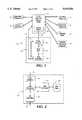
- FIG. 1shows a block diagram representation of the physical domain of an Automated Telecommunication Peripheral System 10 and associated components, in accordance with the preferred embodiment of the present invention.
- the system 10includes a peripheral node 30 which includes a node interface 32, a node audio response unit (ARU) 34, and a node controller 36.
- the node interface 32is connected through a network trunk group 22 to a carrier switch 20 of a public switched network (PSN) 12.
- PSNpublic switched network
- the node ARU 34is connected to the node interface 32 through an ARU trunk group 33 and to the node controller 36 through an ARU control line 35.
- the node controller 36is connected to the node interface 32 through an interface control line 37 and to the PSN 12 through a controller access line 38.
- An origination telephone 14, an access telephone 15, a destination telephone 16, a third party telephone 13, an operator bank 17, and a remote information provider 18are also shown connected to the PSN 12. Although represented as a single box, the origination telephone 14 represents a plurality of customer telephones serving one or more customers at one or more locations. Likewise, the access telephone 15, third party telephone 13, and destination telephone 16 represent pluralities of telephones. Furthermore, the remote information provider 18 represents a plurality remote systems providing a variety of services. Operation of the elements 14-18 will be discussed in greater detail below.
- the PSN 12includes a great variety of interconnecting switches, including local exchange carrier central offices (LEC CO's), access tandems, and long distance carrier points of presence (LDC POP's).
- LEC CO'slocal exchange carrier central offices
- LEC POP'slong distance carrier points of presence
- Examples of acceptable connection links between the origination telephone 14 and the peripheral node 30include equal access lines traveling through LEC CO's, direct access lines, and 800-number lines accessed through automatic dialers.
- the trunk groups 22, 33each represent a plurality of incoming and outgoing trunks having pluralities of communication paths.
- One example of an acceptable trunkis the common T1 line.
- the ARU control line 35 and the interface control line 37are data lines.
- One example of an acceptable data line for the ARU control line 35 and the interface control line 37is the common RS-232 line.
- the controller access line 38represents at least one ordinary telecommunication line which provides the node controller 36 access to the PSN 12 without going through the node interface 32.
- node interface 32 and node ARU 34are shown included in the peripheral node 30, it is understood that additional components are added to increase capacity of the peripheral node 30.
- the node ARU 34includes an ARU interface 45, an ARU processor 46, a disk controller 47, an ARU disk 48, and an I/O controller 49, connected as shown.
- the ARU 34is an audio peripheral which, under the direction of the node controller 36, records, plays, and analyzes audio signals, as is explained in greater detail below.
- the ARU processor 46controls the ARU interface 45, disk controller 47, and ARU disk 48 in response to commands received through the I/O controller 49 and ARU control line 35 from the node controller 36.
- the ARU interface 45is capable of detecting and producing dual tone multi-frequency (DTMF) signals and converting audio signals between T1 and ARU disk 48 formats.
- DTMFdual tone multi-frequency
- One example of an acceptable node ARU 34is the BTIII from Perception Technology Corp. of Canton, Mass.
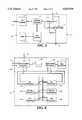
- FIG. 3shows a block diagram representation of the node interface 32 of FIG. 1.
- the node interface 32is shown including input ports 50, output ports 51, an interface processor 52, an I/O controller 53, a disk controller 54, and a disk 55, connected as shown.
- the PSN 12is configured to direct calls from the origination telephone 14, through the PSN 12 and network trunk group 22, and to specific input ports 50 on the node interface 32.
- Operation of the node interface 32is controlled by both the interface processor 52 and the node controller 36, which sends commands through the interface control line 37 and the I/O controller 53.
- One example of an acceptable node interface 32is the SDS-1000 from Summa Four of Manchester, N.H.
- Node controller 36is a fault tolerant, general purpose controller which offers utility grade service from a redundant architecture which is capable of processing many applications simultaneously.
- Two buses, A & Bare both connected to redundant hardware components, including I/O processors 62a & 62b, memory subsystems 63a & 63b, and CPU subsystems 64a & 64b.
- I/O processors 62a & 62bare both connected to communications subsystem 61 and disk subsystem 66 through disk control subsystem 65.
- the ARU control line 35, interface control line 37, and control access line 38are shown connected to communications subsystem 61.
- Terminal 60is also shown connected to communications subsystem 61.
- the redundant architecture of the node controller 36ensures continuous application reliability and availability. If one component fails, its partner component typically continues so that there are normally two components performing the same function at the same time. Also, each CPU subsystem 64a, 64b contains duplicate CPU's which process the same data at the same time, thus a total of four processors typically work on the same data at the same time. Logic comparators continually compare the results of each processor. If the processors on a board disagree, that particular board is taken off line, an error signal is generated, and its partner component continues without any processing degradation.
- CPU subsystems 64provide processor functions; memory subsystems 63 provide operating memory; and I/O processors 62 provide input and output capabilities.
- Disk control subsystem 65provides control of disk subsystem 64, which stores conventional operating system programming and application programming.
- Terminal 60provides human access to node controller 36 through communications subsystem 61.
- An acceptable node controller 36is the Stratus XA2000 model 30 from Stratus Computer, Inc. of Marlboro, Mass.
- FIG. 5is a block diagram representation of the program domain of the automated telecommunication peripheral system 10 of the preferred embodiment of the present invention.
- the programming domainrepresents programming found, in large part, on the node controller 36.
- Running below virtual operating system 70are background applications 72, interface server 74 and ARU server 72.
- the interface server 74accesses an input port table 78 and a dialed number table 80.
- Both the interface server 74 and the ARU server 76are connected to a monitor application 82, college registration application 88, generic application 89, and a bridge application 90.
- the connecting lines extending between the servers 74, 76 and applications 82, 88, 89, 90represent interprocess communication paths.
- the applications 82, 88, 89, 90represent pluralities of customized applications running simultaneously on the node controller 36.
- the monitor application 82is shown having access to a password file 84, a recorded file 85, and an on-line file 86.
- the bridge application 90is also shown having access to the recorded file 85 and the on-line file 86.
- the bridge application 90has access to an identification (ID) table 91, an automatic number identification (ANI) table 92, a personal identification number (PIN) table 93, a local credit file 99, a remote credit file 100 located on a remote information provider 18, and a destination validator 95, which is shown having access to a blocked file 97 and a remote file 98, located on the remote information provider 18 (FIG. 1).
- IDidentification
- ANIautomatic number identification
- PINpersonal identification number
- Background applications 72include applications which provide services which include, without limitation: billing, testing, error detection, and error notification.
- Billing servicesaccumulate and format transaction records of each caller into appropriate billing formats for use locally or by remote billing agencies, accessed through the controller access line 38 (FIG. 1).
- Testing servicesroutinely test various components throughout the system, including each communication path connected to the peripheral node 30.
- the error detection and error notification servicesevaluate error signals received from various components and the testing services to identify the various types of errors. Based on that information, appropriate service personnel are notified of the error. Notification steps may include directing the node ARU 34 and node interface 32 to call and announce to selected service personnel appropriate error messages or accessing radio paging systems to notify the service personnel.
- the interface server 74 and ARU server 76are multi-tasking, multi-threading processes which provide programming interfaces between applications and the node interface 32 and node ARU 34, respectively.
- the node controller 36utilizes servers and applications which reference files and tables during processing. Such a table-referencing method enhances customization, facilitates programming changes, and increases system availability.
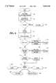
- FIGS. 6-12are flow chart representations of steps taken by the preferred embodiment of the present invention when executing a call-bridging process. Refer to previous Figures when references are made to components previously discussed.
- the collect-call bridging processis shown beginning in step 100 when a caller uses a selected customer telephone 14 to dial 0+ (destination number).
- the directory number assigned to the destination telephone 16 (and dialed by the caller)is referred to herein as the destination number
- the directory number assigned to the calling telephoneis referred to herein as the origination number.
- the PSN 12routes the call to the carrier switch 20.
- the carrier switch 20requests access to the peripheral node 30 (step 102) by signalling over the network trunk group 22 in a pre-defined format which is specific to a particular communication path leading into a particular input port 50.
- Several acceptable protocolsinclude Feature Group D, direct access lines (or equivalent), and 800-number access through a dialer.
- the Feature Group D and dialer methodsinclude supplying both the origination number and destination number, whereas the direct access method only supplies the destination number since the input port designation functions as an equivalent to the origination number for any direct access lines.
- a carriermay also provide Dialed Number Identification Service (DNIS), which provides digits corresponding, and functioning as an equivalent, to a particular destination number dialed by the caller.
- DNISDialed Number Identification Service
- the node interface 32After the node interface 32 receives the request for access from the carrier switch 20, the node interface 32 analyzes the data of the request to determine if access should be granted (decision 104). In the preferred embodiment of the present invention, the interface processor 52 of the node interface 32 compares the data to configuration tables saved on the disk 55 to determine if access is granted. If access is not granted, the process is terminated (step 106), as is discussed in greater detail below. If access is granted, the call is answered and data is transferred from the node interface 32 to the node controller 36 along the interface control line 37 (step 108). The transferred data corresponds to the origination number, the destination number (or equivalent), and input port identification data generated by the node interface 32.
- the program domain shown in FIG. 5is accessed.
- the interface server 74receives the transferred data and compares the interface identification data to the input port table 78 to select and initiate a customized application (step 110). If an input port 50 has been assigned to a particular application, such as a bridge application 90, the transferred data is then passed to the customized application through interprocess communication. However, if an input port 50 receives calls for many different applications, such as the monitor application 82, college registration application 88, or generic application 89, the interface server 74 also references the dialed number table 80 to select a particular application and pass thereto the transferred data. A collect-call bridge application 90 is selected and initiated at step 110.
- the first steps of the bridge application 90are to analyze the origination number and destination number to further configure the bridge application 90 since, in addition to utilizing a plurality of customized bridge applications 90 in the preferred embodiment of the present invention, one particular bridge application 90 is often used to service a variety of different customers, thus further configuring (or customizing) is necessary.
- the origination numberalso referred to as the ANI
- the ANI table 92to verify that the PSN 12 and carrier switch 20 only direct calls from selected customer origination telephones 14. If the origination number is invalid, the peripheral node 30 plays an announcement to the caller which indicates that the caller's telephone cannot access the peripheral node 30.
- the node controller 36under direction of the bridge application 90, interface server 74, and ARU server 76, directs the node ARU 34 to play a particular digitized message on one of the communication paths on the ARU trunk group 33 and directs the node interface 32 to bridge that communication path with the communication path leading through the network trunk group 22 to the origination telephone 14 so that the caller hears the announcement.
- the processis then terminated at step 116.
- the destination numberis checked (step 118) through the destination validator 95, which selectively accesses the blocked file 97 stored locally on the disk subsystem 66 (FIG. 4) and the remote file 98 stored remotely on the remote information provider 18 (FIG. 1).
- the destination numberis checked to verify that the owner of the destination number has not precluded calls from particular origination telephones 14 (blocked file 97) or requests for acceptance of collect-call charges (remote file 98). If the destination number is not valid, an announcement is played to the caller indicating why the call cannot be completed, and the process is terminated (steps 120, 122).
- the bridge application 90refers to the ID table 91 to determine, also based on the origination number, if special processing is required for this particular call, based on specific installation options (steps 124, 126).
- One optional special processincludes prompting a caller to transmit DTMF digits representing a personal identification number (PIN) and checking the caller's response against the PIN table 93. Such a process can be used to further limit access to the peripheral node 30.
- Another optional special processing routineincludes giving a caller an opportunity to choose, or example, Spanish prompts.
- Yet another routineincludes recording, or allowing real-time monitoring, of a caller's conversation, as is discussed in greater detail below.
- special processingalso refers to setting variables for optional processes which are delayed until later stages of the bridge application 90.
- Step 127refers to prompting the caller to choose, with a DTMF response, a billing method for the call. More specifically, the node controller 36 instructs the node interface 32 to connect an ARU trunk group 33 communication path to the caller's communication path on the network trunk group 22 and instructs the node ARU 34 to play a prompt requesting the caller to press a key corresponding to one of a several optional billing methods. The node ARU 34 is further instructed to analyze the response and relay the signal back to the node controller 36. If no response is received, the caller is prompted again and subsequently dropped by the peripheral node if the caller remains silent.
- the collect subroutine 300is executed.
- the calleris prompted for identification information (the caller's name), which is digitized and stored on the node ARU 34 (step 302).
- the calleris then placed on hold, and music is supplied to the caller's communication path by the node interface 32.
- the person-to-person billing methodis selected by the caller, the person-to-person subroutine 500 is executed.
- the person-to-person subroutine 500is very similar to the collect subroutine 300 in that the caller is prompted for identification and placed on hold. However, with the person-to-person subroutine, the caller is also prompted for identification of the destination party. With both options, the process continues in FIG. 10 at step 132.
- Step 402indicates that the caller is prompted for a DTMF representation of the third party number to which the call is to be billed, and the third party number is dialed.
- the node controller 36instructs the node ARU 34 to, after prompting the caller for, and subsequently recording, the third party number, transmit the third party number through an output port of the node interface 32 and the network trunk group 22 to the carrier switch 20.
- the peripheral node 30does not transmit destination-specific routing instructions to the carrier switch 20 since the peripheral node 30 is part of a peripheral system and, therefore, does not utilize destination-specific routing tables or files.
- the carrier switch 20, rather than the peripheral node 30,then attempts to route the call to the third party telephone 13.
- the peripheral node 30does not route any outgoing calls based on the outgoing number.
- the callis terminated if the third party does not answer the third party telephone 13 or if the third party telephone 13 is busy.
- the processreturns, upon this and other terminations throughout the process, to step 127 to give the caller an opportunity to choose another billing option.
- the elicit response subroutine 148is executed, as shown in FIG. 11.
- An announcementis first played notifying the third party that the caller is attempting to bill the third party for a call and requesting the third party to indicate, through transmitting a DTMF digit, whether or not the third party will accept the charges (step 166).
- Such an announcementincludes playing the digitized caller's name. If the third party responds to the announcement, the process continues in FIG. 8 (steps 168, 170).
- the peripheral node 30initiates another call to the operator bank 17 and bridges a live operator onto the third party's communication path through the node interface 32 (step 172).
- the operatormanually elicits a response (step 174) from the third party. If the third party needs the caller's name repeated, (step 176, 178) the operator can signal the peripheral node 30 to play the digitized caller's name again. After receiving the third party's response regarding acceptance of the charges, the operator signals an indication (step 180) back to the peripheral node 30. The process then continues in FIG. 8.
- step 406the process returns to step 127 to give the caller another billing option.
- step 132the process continue at step 132 in FIG. 10.
- Step 602represents prompting the caller for a credit account number and validating the credit number.
- Such validationincludes, optionally, performing local analysis, referring to a local credit file 99, or accessing a remote credit file 100. (FIG. 5). If the credit number cannot be validated, the call is terminated (step 606), or in alternate embodiments, given additional billing options (step 127). If the credit number is validated, the process continues at step 132 in FIG. 10.
- Step 134indicates that the peripheral node 30 calls the destination number to access the destination telephone 16. If there is no answer from the destination telephone 16, or if the destination telephone 16 is busy, (step 136) the bridge application 90 plays an appropriate "no answer" or "busy” message, respectively (steps 138, 140). The caller is then given the option of leaving a message for the destination party (steps 142-146). Voice messaging 146 includes recording a message from the caller and attempting to deliver the message to the destination party at at least one later point in time.
- the bridge application 90elicits a response (step 148) from the destination party if the caller selected a collect or person-to-person billing method.
- the elicit response subroutine 148is shown in FIG. 11. If the caller selected a collect call billing option, the elicit response subroutine 148 includes asking the destination party to accept the charges. If the caller selected a person-to-person billing option, the elicit response subroutine 148 includes verifying that the destination party is accurately identified by the stored destination party identification given by the caller. If the destination party does not accept the collect charges, or is not the party to whom the person-to-person call was directed, the call is terminated (steps 150, 152).
- the bridge application 90plays a branding message thanking the parties for using the peripheral node 30 (step 154).
- the callis then bridged through the node interface 32 (step 156).
- origination-specific special processing variables for monitoring the conversationare checked (step 158). Such steps include accessing the on-line file 86 to determine if any customer administrators (customers having monitoring access) are holding to monitor the conversation, as is discussed in more detail below.
- the bridge application 90continually monitors the conversation to detect a disconnect in order to terminate the bridge (steps 160, 164). Also, additional origination-specific special processing is optionally performed (step 162). Such special processing includes limiting durations of calls or playing overlaying messages to the parties advising them of various types of information, such as the length of the call.
- the process of terminating a callinvolves several steps. First, all communication paths are closed which may still be open on any inbound or outbound ports on the node interface 32 connected to either the network trunk group 22 or the ARU trunk group 33 which have been associated with this particular call. Then, a call detail record including the length of the call is created by the background application 72 and processed. Transmission of the billing records through the controller access line 38 to a billing service optionally occurs immediately after each call or on a batch basis. Finally, optional special processing occurs, such as saving a recorded conversation and updating the recorded file 85.
- FIG. 12shows a flow chart representation of the process of accessing the peripheral node 30 to monitor caller conversations, including monitoring previously-recorded conversations and on-line, real-time conversations.
- the carrier switch 20requests access to the peripheral node 30 (step 202). If access is granted by the node interface 32, (step 204) the origination number, dialed number (destination number), and input port identification data are transmitted to the node controller 36 (step 208).
- the interface server 74then references the input port table 78 and dialed number table 80 to select and initiate a particular monitor application 82 (step 210).
- the monitor application 82then directs the ARU server 76 and interface server 74 to direct the node ARU 34 and node interface 32, respectively, to prompt the customer administrator for a password, record the customer administrator's response, and transmit the response back to the node controller 36 for analysis.
- the node controller 36analyzes the password response and compares it to the password file 84 (step 212). If the password is not valid, the process is terminated (steps 214, 216). If the password is valid, the customer administrator is prompted to select on-line or recorded monitoring. (step 218)
- the customer administratorselects on-line monitoring, the customer administrator is prompted for selection criteria to determine which types of conversations are to be monitored (step 226).
- a customer administratormay choose to monitor all calls from one or more origination telephones 14, to one or more destination telephones 16, by one or more callers with identified by distinct PIN's, or any combination thereof.
- a flagis set in the on-line file 86 which acts as a signal to all currently proceeding and future bridge applications 90 that a customer administrator desires to monitor certain types of conversations (step 228). If a match is ever found, the appropriate bridge application 90 will create a bridge to allow the customer administrator to listen to the conversation.
- the customer administratorselects recorded monitoring, the customer administrator is again prompted for selection criteria (step 220).
- the monitor application 82accesses the recorded file 85 to determine if any recorded conversations match the selection criteria. If matches are found, the monitor application directs the node ARU 34 to play the conversations to the customer administrator (step 222). After monitoring is completed, the application is terminated (step 224).
- 900-type numbersare similar to ordinary telephone calls with the exception that they normally cost callers additional money which is paid to the service provider
- Student callerswould enter registration information in response to audio prompts, and the node controller 36 would interface with another remote information provider 18, which would be a particular college registration computer in this application. Alternately, the registration could be handled completely by the node controller 36 without real-time interfacing with any another computer.
- the generic application 89represents a plurality of other telecommunication peripheral services including banking and credit card information services, check guarantee services, catalog ordering services, stock market information services, and various types of news services. The actual steps taken by these applications depend on the type of information being exchanged.
- voice recognition componentsare included in the node ARU 34 to discriminate audio responses in addition to the standard DTMF responses.
- the voice recognition componentallows applications to accept DTMF or voice responses from callers.
- One example of an acceptable voice recognition componentis available from Perception Technology Corp. of Canton, Mass.
- a plurality of peripheral nodes 30are distributed over a wide area, and the public switched network is configured to direct calls to an alternate peripheral node 30 upon unavailability of a primary peripheral node 30.
- a central controllersimilar to the node controller 36, is connected through a wide-area network to the plurality of peripheral nodes 30 and provides diagnostic and node configuration alteration functions.
- one central controlleris used to replace all of the node controllers 36 so that the central controller actively controls each and every peripheral node over the wide area network.
Landscapes
- Engineering & Computer Science (AREA)
- Signal Processing (AREA)
- Computer Networks & Wireless Communication (AREA)
- Computer Security & Cryptography (AREA)
- Technology Law (AREA)
- Marketing (AREA)
- Business, Economics & Management (AREA)
- Telephonic Communication Services (AREA)
- Electrotherapy Devices (AREA)
- Control Of Motors That Do Not Use Commutators (AREA)
- Air Conditioning Control Device (AREA)
- Financial Or Insurance-Related Operations Such As Payment And Settlement (AREA)
- Sorption Type Refrigeration Machines (AREA)
- Exchange Systems With Centralized Control (AREA)
- Selective Calling Equipment (AREA)
Abstract
Description
Claims (14)
Priority Applications (1)
| Application Number | Priority Date | Filing Date | Title |
|---|---|---|---|
| US08/259,853US5619556A (en) | 1990-10-01 | 1994-06-15 | Automated telecommunication peripheral system |
Applications Claiming Priority (4)
| Application Number | Priority Date | Filing Date | Title |
|---|---|---|---|
| US07/591,047US5113430A (en) | 1990-10-01 | 1990-10-01 | Enhanced wide area audio response network |
| US07/852,491US5317627A (en) | 1990-10-01 | 1992-03-16 | Enhanced wide area audio response network |
| US07/861,625US5335266A (en) | 1990-10-01 | 1992-04-01 | Automated telecommunication peripheral system |
| US08/259,853US5619556A (en) | 1990-10-01 | 1994-06-15 | Automated telecommunication peripheral system |
Related Parent Applications (1)
| Application Number | Title | Priority Date | Filing Date |
|---|---|---|---|
| US07/861,625ContinuationUS5335266A (en) | 1990-10-01 | 1992-04-01 | Automated telecommunication peripheral system |
Publications (1)
| Publication Number | Publication Date |
|---|---|
| US5619556Atrue US5619556A (en) | 1997-04-08 |
Family
ID=25336313
Family Applications (2)
| Application Number | Title | Priority Date | Filing Date |
|---|---|---|---|
| US07/861,625Expired - LifetimeUS5335266A (en) | 1990-10-01 | 1992-04-01 | Automated telecommunication peripheral system |
| US08/259,853Expired - LifetimeUS5619556A (en) | 1990-10-01 | 1994-06-15 | Automated telecommunication peripheral system |
Family Applications Before (1)
| Application Number | Title | Priority Date | Filing Date |
|---|---|---|---|
| US07/861,625Expired - LifetimeUS5335266A (en) | 1990-10-01 | 1992-04-01 | Automated telecommunication peripheral system |
Country Status (7)
| Country | Link |
|---|---|
| US (2) | US5335266A (en) |
| EP (1) | EP0634070B1 (en) |
| AT (1) | ATE210351T1 (en) |
| AU (1) | AU686997B2 (en) |
| CA (1) | CA2133426C (en) |
| DE (1) | DE69331264T2 (en) |
| WO (1) | WO1993020639A1 (en) |
Cited By (17)
| Publication number | Priority date | Publication date | Assignee | Title |
|---|---|---|---|---|
| US5835572A (en)* | 1990-10-01 | 1998-11-10 | United States Advanced Network, Inc. | Customized, billing controlled call bridging system |
| US5963625A (en)* | 1996-09-30 | 1999-10-05 | At&T Corp | Method for providing called service provider control of caller access to pay services |
| US6091714A (en)* | 1997-04-30 | 2000-07-18 | Sensel; Steven D. | Programmable distributed digital switch system |
| US6198947B1 (en)* | 1996-02-28 | 2001-03-06 | Oki Telecom, Inc. | External control unit with reduced keypad integrated in voice activated vehicular telephone system with call-in-process voice-to-tones and voice to-memory conversion facilities |
| WO2001067760A1 (en)* | 2000-03-09 | 2001-09-13 | Planetary Television.Com, Llc | Method and apparatus for providing interactive video communications services |
| WO2000054478A3 (en)* | 1999-03-11 | 2002-02-28 | Siemens Ag | Method for providing information concerning charges for subscribers of a telecommunications network by using electronic mail |
| WO2002065748A1 (en)* | 2001-02-15 | 2002-08-22 | Deutsche Telekom Ag | Automated call-back call |
| EP1345466A1 (en)* | 2002-03-12 | 2003-09-17 | Siemens AG | Method and device for providing a value-added service in a communications network |
| US6792082B1 (en)* | 1998-09-11 | 2004-09-14 | Comverse Ltd. | Voice mail system with personal assistant provisioning |
| US20050201539A1 (en)* | 2004-03-15 | 2005-09-15 | Sbc Knowledge Ventures, L.P. | Credit card collect call system and method |
| EP1104158A4 (en)* | 1998-08-05 | 2005-10-26 | Takanobu Kunugi | Communication control system and communication control method |
| US20050286706A1 (en)* | 2004-06-22 | 2005-12-29 | David Fuller | Recorded call playback |
| US7085362B1 (en)* | 1995-09-08 | 2006-08-01 | Sprint Communications Company L.P. | System for managing telecommunications |
| US20090161855A1 (en)* | 2007-12-20 | 2009-06-25 | Embarq Holdings Company Llc | System and method for hold and re-ring |
| US20090268895A1 (en)* | 2008-04-23 | 2009-10-29 | Embarq Holdings Company, Llc | System and Method for Network Based Call Transfers |
| US20100009665A1 (en)* | 2008-07-14 | 2010-01-14 | Embarq Holdings Company, Llc | System and method for providing emergency call forwarding services |
| US9036803B2 (en) | 2008-06-25 | 2015-05-19 | Centurylink Intellectual Property Llc | System and method for providing advanced call forwarding functionality |
Families Citing this family (42)
| Publication number | Priority date | Publication date | Assignee | Title |
|---|---|---|---|---|
| US6192254B1 (en)* | 1992-02-28 | 2001-02-20 | At&T Corporation | Personal portable apparatus for use in completing a telephone call |
| CA2091658A1 (en)* | 1993-03-15 | 1994-09-16 | Matthew Lennig | Method and apparatus for automation of directory assistance using speech recognition |
| US5463677A (en)* | 1993-05-27 | 1995-10-31 | At&T Corp. | Method and apparatus for facilitating the making of collect calls |
| US5485507A (en)* | 1993-08-20 | 1996-01-16 | Gateway Technologies, Inc. | Integrated commissary system |
| US5535261A (en)* | 1993-08-20 | 1996-07-09 | Gateway Technologies, Inc. | Selectively activated integrated real-time recording of telephone conversations |
| US5590186A (en)* | 1993-12-22 | 1996-12-31 | At & T | System and method for redirecting a telephone call with call merging |
| US5841854A (en)* | 1994-02-16 | 1998-11-24 | Priority Call Management, Inc. | Wireless telephone integration system and method for call centers and workgroups |
| US5862208A (en)* | 1994-02-16 | 1999-01-19 | Priority Call Management, Inc. | Method and system for enabling a party to change terminals during a call |
| US5703935A (en)* | 1994-03-29 | 1997-12-30 | Mci Communications Corporation | Automated telephone operator services |
| US5666400A (en)* | 1994-07-07 | 1997-09-09 | Bell Atlantic Network Services, Inc. | Intelligent recognition |
| KR0138181B1 (en)* | 1995-06-13 | 1998-07-01 | 김광호 | Line test device |
| US5666405A (en)* | 1995-07-14 | 1997-09-09 | At&T | True family telecommunication service |
| KR970019302A (en)* | 1995-09-29 | 1997-04-30 | 김광호 | Apparatus and method for interfacing between a standalone voice mail device and a switching system |
| US5764732A (en)* | 1995-12-29 | 1998-06-09 | At&T Corp | Called party mailbox service |
| US5802156A (en)* | 1996-06-05 | 1998-09-01 | David Felger | Method for billing and controlling fraud in providing pay information services |
| US7555458B1 (en) | 1996-06-05 | 2009-06-30 | Fraud Control System.Com Corporation | Method of billing a purchase made over a computer network |
| US20030195846A1 (en) | 1996-06-05 | 2003-10-16 | David Felger | Method of billing a purchase made over a computer network |
| US6282276B1 (en) | 1996-06-05 | 2001-08-28 | David Felger | Method of billing a value-added call |
| US6553108B1 (en) | 1996-06-05 | 2003-04-22 | David Felger | Method of billing a communication session conducted over a computer network |
| US7013001B1 (en) | 1996-06-05 | 2006-03-14 | David Felger | Method of billing a communication session conducted over a computer network |
| US8229844B2 (en) | 1996-06-05 | 2012-07-24 | Fraud Control Systems.Com Corporation | Method of billing a purchase made over a computer network |
| US6038309A (en)* | 1996-06-13 | 2000-03-14 | Northern Telecom Limited | Apparatus and method for externally controlling processing of a service call |
| US6028924A (en)* | 1996-06-13 | 2000-02-22 | Northern Telecom Limited | Apparatus and method for controlling processing of a service call |
| US5991389A (en)* | 1996-06-13 | 1999-11-23 | Northern Telecom Limited | Programmable service architecture for call control processing |
| US5875401A (en)* | 1996-07-12 | 1999-02-23 | At & T Corp. | Method and apparatus for initiating wireless messages |
| CN1177458C (en)* | 1996-09-23 | 2004-11-24 | 西门子公司 | Device for the indirect transmission of information in a data network and/or a communication network |
| DE19800716A1 (en) | 1998-01-12 | 1999-07-15 | Deutsche Telekom Ag | Method for providing an extension function in telecommunications systems |
| US6665376B1 (en) | 1998-10-23 | 2003-12-16 | T-Netix, Inc. | Selectively activated integrated real-time recording of telephone conversations with automated documentation of consent to call recording |
| US6404746B1 (en)* | 1999-07-13 | 2002-06-11 | Intervoice Limited Partnership | System and method for packet network media redirection |
| US6683942B1 (en) | 1999-09-10 | 2004-01-27 | Comdial Corporation | Telephone switching system with data integration |
| US6473825B1 (en)* | 2000-01-12 | 2002-10-29 | Trw Inc. | Apparatus and method for controlling secure communications between peripheral components on computer buses connected by a bridge circuit |
| US7505406B1 (en) | 2001-07-13 | 2009-03-17 | Evercom Systems, Inc. | Public telephone control with voice over internet protocol transmission |
| US8000269B1 (en) | 2001-07-13 | 2011-08-16 | Securus Technologies, Inc. | Call processing with voice over internet protocol transmission |
| US7899167B1 (en) | 2003-08-15 | 2011-03-01 | Securus Technologies, Inc. | Centralized call processing |
| US9026468B2 (en) | 2002-04-29 | 2015-05-05 | Securus Technologies, Inc. | System and method for proactively establishing a third-party payment account for services rendered to a resident of a controlled-environment facility |
| US9020114B2 (en) | 2002-04-29 | 2015-04-28 | Securus Technologies, Inc. | Systems and methods for detecting a call anomaly using biometric identification |
| US7916845B2 (en) | 2006-04-13 | 2011-03-29 | Securus Technologies, Inc. | Unauthorized call activity detection and prevention systems and methods for a Voice over Internet Protocol environment |
| US7860222B1 (en) | 2003-11-24 | 2010-12-28 | Securus Technologies, Inc. | Systems and methods for acquiring, accessing, and analyzing investigative information |
| US7876744B2 (en)* | 2002-11-14 | 2011-01-25 | Ey-Taeg Kwon | Method for collect call service based on VoIP technology and system thereof |
| US7529357B1 (en) | 2003-08-15 | 2009-05-05 | Evercom Systems, Inc. | Inmate management and call processing systems and methods |
| US7809120B2 (en)* | 2005-06-29 | 2010-10-05 | Forrest Ii Alfred T | Collect credit card service |
| US10796392B1 (en) | 2007-05-22 | 2020-10-06 | Securus Technologies, Llc | Systems and methods for facilitating booking, bonding and release |
Citations (49)
| Publication number | Priority date | Publication date | Assignee | Title |
|---|---|---|---|---|
| US3728486A (en)* | 1971-08-26 | 1973-04-17 | C Kraus | Voicegram service |
| US4071698A (en)* | 1977-01-10 | 1978-01-31 | Franklin V. Barger, Jr. | Telephone system for audio demonstration and marketing of goods or services |
| US4188507A (en)* | 1977-08-10 | 1980-02-12 | Dictaphone Corporation | Remotely controlled telephone answering apparatus |
| US4229624A (en)* | 1978-12-21 | 1980-10-21 | Bell Telephone Laboratories, Incorporated | Switching network control arrangement |
| US4255619A (en)* | 1978-10-14 | 1981-03-10 | Keihin Electric Express Railway Co., Ltd. | Telephone reservation-processing system |
| US4317007A (en)* | 1979-03-23 | 1982-02-23 | Small World Exchange, Inc. | Telephone-conferencing method and apparatus with monitor-only access |
| US4320256A (en)* | 1979-11-27 | 1982-03-16 | Freeman Michael J | Verbally interactive telephone interrogation system with selectible variable decision tree |
| US4371752A (en)* | 1979-11-26 | 1983-02-01 | Ecs Telecommunications, Inc. | Electronic audio communication system |
| US4489438A (en)* | 1982-02-01 | 1984-12-18 | National Data Corporation | Audio response system |
| US4577062A (en)* | 1983-09-02 | 1986-03-18 | Butler National Corporation | Method for dispensing information |
| US4598367A (en)* | 1983-11-09 | 1986-07-01 | Financial Design Systems, Inc. | Financial quotation system using synthesized speech |
| US4611094A (en)* | 1983-12-01 | 1986-09-09 | At&T Bell Laboratories | Method for customer definable telephone capability |
| US4649563A (en)* | 1984-04-02 | 1987-03-10 | R L Associates | Method of and means for accessing computerized data bases utilizing a touch-tone telephone instrument |
| US4663777A (en)* | 1984-12-17 | 1987-05-05 | Charles Szeto | Apparatus for controlling digital voice recording and playback over telephone lines and adapted for use with standard host computers |
| US4716583A (en)* | 1983-11-16 | 1987-12-29 | Speech Plus, Inc. | Verbal computer terminal system |
| US4757267A (en)* | 1987-06-17 | 1988-07-12 | Applied Telematics, Inc. | Telephone system for connecting a customer to a supplier of goods |
| US4766604A (en)* | 1986-11-07 | 1988-08-23 | Messagephone, Inc. | Method for receiving and delivering voice messages |
| US4792968A (en)* | 1985-07-10 | 1988-12-20 | Fdr Interactive Technologies | Statistical analysis system for use with public communication facility |
| US4797910A (en)* | 1986-05-07 | 1989-01-10 | American Telphone And Telegraph Company, At&T Bell Laboratories | Automated operator assistance calls with voice processing |
| US4811382A (en)* | 1986-09-05 | 1989-03-07 | Sleevi Neil F | Method and apparatus for applying messages in a telecommunications network |
| US4817130A (en)* | 1986-09-11 | 1989-03-28 | International Telesystems Corporation | Call management system with protocol converter and port controller |
| US4827500A (en)* | 1987-01-30 | 1989-05-02 | American Telephone And Telegraph Company, At&T Bell Laboratories | Automatic speech recognition to select among call destinations |
| US4829514A (en)* | 1987-03-18 | 1989-05-09 | International Telesystems Corporation | Digital voice recording and reproduction and telephone network signalling using direct storage in RAM of PCM encoded data |
| US4845739A (en)* | 1985-07-10 | 1989-07-04 | Fdr Interactive Technologies | Telephonic-interface statistical analysis system |
| US4893335A (en)* | 1984-09-14 | 1990-01-09 | Fuller Research And Development Company | Remote access telephone control system |
| US4899375A (en)* | 1988-09-23 | 1990-02-06 | American Telephone & Telegraph Company, At&T Bell Laboratories | More efficient call handling for operator assistance calls |
| US4901341A (en)* | 1988-06-22 | 1990-02-13 | Messager Partners | Method and apparatus for caller-controlled receipt and delivery of voice messages |
| US4908850A (en)* | 1988-01-11 | 1990-03-13 | American Communications & Engineering, Inc. | Voice services network with automated billing |
| US4922520A (en)* | 1986-12-31 | 1990-05-01 | M. A. Kempner, Inc. | Automatic telephone polling system |
| US4922519A (en)* | 1986-05-07 | 1990-05-01 | American Telephone And Telegraph Company | Automated operator assistance calls with voice processing |
| US4930150A (en)* | 1985-07-10 | 1990-05-29 | First Data Resources Inc. | Telephonic interface control system |
| US4933966A (en)* | 1989-01-23 | 1990-06-12 | Intellicall, Inc. | Method and apparatus for performing an automated collect call |
| US4933967A (en)* | 1989-06-01 | 1990-06-12 | At&T Company | Automatically-effected move of a subscriber between electronic message service systems in a network |
| US4935956A (en)* | 1988-05-02 | 1990-06-19 | Telequip Ventures, Inc. | Automated public phone control for charge and collect billing |
| US4947422A (en)* | 1988-03-07 | 1990-08-07 | Digital Telecommunications Systems, Inc. | Personalized telephone for automatic access to operator services |
| US4954958A (en)* | 1988-08-19 | 1990-09-04 | Hacowie Corporation | Directional information system |
| US5003534A (en)* | 1988-08-26 | 1991-03-26 | Scientific Atlanta | Link utilization control mechanism for demand assignment satellite communications network |
| US5014303A (en)* | 1989-12-18 | 1991-05-07 | Bell Communications Research, Inc. | Operator services using speech processing |
| US5023868A (en)* | 1988-12-29 | 1991-06-11 | At&T Bell Laboratories | Automated call handling apparatus |
| US5048075A (en)* | 1985-07-10 | 1991-09-10 | First Data Resources Inc. | Telephonic-interface statistical analysis system |
| WO1991018466A1 (en)* | 1990-05-16 | 1991-11-28 | Messager Partners | Method and apparatus for providing proactive call services following call completion |
| US5163083A (en)* | 1990-10-12 | 1992-11-10 | At&T Bell Laboratories | Automation of telephone operator assistance calls |
| US5185781A (en)* | 1990-10-12 | 1993-02-09 | At&T Bell Laboratories | Automation of telephone operator assistance calls |
| US5199062A (en)* | 1988-01-20 | 1993-03-30 | Phone Base Systems Inc. | Telephone communications system including a digital telephone switch, a voice response unit and a stored program sequence for controlling both the switch and the voice response unit |
| US5255309A (en)* | 1985-07-10 | 1993-10-19 | First Data Resources Inc. | Telephonic-interface statistical analysis system |
| US5355403A (en)* | 1990-10-01 | 1994-10-11 | United States Advance Network, Inc. | Customized, billing-controlled call bridging system |
| US5375161A (en)* | 1984-09-14 | 1994-12-20 | Accessline Technologies, Inc. | Telephone control system with branch routing |
| US5392357A (en)* | 1991-12-09 | 1995-02-21 | At&T Corp. | Secure telecommunications |
| US5535261A (en)* | 1993-08-20 | 1996-07-09 | Gateway Technologies, Inc. | Selectively activated integrated real-time recording of telephone conversations |
Family Cites Families (2)
| Publication number | Priority date | Publication date | Assignee | Title |
|---|---|---|---|---|
| FR2653623B1 (en)* | 1989-10-20 | 1995-12-22 | Jean Pierre Dufour | PROCESS ALLOWING THE SUBSCRIBER APPLICANT TO TELEPHONE FOR FREE TO THE SUBSCRIBER OF HIS CHOICE BY MEANS OF LISTENING TO ADVERTISING. |
| WO1992022165A1 (en)* | 1991-06-04 | 1992-12-10 | Telsis Holdings Limited | Voice services equipment |
- 1992
- 1992-04-01USUS07/861,625patent/US5335266A/ennot_activeExpired - Lifetime
- 1993
- 1993-03-19EPEP93907608Apatent/EP0634070B1/ennot_activeExpired - Lifetime
- 1993-03-19CACA002133426Apatent/CA2133426C/ennot_activeExpired - Lifetime
- 1993-03-19DEDE69331264Tpatent/DE69331264T2/ennot_activeExpired - Lifetime
- 1993-03-19AUAU38147/93Apatent/AU686997B2/ennot_activeExpired
- 1993-03-19WOPCT/US1993/002561patent/WO1993020639A1/enactiveIP Right Grant
- 1993-03-19ATAT93907608Tpatent/ATE210351T1/ennot_activeIP Right Cessation
- 1994
- 1994-06-15USUS08/259,853patent/US5619556A/ennot_activeExpired - Lifetime
Patent Citations (51)
| Publication number | Priority date | Publication date | Assignee | Title |
|---|---|---|---|---|
| US3728486A (en)* | 1971-08-26 | 1973-04-17 | C Kraus | Voicegram service |
| US4071698A (en)* | 1977-01-10 | 1978-01-31 | Franklin V. Barger, Jr. | Telephone system for audio demonstration and marketing of goods or services |
| US4188507A (en)* | 1977-08-10 | 1980-02-12 | Dictaphone Corporation | Remotely controlled telephone answering apparatus |
| US4255619A (en)* | 1978-10-14 | 1981-03-10 | Keihin Electric Express Railway Co., Ltd. | Telephone reservation-processing system |
| US4229624A (en)* | 1978-12-21 | 1980-10-21 | Bell Telephone Laboratories, Incorporated | Switching network control arrangement |
| US4317007A (en)* | 1979-03-23 | 1982-02-23 | Small World Exchange, Inc. | Telephone-conferencing method and apparatus with monitor-only access |
| US4371752A (en)* | 1979-11-26 | 1983-02-01 | Ecs Telecommunications, Inc. | Electronic audio communication system |
| US4320256A (en)* | 1979-11-27 | 1982-03-16 | Freeman Michael J | Verbally interactive telephone interrogation system with selectible variable decision tree |
| US4489438A (en)* | 1982-02-01 | 1984-12-18 | National Data Corporation | Audio response system |
| US4577062A (en)* | 1983-09-02 | 1986-03-18 | Butler National Corporation | Method for dispensing information |
| US4598367A (en)* | 1983-11-09 | 1986-07-01 | Financial Design Systems, Inc. | Financial quotation system using synthesized speech |
| US4716583A (en)* | 1983-11-16 | 1987-12-29 | Speech Plus, Inc. | Verbal computer terminal system |
| US4611094A (en)* | 1983-12-01 | 1986-09-09 | At&T Bell Laboratories | Method for customer definable telephone capability |
| US4649563A (en)* | 1984-04-02 | 1987-03-10 | R L Associates | Method of and means for accessing computerized data bases utilizing a touch-tone telephone instrument |
| US5375161A (en)* | 1984-09-14 | 1994-12-20 | Accessline Technologies, Inc. | Telephone control system with branch routing |
| US4893335A (en)* | 1984-09-14 | 1990-01-09 | Fuller Research And Development Company | Remote access telephone control system |
| US4663777A (en)* | 1984-12-17 | 1987-05-05 | Charles Szeto | Apparatus for controlling digital voice recording and playback over telephone lines and adapted for use with standard host computers |
| US4845739A (en)* | 1985-07-10 | 1989-07-04 | Fdr Interactive Technologies | Telephonic-interface statistical analysis system |
| US4792968A (en)* | 1985-07-10 | 1988-12-20 | Fdr Interactive Technologies | Statistical analysis system for use with public communication facility |
| US5048075A (en)* | 1985-07-10 | 1991-09-10 | First Data Resources Inc. | Telephonic-interface statistical analysis system |
| US5255309A (en)* | 1985-07-10 | 1993-10-19 | First Data Resources Inc. | Telephonic-interface statistical analysis system |
| US4930150A (en)* | 1985-07-10 | 1990-05-29 | First Data Resources Inc. | Telephonic interface control system |
| US4797910A (en)* | 1986-05-07 | 1989-01-10 | American Telphone And Telegraph Company, At&T Bell Laboratories | Automated operator assistance calls with voice processing |
| US4922519A (en)* | 1986-05-07 | 1990-05-01 | American Telephone And Telegraph Company | Automated operator assistance calls with voice processing |
| US4811382A (en)* | 1986-09-05 | 1989-03-07 | Sleevi Neil F | Method and apparatus for applying messages in a telecommunications network |
| US4817130A (en)* | 1986-09-11 | 1989-03-28 | International Telesystems Corporation | Call management system with protocol converter and port controller |
| US4766604A (en)* | 1986-11-07 | 1988-08-23 | Messagephone, Inc. | Method for receiving and delivering voice messages |
| US4922520A (en)* | 1986-12-31 | 1990-05-01 | M. A. Kempner, Inc. | Automatic telephone polling system |
| US4827500A (en)* | 1987-01-30 | 1989-05-02 | American Telephone And Telegraph Company, At&T Bell Laboratories | Automatic speech recognition to select among call destinations |
| US4829514A (en)* | 1987-03-18 | 1989-05-09 | International Telesystems Corporation | Digital voice recording and reproduction and telephone network signalling using direct storage in RAM of PCM encoded data |
| US4757267B1 (en)* | 1987-06-17 | 1991-05-21 | Applied Telematics Inc | |
| US4757267A (en)* | 1987-06-17 | 1988-07-12 | Applied Telematics, Inc. | Telephone system for connecting a customer to a supplier of goods |
| US4908850A (en)* | 1988-01-11 | 1990-03-13 | American Communications & Engineering, Inc. | Voice services network with automated billing |
| US4908850B1 (en)* | 1988-01-11 | 1995-02-07 | American Communications & Engi | Voice services network with automated billing |
| US5199062A (en)* | 1988-01-20 | 1993-03-30 | Phone Base Systems Inc. | Telephone communications system including a digital telephone switch, a voice response unit and a stored program sequence for controlling both the switch and the voice response unit |
| US4947422A (en)* | 1988-03-07 | 1990-08-07 | Digital Telecommunications Systems, Inc. | Personalized telephone for automatic access to operator services |
| US4935956A (en)* | 1988-05-02 | 1990-06-19 | Telequip Ventures, Inc. | Automated public phone control for charge and collect billing |
| US4901341A (en)* | 1988-06-22 | 1990-02-13 | Messager Partners | Method and apparatus for caller-controlled receipt and delivery of voice messages |
| US4954958A (en)* | 1988-08-19 | 1990-09-04 | Hacowie Corporation | Directional information system |
| US5003534A (en)* | 1988-08-26 | 1991-03-26 | Scientific Atlanta | Link utilization control mechanism for demand assignment satellite communications network |
| US4899375A (en)* | 1988-09-23 | 1990-02-06 | American Telephone & Telegraph Company, At&T Bell Laboratories | More efficient call handling for operator assistance calls |
| US5023868A (en)* | 1988-12-29 | 1991-06-11 | At&T Bell Laboratories | Automated call handling apparatus |
| US4933966A (en)* | 1989-01-23 | 1990-06-12 | Intellicall, Inc. | Method and apparatus for performing an automated collect call |
| US4933967A (en)* | 1989-06-01 | 1990-06-12 | At&T Company | Automatically-effected move of a subscriber between electronic message service systems in a network |
| US5014303A (en)* | 1989-12-18 | 1991-05-07 | Bell Communications Research, Inc. | Operator services using speech processing |
| WO1991018466A1 (en)* | 1990-05-16 | 1991-11-28 | Messager Partners | Method and apparatus for providing proactive call services following call completion |
| US5355403A (en)* | 1990-10-01 | 1994-10-11 | United States Advance Network, Inc. | Customized, billing-controlled call bridging system |
| US5185781A (en)* | 1990-10-12 | 1993-02-09 | At&T Bell Laboratories | Automation of telephone operator assistance calls |
| US5163083A (en)* | 1990-10-12 | 1992-11-10 | At&T Bell Laboratories | Automation of telephone operator assistance calls |
| US5392357A (en)* | 1991-12-09 | 1995-02-21 | At&T Corp. | Secure telecommunications |
| US5535261A (en)* | 1993-08-20 | 1996-07-09 | Gateway Technologies, Inc. | Selectively activated integrated real-time recording of telephone conversations |
Non-Patent Citations (16)
| Title |
|---|
| 2nd IEEE National Conference on Telecommunications P. P. Cretch, A. R. Allwood E.S.P. Allard, A Network For Recorded Information Distribution; Apr. 1989, pp. 10 14.* |
| 2nd IEEE National Conference on Telecommunications--P. P. Cretch, A. R. Allwood E.S.P. Allard, A Network For Recorded Information Distribution; Apr. 1989, pp. 10-14. |
| AT&T s Conversant I Voice System John P. Moosemiller, Mar./Apr. 1986 Speech Technology pp. 88 93.* |
| AT&T's Conversant I Voice System--John P. Moosemiller, Mar./Apr. 1986 Speech Technology--pp. 88-93. |
| Conversant Voice System: Architecture and Applications; Robert J. Perdue, Eugene L. Rissanen; AT&T Technical Journal, pp. 34 47.* |
| Conversant Voice System: Architecture and Applications; Robert J. Perdue, Eugene L. Rissanen; AT&T Technical Journal, pp. 34-47. |
| Customer Control of Network Services, G. A. Raack, E. G. Sable, R. J. Stewart, Oct. 1984 vol. 22. No. 10 IEEE Com. Mag. pp. 8 14.* |
| Customer Control of Network Services, G. A. Raack, E. G. Sable, R. J. Stewart, Oct. 1984--vol. 22. No. 10--IEEE Com. Mag. pp. 8-14. |
| David R. Fischell, Sarbmeet S. Kanwal, Daniel Furman Interactive Voice Technology Applications AT&T Technical Journal, Sep./Oct. 1990, pp. 61 76.* |
| David R. Fischell, Sarbmeet S. Kanwal, Daniel Furman--Interactive Voice Technology Applications--AT&T Technical Journal, Sep./Oct. 1990, pp. 61-76. |
| David S. Cheeseman, Martin B. Cooper Radion and Electronic Engineer vol. 53 (1983) Voice Signaling In The Telephone Network pp. 241 247.* |
| David S. Cheeseman, Martin B. Cooper--Radion and Electronic Engineer vol. 53 (1983) Voice Signaling In The Telephone Network--pp. 241-247. |
| Tele Matic Brochure Conquest III Inmate Telephone System Publ. date unknown.* |
| Tele-Matic Brochure--Conquest III Inmate Telephone System--Publ. date unknown. |
| Vac Brochure System 20 Valve Added Communications Publ. date unknown.* |
| Vac Brochure--System 20 Valve Added Communications Publ. date unknown. |
Cited By (26)
| Publication number | Priority date | Publication date | Assignee | Title |
|---|---|---|---|---|
| US5943403A (en)* | 1990-10-01 | 1999-08-24 | United States Advance Network, Inc. | Customized, billing-controlled call bridging system |
| US5835572A (en)* | 1990-10-01 | 1998-11-10 | United States Advanced Network, Inc. | Customized, billing controlled call bridging system |
| US7085362B1 (en)* | 1995-09-08 | 2006-08-01 | Sprint Communications Company L.P. | System for managing telecommunications |
| US6198947B1 (en)* | 1996-02-28 | 2001-03-06 | Oki Telecom, Inc. | External control unit with reduced keypad integrated in voice activated vehicular telephone system with call-in-process voice-to-tones and voice to-memory conversion facilities |
| US5963625A (en)* | 1996-09-30 | 1999-10-05 | At&T Corp | Method for providing called service provider control of caller access to pay services |
| US6091714A (en)* | 1997-04-30 | 2000-07-18 | Sensel; Steven D. | Programmable distributed digital switch system |
| EP1104158A4 (en)* | 1998-08-05 | 2005-10-26 | Takanobu Kunugi | Communication control system and communication control method |
| US6792082B1 (en)* | 1998-09-11 | 2004-09-14 | Comverse Ltd. | Voice mail system with personal assistant provisioning |
| WO2000054478A3 (en)* | 1999-03-11 | 2002-02-28 | Siemens Ag | Method for providing information concerning charges for subscribers of a telecommunications network by using electronic mail |
| WO2001067760A1 (en)* | 2000-03-09 | 2001-09-13 | Planetary Television.Com, Llc | Method and apparatus for providing interactive video communications services |
| WO2002065748A1 (en)* | 2001-02-15 | 2002-08-22 | Deutsche Telekom Ag | Automated call-back call |
| EP1345466A1 (en)* | 2002-03-12 | 2003-09-17 | Siemens AG | Method and device for providing a value-added service in a communications network |
| WO2003077593A1 (en)* | 2002-03-12 | 2003-09-18 | Siemens Aktiengesellschaft | Method and device for executing a value added service in a communications network |
| US8238534B2 (en) | 2004-03-15 | 2012-08-07 | At&T Intellectual Property I, L.P. | Credit card collect call system and method |
| US20050201539A1 (en)* | 2004-03-15 | 2005-09-15 | Sbc Knowledge Ventures, L.P. | Credit card collect call system and method |
| US7013002B2 (en)* | 2004-03-15 | 2006-03-14 | Sbc Knowledge Ventures, L.P. | Credit card collect call system and method |
| US20060171517A1 (en)* | 2004-03-15 | 2006-08-03 | Sbc Knowledge Ventures, L.P. | Credit card collect call system and method |
| US20050286706A1 (en)* | 2004-06-22 | 2005-12-29 | David Fuller | Recorded call playback |
| US20090161855A1 (en)* | 2007-12-20 | 2009-06-25 | Embarq Holdings Company Llc | System and method for hold and re-ring |
| US8428242B2 (en) | 2007-12-20 | 2013-04-23 | Centurylink Intellectual Property Llc | System and method for hold and re-ring |
| US8718259B2 (en) | 2007-12-20 | 2014-05-06 | Centurylink Intellectual Property Llc | System and method for hold and re-ring |
| US20090268895A1 (en)* | 2008-04-23 | 2009-10-29 | Embarq Holdings Company, Llc | System and Method for Network Based Call Transfers |
| US8958539B2 (en) | 2008-04-23 | 2015-02-17 | Centurylink Intellectual Property Llc | System and method for network based call transfers |
| US9036803B2 (en) | 2008-06-25 | 2015-05-19 | Centurylink Intellectual Property Llc | System and method for providing advanced call forwarding functionality |
| US20100009665A1 (en)* | 2008-07-14 | 2010-01-14 | Embarq Holdings Company, Llc | System and method for providing emergency call forwarding services |
| US8798603B2 (en)* | 2008-07-14 | 2014-08-05 | Centurylink Intellectual Property Llc | System and method for providing emergency call forwarding services |
Also Published As
| Publication number | Publication date |
|---|---|
| EP0634070A4 (en) | 1996-01-17 |
| CA2133426C (en) | 2004-01-06 |
| AU686997B2 (en) | 1998-02-19 |
| EP0634070B1 (en) | 2001-12-05 |
| DE69331264D1 (en) | 2002-01-17 |
| ATE210351T1 (en) | 2001-12-15 |
| US5335266A (en) | 1994-08-02 |
| EP0634070A1 (en) | 1995-01-18 |
| CA2133426A1 (en) | 1993-10-14 |
| AU3814793A (en) | 1993-11-08 |
| DE69331264T2 (en) | 2002-06-13 |
| WO1993020639A1 (en) | 1993-10-14 |
Similar Documents
| Publication | Publication Date | Title |
|---|---|---|
| US5619556A (en) | Automated telecommunication peripheral system | |
| US5355403A (en) | Customized, billing-controlled call bridging system | |
| US4797910A (en) | Automated operator assistance calls with voice processing | |
| US4922519A (en) | Automated operator assistance calls with voice processing | |
| US5333180A (en) | Call message delivery system and method utilizing caller-selected system announcements | |
| US5163083A (en) | Automation of telephone operator assistance calls | |
| US4959855A (en) | Directory assistance call processing and calling customer remote signal monitoring arrangements | |
| US4939771A (en) | Attendant-controlled call message delivery system and method | |
| US5181237A (en) | Automation of telephone operator assistance calls | |
| US4972461A (en) | Call message delivery system and method | |
| US5905774A (en) | Method and system of accessing and operating a voice message system | |
| EP0588646B1 (en) | Automatic telephone system | |
| US5179585A (en) | Integrated voice messaging/voice response system | |
| US5309504A (en) | Automated identification of attendant positions in a telecommunication system | |
| US5185781A (en) | Automation of telephone operator assistance calls | |
| JP2002515189A (en) | Method and system for establishing an acceptance threshold for controlling fraudulent telephone calls | |
| JP2948960B2 (en) | How to connect special calls for communication switching equipment | |
| US20060109974A1 (en) | System and method for IVR transfer of an inbound call | |
| HK1004936B (en) | Automation of telephone operator assistance calls | |
| EP0321498B1 (en) | Directory assistance call processing and non-supervisory signal monitoring arrangements | |
| US6724886B1 (en) | System and method for assuring connection of TTY telephone calls to a call center | |
| AU703620B2 (en) | Automated telecommunication peripheral system | |
| CA2050364C (en) | Automation of telephone operator assistance calls | |
| CA2050376C (en) | Automation of telephone operator assistance calls |
Legal Events
| Date | Code | Title | Description |
|---|---|---|---|
| FPAY | Fee payment | Year of fee payment:4 | |
| FEPP | Fee payment procedure | Free format text:PAT HOLDER NO LONGER CLAIMS SMALL ENTITY STATUS, ENTITY STATUS SET TO UNDISCOUNTED (ORIGINAL EVENT CODE: STOL); ENTITY STATUS OF PATENT OWNER: LARGE ENTITY | |
| AS | Assignment | Owner name:UNITED STATES ADVANCED NETWORK, INC., GEORGIA Free format text:ASSIGNMENT OF ASSIGNORS INTEREST;ASSIGNOR:AUSTIN, KEVIN LEE;REEL/FRAME:014669/0144 Effective date:19920514 Owner name:UNITED STATES ADVANCED NETWORK, INC., GEORGIA Free format text:ASSIGNMENT OF ASSIGNORS INTEREST;ASSIGNOR:BILLINGSLEY, SAMUEL F.;REEL/FRAME:014669/0147 Effective date:19920514 Owner name:UNITED STATES ADVANCED NETWORK, INC., GEORGIA Free format text:ASSIGNMENT OF ASSIGNORS INTEREST;ASSIGNOR:RICHARDSON, CHARLES THOMSON, JR.;REEL/FRAME:014669/0069 Effective date:19920514 | |
| AS | Assignment | Owner name:UNITED STATES ADVANCED NETWORK, INC., GEORGIA Free format text:ASSIGNMENT OF ASSIGNORS INTEREST;ASSIGNOR:BILLINGSLEY, SAMUEL F.;REEL/FRAME:014675/0675 Effective date:19920514 Owner name:UNITED STATES ADVANCED NETWORK, INC., GEORGIA Free format text:ASSIGNMENT OF ASSIGNORS INTEREST;ASSIGNOR:RICHARDSON, CHARLES THOMAS;REEL/FRAME:014675/0669 Effective date:19920514 | |
| AS | Assignment | Owner name:INTEL CORPORATION, CALIFORNIA Free format text:ASSIGNMENT OF ASSIGNORS INTEREST;ASSIGNOR:UNITED STATES ADVANCED NETWORKS;REEL/FRAME:015083/0490 Effective date:20040517 | |
| REMI | Maintenance fee reminder mailed | ||
| FPAY | Fee payment | Year of fee payment:8 | |
| FEPP | Fee payment procedure | Free format text:PAYOR NUMBER ASSIGNED (ORIGINAL EVENT CODE: ASPN); ENTITY STATUS OF PATENT OWNER: LARGE ENTITY | |
| FPAY | Fee payment | Year of fee payment:8 | |
| SULP | Surcharge for late payment | Year of fee payment:7 | |
| REMI | Maintenance fee reminder mailed | ||
| REIN | Reinstatement after maintenance fee payment confirmed | ||
| FP | Lapsed due to failure to pay maintenance fee | Effective date:20090408 | |
| FEPP | Fee payment procedure | Free format text:PETITION RELATED TO MAINTENANCE FEES GRANTED (ORIGINAL EVENT CODE: PMFG); ENTITY STATUS OF PATENT OWNER: LARGE ENTITY Free format text:PETITION RELATED TO MAINTENANCE FEES FILED (ORIGINAL EVENT CODE: PMFP); ENTITY STATUS OF PATENT OWNER: LARGE ENTITY | |
| PRDP | Patent reinstated due to the acceptance of a late maintenance fee | Effective date:20101012 | |
| FPAY | Fee payment | Year of fee payment:12 | |
| STCF | Information on status: patent grant | Free format text:PATENTED CASE | |
| SULP | Surcharge for late payment |