US5619423A - System, method and apparatus for the ultrasonic inspection of liquid filled tubulars and vessels - Google Patents
System, method and apparatus for the ultrasonic inspection of liquid filled tubulars and vesselsDownload PDFInfo
- Publication number
- US5619423A US5619423AUS08/183,747US18374794AUS5619423AUS 5619423 AUS5619423 AUS 5619423AUS 18374794 AUS18374794 AUS 18374794AUS 5619423 AUS5619423 AUS 5619423A
- Authority
- US
- United States
- Prior art keywords
- emat
- pipe
- coils
- probe
- carriage
- Prior art date
- Legal status (The legal status is an assumption and is not a legal conclusion. Google has not performed a legal analysis and makes no representation as to the accuracy of the status listed.)
- Expired - Fee Related
Links
- 238000007689inspectionMethods0.000titleclaimsabstractdescription56
- 238000000034methodMethods0.000titleclaimsabstractdescription46
- 239000007788liquidSubstances0.000titledescription8
- 239000000523sampleSubstances0.000claimsabstractdescription38
- 230000008569processEffects0.000claimsabstractdescription13
- 230000005291magnetic effectEffects0.000claimsdescription26
- 239000000463materialSubstances0.000claimsdescription16
- 230000007547defectEffects0.000claimsdescription15
- 229910052751metalInorganic materials0.000claimsdescription15
- 239000002184metalSubstances0.000claimsdescription14
- 238000002592echocardiographyMethods0.000claimsdescription7
- CWYNVVGOOAEACU-UHFFFAOYSA-NFe2+Chemical compound[Fe+2]CWYNVVGOOAEACU-UHFFFAOYSA-N0.000claimsdescription5
- RTAQQCXQSZGOHL-UHFFFAOYSA-NTitaniumChemical group[Ti]RTAQQCXQSZGOHL-UHFFFAOYSA-N0.000claimsdescription5
- 238000012544monitoring processMethods0.000claimsdescription5
- 238000012545processingMethods0.000claimsdescription5
- 239000010936titaniumSubstances0.000claimsdescription5
- 229910052719titaniumInorganic materials0.000claimsdescription5
- QJVKUMXDEUEQLH-UHFFFAOYSA-N[B].[Fe].[Nd]Chemical compound[B].[Fe].[Nd]QJVKUMXDEUEQLH-UHFFFAOYSA-N0.000claimsdescription4
- 229910001172neodymium magnetInorganic materials0.000claimsdescription4
- 210000003954umbilical cordAnatomy0.000claimsdescription4
- 230000001360synchronised effectEffects0.000claimsdescription3
- 230000005540biological transmissionEffects0.000claims2
- 238000005096rolling processMethods0.000claims2
- 230000000717retained effectEffects0.000claims1
- 230000001976improved effectEffects0.000abstractdescription5
- 235000019687LambNutrition0.000description26
- 238000005259measurementMethods0.000description14
- 238000003825pressingMethods0.000description10
- 230000006870functionEffects0.000description9
- 230000035945sensitivityEffects0.000description7
- 229920002799BoPETPolymers0.000description6
- 239000005041Mylar™Substances0.000description6
- 238000006073displacement reactionMethods0.000description6
- 230000007423decreaseEffects0.000description5
- 238000013461designMethods0.000description5
- 239000012530fluidSubstances0.000description5
- 238000001514detection methodMethods0.000description4
- 230000005674electromagnetic inductionEffects0.000description4
- 230000001939inductive effectEffects0.000description4
- 229910000831SteelInorganic materials0.000description3
- 230000008859changeEffects0.000description3
- 238000010276constructionMethods0.000description3
- 230000007797corrosionEffects0.000description3
- 238000005260corrosionMethods0.000description3
- 230000008878couplingEffects0.000description3
- 238000010168coupling processMethods0.000description3
- 238000005859coupling reactionMethods0.000description3
- 238000011161developmentMethods0.000description3
- 239000006185dispersionSubstances0.000description3
- 238000005516engineering processMethods0.000description3
- 239000010959steelSubstances0.000description3
- 239000004593EpoxySubstances0.000description2
- 239000004020conductorSubstances0.000description2
- 238000013016dampingMethods0.000description2
- 230000003111delayed effectEffects0.000description2
- 238000010586diagramMethods0.000description2
- 230000000694effectsEffects0.000description2
- 238000010304firingMethods0.000description2
- 238000005070samplingMethods0.000description2
- 238000000926separation methodMethods0.000description2
- 230000026683transductionEffects0.000description2
- 238000010361transductionMethods0.000description2
- 238000012546transferMethods0.000description2
- XLYOFNOQVPJJNP-UHFFFAOYSA-NwaterSubstancesOXLYOFNOQVPJJNP-UHFFFAOYSA-N0.000description2
- 201000005947Carney ComplexDiseases0.000description1
- 238000006424Flood reactionMethods0.000description1
- 229910045601alloyInorganic materials0.000description1
- 239000000956alloySubstances0.000description1
- 238000004458analytical methodMethods0.000description1
- 239000003990capacitorSubstances0.000description1
- 239000000919ceramicSubstances0.000description1
- 238000006243chemical reactionMethods0.000description1
- 238000004891communicationMethods0.000description1
- 230000001276controlling effectEffects0.000description1
- 238000012937correctionMethods0.000description1
- 239000013078crystalSubstances0.000description1
- 238000005520cutting processMethods0.000description1
- 230000001419dependent effectEffects0.000description1
- 230000001066destructive effectEffects0.000description1
- 230000003292diminished effectEffects0.000description1
- 230000009977dual effectEffects0.000description1
- 230000005684electric fieldEffects0.000description1
- 238000011156evaluationMethods0.000description1
- 239000003302ferromagnetic materialSubstances0.000description1
- 239000004519greaseSubstances0.000description1
- 230000006698inductionEffects0.000description1
- 230000000977initiatory effectEffects0.000description1
- 238000003780insertionMethods0.000description1
- 230000037431insertionEffects0.000description1
- JEIPFZHSYJVQDO-UHFFFAOYSA-Niron(III) oxideInorganic materialsO=[Fe]O[Fe]=OJEIPFZHSYJVQDO-UHFFFAOYSA-N0.000description1
- 238000012423maintenanceMethods0.000description1
- 238000004519manufacturing processMethods0.000description1
- 239000007769metal materialSubstances0.000description1
- 150000002739metalsChemical class0.000description1
- 238000012986modificationMethods0.000description1
- 230000004048modificationEffects0.000description1
- 230000010287polarizationEffects0.000description1
- 230000001902propagating effectEffects0.000description1
- 230000009467reductionEffects0.000description1
- 230000001105regulatory effectEffects0.000description1
- 230000008439repair processEffects0.000description1
- 230000004044responseEffects0.000description1
- 238000005476solderingMethods0.000description1
- 239000007787solidSubstances0.000description1
- 239000000126substanceSubstances0.000description1
- 238000012360testing methodMethods0.000description1
- 230000008719thickeningEffects0.000description1
- 238000009966trimmingMethods0.000description1
- 230000000007visual effectEffects0.000description1
Images


Classifications
- G—PHYSICS
- G01—MEASURING; TESTING
- G01N—INVESTIGATING OR ANALYSING MATERIALS BY DETERMINING THEIR CHEMICAL OR PHYSICAL PROPERTIES
- G01N29/00—Investigating or analysing materials by the use of ultrasonic, sonic or infrasonic waves; Visualisation of the interior of objects by transmitting ultrasonic or sonic waves through the object
- G01N29/44—Processing the detected response signal, e.g. electronic circuits specially adapted therefor
- G01N29/4463—Signal correction, e.g. distance amplitude correction [DAC], distance gain size [DGS], noise filtering
- G—PHYSICS
- G01—MEASURING; TESTING
- G01N—INVESTIGATING OR ANALYSING MATERIALS BY DETERMINING THEIR CHEMICAL OR PHYSICAL PROPERTIES
- G01N29/00—Investigating or analysing materials by the use of ultrasonic, sonic or infrasonic waves; Visualisation of the interior of objects by transmitting ultrasonic or sonic waves through the object
- G01N29/22—Details, e.g. general constructional or apparatus details
- G01N29/24—Probes
- G01N29/2412—Probes using the magnetostrictive properties of the material to be examined, e.g. electromagnetic acoustic transducers [EMAT]
- G—PHYSICS
- G01—MEASURING; TESTING
- G01N—INVESTIGATING OR ANALYSING MATERIALS BY DETERMINING THEIR CHEMICAL OR PHYSICAL PROPERTIES
- G01N29/00—Investigating or analysing materials by the use of ultrasonic, sonic or infrasonic waves; Visualisation of the interior of objects by transmitting ultrasonic or sonic waves through the object
- G01N29/22—Details, e.g. general constructional or apparatus details
- G01N29/26—Arrangements for orientation or scanning by relative movement of the head and the sensor
- G01N29/265—Arrangements for orientation or scanning by relative movement of the head and the sensor by moving the sensor relative to a stationary material
- G—PHYSICS
- G01—MEASURING; TESTING
- G01N—INVESTIGATING OR ANALYSING MATERIALS BY DETERMINING THEIR CHEMICAL OR PHYSICAL PROPERTIES
- G01N2291/00—Indexing codes associated with group G01N29/00
- G01N2291/04—Wave modes and trajectories
- G01N2291/042—Wave modes
- G01N2291/0421—Longitudinal waves
- G—PHYSICS
- G01—MEASURING; TESTING
- G01N—INVESTIGATING OR ANALYSING MATERIALS BY DETERMINING THEIR CHEMICAL OR PHYSICAL PROPERTIES
- G01N2291/00—Indexing codes associated with group G01N29/00
- G01N2291/04—Wave modes and trajectories
- G01N2291/042—Wave modes
- G01N2291/0422—Shear waves, transverse waves, horizontally polarised waves
- G—PHYSICS
- G01—MEASURING; TESTING
- G01N—INVESTIGATING OR ANALYSING MATERIALS BY DETERMINING THEIR CHEMICAL OR PHYSICAL PROPERTIES
- G01N2291/00—Indexing codes associated with group G01N29/00
- G01N2291/04—Wave modes and trajectories
- G01N2291/042—Wave modes
- G01N2291/0423—Surface waves, e.g. Rayleigh waves, Love waves
- G—PHYSICS
- G01—MEASURING; TESTING
- G01N—INVESTIGATING OR ANALYSING MATERIALS BY DETERMINING THEIR CHEMICAL OR PHYSICAL PROPERTIES
- G01N2291/00—Indexing codes associated with group G01N29/00
- G01N2291/04—Wave modes and trajectories
- G01N2291/042—Wave modes
- G01N2291/0427—Flexural waves, plate waves, e.g. Lamb waves, tuning fork, cantilever
- G—PHYSICS
- G01—MEASURING; TESTING
- G01N—INVESTIGATING OR ANALYSING MATERIALS BY DETERMINING THEIR CHEMICAL OR PHYSICAL PROPERTIES
- G01N2291/00—Indexing codes associated with group G01N29/00
- G01N2291/10—Number of transducers
- G01N2291/101—Number of transducers one transducer
- G—PHYSICS
- G01—MEASURING; TESTING
- G01N—INVESTIGATING OR ANALYSING MATERIALS BY DETERMINING THEIR CHEMICAL OR PHYSICAL PROPERTIES
- G01N2291/00—Indexing codes associated with group G01N29/00
- G01N2291/26—Scanned objects
- G01N2291/263—Surfaces
- G01N2291/2632—Surfaces flat
- G—PHYSICS
- G01—MEASURING; TESTING
- G01N—INVESTIGATING OR ANALYSING MATERIALS BY DETERMINING THEIR CHEMICAL OR PHYSICAL PROPERTIES
- G01N2291/00—Indexing codes associated with group G01N29/00
- G01N2291/26—Scanned objects
- G01N2291/263—Surfaces
- G01N2291/2634—Surfaces cylindrical from outside
- G—PHYSICS
- G01—MEASURING; TESTING
- G01N—INVESTIGATING OR ANALYSING MATERIALS BY DETERMINING THEIR CHEMICAL OR PHYSICAL PROPERTIES
- G01N2291/00—Indexing codes associated with group G01N29/00
- G01N2291/26—Scanned objects
- G01N2291/267—Welds
- G01N2291/2675—Seam, butt welding
Definitions
- the instant inventionrelates to an improved method and apparatus for the ultrasonic inspection of pipe and tanks. More particular, the invention relates to a couplantless apparatus used for the external, longitudinal detection of defects such as cracks and thin spots in the circumferential belts of pipe or tank walls without the need to encircle the pipe or tank with an array of transducers.
- the instant inventionfurther relates to a method of operation whereby a computer Controlled Electromagnetic Acoustic Transducer (EMAT) system is utilized for transmitting and receiving ultrasonic beams induced through a tank wall or circumferentially around a pipe wall while traveling longitudinally along the length of the pipe or tank to detect thin spots without the use of a liquid couplant.
- EMATcomputer Controlled Electromagnetic Acoustic Transducer
- the apparatus employed in such techniquesincludes a piezoelectric crystal which produces ultrasonic vibrations in response to the application of a regulated voltage.
- a transducerWhen inspecting a tubular member or pipe for flaws or wall thinning, such techniques routinely rely on a method whereby such an apparatus, called a transducer, is maintained in a position relative to the pipe surface and produces ultrasonic waves for coupling through a flowing column of liquid to the pipe.
- EMATSelectromagnetic acoustic transducer
- U.S. Pat. No. 4,092,868discloses a means for inducing Lamb Waves electromagnetically into a metal object to be inspected. Such waves fill the entire cross section of the material rather than a narrow beam of ultrasonic energy. However, the device as disclosed is incapable of focusing such ultrasonic energy in the object under inspection.
- Thompson in U.S. Pat. No. 4,092,868teaches a method of internal pipe inspection utilizing ultrasonic transducers in cooperation with Lamb Waves to detect defects in a pipe line, it still relies on two separate receiver coils located within north-south magnets, located at a predetermined circumferential distance apart. Therefore, defects can only be detected between the two magnets and their receivers.
- Van den Bergteaches away from the present invention by advocating the detection of the ultrasonic waves, by a receiver coil located around the south pole of the permanent magnet, after being reflected against the exterior surface of the pipe wall. He also indicates that the south pole should be in near proximity to the pipe surface.
- the present inventionis intended for use as an EMAT flaw detection system for the full circumference inspection of in-service refinery piping and oil industry tubular goods.
- in-service refinery piping and oil industry tubular goodsthere are miles of pipe carrying various liquids that are subject to corrosion and fatigue damage at random locations. Often, these locations are found by judicious maintenance planning or luck, but more often they are discovered by the development of small leaks that appear during the normal operation of the plant. If the pipes could be inspected on a routine basis, the leaks could be prevented and repairs scheduled for convenient times. Unfortunately, such an inspection must be done quickly by a minimal crew; and the sensors must be able to operate in remote locations on pipes and, on occasion, at elevated temperatures and with a wide variety of surface conditions.
- EMATsElectromagnetic Acoustic Transducers
- EMATsoperate by an electromagnetic induction process across a small air gap. EMATs usually consist of a magnet and a coil of wire held close to the surface of the part to be interrogated with ultrasonic waves.
- Electromagnetic transducersderive their name from the fact that they can excite and detect ultrasonic vibrations in metals by an electromagnetic induction process across a small air gap. Thus, they operate as ultrasonic transducers without any water bath, squirter or grease couplants. This opens up a wide variety of applications that are not available to conventional, piezoelectric transducers techniques such as inspections at high speeds, elevated temperatures, or parts with complex geometries.
- An EMAT in its most elementary formconsists of a loop of wires held close to the surface of a metal part and a magnet that floods the area around the loop with a magnetic field.
- Their versatility for generating and detecting different kinds of ultrasonic wavescomes from the many different shapes that the coil can take combined with the fact that the coil can be either parallel or perpendicular to the surface.
- An alternating current in the transmitter coilinduces an alternating eddy current in the surface that finds itself flowing through a magnetic field. This combination of alternating eddy current and magnetic field exerts an alternating force on the surface that launches the ultrasonic wave. It will be a shear wave if the magnetic field is perpendicular to the surface and a longitudinal wave if the field is parallel to the surface.
- the EMATWhen acting as a receiver, the EMAT performs like an electrical generator because the ultrasonic waves cause the surface of the material to vibrate in the presence of the magnetic field and this motion generates an alternating current in the surface. By magnetic induction, the nearby coil senses this current and outputs a voltage which is proportional to the velocity at which the surface is moving.
- the efficiency of EMATsis measured by the voltage output of a receiver coil reacting to sound waves from a transmitter coil through which a unit of current is flowing.
- the generation of a millivolt of output voltagedemands the insertion of a few hundred amperes of transmitter current, hence, the need for special pulsar circuits to drive the EMAT coils in an electromagnetic transducer inspection system. It is, therefore, the improved design and further development of the EMAT Technology and its application to pipe inspection that the present invention addresses itself.
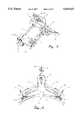
- FIG. 1is an isometric view of the preferred embodiment of a carriage probe having two transducers
- FIG. 2is an end elevation view of the preferred embodiment wherein the articulated frame of the carriage is shown in a flat or horizontal plane as when inspecting a plate weld;
- FIG. 3is an isometric view of the preferred embodiment of the carriage probe shown with the articulated frame in the inverted, articulated position;
- FIG. 4is an end elevation view of the preferred embodiment of the carriage probe shown in the working position on a tubular member
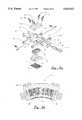
- FIG. 5is an exploded view of one embodiment of the transducer module
- FIG. 6is a cross section view of the transducer module depicted in FIG. 5;
- FIG. 6ais an exploded view of a second embodiment of the transducer module
- FIG. 6bis a cross section view of the second embodiment of the transducer module shown in FIG. 6a;
- FIG. 7is a top view of the transmitter and receiver coil arrangement on the upper side of the mylar separator sheet
- FIG. 8is a top view of the transmitter and receiver coil arrangement on the lower side of the mylar separator sheet
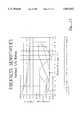
- FIG. 9is a chart for Lamb Wave frequencies vs. coil wire spacing for various material thickness
- FIG. 10is a chart for lamb wave efficiencies with various T/d ratios
- FIG. 11is a chart showing thickness to coil wire spacings at various sensitivity coefficients
- FIG. 12is a chart showing lamb wave phase velocity with regard to wire spacing
- FIG. 13is a second chart showing lamb wave phase velocity with regard to wire spacing
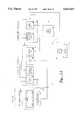
- FIG. 14is a block diagram of the essential electrical elements of the invention.
- FIG. 15is a simplified illustration of a two EMAT probe technique for inspecting pipe
- FIG. 16is graph indicating signal amplitude vs. time display as it would appear on an oscilloscope
- FIG. 17is a simplified illustration of a single EMAT probe technique for inspecting a pipe
- FIG. 18is a graph indicating signal amplitude vs. time display as it would appear on an oscilloscope
- FIG. 19is a process chart.
- the Electromagnetic Acoustic Transducer (EMAT) 4is a stand alone probe, or it can be carried onboard a carriage 2 which also includes a central body 10.
- the body 10houses a portion of the electronic circuitry 20,21 and provides the electrical connection points 22 for one or more transducers 4. These connections 22 further provide connection points for connecting an umbilical cord 81 between the carriage 2 and the main control chassis 71.
- An adjustable, articulated frame 12 as shown in FIGS. 1-4,is centrally attached to the body housing 10, providing a mounting platform for the transducers 4.
- the articulated frame 12allows the transducers 4 to be positioned in the flat plane, as seen in FIGS.
- the carriage 2may be propelled along the inspecting surface 6 or 7 by a set of magnetic wheels 14 driven by remotely controlled synchronous motors 16.
- the transducers 4are mounted on plates 18 which are also incrementally adjustable along either side of the articulated frame 12 extending outwardly from the central body housing 10.
- the transducers 4are secured to the mounting plates 18 and are adjustable laterally and vertically by a pair of jacking screws 24.
- a handle 26is also provided for leverage in extracting the carriage 2 from the inspection surface 6 or 7 due to the strong magnetic attraction of the transducers 4 and the magnetic wheels 14.
- the Electromagnetic Acoustic Transducers (EMAT) 4 as seen in FIGS. 5 and 6aare equipped with permanent magnets 28 that supply the magnetic field for the EMAT transduction system. These magnets 28 are attracted to the pipe 6 with a very large force. Therefore, it is essential that the transducer probes 4 be mounted on wheels 30,32 as shown in FIGS. 5 and 6a, so they can be moved along the length of the pipe 6 during inspection as best seen in FIG. 4.
- FIG. 6(b)shows the cross sectional end view of one embodiment 8 of the transducer whereby the lower surface of the magnet block 28 is curved in a manner to conform with the curvature of the pipe 6 under inspection.
- the wheels 32are camable and adjusted to the pipe radius by allen head screws 34.
- This embodiment 8has a main body portion 36 to which all components are attached.
- This embodimentutilizes a magnet module 38 for carrying a set of magnetic squares 28 arranged in pairs along three rows of twelve each, held in a semi-circular position by epoxy.
- the module 38is secured to the main body 35 by screws 40 passing through the main body 36 cover plate 42.
- the transmitter and receiver (transceiver) coils 44(a)(b)arranged in an interrelated manner as shown in FIGS.
- the coil wires 50are passed through a cavity in the main body 36 to an electrical jack connector 52 which is secured to the main body 36 by a retainer plate 54.
- the embodiment exemplified in FIG. 5is comprised of head and tail blocks 61,62 bolted to each other, and a pair of side rails 63 having cavities therein bolted to both the head and tail blocks 61,62.
- a block magnet 27is also disposed in a clamped relationship integrally within the confines of the head block 61, tail block 62 and side rails 63.
- the transmitter and receiver coils 44are disposed along the exposed face of the block magnet 27, the ends of which extend into cavities provided along the inside of the side rails 63 culminating in electrical jack connections 52 recessed into the ends.
- a wear sheet 47is also provided effectively covering the coils 44 and the block magnet 27.
- the wear sheet 47is springably secured to each of the side rails by bar clamps and is maintained in sliding contact with the pipe or plate 6 or 7.
- This transducer embodiment 4further utilizes a set of beveled vee wheels 30 attached to each end of the head and tail blocks 61,62.
- the block magnet 27 shown in FIG. 5 and 6is a Neodymium-Iron Boron, with an energy product of at least 35 MGO and is sometimes machined with a slight curve on one face.
- FIG. 6bA cross sectional view of the assembled interior of each of the transducer embodiments 4 or 8 shown in FIG. 6 and 6b.
- the section viewexposes the permanent magnets 28 which are individual metal disk slabs approximately 1/8 inch thick by 1/2 inch tall by 1/2 inch deep. There are three rows of 12 slabs across the width to make a total of 36 individual magnets. Each is magnetized along the 1/2 inch dimension and in a manner so that all north poles face the pipe.
- the most suitable material for the magnets for this applicationhas been found to be Neodymium-Iron-Boron with an energy product of 35 MGO.
- the internal construction of the EMAT's coils 44is very important because it determines the frequency of operation and the sensitivity to thickness changes. Since the magnetic field is applied over a 1.5 inch square area, the outer dimensions of the coils 44 were chosen to match this area. Since the invention is capable of operation with only one EMAT, it is important to note that the transmitter coil and the receiver coil are interposed in close proximity, as shown in FIGS. 7,8, housed together in the same space. In particular, it is essential that the coil wires 44a, 44b must be coincident so the clockwise and counterclockwise signals, which are launched together by the transmitter coil, 44(a) will coincide exactly when they meet under the receiver coil 44(b) after each trip around the circumference.
- FIG. 7shows the top surface of the Mylar with the transmitter conductor 44a drawn as a solid line along a meandering line path from a large soldering pad on the left to a small pad on the right.
- the receiver coil 44bis shown as a dashed line that follows the same path but joins a large pad on the right to a small pad on the left.
- FIG. 8shows the conductor path on the bottom surface as viewed from the top surface as if the Mylar were transparent.
- the transmitter coil 44ais depicted by a solid line and the receiver coil wire 44b by a dashed line.
- the top and bottom coilscan be connected to make a continuous circuit of the solid (transmitter) and dashed (receiver) lines with the big pads which act as the connection points for wires that connect the coils to the transmitter and receiver connectors 52 located on opposite sides of the EMAT.
- the most critical aspect of the EMAT coil arrangementis the dimensional spacing between the transmitter and receiver coils 44a, 44b arranged in a meandering shape.
- the dimension (d)sets the wave length of the Lamb wave that is launched or detected by the EMAT coil and determines the frequency of operation and the sensitivity to wall thickness changes in the inspection surface.
- the wave length, " ⁇ "is twice the coil wire spacing,"d".
- the optimum ratio of pipe wall thickness to wire spacing for the Lamb wave inspection of tubularsis between 1.3 and 1.4.
- a special EMAT coilis demanded for each wall thickness value.
- Table 1provides some guidance concerning the relationship between the transmitter and receiver coil wire 44a, 44b spacing, "d", (table 1) for the optimum EMAT coil to be used.
- the EMAT probe or scanner unitcomprises both the transducer unit, housing the permanent magnets 27,28, the transmitter and the receiver coils 44a, 44b, and the carriage unit 2.
- the carriage unit central bodyhouses the impedance matching network circuit and the preamplifier circuit 20,21.
- the impedance matching network 20is a transformer that matches a Matec power amplifier 70 located in the remote control chassis 71, to the one or two ohm impedance of the EMAT coils 44. This tuned transformer and its tuning capacitor may need to be changed if the frequency of operation is expected to be beyond the frequency normally supplied with the unit.
- the preamplifier 21is provided to aid in signal noise reduction. It has its own 110 volt AC power line but has no tuning or matching networks due to its broad bandwidth.
- a potentiometer mounted to the printed circuit boardcontrols the gain of this amplifier.
- the EMAT carriage 2is mounted on magnetized wheels 14, as shown in FIGS. 1-4, driven by remotely operated synchronous motors 16 at the Control Chassis 71 so that the carriage 2 can be driven externally along a pipe or plate during the inspection process. Both speed and direction of the motors 16 can be remotely controlled. It should be noted that the permanent magnets 27,28 built into the EMATs are very powerful and should be treated with respect.
- the entire probe unit 2 with its EMATS 4 or 8may be removed from a pipe or tank 6,7 by simply twisting the unit 2 sideways until it is crosswise of the pipe's axis then lifted off. To remove from a large, flatter surface such as large tanks 7 the articulated frame 12 should be allowed to fold by removing the cross brace, thus allowing the entire unit 2 to be lifted, breaking the magnetic field by leveraging from the side of the wheels 14.
- This instrumentationcomprises three main chassis 71,72,78 and some support elements that serve as input/output units. These parts are displayed in the block diagram shown in FIG. 14, and their functions are described below.
- the power supply chassis 60Besides supplying AC voltages to the system the power supply chassis 60 also converts 120 volt AC into the various DC voltages required by the system. Each DC voltage is fused separately and a pilot light on the front panel shows that voltage is available and the fuse is good if the light is on. Fuses are accessible on the back panel.
- the control chassis 71contains three printed circuit boards; the control network 64, a gain circuit card 66, a filter circuit 68, and the Matec power amplifier 70 that supplies the high current tone burst to the EMAT transmitter coils 44(a).
- the computer chassis 72is a 486 personal computer with a built in math co-processor chip and a 65 megabyte hard disc. It also has slots for 51/4 and 31/2 inch floppy discs so that data from particular inspections can be stored individually.
- the expansion slots for this computerhold an arbitrary wave form generator board 74 and an I/O board for producing the tone burst for the power amplifier plus a fast A/D board 76 for digitizing the RF signals coming from the EMAT receiver coil's 44(b) preamplifier 21.
- the CRT display and keyboard 78are connected to the computer through a 50 foot long umbilical cord 80 so that the display and controls can be accessible to an operator at a considerable distance from the instrumentation which may be housed in a trailer or in a van type vehicle.
- Another umbilical cord 81usually connects the control chassis 62 to the EMAT probe 2.
- the probe 2 and its EMATscould be operated equally as well by wireless communication.
- ultrasonic testingrelies on the measurement of the transit time of a high frequency sound pulse sent through the pipe directly under the transducer to measure the local wall thickness.
- Localized defectsare usually detected by inducing sound waves at an angle to the surface and observing the echoes that are reflected by nearby discontinuities.
- the present inventionutilizing EMATs 4 or 8, on the other hand, are particularly well suited for inducing low frequency waves which travel long distances from the transducer and hence inspect more material with each firing of the transmitter.
- the most effective of these special wavesare the Lamb Waves with frequencies normally below one megahertz. However, in certain situations other waves can be utilized to gain the desired result.
- the time of flight measurementsare used to deduce thickness variations, and echo reflections are used to detect localized flaws.
- the EMAT'S 4 or 8 coupling to the pipe wall 6is by electromagnetic induction without liquid couplant layers, signal amplitude measurements are more reliable; and the amplitude of the ultrasonic signals reaching a receiver can be used to betray the presence of defects that scatter energy from a sound beam which connects a transmitter with a receiver.
- This latter featureallows the detection of flaws oriented in any direction and is not limited to those flaw geometries that will reflect sound back to a particular receiving transducer.
- FIG. 17shows the pipe 6 and EMAT inspection geometry that is the most simple to implement and which gives 100% coverage of a circumferential belt around the pipe.
- the entire pipegets covered and all detectable flaws can be found at a scanning speed determined by the rate at which the transducer is moved. This speed can easily be in the range of a few feet per second.
- only one EMAT 4 or 8is shown because one magnet 27, or 28 and coil unit 44 can act as both a transmitter and receiver 44a, 44b.
- the EMATlaunches sound waves both to the right and left; therefore, a clockwise and a counterclockwise rotating pulse of ultrasonic energy moves around the pipe circumference. These waves return to the transmitter/receiver coils after a time given by the equation
- FIG. 18shows the appearance of an oscilloscope arranged to display the amplitude of signals received from the EMAT 4 as a function of time after triggering the transmitter. Signals appear at integral multiples of the time given in Equation (1) above as the sound wave makes multiple trips around the pipe circumference.
- the oscilloscope display, shown in FIG. 18,can be used in the following three ways to detect flaws in the circumferential path followed by the sound beam:
- the velocity V in Equation (1)depends on the frequency of the ultrasonic wave, the construction of the EMAT's coil 44 and the thickness of the pipe 6 or tank wall 7. It is this thickness dependence that allows thin spots anywhere along the circumferential belt to be detected. In particular, if there is a part of the circumference that is thinner by an amount Delta-T extending over a distance "s," the time to traverse the circumference given in Equation (1) will change to
- Vis the wave speed in the normal pipe or tank plate wall thickness T
- V'is the wave speed in the thin section of thickness T- ⁇ T.
- mis the mass of material missing at the thin spot.
- Mis the total mass of the wall interrogated by the sound beam (i.e., the pipe material density times the pipe circumference times the transducer width times the pipe wall thickness.
- Tis the wall thickness, and
- This techniquedoes not locate precisely where on the circumference of the pipe to look for the flaw, but instead, it tells the operator that a flaw exists at a certain location along the pipe length where additional inspections can then be concentrated.
- the sensitivity to small pits or crackscan only be determined by experience gained by comparisons of scans with various defects, and it is limited by the normal variations of the amplitude as the EMAT is scanned along nominal, flaw free samples of pipe. Because no compliant fluid is used and the EMATs are constructed to maintain a constant air gap between the coil and the surface due to the wheels 30 or 32, variations in the signal amplitude are usually very small during scanning along uniform, flaw-free pipes.
- the inspection method depicted in FIG. 15is well suited to small diameter, very uniform pipes such as seamless tubing.
- the longitudinal weld linecan introduce a wall thickening that shifts the transit time of the sound waves around the pipe and introduces localized reflectors that attenuate the signals and produce echo signals that appear like flaws. Since the weld is long and longitudinally oriented, very small variations in its geometrical characteristics produce strong, flaw-like indications.
- the transmitter and receivercan be separated and mounted on the pipe as shown in FIG. 15 or by simply electrically cross connecting the transmitter coil in one EMAT with the receiver coil in another EMAT. Such a configuration will produce the signal pattern shown in FIG.
- Mode 1Monitoring Signal 2. Measuring the arrival time and amplitude of Signal #2 provides an inspection of all the pipe circumference outside of the space between the EMATs because this signal has traversed the long counterclockwise path between transmitter and receiver coils 44a, 44b. If the weld line is not in this path the signals should be constant and appear like those found in a flaw free section of seamless tubing.
- Mode 2Monitoring. Signal 3. Measuring the arrival time of Signal #3 by itself gives information on the full circumference of the pipe with extra emphasis on the small region of length "S" that lies between the EMAT'S because Signal #3 has traversed this short section twice. If the transducers are positioned to straddle the weld line of an ERW pipe, Signal #3 will be dominated by the quality of the weld. In particular, changes in the arrival time of Signal #3 that are not in Signal #2 can be immediately interpreted as variations in the thickness at the weld caused by poor trimming of the weld flash during manufacture of the pipe. Similarly, variations in the amplitude of Signal #3 that are not in Signal #2 can be ascribed to reflecting defects in the weld. Thus, comparing Signals #2 and #3 leads to a concentrated inspection of the small section of pipe between the transducers.
- Mode 3Combining Signals #2 and #3. If the ratio of the amplitudes of Signals 2 and 3 are formed, the resulting quantity measures the attenuation of the sound wave that has passed through the distance "S" twice and is, therefore, able to detect the scattering of energy by defects in this small section of pipe. Likewise, the ratio of the two times of arrival can be related to time shifts caused by flaws that lie in the space "S.” Thus, the two ratios provide a sensitive inspection of the section of pipe marked by the length "S" in FIG. 15. By scanning the length of a pipe with the EMAT paired and located at different angular locations relative to the top of the pipe/ a very detailed and sensitive map of the flaws in the pipe can be developed.
- Equation 6is the change in the transit time ratio which can easily be graphed as a function of the distance along the pipe to expose the localized variations that an operator or alarm system can recognize as a flaw.
- Equation 6from which the severity of the flaw as measured by m/M can be deduced since the distance between transducers "S", the sound velocity "V”, the arrival time of the second signal t(2), and the sensitivity coefficient "C" are all known for a given inspection case.
- Lamb Wavediscussed above is the most often used wave form for the EMATS
- several alternative embodiments of the EMAT probe sensor capable of exciting and detecting other ultrasonic wave forms in metal parts and structureshave been researched and used successfully for particular inspection problems.
- the list and discussion belowis indicative of some of the special circumstances which may be encountered in detecting a specific flaw in a given material.
- SHEAR WAVE transducerslaunch and detect ultrasonic shear waves perpendicular to the surface of the part similar to conventional transducers; however, they are configured with an elongated spiral coil sandwiched between the face of the magnet and the part being inspected.
- ANGLE BEAM transducerslaunch and detect either shear or longitudinal waves at an angle to the surface.
- the EMATsutilize either tangential magnetic fields, produced by a pulsed electromagnet, or permanent magnets placed directly over the EMAT coil.
- the angleis controlled by the design of the coil and the frequency of operation. Maximum efficiency can be exploited if the shear wave is placed at a 30-degree angle to the surface.
- LAMB WAVESare generally used where the thickness of the metal is comparable with the wavelength of the sound wave.
- the Lamb wave formis in resonant mode with the sheet and exists only at a specific wavelength and frequency for a given material thickness.
- SHEAR HORIZONTAL WAVE transducersare shear waves with their polarization direction parallel to the surface of the part under inspection. This type wave form, seldom suffers from mode conversion, therefore, its echo patterns are clean and easily interpreted.
- the EMATis constructed of a simple elongated spiral coil and an array of small permanent magnets 28.
- FOCUSING EMATshave been developed by bending the wires of EMAT's 4 or 8 coils 44 in a manner which allows the waves to be focused on a particular location, either on the surface or below the surface of the part being inspected.
- FIG. 19outlines the following set up and operation procedures.
- Number of Cycles--between 5 and 10is good for a start . Sets the number of cycles in the tone burst.
- Transmitter Gategives the time duration of the tone burst as calculated by the computer from the frequency and the number of cycles. You have no choice.
- Main Bang Blank--Choosethe number of microseconds to keep the pre-amp off in order to keep the transmitter power out of the receiver. Should be larger than the Transmitter Gate but less than the arrival time of the first round trip signal.
- Waves to Avg--This number sets the number of wave forms that are averaged together to improve the signal-to-noise ratio. It should be set between three and ten.
- For the First window--The number of microseconds to delay the start of the display of the RF signal and the first window. This is like the delayed sweep control of an oscilloscope. This time delay can be estimated by calculating the circumference of the pipe ( ⁇ times the diameter) and dividing by the sound velocity of the Lamb Wave mode (0.19 in/ ⁇ sec) and then subtracting 10 or 20 ⁇ sec to start the "sweep" ahead of the signal.
- Start Xing windowat--The number of microseconds at which a small window that brackets a zero crossing in the middle of the signal will appear.
- the time of arrival (TOA) of this zero crossingis what the computer will use as the arrival time of the first signal. This number should be smaller than half a cycle of the RF frequency being used, i.e. less than 0.6 ⁇ sec for an 800 kHz signal.
- the computercan calculate the exact zero crossing time by a Least Squares Fit (LSF) technique, but this program is not used here. this value at 0.4 ⁇ sec.
- LSFLeast Squares Fit
- Tracking Window 1-The computer will keep the zero crossing centered in the zero xing window if you answer yes here (which you should do).
- Second WindowThese choices set the second window parameters and use the same instructions as above except the offset and the start xing win2 are delayed by the amount of time between the first and second signals. This is usually about 1/4 of the circumferential transit time calculated above.
- Press RETURN and the CRTwill activate the transmitter, and the CRT will display the first RF signal using the timing parameters chosen above. Since these choices were approximate, the following key strokes can be used to fine tune the windows and the signals; so they are optimized for making a pipe inspection. These key strokes are described in the HELP window which is available by pressing F1. To better position the signal on the screen:
- Page Upincreases the start of the time axis by 10 ⁇ sec.
- Page Downdecreases the time axis start by 10 ⁇ sec.
- the signal in the first windowshould be adjusted to cover about 90% of the vertical display.
- F4redraws the screen to eliminate dashed lines left behind by old window settings.
- the systemis now set and ready to run on a particular pipe. If the system is exited or if there is a power failure at this point, the window and gain settings so carefully established by the procedures described above will be lost and must be redetermined. To insure these settings, return to the CALIBRATE SYSTEM menu and use the CHANGE SYS. CONFIG., LOAD CONFIG. and WRITE CONFIG. instructions to give the particular configuration developed above a name and memory location, so they can be recalled and used whenever desired.
- the Pulse Repetition Frequencyis controlled by a screw driver adjustment on the rear panel of the control chassis. It is usually set at 50 Hz or a transmitter firing every 0.02 sec. If only 3 averages are used, it takes 0.06 sec. to record one measurement and, therefore, only 30 sec. to collect 512 measurements and cross the CRT display. If 10 averages are used, it takes 102 seconds to cross the screen. At a scan speed of 1 foot/sec. the CRT would display 102 feet of pipe with a measurement every 2.4 inches. If 10 feet were scanned in 30 sec. with 3 averages per measurement, there would be a measurement every 0.25 inches. Since the EMAT is 1.5 inches wide, a point flaw would affect the signal for 6 measurements. As explained previously, a flaw appears as a localized dip in the amplitude versus probe location graph.
- the lower coordinate system on the "Do Run” displayplots the "Time Of Arrival” (TOA) of the signal in the first window as deduced from the zero crossing window chosen.
- TOATime Of Arrival
- a deviation from the normal time of arrivalindicates a thickness variation somewhere in the circumferential belt being inspected.
- a thinningcauses the wave to increase its velocity so a thin region will cause the transit time to decrease.
- the second window graphdeviates from the first window graph, it indicates that a flaw lies in the space between EMATs . Simultaneous delineations in both windows are to be interpreted as arising from flaws outside the space between transducers.
- the graphsremain on the CRT for visual examination. To save and print the results of a run, press the ESC key, and menus will appear that allow the run to be labeled with an 8 character designation as well as a longer descriptor. The short label is used for recalling the run for further processing.
- Graph 2 Window RatiosThe raw data graphs developed during an inspection run are informative if studied by a skilled operator. However, to accentuate the variations that may be flaws, it is better to normalize the data by taking the ratios, described herein where the mathematical procedure is analyzed. Making the Graph 2 Window Run choice, presents the data as ratios of the amplitudes and arrival times which eliminates background variations and emphasizes the inspection of the space between the two transducers as described. Again, pressing F2 creates a hard copy print out of the 2 window data.
- E. EXITThe last choice on the CALIBRATE SYSTEM menu is EXIT. Making this choice brings up menus to help the operator save whatever data desired and insures a safe shut down of the system.
- the wire spacingswill range from 0.1 to 0.25 inches for tubulars in the 0.5 to 1.0 inch wall thickness range for tanks the spacings will range from 0.250 to 0.600 inches either of which is quite acceptable.
- FIGS. 10-13The above conclusions may be illustrated by the graphs depicted in FIGS. 10-13.
- FIG. 10indicates the relative efficiencies with which various Lamb wave modes are excited and detected as a function of the Pipe thickness to EMAT coil wire spacing
- FIG. 11depicts how sensitive the phase velocity of various Lamb wave modes are relative to thickness changes with the sensitivity coefficient shown unitless and proportional to the slop of the phase velocity versus thickness curves
- FIG. 12depicts the variation of the Lamb wave phase velocity with wall thickness to EMAT wire spacing ration (T/d), wherein the phase velocity is the speed that a phase feature such as a zero crossing moves through the material
- FIG. 13depicts the variation of the Lamb wave group with wall thickness to EMAT wire spacing, (T/d), wherein the group velocity is the speed that a tone burst or RF pulse moves through a dispersive material.
Landscapes
- Physics & Mathematics (AREA)
- Biochemistry (AREA)
- Health & Medical Sciences (AREA)
- Life Sciences & Earth Sciences (AREA)
- Chemical & Material Sciences (AREA)
- Analytical Chemistry (AREA)
- General Health & Medical Sciences (AREA)
- General Physics & Mathematics (AREA)
- Immunology (AREA)
- Pathology (AREA)
- Electromagnetism (AREA)
- Engineering & Computer Science (AREA)
- Signal Processing (AREA)
- Investigating Or Analyzing Materials By The Use Of Ultrasonic Waves (AREA)
Abstract
Description
TABLE I ______________________________________ Pipe dimensions expected to be encountered in refinery pipe inspections and the dimensions of probes and EMAT coils to be used on these pipes. WALL MAGNET. WIRE O.D. THICK. CURV. SPACE T/d SCHEDULE inches inches (Radius in.) "d" (in) Ratio ______________________________________ 40 2.375 0.154 1.5 0.14 1.2 80 " 0.218 " " 1.7 40 3.5 0.216 " " 1.7 80 " 0.300 " 0.20 1.5 40 4.5 0.237 2.5 " 1.2 80 " 0.337 " " 1.7 40 6.675 0.280 " " 1.4 80 " 0.432 " 0.30 1.4 40 8.625 0.322 " 0.20 1.6 80 " 0.500 " 0.30 1.7 40 10.75 0.365 " " 1.2 80 " 0.500 " " 1.7 ______________________________________
τ=πD/V Equation (1)
τ+Δτ=(πD-s) /V+s/V' Equation (2)
Δτ/τ=-(m/M)C Equation (3)
t(3)-t(2)=t(2){[t(3)/t(2)]-1}=2S/V Equation (4)t(3)/t(2)=2S/Vt(2)+1 Equation (5)
2(S-s)/V+2s/V'=(2S/V)[1-(m/M)C]=t'(3)/t(2) Equation (6)
Claims (39)
Priority Applications (1)
| Application Number | Priority Date | Filing Date | Title |
|---|---|---|---|
| US08/183,747US5619423A (en) | 1994-01-21 | 1994-01-21 | System, method and apparatus for the ultrasonic inspection of liquid filled tubulars and vessels |
Applications Claiming Priority (1)
| Application Number | Priority Date | Filing Date | Title |
|---|---|---|---|
| US08/183,747US5619423A (en) | 1994-01-21 | 1994-01-21 | System, method and apparatus for the ultrasonic inspection of liquid filled tubulars and vessels |
Publications (1)
| Publication Number | Publication Date |
|---|---|
| US5619423Atrue US5619423A (en) | 1997-04-08 |
Family
ID=22674129
Family Applications (1)
| Application Number | Title | Priority Date | Filing Date |
|---|---|---|---|
| US08/183,747Expired - Fee RelatedUS5619423A (en) | 1994-01-21 | 1994-01-21 | System, method and apparatus for the ultrasonic inspection of liquid filled tubulars and vessels |
Country Status (1)
| Country | Link |
|---|---|
| US (1) | US5619423A (en) |
Cited By (100)
| Publication number | Priority date | Publication date | Assignee | Title |
|---|---|---|---|---|
| US5907100A (en)* | 1997-06-30 | 1999-05-25 | Gas Research Institute | Method and system for detecting and displaying defects in piping |
| US5965818A (en)* | 1998-01-15 | 1999-10-12 | Shell Oil Company | Ultrasonic Lamb wave technique for measurement of pipe wall thickness at pipe supports |
| US6079273A (en)* | 1998-04-29 | 2000-06-27 | Mcdermott Technology, Inc. | EMAT inspection of header tube stubs |
| US6109108A (en)* | 1995-12-13 | 2000-08-29 | Ebara Corporation | Electromagnetic acoustic transducer EMAT and inspection system with EMAR |
| US6125705A (en)* | 1998-04-23 | 2000-10-03 | Bechtel Bwxt Idaho, Llc | Apparatus for the concurrent ultrasonic inspection of partially completed welds |
| US6125706A (en)* | 1997-07-25 | 2000-10-03 | Buttram; Jonathan D. | High temperature electromagnetic acoustic transducer |
| US6311558B1 (en) | 1998-03-23 | 2001-11-06 | The United States Of America As Represented By The Secretary Of Commerce | Ultrasonic strain gage using a motorized electromagnetic acoustic transducer |
| US6497159B1 (en) | 2000-06-12 | 2002-12-24 | Hydro-Quebec | Bracelet for moving ultrasonic sensors along a pipe |
| US6553838B2 (en)* | 2000-08-25 | 2003-04-29 | Em-Tech Llc | Detection of anomalies on railroad tracks |
| US6597973B1 (en) | 1999-10-01 | 2003-07-22 | Daniel M. Barich | Method and arrangement for inspection and requalification of lined vehicles used for transporting commodities and/or hazardous materials |
| US20040035208A1 (en)* | 2002-08-21 | 2004-02-26 | Diaz Aaron A. | Acoustic inspection device |
| US20040134970A1 (en)* | 2002-07-17 | 2004-07-15 | Den Boer Johannis Josephus | EMAT weld inspection |
| US6813949B2 (en)* | 2001-03-21 | 2004-11-09 | Mirant Corporation | Pipeline inspection system |
| US20040221652A1 (en)* | 2003-05-05 | 2004-11-11 | Flora John H. | Transducer guided wave electromagnetic acoustic |
| US6832183B1 (en) | 1999-10-01 | 2004-12-14 | General Electric Railcar Services Corporation | Method and database arrangement for inspection and requalification of vehicles used for transporting commodities and/or hazardous materials |
| US6955100B1 (en) | 1999-10-01 | 2005-10-18 | General Electric Railcar Services Corporation | Method and arrangement for inspection and requalification of vehicles used for transporting commodities and/or hazardous materials |
| US20050252296A1 (en)* | 2000-04-20 | 2005-11-17 | Vince Hock | System and method for accessing ferrous surfaces normally accessible only with special effort |
| US20060169022A1 (en)* | 2002-10-25 | 2006-08-03 | Nobuyoshi Sato | Device for measuring thickness of vessel steel plate |
| US20060230831A1 (en)* | 2002-12-17 | 2006-10-19 | Michael Berke | Method and device for sizing a crack in a workpiece using the ultrasonic pulse-echo technique |
| WO2006114485A1 (en)* | 2005-04-28 | 2006-11-02 | Roboplanet | Tool, sensor and device for a wall non-distructive control |
| DE202005017506U1 (en)* | 2005-11-07 | 2007-03-22 | Wangner Gmbh & Co. Kg | Apparatus for inspecting a sheet, e.g. a paper machine clothing |
| US7282663B2 (en) | 2002-07-29 | 2007-10-16 | Shell Oil Company | Forge welding process |
| US20080127731A1 (en)* | 2004-11-15 | 2008-06-05 | Independent Administrative Institution Japan Aerospace Exploration Agency | Ultrasonic Test Method And Ultrasonic Test Instrument Used For The Method |
| WO2007149605A3 (en)* | 2006-02-24 | 2008-07-31 | Battelle Memorial Institute | Methods and apparatus for multi-parameter acoustic signature inspection |
| US20090114026A1 (en)* | 2006-05-10 | 2009-05-07 | Robert Allan Simmons | Method and Apparatus for Conveying an Ultrasonic Sensor about an Outer Peripheral Surface of a Tube |
| US20090139335A1 (en)* | 2004-11-05 | 2009-06-04 | Michael Kroning | Device and Method for the Material Testing and/or Thickness Measurements of a Test Object That Contains at Least Fractions of Electrically Conductive and Ferromagnetic Material |
| US20090145249A1 (en)* | 2006-10-20 | 2009-06-11 | Dubbeldam Arthur J | Modular scanner assembly |
| US20090316531A1 (en)* | 2008-06-24 | 2009-12-24 | Alstom Technology Ltd | Portable ultrasonic scanner device for nondestructive testing |
| US20100019593A1 (en)* | 2004-08-12 | 2010-01-28 | Exro Technologies Inc. | Polyphasic multi-coil generator |
| DE102008054250A1 (en)* | 2008-10-24 | 2010-04-29 | Institut Dr. Foerster Gmbh & Co. Kg | Electromagnetic-acoustic transducer and ultrasonic test system with it |
| RU2390014C1 (en)* | 2009-03-17 | 2010-05-20 | Федеральное государственное учреждение "Научно-учебный центр "Сварка и контроль" при МГТУ им. Баумана" | Electromagnetic-acoustic transducer |
| RU2390013C1 (en)* | 2008-09-09 | 2010-05-20 | ООО "Компания "Нординкрафт" | Suspension bracket of electro-magnet acoustic converter |
| US20100185402A1 (en)* | 2009-01-20 | 2010-07-22 | National Railroad Passenger Corporation | Multi-probe rail scanning/encoder system and certified method of use thereof |
| US20100224001A1 (en)* | 2009-03-05 | 2010-09-09 | Alstom Technology Ltd | Low profile ultrasound inspection scanner |
| US20100326220A1 (en)* | 2009-06-26 | 2010-12-30 | Jireh Industries Ltd. | Modular scanner apparatus and probe holding apparatus for inspection |
| US20100327858A1 (en)* | 2009-06-26 | 2010-12-30 | James Simek | Pipeline Inspection Tool with Double Spiral EMAT Sensor Array |
| US20110088472A1 (en)* | 2007-11-30 | 2011-04-21 | Bundesanstalt Fuer Material-Forschung Und-Pruefung (BAM) | Device and method for the detection of composite defects |
| GB2479744A (en)* | 2010-04-20 | 2011-10-26 | Guided Ultrasonics Ltd | Ultrasonic transducer |
| US20110296922A1 (en)* | 2010-06-07 | 2011-12-08 | Syed Mohamed Ali | Emat for inspecting thick-section welds and weld overlays during the welding process |
| RU2441230C1 (en)* | 2010-10-25 | 2012-01-27 | Российская Федерация, От Имени Которой Выступает Министерство Образования И Науки Российской Федерации | Electromagnetic-acoustic transducer |
| US8106563B2 (en) | 2006-06-08 | 2012-01-31 | Exro Technologies Inc. | Polyphasic multi-coil electric device |
| EP2428650A1 (en)* | 2010-09-09 | 2012-03-14 | Alstom Technology Ltd | Inspection vehicle for the inspection of substantially cylindrical objects |
| US8365601B2 (en) | 2011-01-04 | 2013-02-05 | Saudi Arabian Oil Company | High precision corrosion monitoring sensor assembly and system |
| US20130076557A1 (en)* | 2010-04-22 | 2013-03-28 | Liverpool John Moores University | Electromagnetic sensor |
| RU2486502C2 (en)* | 2011-06-07 | 2013-06-27 | Федеральное государственное учреждение "Научно-учебный центр "Сварка и контроль" при МГТУ им. Н.Э. Баумана" | Method for ultrasonic examination of pipes |
| US20130180337A1 (en)* | 2011-12-14 | 2013-07-18 | Westinghouse Electric Company Llc | Signal processing of lamb wave data for pipe inspection |
| WO2013192536A1 (en)* | 2012-06-21 | 2013-12-27 | Spectrum Sales & Service, Llc | System and method for subsea inspection |
| WO2014149232A1 (en)* | 2013-03-15 | 2014-09-25 | Westinghouse Electric Company Llc | Ultrasonic examination of components with unknown surface geometries |
| JP2014194381A (en)* | 2013-03-29 | 2014-10-09 | Ihi Corp | Water level measurement device |
| US20150103630A1 (en)* | 2013-10-10 | 2015-04-16 | Avishai Bartov | Increasing signal to noise ratio of acoustic echoes by a group of spaced apart acoustic transciver arrays |
| US20150103628A1 (en)* | 2013-10-10 | 2015-04-16 | Avishai Bartov | Movable system for measuring a content of a bin |
| US20150103627A1 (en)* | 2013-10-10 | 2015-04-16 | Avishai Bartov | Group of spaced apart acoustic transciver arrays and a method for measuring a content of a bin |
| JP2015129656A (en)* | 2014-01-06 | 2015-07-16 | 株式会社アトックス | Travel type measuring apparatus |
| JP2015141177A (en)* | 2014-01-30 | 2015-08-03 | 株式会社堀場製作所 | Glow discharge spectroscopic analyzer, sample support and sample pressing electrode |
| JP2015179011A (en)* | 2014-03-19 | 2015-10-08 | 株式会社ジェイ・パワーシステムズ | Defect inspection method of metal pipe, defect inspection device of metal pipe and defect inspection program of metal pipe |
| US20150285058A1 (en)* | 2012-12-28 | 2015-10-08 | Halliburton Energy Services, Inc. | Method and apparatus for the downhole in-situ determination of the speed of sound in a formation fluid |
| US20150308981A1 (en)* | 2014-04-25 | 2015-10-29 | Bwxt Intech, Inc. | Inspection system for inspecting in-service piping or tubing |
| US9291520B2 (en) | 2011-08-12 | 2016-03-22 | Mueller International, Llc | Fire hydrant leak detector |
| US20160290965A1 (en)* | 2015-04-06 | 2016-10-06 | Fbs, Inc. | Long-range magnetostrictive ultrasonic guided wave scanner system and method |
| US9528903B2 (en) | 2014-10-01 | 2016-12-27 | Mueller International, Llc | Piezoelectric vibration sensor for fluid leak detection |
| US9849322B2 (en) | 2010-06-16 | 2017-12-26 | Mueller International, Llc | Infrastructure monitoring devices, systems, and methods |
| US9939344B2 (en) | 2012-10-26 | 2018-04-10 | Mueller International, Llc | Detecting leaks in a fluid distribution system |
| CN107966496A (en)* | 2017-11-22 | 2018-04-27 | 朱秋华 | A kind of positioning control system |
| US20180275671A1 (en)* | 2016-12-23 | 2018-09-27 | Gecko Robotics, Inc. | System, method, and apparatus to perform a surface inspection using real-time position information |
| US20190128854A1 (en)* | 2017-10-27 | 2019-05-02 | Olympus Scientific Solutions Americas Inc. | Scanner magnetic wheel system for close traction on pipes and pipe elbows |
| US10283857B2 (en) | 2016-02-12 | 2019-05-07 | Mueller International, Llc | Nozzle cap multi-band antenna assembly |
| US10305178B2 (en) | 2016-02-12 | 2019-05-28 | Mueller International, Llc | Nozzle cap multi-band antenna assembly |
| US10324066B1 (en)* | 2015-12-31 | 2019-06-18 | VeriPhase, Inc. | System and method for the improved analysis of ultrasonic weld data |
| EP2138838B1 (en)* | 2008-06-24 | 2019-07-03 | General Electric Technology GmbH | Ultrasonic inspection probe carrier system for performing nondestructive testing |
| CN110988121A (en)* | 2019-11-28 | 2020-04-10 | 合肥通用机械研究院有限公司 | Electromagnetic sound detection robot for storage tank |
| GB2577920A (en)* | 2018-10-10 | 2020-04-15 | Guided Ultrasonics Ltd | Determining thickness of an elongate or extended structure |
| US10636064B2 (en)* | 2015-12-31 | 2020-04-28 | VeriPhase, Inc. | Method for monetization of the data processing of ultrasonic scan data files |
| US10690585B2 (en) | 2014-10-09 | 2020-06-23 | General Electric Company | System and method for detecting an anomaly in a pipe assembly |
| RU2737226C1 (en)* | 2020-06-23 | 2020-11-26 | Алексей Алексеевич Абакумов | Electromagnetic-acoustic introscope for diagnostic inspection of casing strings and tubing of wells |
| US10859462B2 (en) | 2018-09-04 | 2020-12-08 | Mueller International, Llc | Hydrant cap leak detector with oriented sensor |
| US11081996B2 (en) | 2017-05-23 | 2021-08-03 | Dpm Technologies Inc. | Variable coil configuration system control, apparatus and method |
| US11135721B2 (en) | 2016-12-23 | 2021-10-05 | Gecko Robotics, Inc. | Apparatus for providing an interactive inspection map |
| CN113674884A (en)* | 2021-07-14 | 2021-11-19 | 岭澳核电有限公司 | Method, device, equipment and medium for determining defect position of voltage stabilizer of nuclear power station |
| US11307063B2 (en) | 2016-12-23 | 2022-04-19 | Gtc Law Group Pc & Affiliates | Inspection robot for horizontal tube inspection having vertically positionable sensor carriage |
| US11342656B2 (en) | 2018-12-28 | 2022-05-24 | Mueller International, Llc | Nozzle cap encapsulated antenna system |
| US11360052B2 (en)* | 2017-11-14 | 2022-06-14 | Siemens Energy Global GmbH & Co. KG | Testing of slot breech wedges of a generator rotor |
| US20220221429A1 (en)* | 2019-05-21 | 2022-07-14 | J. Van Beugen Beheer B.V. | Apparatus and method for pipeline inspection using emat generated shear waves |
| US20220268743A1 (en)* | 2019-11-01 | 2022-08-25 | Westinghouse Electric Company Llc | Ultrasonic testing probe, couplant delivery system, and ultrasonic testing apparatus |
| US11473993B2 (en) | 2019-05-31 | 2022-10-18 | Mueller International, Llc | Hydrant nozzle cap |
| US11506636B2 (en)* | 2018-03-22 | 2022-11-22 | Molex, Llc | System and method of submitting data from individual sensors over a shared cable |
| US11542690B2 (en) | 2020-05-14 | 2023-01-03 | Mueller International, Llc | Hydrant nozzle cap adapter |
| US20230031270A1 (en)* | 2021-07-27 | 2023-02-02 | Ecole De Technologie Superieure | Electromagnetic acoustic probe |
| US11573208B2 (en) | 2020-03-31 | 2023-02-07 | Olympus NDT Canada Inc. | Longitudinal and circumferential ultrasound scanner |
| US11708005B2 (en) | 2021-05-04 | 2023-07-25 | Exro Technologies Inc. | Systems and methods for individual control of a plurality of battery cells |
| US11722026B2 (en) | 2019-04-23 | 2023-08-08 | Dpm Technologies Inc. | Fault tolerant rotating electric machine |
| RU220373U1 (en)* | 2023-07-17 | 2023-09-11 | Общество с ограниченной ответственностью "Технический центр контроля и диагностики - Атомкомплект" | MONITORING DEVICE FOR CORNER WELDED JOINTS OF PIPELINES |
| WO2023163653A3 (en)* | 2022-02-25 | 2023-11-23 | Agency For Science, Technology And Research | Computer-implemented method for determining depth and location of localised thinning in plate structure |
| US11850726B2 (en) | 2021-04-20 | 2023-12-26 | Gecko Robotics, Inc. | Inspection robots with configurable interface plates |
| US20240094168A1 (en)* | 2022-09-21 | 2024-03-21 | King Fahd University Of Petroleum And Minerals | Method for detecting internal coating defects in pipe sample |
| US11967913B2 (en) | 2021-05-13 | 2024-04-23 | Exro Technologies Inc. | Method and apparatus to drive coils of a multiphase electric machine |
| US11971389B2 (en) | 2021-04-22 | 2024-04-30 | Gecko Robotics, Inc. | Systems, methods, and apparatus for ultra-sonic inspection of a surface |
| CN118858433A (en)* | 2024-09-19 | 2024-10-29 | 江西应用技术职业学院 | Ultrasonic detection equipment for rock fractures |
| US12162160B2 (en) | 2016-12-23 | 2024-12-10 | Gecko Robotics, Inc. | System, apparatus and method for improved location identification with prism |
| US12176836B2 (en) | 2018-09-05 | 2024-12-24 | Dpm Technologies Inc. | Systems and methods for intelligent energy storage and provisioning using an energy storage control system |
| US12358141B2 (en) | 2016-12-23 | 2025-07-15 | Gecko Robotics, Inc. | Systems, methods, and apparatus for providing interactive inspection map for inspection robot |
Citations (17)
| Publication number | Priority date | Publication date | Assignee | Title |
|---|---|---|---|---|
| US4092868A (en)* | 1976-10-12 | 1978-06-06 | Rockwell International Corporation | Ultrasonic inspection of pipelines |
| US4307615A (en)* | 1978-11-07 | 1981-12-29 | Studsvik Energiteknik Ab | Method and apparatus for transmitting and receiving electromagnetically generated and received ultrasonic pulses, primarily at non-destructive testing |
| US4314479A (en)* | 1978-11-07 | 1982-02-09 | Studsvik Energiteknik Ab | Method and apparatus for transmitting and receiving electromagnetically generated and received ultrasonic pulses |
| US4353257A (en)* | 1980-01-11 | 1982-10-12 | Her Majesty The Queen In Right Of Canada As Represented By The Minister Of National Defence | Nondestructive system for testing the thickness of boiler tubes in boilers |
| US4691572A (en)* | 1984-08-09 | 1987-09-08 | Shell Oil Company | Transducing device for contactless ultrasonic inspection of pipelines or tubings |
| US4793185A (en)* | 1986-04-24 | 1988-12-27 | Mannesmann Ag | Nondestructive testing |
| US4855676A (en)* | 1987-05-06 | 1989-08-08 | Atomic Energy Of Canada Limited | Ferromagnetic eddy current probe having transmit and receive coil assemblies |
| US4872130A (en)* | 1985-05-17 | 1989-10-03 | Pagano Dominick A | Automated in-line pipe inspection system |
| US4964054A (en)* | 1987-12-12 | 1990-10-16 | W. Schlafhorst & Co. | Method for changing sliver cans at a station of a textile machine |
| USH879H (en)* | 1989-06-30 | 1991-01-01 | The United States Of America As Represented By The Secretary Of The Navy | Method and device for inspecting circumferentially conducting materials |
| US5117182A (en)* | 1990-06-08 | 1992-05-26 | Atomic Energy Of Canada Limited | Ferromagnetic eddy current probe having multiple levels of magnetization |
| US5161413A (en)* | 1991-03-08 | 1992-11-10 | Westinghouse Electric Corp. | Apparatus and method for guided inspection of an object |
| US5429009A (en)* | 1993-05-20 | 1995-07-04 | Carnegie Mellon University | Robot with cruciform geometry |
| US5439157A (en)* | 1994-07-18 | 1995-08-08 | The Babcock & Wilcox Company | Automated butt weld inspection system |
| US5473953A (en)* | 1993-07-09 | 1995-12-12 | The United States Of America As Represented By The United States Department Of Energy | Device for inspecting vessel surfaces |
| US5503020A (en)* | 1994-07-01 | 1996-04-02 | Sonic Force Corporation | Electromagnetic acoustic transducer |
| US5535628A (en)* | 1994-11-14 | 1996-07-16 | Rohrback Cosasco Systems, Inc. | Ultrasonic scanner head and method |
- 1994
- 1994-01-21USUS08/183,747patent/US5619423A/ennot_activeExpired - Fee Related
Patent Citations (17)
| Publication number | Priority date | Publication date | Assignee | Title |
|---|---|---|---|---|
| US4092868A (en)* | 1976-10-12 | 1978-06-06 | Rockwell International Corporation | Ultrasonic inspection of pipelines |
| US4307615A (en)* | 1978-11-07 | 1981-12-29 | Studsvik Energiteknik Ab | Method and apparatus for transmitting and receiving electromagnetically generated and received ultrasonic pulses, primarily at non-destructive testing |
| US4314479A (en)* | 1978-11-07 | 1982-02-09 | Studsvik Energiteknik Ab | Method and apparatus for transmitting and receiving electromagnetically generated and received ultrasonic pulses |
| US4353257A (en)* | 1980-01-11 | 1982-10-12 | Her Majesty The Queen In Right Of Canada As Represented By The Minister Of National Defence | Nondestructive system for testing the thickness of boiler tubes in boilers |
| US4691572A (en)* | 1984-08-09 | 1987-09-08 | Shell Oil Company | Transducing device for contactless ultrasonic inspection of pipelines or tubings |
| US4872130A (en)* | 1985-05-17 | 1989-10-03 | Pagano Dominick A | Automated in-line pipe inspection system |
| US4793185A (en)* | 1986-04-24 | 1988-12-27 | Mannesmann Ag | Nondestructive testing |
| US4855676A (en)* | 1987-05-06 | 1989-08-08 | Atomic Energy Of Canada Limited | Ferromagnetic eddy current probe having transmit and receive coil assemblies |
| US4964054A (en)* | 1987-12-12 | 1990-10-16 | W. Schlafhorst & Co. | Method for changing sliver cans at a station of a textile machine |
| USH879H (en)* | 1989-06-30 | 1991-01-01 | The United States Of America As Represented By The Secretary Of The Navy | Method and device for inspecting circumferentially conducting materials |
| US5117182A (en)* | 1990-06-08 | 1992-05-26 | Atomic Energy Of Canada Limited | Ferromagnetic eddy current probe having multiple levels of magnetization |
| US5161413A (en)* | 1991-03-08 | 1992-11-10 | Westinghouse Electric Corp. | Apparatus and method for guided inspection of an object |
| US5429009A (en)* | 1993-05-20 | 1995-07-04 | Carnegie Mellon University | Robot with cruciform geometry |
| US5473953A (en)* | 1993-07-09 | 1995-12-12 | The United States Of America As Represented By The United States Department Of Energy | Device for inspecting vessel surfaces |
| US5503020A (en)* | 1994-07-01 | 1996-04-02 | Sonic Force Corporation | Electromagnetic acoustic transducer |
| US5439157A (en)* | 1994-07-18 | 1995-08-08 | The Babcock & Wilcox Company | Automated butt weld inspection system |
| US5535628A (en)* | 1994-11-14 | 1996-07-16 | Rohrback Cosasco Systems, Inc. | Ultrasonic scanner head and method |
Cited By (237)
| Publication number | Priority date | Publication date | Assignee | Title |
|---|---|---|---|---|
| US6109108A (en)* | 1995-12-13 | 2000-08-29 | Ebara Corporation | Electromagnetic acoustic transducer EMAT and inspection system with EMAR |
| US5907100A (en)* | 1997-06-30 | 1999-05-25 | Gas Research Institute | Method and system for detecting and displaying defects in piping |
| US6125706A (en)* | 1997-07-25 | 2000-10-03 | Buttram; Jonathan D. | High temperature electromagnetic acoustic transducer |
| US5965818A (en)* | 1998-01-15 | 1999-10-12 | Shell Oil Company | Ultrasonic Lamb wave technique for measurement of pipe wall thickness at pipe supports |
| US6311558B1 (en) | 1998-03-23 | 2001-11-06 | The United States Of America As Represented By The Secretary Of Commerce | Ultrasonic strain gage using a motorized electromagnetic acoustic transducer |
| US6502463B1 (en) | 1998-03-23 | 2003-01-07 | The United States Of America As Represented By The Secretary Of Commerce | Ultrasonic strain gage using a motorized electromagnetic acoustic transducer |
| US6125705A (en)* | 1998-04-23 | 2000-10-03 | Bechtel Bwxt Idaho, Llc | Apparatus for the concurrent ultrasonic inspection of partially completed welds |
| US6079273A (en)* | 1998-04-29 | 2000-06-27 | Mcdermott Technology, Inc. | EMAT inspection of header tube stubs |
| US6955100B1 (en) | 1999-10-01 | 2005-10-18 | General Electric Railcar Services Corporation | Method and arrangement for inspection and requalification of vehicles used for transporting commodities and/or hazardous materials |
| US6597973B1 (en) | 1999-10-01 | 2003-07-22 | Daniel M. Barich | Method and arrangement for inspection and requalification of lined vehicles used for transporting commodities and/or hazardous materials |
| US6832183B1 (en) | 1999-10-01 | 2004-12-14 | General Electric Railcar Services Corporation | Method and database arrangement for inspection and requalification of vehicles used for transporting commodities and/or hazardous materials |
| US20080148876A1 (en)* | 2000-04-20 | 2008-06-26 | Vince Hock | System and method for accessing ferrous surfaces normally accessible only with special effort |
| US7296488B2 (en) | 2000-04-20 | 2007-11-20 | United States Of America As Represented By The Secretary Of The Army | System and method for accessing ferrous surfaces normally accessible only with special effort |
| US20050252296A1 (en)* | 2000-04-20 | 2005-11-17 | Vince Hock | System and method for accessing ferrous surfaces normally accessible only with special effort |
| US6497159B1 (en) | 2000-06-12 | 2002-12-24 | Hydro-Quebec | Bracelet for moving ultrasonic sensors along a pipe |
| US6553838B2 (en)* | 2000-08-25 | 2003-04-29 | Em-Tech Llc | Detection of anomalies on railroad tracks |
| US6813949B2 (en)* | 2001-03-21 | 2004-11-09 | Mirant Corporation | Pipeline inspection system |
| US20040134970A1 (en)* | 2002-07-17 | 2004-07-15 | Den Boer Johannis Josephus | EMAT weld inspection |
| US6896171B2 (en)* | 2002-07-17 | 2005-05-24 | Shell Oil Company | EMAT weld inspection |
| US7282663B2 (en) | 2002-07-29 | 2007-10-16 | Shell Oil Company | Forge welding process |
| US20040035208A1 (en)* | 2002-08-21 | 2004-02-26 | Diaz Aaron A. | Acoustic inspection device |
| US6938488B2 (en) | 2002-08-21 | 2005-09-06 | Battelle Memorial Institute | Acoustic inspection device |
| WO2004019028A3 (en)* | 2002-08-21 | 2005-02-17 | Battelle Memorial Institute | Device for acoustic inspection of container content |
| US7854168B2 (en) | 2002-10-25 | 2010-12-21 | Asahi Kasei Engineering Corporation | Thickness measuring device for vessel steel plate |
| US20060169022A1 (en)* | 2002-10-25 | 2006-08-03 | Nobuyoshi Sato | Device for measuring thickness of vessel steel plate |
| US20090114025A1 (en)* | 2002-10-25 | 2009-05-07 | Asahi Kasei Engineering Corporation | Thickness measuring device for vessel steel plate |
| US7513161B2 (en)* | 2002-10-25 | 2009-04-07 | Asahi Kasei Engineering Corporation | Device for measuring thickness of vessel steel plate |
| US20060230831A1 (en)* | 2002-12-17 | 2006-10-19 | Michael Berke | Method and device for sizing a crack in a workpiece using the ultrasonic pulse-echo technique |
| US6920792B2 (en)* | 2003-05-05 | 2005-07-26 | John H. Flora | Transducer guided wave electromagnetic acoustic |
| US20040221652A1 (en)* | 2003-05-05 | 2004-11-11 | Flora John H. | Transducer guided wave electromagnetic acoustic |
| US8614529B2 (en) | 2004-08-12 | 2013-12-24 | Exro Technologies, Inc. | Polyphasic multi-coil electric device |
| US8212445B2 (en) | 2004-08-12 | 2012-07-03 | Exro Technologies Inc. | Polyphasic multi-coil electric device |
| US20100019593A1 (en)* | 2004-08-12 | 2010-01-28 | Exro Technologies Inc. | Polyphasic multi-coil generator |
| US9685827B2 (en) | 2004-08-12 | 2017-06-20 | Exro Technologies Inc. | Polyphasic multi-coil electric device |
| US8037764B2 (en)* | 2004-11-05 | 2011-10-18 | Fraunhofer-Gesellschaft zur Förderung der angewandten Forschung e.V. | Device and method for the material testing and/or thickness measurements of a test object that contains at least fractions of electrically conductive and ferromagnetic material |
| US20090139335A1 (en)* | 2004-11-05 | 2009-06-04 | Michael Kroning | Device and Method for the Material Testing and/or Thickness Measurements of a Test Object That Contains at Least Fractions of Electrically Conductive and Ferromagnetic Material |
| US20080127731A1 (en)* | 2004-11-15 | 2008-06-05 | Independent Administrative Institution Japan Aerospace Exploration Agency | Ultrasonic Test Method And Ultrasonic Test Instrument Used For The Method |
| US7721606B2 (en)* | 2004-11-15 | 2010-05-25 | Independent Administrative Institution Japan Aerospace Exploration Agency | Ultrasonic test method and ultrasonic test instrument used for the method |
| US20090301203A1 (en)* | 2005-04-28 | 2009-12-10 | Roboplanet | Tool, Sensor, and Device for a Wall Non-Distructive Control |
| WO2006114485A1 (en)* | 2005-04-28 | 2006-11-02 | Roboplanet | Tool, sensor and device for a wall non-distructive control |
| DE202005017506U1 (en)* | 2005-11-07 | 2007-03-22 | Wangner Gmbh & Co. Kg | Apparatus for inspecting a sheet, e.g. a paper machine clothing |
| WO2007149605A3 (en)* | 2006-02-24 | 2008-07-31 | Battelle Memorial Institute | Methods and apparatus for multi-parameter acoustic signature inspection |
| US20090114026A1 (en)* | 2006-05-10 | 2009-05-07 | Robert Allan Simmons | Method and Apparatus for Conveying an Ultrasonic Sensor about an Outer Peripheral Surface of a Tube |
| US8146430B2 (en) | 2006-05-10 | 2012-04-03 | Jireh Industries Ltd. | Method and apparatus for conveying an ultrasonic sensor about an outer peripheral surface of a tube |
| US9584056B2 (en) | 2006-06-08 | 2017-02-28 | Exro Technologies Inc. | Polyphasic multi-coil generator |
| US8106563B2 (en) | 2006-06-08 | 2012-01-31 | Exro Technologies Inc. | Polyphasic multi-coil electric device |
| US20090145249A1 (en)* | 2006-10-20 | 2009-06-11 | Dubbeldam Arthur J | Modular scanner assembly |
| US20110088472A1 (en)* | 2007-11-30 | 2011-04-21 | Bundesanstalt Fuer Material-Forschung Und-Pruefung (BAM) | Device and method for the detection of composite defects |
| US8490493B2 (en)* | 2007-11-30 | 2013-07-23 | Bundesanstalt fuer Materialforschung und-pruefung (BAM) | Device and method for the detection of composite defects |
| EP2138838B1 (en)* | 2008-06-24 | 2019-07-03 | General Electric Technology GmbH | Ultrasonic inspection probe carrier system for performing nondestructive testing |
| EP2138837A3 (en)* | 2008-06-24 | 2011-04-13 | Alstom Technology Ltd | Portable ultrasonic scanner device for nondestructive testing |
| US7984650B2 (en) | 2008-06-24 | 2011-07-26 | Alstom Technology Ltd | Portable ultrasonic scanner device for nondestructive testing |
| US20090316531A1 (en)* | 2008-06-24 | 2009-12-24 | Alstom Technology Ltd | Portable ultrasonic scanner device for nondestructive testing |
| RU2390013C1 (en)* | 2008-09-09 | 2010-05-20 | ООО "Компания "Нординкрафт" | Suspension bracket of electro-magnet acoustic converter |
| DE102008054250A1 (en)* | 2008-10-24 | 2010-04-29 | Institut Dr. Foerster Gmbh & Co. Kg | Electromagnetic-acoustic transducer and ultrasonic test system with it |
| US8789422B2 (en) | 2008-10-24 | 2014-07-29 | Institut Dr. Foerster Gmbh & Co. Kg | Electromagnetic-acoustic transducer and ultrasonic test system having the same |
| US9128034B2 (en) | 2009-01-20 | 2015-09-08 | National Railrod Passenger Corporation | Multi-probe rail scanning/encoder system and certified method of use thereof |
| US20100185402A1 (en)* | 2009-01-20 | 2010-07-22 | National Railroad Passenger Corporation | Multi-probe rail scanning/encoder system and certified method of use thereof |
| US8196469B2 (en)* | 2009-01-20 | 2012-06-12 | National Railroad Passenger Corporation | Multi-probe rail scanning/encoder system and certified method of use thereof |
| US8347724B2 (en) | 2009-03-05 | 2013-01-08 | Alstom Technology Ltd | Low profile ultrasound inspection scanner |
| US8813567B2 (en) | 2009-03-05 | 2014-08-26 | Alstom Technology Ltd | Low profile ultrasound inspection scanner |
| US20100224001A1 (en)* | 2009-03-05 | 2010-09-09 | Alstom Technology Ltd | Low profile ultrasound inspection scanner |
| WO2010101670A1 (en)* | 2009-03-05 | 2010-09-10 | Alstom Technology Ltd | Low profile ultrasound inspection scanner |
| RU2390014C1 (en)* | 2009-03-17 | 2010-05-20 | Федеральное государственное учреждение "Научно-учебный центр "Сварка и контроль" при МГТУ им. Баумана" | Electromagnetic-acoustic transducer |
| US20100326220A1 (en)* | 2009-06-26 | 2010-12-30 | Jireh Industries Ltd. | Modular scanner apparatus and probe holding apparatus for inspection |
| US8646347B2 (en) | 2009-06-26 | 2014-02-11 | Jireh Industries Ltd. | Modular scanner apparatus and probe holding apparatus for inspection |
| US8319494B2 (en) | 2009-06-26 | 2012-11-27 | Tdw Delaware Inc. | Pipeline inspection tool with double spiral EMAT sensor array |
| US20100327858A1 (en)* | 2009-06-26 | 2010-12-30 | James Simek | Pipeline Inspection Tool with Double Spiral EMAT Sensor Array |
| GB2479744A (en)* | 2010-04-20 | 2011-10-26 | Guided Ultrasonics Ltd | Ultrasonic transducer |
| US9065038B2 (en) | 2010-04-20 | 2015-06-23 | Guided Ultrasonics Ltd. | Transducer assembly |
| WO2011131954A3 (en)* | 2010-04-20 | 2012-05-18 | Guided Ultrasonics Ltd. | Ultrasonic transducer with wear plate |
| US20130076557A1 (en)* | 2010-04-22 | 2013-03-28 | Liverpool John Moores University | Electromagnetic sensor |
| US20110296922A1 (en)* | 2010-06-07 | 2011-12-08 | Syed Mohamed Ali | Emat for inspecting thick-section welds and weld overlays during the welding process |
| US9861848B2 (en) | 2010-06-16 | 2018-01-09 | Mueller International, Llc | Infrastructure monitoring devices, systems, and methods |
| US11590376B2 (en) | 2010-06-16 | 2023-02-28 | Mueller International, Llc | Infrastructure monitoring devices, systems, and methods |
| US10857403B2 (en) | 2010-06-16 | 2020-12-08 | Mueller International, Llc | Infrastructure monitoring devices, systems, and methods |
| US10881888B2 (en) | 2010-06-16 | 2021-01-05 | Mueller International, Llc | Infrastructure monitoring devices, systems, and methods |
| US9849322B2 (en) | 2010-06-16 | 2017-12-26 | Mueller International, Llc | Infrastructure monitoring devices, systems, and methods |
| US20120060611A1 (en)* | 2010-09-09 | 2012-03-15 | Alstom Technology Ltd | Inspection vehicle for the inspection of substantially cylindrical objects |
| US9291603B2 (en)* | 2010-09-09 | 2016-03-22 | Alstom Technology Ltd | Inspection vehicle for the inspection of substantially cylindrical objects |
| EP2428650B1 (en) | 2010-09-09 | 2017-12-20 | General Electric Technology GmbH | Inspection vehicle for the inspection of substantially cylindrical objects |
| CN102410843B (en)* | 2010-09-09 | 2017-08-18 | 通用电器技术有限公司 | The inspection vehicle of generally cylindrical object for checking |
| EP2428650A1 (en)* | 2010-09-09 | 2012-03-14 | Alstom Technology Ltd | Inspection vehicle for the inspection of substantially cylindrical objects |
| RU2441230C1 (en)* | 2010-10-25 | 2012-01-27 | Российская Федерация, От Имени Которой Выступает Министерство Образования И Науки Российской Федерации | Electromagnetic-acoustic transducer |
| US8365601B2 (en) | 2011-01-04 | 2013-02-05 | Saudi Arabian Oil Company | High precision corrosion monitoring sensor assembly and system |
| RU2486502C2 (en)* | 2011-06-07 | 2013-06-27 | Федеральное государственное учреждение "Научно-учебный центр "Сварка и контроль" при МГТУ им. Н.Э. Баумана" | Method for ultrasonic examination of pipes |
| US10386257B2 (en) | 2011-08-12 | 2019-08-20 | Mueller International, Llc | Enclosure for leak detector |
| US9772250B2 (en) | 2011-08-12 | 2017-09-26 | Mueller International, Llc | Leak detector and sensor |
| US9291520B2 (en) | 2011-08-12 | 2016-03-22 | Mueller International, Llc | Fire hydrant leak detector |
| US11680865B2 (en) | 2011-08-12 | 2023-06-20 | Mueller International, Llc | Leak detection in water distribution systems using acoustic signals |
| US10175135B2 (en) | 2011-08-12 | 2019-01-08 | Mueller International, Llc | Leak detector |
| US9593999B2 (en) | 2011-08-12 | 2017-03-14 | Mueller International, Llc | Enclosure for leak detector |
| US11630021B2 (en) | 2011-08-12 | 2023-04-18 | Mueller International, Llc | Enclosure for leak detector |
| US20130180337A1 (en)* | 2011-12-14 | 2013-07-18 | Westinghouse Electric Company Llc | Signal processing of lamb wave data for pipe inspection |
| EP2791628A4 (en)* | 2011-12-14 | 2015-08-05 | Westinghouse Electric Corp | SIGNAL PROCESSING OF LAMBDA WAVE DATA TO TEST PIPES |
| US9347851B2 (en)* | 2011-12-14 | 2016-05-24 | Westinghouse Electric Company Llc | Signal processing of lamb wave data for pipe inspection |
| WO2013192536A1 (en)* | 2012-06-21 | 2013-12-27 | Spectrum Sales & Service, Llc | System and method for subsea inspection |
| EP2864773A4 (en)* | 2012-06-21 | 2016-05-25 | Oceaneering Int Inc | UNDERWATER INSPECTION SYSTEM AND METHOD |
| US9903839B2 (en) | 2012-06-21 | 2018-02-27 | Oceaneering International, Inc. | System and method for subsea inspection |
| US9939344B2 (en) | 2012-10-26 | 2018-04-10 | Mueller International, Llc | Detecting leaks in a fluid distribution system |
| US10352908B2 (en)* | 2012-12-28 | 2019-07-16 | Halliburton Energy Services, Inc. | Method and apparatus for the downhole in-situ determination of the speed of sound in a formation fluid |
| US20150285058A1 (en)* | 2012-12-28 | 2015-10-08 | Halliburton Energy Services, Inc. | Method and apparatus for the downhole in-situ determination of the speed of sound in a formation fluid |
| WO2014149232A1 (en)* | 2013-03-15 | 2014-09-25 | Westinghouse Electric Company Llc | Ultrasonic examination of components with unknown surface geometries |
| JP2014194381A (en)* | 2013-03-29 | 2014-10-09 | Ihi Corp | Water level measurement device |
| US9952318B2 (en)* | 2013-10-10 | 2018-04-24 | Apm Automation Solutions Ltd | Group of spaced apart acoustic transceiver arrays and a method for measuring a content of a bin |
| US20150103630A1 (en)* | 2013-10-10 | 2015-04-16 | Avishai Bartov | Increasing signal to noise ratio of acoustic echoes by a group of spaced apart acoustic transciver arrays |
| US9952083B2 (en)* | 2013-10-10 | 2018-04-24 | Apm Automation Solutions Ltd | Movable system for measuring a content of a bin |
| US20150103628A1 (en)* | 2013-10-10 | 2015-04-16 | Avishai Bartov | Movable system for measuring a content of a bin |
| US9952084B2 (en)* | 2013-10-10 | 2018-04-24 | Apm Automation Solutions Ltd | Increasing signal to noise ratio of acoustic echoes by a group of spaced apart acoustic transceiver arrays |
| US20150103627A1 (en)* | 2013-10-10 | 2015-04-16 | Avishai Bartov | Group of spaced apart acoustic transciver arrays and a method for measuring a content of a bin |
| JP2015129656A (en)* | 2014-01-06 | 2015-07-16 | 株式会社アトックス | Travel type measuring apparatus |
| JP2015141177A (en)* | 2014-01-30 | 2015-08-03 | 株式会社堀場製作所 | Glow discharge spectroscopic analyzer, sample support and sample pressing electrode |
| JP2015179011A (en)* | 2014-03-19 | 2015-10-08 | 株式会社ジェイ・パワーシステムズ | Defect inspection method of metal pipe, defect inspection device of metal pipe and defect inspection program of metal pipe |
| US20150308981A1 (en)* | 2014-04-25 | 2015-10-29 | Bwxt Intech, Inc. | Inspection system for inspecting in-service piping or tubing |
| US9638670B2 (en)* | 2014-04-25 | 2017-05-02 | Bwxt Intech, Inc. | Inspection system for inspecting in-service piping or tubing |
| US9528903B2 (en) | 2014-10-01 | 2016-12-27 | Mueller International, Llc | Piezoelectric vibration sensor for fluid leak detection |
| US10690585B2 (en) | 2014-10-09 | 2020-06-23 | General Electric Company | System and method for detecting an anomaly in a pipe assembly |
| US20160290965A1 (en)* | 2015-04-06 | 2016-10-06 | Fbs, Inc. | Long-range magnetostrictive ultrasonic guided wave scanner system and method |
| US9915632B2 (en)* | 2015-04-06 | 2018-03-13 | Fbs, Inc. | Long-range magnetostrictive ultrasonic guided wave scanner system and method |
| US10636064B2 (en)* | 2015-12-31 | 2020-04-28 | VeriPhase, Inc. | Method for monetization of the data processing of ultrasonic scan data files |
| US10324066B1 (en)* | 2015-12-31 | 2019-06-18 | VeriPhase, Inc. | System and method for the improved analysis of ultrasonic weld data |
| US10283857B2 (en) | 2016-02-12 | 2019-05-07 | Mueller International, Llc | Nozzle cap multi-band antenna assembly |
| US11527821B2 (en) | 2016-02-12 | 2022-12-13 | Mueller International, Llc | Nozzle cap assembly |
| US10305178B2 (en) | 2016-02-12 | 2019-05-28 | Mueller International, Llc | Nozzle cap multi-band antenna assembly |
| US11837782B2 (en) | 2016-02-12 | 2023-12-05 | Mueller International, Llc | Nozzle cap assembly |
| US11652284B2 (en) | 2016-02-12 | 2023-05-16 | Mueller International, Llc | Nozzle cap assembly |
| US11469494B2 (en) | 2016-02-12 | 2022-10-11 | Mueller International, Llc | Nozzle cap multi-band antenna assembly |
| US11336004B2 (en) | 2016-02-12 | 2022-05-17 | Mueller International, Llc | Nozzle cap multi-band antenna assembly |
| US12212053B2 (en) | 2016-02-12 | 2025-01-28 | Mueller International, Llc | Nozzle cap multi-band antenna assembly |
| US11518030B2 (en) | 2016-12-23 | 2022-12-06 | Gecko Robotics, Inc. | System, apparatus and method for providing an interactive inspection map |
| US12061483B2 (en) | 2016-12-23 | 2024-08-13 | Gecko Robotics, Inc. | System, method, and apparatus for inspecting a surface |
| US12358141B2 (en) | 2016-12-23 | 2025-07-15 | Gecko Robotics, Inc. | Systems, methods, and apparatus for providing interactive inspection map for inspection robot |
| US10884423B2 (en) | 2016-12-23 | 2021-01-05 | Gecko Robotics, Inc. | System, method, and apparatus for acoustic and magnetic induction thickness inspection of a material on a substrate |
| US11872707B2 (en) | 2016-12-23 | 2024-01-16 | Gecko Robotics, Inc. | Systems and methods for driving an inspection robot with motor having magnetic shielding |
| US10795373B2 (en)* | 2016-12-23 | 2020-10-06 | Gecko Robotics, Inc. | Inspection robot having a number of horizontally displaced sensor sleds |
| US10895878B2 (en) | 2016-12-23 | 2021-01-19 | Gecko Robotics, Inc. | Inspection robot having self-aligning wheels |
| US10942522B2 (en) | 2016-12-23 | 2021-03-09 | Gecko Robotics, Inc. | System, method, and apparatus for correlating inspection data and image data |
| US11892322B2 (en) | 2016-12-23 | 2024-02-06 | Gecko Robotics, Inc. | Inspection robot for horizontal tube inspection having sensor carriage |
| US11740635B2 (en) | 2016-12-23 | 2023-08-29 | Gecko Robotics, Inc. | System, method, and apparatus for acoustic inspection of a surface |
| US11135721B2 (en) | 2016-12-23 | 2021-10-05 | Gecko Robotics, Inc. | Apparatus for providing an interactive inspection map |
| US11144063B2 (en) | 2016-12-23 | 2021-10-12 | Gecko Robotics, Inc. | System, method, and apparatus for inspecting a surface |
| US11148292B2 (en) | 2016-12-23 | 2021-10-19 | Gecko Robotics, Inc. | Controller for inspection robot traversing an obstacle |
| US11157012B2 (en) | 2016-12-23 | 2021-10-26 | Gecko Robotics, Inc. | System, method, and apparatus for an inspection robot performing an ultrasonic inspection |
| US11157013B2 (en) | 2016-12-23 | 2021-10-26 | Gecko Robotics, Inc. | Inspection robot having serial sensor operations |
| US12013705B2 (en) | 2016-12-23 | 2024-06-18 | Gecko Robotics, Inc. | Payload with adjustable and rotatable sensor sleds for robotic inspection |
| US11307063B2 (en) | 2016-12-23 | 2022-04-19 | Gtc Law Group Pc & Affiliates | Inspection robot for horizontal tube inspection having vertically positionable sensor carriage |
| US10739779B2 (en) | 2016-12-23 | 2020-08-11 | Gecko Robotics, Inc. | Inspection robot having replaceable sensor sled portions |
| US20180275674A1 (en)* | 2016-12-23 | 2018-09-27 | Gecko Robotics, Inc. | Inspection robot having a number of horizontally displaced sensors |
| US11673272B2 (en) | 2016-12-23 | 2023-06-13 | Gecko Robotics, Inc. | Inspection robot with stability assist device |
| US11385650B2 (en) | 2016-12-23 | 2022-07-12 | Gecko Robotics, Inc. | Inspection robot having replaceable sensor sled portions |
| US11669100B2 (en) | 2016-12-23 | 2023-06-06 | Gecko Robotics, Inc. | Inspection robot having a laser profiler |
| US11648671B2 (en) | 2016-12-23 | 2023-05-16 | Gecko Robotics, Inc. | Systems, methods, and apparatus for tracking location of an inspection robot |
| US10481608B2 (en)* | 2016-12-23 | 2019-11-19 | Gecko Robotics, Inc. | System, method, and apparatus to perform a surface inspection using real-time position information |
| US11429109B2 (en) | 2016-12-23 | 2022-08-30 | Gecko Robotics, Inc. | System, method, and apparatus to perform a surface inspection using real-time position information |
| US10698412B2 (en) | 2016-12-23 | 2020-06-30 | Gecko Robotics, Inc. | Inspection robot with couplant chamber disposed within sled for acoustic coupling |
| US20180275671A1 (en)* | 2016-12-23 | 2018-09-27 | Gecko Robotics, Inc. | System, method, and apparatus to perform a surface inspection using real-time position information |
| US11504850B2 (en) | 2016-12-23 | 2022-11-22 | Gecko Robotics, Inc. | Inspection robot and methods thereof for responding to inspection data in real time |
| US10534365B2 (en) | 2016-12-23 | 2020-01-14 | Gecko Robotics, Inc. | Inspection robot having vertically distributed payloads with horizontally distributed sensor sleds |
| US11511426B2 (en) | 2016-12-23 | 2022-11-29 | Gecko Robotics, Inc. | System, method, and apparatus for rapid development of an inspection scheme for an inspection robot |
| US11511427B2 (en) | 2016-12-23 | 2022-11-29 | Gecko Robotics, Inc. | System, apparatus and method for providing an inspection map |
| US12061484B2 (en) | 2016-12-23 | 2024-08-13 | Gecko Robotics, Inc. | Inspection robot having adjustable resolution |
| US11518031B2 (en) | 2016-12-23 | 2022-12-06 | Gecko Robotics, Inc. | System and method for traversing an obstacle with an inspection robot |
| US11565417B2 (en) | 2016-12-23 | 2023-01-31 | Gecko Robotics, Inc. | System and method for configuring an inspection robot for inspecting an inspection surface |
| US11529735B2 (en) | 2016-12-23 | 2022-12-20 | Gecko Robotics, Inc. | Inspection robots with a multi-function piston connecting a drive module to a central chassis |
| US12162160B2 (en) | 2016-12-23 | 2024-12-10 | Gecko Robotics, Inc. | System, apparatus and method for improved location identification with prism |
| US11081996B2 (en) | 2017-05-23 | 2021-08-03 | Dpm Technologies Inc. | Variable coil configuration system control, apparatus and method |
| US20190128854A1 (en)* | 2017-10-27 | 2019-05-02 | Olympus Scientific Solutions Americas Inc. | Scanner magnetic wheel system for close traction on pipes and pipe elbows |
| US10883970B2 (en)* | 2017-10-27 | 2021-01-05 | Olympus America Inc. | Scanner magnetic wheel system for close traction on pipes and pipe elbows |
| US11360052B2 (en)* | 2017-11-14 | 2022-06-14 | Siemens Energy Global GmbH & Co. KG | Testing of slot breech wedges of a generator rotor |
| CN107966496A (en)* | 2017-11-22 | 2018-04-27 | 朱秋华 | A kind of positioning control system |
| US11506636B2 (en)* | 2018-03-22 | 2022-11-22 | Molex, Llc | System and method of submitting data from individual sensors over a shared cable |
| US11692901B2 (en) | 2018-09-04 | 2023-07-04 | Mueller International, Llc | Hydrant cap leak detector with oriented sensor |
| US11422054B2 (en) | 2018-09-04 | 2022-08-23 | Mueller International, Llc | Hydrant cap leak detector with oriented sensor |
| US10859462B2 (en) | 2018-09-04 | 2020-12-08 | Mueller International, Llc | Hydrant cap leak detector with oriented sensor |
| US12176836B2 (en) | 2018-09-05 | 2024-12-24 | Dpm Technologies Inc. | Systems and methods for intelligent energy storage and provisioning using an energy storage control system |
| US12235100B2 (en) | 2018-10-10 | 2025-02-25 | Guided Ultrasonics Ltd | Methods and systems for determining a thickness of an elongate or extended structure |
| CN113316705B (en)* | 2018-10-10 | 2024-03-26 | 超声超音波有限公司 | Method and system for determining thickness of elongated or extended structures |
| CN113316705A (en)* | 2018-10-10 | 2021-08-27 | 超声超音波有限公司 | Method and system for determining the thickness of an elongated or extended structure |
| GB2577920A (en)* | 2018-10-10 | 2020-04-15 | Guided Ultrasonics Ltd | Determining thickness of an elongate or extended structure |
| US11342656B2 (en) | 2018-12-28 | 2022-05-24 | Mueller International, Llc | Nozzle cap encapsulated antenna system |
| US11722026B2 (en) | 2019-04-23 | 2023-08-08 | Dpm Technologies Inc. | Fault tolerant rotating electric machine |
| US20220221429A1 (en)* | 2019-05-21 | 2022-07-14 | J. Van Beugen Beheer B.V. | Apparatus and method for pipeline inspection using emat generated shear waves |
| US12247949B2 (en)* | 2019-05-21 | 2025-03-11 | P & L Pipe Survey B.V. | Apparatus and method for pipeline inspection using EMAT generated shear waves |
| US12078572B2 (en) | 2019-05-31 | 2024-09-03 | Mueller International, Llc | Hydrant nozzle cap |
| US11473993B2 (en) | 2019-05-31 | 2022-10-18 | Mueller International, Llc | Hydrant nozzle cap |
| US11624674B2 (en) | 2019-05-31 | 2023-04-11 | Mueller International, Llc | Hydrant nozzle cap with antenna |
| US20220268743A1 (en)* | 2019-11-01 | 2022-08-25 | Westinghouse Electric Company Llc | Ultrasonic testing probe, couplant delivery system, and ultrasonic testing apparatus |
| US12163924B2 (en)* | 2019-11-01 | 2024-12-10 | Westinghouse Electric Company Llc | Ultrasonic testing probe, couplant delivery system, and ultrasonic testing apparatus |
| CN110988121A (en)* | 2019-11-28 | 2020-04-10 | 合肥通用机械研究院有限公司 | Electromagnetic sound detection robot for storage tank |
| EP4127699A4 (en)* | 2020-03-31 | 2024-05-01 | Evident Canada, Inc. | Longitudinal and circumferential ultrasound scanner |
| US11573208B2 (en) | 2020-03-31 | 2023-02-07 | Olympus NDT Canada Inc. | Longitudinal and circumferential ultrasound scanner |
| US11686710B2 (en) | 2020-03-31 | 2023-06-27 | Evident Canada, Inc. | Longitudinal and circumferential ultrasound scanner |
| US11542690B2 (en) | 2020-05-14 | 2023-01-03 | Mueller International, Llc | Hydrant nozzle cap adapter |
| US12084844B2 (en) | 2020-05-14 | 2024-09-10 | Mueller International, Llc | Hydrant nozzle cap adapter |
| RU2737226C1 (en)* | 2020-06-23 | 2020-11-26 | Алексей Алексеевич Абакумов | Electromagnetic-acoustic introscope for diagnostic inspection of casing strings and tubing of wells |
| US12160956B2 (en) | 2021-04-20 | 2024-12-03 | Gecko Robotics, Inc. | Inspection robots with independent, swappable, drive modules |
| US12302499B2 (en) | 2021-04-20 | 2025-05-13 | Gecko Robotics, Inc. | Systems, methods and apparatus for temperature control and active cooling of an inspection robot |
| US12200868B2 (en) | 2021-04-20 | 2025-01-14 | Gecko Robotics, Inc. | Inspection robots with a payload engagement device |
| US11865698B2 (en) | 2021-04-20 | 2024-01-09 | Gecko Robotics, Inc. | Inspection robot with removeable interface plates and method for configuring payload interfaces |
| US11992935B2 (en) | 2021-04-20 | 2024-05-28 | Gecko Robotics, Inc. | Methods and apparatus for verifiable inspection operations |
| US12284761B2 (en) | 2021-04-20 | 2025-04-22 | Gecko Robotics, Inc. | Methods and inspection robots with on body configuration |
| US11964382B2 (en) | 2021-04-20 | 2024-04-23 | Gecko Robotics, Inc. | Inspection robots with swappable drive modules |
| US12022617B2 (en) | 2021-04-20 | 2024-06-25 | Gecko Robotics, Inc. | Inspection robots with a payload engagement device |
| US11969881B2 (en) | 2021-04-20 | 2024-04-30 | Gecko Robotics, Inc. | Inspection robots with independent drive module suspension |
| US11926037B2 (en) | 2021-04-20 | 2024-03-12 | Gecko Robotics, Inc. | Systems for reprogrammable inspection robots |
| US12420585B2 (en) | 2021-04-20 | 2025-09-23 | Gecko Robotics, Inc. | High temperature wheels for inspection robots |
| US11872688B2 (en) | 2021-04-20 | 2024-01-16 | Gecko Robotics, Inc. | Inspection robots and methods for inspection of curved surfaces |
| US12420586B2 (en) | 2021-04-20 | 2025-09-23 | Gecko Robotics, Inc. | High temperature compliant wheels for an inspection robot |
| US11904456B2 (en) | 2021-04-20 | 2024-02-20 | Gecko Robotics, Inc. | Inspection robots with center encoders |
| US11850726B2 (en) | 2021-04-20 | 2023-12-26 | Gecko Robotics, Inc. | Inspection robots with configurable interface plates |
| US12365199B2 (en) | 2021-04-20 | 2025-07-22 | Gecko Robotics, Inc. | Inspection robots and methods for inspection of curved surfaces with sensors at selected horizontal distances |
| US12156334B2 (en) | 2021-04-20 | 2024-11-26 | Gecko Robotics, Inc. | Inspection robot and methods utilizing coolant for temperature management |
| US12038412B2 (en) | 2021-04-22 | 2024-07-16 | Gecko Robotics, Inc. | Robotic systems for rapid ultrasonic surface inspection |
| US12366557B2 (en) | 2021-04-22 | 2025-07-22 | Gecko Robotics, Inc. | Systems, methods, and apparatus for ultra-sonic inspection of a surface |
| US12072319B2 (en) | 2021-04-22 | 2024-08-27 | Gecko Robotics, Inc. | Systems for assessment of weld adjacent heat affected zones |
| US12061173B2 (en) | 2021-04-22 | 2024-08-13 | Gecko Robotics, Inc. | Robotic inspection devices for simultaneous surface measurements at multiple orientations |
| US12313599B2 (en) | 2021-04-22 | 2025-05-27 | Gecko Robotics, Inc. | Systems and methods for robotic inspection with simultaneous surface measurements at multiple orientations |
| US12050202B2 (en) | 2021-04-22 | 2024-07-30 | Gecko Robotics, Inc. | Robotic systems for surface inspection with simultaneous measurements at multiple orientations |
| US12007364B2 (en) | 2021-04-22 | 2024-06-11 | Gecko Robotics, Inc. | Systems and methods for robotic inspection with simultaneous surface measurements at multiple orientations with obstacle avoidance |
| US11977054B2 (en) | 2021-04-22 | 2024-05-07 | Gecko Robotics, Inc. | Systems for ultrasonic inspection of a surface |
| US12228550B2 (en) | 2021-04-22 | 2025-02-18 | Gecko Robotics, Inc. | Robotic systems for ultrasonic surface inspection using shaped elements |
| US11971389B2 (en) | 2021-04-22 | 2024-04-30 | Gecko Robotics, Inc. | Systems, methods, and apparatus for ultra-sonic inspection of a surface |
| US11708005B2 (en) | 2021-05-04 | 2023-07-25 | Exro Technologies Inc. | Systems and methods for individual control of a plurality of battery cells |
| US11967913B2 (en) | 2021-05-13 | 2024-04-23 | Exro Technologies Inc. | Method and apparatus to drive coils of a multiphase electric machine |
| CN113674884A (en)* | 2021-07-14 | 2021-11-19 | 岭澳核电有限公司 | Method, device, equipment and medium for determining defect position of voltage stabilizer of nuclear power station |
| US20230031270A1 (en)* | 2021-07-27 | 2023-02-02 | Ecole De Technologie Superieure | Electromagnetic acoustic probe |
| WO2023163653A3 (en)* | 2022-02-25 | 2023-11-23 | Agency For Science, Technology And Research | Computer-implemented method for determining depth and location of localised thinning in plate structure |
| US12196717B1 (en)* | 2022-09-21 | 2025-01-14 | King Fahd University Of Petroleum And Minerals | Method for detecting weld defects in pipe |
| US12196716B1 (en)* | 2022-09-21 | 2025-01-14 | King Fahd University Of Petroleum And Minerals | Nondestructive electromagnetic method for identifying pipeline defects |
| US20240426788A1 (en)* | 2022-09-21 | 2024-12-26 | King Fahd University Of Petroleum And Minerals | Nondestructive electromagnetic method for identifying pipeline defects |
| US20240426787A1 (en)* | 2022-09-21 | 2024-12-26 | King Fahd University Of Petroleum And Minerals | Method for detecting defects in a pipeline |
| US20240426789A1 (en)* | 2022-09-21 | 2024-12-26 | King Fahd University Of Petroleum And Minerals | Method for detecting weld defects in pipe |
| US12174150B1 (en)* | 2022-09-21 | 2024-12-24 | King Fahd University Of Petroleum And Minerals | Method for detecting defects in a pipeline |
| US12117419B2 (en)* | 2022-09-21 | 2024-10-15 | King Fahd University Of Petroleum And Minerals | Method for detecting internal coating defects in pipe sample |
| US20240094168A1 (en)* | 2022-09-21 | 2024-03-21 | King Fahd University Of Petroleum And Minerals | Method for detecting internal coating defects in pipe sample |
| RU220373U1 (en)* | 2023-07-17 | 2023-09-11 | Общество с ограниченной ответственностью "Технический центр контроля и диагностики - Атомкомплект" | MONITORING DEVICE FOR CORNER WELDED JOINTS OF PIPELINES |
| CN118858433A (en)* | 2024-09-19 | 2024-10-29 | 江西应用技术职业学院 | Ultrasonic detection equipment for rock fractures |
Similar Documents
| Publication | Publication Date | Title |
|---|---|---|
| US5619423A (en) | System, method and apparatus for the ultrasonic inspection of liquid filled tubulars and vessels | |
| USRE40515E1 (en) | Method and apparatus for inspecting pipelines from an in-line inspection vehicle using magnetostrictive probes | |
| US6424150B2 (en) | Magnetostrictive sensor rail inspection system | |
| US4523468A (en) | Phased array inspection of cylindrical objects | |
| Alleyne et al. | Optimization of Lamb wave inspection techniques | |
| US5537876A (en) | Apparatus and method for nondestructive evaluation of butt welds | |
| JP4392129B2 (en) | Method and apparatus for long range inspection of plate-type ferromagnetic structures | |
| US5587534A (en) | Wall thickness and flow detection apparatus and method for gas pipelines | |
| US4092868A (en) | Ultrasonic inspection of pipelines | |
| US4594897A (en) | Inspection of the internal portion of objects using ultrasonics | |
| US4777824A (en) | Electromagnetic acoustic transducer | |
| US5359898A (en) | Hydrogen damage confirmation with EMATs | |
| US4307616A (en) | Signal processing technique for ultrasonic inspection | |
| Cawley et al. | Practical long range guided wave inspection-managing complexity | |
| US6373245B1 (en) | Method for inspecting electric resistance welds using magnetostrictive sensors | |
| US6282964B1 (en) | Electromagnetic acoustic transducer (EMAT) inspection of cracks in boiler tubes | |
| WO1996013720A9 (en) | Gas pipeline wall thickness and flaw detection | |
| EP0139317A2 (en) | Apparatus and method for the non-destructive inspection of solid bodies | |
| US20180017533A1 (en) | An apparatus and method for inspecting a pipeline | |
| RU2121105C1 (en) | Method of locating defects in walls of oil and gas pipe lines and checking external insulation for condition | |
| US4545249A (en) | Acoustical position gage | |
| RU2153163C1 (en) | Method of intratube ultrasonic diagnostics of condition of pipe-line | |
| US6079273A (en) | EMAT inspection of header tube stubs | |
| US4586381A (en) | Nondestructive ultrasonic transducer | |
| CA2151116C (en) | Zig-zag electromagnetic acoustic transducer scan |
Legal Events
| Date | Code | Title | Description |
|---|---|---|---|
| REMI | Maintenance fee reminder mailed | ||
| FEPP | Fee payment procedure | Free format text:PETITION RELATED TO MAINTENANCE FEES FILED (ORIGINAL EVENT CODE: PMFP); ENTITY STATUS OF PATENT OWNER: LARGE ENTITY | |
| FP | Lapsed due to failure to pay maintenance fee | Effective date:20010408 | |
| FEPP | Fee payment procedure | Free format text:PETITION RELATED TO MAINTENANCE FEES FILED (ORIGINAL EVENT CODE: PMFP); ENTITY STATUS OF PATENT OWNER: LARGE ENTITY Free format text:PETITION RELATED TO MAINTENANCE FEES GRANTED (ORIGINAL EVENT CODE: PMFG); ENTITY STATUS OF PATENT OWNER: LARGE ENTITY | |
| FPAY | Fee payment | Year of fee payment:4 | |
| AS | Assignment | Owner name:TRU-TEC SERVICES, INC., TEXAS Free format text:ASSIGNMENT OF ASSIGNORS INTEREST;ASSIGNOR:SCRANTZ, LEONARD;REEL/FRAME:012428/0870 Effective date:19980828 | |
| SULP | Surcharge for late payment | ||
| PRDP | Patent reinstated due to the acceptance of a late maintenance fee | Effective date:20020114 | |
| FEPP | Fee payment procedure | Free format text:PAT HOLDER NO LONGER CLAIMS SMALL ENTITY STATUS, ENTITY STATUS SET TO UNDISCOUNTED (ORIGINAL EVENT CODE: STOL); ENTITY STATUS OF PATENT OWNER: LARGE ENTITY | |
| REFU | Refund | Free format text:REFUND - PAYMENT OF MAINTENANCE FEE, 8TH YR, SMALL ENTITY (ORIGINAL EVENT CODE: R2552); ENTITY STATUS OF PATENT OWNER: LARGE ENTITY | |
| FPAY | Fee payment | Year of fee payment:8 | |
| AS | Assignment | Owner name:QUEST TRUTEC, LP, KANSAS Free format text:ASSIGNMENT OF ASSIGNORS INTEREST;ASSIGNOR:TRU-TEC SERVICES, INC.;REEL/FRAME:016360/0127 Effective date:20050803 | |
| REMI | Maintenance fee reminder mailed | ||
| LAPS | Lapse for failure to pay maintenance fees | ||
| STCH | Information on status: patent discontinuation | Free format text:PATENT EXPIRED DUE TO NONPAYMENT OF MAINTENANCE FEES UNDER 37 CFR 1.362 | |
| FP | Lapsed due to failure to pay maintenance fee | Effective date:20090408 |