US5619398A - Manual docking apparatus having latch and drive mechanism for a portable computer - Google Patents
Manual docking apparatus having latch and drive mechanism for a portable computerDownload PDFInfo
- Publication number
- US5619398A US5619398AUS08/579,290US57929095AUS5619398AUS 5619398 AUS5619398 AUS 5619398AUS 57929095 AUS57929095 AUS 57929095AUS 5619398 AUS5619398 AUS 5619398A
- Authority
- US
- United States
- Prior art keywords
- latch
- computer
- manual
- docking apparatus
- portable computer
- Prior art date
- Legal status (The legal status is an assumption and is not a legal conclusion. Google has not performed a legal analysis and makes no representation as to the accuracy of the status listed.)
- Expired - Lifetime
Links
Images


Classifications
- G—PHYSICS
- G11—INFORMATION STORAGE
- G11B—INFORMATION STORAGE BASED ON RELATIVE MOVEMENT BETWEEN RECORD CARRIER AND TRANSDUCER
- G11B33/00—Constructional parts, details or accessories not provided for in the other groups of this subclass
- G11B33/12—Disposition of constructional parts in the apparatus, e.g. of power supply, of modules
- G11B33/125—Disposition of constructional parts in the apparatus, e.g. of power supply, of modules the apparatus comprising a plurality of recording/reproducing devices, e.g. modular arrangements, arrays of disc drives
- G11B33/126—Arrangements for providing electrical connections, e.g. connectors, cables, switches
- G—PHYSICS
- G06—COMPUTING OR CALCULATING; COUNTING
- G06F—ELECTRIC DIGITAL DATA PROCESSING
- G06F1/00—Details not covered by groups G06F3/00 - G06F13/00 and G06F21/00
- G06F1/16—Constructional details or arrangements
- G06F1/1613—Constructional details or arrangements for portable computers
- G06F1/1632—External expansion units, e.g. docking stations
- G—PHYSICS
- G11—INFORMATION STORAGE
- G11B—INFORMATION STORAGE BASED ON RELATIVE MOVEMENT BETWEEN RECORD CARRIER AND TRANSDUCER
- G11B33/00—Constructional parts, details or accessories not provided for in the other groups of this subclass
- G11B33/12—Disposition of constructional parts in the apparatus, e.g. of power supply, of modules
- H—ELECTRICITY
- H01—ELECTRIC ELEMENTS
- H01R—ELECTRICALLY-CONDUCTIVE CONNECTIONS; STRUCTURAL ASSOCIATIONS OF A PLURALITY OF MUTUALLY-INSULATED ELECTRICAL CONNECTING ELEMENTS; COUPLING DEVICES; CURRENT COLLECTORS
- H01R13/00—Details of coupling devices of the kinds covered by groups H01R12/70 or H01R24/00 - H01R33/00
- H01R13/62—Means for facilitating engagement or disengagement of coupling parts or for holding them in engagement
- H01R13/629—Additional means for facilitating engagement or disengagement of coupling parts, e.g. aligning or guiding means, levers, gas pressure electrical locking indicators, manufacturing tolerances
Definitions
- the present inventionrelates generally to computer apparatus and, in a preferred embodiment thereof, more particularly relates to a manual docking structure used to releasably and operatively connect a portable computer to desktop peripheral equipment such as a monitor, keyboard and mouse.
- Portable, battery-powered notebook computershave become increasingly popular over the last several years due to their light weight and small size that permit them to be easily hand-carried in an ordinary briefcase and used by business travelers in cramped spaces, such as on airline seat back trays, lacking electrical plug-in facilities.
- the modern notebook computertypically has incorporated therein both hard and floppy disc drives, a monitor screen built into its lid portion, and a keyboard built into its main body portion. It is thus a fully self-contained computer able to be conveniently used, for at least short periods of time, in situations and locations in which the use of a much larger desktop computer is simply not feasible.
- the task of effecting this data transfer from a notebook computer to the desktop computeris not a particularly convenient one for the computer user. It is typically accomplished by the often time consuming method of (1) inserting a floppy disc into the notebook computer, (2) copying a portion of the data from the notebook computer hard drive onto the inserted floppy disc, (3) removing the floppy disc from the notebook computer, (4) inserting the removed floppy disc into the hard drive of the desktop computer, and then (6) repeating steps (1) through (5), as necessary, until all of the desired data is transferred from the notebook computer to the desktop computer.
- a docking stationis basically an enclosed housing or open support structure, considerably larger than a notebook computer and designed to be left in place on a home or office desktop, to which the notebook computer may be removably connected by releasably interengaging mating plug and socket portions fixedly secured to the notebook computer and the associated docking station.
- the docking stationis typically connected to external desktop peripheral devices, such as a monitor, keyboard and mouse, that remain in place on the desktop work station. Disposed within the docking station housing are various components that serve to operatively connect the notebook computer to these desktop peripheral devices when the notebook computer is plugged into the docking station.
- the docking stationis typically not provided with a central processing unit. Instead, when the notebook computer is "docked” in this manner, its central processing unit is utilized in the resulting desktop computer work station and the desktop keyboard, monitor and mouse are used in any subsequent desktop computing tasks. After these tasks are completed, the notebook computer can simply be unplugged from the docking station and carried away for use of the removed notebook computer in its usual self-contained mode.
- this docking station conceptprovides several distinct advantages. For example, since the docking station is not furnished with its own central processing unit (using, in place thereof, the notebook computer CPU) the overall cost of providing both portable and home or office-based computer work stations is substantially reduced.
- the previous inconvenience of transferring data from the notebook computer to the desktop systemis essentially eliminated since the requisite notebook/desktop computer interface for this data transfer is achieved simply by plugging the notebook computer into the docking station (which may have an internal hard drive or be connected to an external hard drive) without the need for switching floppy discs back and forth or using an external interconnection cable.
- the use of the plug-in docking stationis clearly preferable to laboriously connecting the notebook computer directly to desktop peripheral devices using several separate interconnect cables.
- a typical method of creating this interconnectionis to place the notebook computer on the docking station, with the mating pin connectors in a facing, spaced apart relationship with one another, and then manually push the notebook computer toward the docking station connector pin structure to create the plug-in connection.
- manual docking apparatusfor use in operatively connecting a portable computer to a desktop computer peripheral device, the portable computer having a rear side wall upon which a first electrical connector is carried.
- the manual docking apparatuscomprises an expansion base structure having a generally horizontally oriented support deck upon which the portable computer may be positioned for forward and rearward sliding movement relative thereto, a rear portion having a second, forwardly disposed electrical connector releasably mateable with the first electrical connector to couple it to the peripheral device, and guide members slidably engageable with the portable computer and operative to horizontally align the second electrical connector with the first electrical connector.
- the manual docking apparatusfurther comprises a manual docking assembly operable, with the portable computer placed on the support deck, to horizontally move the portable computer toward and away from the rear expansion base structure portion in a manner respectively mating and disconnecting the first and second electrical connectors. Included in the manual docking assembly are latch and drive means, and control means.
- the latch and drive meansare associated with the rear expansion base structure portion and are operatively movable sequentially from (1) a pre-docking position in which, in response to rearward manual movement of the portable computer toward the latch and drive means along the support deck, the latch and drive means are releasably locked to the rear side wall of the portable computer, with the first and second electrical connectors being aligned with one another but not operatively coupled, to (2) a docked position in which the latch and drive means have been moved to drive the rear side wall of the portable computer toward the rear expansion base structure portion in a manner forcibly mating the first and second electrical connectors, to (3) an undocked, released position in which the first and second electrical connectors have been forcibly disengaged from one another and the latch and drive means have been detached from the rear side wall of the portable computer.
- the control meansare operative to receive a manual positioning force and responsively move the latch and drive means, preferably via a mechanically advantaged force exerted thereon, selectively between their pre-docking position, their docked position, and their undocked, released position.
- the latch and drive meansare also operative to be moved from their pre-docking position to their docked position in response to a direct rearward manual force exerted on the portable computer when the latch and drive means are in their pre-docking position. Accordingly, either a direct manual force or a mechanically advantaged force exerted by the control means may be used to dock the portable computer.
- the manual docking apparatuscomprises a horizontally positionable support deck having a rear side portion, and a pair of upwardly projecting elongated guide portions longitudinally extending in a spaced apart, parallel relationship along opposite left and right side portions of the support deck, a support block member carried on the rear side portion of the support deck and having a front side, and an electrical connector carried on the front side of the support block member.
- a first elongated memberis carried by the support deck for longitudinal movement in a front-to-rear direction relative thereto
- a manual pivot memberis carried by the support deck for pivotal movement relative thereto and linked to a front end portion of the first elongated member in a manner longitudinally moving it in a front-to-rear direction in response to manually created pivotal movement of the pivot member.
- a second elongated memberis pivotally connected at a first end thereof to a front end portion of the first elongated member, is pivotally connected at a longitudinally intermediate portion thereof to the support block member, and has a second end.
- a drive plate memberis supported above the support block for sliding forward and rearward movement relative thereto, the drive plate member being pivotally secured to the second end of the second elongated member in a manner causing the drive plate member to be driven forwardly in response to rearward movement of the first elongated member, to forwardly engage the computer and drive it out of docked engagement with the docking apparatus, and to be driven rearwardly in response to forward movement of the first elongated member.
- the manual docking apparatusalso includes a spaced pair of elongated latch arm members having indented front end portions and being supported above the support block, on opposite sides of the drive plate member, for longitudinal movement in front-to-rear directions between a rearwardly shifted first position in which the latch arm members are generally parallel, with the indented front end portions thereof forwardly projecting outwardly beyond the support block and latchingly received in associated rear side wall openings in the portable computer, and a forwardly shifted second position in which the front end portions of the latch arm members are pivoted outwardly from one another toward the guide portions of the support deck to permit removal of the front latch arm ends from the rear commuter side.
- the latch arm members and the drive plate memberhave cooperatively engaged portions operative to cause the drive plate member to drive the latch arm members from their first position to their second position in response to forward movement of the drive plate member relative to the support block.
- FIG. 1is a perspective view of an expansion base structure (shown in phantom) incorporating therein a manual docking system embodying principles of the present invention and used to operatively link the illustrated portable computer with the illustrated desktop peripheral devices;
- FIG. 2is an enlarged scale partially phantomed perspective view of the expansion base structure illustrating the portable computer and the expansion base structure in a pre-docking orientation;
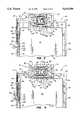
- FIGS. 3, 4 and 5, respectively,are enlarged scale top plan views of portions of the portable computer and expansion base structure in (1) a latched, pre-docking orientation thereof, (2) a docked orientation thereof, and (3) an unlatched, undocked orientation thereof;
- FIG. 6is an enlarged scale detail view of the circled area "6" in FIG. 3:
- FIG. 7is an enlarged scale detail view of the circled area "7" in FIG. 3.
- the present inventionprovides an expansion base structure 10 incorporating therein a specially designed, mechanically advantaged manual docking system 12 and used to releasably and operatively couple or "dock" a portable computer, representatively a notebook computer 14, to desktop computer peripheral devices such as the illustrated monitor 16, keyboard 18 and printer 20.
- a portable computerrepresentatively a notebook computer 14
- desktop computer peripheral devicessuch as the illustrated monitor 16, keyboard 18 and printer 20.
- FIG. 1the expansion base structure 10, the keyboard 18 and the printer 20 are shown resting on a representative horizontal work surface such as a desktop 22.
- the expansion base structure 10includes a generally rectangular bottom side support deck 24 horizontally supported on the desktop area 22, in a slightly elevated relationship therewith, by four cylindrical leg members 26 (see FIG. 2) depending from the corners of the deck 24.
- the support deck 24has opposite front and rear side edges 28,30 and opposite left and right side edges 32,34.
- the expansion base structure 10also has a rectangular housing 36 (shown in phantom in FIGS. 1 and 2) that overlies the support deck 24 and has a rectangular docking opening 38 formed in a front side wall portion 40 of the housing 36, and through which the notebook computer 14 may be removably inserted into the interior of the housing for the purpose of "docking" the inserted computer to the representative desktop computer peripheral devices 16, 18 and 20 as later described herein.
- the housing 36may be omitted, thereby exposing the support deck 24 to view.
- the computer 14is placed on the top side of the deck 24 and slid rearwardly therealong into a docked relationship with the system 12.
- guide rail members 42,44are respectively secured atop left and right side edge portions of the support deck 24 and longitudinally extend in front-to-rear directions.
- the notebook computer 14has a rectangular base housing 46 with a rectangular lid portion 48 pivotally secured to a rear side edge portion of the top side thereof, the lid 48 being illustrated in its closed orientation in FIGS. 1-5.
- Base housing 46has front and rear side walls 50,52 and left and right side walls 54,56 (see FIG. 2), and the lid 48 has front and rear side walls 58,60 and left and right side walls 62,64.
- a horizontally spaced pair of rectangular latching openings 70extend through the rear side wall 60 of the lid 48.
- the manual docking system 12includes a rectangular support block 72 centrally mounted atop a rear side edge portion of the deck 24, and having a front side 74. Projecting forwardly from the front side 74, positioned between a pair of outwardly projecting alignment pins 76, is a female multi-pin electrical connector 78. Connector 78 is electrically coupled to conventional electrical circuitry (not shown) which is disposed within the housing 36 and is operatively coupled to the desktop peripheral devices 16,18,20 (see FIG. 1) respectively via cables 80,82,84 exiting the rear side of the housing 36.
- the computer 14When the computer 14 is operatively docked within the expansion base structure 10, by coupling the connectors 66,78 as subsequently described herein, the computer 14 and the representatively illustrated peripheral devices 16,18,20 are operatively coupled to one another, with the central processing unit of the notebook computer 14 now serving the resulting desktop computing system.
- a rectangular support plate 86is anchored to the top side of the block 72, and a rectangular drive plate 88 having a front end 90 is slidably supported on the top side of the plate 86 for driven forward and rearward movement relative thereto by pins 92 projecting upwardly from the underlying plate 86 and received in corresponding slots 94 in the drive plate 88.
- the drive plate 88has a forwardly-to-rearwardly spaced pair of rounded projections 96 (see FIG. 7).
- projections 96are cammingly received in corresponding arcuate side edge notches 98 in a spaced pair of elongated, parallel latch arm plates 100 slidably resting atop the support plate 86 on opposite sides of the drive plate 88 (see FIGS. 5 and 7 also).
- Latch arms 100are guided for controlled longitudinal and lateral movement along the top side of the support plate 86 by pins 102 depending from the latch arms and slidably received in underlying arcuate slots 104 formed in the support plate 86 as best illustrated in FIG. 7.
- Each of the latch arms 100has an outer end portion 106 that projects forwardly beyond the support block 72, is inwardly insertable into one of the latching openings 70 in the rear side wall 60 of the computer lid 48, and has a rearwardly facing flat catch surface 108 (see FIG. 6) and a sloping cam surface 109.
- the latch arms 100are laterally and resiliently biased toward one another by a pair of coiled tension springs 110, and are restrained against vertical removal from the top side of the support plate 86 by a pair of restraining bar members 112 overlying the arms 100 and secured to the top side of the support plate 86.
- a rotatable lever 114overlies the left latch arm 100 and has a right or inner end pivotally connected at point 116 to the top side of the drive plate 88, a longitudinally intermediate portion pivotally connected at point 118 to a mounting plate 120 secured to the top side of the support block 72 to the left of the support plate 86, and a downwardly offset left or outer end 122.
- Outer lever end 122is pivotally connected to the rear end of an elongated, longitudinally reciprocable drive arm 124 that is positioned outwardly of and parallel to the left guide rail 42.
- the drive arm 124has an inverted U-shaped front end portion 126 that underlies and is restrained against upward movement by a horizontally sloped guide strip member 128 suitably secured to the outer side of the left guide rail 42.
- a generally U-shaped crank member 130has a central portion pivotally connected to one end of a connector member 132, the other end of which is received in and pivotally connected to the front end portion 126 of the reciprocable drive arm 124. As illustrated, one end of the crank member 130 is pivotally connected to the left guide rail at point 134 thereon, while the other end of the crank member 130 is pivotally connected to one end of an elongated rectangularly shaped manual pivot member 136.
- the member 136may be manually pivoted among three positions, namely (1) a pre-docking or "neutral" position (FIGS.
- the pivot member 136is resiliently biased toward its pre-docking orientation (shown in FIGS. 2 and 3) by front and rear coil springs 138 and 140 that overlie the drive arm 124 in a parallel relationship therewith.
- Front spring 138is interconnected between the outer end 122 of the rotatable lever 114 and a fixed point 142 on the left guide rail 42, and the rear spring 140 is interconnected between the guide rail point 142 and the front end 126 of the drive arm 124.
- the notebook computer 14is "docked" to the expansion base structure 10, and thus operatively coupled to the representative desktop peripheral devices 16,18,20 as follows.
- the computer 14is simply inserted, rear side first, inwardly through the housing opening 38 (see FIG. 1) in a manner such that the bottom side of the computer is slid along the top side of the support deck 24, with the opposite sides of the inserted computer also being slidably engaged by the guide rails 42 and 42 to thereby horizontally and vertically align the mateable computer and docking system electrical connectors 66,78.
- the outer ends 106 of the latch arms 100enter the rear side computer lid openings 70 in a manner such that the sloped surfaces 109 of the latch member ends 106 engage peripheral portions of the rear side lid wall 60 and cam the outer latch member ends 106 slightly outwardly away from one another against the resilient tension resistance of the front spring 110.
- the front spring 110causes the front latch arm ends 106 to snap toward one another in a manner causing the rearwardly facing flat surfaces 108 of the front latch arm ends 106 to forwardly overlie the inner surface of the rear lid wall 60 to thereby lock the inserted computer against rearward removal from the housing 36.
- the alignment pins 76enter the corresponding alignment holes 70 in the rear side base housing wall 52, thereby adding to the precision with which the connectors 66,78 are aligned before they are mated as the docking sequence is completed.
- the connectors 66,78are contiguous with one another, but not yet mated, and the front end 90 of the drive plate 88 is spaced a short distance rearwardly of the rear side of the inserted computer 14.
- the pivot member 136is manually rotated rearwardly through an arc of approximately ninety degrees to bring it to its docked orientation.
- This rearward rotation of the pivot member 136via the crank and connector members 130 and 132, rearwardly translates the reciprocable drive arm 124 from its FIG. 3 position to its FIG. 4 position.
- Thisforcibly rotates the lever 114 in a counterclockwise direction about the pivot point 118 (as indicated by the arrow 144 in FIG. 4), thereby rearwardly driving the drive plate 88, with a mechanically advantaged force, away from its FIG. 3 position.
- Such rearward movement of the drive platevia the interaction between the drive plate side projections 96 and the associated rear side surface portions of the latch arm notches 98 (see FIG. 7), rearwardly drives the latch arms 100 to thereby rearwardly pull the computer 14 closer to the support block 72 as indicated by the arrows 146 in FIG. 4.
- the driven rearward movement of the computer 14 within the housing 36forcibly drives the computer connector 66 into operatively coupled engagement with its associated docking system connector 78.
- the actual docking operationis accurately and reliably achieved in the present invention by pulling the computer toward the docking system connector 78, with the pulling force being exerted on a horizontally central portion of the rear side of the computer.
- the pivot member 136is manually rotated forwardly from its FIG. 4 docked position to its FIG. 5 undocked position.
- This manual rotation of the pivot member 136via the crank and connector members 130 and 132, forcibly rotates the lever 114 in a counterclockwise direction as indicated by the arrow 148 in FIG. 5.
- this forwardlydrives the plate 88 away from its FIG. 4 position toward the rear side wall 60 of the computer lid 48 as indicated by the arrow 150 in FIG. 5.
- the side projections 96(see FIG. 7) engage front edge portions of their associated latch arm notches 98 and begin to also drive the latch arms 100 in a forward direction.
- the computer 14is rearwardly inserted into the housing 36 and "clicked" onto the front latch arm ends 106.
- the pivot armis then rearwardly rotated to forcibly dock the computer, and is subsequently rotated in the opposite direction to undock the computer 14.
- the manual docking system just describedeliminates the awkwardness and difficultly of having to manually grasp the docked computer and pull it with sufficient force to decouple the computer and docking system connectors. Additionally, the only manual docking force that needs to be applied is applied to the external pivot member 136 (see FIG. 1), the balance of the manual docking system being protectively disposed within the housing 136.
- the docking system 12 illustrated and described hereinmay be used to exert both mechanically advantaged docking and undocking forces on the representatively illustrated notebook computer 14, if desired, the computer 14 can be easily docked to the expansion base structure 10 without using the pivot member 136. Specifically, after the housing-inserted computer 14 has been "clicked" onto the latch arms 100 the computer user may simply push the inserted computer 14 further back toward the docking system connector 78 to manually effect docking without using the mechanically leveraged docking force resulting from the use of the pivot member 136. Subsequently, the docked computer can be undocked by forwardly rotating the pivot member 136 as previously described.
Landscapes
- Engineering & Computer Science (AREA)
- Theoretical Computer Science (AREA)
- Computer Hardware Design (AREA)
- Human Computer Interaction (AREA)
- Physics & Mathematics (AREA)
- General Engineering & Computer Science (AREA)
- General Physics & Mathematics (AREA)
- Details Of Connecting Devices For Male And Female Coupling (AREA)
Abstract
Description
Claims (20)
Priority Applications (1)
| Application Number | Priority Date | Filing Date | Title |
|---|---|---|---|
| US08/579,290US5619398A (en) | 1995-12-27 | 1995-12-27 | Manual docking apparatus having latch and drive mechanism for a portable computer |
Applications Claiming Priority (1)
| Application Number | Priority Date | Filing Date | Title |
|---|---|---|---|
| US08/579,290US5619398A (en) | 1995-12-27 | 1995-12-27 | Manual docking apparatus having latch and drive mechanism for a portable computer |
Publications (1)
| Publication Number | Publication Date |
|---|---|
| US5619398Atrue US5619398A (en) | 1997-04-08 |
Family
ID=24316309
Family Applications (1)
| Application Number | Title | Priority Date | Filing Date |
|---|---|---|---|
| US08/579,290Expired - LifetimeUS5619398A (en) | 1995-12-27 | 1995-12-27 | Manual docking apparatus having latch and drive mechanism for a portable computer |
Country Status (1)
| Country | Link |
|---|---|
| US (1) | US5619398A (en) |
Cited By (46)
| Publication number | Priority date | Publication date | Assignee | Title |
|---|---|---|---|---|
| US5841994A (en)* | 1996-06-14 | 1998-11-24 | Texas Instruments Incorporated | Portable computer with multiple zoom port interface |
| US5864294A (en)* | 1996-04-01 | 1999-01-26 | Acer, Inc. | Method and device for expanding computer function |
| US5969939A (en)* | 1997-07-08 | 1999-10-19 | Dell Usa, L.P. | Computer with docking station for docking and cooling the computer |
| US5997323A (en)* | 1997-04-15 | 1999-12-07 | Samsung Electronic Co., Ltd. | Device for connecting a portable computer to a docking station |
| US6015308A (en)* | 1999-02-01 | 2000-01-18 | Compal Electronics, Inc. | Docking station for a notebook computer |
| US6034869A (en)* | 1996-12-20 | 2000-03-07 | Compaq Computer Corporation | Locking apparatus for locking a notebook computer on a docking station |
| US6061234A (en)* | 1999-03-15 | 2000-05-09 | Dell U.S.A., L.P. | Secured snap-on cover for a computer system docking station |
| US6069790A (en)* | 1998-01-27 | 2000-05-30 | Dell Usa, L.P. | Portable computer ejection mechanism for docking devices |
| US6072695A (en)* | 1997-10-30 | 2000-06-06 | Hewlett-Packard Company | Horizontal loading docking station with uninterrupted power supply |
| US6093039A (en)* | 1998-08-06 | 2000-07-25 | Mobility Electronics, Inc. | Docking device for a portable computer |
| US6098131A (en)* | 1998-05-04 | 2000-08-01 | Nortel Networks Limited | Network apparatus with removable electronic module |
| US6115246A (en)* | 1996-11-05 | 2000-09-05 | Fujitsu Limited | Function extending apparatus for information processing device |
| US6123557A (en)* | 1998-12-02 | 2000-09-26 | Inventec Corporation | Automatic opening mechanism for docking station connector cover |
| US6135801A (en)* | 1998-04-30 | 2000-10-24 | Hewlett-Packard Company | Computer underside docking method and apparatus |
| US6175491B1 (en)* | 1997-03-10 | 2001-01-16 | Samsung Electronics Co. Ltd. | Locking device and method for peripheral devices |
| US6188572B1 (en) | 1998-10-13 | 2001-02-13 | Dell Usa, L.P. | Movable docking station electrical connector |
| US6231371B1 (en)* | 1999-06-25 | 2001-05-15 | Hewlett-Packard Company | Docking station for multiple devices |
| US6307745B1 (en) | 1998-07-01 | 2001-10-23 | Gateway, Inc. | Computer option bay having secondary access port with automatic sliding door mechanism |
| US6335861B1 (en)* | 1999-03-01 | 2002-01-01 | Cardiocommand, Inc. | Instrument platform using modular components |
| US6480372B1 (en)* | 2000-04-24 | 2002-11-12 | Microsoft Corporation | Computer with a hidden keyboard |
| US20020182896A1 (en)* | 2001-06-01 | 2002-12-05 | Welsh Thomas W. | Latch with bail-type mounting |
| US6510051B2 (en)* | 2000-09-14 | 2003-01-21 | Samsung Electronics Co., Ltd. | Docking apparatus for assembling and disassembling peripheral devices in and from a computer |
| US6560103B1 (en)* | 1998-09-22 | 2003-05-06 | Sanyo Electric Co., Ltd. | Accessory of electronic device |
| US20040075980A1 (en)* | 2002-10-16 | 2004-04-22 | Samsung Electronics Co., Ltd. Of Republic Of Korea | Docking station and notebook computer using the same |
| US20040201601A1 (en)* | 2003-04-09 | 2004-10-14 | Fa-Chih Ke | One-touch release apparatus |
| US20040222647A1 (en)* | 2003-05-07 | 2004-11-11 | Smith Kelly K. | Low profile mechanical assist hood latch |
| US20060023405A1 (en)* | 2004-08-02 | 2006-02-02 | Ming-Yang Lin | Port replicator having display function |
| US20070097617A1 (en)* | 2005-10-31 | 2007-05-03 | Searby Tom J | Electronic device quick connect system |
| US20070097618A1 (en)* | 2005-10-31 | 2007-05-03 | Searby Tom J | Display device quick connect system |
| US20070097619A1 (en)* | 2005-10-31 | 2007-05-03 | David Quijano | Electronic device quick connect system |
| US20070230167A1 (en)* | 2006-04-03 | 2007-10-04 | Welch Allyn, Inc. | Power connections and interface for compact illuminator assembly |
| US20070297130A1 (en)* | 2006-06-23 | 2007-12-27 | Chien-Ming Fan | Locking device for docking station |
| US20080002353A1 (en)* | 2006-06-30 | 2008-01-03 | Carnevali Jeffrey D | Portable device docking station |
| US20080002354A1 (en)* | 2006-06-30 | 2008-01-03 | Carnevali Jeffrey D | Portable device docking station |
| US20080062663A1 (en)* | 2006-09-12 | 2008-03-13 | Qisda Corporation | Display device and electric device |
| CN100397724C (en)* | 2005-01-12 | 2008-06-25 | 英业达股份有限公司 | Lock mechanism for preventing peripheral equipment in multifunctional expansion base from withdrawing |
| WO2007146454A3 (en)* | 2006-06-05 | 2008-07-17 | Vulcan Portals Inc | External module electrical and mechanical attachment mechanism and method |
| US20090213536A1 (en)* | 2008-02-27 | 2009-08-27 | Lewandowski Jason M | Computer docking station for a vehicle |
| US8418219B1 (en) | 2009-08-19 | 2013-04-09 | Communications Test Design, Inc. | Method and apparatus for simultaneously testing multiple set-top boxes |
| US8867202B2 (en) | 2011-08-23 | 2014-10-21 | L&P Property Management Company | Docking station |
| US8929065B2 (en) | 2011-08-23 | 2015-01-06 | L&P Property Management Company | Docking station with ruggedized case |
| US20150062795A1 (en)* | 2013-09-05 | 2015-03-05 | Wistron Corporation | Rotation module with linked plugging and unplugging design |
| US9743547B1 (en)* | 2016-04-19 | 2017-08-22 | Western Digital Technologies, Inc. | Switchable mechanical constraint for electrical connector with compliant mounting |
| CN107453096A (en)* | 2016-05-31 | 2017-12-08 | 南宁富桂精密工业有限公司 | Docking station and the mobile terminal with the docking station |
| US9861011B1 (en) | 2016-06-22 | 2018-01-02 | HGST Netherlands B.V. | Stackable sleds for storing electronic devices |
| US12366902B2 (en)* | 2022-12-19 | 2025-07-22 | Wistron Corp. | Electronic device with plugging and unplugging function |
Citations (7)
| Publication number | Priority date | Publication date | Assignee | Title |
|---|---|---|---|---|
| US5313596A (en)* | 1993-01-05 | 1994-05-17 | Dell Usa Lp | Motorized portable computer/expansion chassis docking system |
| US5323291A (en)* | 1992-10-15 | 1994-06-21 | Apple Computer, Inc. | Portable computer and docking station having an electromechanical docking/undocking mechanism and a plurality of cooperatively interacting failsafe mechanisms |
| US5384686A (en)* | 1990-10-15 | 1995-01-24 | Compaq Computer Corporation | Expansion base and system for portable computers with monitor support |
| US5402310A (en)* | 1993-07-14 | 1995-03-28 | Dell Usa, L.P. | Docking apparatus for a portable data processing unit having undercuts as guide members |
| US5461546A (en)* | 1989-12-15 | 1995-10-24 | Kabushiki Kaisha Toshiba | Connecting apparatus for connecting portable computers |
| US5477415A (en)* | 1993-11-12 | 1995-12-19 | Texas Instruments Incorporated | Automatic computer docking station having a motorized tray, cammed side connectors, motorized side connectors, and locking and unlocking guide pins |
| US5535093A (en)* | 1994-06-20 | 1996-07-09 | International Business Machines Corporation | Portable computer docking device having a first rotatable connector and a second connector |
- 1995
- 1995-12-27USUS08/579,290patent/US5619398A/ennot_activeExpired - Lifetime
Patent Citations (7)
| Publication number | Priority date | Publication date | Assignee | Title |
|---|---|---|---|---|
| US5461546A (en)* | 1989-12-15 | 1995-10-24 | Kabushiki Kaisha Toshiba | Connecting apparatus for connecting portable computers |
| US5384686A (en)* | 1990-10-15 | 1995-01-24 | Compaq Computer Corporation | Expansion base and system for portable computers with monitor support |
| US5323291A (en)* | 1992-10-15 | 1994-06-21 | Apple Computer, Inc. | Portable computer and docking station having an electromechanical docking/undocking mechanism and a plurality of cooperatively interacting failsafe mechanisms |
| US5313596A (en)* | 1993-01-05 | 1994-05-17 | Dell Usa Lp | Motorized portable computer/expansion chassis docking system |
| US5402310A (en)* | 1993-07-14 | 1995-03-28 | Dell Usa, L.P. | Docking apparatus for a portable data processing unit having undercuts as guide members |
| US5477415A (en)* | 1993-11-12 | 1995-12-19 | Texas Instruments Incorporated | Automatic computer docking station having a motorized tray, cammed side connectors, motorized side connectors, and locking and unlocking guide pins |
| US5535093A (en)* | 1994-06-20 | 1996-07-09 | International Business Machines Corporation | Portable computer docking device having a first rotatable connector and a second connector |
Cited By (78)
| Publication number | Priority date | Publication date | Assignee | Title |
|---|---|---|---|---|
| US5864294A (en)* | 1996-04-01 | 1999-01-26 | Acer, Inc. | Method and device for expanding computer function |
| US5841994A (en)* | 1996-06-14 | 1998-11-24 | Texas Instruments Incorporated | Portable computer with multiple zoom port interface |
| US6556436B2 (en) | 1996-11-05 | 2003-04-29 | Fujitsu Limited | Function extending apparatus for information processing device |
| US6115246A (en)* | 1996-11-05 | 2000-09-05 | Fujitsu Limited | Function extending apparatus for information processing device |
| US6233145B1 (en) | 1996-11-05 | 2001-05-15 | Fujitsu Limited | Function extending apparatus for information processing device |
| US6034869A (en)* | 1996-12-20 | 2000-03-07 | Compaq Computer Corporation | Locking apparatus for locking a notebook computer on a docking station |
| US6175491B1 (en)* | 1997-03-10 | 2001-01-16 | Samsung Electronics Co. Ltd. | Locking device and method for peripheral devices |
| US5997323A (en)* | 1997-04-15 | 1999-12-07 | Samsung Electronic Co., Ltd. | Device for connecting a portable computer to a docking station |
| US5969939A (en)* | 1997-07-08 | 1999-10-19 | Dell Usa, L.P. | Computer with docking station for docking and cooling the computer |
| US6072695A (en)* | 1997-10-30 | 2000-06-06 | Hewlett-Packard Company | Horizontal loading docking station with uninterrupted power supply |
| US6069790A (en)* | 1998-01-27 | 2000-05-30 | Dell Usa, L.P. | Portable computer ejection mechanism for docking devices |
| US6264488B1 (en) | 1998-04-30 | 2001-07-24 | Hewlett-Packard Company | Computer underside docking method and apparatus |
| US6220883B1 (en) | 1998-04-30 | 2001-04-24 | Hewlett-Packard Company | Computer underside docking method and apparatus |
| US6135801A (en)* | 1998-04-30 | 2000-10-24 | Hewlett-Packard Company | Computer underside docking method and apparatus |
| US6098131A (en)* | 1998-05-04 | 2000-08-01 | Nortel Networks Limited | Network apparatus with removable electronic module |
| US6307745B1 (en) | 1998-07-01 | 2001-10-23 | Gateway, Inc. | Computer option bay having secondary access port with automatic sliding door mechanism |
| US6093039A (en)* | 1998-08-06 | 2000-07-25 | Mobility Electronics, Inc. | Docking device for a portable computer |
| US6560103B1 (en)* | 1998-09-22 | 2003-05-06 | Sanyo Electric Co., Ltd. | Accessory of electronic device |
| US6188572B1 (en) | 1998-10-13 | 2001-02-13 | Dell Usa, L.P. | Movable docking station electrical connector |
| US6123557A (en)* | 1998-12-02 | 2000-09-26 | Inventec Corporation | Automatic opening mechanism for docking station connector cover |
| US6015308A (en)* | 1999-02-01 | 2000-01-18 | Compal Electronics, Inc. | Docking station for a notebook computer |
| US6335861B1 (en)* | 1999-03-01 | 2002-01-01 | Cardiocommand, Inc. | Instrument platform using modular components |
| US6061234A (en)* | 1999-03-15 | 2000-05-09 | Dell U.S.A., L.P. | Secured snap-on cover for a computer system docking station |
| US6309230B2 (en) | 1999-06-25 | 2001-10-30 | Hewlett-Packard Company | Docking station for multiple devices |
| US6231371B1 (en)* | 1999-06-25 | 2001-05-15 | Hewlett-Packard Company | Docking station for multiple devices |
| US6480372B1 (en)* | 2000-04-24 | 2002-11-12 | Microsoft Corporation | Computer with a hidden keyboard |
| US6510051B2 (en)* | 2000-09-14 | 2003-01-21 | Samsung Electronics Co., Ltd. | Docking apparatus for assembling and disassembling peripheral devices in and from a computer |
| US20020182896A1 (en)* | 2001-06-01 | 2002-12-05 | Welsh Thomas W. | Latch with bail-type mounting |
| WO2002099229A3 (en)* | 2001-06-01 | 2003-10-09 | Southco | Latch with bail-type mounting |
| US6957979B2 (en)* | 2001-06-01 | 2005-10-25 | Southco, Inc. | Latch with bail-type mounting |
| US6898079B2 (en)* | 2002-10-16 | 2005-05-24 | Samsung Electronics Co., Ltd. | Docking station and notebook computer using the same |
| US20040075980A1 (en)* | 2002-10-16 | 2004-04-22 | Samsung Electronics Co., Ltd. Of Republic Of Korea | Docking station and notebook computer using the same |
| US20080316700A1 (en)* | 2003-01-08 | 2008-12-25 | Flextronics Computer Sales & Marketing (L) Ltd. | One-Touch Release Apparatus |
| US7379295B2 (en)* | 2003-04-09 | 2008-05-27 | Arima Computer Corporation | One-touch release apparatus |
| US20040201601A1 (en)* | 2003-04-09 | 2004-10-14 | Fa-Chih Ke | One-touch release apparatus |
| US7325846B2 (en) | 2003-05-07 | 2008-02-05 | Hewlett-Packard Development Company, L.P. | Low profile mechanical assist hood latch |
| US20080061563A1 (en)* | 2003-05-07 | 2008-03-13 | Hewlett-Packard Development Company, L.P. | Low profile mechanical assist hood latch |
| US20040222647A1 (en)* | 2003-05-07 | 2004-11-11 | Smith Kelly K. | Low profile mechanical assist hood latch |
| US7614672B2 (en) | 2003-05-07 | 2009-11-10 | Hewlett-Packard Development Company, L.P. | Low profile mechanical assist hood latch |
| US20060023405A1 (en)* | 2004-08-02 | 2006-02-02 | Ming-Yang Lin | Port replicator having display function |
| CN100397724C (en)* | 2005-01-12 | 2008-06-25 | 英业达股份有限公司 | Lock mechanism for preventing peripheral equipment in multifunctional expansion base from withdrawing |
| US20100014228A1 (en)* | 2005-10-31 | 2010-01-21 | David Quijano | Electronic Device Quick Connect System |
| US7317613B2 (en) | 2005-10-31 | 2008-01-08 | Hewlett-Packard Development Company, L.P. | Electronic device quick connect system |
| US7502226B2 (en) | 2005-10-31 | 2009-03-10 | Hewlett-Packard Development Company, L.P. | Electronic device quick connect system |
| US20070097619A1 (en)* | 2005-10-31 | 2007-05-03 | David Quijano | Electronic device quick connect system |
| US7499272B2 (en) | 2005-10-31 | 2009-03-03 | Hewlett-Packard Development Company, L.P. | Display device quick connect system |
| US20070097618A1 (en)* | 2005-10-31 | 2007-05-03 | Searby Tom J | Display device quick connect system |
| US20070097617A1 (en)* | 2005-10-31 | 2007-05-03 | Searby Tom J | Electronic device quick connect system |
| US20070230167A1 (en)* | 2006-04-03 | 2007-10-04 | Welch Allyn, Inc. | Power connections and interface for compact illuminator assembly |
| US7758203B2 (en) | 2006-04-03 | 2010-07-20 | Welch Allyn, Inc. | Power connections and interface for compact illuminator assembly |
| WO2007146454A3 (en)* | 2006-06-05 | 2008-07-17 | Vulcan Portals Inc | External module electrical and mechanical attachment mechanism and method |
| US7633750B2 (en)* | 2006-06-23 | 2009-12-15 | Hon Hai Precision Industry Co., Ltd. | Locking device for docking station |
| US20070297130A1 (en)* | 2006-06-23 | 2007-12-27 | Chien-Ming Fan | Locking device for docking station |
| US8179672B2 (en)* | 2006-06-30 | 2012-05-15 | National Products, Inc. | Portable device docking station |
| US9036343B2 (en) | 2006-06-30 | 2015-05-19 | National Products, Inc. | Portable device docking station |
| US20080002354A1 (en)* | 2006-06-30 | 2008-01-03 | Carnevali Jeffrey D | Portable device docking station |
| US7508661B2 (en)* | 2006-06-30 | 2009-03-24 | Carnevali Jeffrey D | Portable device docking station |
| US20080002353A1 (en)* | 2006-06-30 | 2008-01-03 | Carnevali Jeffrey D | Portable device docking station |
| US8385058B2 (en)* | 2006-09-12 | 2013-02-26 | Qisda Corporation | Display device and electric device |
| US20080062663A1 (en)* | 2006-09-12 | 2008-03-13 | Qisda Corporation | Display device and electric device |
| US8098488B2 (en) | 2008-02-27 | 2012-01-17 | L&P Property Management Company | Computer docking station for a vehicle |
| US20110128689A1 (en)* | 2008-02-27 | 2011-06-02 | Lewandowski Jason M | Computer docking station for a vehicle |
| USRE43869E1 (en) | 2008-02-27 | 2012-12-25 | L&P Property Management Company | Computer docking station for a vehicle |
| US20090213536A1 (en)* | 2008-02-27 | 2009-08-27 | Lewandowski Jason M | Computer docking station for a vehicle |
| US7978466B2 (en) | 2008-02-27 | 2011-07-12 | L&P Property Management Company | Computer docking station for a vehicle |
| US8418219B1 (en) | 2009-08-19 | 2013-04-09 | Communications Test Design, Inc. | Method and apparatus for simultaneously testing multiple set-top boxes |
| US9310841B2 (en) | 2011-08-23 | 2016-04-12 | L&P Property Management Company | Docking station with ruggedized case |
| US8929065B2 (en) | 2011-08-23 | 2015-01-06 | L&P Property Management Company | Docking station with ruggedized case |
| US9098239B2 (en) | 2011-08-23 | 2015-08-04 | L&P Property Management Company | Docking station with ruggedized case |
| US8867202B2 (en) | 2011-08-23 | 2014-10-21 | L&P Property Management Company | Docking station |
| US20150062795A1 (en)* | 2013-09-05 | 2015-03-05 | Wistron Corporation | Rotation module with linked plugging and unplugging design |
| US9152170B2 (en)* | 2013-09-05 | 2015-10-06 | Wistron Corporation | Rotation module with linked plugging and unplugging design |
| US9743547B1 (en)* | 2016-04-19 | 2017-08-22 | Western Digital Technologies, Inc. | Switchable mechanical constraint for electrical connector with compliant mounting |
| CN107453096A (en)* | 2016-05-31 | 2017-12-08 | 南宁富桂精密工业有限公司 | Docking station and the mobile terminal with the docking station |
| CN107453096B (en)* | 2016-05-31 | 2019-07-23 | 南宁富桂精密工业有限公司 | Docking station and mobile terminal with the docking station |
| US9861011B1 (en) | 2016-06-22 | 2018-01-02 | HGST Netherlands B.V. | Stackable sleds for storing electronic devices |
| US10212854B2 (en) | 2016-06-22 | 2019-02-19 | Western Digital Technologies, Inc. | Stackable sleds for storing electronic devices |
| US12366902B2 (en)* | 2022-12-19 | 2025-07-22 | Wistron Corp. | Electronic device with plugging and unplugging function |
Similar Documents
| Publication | Publication Date | Title |
|---|---|---|
| US5619398A (en) | Manual docking apparatus having latch and drive mechanism for a portable computer | |
| US5818691A (en) | Portable computer docking system with push to engage and push to disengage connection module | |
| US5526493A (en) | Docking detection and suspend circuit for portable computer/expansion chassis docking system | |
| US6208508B1 (en) | Space-saving docking station for vertically supporting an opened notebook computer | |
| US6583985B2 (en) | Elevationally adjustable portable computer docking station | |
| US5477415A (en) | Automatic computer docking station having a motorized tray, cammed side connectors, motorized side connectors, and locking and unlocking guide pins | |
| US6264488B1 (en) | Computer underside docking method and apparatus | |
| US5396400A (en) | Convertible computer apparatus acting as a desk-top computer or a docking station | |
| US5838541A (en) | Computer expansion system including expansion base and monitor support structure | |
| US6231371B1 (en) | Docking station for multiple devices | |
| US5175671A (en) | Expanding apparatus for portable electronic apparatus | |
| US6246575B1 (en) | Modular computer | |
| US5313596A (en) | Motorized portable computer/expansion chassis docking system | |
| US7298613B2 (en) | Portable computer docking station | |
| US20070076363A1 (en) | Notebook computer with detachable display and support stand for detachable display | |
| US6034869A (en) | Locking apparatus for locking a notebook computer on a docking station | |
| US8821173B2 (en) | Docking station having preload and connector isolator system | |
| US6560101B1 (en) | Alignment mechanism for a computer system having a portable computer and a docking station | |
| US6424524B2 (en) | Wedge-shaped port replicator for portable computer | |
| US6280212B1 (en) | Portable computer docking station with movable docking connector | |
| US7038908B2 (en) | Docking-type function-providing apparatus and portable device | |
| US5751546A (en) | Cradle assembly for portable computing devices and method | |
| US6898080B2 (en) | Portable computer docking station with movable electrical interface | |
| US6533599B1 (en) | Self-aligning information processing device docking apparatus and method of use therefor | |
| JP2000029571A (en) | Computer docking device |
Legal Events
| Date | Code | Title | Description |
|---|---|---|---|
| STCF | Information on status: patent grant | Free format text:PATENTED CASE | |
| FEPP | Fee payment procedure | Free format text:PAYOR NUMBER ASSIGNED (ORIGINAL EVENT CODE: ASPN); ENTITY STATUS OF PATENT OWNER: LARGE ENTITY | |
| FPAY | Fee payment | Year of fee payment:4 | |
| AS | Assignment | Owner name:COMPAQ INFORMATION TECHNOLOGIES GROUP, L.P., TEXAS Free format text:ASSIGNMENT OF ASSIGNORS INTEREST;ASSIGNOR:COMPAQ COMPUTER CORPORATION;REEL/FRAME:012418/0222 Effective date:20010620 | |
| AS | Assignment | Owner name:HEWLETT-PACKARD DEVELOPMENT COMPANY, L.P., TEXAS Free format text:CHANGE OF NAME;ASSIGNOR:COMPAQ INFORMATION TECHNOLOGIES GROUP, LP;REEL/FRAME:015000/0305 Effective date:20021001 | |
| FPAY | Fee payment | Year of fee payment:8 | |
| FPAY | Fee payment | Year of fee payment:12 | |
| FEPP | Fee payment procedure | Free format text:PAYER NUMBER DE-ASSIGNED (ORIGINAL EVENT CODE: RMPN); ENTITY STATUS OF PATENT OWNER: LARGE ENTITY Free format text:PAYOR NUMBER ASSIGNED (ORIGINAL EVENT CODE: ASPN); ENTITY STATUS OF PATENT OWNER: LARGE ENTITY |