US5619321A - Method of and device for measuring the Kerr non-linearity coefficient in a single mode optical fiber - Google Patents
Method of and device for measuring the Kerr non-linearity coefficient in a single mode optical fiberDownload PDFInfo
- Publication number
- US5619321A US5619321AUS08/608,481US60848196AUS5619321AUS 5619321 AUS5619321 AUS 5619321AUS 60848196 AUS60848196 AUS 60848196AUS 5619321 AUS5619321 AUS 5619321A
- Authority
- US
- United States
- Prior art keywords
- fiber
- optical fiber
- pulses
- power
- peak power
- Prior art date
- Legal status (The legal status is an assumption and is not a legal conclusion. Google has not performed a legal analysis and makes no representation as to the accuracy of the status listed.)
- Expired - Fee Related
Links
- 238000000034methodMethods0.000titleclaimsabstractdescription15
- 239000013307optical fiberSubstances0.000titleclaimsdescription15
- 239000000835fiberSubstances0.000claimsabstractdescription47
- 239000006185dispersionSubstances0.000claimsabstractdescription13
- 238000001228spectrumMethods0.000claimsabstractdescription13
- 238000005259measurementMethods0.000claimsabstractdescription12
- 230000002547anomalous effectEffects0.000claimsabstractdescription6
- 230000003287optical effectEffects0.000claimsdescription24
- 230000010287polarizationEffects0.000claimsdescription6
- 238000012545processingMethods0.000claimsdescription5
- 230000000694effectsEffects0.000abstractdescription10
- 230000009021linear effectEffects0.000description8
- 230000005855radiationEffects0.000description4
- 230000010363phase shiftEffects0.000description3
- 230000003321amplificationEffects0.000description2
- 238000004891communicationMethods0.000description2
- 239000000463materialSubstances0.000description2
- 230000009022nonlinear effectEffects0.000description2
- 238000003199nucleic acid amplification methodMethods0.000description2
- 230000002269spontaneous effectEffects0.000description2
- 230000005374Kerr effectEffects0.000description1
- 230000015556catabolic processEffects0.000description1
- 238000012512characterization methodMethods0.000description1
- 238000006731degradation reactionMethods0.000description1
- 238000010586diagramMethods0.000description1
- 238000012986modificationMethods0.000description1
- 230000004048modificationEffects0.000description1
- 230000003595spectral effectEffects0.000description1
- 238000012360testing methodMethods0.000description1
Images

Classifications
- G—PHYSICS
- G01—MEASURING; TESTING
- G01M—TESTING STATIC OR DYNAMIC BALANCE OF MACHINES OR STRUCTURES; TESTING OF STRUCTURES OR APPARATUS, NOT OTHERWISE PROVIDED FOR
- G01M11/00—Testing of optical apparatus; Testing structures by optical methods not otherwise provided for
- G01M11/30—Testing of optical devices, constituted by fibre optics or optical waveguides
- G01M11/33—Testing of optical devices, constituted by fibre optics or optical waveguides with a light emitter being disposed at one fibre or waveguide end-face, and a light receiver at the other end-face
- G01M11/332—Testing of optical devices, constituted by fibre optics or optical waveguides with a light emitter being disposed at one fibre or waveguide end-face, and a light receiver at the other end-face using discrete input signals
Definitions
- the invention described hereinrelates to the characterization of optical fibers. More particularly an object of the invention is to provide a method of and a device for measuring the non-linearity coefficient in a single mode optical fiber.
- Kerr optical effectacts on the refractive index making it depend on optical intensity I according to the formula:
- n(I)is the refractive index as a function of the intensity (and therefore of the power) of the radiation sent into the fiber
- n 0is the linear refractive index (constant)
- n 2is the so-called non-linear coefficient of the refractive index (also known simply as the non-linear refractive index).
- non-linear effectsare generally characterized in terms of the so-called Kerr non-linearity coefficient ⁇ , which takes into account also light confinement inside the fiber and therefore yields information that is more useful, from the operational point of view, than that provided by the nonlinear refractive index n 2 , which is a parameter depending solely on the material.
- Coefficient ⁇is given by relation
- ⁇is the wavelength and A eff is the effective area of the fiber core, which is a parameter providing a measure of the optical confinement of light inside the fiber. From the value of ⁇ it is therefore possible to obtain the value of n 2 , once A eff is known.
- the mathematical expression of parameter A effis well known to those skilled in the art and therefore it is not necessary to report it here.
- the pulses usedare generally very short, to obtain the peak powers required, and the product of pulse width ⁇ and spectral line width ⁇ must be such as to make the pulse transform limited.
- the inventionis based on a typical manifestation of the optical Kerr effect, the so-called "modulation instability".
- This phenomenonoccurs when a continuous, high-power optical signal is sent through a fiber under anomalous dispersion conditions (i.e. when the wavelength ⁇ of the signal exceeds the zero dispersion wavelength ⁇ 0 of the fiber).
- the continuous wavebecomes unstable (hence the name of the effect) and two gain side bands are generated in the optical spectrum; these side bands are symmetrical with respect to the carrier and their maxima are separated from the carrier by a frequency ⁇ M .
- signal power Pcan be considered constant (i.e. if attenuation introduced by the fiber can be neglected)
- maximum gain G in these bandsis linked through ⁇ only to power P and it is given by
- a train of rectangular pulsesis sent into the fiber, the pulses having such a wavelength that the fiber functions under anomalous dispersion conditions, such a peak power as to cause modulation instability in the fiber and such a ratio between duration and repetition period that the average power is lower than the threshold at which the stimulated Brillouin effect takes place.
- the maximum value of the modulation instability gainis measured, within the spectrum of the pulses exiting the fiber, for a number of values of the pulse peak power.
- the non-linearity coefficient ⁇is obtained from the maximum measured values of modulation instability gain by minimizing the error, in the range of power values used for the measurement, with respect to a theoretical curve expressing such maximum gain as a function of the peak power.
- FIG. 1is a schematic diagram of the device which performs the method
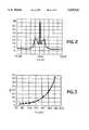
- FIG. 2depicts a typical spectrum of the signal exiting the fiber
- FIG. 3is a graph which compares experimental data with the theoretical curve of the modulation instability gain.
- a sourcefor instance a distributed feedback laser, generates a continuous signal which is sent to an amplitude modulator 2, which transforms the continuous signal into a train of rectangular pulses with duration t and repetition period T.
- the train of rectangular pulsesis amplified in an optical amplification stage 3, which brings the pulses to such a power level as to cause modulation instability in the fiber 5 under test.
- the amplified signalis sent into fiber 5 through a variable attenuator 4, which allows selection of different values for the average power.
- a signal with an optical spectrum like that depicted in FIG. 2is obtained.
- the signal leaving fiber 5is collected by an optical spectrum analyzer 6, or by another instrument capable of determining maximum gain G in correspondence with the two side bands as peak power P (given by the product of the average power by the inverse T/t of the duty cycle) varies.
- a processing system 7, associated with analyzer 6 and driving modulator 2obtains the value of ⁇ by minimizing, in the range of variation of P, the differences between the experimental values and the theoretical curve
- ⁇is a coefficient of proportionality, which is linked to pulse duty cycle and whose value takes into account the polarisation state of the signals
- ais the coefficient defined above
- L effis the effective length of fiber 5, also defined above.
- Relation (4)which applies in the case of a sequence of rectangular pulses, can be obtained from relation (3), which applies for a continuous signal, through simple physical considerations, by taking into account that the spectrum of the light entering the fiber comprises the monochromatic signal emitted by laser 1 and amplified by amplifier 3 and the amplified spontaneous emission of the amplifier, and that the noise of the amplified spontaneous emission is actually amplified as an effect of modulation instability only when it superimposed in time to a pulse (i.e. for time t during period T) and it has the same polarization state as the pulse.
- G(P)is an average value of the maximum modulation instability gain, since the radiometers present in spectrum analyzer 6 measure average power.
- fiber 5For the modulation instability phenomenon to take place, fiber 5 must operate under anomalous dispersion conditions, i.e. wavelength ⁇ , of the radiation sent into the fiber must be higher than zero dispersion wavelength ⁇ 0 . This can easily be obtained with sources emitting radiations with wavelengths within the third window (about 1.55 ⁇ m), as required by erbium-doped fiber amplifiers, which are the most commonly used amplifiers.
- period Tmust be much smaller than the relaxation time of optical amplifiers 3, to avoid pulse distortions due to the gain dynamics of the amplifiers. If this condition for T is met, the amplifiers are only responsive to the average power of the signal. The high peak powers needed to observe non linear phenomena are therefore obtained by reducing ratio t/T. Suitable values are a few hundreds of nanoseconds for T and a few tens of nanoseconds for t. Wide tolerances are possible both for t and T.
- FIG. 2depicts the spectrum of a pulse at the output of the fiber for a peak power of 180 mW. The measure refers only to the polarization parallel to the signal.
- FIG. 3shows a certain number of measured values of G in the conditions specified above, and the theoretical curve. The measurement accuracy allowed by the invention can clearly be seen.
- a fiber of the length given above, together with modulation of the source,allows the stimulated Brillouin effect to be suppressed.
Landscapes
- Physics & Mathematics (AREA)
- Optics & Photonics (AREA)
- Chemical & Material Sciences (AREA)
- Analytical Chemistry (AREA)
- General Physics & Mathematics (AREA)
- Testing Of Optical Devices Or Fibers (AREA)
- Spectrometry And Color Measurement (AREA)
- Investigating Or Analysing Materials By Optical Means (AREA)
- Measuring Magnetic Variables (AREA)
- Photometry And Measurement Of Optical Pulse Characteristics (AREA)
Abstract
Description
n(I)=n.sub.0 =n.sub.2 ·I (1)
γ=(2π/λ)·(n.sub.2 /A.sub.eff) (2)
G=e.sup.2γPL ( 3)
G(P)=1+η(e.sup.2γaPL.sbsp.eff -1) (4)
Claims (5)
Applications Claiming Priority (2)
| Application Number | Priority Date | Filing Date | Title |
|---|---|---|---|
| IT95A000290 | 1995-04-13 | ||
| IT95TO000290AIT1280866B1 (en) | 1995-04-13 | 1995-04-13 | PROCEDURE AND EQUIPMENT FOR MEASURING THE KERR NON-LINEARITY COEFFICIENT IN A SINGLE-MODE OPTICAL FIBER. |
Publications (1)
| Publication Number | Publication Date |
|---|---|
| US5619321Atrue US5619321A (en) | 1997-04-08 |
Family
ID=11413494
Family Applications (1)
| Application Number | Title | Priority Date | Filing Date |
|---|---|---|---|
| US08/608,481Expired - Fee RelatedUS5619321A (en) | 1995-04-13 | 1996-02-28 | Method of and device for measuring the Kerr non-linearity coefficient in a single mode optical fiber |
Country Status (6)
| Country | Link |
|---|---|
| US (1) | US5619321A (en) |
| EP (1) | EP0737852B1 (en) |
| JP (1) | JP2739685B2 (en) |
| CA (1) | CA2174028C (en) |
| DE (2) | DE69613269T2 (en) |
| IT (1) | IT1280866B1 (en) |
Cited By (9)
| Publication number | Priority date | Publication date | Assignee | Title |
|---|---|---|---|---|
| US5880824A (en)* | 1996-09-13 | 1999-03-09 | Ando Electric Co., Ltd. | Optical fiber strain measuring apparatus |
| US6154584A (en)* | 1999-02-03 | 2000-11-28 | Lan-Hopper Systems, Inc. | Optical analyzer with variable attenuators at inputs and outputs |
| US20090117932A1 (en)* | 2006-03-15 | 2009-05-07 | Nec Corporation | Apparatus for controlling signal-transmission power, mobile station, method of controlling signal-transmission power, and program |
| US20130183046A1 (en)* | 2012-01-13 | 2013-07-18 | Esi-Pyrophotonics Lasers, Inc. | Methods and systems for a pulsed laser source emitting a predetermined output pulse profile |
| US20170248491A1 (en)* | 2016-02-26 | 2017-08-31 | Christophe Dorrer | Diagnostic for resolution-enhanced temporal measurement of short optical pulses |
| US10659153B2 (en) | 2017-01-06 | 2020-05-19 | Huawei Technologies Co., Ltd. | Method for measuring dispersion coefficient of optical fiber and network device |
| US20210273407A1 (en)* | 2018-09-21 | 2021-09-02 | Hamamatsu Photonics K.K. | Laser device, and laser waveform control method |
| CN114252246A (en)* | 2021-12-31 | 2022-03-29 | 湖南大科激光有限公司 | Optical fiber testing method and system |
| US11652547B2 (en) | 2021-09-24 | 2023-05-16 | Huawei Technologies Co., Ltd. | Method and systems to identify types of fibers in an optical network |
Family Cites Families (6)
| Publication number | Priority date | Publication date | Assignee | Title |
|---|---|---|---|---|
| SU1126084A1 (en)* | 1980-04-28 | 1985-05-30 | Белорусский Ордена Трудового Красного Знамени Политехнический Институт | Magnetographic flaw detector |
| SU1105830A1 (en)* | 1983-03-11 | 1984-07-30 | Научно-Исследовательский Институт Автоматики И Электромеханики При Томском Институте Автоматизированных Систем Управления И Радиоэлектроники | Device for measuring non-linearity of ramp voltage |
| GB9019011D0 (en)* | 1990-08-31 | 1990-10-17 | British Telecomm | Methods and apparatus for processing an optical pulse |
| WO1992016037A1 (en)* | 1991-03-01 | 1992-09-17 | Australian And Overseas Telecommunications Corporation Limited | Modelocked lasers |
| JPH06331944A (en)* | 1993-05-26 | 1994-12-02 | Nec Corp | Nonlinear optical element |
| EP0697775B1 (en)* | 1994-08-15 | 2005-08-10 | Nippon Telegraph And Telephone Corporation | Multiple-channel all-optical TDM-WDM converter and multiple-channel all-optical TDM demultiplexer |
- 1995
- 1995-04-13ITIT95TO000290Apatent/IT1280866B1/enactiveIP Right Grant
- 1996
- 1996-02-28USUS08/608,481patent/US5619321A/ennot_activeExpired - Fee Related
- 1996-04-12DEDE69613269Tpatent/DE69613269T2/ennot_activeExpired - Fee Related
- 1996-04-12DEDE0737852Tpatent/DE737852T1/enactivePending
- 1996-04-12EPEP96105776Apatent/EP0737852B1/ennot_activeExpired - Lifetime
- 1996-04-12CACA002174028Apatent/CA2174028C/ennot_activeExpired - Fee Related
- 1996-04-15JPJP8115225Apatent/JP2739685B2/ennot_activeExpired - Fee Related
Non-Patent Citations (6)
| Title |
|---|
| Fiber Nonlinearity, Tkach, AT&T Bell Lab., Nonlinear Index Measurement by SPM OFC 95 Technical Digest.* |
| Fiber Nonlinearity, Tkach, AT&T Bell Lab., Nonlinear-Index Measurement by SPM OFC '95 Technical Digest. |
| Measurement of the Nonlinear Index of Silica Core and Dispersion Shifted Fibers K. S. Kim et al and Reed et al, 15, Feb. 94/vol. 19, No. 4/Optics Letters.* |
| Measurement of the Nonlinear Index of Silica-Core and Dispersion Shifted-Fibers K. S. Kim et al and Reed et al, 15, Feb. 94/vol. 19, No. 4/Optics Letters. |
| Nonlinear Coefficient Measurements for Dispersion Shifted Fibers Using Self Phase Y. Namihira et al, Electronics Letters, 7 Jul. 1994, vol. 30, No. 14.* |
| Nonlinear Coefficient Measurements for Dispersion Shifted Fibers Using Self-Phase Y. Namihira et al, Electronics Letters, 7 Jul. 1994, vol. 30, No. 14. |
Cited By (13)
| Publication number | Priority date | Publication date | Assignee | Title |
|---|---|---|---|---|
| US5880824A (en)* | 1996-09-13 | 1999-03-09 | Ando Electric Co., Ltd. | Optical fiber strain measuring apparatus |
| US6154584A (en)* | 1999-02-03 | 2000-11-28 | Lan-Hopper Systems, Inc. | Optical analyzer with variable attenuators at inputs and outputs |
| US8554263B2 (en) | 2006-03-15 | 2013-10-08 | Nec Corporation | Apparatus for controlling signal-transmission power, mobile station, method of controlling signal-transmission power, and program |
| US20090117932A1 (en)* | 2006-03-15 | 2009-05-07 | Nec Corporation | Apparatus for controlling signal-transmission power, mobile station, method of controlling signal-transmission power, and program |
| US8380238B2 (en)* | 2006-03-15 | 2013-02-19 | Nec Corporation | Apparatus for controlling signal-transmission power, mobile station, method of controlling signal-transmission power, and program |
| US8958705B2 (en)* | 2012-01-13 | 2015-02-17 | Esi-Pyrophotonics Lasers Inc. | Methods and systems for a pulsed laser source emitting a predetermined output pulse profile |
| US20130183046A1 (en)* | 2012-01-13 | 2013-07-18 | Esi-Pyrophotonics Lasers, Inc. | Methods and systems for a pulsed laser source emitting a predetermined output pulse profile |
| US20170248491A1 (en)* | 2016-02-26 | 2017-08-31 | Christophe Dorrer | Diagnostic for resolution-enhanced temporal measurement of short optical pulses |
| US10659153B2 (en) | 2017-01-06 | 2020-05-19 | Huawei Technologies Co., Ltd. | Method for measuring dispersion coefficient of optical fiber and network device |
| US20210273407A1 (en)* | 2018-09-21 | 2021-09-02 | Hamamatsu Photonics K.K. | Laser device, and laser waveform control method |
| US12362539B2 (en)* | 2018-09-21 | 2025-07-15 | Hamamatsu Photonics K.K. | Laser device, and laser waveform control method |
| US11652547B2 (en) | 2021-09-24 | 2023-05-16 | Huawei Technologies Co., Ltd. | Method and systems to identify types of fibers in an optical network |
| CN114252246A (en)* | 2021-12-31 | 2022-03-29 | 湖南大科激光有限公司 | Optical fiber testing method and system |
Also Published As
| Publication number | Publication date |
|---|---|
| DE69613269D1 (en) | 2001-07-19 |
| JPH08285729A (en) | 1996-11-01 |
| EP0737852A3 (en) | 1998-07-08 |
| ITTO950290A0 (en) | 1995-04-13 |
| CA2174028A1 (en) | 1996-10-14 |
| DE69613269T2 (en) | 2001-11-15 |
| EP0737852B1 (en) | 2001-06-13 |
| EP0737852A2 (en) | 1996-10-16 |
| JP2739685B2 (en) | 1998-04-15 |
| IT1280866B1 (en) | 1998-02-11 |
| CA2174028C (en) | 2001-11-20 |
| DE737852T1 (en) | 1999-02-25 |
| ITTO950290A1 (en) | 1996-10-13 |
Similar Documents
| Publication | Publication Date | Title |
|---|---|---|
| US4997277A (en) | Optical fiber evaluation method and system | |
| JP3376251B2 (en) | Method for mapping chromatic dispersion in optical fiber span | |
| US5724126A (en) | Method for measuring distribution of zero dispersion wavelengths in an optical fiber and apparatus therefor | |
| CA2247293A1 (en) | Distributed sensing apparatus | |
| US6016213A (en) | Method and apparatus for optical amplifier gain and noise figure measurement | |
| US5619321A (en) | Method of and device for measuring the Kerr non-linearity coefficient in a single mode optical fiber | |
| US6459479B1 (en) | Optical detection of a fiber span with high polarization-mode dispersion in a fiber system | |
| US6081323A (en) | Measurement of Raman gain spectrum in optical fiber | |
| US6067149A (en) | Dispersion-map measurements of optical fibers | |
| US5661554A (en) | Method of and device for measuring the nonlinear refractive index in a single mode optical fibre | |
| Set et al. | Rapid amplitude and group-delay measurement system based on intra-cavity-modulated swept-lasers | |
| US12388527B2 (en) | Brillouin gain spectrum distribution measurement method and equipment | |
| US6417926B1 (en) | Wavelength measuring system | |
| US6959150B2 (en) | Optical method and system for measuring in-band crosstalk in Raman amplifiers | |
| Simova et al. | Characterization of chromatic dispersion and polarization sensitivity in fiber gratings | |
| JP3291158B2 (en) | Method and apparatus for measuring nonlinear refractive index of optical fiber | |
| Brown et al. | Combined Raman and Brillouin scattering sensor for simultaneous high-resolution measurement of temperature and strain | |
| CN114924280B (en) | A frequency self-scanning single-frequency continuous wave laser ranging system | |
| KR20000051885A (en) | Dispersion value measurement system of optical fiber | |
| JP2000081374A (en) | Method and device for measuring wavelength dispersion | |
| JP3317656B2 (en) | Optical component chromatic dispersion measuring device | |
| Philen | Measurement of the Non-Linear Index of Refraction, N2 | |
| US7298465B2 (en) | Measurement and characterization of nonlinear phase shifts | |
| JPH0331736A (en) | Method and instrument for measuring curvature distribution of optical fiber | |
| CN120545780A (en) | High-speed swept-frequency light source for Rayleigh frequency demodulation in fiber-optic distributed acoustic sensing |
Legal Events
| Date | Code | Title | Description |
|---|---|---|---|
| AS | Assignment | Owner name:CSELT-CENTRO STUDI E LABORATORI TELECOMUNICAZIONI Free format text:ASSIGNMENT OF ASSIGNORS INTEREST;ASSIGNORS:ARTIGLIA, MASSIMO;CIARAMELLA, ERNESTO;SORDO, BRUNO;REEL/FRAME:007893/0398 Effective date:19960220 | |
| AS | Assignment | Owner name:OTC - OPTICAL TECHNOLOGIES CENTER S.R.L., ITALY Free format text:ASSIGNMENT OF ASSIGNORS INTEREST;ASSIGNOR:CSELT - CENTRO STUDI E LABORATORI TELECOMUNICAZIONI S.P.A.;REEL/FRAME:010785/0391 Effective date:20000406 | |
| FPAY | Fee payment | Year of fee payment:4 | |
| AS | Assignment | Owner name:AGILENT TECHNOLOGIES, INC., CALIFORNIA Free format text:ASSIGNMENT OF ASSIGNORS INTEREST;ASSIGNOR:OTC - OPTICAL TECHNOLOGIES CENTER S.R.L.;REEL/FRAME:011449/0294 Effective date:20010111 | |
| FPAY | Fee payment | Year of fee payment:8 | |
| AS | Assignment | Owner name:AVAGO TECHNOLOGIES GENERAL IP PTE. LTD., SINGAPORE Free format text:ASSIGNMENT OF ASSIGNORS INTEREST;ASSIGNOR:AGILENT TECHNOLOGIES, INC.;REEL/FRAME:017207/0020 Effective date:20051201 | |
| REMI | Maintenance fee reminder mailed | ||
| LAPS | Lapse for failure to pay maintenance fees | ||
| LAPS | Lapse for failure to pay maintenance fees | Free format text:PATENT EXPIRED FOR FAILURE TO PAY MAINTENANCE FEES (ORIGINAL EVENT CODE: EXP.); ENTITY STATUS OF PATENT OWNER: LARGE ENTITY | |
| STCH | Information on status: patent discontinuation | Free format text:PATENT EXPIRED DUE TO NONPAYMENT OF MAINTENANCE FEES UNDER 37 CFR 1.362 | |
| FP | Lapsed due to failure to pay maintenance fee | Effective date:20090408 | |
| AS | Assignment | Owner name:AVAGO TECHNOLOGIES GENERAL IP (SINGAPORE) PTE. LTD Free format text:CORRECTIVE ASSIGNMENT TO CORRECT THE NAME OF THE ASSIGNEE PREVIOUSLY RECORDED ON REEL 017207 FRAME 0020. ASSIGNOR(S) HEREBY CONFIRMS THE ASSIGNMENT;ASSIGNOR:AGILENT TECHNOLOGIES, INC.;REEL/FRAME:038633/0001 Effective date:20051201 |