US5619193A - Surface material and condition sensing system - Google Patents
Surface material and condition sensing systemDownload PDFInfo
- Publication number
- US5619193A US5619193AUS08/660,232US66023296AUS5619193AUS 5619193 AUS5619193 AUS 5619193AUS 66023296 AUS66023296 AUS 66023296AUS 5619193 AUS5619193 AUS 5619193A
- Authority
- US
- United States
- Prior art keywords
- chamber
- vehicle
- signal
- platform
- processor
- Prior art date
- Legal status (The legal status is an assumption and is not a legal conclusion. Google has not performed a legal analysis and makes no representation as to the accuracy of the status listed.)
- Expired - Lifetime
Links
Images


Classifications
- B—PERFORMING OPERATIONS; TRANSPORTING
- B60—VEHICLES IN GENERAL
- B60R—VEHICLES, VEHICLE FITTINGS, OR VEHICLE PARTS, NOT OTHERWISE PROVIDED FOR
- B60R16/00—Electric or fluid circuits specially adapted for vehicles and not otherwise provided for; Arrangement of elements of electric or fluid circuits specially adapted for vehicles and not otherwise provided for
- B60R16/02—Electric or fluid circuits specially adapted for vehicles and not otherwise provided for; Arrangement of elements of electric or fluid circuits specially adapted for vehicles and not otherwise provided for electric constitutive elements
- B60R16/023—Electric or fluid circuits specially adapted for vehicles and not otherwise provided for; Arrangement of elements of electric or fluid circuits specially adapted for vehicles and not otherwise provided for electric constitutive elements for transmission of signals between vehicle parts or subsystems
- B60R16/0237—Electric or fluid circuits specially adapted for vehicles and not otherwise provided for; Arrangement of elements of electric or fluid circuits specially adapted for vehicles and not otherwise provided for electric constitutive elements for transmission of signals between vehicle parts or subsystems circuits concerning the atmospheric environment
- B—PERFORMING OPERATIONS; TRANSPORTING
- B60—VEHICLES IN GENERAL
- B60T—VEHICLE BRAKE CONTROL SYSTEMS OR PARTS THEREOF; BRAKE CONTROL SYSTEMS OR PARTS THEREOF, IN GENERAL; ARRANGEMENT OF BRAKING ELEMENTS ON VEHICLES IN GENERAL; PORTABLE DEVICES FOR PREVENTING UNWANTED MOVEMENT OF VEHICLES; VEHICLE MODIFICATIONS TO FACILITATE COOLING OF BRAKES
- B60T8/00—Arrangements for adjusting wheel-braking force to meet varying vehicular or ground-surface conditions, e.g. limiting or varying distribution of braking force
- B60T8/17—Using electrical or electronic regulation means to control braking
- B60T8/172—Determining control parameters used in the regulation, e.g. by calculations involving measured or detected parameters
- G—PHYSICS
- G01—MEASURING; TESTING
- G01N—INVESTIGATING OR ANALYSING MATERIALS BY DETERMINING THEIR CHEMICAL OR PHYSICAL PROPERTIES
- G01N1/00—Sampling; Preparing specimens for investigation
- G01N1/02—Devices for withdrawing samples
- E—FIXED CONSTRUCTIONS
- E01—CONSTRUCTION OF ROADS, RAILWAYS, OR BRIDGES
- E01C—CONSTRUCTION OF, OR SURFACES FOR, ROADS, SPORTS GROUNDS, OR THE LIKE; MACHINES OR AUXILIARY TOOLS FOR CONSTRUCTION OR REPAIR
- E01C19/00—Machines, tools or auxiliary devices for preparing or distributing paving materials, for working the placed materials, or for forming, consolidating, or finishing the paving
- E01C19/12—Machines, tools or auxiliary devices for preparing or distributing paving materials, for working the placed materials, or for forming, consolidating, or finishing the paving for distributing granular or liquid materials
- E01C19/20—Apparatus for distributing, e.g. spreading, granular or pulverulent materials, e.g. sand, gravel, salt, dry binders
- E01C2019/2055—Details not otherwise provided for
- E01C2019/207—Feeding the distribution means
- E01C2019/208—Feeding the distribution means with longitudinal auger
- G—PHYSICS
- G01—MEASURING; TESTING
- G01N—INVESTIGATING OR ANALYSING MATERIALS BY DETERMINING THEIR CHEMICAL OR PHYSICAL PROPERTIES
- G01N1/00—Sampling; Preparing specimens for investigation
- G01N1/02—Devices for withdrawing samples
- G01N2001/028—Sampling from a surface, swabbing, vaporising
Definitions
- This inventiongenerally relates to vehicle mounted sensor systems and more particularly to a system for determining characteristics of surface material related to adverse driving conditions from a vehicle.
- the system in accordance with the present inventionaddresses the above described needs. It is thus an object of the present invention to provide a unique multipurpose system which includes a multipurpose sensor mounting platform accommodating a variety of sensors that enables the temporary use of materials such as rainwater and road conditioning materials actually encountered on a road surface to determine the condition of the road surface. It is another object of the invention to provide a system for detecting the actual materials on a roadway. It is another object of the invention to provide a system for determining a characteristic such as friction coefficients or the actual freezing temperature of a material on a road surface regardless of the makeup of the material. It is a still further object of the present invention to provide a reliable display of information to the vehicle operator of actual and pending conditions of the road surface. It is a still further object of the invention to provide an apparatus for sensing actual road conditions that can function automatically or manually.
- One embodiment of the apparatus for sensing surface material condition in accordance with the present inventioncomprises a collection means for receiving material discharged, for example, from a vehicle wheel in contact with a roadway surface, at least one sensing means coupled to the collection means for detecting a characteristic of the received material such as friction coefficients, temperature, conductivity, and chemical concentrations and producing a corresponding signal, processing means for converting the corresponding signal, and display means connected to the processing means for providing an indication of surface conditions based on the material characteristics.
- the collection meansmay include a conventional mud flap located immediately behind a vehicle wheel so that a portion of any surface material that is picked up by the vehicle wheel and thrown against the flap may be collected.
- An alternative collection meansis a scoop located in proximity of the wheel or adjacent the road surface to collect deposited surface material.
- Another embodiment of the inventiondoes not require a collection means, but instead, remotely senses directly the surface material characteristics such as temperature, conductivity, friction coefficients or chemical concentrations.
- This embodimentutilizes a sensor located on the undercarriage of the vehicle at a preferably fixed distance from the road surface which senses the surface temperature and at least one other unique surface material characteristic so that the specific material or materials can be identified, the composition determined, and freezing temperatures determined.
- Another embodiment of the apparatushas a sensor mud flap which includes a channel leading into a detection chamber where liquid runoff from the wheel flap is periodically collected and then frozen.
- the freeze pointis sensed along with the temperature of the collected material. This information is displayed to the operator of the vehicle. Once the freeze point is determined, the frozen material is thawed and discharged from the chamber so that a new sample may be collected and analyzed.
- Another embodiment of the inventionincludes an endless belt of liquid absorbing material mounted to the flap.
- the endless beltcollects and absorbs liquid collected by the flap, transports it to a collector which extracts the liquid from the belt and directs it to the sensor means which also can be a detection chamber where the chamber contents is frozen in order to sense the freeze point.
- the sensing meansmay be a single sensor or a combination of several sensors to detect particular parameters of interest.
- the road conditionsare primarily affected by changes in temperature and material concentrations. Therefore the sensing means may include resistance temperature detectors, thermocouple, infrared temperature sensors, conductivity detectors, close proximity electromagnetic radiation (EMR) transmitters and detectors or transceivers, friction measurement devices, and other material analysis systems such as a spectrographic analysis system such as a mass spectrometer.
- EMRelectromagnetic radiation
- the mass spectrometer or other material analysis devicewould preferably be mounted inside the vehicle, with a sample conveying means such as a belt or pump line directing the sample from the flap or other collection platform such as a scoop, etc.
- an ultra wide band doppler radar or any other suitable electromagnetic radiation (EMR) emission and detection techniquemay be used to remotely ascertain chemical and physical characteristics of the material on the roadway surface.
- EMRelectromagnetic radiation
- the processing meansmay include a microprocessor for converting sensed signals to display signals, store potential material data, determining material identity and pertinent material characteristics, and includes power and signal transmission means.
- the display meansmay be a panel with indicators of the freeze point, the ambient temperature, and connections to more detailed signal analysis equipment such as chart recorders, tape recording devices, or other processing equipment.
- the display meansmay also include alarms and inputs to automatic functions such as activating anti-lock brake systems, or transfers from two wheel to all-wheel drive systems, or activating chemical spreader control functions, etc.
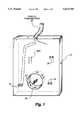
- FIG. 1is a perspective schematic view of a sensor platform in accordance with a first embodiment of the invention.
- FIG. 2is a block diagram of the first embodiment of the system in accordance with the invention.
- FIG. 3is a schematic side view of a vehicle showing potential locations for the sensor platform in accordance with the present invention.
- FIG. 4is a partial side view of a second embodiment of a sensor platform of the present invention.
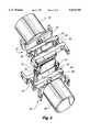
- FIG. 5is a perspective view of the second embodiment of the present invention.
- FIG. 6is a control block diagram of the second embodiment of the present invention.
- FIG. 7is front view of the display panel in the second embodiment of the present invention.
- FIG. 8is a schematic side view of an alternative collection apparatus of a system in accordance with the present invention.
- FIG. 9is a block diagram of a remote sensing embodiment of the system in accordance with the present invention.
- a first embodiment of the apparatus of the inventionincludes a platform 12 which is typically vertically mounted behind a vehicle wheel 14. This platform 12 replaces and also operates as a conventional mud flap on the vehicle 10.
- one of the objects of this inventionis to provide a unique multi-purpose mounting platform 12, such as is shown in FIG. 1, that enables the temporary use of materials 16 which are typically discharged from a vehicle wheel/road surface interface to measure certain characteristics of the materials that have left a roadway surface (surface materials), and to also determine certain characteristics of the surface itself.
- the surfaceis most commonly a road or aircraft runway surface. Throughout this specification, use of the terms surface, road, roadway, or runway are interchangeable and are used to generally mean any surface upon which a vehicle is operated or is operable.
- the manipulation of the characteristics of surface materialsfor instance freezing the surface material, is one efficient and accurate way to obtain information on the surface conditions as well as determine the conditions of loose surface material.
- Material volumetric buildupsuch as snow, ice, liquid solution, i.e., depth of material on the surface.
- the methodology of determining the characteristics described abovevaries with the characteristic being tested.
- the general type of material buildupmay be measured via resistivity and/or conductivity in conjunction with temperature.
- the chemical composition of the material on the road surfacemay be determined by spectrographic techniques, or by evaluation of EMR reflections.
- the percent of chemical(s) in a solution that has built up on a road surfacemay be determined by measuring the resistivity and/or conductivity of the collected material covering the sensor or by evaluation of EMR reflections.
- the freeze point of the solutionmay be determined by a software comparison, such as a table look-up, when the material components are known.
- the ambient temperatureis measured via a thermometer or thermocouple which could be remote from the platform.
- the temperature of the solution/material buildupis measured by any known appropriate sensor means such as a thermometer, thermocouple or infrared sensor preferably mounted on the platform 12.
- the freeze point of a solutioncan actually be determined by actually freezing the collected solution.
- the freeze pointis determined by monitoring a property of the solution that indicates that the freezing temperature is reached, such as changes in electrical conductivity. This could eliminate the need for a look-up table.
- the sensor platform 12can be made of a thermoplastic material, or sensor flap material such as urethanes or teflon, and which preferably has the following characteristics:
- pliable and flexible temperature rangeof plus 150-minus 40 F. degrees without melting or becoming brittle. Operating temperature of eighty degrees fahrenheit (80° F.) to minus forty degrees fahrenheit (-40° F.); and
- the sensor platform or flap 12, shown in FIG. 1,illustrates a variety of sensors mounted on or within it to illustrate the various mounting configurations for the purpose of making measurements or sensing certain characteristics of the material that has left the road surface as a result of turbulence or surface discharge behind the vehicle wheel.
- the platform 12is constructed to carry or have imbedded therein various sensors 18, 20, 22, and/or 24. These sensors, depending on their function, may protrude outside of or be recessed within the finished flap 12 so that they will be exposed to, or not exposed to, the material to be sensed, or will have access to the material to be sensed. As an alternative, the various sensors could be mounted with appropriate hardware onto an existing piece of flap material to achieve the same effect.
- sensors 18 and 20may be a conductivity detector and/or a resistance temperature detector (RTD) or a thermocouple (TC) which senses the temperature of the material on the surface of the flap 12 and the presence of conductive solutions in the material such as NaCl or KCl or MgCl 2 in order to determine the type of material buildup.
- RTDresistance temperature detector
- TCthermocouple
- the lead wires from the conductivity cell and/or the RTD or TCare either embedded in or mounted behind the flap 12 for protection from abrasion and moisture.
- Sensor 22may be a sensor such as an RTD or TC mounted within an aperture 26 in the flap 12.
- the aperture 26permits the passing air flow behind the wheel 14 to blow clear and thus ensure that new material continuously passes the sensor location.
- Other sensor locations in the aperture 26are shown in dashed lines.
- the aperture 26may also be used to direct flow of material past a sensor such as an EMR device.
- the sensor 22Amay alternatively be embedded in the flap 12 with the tip projecting to the front surface of the flap 12 to accurately measure the captured material temperature.
- Sensor 24may be a RTD or TC mounted either behind the flap 12 or embedded within it so as to be representative of the ambient temperature of the flap 12. Alternative sensor locations may be incorporated into the sides or top of the flap 12 as indicated by the "S" thereon.
- the flap 12is preferably mechanically attached to the vehicle 10.
- the sensor flap 12is designed to temporarily "catch" the discharge material from the vehicle's wheel 14.
- a separate sensor wheel 14Amay be provided as shown in FIG. 3, for producing material discharge to be collected by a flap 12A which carries the sensors for making the measurements concerning the surface that the vehicle is riding over as well as detecting any buildup that might be on the surface--even after the buildup has left the surface.
- the incident spray materialmust not cling to the flap or plug any pass-through holes as new samples must periodically be measured/sensed. Therefore, proper material selection is an important consideration in this first embodiment.
- the sensorsare connected to an in-cab display and control panel 28 via a cable 30 as shown in FIG. 2.
- the control panel 28is capable of controlling, communicating with, and powering the sensors as well as interpreting sensor data and preferably includes display/input devices which can display information, accept outside input, store commands, and retrieve data. Alarm and control functions are also displayed on this panel.
- interpreted datacould include a freeze point prediction or alert notice for the measured solution and/or material.
- FIGS. 4-7A second embodiment of the surface condition sensing system in accordance with the invention is shown in FIGS. 4-7.
- the system in accordance with the second embodimentis specifically directed to determining the freezing temperature of a surface material. It includes an apparatus 38 that collects material from the road surface into a chamber, freezes it, determines the freezing temperature, communicates the data appropriately to a display/control console, and then thaws the material, empties the chamber, and prepares for the next measurement cycle.
- the apparatus 38is mounted in a location on the platform 12 as disclosed above.
- the apparatus 38 associated with this systemis seen in a side view in FIG. 4.
- the apparatus 38comprises a support structure 40 made of any suitable material, for instance a laminate of a thermoplastic material and aluminum, and a capture and measurement portion 42 supported below and from the support structure 40.
- the capture portion 42comprises an elongated chamber 44 having an open top end 46 and an open bottom end 48 generally having an elongated oval cross section.
- the open top end 46is for receiving any surface material that collects above the top end 46 on the support structure 40.
- the top end 46 and bottom end 48 of the chamber 44are preferably made of a flexible material, such as plastic or rubber, which is preferably able to be selectively opened and pinched closed to allow material to flow in and out as desired.
- Selective opening and closing valve mechanisms 50are mounted to the apparatus at the appropriate positions adjacent the upper and lower ends 46 and 48.
- Each of the opening and closing mechanisms 50includes a pinch valve 52 and a solenoid 54.
- the top and bottom ends 46, 48 of the chamber 44are selectively opened and closed by pinch-valves 52.
- the upper solenoid 54When the upper solenoid 54 is energized, it extends a shaft 55 outward and pushes a first surface 56, engaging a flexible portion 58 of the chamber 44 adjacent the upper open end 46, from one side and drives the flexible portion 58 towards the other side, which is in contact with a stationary second surface 60.
- the open top end 46 of the chamberis thus pinched closed between the first and second surfaces 56 and 60, causing a preferably impermeable seal to be formed at the top end of the chamber.
- the bottom end 48 of the chamber 44is closed in a similar manner using a second solenoid operated pinch valve 52.
- the chamber 44has a central portion 62 of a predetermined length and width between the selective opening and closing mechanisms 50.
- This portion 62preferably has an elongated oval cross section and is made of a conductive material, such as copper.
- the central portion 62 of the chamber 44 comprising a conductive materialis thermally coupled to opposing plates of a thermo-electric heater/cooler 64 which controls the temperature of the central conductive chamber 44 using, for example, the well known Peltier effect.
- a heat sink 66surrounds the chamber 44, preferably on all sides, along the length of the chamber 44 to facilitate the heating and cooling process as a result of the operation of the thermo-electric heater/cooler 64.
- a liquid exiting aperture 68is formed in the chamber 44 above the first surface 56 to allow any surface material draining into the liquid capture gap 70 to exit the chamber 44 when the flexible portion 58 of the chamber 44 is closed during operation of the thermo-electric heater/cooler 64.
- the draining liquidflows down over the heat sinks 66, preferably thereby beneficially affecting the heat transfer capabilities of the heat sinks 66.
- this second apparatusmay be either automatic or manual. In automatic operation, the apparatus operates continuously or at a predetermined cycle frequency as determined by the user. In manual mode, the user actuates the apparatus each time road surface condition information is desired.
- This second embodiment of the road surface sensing systemis used to collect surface material and accurately determine the freezing point of such material regardless of material composition.
- the apparatusis positioned on the vehicle such that it is exposed to the spray of the surface material caused by the motion of the vehicle, as is schematically shown in FIG. 3.
- the apparatusmay be positioned behind front or rear wheels, or may optionally include a separate wheel or scoop device to pick up material from the road surface.
- the bottom end 48 of the chamber 44is closed.
- the surface material spraycontacts the support structure 40, runs down the support structure 40 under the influence of gravity into the liquid capture gap 70.
- the surface materialcollects in the chamber 44 either for a programmable predetermined period of time, preferably about 5 to 10 seconds, or until the appropriate liquid level is obtained, at which time the top end 46 is closed by closure of the upper pinch valve 52 to preclude entry of material that could contaminate the sample during measurement.
- thermo-electric cooler 64When a sufficient amount of surface material is collected in the chamber 44 and the upper pinch valve 52 is closed and the thermo-electric cooler 64 is activated to freeze the collected surface material. The electrical conductivity of the collected surface material is monitored in the chamber 44 during the cooling process to establish the freezing point of the surface material. This freezing point is communicated appropriately to the processor and display console 72, shown in FIG. 7.
- thermo-electric cooler 64is activated to heat the conductive chamber portion 62 to melt the surface material.
- the bottom end 48is then opened by de-energizing the lower pinch valve 52 to allow the surface material to exit the chamber 44. The process can then be repeated to obtain a new reading.
- automatic operation of the apparatus in accordance with this embodiment of the inventionproceeds as follows.
- the userplaces the automatic/manual selector switch 80 in the automatic position.
- a signal 82is sent to close the bottom valve and a signal 84 is provided to de-energize the upper solenoid valve 52 so that collected material may flow into the chamber 44.
- the control systemthen pauses for a predetermined amount of time, such as ten seconds, in block 86.
- a signal 88is sent to close the upper valve 52 in order to isolate the sensing portion 62 of the chamber 44.
- another programmable wait period 90 of a predetermined length of timeis conducted after which the processor tests whether the contents of the central portion 62 of the chamber 44 is conductive. This test of conductivity 92 is necessary in order to sense whether there is any material collected in the chamber. If the material collected in the chamber is conductive, a signal 94 is sent to turn on the thermo-electric heater/cooler 64 in the cooling mode. Conductivity is continually monitored in block 96 to determine a significant change in conductivity, as the material in the central portion 62 of the chamber 44 is cooled, which indicates that the threshold to freezing has been reached.
- This thresholdis normally indicated by a substantial change in magnitude of the conductivity signal. If the threshold of freezing is detected in block 96, the processor then sends a signal 98 to turn on the heater until it reaches a temperature substantially greater than the threshold, for example, about 50° Fahrenheit. When this temperature is reached, a control signal 100 is sent to de-energize both upper and lower solenoid valves 52 for a programmable period of time sufficient to permit the collected material to drain from the chamber 44, for example, ten seconds.
- the display consoleincludes an on/off switch 104, a start switch 106, a purge switch 108, and a display 110.
- Manual operation or automatic operationis selected by switch 80.
- the purge switch 108may be pressed by the operator. This de-energizes both inlet and outlet valves 52, allowing any materials contained in the chamber 44 to be discharged.
- the start switch 106is pressed and the automatic or manual control process shown in the flow chart in FIG. 6 is performed from block 82 through block 100.
- the processordetermines in block 112 whether switch 80 is in the automatic or manual position. If in the manual position, a signal is sent to leave both valves 52 open and await further manual instructions. If switch 80 is in the automatic position, however, the process is automatically directed to block 82 in which the bottom valve 52 is closed and the sample collection and evaluation process is repeated a programmable number of times.
- the apparatus in accordance with the second embodimentmay be modified to include a collection apparatus 120 that incorporates an endless belt 122.
- the endless belt 122moves in the direction of the arrow 124.
- Road debris thrown up by the vehiclemoves and impinges on belt 122 in the direction shown by arrow 126.
- the lower pulley 128is preferably either hydraulic motor driven or electrically driven.
- the upper pulley 130is preferably spring biased away from the motor driven pulley 128 to maintain tension on the belt 122.
- a collection hopper 132is positioned below the motor driven pulley 128 and discharges into the open upper end 46 of the collection chamber 44 above described.
- a scraper 134is positioned adjacent the front facing portion of the belt 122 before the belt 122 enters the hopper 132 so that as it enters the hopper 132, leaves and other solid debris may be scraped from the belt 122.
- a pinch idler pulley 136is mounted adjacent the motor driven pulley 128. As the belt moves around the pulleys counterclockwise as shown in FIG. 8, liquid picked up from the road is "squeegeed" into the hopper 132 as the belt 122 passes between idler pulley 136 and driven pulley 128.
- a spring-loaded clutch 138may also be provided on the motor driven pulley so that the collection apparatus 120 does not operate while the central portion 62 of the collection chamber 44 is isolated.
- FIG. 9A block diagram of a third embodiment of the sensing system in accordance with the present invention is illustrated in FIG. 9.
- This third embodimentis a completely remote sensing apparatus which is mounted on the vehicle.
- This system 200includes at least one electromagnetic radiation transceiver 202 which emits a ultra-wide band (UWB) impulse radar.
- UWBultra-wide band
- a very short electromagnetic impulseis propagated from transceiver 202 and echoes that reflect from the road surface 204 are evaluated.
- These reflected signalsare set to a depth processor 206, a density processor 208, and at least a chemical composition processor 210.
- the EMR reflected pulsemay be utilized directly by the depth processor 206 to determine the depth of any surface layer of material on the roadway.
- the density processor, and composition processors 208 and 210rely also on input from a database 212 to determine, by comparison to peak height or phase shift of the reflected signal versus the incident signal, an output which is unique to a particular chemical composition and density. Comparing these outputs to the database content produces or can result in quantitative density and composition information 214 which is, in turn, fed to computer 216 along with depth information 218.
- the depth 218is processed in the computer 216 to provide a display 220 with information necessary to determine what additional chemicals need to be deposited on the road surface in order to minimize the hazardous conditions.
- the computer 216may provide a direct output to a control device for automatically dispensing the appropriate amounts of chemicals to the road surface as the vehicle drives by.
- An infrared transceiver 222is also mounted on the vehicle and is directed toward the road surface.
- the transceiver 222provides an output to a road temperature processor 224 which in turn also feeds an output to the computer 216 indicative of the actual road surface temperature.
- the apparatus 200in accordance with the third embodiment of the present invention, may be compactly designed for unitary installation in the cab of a road maintenance vehicle, such as a salt truck, with the display 220 and a keyboard input device 226 integrated into the dashboard of the vehicle.
- the drivercan then input to the computer 216 desired deicing concentrations or other desired input information.
- the computer 216then can compare the actual composition and status of the material actually on the road and either display or automatically control the dispensing of additional chemicals to the road surface.
Landscapes
- Engineering & Computer Science (AREA)
- Mechanical Engineering (AREA)
- Life Sciences & Earth Sciences (AREA)
- Transportation (AREA)
- Biochemistry (AREA)
- Immunology (AREA)
- Chemical & Material Sciences (AREA)
- Analytical Chemistry (AREA)
- Physics & Mathematics (AREA)
- General Health & Medical Sciences (AREA)
- General Physics & Mathematics (AREA)
- Health & Medical Sciences (AREA)
- Pathology (AREA)
- Biodiversity & Conservation Biology (AREA)
- Environmental & Geological Engineering (AREA)
- Environmental Sciences (AREA)
- Investigating Or Analysing Materials By Optical Means (AREA)
- Investigating Or Analyzing Materials Using Thermal Means (AREA)
Abstract
Description
Claims (20)
Priority Applications (17)
| Application Number | Priority Date | Filing Date | Title |
|---|---|---|---|
| US08/660,232US5619193A (en) | 1996-06-07 | 1996-06-07 | Surface material and condition sensing system |
| CA002482691ACA2482691A1 (en) | 1995-10-06 | 1996-10-04 | Surface material and condition sensing system |
| AU73918/96AAU7391896A (en) | 1995-10-06 | 1996-10-04 | Surface material and condition sensing system |
| CA2233689ACA2233689C (en) | 1995-10-06 | 1996-10-04 | Surface material and condition sensing system |
| PCT/US1996/015985WO1997013234A1 (en) | 1995-10-06 | 1996-10-04 | Surface material and condition sensing system |
| US08/783,556US5745051A (en) | 1996-06-07 | 1997-01-14 | Surface material and condition sensing system |
| US08/879,921US5904296A (en) | 1996-06-07 | 1997-06-20 | Apparatus and system for synchronized application of one or more materials to a surface from a vehicle and control of a vehicle mounted variable positions snow removal device |
| US09/286,809US6173904B1 (en) | 1996-06-07 | 1999-04-06 | Apparatus and system for synchronized application of one or more materials to a surface from a vehicle and control of a vehicle mounted variable position snow removal device |
| US09/337,984US6535141B1 (en) | 1996-06-07 | 1999-06-22 | Vehicle mounted travel surface and weather condition monitoring system |
| US09/862,652US6938829B2 (en) | 1996-06-07 | 2001-05-21 | Apparatus and system for synchronized application of one or more materials to a surface from a vehicle and control of a vehicle mounted variable position snow removal device |
| US09/953,379US6538578B1 (en) | 1996-06-07 | 2001-09-14 | Vehicle mounted travel surface and weather condition monitoring system |
| US10/379,119US6977597B2 (en) | 1995-06-08 | 2003-03-03 | Vehicle mounted travel surface and weather condition monitoring system |
| US11/150,940US7839301B2 (en) | 1995-06-08 | 2005-06-13 | Surface condition sensing and treatment systems, and associated methods |
| US11/273,364US7164365B2 (en) | 1995-06-08 | 2005-11-14 | Vehicle mounted travel surface and weather condition monitoring system |
| US11/513,697US7400267B1 (en) | 1995-06-08 | 2006-08-31 | Methods for determining need for treating a vehicle travel surface |
| US11/932,240US7683804B2 (en) | 1995-06-08 | 2007-10-31 | Methods for determining need for treating a vehicle travel surface |
| US12/726,993US8044823B2 (en) | 1995-06-08 | 2010-03-18 | Systems and method for monitoring and controlling a vehicle travel surface |
Applications Claiming Priority (1)
| Application Number | Priority Date | Filing Date | Title |
|---|---|---|---|
| US08/660,232US5619193A (en) | 1996-06-07 | 1996-06-07 | Surface material and condition sensing system |
Related Parent Applications (1)
| Application Number | Title | Priority Date | Filing Date |
|---|---|---|---|
| US11/150,940ContinuationUS7839301B2 (en) | 1995-06-08 | 2005-06-13 | Surface condition sensing and treatment systems, and associated methods |
Related Child Applications (1)
| Application Number | Title | Priority Date | Filing Date |
|---|---|---|---|
| US08/783,556ContinuationUS5745051A (en) | 1995-06-08 | 1997-01-14 | Surface material and condition sensing system |
Publications (1)
| Publication Number | Publication Date |
|---|---|
| US5619193Atrue US5619193A (en) | 1997-04-08 |
Family
ID=24648672
Family Applications (2)
| Application Number | Title | Priority Date | Filing Date |
|---|---|---|---|
| US08/660,232Expired - LifetimeUS5619193A (en) | 1995-06-08 | 1996-06-07 | Surface material and condition sensing system |
| US08/783,556Expired - LifetimeUS5745051A (en) | 1995-06-08 | 1997-01-14 | Surface material and condition sensing system |
Family Applications After (1)
| Application Number | Title | Priority Date | Filing Date |
|---|---|---|---|
| US08/783,556Expired - LifetimeUS5745051A (en) | 1995-06-08 | 1997-01-14 | Surface material and condition sensing system |
Country Status (1)
| Country | Link |
|---|---|
| US (2) | US5619193A (en) |
Cited By (38)
| Publication number | Priority date | Publication date | Assignee | Title |
|---|---|---|---|---|
| US5736939A (en)* | 1996-12-11 | 1998-04-07 | Caterpillar Inc. | Apparatus and method for determing a condition of a road |
| US5745051A (en)* | 1996-06-07 | 1998-04-28 | Doherty; John A. | Surface material and condition sensing system |
| US5774070A (en)* | 1995-11-22 | 1998-06-30 | Rendon; Edward | Method and system for the precise thermal mapping of roads, runways and the like for wintertime safety monitoring and maintenance |
| US5897802A (en)* | 1996-12-10 | 1999-04-27 | Jones; Robert C. | Heated debris shield |
| US5904296A (en)* | 1996-06-07 | 1999-05-18 | John A. Doherty | Apparatus and system for synchronized application of one or more materials to a surface from a vehicle and control of a vehicle mounted variable positions snow removal device |
| US6154699A (en)* | 1995-10-06 | 2000-11-28 | Williams; Brian | Gritting systems and methods |
| US6166657A (en)* | 1995-03-21 | 2000-12-26 | Commercial Vehicle Systems, Inc. | Imminent icing condition enunciator |
| US6173904B1 (en) | 1996-06-07 | 2001-01-16 | John A. Doherty | Apparatus and system for synchronized application of one or more materials to a surface from a vehicle and control of a vehicle mounted variable position snow removal device |
| US6535141B1 (en) | 1996-06-07 | 2003-03-18 | John A. Doherty | Vehicle mounted travel surface and weather condition monitoring system |
| US20040195357A1 (en)* | 1996-06-07 | 2004-10-07 | Doherty John A. | Apparatus and system for synchronized application of one or more materials to a surface from a vehicle and control of a vehicle mounted variable position snow removal device |
| US20040250612A1 (en)* | 2001-09-19 | 2004-12-16 | Laura Stridiron | System for measuring material properties from a moving construction vehicle |
| US20050246088A1 (en)* | 1995-06-08 | 2005-11-03 | Doherty John A | Surface condition sensing and treatment systems, and associated methods |
| US7249030B2 (en) | 2001-08-24 | 2007-07-24 | Sopko Iii Victor | Method and system for providing maintenance and management services for long-term capital equipment or fixtures by providing a performance warranty |
| US7301478B1 (en)* | 2006-03-03 | 2007-11-27 | Overland Safety Technologies Corporation | Vehicle safety warning device |
| US20080041139A1 (en)* | 2006-08-15 | 2008-02-21 | Marko Baller | Early fouling detection |
| US20080157943A1 (en)* | 2005-02-25 | 2008-07-03 | Iwapi Inc. | Smart modem device for vehicular and roadside applications |
| US20080234878A1 (en)* | 1993-06-08 | 2008-09-25 | Raymond Anthony Joao | Control, monitoring and/or security apparatus and method |
| US20080306799A1 (en)* | 2001-08-24 | 2008-12-11 | Tremco, Inc. | Method and system for providing maintenance & management services for long-term capital assets, equipment or fixtures by providing a warranty |
| US20090173839A1 (en)* | 2008-01-03 | 2009-07-09 | Iwapi Inc. | Integrated rail efficiency and safety support system |
| US20100004862A1 (en)* | 2008-07-01 | 2010-01-07 | Quixote Transporation Technologies, Inc. | Mobile environmental detector |
| US20100004863A1 (en)* | 2008-07-01 | 2010-01-07 | Spencer Ladow | Mobile environmental detector |
| US20110040518A1 (en)* | 2009-08-11 | 2011-02-17 | Schmitz-Huebsch Axel | Non-contact freezing temperature determination |
| US8275522B1 (en) | 2007-06-29 | 2012-09-25 | Concaten, Inc. | Information delivery and maintenance system for dynamically generated and updated data pertaining to road maintenance vehicles and other related information |
| US20130035825A1 (en)* | 2007-03-20 | 2013-02-07 | Enpulz, L.L.C. | Look ahead vehicle suspension system |
| ITTO20121153A1 (en)* | 2012-12-27 | 2014-06-28 | Febo S R L | METHOD AND MEASUREMENT DEVICE TO DETERMINE SALINITY ON A ROAD COVER, AND VEHICLE PROVIDED WITH SUCH A MEASURING DEVICE |
| US8902081B2 (en) | 2010-06-02 | 2014-12-02 | Concaten, Inc. | Distributed maintenance decision and support system and method |
| US9601015B2 (en) | 2005-02-25 | 2017-03-21 | Concaten, Inc. | Maintenance decision support system and method for vehicular and roadside applications |
| US9864957B2 (en) | 2007-06-29 | 2018-01-09 | Concaten, Inc. | Information delivery and maintenance system for dynamically generated and updated data pertaining to road maintenance vehicles and other related information |
| US20180011039A1 (en)* | 2015-01-15 | 2018-01-11 | Transtech Systems, Inc. | Measurement and monitoring of physical properties of material under test (mut) from a vehicle |
| JP2018054542A (en)* | 2016-09-30 | 2018-04-05 | シャープ株式会社 | Moving body |
| US10011247B2 (en) | 1996-03-27 | 2018-07-03 | Gtj Ventures, Llc | Control, monitoring and/or security apparatus and method |
| US10562492B2 (en) | 2002-05-01 | 2020-02-18 | Gtj Ventures, Llc | Control, monitoring and/or security apparatus and method |
| US10796268B2 (en) | 2001-01-23 | 2020-10-06 | Gtj Ventures, Llc | Apparatus and method for providing shipment information |
| CN113026643A (en)* | 2020-12-16 | 2021-06-25 | 长沙中联重科环境产业有限公司 | Sprinkling control system and method and sprinkling truck |
| US11192498B2 (en)* | 2016-06-22 | 2021-12-07 | Moran SACHKO | Apparatus for detecting hazardous objects within a designated distance from a surface |
| US11351961B2 (en)* | 2020-01-29 | 2022-06-07 | Ford Global Technologies, Llc | Proximity-based vehicle security systems and methods |
| CN115491956A (en)* | 2022-10-18 | 2022-12-20 | 百色枢纽通航投资有限公司 | A flatness detection device for highway engineering |
| CN116289448A (en)* | 2023-04-10 | 2023-06-23 | 中交二公局第一工程有限公司 | A road level detection device for bridge construction |
Families Citing this family (12)
| Publication number | Priority date | Publication date | Assignee | Title |
|---|---|---|---|---|
| US6330519B1 (en) | 1998-11-19 | 2001-12-11 | Sentec Corporation | Visibility sensor system |
| US6166645A (en)* | 1999-01-13 | 2000-12-26 | Blaney; Kevin | Road surface friction detector and method for vehicles |
| US6749364B1 (en)* | 1999-05-19 | 2004-06-15 | Blaw-Knox Construction Equipment Corporation | Temperature sensing for controlling paving and compaction operations |
| US6222454B1 (en)* | 1999-07-01 | 2001-04-24 | Goal Electronics Inc. | Non-contacting temperature sensing device |
| US6609066B2 (en) | 2002-01-24 | 2003-08-19 | Ford Global Technologies, Llc | Method and apparatus for activating a crash countermeasure in response to the braking capability of a vehicle |
| US7421894B2 (en)* | 2005-07-14 | 2008-09-09 | Dale Keep | Sensors and associated methods, including surface condition sensors |
| US7629801B2 (en)* | 2005-07-14 | 2009-12-08 | Zydax, Llc | Sensing system for use in detecting a surface condition of a roadway surface |
| US7591608B2 (en)* | 2006-06-29 | 2009-09-22 | Hall David R | Checking density while compacting |
| FR2957666B1 (en)* | 2010-03-16 | 2012-06-01 | Michelin Soc Tech | DEVICE FOR MEASURING THE TEMPERATURE OF WATER COVERING A PAVEMENT |
| PL2789740T3 (en)* | 2013-04-12 | 2018-05-30 | Joseph Vögele AG | Base temperature measurement by means of a road finisher |
| PL2789741T5 (en) | 2013-04-12 | 2019-05-31 | Voegele Ag J | Finisher with a thermographic device |
| CN104477090A (en)* | 2014-11-19 | 2015-04-01 | 柳州航盛科技有限公司 | Traffic safety system for vehicle under complex road condition |
Citations (5)
| Publication number | Priority date | Publication date | Assignee | Title |
|---|---|---|---|---|
| US4274091A (en)* | 1978-03-09 | 1981-06-16 | Decker Peter W | Road surface ice detector and method for vehicles |
| US4492952A (en)* | 1982-04-12 | 1985-01-08 | Atlas Electronics International | Automotive driving condition alarm system |
| US4678056A (en)* | 1984-10-09 | 1987-07-07 | Nissan Motor Co., Ltd. | Part time four wheel drive vehicle with road surface condition sensor |
| US5416476A (en)* | 1991-11-29 | 1995-05-16 | Rendon; Edward | Method and system for detecting potential icy conditions on roads |
| US5521594A (en)* | 1993-02-25 | 1996-05-28 | Mitsubishi Denki Kabushiki Kaisha | Road surface condition detector for automotive vehicle |
Family Cites Families (3)
| Publication number | Priority date | Publication date | Assignee | Title |
|---|---|---|---|---|
| US5416475A (en)* | 1993-07-23 | 1995-05-16 | Schlumberger Industries, Inc. | Remote meter reading receptacle for pit lid mounting |
| US5447272A (en)* | 1994-02-22 | 1995-09-05 | Ask; Bernard J. | Automatic deicer spreader |
| US5619193A (en)* | 1996-06-07 | 1997-04-08 | John A. Doherty | Surface material and condition sensing system |
- 1996
- 1996-06-07USUS08/660,232patent/US5619193A/ennot_activeExpired - Lifetime
- 1997
- 1997-01-14USUS08/783,556patent/US5745051A/ennot_activeExpired - Lifetime
Patent Citations (5)
| Publication number | Priority date | Publication date | Assignee | Title |
|---|---|---|---|---|
| US4274091A (en)* | 1978-03-09 | 1981-06-16 | Decker Peter W | Road surface ice detector and method for vehicles |
| US4492952A (en)* | 1982-04-12 | 1985-01-08 | Atlas Electronics International | Automotive driving condition alarm system |
| US4678056A (en)* | 1984-10-09 | 1987-07-07 | Nissan Motor Co., Ltd. | Part time four wheel drive vehicle with road surface condition sensor |
| US5416476A (en)* | 1991-11-29 | 1995-05-16 | Rendon; Edward | Method and system for detecting potential icy conditions on roads |
| US5521594A (en)* | 1993-02-25 | 1996-05-28 | Mitsubishi Denki Kabushiki Kaisha | Road surface condition detector for automotive vehicle |
Non-Patent Citations (3)
| Title |
|---|
| Data sheet D251, Aanderaa Instruments, Mar. 1995.* |
| UCRL MI 120916, Lawrence Livermore National laboratory, Jun. 7, 1995.* |
| UCRL-MI-120916, Lawrence Livermore National laboratory, Jun. 7, 1995. |
Cited By (72)
| Publication number | Priority date | Publication date | Assignee | Title |
|---|---|---|---|---|
| US20080234878A1 (en)* | 1993-06-08 | 2008-09-25 | Raymond Anthony Joao | Control, monitoring and/or security apparatus and method |
| US6166657A (en)* | 1995-03-21 | 2000-12-26 | Commercial Vehicle Systems, Inc. | Imminent icing condition enunciator |
| US6977597B2 (en) | 1995-06-08 | 2005-12-20 | Doherty John A | Vehicle mounted travel surface and weather condition monitoring system |
| US20030178501A1 (en)* | 1995-06-08 | 2003-09-25 | Doherty John A. | Vehicle mounted travel surface and weather condition monitoring system |
| US7839301B2 (en) | 1995-06-08 | 2010-11-23 | Western Strategic Products, Llc | Surface condition sensing and treatment systems, and associated methods |
| US20050246088A1 (en)* | 1995-06-08 | 2005-11-03 | Doherty John A | Surface condition sensing and treatment systems, and associated methods |
| US6154699A (en)* | 1995-10-06 | 2000-11-28 | Williams; Brian | Gritting systems and methods |
| US5774070A (en)* | 1995-11-22 | 1998-06-30 | Rendon; Edward | Method and system for the precise thermal mapping of roads, runways and the like for wintertime safety monitoring and maintenance |
| US10011247B2 (en) | 1996-03-27 | 2018-07-03 | Gtj Ventures, Llc | Control, monitoring and/or security apparatus and method |
| US20040195357A1 (en)* | 1996-06-07 | 2004-10-07 | Doherty John A. | Apparatus and system for synchronized application of one or more materials to a surface from a vehicle and control of a vehicle mounted variable position snow removal device |
| US6538578B1 (en) | 1996-06-07 | 2003-03-25 | John A. Doherty | Vehicle mounted travel surface and weather condition monitoring system |
| US6535141B1 (en) | 1996-06-07 | 2003-03-18 | John A. Doherty | Vehicle mounted travel surface and weather condition monitoring system |
| US6938829B2 (en) | 1996-06-07 | 2005-09-06 | John A. Doherty | Apparatus and system for synchronized application of one or more materials to a surface from a vehicle and control of a vehicle mounted variable position snow removal device |
| US6173904B1 (en) | 1996-06-07 | 2001-01-16 | John A. Doherty | Apparatus and system for synchronized application of one or more materials to a surface from a vehicle and control of a vehicle mounted variable position snow removal device |
| US5745051A (en)* | 1996-06-07 | 1998-04-28 | Doherty; John A. | Surface material and condition sensing system |
| US5904296A (en)* | 1996-06-07 | 1999-05-18 | John A. Doherty | Apparatus and system for synchronized application of one or more materials to a surface from a vehicle and control of a vehicle mounted variable positions snow removal device |
| US5897802A (en)* | 1996-12-10 | 1999-04-27 | Jones; Robert C. | Heated debris shield |
| US5736939A (en)* | 1996-12-11 | 1998-04-07 | Caterpillar Inc. | Apparatus and method for determing a condition of a road |
| US10796268B2 (en) | 2001-01-23 | 2020-10-06 | Gtj Ventures, Llc | Apparatus and method for providing shipment information |
| US7249030B2 (en) | 2001-08-24 | 2007-07-24 | Sopko Iii Victor | Method and system for providing maintenance and management services for long-term capital equipment or fixtures by providing a performance warranty |
| US20080306799A1 (en)* | 2001-08-24 | 2008-12-11 | Tremco, Inc. | Method and system for providing maintenance & management services for long-term capital assets, equipment or fixtures by providing a warranty |
| US20070201951A1 (en)* | 2001-09-19 | 2007-08-30 | Ingersoll-Rand Company | System for measuring material properties from a moving construction vehicle |
| US20040250612A1 (en)* | 2001-09-19 | 2004-12-16 | Laura Stridiron | System for measuring material properties from a moving construction vehicle |
| US7226239B2 (en)* | 2001-09-19 | 2007-06-05 | Ingersoll-Rand Company | System for measuring material properties from a moving construction vehicle |
| US7575395B2 (en) | 2001-09-19 | 2009-08-18 | Volvo Construction Equipment Ab | System for measuring material properties from a moving construction vehicle |
| US10562492B2 (en) | 2002-05-01 | 2020-02-18 | Gtj Ventures, Llc | Control, monitoring and/or security apparatus and method |
| US11386782B2 (en) | 2005-02-25 | 2022-07-12 | Concaten, Inc. | Maintenance decision support system and method for vehicular and roadside applications |
| US7714705B2 (en) | 2005-02-25 | 2010-05-11 | Iwapi Inc. | Maintenance decision support system and method |
| US20080157943A1 (en)* | 2005-02-25 | 2008-07-03 | Iwapi Inc. | Smart modem device for vehicular and roadside applications |
| US9601015B2 (en) | 2005-02-25 | 2017-03-21 | Concaten, Inc. | Maintenance decision support system and method for vehicular and roadside applications |
| US8120473B2 (en) | 2005-02-25 | 2012-02-21 | Concaten, Inc. | Smart modem device for vehicular and roadside applications |
| US9035755B2 (en) | 2005-02-25 | 2015-05-19 | Concaten, Inc. | Maintenance decision support system and method for vehicular and roadside applications |
| US8497769B2 (en) | 2005-02-25 | 2013-07-30 | Concaten, Inc. | Maintenance decision support system and method for vehicular and roadside applications |
| US8284037B2 (en) | 2005-02-25 | 2012-10-09 | Concaten, Inc. | Maintenance decision support system and method for vehicular and roadside applications |
| US7301478B1 (en)* | 2006-03-03 | 2007-11-27 | Overland Safety Technologies Corporation | Vehicle safety warning device |
| US7652586B2 (en)* | 2006-08-15 | 2010-01-26 | General Electric Company | Early fouling detection |
| US20080041139A1 (en)* | 2006-08-15 | 2008-02-21 | Marko Baller | Early fouling detection |
| US20130035825A1 (en)* | 2007-03-20 | 2013-02-07 | Enpulz, L.L.C. | Look ahead vehicle suspension system |
| US8818629B2 (en)* | 2007-03-20 | 2014-08-26 | Enpulz, L.L.C. | Look ahead vehicle suspension system |
| US10733542B2 (en) | 2007-06-29 | 2020-08-04 | Concaten, Inc. | Information delivery and maintenance system for dynamically generated and updated data pertaining to road maintenance vehicles and other related information |
| US12299604B2 (en) | 2007-06-29 | 2025-05-13 | Concaten, Inc. | Information delivery and maintenance system for dynamically generated and updated data pertaining to road maintenance vehicles and other related information |
| US8583333B2 (en) | 2007-06-29 | 2013-11-12 | Concaten, Inc. | Information delivery and maintenance system for dynamically generated and updated data pertaining to road maintenance vehicles and other related information |
| US11270231B2 (en) | 2007-06-29 | 2022-03-08 | Concaten, Inc. | Information delivery and maintenance system for dynamically generated and updated data pertaining to road maintenance vehicles and other related information |
| US8275522B1 (en) | 2007-06-29 | 2012-09-25 | Concaten, Inc. | Information delivery and maintenance system for dynamically generated and updated data pertaining to road maintenance vehicles and other related information |
| US9864957B2 (en) | 2007-06-29 | 2018-01-09 | Concaten, Inc. | Information delivery and maintenance system for dynamically generated and updated data pertaining to road maintenance vehicles and other related information |
| US10275724B2 (en) | 2007-06-29 | 2019-04-30 | Concaten, Inc. | Information delivery and maintenance system for dynamically generated and updated data pertaining to road maintenance vehicles and other related information |
| US20090173839A1 (en)* | 2008-01-03 | 2009-07-09 | Iwapi Inc. | Integrated rail efficiency and safety support system |
| US8979363B2 (en) | 2008-01-03 | 2015-03-17 | Concaten, Inc. | Integrated rail efficiency and safety support system |
| US8231270B2 (en) | 2008-01-03 | 2012-07-31 | Concaten, Inc. | Integrated rail efficiency and safety support system |
| US9989426B2 (en) | 2008-01-03 | 2018-06-05 | Concaten, Inc. | Integrated rail efficiency and safety support system |
| US10352779B2 (en) | 2008-01-03 | 2019-07-16 | Concaten, Inc. | Integrated rail efficiency and safety support system |
| US20100004862A1 (en)* | 2008-07-01 | 2010-01-07 | Quixote Transporation Technologies, Inc. | Mobile environmental detector |
| US20100004863A1 (en)* | 2008-07-01 | 2010-01-07 | Spencer Ladow | Mobile environmental detector |
| CN101995417B (en)* | 2009-08-11 | 2014-07-23 | G·卢夫特·梅斯调节技术有限责任公司 | Contact-less freezing temperature determination |
| CN101995417A (en)* | 2009-08-11 | 2011-03-30 | G·卢夫特·梅斯调节技术有限责任公司 | Contact-less freezing temperature determination |
| US20110040518A1 (en)* | 2009-08-11 | 2011-02-17 | Schmitz-Huebsch Axel | Non-contact freezing temperature determination |
| US8838407B2 (en) | 2009-08-11 | 2014-09-16 | G. Lufft Meβ-Und Regeltechnik GmbH | Non-contact freezing temperature determination |
| US9373258B2 (en) | 2010-06-02 | 2016-06-21 | Concaten, Inc. | Distributed maintenance decision and support system and method |
| US10410517B2 (en) | 2010-06-02 | 2019-09-10 | Concaten, Inc. | Distributed maintenance decision and support system and method |
| US12183194B2 (en) | 2010-06-02 | 2024-12-31 | Concaten, Inc. | Distributed maintenance decision and support system and method |
| US10008112B2 (en) | 2010-06-02 | 2018-06-26 | Concaten, Inc. | Distributed maintenance decision and support system and method |
| US8902081B2 (en) | 2010-06-02 | 2014-12-02 | Concaten, Inc. | Distributed maintenance decision and support system and method |
| ITTO20121153A1 (en)* | 2012-12-27 | 2014-06-28 | Febo S R L | METHOD AND MEASUREMENT DEVICE TO DETERMINE SALINITY ON A ROAD COVER, AND VEHICLE PROVIDED WITH SUCH A MEASURING DEVICE |
| US20180011039A1 (en)* | 2015-01-15 | 2018-01-11 | Transtech Systems, Inc. | Measurement and monitoring of physical properties of material under test (mut) from a vehicle |
| US10739287B2 (en)* | 2015-01-15 | 2020-08-11 | Transtech Systems, Inc. | Measurement and monitoring of physical properties of material under test (MUT) from a vehicle |
| US11192498B2 (en)* | 2016-06-22 | 2021-12-07 | Moran SACHKO | Apparatus for detecting hazardous objects within a designated distance from a surface |
| JP2018054542A (en)* | 2016-09-30 | 2018-04-05 | シャープ株式会社 | Moving body |
| CN107878596A (en)* | 2016-09-30 | 2018-04-06 | 夏普株式会社 | moving body |
| US11351961B2 (en)* | 2020-01-29 | 2022-06-07 | Ford Global Technologies, Llc | Proximity-based vehicle security systems and methods |
| CN113026643A (en)* | 2020-12-16 | 2021-06-25 | 长沙中联重科环境产业有限公司 | Sprinkling control system and method and sprinkling truck |
| CN115491956A (en)* | 2022-10-18 | 2022-12-20 | 百色枢纽通航投资有限公司 | A flatness detection device for highway engineering |
| CN116289448A (en)* | 2023-04-10 | 2023-06-23 | 中交二公局第一工程有限公司 | A road level detection device for bridge construction |
Also Published As
| Publication number | Publication date |
|---|---|
| US5745051A (en) | 1998-04-28 |
Similar Documents
| Publication | Publication Date | Title |
|---|---|---|
| US5619193A (en) | Surface material and condition sensing system | |
| US6538578B1 (en) | Vehicle mounted travel surface and weather condition monitoring system | |
| US7400267B1 (en) | Methods for determining need for treating a vehicle travel surface | |
| CA2233689C (en) | Surface material and condition sensing system | |
| US3836846A (en) | Ice detection apparatus employing microwave reflectance | |
| KR101404834B1 (en) | METHOD AND APPARATUS FOR Predicting Sliding Friction of Road Surface, and Storage Medium Saving the Program | |
| EP1309484B1 (en) | Liquid water content measurement apparatus and method | |
| KR101431707B1 (en) | method of classification and quantification using data of X band dual polarization radar | |
| US5852243A (en) | Method and apparatus for detecting a road pavement surface condition | |
| US6166657A (en) | Imminent icing condition enunciator | |
| US7090392B2 (en) | Roadway freezing point monitoring system and method | |
| Le et al. | Hydrometeor profile characterization method for dual-frequency precipitation radar onboard the GPM | |
| US6608489B2 (en) | Device, and method of its use, for concurrent real time alerting to accumulation of material upon multiple areas of a surface | |
| Brustad et al. | A field study of sensors for winter road assessment | |
| JP7256499B2 (en) | Measuring method and measuring device for road surface water film thickness | |
| JP2000241563A (en) | Road surface freeze determination method and device, and road surface freeze prediction method and device. | |
| CA2301731C (en) | Method and device for generating a signal according to a liquid film on a surface | |
| CA2482691A1 (en) | Surface material and condition sensing system | |
| RU2232427C2 (en) | Method and alarm device for generating alarm signal about icy conditions of roads | |
| CA2312453A1 (en) | Vehicle mounted travel surface and weather condition monitoring system | |
| RU2745904C1 (en) | Device for monitoring the condition of road and airfield pavement | |
| KR20210086419A (en) | Vehicle type rainfall observation device | |
| CN110095435A (en) | A kind of detection method of non-contact road surface black ice state | |
| EP2835291B1 (en) | Method for the determination of the precipitation intensity from a moving vehicle/boat, and system for the space-time characterization of a precipitation field on wide territory areas | |
| Donovan et al. | Vehicle detection and speed estimation with PIR sensors |
Legal Events
| Date | Code | Title | Description |
|---|---|---|---|
| AS | Assignment | Owner name:DOHERTY, JOHN A., COLORADO Free format text:ASSIGNMENT OF ASSIGNORS INTEREST;ASSIGNORS:KALBFLEISCH, CHARLES A.;KEITHLEY, DONALD P.;COLLINS, WILLIAM J.;REEL/FRAME:008029/0686 Effective date:19960628 | |
| STCF | Information on status: patent grant | Free format text:PATENTED CASE | |
| FPAY | Fee payment | Year of fee payment:4 | |
| FPAY | Fee payment | Year of fee payment:8 | |
| AS | Assignment | Owner name:WESTERN STRATEGIC PRODUCTS, LLC, COLORADO Free format text:ASSIGNMENT OF ASSIGNORS INTEREST;ASSIGNOR:DOHERTY, JOHN A.;REEL/FRAME:015452/0901 Effective date:20041207 | |
| AS | Assignment | Owner name:DOHERTY, JOHN A., COLORADO Free format text:QUITCLAIM DEED;ASSIGNOR:WESTERN STRATEGIC PRODUCTS, LLC;REEL/FRAME:016274/0908 Effective date:20050615 | |
| FPAY | Fee payment | Year of fee payment:12 | |
| AS | Assignment | Owner name:WESTERN STRATEGIC PRODUCTS, LLC, COLORADO Free format text:ASSIGNMENT OF ASSIGNORS INTEREST;ASSIGNOR:DOHERTY, JOHN A.;REEL/FRAME:021029/0510 Effective date:20050923 Owner name:WESTERN STRATEGIC PRODUCTS, LLC,COLORADO Free format text:ASSIGNMENT OF ASSIGNORS INTEREST;ASSIGNOR:DOHERTY, JOHN A.;REEL/FRAME:021029/0510 Effective date:20050923 | |
| AS | Assignment | Owner name:WEATHER INSIGHTS LLC, OHIO Free format text:ASSIGNMENT OF ASSIGNORS INTEREST;ASSIGNOR:WESTERN STRATEGIC PRODUCTS LLC;REEL/FRAME:035120/0579 Effective date:20150309 |