US5618179A - Driver training system and method with performance data feedback - Google Patents
Driver training system and method with performance data feedbackDownload PDFInfo
- Publication number
- US5618179A US5618179AUS08/339,478US33947894AUS5618179AUS 5618179 AUS5618179 AUS 5618179AUS 33947894 AUS33947894 AUS 33947894AUS 5618179 AUS5618179 AUS 5618179A
- Authority
- US
- United States
- Prior art keywords
- vehicle
- input device
- simulated
- computer
- user
- Prior art date
- Legal status (The legal status is an assumption and is not a legal conclusion. Google has not performed a legal analysis and makes no representation as to the accuracy of the status listed.)
- Expired - Lifetime
Links
Images


Classifications
- G—PHYSICS
- G09—EDUCATION; CRYPTOGRAPHY; DISPLAY; ADVERTISING; SEALS
- G09B—EDUCATIONAL OR DEMONSTRATION APPLIANCES; APPLIANCES FOR TEACHING, OR COMMUNICATING WITH, THE BLIND, DEAF OR MUTE; MODELS; PLANETARIA; GLOBES; MAPS; DIAGRAMS
- G09B9/00—Simulators for teaching or training purposes
- G09B9/02—Simulators for teaching or training purposes for teaching control of vehicles or other craft
- G09B9/04—Simulators for teaching or training purposes for teaching control of vehicles or other craft for teaching control of land vehicles
- A—HUMAN NECESSITIES
- A63—SPORTS; GAMES; AMUSEMENTS
- A63F—CARD, BOARD, OR ROULETTE GAMES; INDOOR GAMES USING SMALL MOVING PLAYING BODIES; VIDEO GAMES; GAMES NOT OTHERWISE PROVIDED FOR
- A63F13/00—Video games, i.e. games using an electronically generated display having two or more dimensions
- A63F13/20—Input arrangements for video game devices
- A63F13/24—Constructional details thereof, e.g. game controllers with detachable joystick handles
- A63F13/245—Constructional details thereof, e.g. game controllers with detachable joystick handles specially adapted to a particular type of game, e.g. steering wheels
- A—HUMAN NECESSITIES
- A63—SPORTS; GAMES; AMUSEMENTS
- A63F—CARD, BOARD, OR ROULETTE GAMES; INDOOR GAMES USING SMALL MOVING PLAYING BODIES; VIDEO GAMES; GAMES NOT OTHERWISE PROVIDED FOR
- A63F13/00—Video games, i.e. games using an electronically generated display having two or more dimensions
- A63F13/80—Special adaptations for executing a specific game genre or game mode
- A63F13/803—Driving vehicles or craft, e.g. cars, airplanes, ships, robots or tanks
- A—HUMAN NECESSITIES
- A63—SPORTS; GAMES; AMUSEMENTS
- A63F—CARD, BOARD, OR ROULETTE GAMES; INDOOR GAMES USING SMALL MOVING PLAYING BODIES; VIDEO GAMES; GAMES NOT OTHERWISE PROVIDED FOR
- A63F13/00—Video games, i.e. games using an electronically generated display having two or more dimensions
- A63F13/90—Constructional details or arrangements of video game devices not provided for in groups A63F13/20 or A63F13/25, e.g. housing, wiring, connections or cabinets
- G—PHYSICS
- G06—COMPUTING OR CALCULATING; COUNTING
- G06T—IMAGE DATA PROCESSING OR GENERATION, IN GENERAL
- G06T15/00—3D [Three Dimensional] image rendering
- G—PHYSICS
- G06—COMPUTING OR CALCULATING; COUNTING
- G06T—IMAGE DATA PROCESSING OR GENERATION, IN GENERAL
- G06T15/00—3D [Three Dimensional] image rendering
- G06T15/50—Lighting effects
- G—PHYSICS
- G09—EDUCATION; CRYPTOGRAPHY; DISPLAY; ADVERTISING; SEALS
- G09B—EDUCATIONAL OR DEMONSTRATION APPLIANCES; APPLIANCES FOR TEACHING, OR COMMUNICATING WITH, THE BLIND, DEAF OR MUTE; MODELS; PLANETARIA; GLOBES; MAPS; DIAGRAMS
- G09B9/00—Simulators for teaching or training purposes
- G09B9/02—Simulators for teaching or training purposes for teaching control of vehicles or other craft
- G09B9/04—Simulators for teaching or training purposes for teaching control of vehicles or other craft for teaching control of land vehicles
- G09B9/05—Simulators for teaching or training purposes for teaching control of vehicles or other craft for teaching control of land vehicles the view from a vehicle being simulated
- A—HUMAN NECESSITIES
- A63—SPORTS; GAMES; AMUSEMENTS
- A63F—CARD, BOARD, OR ROULETTE GAMES; INDOOR GAMES USING SMALL MOVING PLAYING BODIES; VIDEO GAMES; GAMES NOT OTHERWISE PROVIDED FOR
- A63F2300/00—Features of games using an electronically generated display having two or more dimensions, e.g. on a television screen, showing representations related to the game
- A63F2300/10—Features of games using an electronically generated display having two or more dimensions, e.g. on a television screen, showing representations related to the game characterized by input arrangements for converting player-generated signals into game device control signals
- A63F2300/1037—Features of games using an electronically generated display having two or more dimensions, e.g. on a television screen, showing representations related to the game characterized by input arrangements for converting player-generated signals into game device control signals being specially adapted for converting control signals received from the game device into a haptic signal, e.g. using force feedback
- A—HUMAN NECESSITIES
- A63—SPORTS; GAMES; AMUSEMENTS
- A63F—CARD, BOARD, OR ROULETTE GAMES; INDOOR GAMES USING SMALL MOVING PLAYING BODIES; VIDEO GAMES; GAMES NOT OTHERWISE PROVIDED FOR
- A63F2300/00—Features of games using an electronically generated display having two or more dimensions, e.g. on a television screen, showing representations related to the game
- A63F2300/30—Features of games using an electronically generated display having two or more dimensions, e.g. on a television screen, showing representations related to the game characterized by output arrangements for receiving control signals generated by the game device
- A63F2300/302—Features of games using an electronically generated display having two or more dimensions, e.g. on a television screen, showing representations related to the game characterized by output arrangements for receiving control signals generated by the game device specially adapted for receiving control signals not targeted to a display device or game input means, e.g. vibrating driver's seat, scent dispenser
- A—HUMAN NECESSITIES
- A63—SPORTS; GAMES; AMUSEMENTS
- A63F—CARD, BOARD, OR ROULETTE GAMES; INDOOR GAMES USING SMALL MOVING PLAYING BODIES; VIDEO GAMES; GAMES NOT OTHERWISE PROVIDED FOR
- A63F2300/00—Features of games using an electronically generated display having two or more dimensions, e.g. on a television screen, showing representations related to the game
- A63F2300/60—Methods for processing data by generating or executing the game program
- A63F2300/63—Methods for processing data by generating or executing the game program for controlling the execution of the game in time
- A63F2300/636—Methods for processing data by generating or executing the game program for controlling the execution of the game in time involving process of starting or resuming a game
- A—HUMAN NECESSITIES
- A63—SPORTS; GAMES; AMUSEMENTS
- A63F—CARD, BOARD, OR ROULETTE GAMES; INDOOR GAMES USING SMALL MOVING PLAYING BODIES; VIDEO GAMES; GAMES NOT OTHERWISE PROVIDED FOR
- A63F2300/00—Features of games using an electronically generated display having two or more dimensions, e.g. on a television screen, showing representations related to the game
- A63F2300/60—Methods for processing data by generating or executing the game program
- A63F2300/64—Methods for processing data by generating or executing the game program for computing dynamical parameters of game objects, e.g. motion determination or computation of frictional forces for a virtual car
- A—HUMAN NECESSITIES
- A63—SPORTS; GAMES; AMUSEMENTS
- A63F—CARD, BOARD, OR ROULETTE GAMES; INDOOR GAMES USING SMALL MOVING PLAYING BODIES; VIDEO GAMES; GAMES NOT OTHERWISE PROVIDED FOR
- A63F2300/00—Features of games using an electronically generated display having two or more dimensions, e.g. on a television screen, showing representations related to the game
- A63F2300/60—Methods for processing data by generating or executing the game program
- A63F2300/66—Methods for processing data by generating or executing the game program for rendering three dimensional images
- A—HUMAN NECESSITIES
- A63—SPORTS; GAMES; AMUSEMENTS
- A63F—CARD, BOARD, OR ROULETTE GAMES; INDOOR GAMES USING SMALL MOVING PLAYING BODIES; VIDEO GAMES; GAMES NOT OTHERWISE PROVIDED FOR
- A63F2300/00—Features of games using an electronically generated display having two or more dimensions, e.g. on a television screen, showing representations related to the game
- A63F2300/80—Features of games using an electronically generated display having two or more dimensions, e.g. on a television screen, showing representations related to the game specially adapted for executing a specific type of game
- A63F2300/8017—Driving on land or water; Flying
Definitions
- microfiche appendix containing computer source codeis attached.
- the microfiche appendixcomprises one (1) sheet of microfiche having 29 frames, including one title frame.
- the present inventiongenerally relates to automated training and, more particularly, is concerned with vehicle simulators.
- a vehicle simulatorcan be defined as a system that simulates the operating conditions of a vehicle in an environment. Where the vehicle simulated is a car, the environment would typically include a road. The environment in this case may also include weather conditions such as fog or snow. Besides cars, examples of other types of vehicles that may be simulated include airplanes, ships, submersibles and space vehicles.
- Vehicle simulatorsprovide the means to efficiently train operators. That is, a simulator can be used where an operator has a need to safely learn how to operate the particular vehicle being simulated. Rather than train an operator on a real-world vehicle, the simulator is used to avoid accidents. Clearly, experience garnered through making mistakes on a simulator is invaluable when compared to the inherent risks of vehicle damage, and moreover, operator injury, associated with making a driving error in a real-life situation. As an example, in a police training application, a student could learn the limits of a police cruiser or guidelines for pursuit, and be tested in these areas without the associated risks of real-life training.
- a simulatorachieves a balance between testing the operator's knowledge of the "rules of the road” and testing the operator's use of a vehicle. Testing the operator's knowledge is typically and conveniently accomplished through written and/or verbal examinations. However, examinations are of limited usefulness for operator training. For example, operator reflexes are not tested at all, and, moreover, such examinations do not adequately address the skills necessary for real-time decision-making.
- Vehicle simulatorsaddress the issue of presenting the operator with a realistic training environment.
- the principal shortcoming of existing training systemsis that they are not providing realistic feedback for incremental learning. For example, in most known systems there is no way to instantaneously gauge one's progress against a prior use of the vehicle while it is in operation.
- Video arcade gamesare another technology providing a certain degree of user feedback.
- Arcade gamesare typically placed in public areas such as arcade halls, theaters, airports and other such areas where the users can occupy time and entertain themselves by playing the game.
- Arcade games utilizing video displayshave been around for some time now, beginning with the simplistic game of bouncing a ball across a line with paddles known as "Pong".
- Pongthe simplistic game of bouncing a ball across a line with paddles
- the arcade gameIn many senses, the arcade game called “Hard Drivin'TM", manufactured and distributed by Atari Games Corp. of Milpitas, Calif., represents the state of the art in arcade game realism.
- the physical layout of the gameincludes clutch, brake and gas pedals, a gearshift and a steering wheel.
- the user, or driveris provided feedback response from a video display having a three-dimensional graphical representation of the driving environment and from a speaker which generates realistic sounds of driving.
- a digital processorcomprising a number of microprocessors and a memory, is the interface between the user inputs and the feedback response.
- the training potential of a simulator or arcade gameis maximized when the student has user feedback.
- One form of feedback possibleis a display of various performance numbers on a video monitor of the simulator or game. These performance numbers might be elapsed time for completing a track, top speed, points, and so forth.
- this type of informationdoes not inform the student exactly what location(s) and what parameter(s) he may need to improve.
- graphical feedbackattracts and holds the student's attention better than a number or a series of numbers. Therefore, a need exists for graphical feedback of performance data that shows the student periodically how he compares to a standard set by an instructor or where and what parameters he needs to improve to attain a standard set by an instructor.
- a needalso exists for realistic vehicle simulators and arcade games to provide personalized feedback, wherein the feedback may be personalized by either the operator/user or by an instructor/champion.
- the training potential of a simulator or arcade gameis also improved when the user controls or input devices feel and operate like those of a real vehicle. If the input devices feel and work like the real thing, the student should encounter minimal difficulties due to the input devices when moving from a simulator to a real vehicle.
- several controlsare mounted on the steering column. These controls frequently are a shift lever and a turn signal lever.
- the turn signal leveris moved by the driver to activate a turn signal indicator until the turn is substantially complete, at which time a canceling mechanism deactives the turn signal indicator.
- the shift leverhas an indicator, which moves in response to a shift of gear by the driver, that shows what gear is selected.
- Simulator trainingwould be improved if accurate atmospheric conditions could be reproduced by a vehicle simulator.
- Atmospheric conditionscaused by particles in the air or the position of the sun in the sky, for example, will mute and distort the environmental colors perceived by a driver.
- the change in colorationcan be thought of as resulting from a screen or grid of haze being overlaid on the image.
- Such a visual cue of color changehenceforth termed hazing, would provide a greater degree of realism in simulators, allowing users to test their driving abilities under varying environmental conditions.
- Night drivingis another condition in which it is desirable to practice and test driving abilities. As objects are illuminated by the headlights, they become visible out of the darkness. Then, as the user approaches the objects, they appear brighter and easier to perceive. A problem some drivers may have is driving at a speed that doesn't allow safe stopping if an object would be in the roadway beyond the illumination range of the headlights. It would be desirable to safely experience such an effect on a simulator and therefore know how to handle the situation in real-life. Thus, a simulator which provides the capability to emulate time of day, e.g., dawn, day, dusk, or night, and weather, e.g., fog or snow, would give the user a chance to experience most any driving condition.
- time of daye.g., dawn, day, dusk, or night
- weathere.g., fog or snow
- Hazing, or simulating non-optimal atmospheric conditionsis used in some present military simulators to simulate flying in fog, or some other form of haze.
- the known military simulatorsrequire expensive computer hardware, including high resolution video displays, to reproduce these effects.
- a driver training system for a user of a simulated vehiclecomprising a plurality of simulated input devices for controlling the simulated vehicle, a video display for presenting the user with a view of a simulated environment, modeling means responsive to the input devices for determining position information of the simulated vehicle in the simulated environment, means responsive to the position information for displaying on the video display a present route of the simulated vehicle through the simulated environment, and means responsive to at least one of the simulated input devices for displaying on the video display a plurality of states of the input device at selected times in the present route.
- a driver training system for a user of a simulated vehiclecomprising a plurality of simulated input devices for controlling the simulated vehicle, a video display for presenting the user with a view of a simulated environment, modeling means responsive to the input devices for determining position information of the simulated vehicle in the simulated environment, means responsive to the position information for displaying on the video display a present route of the simulated vehicle through the simulated environment, means for storing the present route and a plurality of states of at least one input device in a memory, and means for replaying the present route on the video display and moving the input device according to the states stored in the memory.
- a computerhaving a video display, a method of hazing a plurality of polygons, comprising the steps of selecting one of the polygons, calculating a haze value as:
- zis the distance between the camera position and the polygon
- kvalis a constant
- dimvalis the distance for full hazing
- a turn signal assembly for a steering wheelcomprising a lever, a frame, a retainer plate rigidly connecting to one end of the lever and axially coupled to the frame about a pivot point, a plunger mounted in a bore in the frame wherein the plunger is biased, means in the assembly for selectively engaging detents in the retainer plate, and a cancel pin connected to a hub area, the hub area connected to the steering wheel so that the cancel pin forces the plunger into the bore when the hub area is turned one direction, and pushes against the released plunger when the hub area is turned the other direction thereby forcing detent disengagement and reengagement.
- a low frequency sound generatorcomprising a set of input devices, a computer for receiving input signals from the input devices, a control process executed by the computer for selectively converting the input signals into output signals indicative of a simulated environment, a low pass filter for filtering the output signals, an amplifier for amplifying the filtered signals, a speaker for receiving the amplified signals and generating low frequency sounds, and a housing having a bladder filled with air wherein the speaker is secured to the housing so as to be in mechanical communication with the air in the bladder.
- FIG. 1is a block diagram of one presently preferred driver training system of the present invention
- FIG. 2is a user's view while maneuvering through a lane change course on a steering track corresponding to a video screen display provided by the driver training system of FIG. 1;
- FIG. 3is a top plan view of the lane change course shown in FIG. 2;
- FIG. 4ais a diagram of a summary evaluation screen of an instructor's path through the lane change course shown in FIG. 3;
- FIG. 4bis a diagram of a summary evaluation screen of a student's path superimposed upon the instructor's path through the lane change course shown in FIG. 3;
- FIG. 5is a diagram of the user's view while in replay mode through the lane change course shown in FIG. 3;
- FIG. 6is a ⁇ bird's-eye ⁇ view of a user's simulated vehicle while in replay mode through the lane change course shown in FIG. 3;
- FIG. 7is a diagram of a main menu screen of the driver training system shown in FIG. 1;
- FIG. 8is a diagram of a track menu screen of the driver training system shown in FIG. 1;
- FIG. 9is a diagram of a vehicle menu screen of the driver training system shown in FIG. 1;
- FIG. 10is a diagram of a weather menu screen of the driver training system shown in FIG. 1;
- FIG. 11is a diagram of an instruction options menu screen of the driver training system shown in FIG. 1;
- FIG. 12is a flow diagram of the "executive -- control" function which forms a portion of the control process shown in FIG. 1;
- FIG. 13is a flow diagram of the "init -- precord” function used by the "executive -- control” function shown in FIG. 12;
- FIG. 14is a flow diagram of the "cones" function used by the "executive -- control" function shown in FIG. 12;
- FIG. 15is a flow diagram of the "summary -- evaluation" function used by the "cones" function of FIG. 14;
- FIG. 16is a flow diagram of the "replay -- ideal -- path" function used by the "cones" function of FIG. 14;
- FIG. 17is a flow diagram of the "replay -- student -- top -- view” function used by the "cones" function shown in FIG. 14;
- FIG. 18is a flow diagram of the "save -- ideal -- path" function used by the "cones" function shown in FIG. 14;
- FIG. 19is a flow diagram of the "replay -- speed” function used by the "cones” function shown in FIG. 14;
- FIGS. 20a, 20b and 20care diagrams of screen displays showing the approximation of atmospheric conditions aspect of the driver training system shown in FIG. 1;
- FIG. 21is a flow diagram of the approximation of atmospheric conditions or "atmospheric -- effects” function used by the "display -- objects" function of the "executive -- control" function shown in FIG. 12;
- FIG. 22is a diagram of a set of mechanical input devices and an instrument panel for the simulated vehicle of the driver training system shown in FIG. 1;
- FIG. 23is a diagram of a turn signal assembly for the turn signal lever shown in FIG. 22.
- FIG. 24is a side elevational view of a seat and low frequency speaker assembly for the driver training system shown in FIG. 1.
- FIG. 1shows one presently preferred embodiment of a driver training system 100 of the present invention.
- the driver training system 100is operated by a user or student 102 (shown schematically), who desires to improve driving performance. It should be understood that the driver training system 100 as hereinafter described is applicable to any type of vehicle that is operated by a human.
- the present inventionincludes a personalized feedback response that is easily generalized to driver training systems for all kinds of simulated vehicles and types of driving.
- driver training system 100as presented in the following figures and description is presented as a vehicle simulator for police training.
- the user 102will be an instructor, rather than the student, when it is desired to establish an ⁇ ideal ⁇ path, as will be described hereinbelow.
- the user 102preferably sits in a booth or housing (not shown) such as the one described in the assignee's U.S. patent entitled “Rear Entry Booth and Adjustable Seat Apparatus for a Sit-Down Arcade Video Game", U.S. Pat. No. 4,960,117. In that way, distractions are minimized and the user 102 can concentrate on self-improvement.
- the sitting positionalso better simulates the actual conditions associated with driving a vehicle.
- the user 102moves a turn signal lever 104, and depresses a brake pedal 106 and gas pedal 108 in the customary manner.
- an automatic transmission shifter 110is manipulated by the user 102 to select a reverse gear or one of a plurality of forward gears.
- a steering wheel 112is turned by the user 102 so as to guide the simulated vehicle in the desired direction of travel.
- the computer 114includes a general purpose microprocessor such as a Motorola 68000 (not shown) or another member of the Motorola 680x0 microprocessor family.
- a general purpose microprocessorsuch as a Motorola 68000 (not shown) or another member of the Motorola 680x0 microprocessor family.
- One function of the 68000 microprocessoris palette manipulation.
- the computer 114preferably includes a model processor (DSP), such as an AT&T DSP32C, a digital signal processor (ADSP), such as an Analog Devices ADSP-2101, and a graphics processor (GSP) such as a Texas Instruments 34010 Graphic System Processor, none of which are shown.
- DSPmodel processor
- ADSPdigital signal processor
- GSPgraphics processor
- the DSPperforms velocity, acceleration, and position calculations.
- the ADSPprovides the "higher-level" functions of video display such as translation, rotation, scaling, and shading while the GSP efficiently performs dither patterning, rendering, and the low-level graphics work of writing polygons (so-called polygon graphics) to the video display 122.
- the computer 114executes computer software which is stored in a memory (not shown) such as 27512 read-only memory (ROM) chips.
- the computer software in the computer 114is logically organized to include a control process 120.
- the control process 120receives digitized signals from the input devices 104-112. The control process 120 then passes the data, across a data path 118, to a model process 116 that models the velocity and acceleration vectors of the simulated car. Thus, at a time T, position data, i.e., the Cartesian coordinates of the car, are determined by the model process 116. The position data is made available, across the data path 118, back to the control process 120. Accordingly, the control process 120 applies the "rules of the road" to the new position of the car, and initiates signals to drive a video display 122, a speaker 124, a low pass filter 126 and an instrument panel 130. The filter 126 further drives an amplifier 127 leading to a low frequency speaker 128 positioned inside the user's seat 702 (FIG. 24).
- the control process 120further provides a user viewpoint into a graphical representation of the vehicle universe.
- the computer 114generates polygon graphics to the video display 122.
- One preferred video display devicesuch as model no. 25K7191 available from Wells-Gardner of Chicago, Ill., is a multi-synchronous display that can be configured to display 512 ⁇ 288 pixels.
- the video display 122may include a plurality of video devices arranged in a semi-circle to give the user 102 a simulated view similar to that of a real car. This arrangement is described in the assignee's U.S. patent entitled ⁇ Modular Display Smulator ⁇ , U.S. Pat. No. 5,275,565.
- the video display 122preferably generates a color, three-dimensional graphical representation of the environment, i.e., the user's perspective of a graphical universe including items such as a roadway.
- the speaker 124produces sounds such as gear changes, engine revving, skidding, and so on.
- the low frequency speaker 128is preferably mounted on the rear of the adjustable seating apparatus to simulate feel of the road.
- the instrument panel 130includes a speedometer to indicate the speed of the simulated vehicle, an indicator for the gear selected by using the shifter 110, left and right arrow lights to indicate a direction selected by using the turn signal lever 104, and various other indicator lights.
- the user 102is presented with real-time feedback from the output devices 122, 124, 128 and 130 that is personalized according to his own individual performance.
- FIG. 2is a diagram of a video screen display showing one example of a course on a track selected by the user, which may be a student 102 (FIG. 1). It can be seen that the student 102 is placed in the position of an observer inside of the vehicle being simulated. The scene represented in FIG. 2 is one wherein the student 102 is driving the simulated vehicle and is proceeding on the track. The student 102 views the three-dimensional simulated graphical universe 139 as projected onto the two-dimensional screen of the video display 122.
- the student 102(FIG. 1) is presented with a course, which is a specific instance of the universe 139.
- the student 102has a basic objective of trying to drive through the course at a desired speed without hitting any obstacles.
- Other tracks selected by the student 102have different configurations, but the basic objective is to learn to drive in a safe manner that is appropriate for the conditions.
- the presently preferred system 100 of the present inventiondoes not use a timer or score points, the student 102 will not feel a need to drive as fast as possible, but instead, will concentrate on learning proper technique.
- Another system for providing an indication of performancewas described in the Assignee's patent entitled ⁇ Driver Training System ⁇ , U.S. Pat. No. 5,269,687.
- a driving instructordrives a course on a track to establish the ⁇ ideal ⁇ path.
- the student 102then drives the course and compares his path and performance to the path and performance of the instructor. Since the ideal path is created by a real person (not computer generated) on the same driver training system 100 as the student 102 uses (no machine differences), the student 102 feels that the ideal path is attainable. Furthermore, the instructor can easily tailor a path through a course to emphasize a technique or account for a condition, which needs to be emphasized for one or more specific students.
- the student 102starts the simulation by pressing up on an abort/select rocker switch 111 mounted on the system 100 (FIG. 1).
- the system 100then allows the student 102 a choice as to the type of track to run.
- the selected trackcan be a steering track 140 (shown in FIG. 3), a judgement track for developing quick reactions, a roadway having intersections and signal lights, an autocross track, and so on.
- the steering track 140has three courses on it and the judgement track has two courses on it.
- the course shown in FIG. 2is part of the steering track 140 and is called a lane change course 142.
- the system 100allows the student 102 to select from a number of different models of the simulated vehicle.
- the cars to select frompreferably includes simulations of the vehicles used for actual road driving.
- the system 100also allows the student 102 to choose the weather conditions, which in this embodiment also includes time of day conditions, e.g., dusk. By selecting ⁇ Start Scenario ⁇ , the student 102 then begins driving.
- FIG. 3showing a top plan view of the track 140.
- the student 102(FIG. 1) operates the system 100 and selects the steering track 140, the student's view is looking ahead at several sets of white cones 150 arranged in two parallel rows.
- the student 102selects a course on the steering track 140 by driving to one of the areas between the two rows of white cones and enters an area called the white cones rectangle 152.
- This rectangle 152is not visible on the video screen 122 (FIG. 1), but is used by the computer 114 for initialization as will be described later in conjunction with the flowcharts.
- the student 102enters a record rectangle 154, at which time various parameter values, which will be described hereinbelow, are recorded by the computer 114 (FIG. 1).
- the student 102then enters the evaluation rectangle 156 that denotes the area for which the parameter values recorded by the computer 114 will be graphically displayed, as will also be described hereinbelow. Neither of the rectangles 154, 156 is visible on the video display 122, but their perimeters are stored in the computer 114.
- the student 102attempts to drive between two rows of parallel orange cones 160 without running into any of the cones. If the student 102 hits a cone, e.g., cone 160', the cone 160' will fall over, but the student 102 can continue driving unimpaired. After exiting the cones 160, the student 102 must turn the steering wheel 112 to the right and then straighten the steering wheel 112 in preparation to approach a second set of orange cones 162. After driving between the two parallel rows of cones 162, the student 102 must then turn the steering wheel 112 to the left and then straighten the steering wheel 112 in preparation to approach a third set of orange cones 164.
- a conee.g., cone 160'
- the cone 160'will fall over, but the student 102 can continue driving unimpaired.
- the student 102After exiting the cones 160, the student 102 must turn the steering wheel 112 to the right and then straighten the steering wheel 112 in preparation to approach a second set of orange cones 162. After driving between the two parallel
- an instruction options menuis displayed on the video display 122. This menu gives the student 102 various choices, e.g., summary evaluation, to help evaluate his performance on the just completed course.
- the student 102is on the lane change course 142 at a point partially through the set of cones 162.
- the view of the student 162shows the next two sets of cones 164 and 166.
- the viewalso includes a city skyline 144 in the distance and the sky 146. To properly negotiate the course the student 102 will soon need to start turning the steering wheel 112 to the left.
- FIG. 4ais a diagram of a summary evaluation screen 178 showing a top plan view of an instructor's path 180 through the lane change course 142 (FIG. 3) along with a graphical presentation of some of the data recorded for this path in the evaluation rectangle 156
- the path 180is plotted only for the time that the simulated vehicle is inside the evaluation rectangle 156.
- the direction of travel on the video display 122 (FIG. 1)is from left to right.
- a similar video screenis displayed by the system 100 as selected by the user 102 for each of the different courses on the steering track 140 (FIG. 3) and the judgement track (not shown).
- datais recorded for various parameters at approximately 1/5 second intervals.
- the display screenincludes four areas of information: a steering graph 182, a path display area 184, an acceleration/braking area 186, and a velocity area 188.
- the steering graph 182shows the position of the steering wheel 112 (FIG. 1) in relation to a center position (indicated by a dashed line). Thus, if the simulated car is driven in a straight line, the steering graph 182 is a horizontal line in the middle of the graph.
- the plot on the steering graphwill dip below the middle of the graph in proportion to the speed and extent of the turn made by the user.
- the plot of the steering graph 182will rise above the middle of the graph.
- the path display area 184shows the path 180 taken by the instructor through the four sets of cones 160, 162, 164, and 166 in the evaluation rectangle 156 (FIG. 3).
- the acceleration/braking area 186shows when the instructor depressed the brake pedal 106 by the start of a shaded bar 190 and the release of the brake pedal by the end of the shaded bar 190.
- a bar of different shading 191shows when the gas pedal 108 (FIG. 1) is depressed and released by the instructor.
- the velocity area 188displays the velocity of the simulated vehicle in miles per hour (mph) as it is driven through the evaluation rectangle 156.
- the computer 114spaces the velocity values so that the values are easy to read.
- FIG. 4bis a diagram of the summary evaluation screen showing a top plan view of a student's path 192 superimposed upon the instructor's path 180 through the lane change course 142 (FIG. 3) along with a graphical presentation of some of the data recorded for this path in the evaluation rectangle 156 (FIG. 3).
- the student's path 192is shown bolder than the instructor's path 180 in the path display area 184.
- the path display area 184shows a cone 160' and a cone 162' with a "x" symbol to denote that these cones were hit by the student 102 while driving through the course 142.
- a steering path 194represents the position of the steering wheel 112 (FIG.
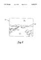
- FIG. 5is a diagram of a video display screen showing the user's view while in replay mode (student path--eye view) through the lane change course generally indicated at 142.
- a similar screen displaycan be seen for replay of the ideal path.
- the viewis at a section line marked 5--5 in FIG. 4b.
- Replay modereplays the path just driven by the student, if replay student path is chosen, or by the instructor, if replay ideal path is chosen, to provide an ⁇ instant replay ⁇ capability.
- the steering wheel 112(FIG. 1) is turned by a motor (not shown) in response to signals from the computer 114 corresponding to the steering wheel position when the path was originally recorded.
- Replay of the ideal pathwill, therefore, give the student the feel of when and how much the steering wheel 112 should be turned to navigate through the course.
- replay of the student's pathgives feedback to the student of what went wrong.
- the view seen by the user 102 during replay modeis similar to the view as originally seen by the user 102 when the course was initially driven.
- the view shown in FIG. 5includes the set of cones 166 (FIG. 4b), the city skyline 144 in the distance and the sky 146. Also shown is a velocity information box 196 containing car velocity, corresponding to the area 188 in FIG. 4b, and an acceleration/braking indication box 198, which contains either the word "THROTTLE” or "BRAKE", corresponding to the area 186 in FIG. 4b.
- FIG. 6is a diagram of a video display screen showing a top plan view or ⁇ bird's-eye ⁇ view of the student's path through the lane change course 142 during replay mode.
- the top view replayis presently only used for the student's path, not the ideal path.
- a simulated car 200is shown such that a "camera” is pointing downward from a point about two hundred feet above the car 200 and in line with the course.
- Two sets of cones 160 and 162are shown in FIG. 6 with the car 200 leaving the set 160 and approaching set 162.
- the information box 196is as described in conjunction with FIG. 5.
- the velocity displayedis 13 mph, and neither the gas pedal 108 nor the brake pedal 106 was depressed so, therefore, the box 198 is not displayed.
- the steering wheel 112(FIG. 1) is turned by a motor (not shown) in response to signals from the computer 114 corresponding to the steering wheel position when the path was originally recorded.
- the student 102(FIG. 1) is provided with a means of self-improvement which is called recursive training. That is, after each pass through a particular course, the student 102 tries to improve on his previous pass in comparison to the ideal path.
- recursive trainingThere are multiple parameters of performance in the presently preferred driver training system 100.
- the student 102may work on a single parameter or choose to work on a multiplicity of parameters, such as braking distances, centering the vehicle on the road, and so forth.
- the route through the simulated environmentmay include different courses or tracks.
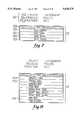
- FIGS. 7, 8, 9, 10, and 11illustrate various menu video screen displays that the user 102 will encounter while using the system 100 (FIG. 1).
- FIGS. 7-10all have a common header area 220.
- the header area 220shows current selections for a track line 220a, a vehicle line 220b, and a weather line 220c.
- the current trackis the judgement track
- the current vehicleis a police cruiser
- the current weatheris day.
- the header area 220will be updated by the computer 114 to reflect the choice.
- a shaded line 222a at the top of a menu box 222identifies the particular menu.
- a cursor rocker switch 113(FIG.
- FIG. 8illustrates a track menu box 230.
- Judgement track, line 230a, and steering track, line 230bare the two tracks having cone courses wherein recording of parameter values is done, summary evaluation screens can be displayed, and replay mode can be executed.
- the other tracksare for different training purposes. For example, the pursuit tracks facilitate training in pursuit of another simulated vehicle.
- the main menu line 230callows return to the main menu 222 (FIG. 7).
- FIG. 9illustrates a vehicle menu box 236.
- four different types of vehiclesi.e., police cruiser, sport sedan, coupe, and roadster, are presented for selection.
- Each vehiclehas different performance characteristics which are stored in the computer 114 (FIG. 1) and utilized by the model process 116 to emulate the selected vehicle. In other embodiments, different and/or additional choices could be provided for selection.
- FIG. 10illustrates a weather or atmospheric effects menu box 240.
- this menuincludes time-of-day conditions, i.e., day, night, dawn, and dusk, in addition to the weather conditions of fog and snow.
- An atmospheric effects functionis performed by the computer 114 (FIG. 1) to emulate the desired weather condition. In other embodiments, different and/or additional choices could be provided for selection.
- FIG. 11illustrates an instruction options menu box 244 that is shown on the video display 122 (FIG. 1) when the user in on one of the two cones tracks, i.e., steering or judgement tracks, and the abort/select switch 111 is pressed down (select).
- the eight choices of the preferred embodimentwill be given hereinbelow. In other embodiments, different and/or additional choices could be provided for selection.
- FIG. 12illustrates the flow diagram for the top-level function of the control process 120 (FIG. 1) called "executive -- control".
- the control process 120is written in the "C” language and cross-compiled using a Green Hills Software, Inc. "C” compiler available from Oasys, a division of Xel, Inc. of Waltham, Mass.
- the control process 120is then executed on a Motorola 68000 microprocessor located in the computer 114.
- a Motorola 68000 microprocessorlocated in the computer 114.
- computerswill recognize that many other computer languages and computers, including pluralities of each, may be used to achieve the same result.
- the presently preferred computer 114includes the general purpose microprocessor (e.g., Motorola 68000), the DSP, the ADSP, and the GSP.
- the presently preferred computer 114also includes read-only memory (ROM) comprising: 128 kilobytes of storage for self-test; 128 kilobytes of storage for ADSP and GSP programs; 81 kilobytes of storage for the DSP program; 256 kilobytes of storage for the 68000 program and tables to define the simulated world; 384 kilobytes of storage for compressed picture data of horizon and hood of the car objects; 256 kilobytes of storage for simulated traffic data; and 192 kilobytes of storage for polygonal objects.
- ROMread-only memory
- the presently preferred computer 114also incorporates random access memory (RAM) for each processor as follows: 68000--about one Megabyte; DSP--64 kilobytes; ADSP--12 kilobytes of program memory (for the program downloaded from the ROM), 16 kilobytes of data memory and 8 kilobytes of buffer memory; and GSP--45 kilobytes of program memory (for the program downloaded from the ROM) and 640 kilobytes of display memory.
- the GSPemploys video random access memory (VRAM) for improved video display rates.
- VRAMvideo random access memory
- the user 102presses up on the abort/select rocker switch 111.
- the computer 114(FIG. 1) directs the video display 122 to display the main menu (FIG. 7) from which the user 102 may choose to select a track from the track menu (FIG. 8), a vehicle from the vehicle menu (FIG. 9), and a weather condition from the weather menu (FIG. 10).
- the usermay choose to change one, two, three, or none of the main menu selections. If no changes are made, the default selections will be used, which include: track--judgement, vehicle--police cruiser, weather--day. After selections are made for track, vehicle, and weather, if desired, or the default choices are accepted, the user selects the ⁇ start scenario ⁇ option and presses the abort/select rocker switch 111 down.
- the computer 114(FIG. 1) initializes observer car (the simulation vehicle) recording. Several initialization steps are performed in the function 274 as will be described following the description for the "executive -- control" function.
- the computer 114(FIG. 1) then moves to the beginning 276 of a loop 277 which only terminates when the abort/select switch 111 is pressed up (abort) or the user 102 has crashed.
- the loop 277is preferably completed at least five times per second so that position information can be displayed in real-time providing the observer car and environment with fluid movement.
- the position of the observer caris obtained from the model process 116 (FIG. 1).
- the model process 116calculates the last position of the observer car based upon the user's inputs which occur asynchronously.
- the computer 114generates the sounds that are appropriate for the observer car, for example, skidding sounds if the observer car is losing traction on the course 142 (FIG. 2).
- a cone courseis any course on either the steering track 140 or the judgement track. If a cone course has been selected, the computer 114 moves on to a "cones" function 284 wherein the user 102 is given choices on performance feedback. If a cone course was not chosen as determined by state 282, the computer 114 proceeds to state 286.
- the recorded position of the pursuit caris updated. This means that the pursuit car is placed in a certain position in the graphical universe or environment 139 (FIG. 2) prior to the display system of the computer 114 (FIG. 1) actually updating the video display 122.
- the recorded position of the observer caris updated. The observer car is placed in a certain position in the graphical universe 139.
- the computer 114checks to see whether the abort/select rocker switch 111 has been pressed up (abort) or the simulated vehicle has crashed.
- a display commandis initiated to the digital signal processor (not shown) in the computer 114 (FIG. 1), such as the ADSP-2101 chip available from Analog Devices of Norwood, Mass.
- the digital signal processornot shown
- display objectssuch as the track, background, pursuit car (if on a pursuit track), and observer car, are appropriately translated in the graphical universe 139 (FIG. 2) according to the perspective of the user 102, for later display on the video display 122.
- Included in this function 292is a call to an "atmospheric -- effects" function 520 (FIG. 21 described hereinbelow) to accurately simulate the track and background in various time-of-day and weather conditions.
- the instrument panel 130including the speedometer, turn signal indicators, and various indicator lights, is updated.
- a separate fuel gauge(not shown) is also updated.
- collision soundsare generated. These are the sounds associated with the observer car colliding with barriers, cones, buildings, and the like.
- the video display 122has its three-dimensional graphics display updated by a command being issued to the graphics signal processor such as, for example, the 34010 chip distributed by Texas Instruments, which can handle color filled three-dimensional graphics in real-time.
- the loop 277is completed by returning to state 276 to begin the next pass of the loop.
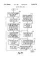
- FIG. 13there is illustrated the flow diagram for the "init -- precord" function 274 shown in FIG. 12.
- the computer 114moves to a state 310 wherein the graphical universe or environment 139 (FIG. 2) is initialized based on the selections made at state 272 (FIG. 12) for track and weather.
- the computer 114then moves to a state 312 to create the graphical object called the observer car.
- the observer car objectis created to be used in the student's top view replay function.
- the position of the observer car objectis set to the edge of the universe so that it is not seen on the video display 122 (until replay time, for example).
- the function 274then returns to the "executive -- control" function at a return state 316.
- the computer 114moves to a decision state 330 wherein it is determined whether the abort/select switch 111 has been pressed down (select). If so, the computer 114 (FIG. 1) moves to a state 332 and displays the instruction options menu (FIG. 11) on the video display 122.
- the computer 114then checks for which option of the instruction options menu is selected by the user 102 (FIG. 1) in states 334 to 354. If summary evaluation is determined to be selected at a decision state 334, the computer 114 calls the "summary -- evaluation" function 336. If not, the computer 114 checks if replay ideal path is determined to be selected at a decision state 338 and if so, the computer calls the "replay -- ideal -- path” function 340. If not, the computer 114 checks if replay student--eye view is determined to be selected at a decision state 342 and if so, the computer calls the "replay -- student -- eye -- view" function 344.
- the computer 114checks if replay student--top view is determined to be selected at a decision state 346 and if so, the computer calls the "replay -- student -- top -- view” function 348. If not, the computer 114 checks if save ideal path is determined to be selected at a decision state 350 and if so, the computer calls the "save -- ideal -- path" function 352.
- the computer 114checks if replay speed is determined to be selected at a decision state 354 and if so, the computer 114 allows the user 102 (FIG. 1) to select a replay speed.
- the replay speedchanges from full speed (1/1) to 1/2 speed to 1/4 speed to 1/8 speed and then back to full speed in a circular queue manner by pressing down on the abort/select switch 111 (select).
- the selected replay speedis saved in the global variable ⁇ replay -- slowmo ⁇ .
- the computer 114then calls the "replay -- speed" function 356.
- the computer 114checks to see if the user 102 desires to change the state of the auto enable/disable flag. If so, the flag is toggled to the opposite state and the computer 114 moves to state 360. If not, the user 102 (FIG. 1) has selected the exit choice of the instruction options menu and the computer 114 proceeds to state 360. The computer also proceeds to state 360 after completion of any of the functions 336, 340, 344, 348, 352, or 356.
- the computer 114determines if the car is stopped and the brake pedal 106 is depressed.
- a feature of the driver training system 100is that the computer 114 will not automatically move from a display of the simulated graphical universe 139 (FIG. 2) wherein the user 102 is driving a car to a performance evaluation display such as the summary evaluation unless the conditions of state 360 are true. These conditions help prevent the user 102 from having a feeling of rapid change of environment and confusion.
- the computer 114moves to a decision state 362 to determine if the auto enable/disable flag is set to the enable state. If so, the computer 114 displays the course at state 364 by calling the "summary -- evaluation" function 336.
- Both the ideal path and the student's pathare displayed.
- the computer 114uses the previously run course as the student's path if it is available, i.e., it has not been purged as described in state 370 below and at least one course has been driven, and if a course is not currently selected, e.g., the car is stopped before the white cones rectangle 152 (FIG. 3) of a particular course. Otherwise, the computer will use the currently selected course for the student's path.
- the system 100is preloaded with ideal path data for each cone course. Therefore, at least the ideal path will be displayed by state 364. Following the completion of state 364, the computer 114 advances to state 360.
- the computer 114(FIG. 1) proceeds to state 366 and determines if the simulated car has entered the area between the two rows of white cones of rectangle 152 (FIG. 3) for any of the five possible cone courses. If so, the current course is changed to that associated with the white cone area just entered by the simulated car. Next, the computer 114 purges or clears the save -- point buffer.
- the save -- point buffer(described below) is an area of memory assigned to record the data associated with the course currently being driven. The data from the previously driven course is retained in this buffer until it is purged at state 370.
- the computer 114moves to a decision state 372.
- the computerdetermines if the car is inside the record rectangle 154 (FIG. 3) of the selected course. If so, the computer 114 records the following set of data in the presently preferred embodiment at 1/5 second intervals, known as delta time, at state 374 and saves the data in the save -- point buffer at state 376: (1) position of the car in three dimensional space; (2) orientation of the car in three dimensional space; (3) time associated with each data point interval; (4) position of steering wheel 112 (FIG.
- the computer 114moves to state 390 wherein the course for which this function 336 is to be performed is identified.
- the coursewill either be the current course, as determined by state 368 (FIG. 14) or the course associated with state 364 (FIG. 14).
- the computer 114scans an object database for cones within the evaluation rectangle 156 (FIG. 3) of the selected course.
- the computer 114plots both regular (standing) cones and knocked-over or hit cones in a top view format on the video display 122 (FIG. 1) as shown in FIG. 4b.
- the data in the save -- point buffercan be saved in a portion of an ideal -- path buffer.
- the ideal -- path bufferhas a section for each of the five cone courses.
- the ideal path data that is preloaded for each cone courseis stored in the ideal -- path buffer but can be overwritten as selected by the user 102 (FIG. 1).
- datais retrieved from the ideal -- path buffer for the selected course and from the save -- point buffer (if available) for each delta time interval recorded at state 374 (FIG. 14).
- the following parameter valuesare retrieved for this function 336: position of steering wheel 112 (FIG. 1), position of car, velocity, status of brake pedal 106, and status of gas pedal 108.
- the retrieved valuesare then plotted at state 398 by the computer 114 on the video display 122 as shown by the example of FIG. 4b.
- the displayhas an implied distance scale that is proportional to the course length, thus, a longer course means a more condensed display. Only data points within the evaluation rectangle 156 are plotted.
- the velocity valuesare displayed at intervals determined by the computer 114 such that the display is easy to read.
- the computerUpon completion of state 398, the computer returns at state 400 to the "cones" function 284 of FIG. 14.
- This function 340performs an ⁇ instant-replay ⁇ feature of the ideal path from a viewpoint inside the car, along with controlling the steering wheel 112 (FIG. 1) to emulate the motions of the wheel 112 when the course was initially recorded.
- the computer 114determines if the real-time value equals a delta time value of a recorded data point. For example, if the real-time value is 3/5 second after time zero, a delta time interval would match (three times 1/5 second) and the computer 114 proceeds to state 414.
- the computer 114retrieves the data associated with the delta time interval of a recorded data point in the ideal -- path buffer for the selected course.
- the data retrieved for this function 340includes: the position of the car, the orientation of the car, and the position of the steering wheel.
- the retrieved valuesare then captured at state 416 in a global variable ⁇ camodb ⁇ (camera object database).
- the loop of function 340is executed approximately ten to thirty times per second. Because data is recorded at 1/5 second intervals, if a full speed replay is desired, interpolation between data points must be done. (Replay speeds of 1/2, 1/4, or 1/8 normal speed replay are available as will be described below.) At full speed, therefore, approximately 5 to 25 interpolations must be done.
- the computer 114(FIG. 1) moves to state 418.
- the computerdoes a linear interpolation between the two nearest recorded data values, as determined by the real-time clock value, for the following parameters: the position of the car, the orientation of the car, and the position of the steering wheel.
- the newly created valuesare then captured at state 420 in the global variable ⁇ camodb ⁇ .
- the computer 114moves to state 422 and updates a global variable ⁇ replay -- force ⁇ with the data for the position of the steering wheel 112 (FIG. 1) from the results of state 414 or 418.
- Replay -- forceis used at state 424 by a steering process to asynchronously force a steering controller of the steering wheel 112 through an Interrupt Service Routine (ISR).
- ISRInterrupt Service Routine
- the computer 114executes "display -- objects" function 292 wherein a display command is initiated to the ADSP.
- Display objectssuch as the track, and background, are appropriately translated in the graphical universe 139 (FIG. 2) according to the perspective of the user 102, for later display on the video display 122 (FIG. 1).
- Included in this function 292is a call to the "atmospheric -- effects" function 520 (FIG. 21) to accurately simulate the track and background in various time-of-day and weather conditions.
- the video display 122has its three-dimensional graphics display updated by a command issued to the GSP.
- the computer 114then moves to a decision state 430 and determines if there are more data points in the ideal -- path buffer for the selected course. If so, the computer 114 loops back to the decision state 412 where a new value of the real-time clock is checked. When all data points in the ideal -- path buffer for the selected course have been used at state 430, the computer 114 returns at state 432 to the "cones" function of FIG. 14.
- the "replay -- student -- eye -- view” function 344 shown in FIG. 14is very similar to the "replay -- ideal -- path” function 340 just described. The difference is that the data is retrieved from the save -- point buffer rather than the ideal -- path buffer.
- This function 348performs an ⁇ instant-replay ⁇ feature of the student's path from a simulated viewpoint two hundred (200) feet above the car, along with controlling the steering wheel 112 (FIG. 1) to emulate the motions of the wheel 112 when the course was initially recorded.
- This function 348is similar to the "replay -- ideal -- path function" 340 and, therefore, only the states different from those in function 340 will be described.
- States 440 and 442perform the same task as states 410 and 412 of function 340 (FIG. 16).
- States 444 and 448are similar to states 414 and 418 of function 340 except that the data is retrieved from the save -- point buffer in function 348 rather than the ideal -- path buffer in function 340.
- States 446 and 450are similar to states 416 and 420 of function 340 except that the values for the position and orientation of the car are saved in a global variable ⁇ my -- object ⁇ in function 348 rather than the global variable ⁇ camodb ⁇ in function 340.
- States 452 and 454perform the same task as states 422 and 424 of function 340.
- the major difference between the two functions 340 (FIG. 16) and 348is at state 456 of function 348 wherein the view seen on the video display 122 (FIG. 1) is changed from inside the simulated car looking forward to an overhead view looking down at the car and moving with the car.
- the camerais set to be at an apparent height of two hundred (200) feet above the simulated car and oriented to look downward and in line with the course.
- the cameramoves with the car to produce a view that is directly over the car as the car moves through the course.
- the new camera view values from state 456are captured in the global variable ⁇ camodb ⁇ .
- the objects displayed from a ⁇ bird's-eye ⁇ perspectiveinclude the track and a representation of the observer car.
- the observer caris only displayed in the "replay -- student -- top -- view” function 348.
- States 462performs the same task as state 428 of function 340.
- Decision state 464is similar to decision state 430 of function 340 except that the buffer checked is the save -- point buffer at state 464 rather than the ideal -- path buffer at state 430.
- the computer 114then returns to the "cones" function 284.
- the "save -- ideal -- path" function 352 shown in the "cones” function of FIG. 14will be described.
- This function 352saves the data associated with the course that was just driven as the new ideal path for that course.
- the computer 114moves to state 470 wherein the data in the save -- point buffer is retrieved.
- state 472the computer 114 copies the retrieved data into the ideal -- path buffer corresponding to the course for which the data was recorded.
- the computer 114returns to the "cones" function 284 (FIG. 14).
- the "replay -- speed” function 356 shown in the "cones” function of FIG. 14will be described.
- This function 356sets up a subsequent call to one of the replay functions, but with a slow-down factor such that the replay is slow enough for the user 102 (FIG. 1) to observe and learn more.
- the function 356itself does not start a replay.
- the computer 114moves to state 480 wherein the global variable ⁇ replay -- slowmo ⁇ , described in conjunction with the "cones" function (FIG. 14), is retrieved.
- the computer 114determines if the replay speed selected is 1/2. If so, the delta time is multiplied by two.
- the computer 114proceeds to state 486 to determine if the selected speed is 1/4. If so, the delta time is multiplied by four. The delta time interval becomes 4/5 second, and five actual data points will be available per each four seconds of replay time. If the replay speed selected is not 1/4 as determined at decision state 486, the computer 114 proceeds to state 490 to determine if the selected speed is 1/8. If so, the delta time is multiplied by eight. The delta time interval becomes 8/5 second, and five actual data points will be available per each eight seconds of replay time. If the replay speed selected is not 1/8 as determined at decision state 482, the implied speed is full speed, and therefore, delta time is not multiplied. The computer 114 (FIG. 1) proceeds to state 494 and returns to the "cones" function 284 (FIG. 14).
- FIG. 20ais a diagram of a video display screen showing a view as the user 102 (FIG. 1) approaches a mountain range 502 along a simulated roadway 504.
- FIG. 20aalso shows a sky 508 and a ground 509.
- FIG. 20bshows the same view as FIG. 20a, but with a layer of haze 506.
- the haze 506could be the result of fog, smog, smoke, or any other similar atmospheric condition.
- the haze 506is of a thickness that the mountain range 502 in the background is partially visible. This condition may represent dusk or dawn.
- the condition simulatedis fog 506', wherein the hazing is so thick as to obscure the background mountain range 502' (FIG. 20b).
- the user 102FIG. 1
- the haze 506'lightens and gradually the object (in FIG. 20c) changes colors due to the optical distortion caused by particles in the air reflecting and blocking light.
- a sequence similar to that of the previous sentenceoccurs for the mountain range 502 (in FIG. 20b).
- FIG. 20cbrightness is affected by haze.
- a first building 510is more distinct and brighter than a second building 512 that is at a greater distance from the position of the simulated car.
- FIGS. 20a,b,conly demonstrate the effect of hazing in the horizontal dimension while hazing in the vertical dimension, though not shown, is also included in the present invention.
- the haze 506distorts colors according to the type of atmospheric condition being simulated.
- the following conditions and color tonesare displayed in the graphical universe 139: night--black, fog--grey, dusk--violets, dawn--yellows, day--standard or default colors, and snow--white.
- sky 508 and ground 509are treated differently from other objects in the graphical universe 139.
- the types of atmospheric conditions or hazes available to the user 102(FIG. 1) will be preselected by an animator.
- six conditionsare presently provided and are selectable by the user 102. These conditions are shown in FIG. 10 as a menu display of the driver training system 100. So that processing time is conserved by the computer 114 (FIG. 1), certain other assumptions of the present embodiment are that the haze 506 has a uniform consistency, and that all points of a polygon are treated as the same color even though individual points may be different distances from the viewpoint or camera position looking into the graphical universe 139.
- FIG. 21shows a flowchart of a portion of the approximation of atmospheric conditions or "atmospheric -- effects” function 520 of the present invention.
- the function 520is called by the "display -- objects" function 292 of the "executive -- control" function 120 (FIG. 12), the “replay -- ideal -- path” function 340 (FIG. 16), and the “replay -- student -- top -- view” function 348 (FIG. 17).
- the "atmospheric -- effects" function 520is not embodied in any one function in the control process 120 (FIG. 1) but instead is distributed among various states and functions of the control process 120.
- the flow diagram of FIG. 21is only a logical representation of a collection of functions.
- the attached Microfiche Appendixhas the associated computer source code with the following titles: dither.c; dithadsp.doc; and dithgsp.doc.
- the source codeis executed by the 68000 microprocessor, the ADSP, and the GSP, respectively.
- the "atmospheric -- effects" function 520makes the following changes to parameters, or characteristics, of the graphical universe 139 (FIG. 20a): (1) sky color--a function of thickness of the haze; (2) ground color--similar to sky color; (3) dimval--a preselected parameter that determines the minimum distance before the haze begins to affect colors; (4) kval--a preselected parameter that determines how quickly colors change in haze; (5) sun1, sun2--preselected positions and intensities of two light sources; and (6) color palettes--preselected hues and intensities associated with each polygon that determine how colors change in haze.
- the sky and ground colorsare changed dynamically at state 546 of function 520.
- the remaining above-listed parametersare set in the initialize universe states 522 and 524.
- the multiple light sources, or suns(sun1 and sun2), are used to provide greater depth to the polygonal images. For instance, in the case of a single sun, if an object of uniform color faces the user and there is a corner where two faces meet, both faces would appear to have the same color and thus would appear joined in a flat plane. However, if one sun is directing 90% of the total light intensity at a first angle and the other sun is directing 10% of the total light intensity from a second angle, then one face of the object has a slightly different shade of color than the other. Resolving the issue of depth becomes especially important when there is a limited number of colors to choose from in any given palette, which will likely be the case for most common video systems.
- every polygonis given a color palette by an animator.
- a 15 color paletteranging from 0 to 14 is used for each polygon.
- This paletteis arranged into regions of different shading and hazing values.
- the first 8 colors in the palette, 0 through 7contain linear shading steps from the natural color of the polygon to the fully shaded color with 0% hazing and colors 8 through 11 contain linear shading steps with 25% hazing.
- the palettecontains the base color of the polygon modified by a haze and shade percentage. The parameters kval and dimval are then chosen to reflect the thickness and type of haze.
- the "atmospheric -- effects" function 520is entered at a start state and proceeds to a state 522 wherein the "atmospheric -- effects” function 520 sets one sun vector equal to the camera vector (i.e., both unit vectors now point in the direction in which the camera is pointed) and the other sun vector is directed downward.
- the vector copyis necessary to force the sun to come from the user's perspective since light is assumed to scatter in all directions anyway.
- the color paletteis configured to reflect current hazing conditions. As first initiated by the control process 120, the remaining set of states relating to the coloring and display of polygons other than sky and ground are performed by the ADSP and GSP of the computer 114 (FIG. 1).
- the "atmospheric -- effects" function 520begins the set of states that will select colors for polygons according to the preselected thickness of haze as determined by dimval and kval.
- the "atmospheric -- effects" function 520selects a polygon for coloring.
- objects in the graphical universe 139e.g., buildings or signs, are formed from polygons. It is polygons from these objects which are selected for coloring.
- the "atmospheric -- effects" function 520moves to the state 530 wherein the function 520 calculates the distance z, between the camera and the selected polygon.
- the farthest vertex of the polygonis chosen as the polygon reference point for the distance z, but any point on the polygon could be chosen.
- State 530then calculates the haze value from the distance z as follows:
- zis the distance between the camera position and the polygon
- kvalis a constant; and dimval is the distance for full hazing.
- kvalis preferably set to the haze range. In an integer application, however, kval is chosen so as to provide sufficient range to cover the entire haze range.
- the function 520compares z and dimval. If z is greater than dimval, the polygon is completely obscured by the haze and no further processing (dithering) is performed for this polygon. The function 520 continues to a decision state 544 to check if more polygons exist. If, however, z is less than dimval, the polygon is partially visible through the haze and function 520 moves to state 534.
- Each dot productis a scaler having a magnitude depending on the angle subtended between the two vectors and the magnitude of the sun vector. Thus, if two vectors are perpendicular, their dot product will be zero, indicating one-half intensity of the polygon color.
- state 534sums the components of the dot products (in the present embodiment there are two suns, sun1 and sun2).
- each sun vectorhas a magnitude (intensity) that is equal to 1.0 so that, assuming that the suns are pointing in the same direction, the maximum possible range before scaling is (-2.0,2.0). After scaling, the range is scaled so that the magnitude of A will always be (0,4.0).
- the "atmospheric -- effects" function 520then proceeds to state 536 where the colors of the dither pattern for the polygon are determined.
- the dither colorsare defined in a dither lookup table that is indexed by haze value and shade value. Each entry in the dither lookup table contains offsets into the polygon palette for the two colors, X0 and X1, to be used in the dither pattern. In the present embodiment, each polygon uses 16 colors in the palette for each polygon; thus, X0 and X1 have values between 0 and 15.
- the "atmospheric -- effects" function 520the proceeds to state 538 where the offsets for the two dither colors are added to the base color.
- the base color, B, of a polygonspecifies which group of 16 colors to use. In a palette of 256 colors, there is a possibility of 16 groups of colors to choose from. Thus the base color for a polygon is in the range 0 to 15.
- the two dither colors for a polygon, C0 and C1are determined as follows:
- state 540determines the dither pattern based on the position of the polygon.
- the dither pattern employed in the present embodimentuses a 2-color 2 ⁇ 2 dither pattern arranged in an "X" pattern as follows:
- state 540selects pattern 1 if the polygon starts on an even scan line and pattern 2 if on an odd scan line.
- the control process 120(FIG. 1), employing the GSP, draws the polygon on the video display 122 as shown at state 542 using the dither pattern calculated in state 540.
- the ADSPdetermines whether there are more object polygons to color and display at state 544. If there are more polygons, then the "atmospheric -- effects" function 520 continues by moving to loop state 526. Otherwise, if all object polygons have been drawn, then the function 520 proceeds to state 546.
- the function 520sets the colors palettes for the sky 508 (FIG. 20a) and ground 509.
- the colors of the sky 508are chosen such that they sky is the color of the haze, e.g., gray for fog and black for night.
- the color paletteis changed according to the color and density of the haze.
- the ground 509(FIG. 20a) consists of many polygons, each corresponding to a given distance from the camera. As the camera moves closer to these polygons, they gradually appear out of the haze.
- a set of fifteen colorsare presently preferred ranging between colors 0 and 14 as follows: color 14--the color of a polygon beyond the range of maximum visibility and color 0--the color of a polygon without any atmospheric discoloration.
- the horizonis segmented into fifteen polygons. The larger the number of colors and polygons the better the approximation. However, as these numbers increase, the computation becomes more complex. Hazing of the horizon image is performed to match the current dimming distance (dimval).
- the hazing conditionsare set for fog with a 140 ft. visibility.
- Each polygonis spaced 10 ft. apart (140 ft./14) with polygon 0 being 0 ft. from a camera located at the lowest point of the ground 509 and polygon 14 being 140 ft. from the same camera position. Then assume that the vehicle has driven to the top of a 50 ft. rise. Thus, polygon 0 is 50 ft. from the camera, polygon 1 is 60 ft. from the camera, and so on.
- polygon 0for example, the "atmospheric -- effects" function 520 takes the distance between the polygon and the camera, 50 ft., and linearly interpolates between the colors of the original range. For example, to set the colors of the color palette associated with the ground 509, polygon 0 would be 50/140 (35.7%) between the ground color and the fog color, polygon 1 would be 60/140 (42.8%), etc. Polygons more distant then the visibility distance, 140 ft. in this example, would be obscured by the fog and be 100% fog color.
- Changing the maximum visibilitymeans that the distance between the polygons is different. For example, if the visibility is 350 ft., then each polygon is spaced 25 ft. apart (350 ft./14). With the vehicle at the top of a 50 ft. rise, polygon 1 would then be the color 75/350 (21.4%) between ground color and fog color.
- the instrument panel 130 of the system 100includes a speedometer 602, a transmission gear indicator display area 604, a transmission gear indicator 606, a indicator and warning light area 608.
- Several input devices of the system 100including the turn signal lever 104, the automatic transmission or shift lever 110, and the steering wheel 112, are also shown.
- the speedometer 602 and indicatorsbecome active when the user 102 (FIG. 1) "starts” the simulated vehicle.
- the speedometer 602provides a measurement of velocity.
- the gear indicator 606visually displays the position of the shift lever 110 upon the gear indicator display area 604.
- the indicator and warning light area 608includes the following designators (left to right): left turn signal 608a, temperature, battery, seat belt, brake (shown as a box on FIG. 22), oil pressure, high beam (headlights), emergency flasher, and right turn signal 608b.
- the turn signal lever 104mounted on a steering column housing 610.
- the assembly 612is contained within the housing 610.
- the lever 104has three positions: a center or neutral position indicated by the solid lines, a right turn position 104' indicated by the dashed lines, and a left turn position (not shown).
- a center or neutral positionindicated by the solid lines
- a right turn position 104'indicated by the dashed lines
- a left turn position(not shown).
- the center positionis the position of the steering wheel 112 when the simulated car is moving in a straight-ahead path.
- the assembly 612maintains the active state of the right turn signal 608b into the turn.
- the steering wheel 112is turned in a counterclockwise direction. While the steering wheel 112 is returning toward the center position, the lever 104 returns to the center position and the right turn signal 608b shuts off.
- the turn signal lever 104is held by a retainer plate 614 mounted on a frame 618, which turn about a pivot point 616.
- a right turn plunger 619is mounted in a bore in the frame 618 and is held in position by a spring (not shown) in the bore.
- a center detent 620, a right detent 621 (dashed lines), and a left detent 622are shown on the retainer plate 614. The right and left detents are used to hold the position of the lever 104 from the center detent position.
- a right turn microswitch 624connects to the computer 114 (FIG. 1) via signal wires (not shown).
- the lever 104When the lever 104 is pressed upward to a position 104', the frame 618 rotates clockwise around the pivot point 616 and depresses a micro-plunger of the microswitch 624 until a hard stop 626 is reached. New right turn positions of the frame 618' and the plunger 619' are indicated by dashed lines.
- the turn signal lever 104is held at the position 104' by the right detent 621.
- the microswitch. 624sends a signal to inform the control process 120 (FIG. 1) that a right turn is taking place.
- the control process 120then sends a signal to the instrument panel 130 (FIG. 1) activating the right turn signal 608b (FIG. 22).
- a cancel pin 630also turns with the steering wheel in a hub area 632.
- a rotation 634 of the cancel pin 630moves the plunger 619 in the bore against the spring, but does not affect the position of the frame 618'.
- the plungerAfter the cancel pin 630 passes by the plunger 619 in its temporary position pressed against the spring, the plunger returns to its dashed line position 619'.
- the cancel pin 630continues its rotation until, for example, a twelve o'clock position is attained at the apex of the right turn.
- a rotation 640causes the cancel pin 630 to press against the side of the plunger 619 at position 619'.
- This pressure on the plunger 619causes the frame 618 to turn counterclockwise about the pivot point 616 which causes the lever 104 to return to the center position.
- the microplunger on the microswitch 624is thereby released to deactivate the right turn signal 608b (FIG. 22) via a signal sent to the computer 114 (FIG. 1).
- a similar microswitch, hard stop, and plunger(not labelled) to those discussed above are symmetrically positioned in the assembly 612 for making a left turn.
- FIG. 24is a side elevational diagram showing a cross section of a seat and low frequency speaker assembly 700.
- the purpose of the assembly 700is to provide the user 102 (FIG. 1) with meaningful and realistic road feel cues.
- the assembly 700includes a housing such as a seat 702 that has at least a portion of its interior hollow with a recess 706 of the seat 702 having the low frequency speaker 128 (FIG. 1) mounted and secured such that a diaphragm of the speaker 128 is in communication with the air that is enclosed in the envelope or bladder 704 of the seat.
- the diaphragmmoves back and forth in a conventional manner in response to a signal presented at the speaker terminals. This back and forth motion is communicated through the air creating vibration on the surfaces 708 of the seat 702.
- the surfaces 708are made of a somewhat flexible but strong plastic material.
- the back and bottom surfacesare somewhat thicker and hence stiffer, while the surfaces in contact with the user 102 (FIG. 1) are thinner to flex in response to the vibration of the air.
- the surfaces in contact with the user 102may be overlaid by a cover 709.
- the speaker 128 of the presently preferred embodimentis a model 40-1348 dual-coil eight inch speaker sold by Radio Shack.
- the speaker 128has four terminals, a first set of terminals 710 is visible in FIG. 24.
- the speaker 128is fastened to the seat 702 by four bolts, the locations of two are indicated by a pair of holes 712a and 712b.
- the speaker 128is connected to the control process 120 (FIG. 1) of the system 100 through the low pass filter 126 and the amplifier 127.
- the filter and amplifierare both manufactured by Atari Games Corporation.
- the model number of the amplifieris 044431-03.
- the control process 114sends signals representative of, for example, collisions with objects, engine noise, and so forth, to the low frequency filter 126.
- the filter 126has a frequency cutoff at 350 Hertz (Hz). Therefore, only signals with a frequency content below 350 Hz will be sent to the amplifier 127 from the filter 126.
- the control process 120retrieves a wave sample of the sound from a wave table (not shown) and sends this signal, having a sharp low frequency peak, to the filter 126.
- the filterpasses the low frequency content (below 350 Hz) of the signal to the amplifier 127.
- the amplifier 127which can produce a 28 volt peak-to-peak output signal at maximum gain, increases the amplitude of the signal. This high amplitude signal is then sent to the speaker 128.
- the speaker 128communicates a high excursion pulse through the diaphragm to the envelope 704 of the seat 702 and ultimately to the user 102 sitting on the seat surfaces 708. The user 102 will experience a quick jolt to simulate the feel of hitting the cone as the speaker diaphragm moves the air in the seat envelope 704.
- the control process 120accesses different samples of sounds stored in the wave table.
- the signals, created by the playback of the sound by the control process 120have varying frequency content, amplitude, and duration.
- the signal created by the control process 120 for a cone collisionmay have a duration in the range of 100 milliseconds to one second.
- Other signals, such as for engine noisesmay run for five seconds or more, depending on the rate of acceleration or deceleration.
Landscapes
- Engineering & Computer Science (AREA)
- Theoretical Computer Science (AREA)
- Multimedia (AREA)
- Physics & Mathematics (AREA)
- General Physics & Mathematics (AREA)
- Computer Graphics (AREA)
- Aviation & Aerospace Engineering (AREA)
- Business, Economics & Management (AREA)
- Educational Administration (AREA)
- Educational Technology (AREA)
- Human Computer Interaction (AREA)
- Processing Or Creating Images (AREA)
Abstract
Description
haze value=(z*kval)/dimval
haze value=(z*kval)/dimval
______________________________________pattern 1 ORpattern 2 ______________________________________ C0 C1 C1 C0 C1 C0 C0 C1 ______________________________________
Claims (35)
Priority Applications (1)
| Application Number | Priority Date | Filing Date | Title |
|---|---|---|---|
| US08/339,478US5618179A (en) | 1992-05-22 | 1994-11-14 | Driver training system and method with performance data feedback |
Applications Claiming Priority (2)
| Application Number | Priority Date | Filing Date | Title |
|---|---|---|---|
| US07/888,375US5366376A (en) | 1992-05-22 | 1992-05-22 | Driver training system and method with performance data feedback |
| US08/339,478US5618179A (en) | 1992-05-22 | 1994-11-14 | Driver training system and method with performance data feedback |
Related Parent Applications (1)
| Application Number | Title | Priority Date | Filing Date |
|---|---|---|---|
| US07/888,375ContinuationUS5366376A (en) | 1992-05-22 | 1992-05-22 | Driver training system and method with performance data feedback |
Publications (1)
| Publication Number | Publication Date |
|---|---|
| US5618179Atrue US5618179A (en) | 1997-04-08 |
Family
ID=25393073
Family Applications (3)
| Application Number | Title | Priority Date | Filing Date |
|---|---|---|---|
| US07/888,375Expired - LifetimeUS5366376A (en) | 1992-05-22 | 1992-05-22 | Driver training system and method with performance data feedback |
| US08/339,478Expired - LifetimeUS5618179A (en) | 1992-05-22 | 1994-11-14 | Driver training system and method with performance data feedback |
| US08/342,711Expired - Fee RelatedUS5573402A (en) | 1992-05-22 | 1994-11-21 | System and method for coloring polygon using dithering |
Family Applications Before (1)
| Application Number | Title | Priority Date | Filing Date |
|---|---|---|---|
| US07/888,375Expired - LifetimeUS5366376A (en) | 1992-05-22 | 1992-05-22 | Driver training system and method with performance data feedback |
Family Applications After (1)
| Application Number | Title | Priority Date | Filing Date |
|---|---|---|---|
| US08/342,711Expired - Fee RelatedUS5573402A (en) | 1992-05-22 | 1994-11-21 | System and method for coloring polygon using dithering |
Country Status (1)
| Country | Link |
|---|---|
| US (3) | US5366376A (en) |
Cited By (85)
| Publication number | Priority date | Publication date | Assignee | Title |
|---|---|---|---|---|
| US5772504A (en)* | 1995-09-12 | 1998-06-30 | Konami Co., Ltd. | Driving game machine |
| US5919045A (en)* | 1996-11-18 | 1999-07-06 | Mariah Vision3 Entertainment Llc | Interactive race car simulator system |
| US5951018A (en)* | 1997-06-13 | 1999-09-14 | Konami Co., Ltd. | Simulative driving game machine |
| US6010403A (en)* | 1997-12-05 | 2000-01-04 | Lbe Technologies, Inc. | System and method for displaying an interactive event |
| ES2144972A1 (en)* | 1998-08-12 | 2000-06-16 | Univ Valencia Politecnica | AUTOMOBILE DRIVING SIMULATOR FOR THE EVALUATION OF DISABLED DRIVERS. |
| KR20000072325A (en)* | 2000-08-29 | 2000-12-05 | 연대성 | advertisement inserting type traveling simulation game method using virtual reality |
| US6168519B1 (en)* | 1998-06-03 | 2001-01-02 | Konami Co., Ltd. | Image display game system, image display method for same, and storage medium storing image display program for same |
| US6171186B1 (en)* | 1996-07-25 | 2001-01-09 | Kabushiki Kaisha Sega Enterprises | Game processing method, game device, image processing device, image processing method, and recording medium |
| KR20010016334A (en)* | 2000-12-04 | 2001-03-05 | 이강우 | The system having effects to provide roads information and knacks for careful driving and to be trained the driving skill |
| US6200138B1 (en)* | 1997-10-30 | 2001-03-13 | Sega Enterprises, Ltd. | Game display method, moving direction indicating method, game apparatus and drive simulating apparatus |
| US6278383B1 (en)* | 1995-04-20 | 2001-08-21 | Hitachi, Ltd. | Map display apparatus |
| US6287201B1 (en)* | 1999-03-12 | 2001-09-11 | Midway Games West | Arcade game with keypad input |
| US6322368B1 (en) | 1998-07-21 | 2001-11-27 | Cy Research, Inc. | Training and testing human judgment of advertising materials |
| FR2813691A1 (en)* | 2000-09-05 | 2002-03-08 | Christian Saunier | TRAINING SIMULATOR FOR THE DRIVING AND IMPLEMENTATION OF AGRICULTURAL MACHINERY |
| US6368217B2 (en)* | 1997-02-14 | 2002-04-09 | Kabushiki Kaisha Sega Enterprises | Input device, data processing device, data processing method, game device and medium |
| US20020052724A1 (en)* | 2000-10-23 | 2002-05-02 | Sheridan Thomas B. | Hybrid vehicle operations simulator |
| US6416412B1 (en)* | 1999-03-16 | 2002-07-09 | Atari Games Corporation | System for remotely activating a sound in a game unit |
| US20020091534A1 (en)* | 2001-01-05 | 2002-07-11 | Berning Carol Kohn | Facility for conducting consumer product research |
| US20020124260A1 (en)* | 2001-03-02 | 2002-09-05 | Creative Design Group, Inc. | Video production system for vehicles |
| US20020156872A1 (en)* | 2001-01-04 | 2002-10-24 | Brown David W. | Systems and methods for transmitting motion control data |
| US20030130822A1 (en)* | 2001-11-28 | 2003-07-10 | Steele Robert C. | Multimedia racing experience system |
| US6612925B1 (en)* | 1998-09-22 | 2003-09-02 | Covepath Limited | Computer game |
| WO2002062436A3 (en)* | 2001-02-06 | 2003-10-16 | Electronic Arts Inc | Integration of real-time data into a gaming application |
| US20040158476A1 (en)* | 2003-02-06 | 2004-08-12 | I-Sim, Llc | Systems and methods for motor vehicle learning management |
| US20040169653A1 (en)* | 1995-04-20 | 2004-09-02 | Yoshinori Endo | Bird's-eye view forming method, map display apparatus and navigation system |
| US20040191730A1 (en)* | 2001-12-17 | 2004-09-30 | Pierre Couder | Computer-assisted learning method and system for real time reproduction of a vehicle reactions |
| US20050091018A1 (en)* | 2003-09-05 | 2005-04-28 | Road Safety International, Inc. | System for combining driving simulators and data acquisition systems and methods of use thereof |
| WO2005076242A1 (en)* | 2004-02-03 | 2005-08-18 | Drag Tag Pty Ltd | Apparatus for simulated driving of a motor vehicle |
| US20050228620A1 (en)* | 2004-04-08 | 2005-10-13 | Corys Training & Engineering Support Systems | Method and apparatus for simulating a train and track |
| US20060040239A1 (en)* | 2004-08-02 | 2006-02-23 | J. J. Keller & Associates, Inc. | Driving simulator having articial intelligence profiles, replay, hazards, and other features |
| EP1029569B1 (en)* | 1999-02-15 | 2006-06-07 | Kabushiki Kaisha Sega doing business as Sega Corporation | Game device |
| US20060206219A1 (en)* | 1995-05-30 | 2006-09-14 | Brown David W | Motion control systems and methods |
| US20060252548A1 (en)* | 2005-05-06 | 2006-11-09 | Nintendo Co., Ltd | Communication game system, game apparatus, server, storage medium storing a program, and game control method |
| US7137107B1 (en) | 2003-04-29 | 2006-11-14 | Roy-G-Biv Corporation | Motion control systems and methods |
| US7139843B1 (en) | 1995-05-30 | 2006-11-21 | Roy-G-Biv Corporation | System and methods for generating and communicating motion data through a distributed network |
| US20070015117A1 (en)* | 2005-07-12 | 2007-01-18 | Eastern Virginia Medical School | System and method for automatic driver evaluation |
| US20070022194A1 (en)* | 2003-09-25 | 2007-01-25 | Brown David W | Database event driven motion systems |
| US20070060359A1 (en)* | 2005-08-19 | 2007-03-15 | Smith Darren C | Enhanced method and apparatus for selecting and rendering performance data |
| US20070092906A1 (en)* | 2005-10-21 | 2007-04-26 | Murphy William L | Method and system for delivering nucleic acid into a target cell |
| US20070100515A1 (en)* | 2005-07-01 | 2007-05-03 | Mcclure Donald H | Full Flight Phase Video Familiarization |
| US20070192173A1 (en)* | 2006-02-15 | 2007-08-16 | Caterpillar Inc. | System and method for training a machine operator |
| US20070218997A1 (en)* | 2006-03-17 | 2007-09-20 | Wing Cho | Systems, methods and techniques for safely and effectively coordinating video game play and other activities among multiple remote networked friends and rivals |
| US20070265087A1 (en)* | 2006-05-09 | 2007-11-15 | Nintendo Co., Ltd. | Game program and game apparatus |
| US20070282577A1 (en)* | 2006-05-31 | 2007-12-06 | Caterpillar Inc. | Simulation system implementing historical machine data |
| EP1790400A4 (en)* | 2004-09-09 | 2007-12-26 | Konami Digital Entertainment | Image creating device, load display method, recording medium, and program |
| US20080108022A1 (en)* | 2005-07-12 | 2008-05-08 | Barbara Freund | System and method for automatic driver evaluation |
| US20080150765A1 (en)* | 2006-12-25 | 2008-06-26 | Fujitsu Limited | Method, apparatus, and computer product for assisting driving training |
| US20080275576A1 (en)* | 1995-05-30 | 2008-11-06 | Brown David W | Motion control systems |
| US20090082686A1 (en)* | 1997-10-07 | 2009-03-26 | Brown Stephen J | System and/or method for initiating a medical task involving motion with a device |
| US20090099823A1 (en)* | 2007-10-16 | 2009-04-16 | Freeman David S | System and Method for Implementing Environmentally-Sensitive Simulations on a Data Processing System |
| US20090186325A1 (en)* | 2006-03-20 | 2009-07-23 | Ajith Kuttannair Kumar | System, Method, and Computer Software Code for Instructing an Operator to Control a Powered System Having an Autonomous Controller |
| US20090232327A1 (en)* | 2008-03-13 | 2009-09-17 | Hagen Gary E | Automotive sensory enhancement system |
| US20090326753A1 (en)* | 2008-06-26 | 2009-12-31 | Microsoft Corporation | Training a driver of a vehicle to achieve improved fuel economy |
| US20100005192A1 (en)* | 2003-09-25 | 2010-01-07 | Roy-G-Biv Corporation | Data Routing Systems and Methods |
| US20100131078A1 (en)* | 1999-10-27 | 2010-05-27 | Brown David W | Event driven motion systems |
| US20100131104A1 (en)* | 1999-10-27 | 2010-05-27 | Brown David W | Generation and distribution of motion commands over a distributed network |
| US20100131081A1 (en)* | 1995-05-30 | 2010-05-27 | Brown David W | Systems and methods for motion control |
| US20100131079A1 (en) | 2001-02-09 | 2010-05-27 | Brown David W | Event management systems and methods for motion control systems |
| WO2010132555A1 (en)* | 2009-05-12 | 2010-11-18 | The Children's Hospital Of Philadelhia | Individualized mastery-based driver training |
| US20110123961A1 (en)* | 2009-11-25 | 2011-05-26 | Staplin Loren J | Dynamic object-based assessment and training of expert visual search and scanning skills for operating motor vehicles |
| US8027349B2 (en) | 2003-09-25 | 2011-09-27 | Roy-G-Biv Corporation | Database event driven motion systems |
| US20120323434A1 (en)* | 1999-12-29 | 2012-12-20 | Hamrick Marvin R | G.P.S. Management System |
| US20130189649A1 (en)* | 2012-01-24 | 2013-07-25 | Toyota Motor Engineering & Manufacturing North America, Inc. | Driver quality assessment for driver education |
| US20130238365A1 (en)* | 2012-03-06 | 2013-09-12 | State Farm Mutual Automobile Insurance Company | Online system for training novice drivers and rating insurance products |
| US8595034B2 (en) | 1996-01-29 | 2013-11-26 | Progressive Casualty Insurance Company | Monitoring system for determining and communicating a cost of insurance |
| US8851994B2 (en)* | 2010-06-30 | 2014-10-07 | Sony Corporation | Game device, game control method, and game control program adapted to control game by using position and posture of input device |
| US8892451B2 (en) | 1996-01-29 | 2014-11-18 | Progressive Casualty Insurance Company | Vehicle monitoring system |
| US8998617B2 (en) | 2006-03-20 | 2015-04-07 | General Electric Company | System, method, and computer software code for instructing an operator to control a powered system having an autonomous controller |
| US9355366B1 (en) | 2011-12-19 | 2016-05-31 | Hello-Hello, Inc. | Automated systems for improving communication at the human-machine interface |
| RU2594308C2 (en)* | 2014-12-27 | 2016-08-10 | ООО "ИЦ лесных технологий" | Method of training vehicle driving |
| US9669851B2 (en) | 2012-11-21 | 2017-06-06 | General Electric Company | Route examination system and method |
| US9682716B2 (en) | 2012-11-21 | 2017-06-20 | General Electric Company | Route examining system and method |
| US9702715B2 (en) | 2012-10-17 | 2017-07-11 | General Electric Company | Distributed energy management system and method for a vehicle system |
| US9733625B2 (en) | 2006-03-20 | 2017-08-15 | General Electric Company | Trip optimization system and method for a train |
| US9828010B2 (en) | 2006-03-20 | 2017-11-28 | General Electric Company | System, method and computer software code for determining a mission plan for a powered system using signal aspect information |
| US9834237B2 (en) | 2012-11-21 | 2017-12-05 | General Electric Company | Route examining system and method |
| US9873443B2 (en)* | 2016-06-22 | 2018-01-23 | Xorail, LLC | System, method, and apparatus for testing a train management system on a road-rail vehicle |
| US9950722B2 (en) | 2003-01-06 | 2018-04-24 | General Electric Company | System and method for vehicle control |
| US10308265B2 (en) | 2006-03-20 | 2019-06-04 | Ge Global Sourcing Llc | Vehicle control system and method |
| US10382891B2 (en) | 2015-06-29 | 2019-08-13 | Nintendo Co., Ltd. | Server capable of performing authentication with simplified and secure scheme that users who operate terminals communicating data with each other satisfy prescribed relation, method of controlling server, non-transitory storage medium encoded with computer readable control program, and information processing system |
| US10569792B2 (en) | 2006-03-20 | 2020-02-25 | General Electric Company | Vehicle control system and method |
| US11030702B1 (en) | 2012-02-02 | 2021-06-08 | Progressive Casualty Insurance Company | Mobile insurance platform system |
| US11580870B2 (en) | 2016-05-27 | 2023-02-14 | Toyota Motor Engineering & Manufacturing North America, Inc. | Systems and methodologies for providing training on warnings in a vehicle |
| US11756446B1 (en)* | 2022-03-18 | 2023-09-12 | Bnsf Railway Company | Positive Train Control simulation system and method therefor |
| US11787455B1 (en)* | 2022-03-18 | 2023-10-17 | Bnsf Railway Company | Positive train control simulation system with penalty application and method therefor |
Families Citing this family (141)
| Publication number | Priority date | Publication date | Assignee | Title |
|---|---|---|---|---|
| US5889670A (en) | 1991-10-24 | 1999-03-30 | Immersion Corporation | Method and apparatus for tactilely responsive user interface |
| US5441411A (en)* | 1992-06-24 | 1995-08-15 | Fmc Corporation | Simulation of operation for fault isolation and training |
| US5790108A (en) | 1992-10-23 | 1998-08-04 | University Of British Columbia | Controller |
| US6801008B1 (en) | 1992-12-02 | 2004-10-05 | Immersion Corporation | Force feedback system and actuator power management |
| US7345672B2 (en) | 1992-12-02 | 2008-03-18 | Immersion Corporation | Force feedback system and actuator power management |
| NZ259483A (en)* | 1993-01-13 | 1996-11-26 | Roads Corp | Hazard perception test system having sequence of images with subject's ability determined by particular image selected |
| US5474453A (en)* | 1993-02-17 | 1995-12-12 | Atari Games Corporation | Scenario development system for vehicle simulators |
| US5660547A (en)* | 1993-02-17 | 1997-08-26 | Atari Games Corporation | Scenario development system for vehicle simulators |
| GB9308658D0 (en)* | 1993-04-27 | 1993-06-09 | Philips Electronics Uk Ltd | An image sensor |
| US5734373A (en) | 1993-07-16 | 1998-03-31 | Immersion Human Interface Corporation | Method and apparatus for controlling force feedback interface systems utilizing a host computer |
| JP2716370B2 (en) | 1994-08-04 | 1998-02-18 | 株式会社エヌイーシー情報システムズ | Color arrangement support method and apparatus |
| US20030040361A1 (en) | 1994-09-21 | 2003-02-27 | Craig Thorner | Method and apparatus for generating tactile feedback via relatively low-burden and/or zero burden telemetry |
| JP3442181B2 (en)* | 1995-02-17 | 2003-09-02 | 株式会社ナムコ | 3D game device and image composition method |
| DE69631949D1 (en)* | 1995-05-19 | 2004-04-29 | Sega Enterprises Kk | IMAGE PROCESSING DEVICE, IMAGE PROCESSING, STORAGE MEDIUM, AND COMPUTER PROGRAM |
| US5684697A (en)* | 1995-06-26 | 1997-11-04 | Mullen; Charles H. | Driver emulative vehicle control system |
| GB9513895D0 (en)* | 1995-07-07 | 1995-09-06 | Thomson Training & Simulation | Atmospheric effects simulation |
| US5865624A (en)* | 1995-11-09 | 1999-02-02 | Hayashigawa; Larry | Reactive ride simulator apparatus and method |
| EP0864145A4 (en) | 1995-11-30 | 1998-12-16 | Virtual Technologies Inc | Tactile feedback man-machine interface device |
| JP2935659B2 (en)* | 1996-01-31 | 1999-08-16 | コナミ株式会社 | Competition game equipment |
| US5892434A (en)* | 1996-02-09 | 1999-04-06 | David M. Carlson | Automotive driving pattern monitor |
| KR100594558B1 (en)* | 1996-05-02 | 2006-06-30 | 가부시키가이샤 세가 | Game devices, methods and game-readable media for game devices |
| US5921780A (en)* | 1996-06-28 | 1999-07-13 | Myers; Nicole J. | Racecar simulator and driver training system and method |
| US5888074A (en)* | 1996-09-16 | 1999-03-30 | Scientex Corporation | System for testing and evaluating driver situational awareness |
| JP3424458B2 (en)* | 1996-09-27 | 2003-07-07 | トヨタ自動車株式会社 | Vehicle drivability evaluation device |
| WO1998015328A1 (en) | 1996-10-09 | 1998-04-16 | Namco Ltd. | Game machine and information storage medium |
| TW469148B (en)* | 1996-10-09 | 2001-12-21 | Sega Enterprises Kk | Game apparatus, method of game processing, game execution method, and game system |
| US6398647B1 (en)* | 1997-04-03 | 2002-06-04 | Sega Enterprises, Ltd. | Method for displaying a reproduced image of a game |
| US6146143A (en)* | 1997-04-10 | 2000-11-14 | Faac Incorporated | Dynamically controlled vehicle simulation system, and methods of constructing and utilizing same |
| SE9701942D0 (en)* | 1997-05-26 | 1997-05-26 | Smart & Simple Energy Systems | Procedure and facility for training vehicle handling and quality assurance of driver training |
| US6897624B2 (en) | 1997-08-26 | 2005-05-24 | Color Kinetics, Incorporated | Packaged information systems |
| US7038398B1 (en) | 1997-08-26 | 2006-05-02 | Color Kinetics, Incorporated | Kinetic illumination system and methods |
| US7385359B2 (en) | 1997-08-26 | 2008-06-10 | Philips Solid-State Lighting Solutions, Inc. | Information systems |
| US6717376B2 (en)* | 1997-08-26 | 2004-04-06 | Color Kinetics, Incorporated | Automotive information systems |
| US6126548A (en)* | 1997-10-08 | 2000-10-03 | Illusion, Inc. | Multi-player entertainment system |
| US6252583B1 (en) | 1997-11-14 | 2001-06-26 | Immersion Corporation | Memory and force output management for a force feedback system |
| US6092076A (en)* | 1998-03-24 | 2000-07-18 | Navigation Technologies Corporation | Method and system for map display in a navigation application |
| US6163749A (en)* | 1998-06-05 | 2000-12-19 | Navigation Technologies Corp. | Method and system for scrolling a map display in a navigation application |
| SE9804124D0 (en)* | 1998-11-26 | 1998-11-26 | Greger Andersson | Procedure for mapping driver behavior and facility for carrying out the procedure |
| US6431872B1 (en)* | 1998-12-25 | 2002-08-13 | Honda Kigen Kogyo Kabushiki Kaisha | Drive simulation apparatus |
| US6227862B1 (en)* | 1999-02-12 | 2001-05-08 | Advanced Drivers Education Products And Training, Inc. | Driver training system |
| US6424356B2 (en) | 1999-05-05 | 2002-07-23 | Immersion Corporation | Command of force sensations in a forceback system using force effect suites |
| WO2001005475A1 (en) | 1999-07-15 | 2001-01-25 | Midway Games West Inc. | System and method of vehicle competition with enhanced ghosting features |
| JP2001038049A (en)* | 1999-07-30 | 2001-02-13 | Sega Corp | Game equipment |
| US6618048B1 (en) | 1999-10-28 | 2003-09-09 | Nintendo Co., Ltd. | 3D graphics rendering system for performing Z value clamping in near-Z range to maximize scene resolution of visually important Z components |
| US6717577B1 (en) | 1999-10-28 | 2004-04-06 | Nintendo Co., Ltd. | Vertex cache for 3D computer graphics |
| US6273724B1 (en)* | 1999-11-09 | 2001-08-14 | Daimlerchrysler Corporation | Architecture for autonomous agents in a simulator |
| US6724385B2 (en) | 2000-03-08 | 2004-04-20 | Sony Computer Entertainment Inc. | Method of replaying game, recording medium, program, and entertainment system |
| US20010023201A1 (en)* | 2000-03-08 | 2001-09-20 | Susumu Takatsuka | Method of replaying game, recording medium, program, and entertainment system |
| US7642730B2 (en) | 2000-04-24 | 2010-01-05 | Philips Solid-State Lighting Solutions, Inc. | Methods and apparatus for conveying information via color of light |
| US7119813B1 (en) | 2000-06-02 | 2006-10-10 | Nintendo Co., Ltd. | Variable bit field encoding |
| US20020016719A1 (en)* | 2000-06-19 | 2002-02-07 | Nemeth Louis G. | Methods and systems for providing medical data to a third party in accordance with configurable distribution parameters |
| US7061502B1 (en) | 2000-08-23 | 2006-06-13 | Nintendo Co., Ltd. | Method and apparatus for providing logical combination of N alpha operations within a graphics system |
| US7538772B1 (en) | 2000-08-23 | 2009-05-26 | Nintendo Co., Ltd. | Graphics processing system with enhanced memory controller |
| US7002591B1 (en) | 2000-08-23 | 2006-02-21 | Nintendo Co., Ltd. | Method and apparatus for interleaved processing of direct and indirect texture coordinates in a graphics system |
| US6811489B1 (en) | 2000-08-23 | 2004-11-02 | Nintendo Co., Ltd. | Controller interface for a graphics system |
| US7034828B1 (en) | 2000-08-23 | 2006-04-25 | Nintendo Co., Ltd. | Recirculating shade tree blender for a graphics system |
| US7184059B1 (en) | 2000-08-23 | 2007-02-27 | Nintendo Co., Ltd. | Graphics system with copy out conversions between embedded frame buffer and main memory |
| US6937245B1 (en) | 2000-08-23 | 2005-08-30 | Nintendo Co., Ltd. | Graphics system with embedded frame buffer having reconfigurable pixel formats |
| US7576748B2 (en) | 2000-11-28 | 2009-08-18 | Nintendo Co. Ltd. | Graphics system with embedded frame butter having reconfigurable pixel formats |
| US6707458B1 (en) | 2000-08-23 | 2004-03-16 | Nintendo Co., Ltd. | Method and apparatus for texture tiling in a graphics system |
| US7196710B1 (en) | 2000-08-23 | 2007-03-27 | Nintendo Co., Ltd. | Method and apparatus for buffering graphics data in a graphics system |
| US6980218B1 (en) | 2000-08-23 | 2005-12-27 | Nintendo Co., Ltd. | Method and apparatus for efficient generation of texture coordinate displacements for implementing emboss-style bump mapping in a graphics rendering system |
| US6825851B1 (en) | 2000-08-23 | 2004-11-30 | Nintendo Co., Ltd. | Method and apparatus for environment-mapped bump-mapping in a graphics system |
| US6700586B1 (en) | 2000-08-23 | 2004-03-02 | Nintendo Co., Ltd. | Low cost graphics with stitching processing hardware support for skeletal animation |
| US6580430B1 (en) | 2000-08-23 | 2003-06-17 | Nintendo Co., Ltd. | Method and apparatus for providing improved fog effects in a graphics system |
| US6867781B1 (en) | 2000-08-23 | 2005-03-15 | Nintendo Co., Ltd. | Graphics pipeline token synchronization |
| US6636214B1 (en) | 2000-08-23 | 2003-10-21 | Nintendo Co., Ltd. | Method and apparatus for dynamically reconfiguring the order of hidden surface processing based on rendering mode |
| US6727167B2 (en)* | 2000-10-13 | 2004-04-27 | Emcore Corporation | Method of making an aligned electrode on a semiconductor structure |
| US6961445B1 (en)* | 2001-05-04 | 2005-11-01 | Rockwell Collins | Image processing warning system |
| IL143255A (en) | 2001-05-20 | 2015-09-24 | Simbionix Ltd | Endoscopic ultrasonography simulation |
| US6980206B2 (en)* | 2001-06-07 | 2005-12-27 | Intel Corporation | Rendering a three-dimensional model using a dither pattern |
| US20030105558A1 (en)* | 2001-11-28 | 2003-06-05 | Steele Robert C. | Multimedia racing experience system and corresponding experience based displays |
| GB0203035D0 (en)* | 2002-02-08 | 2002-03-27 | Univ Bristol | A method of and an apparatus for measuring a person's ability to perform a motor control task |
| US6904823B2 (en) | 2002-04-03 | 2005-06-14 | Immersion Corporation | Haptic shifting devices |
| US20040005927A1 (en)* | 2002-04-22 | 2004-01-08 | Bonilla Victor G. | Facility for remote computer controlled racing |
| US7050889B2 (en)* | 2002-04-22 | 2006-05-23 | Racing Visions Investments Inc. | Method and system for a computer controlled racing network |
| US20070271078A1 (en)* | 2002-06-25 | 2007-11-22 | New York Air Brake Corporation | Remote Control Locomotive Simulator |
| US7850456B2 (en) | 2003-07-15 | 2010-12-14 | Simbionix Ltd. | Surgical simulation device, system and method |
| US8133115B2 (en)* | 2003-10-22 | 2012-03-13 | Sony Computer Entertainment America Llc | System and method for recording and displaying a graphical path in a video game |
| US7967678B2 (en)* | 2004-03-11 | 2011-06-28 | Navteq North America, Llc | Computer game development factory system and method |
| US7828655B2 (en)* | 2004-03-11 | 2010-11-09 | Navteq North America, Llc | Application programming interface for geographic data in computer games |
| US8562439B2 (en)* | 2004-03-11 | 2013-10-22 | Navteq B.V. | Geographic area templates for computer games |
| US7921136B1 (en) | 2004-03-11 | 2011-04-05 | Navteq North America, Llc | Method and system for using geographic data for developing scenes for entertainment features |
| US7970749B2 (en)* | 2004-03-11 | 2011-06-28 | Navteq North America, Llc | Method and system for using geographic data in computer game development |
| US7901292B1 (en) | 2004-04-15 | 2011-03-08 | Navteq North America, Llc | Method for comparing performances on remotely located courses |
| TWI245508B (en)* | 2004-04-19 | 2005-12-11 | Lai Yin Liang | Share-memory networked motion simulation system |
| US7670220B2 (en)* | 2004-06-10 | 2010-03-02 | Microsoft Corporation | Racing games and other games having garage, showroom, and test drive features |
| KR20070055561A (en)* | 2004-08-24 | 2007-05-30 | 샤프 가부시키가이샤 | Display system |
| US20070294073A1 (en)* | 2004-08-24 | 2007-12-20 | Sharp Kabushiki Kaisha | Simulation Device, Simulation Program, and Simulation Method |
| US20060071933A1 (en) | 2004-10-06 | 2006-04-06 | Sony Computer Entertainment Inc. | Application binary interface for multi-pass shaders |
| US7636126B2 (en) | 2005-06-22 | 2009-12-22 | Sony Computer Entertainment Inc. | Delay matching in audio/video systems |
| KR101384434B1 (en)* | 2006-04-06 | 2014-04-10 | 임머숀 코퍼레이션 | Systems and methods for enhanced haptic effects, and recording medium |
| US8376857B1 (en) | 2006-04-28 | 2013-02-19 | Navteq B.V. | Multi-player online game player proximity feature |
| US7880746B2 (en) | 2006-05-04 | 2011-02-01 | Sony Computer Entertainment Inc. | Bandwidth management through lighting control of a user environment via a display device |
| US7965859B2 (en) | 2006-05-04 | 2011-06-21 | Sony Computer Entertainment Inc. | Lighting control of a user environment via a display device |
| US7628704B1 (en) | 2006-06-15 | 2009-12-08 | Navteq North America, Llc | Geographic data collection using game play |
| DE102006039162A1 (en)* | 2006-08-21 | 2008-02-28 | Lear Corp., Southfield | Protection method for speaker systems |
| US8147247B1 (en)* | 2006-10-27 | 2012-04-03 | Carl Reese | Personalized traffic safety instruction |
| US9430042B2 (en) | 2006-12-27 | 2016-08-30 | Immersion Corporation | Virtual detents through vibrotactile feedback |
| WO2008087629A2 (en) | 2007-01-16 | 2008-07-24 | Simbionix Ltd. | Preoperative surgical simulation |
| US8543338B2 (en) | 2007-01-16 | 2013-09-24 | Simbionix Ltd. | System and method for performing computerized simulations for image-guided procedures using a patient specific model |
| US8031193B1 (en)* | 2007-01-25 | 2011-10-04 | Rockwell Collins, Inc. | Dynamic light shading in terrain rendering applications |
| US8167813B2 (en)* | 2007-05-17 | 2012-05-01 | Immersion Medical, Inc. | Systems and methods for locating a blood vessel |
| US9666091B2 (en) | 2008-01-10 | 2017-05-30 | Lifelong Driver Llc | Driver training system |
| US9573058B2 (en)* | 2008-01-29 | 2017-02-21 | Disney Enterprises, Inc. | Interactive computer game |
| US8156809B2 (en)* | 2008-03-27 | 2012-04-17 | Immersion Corporation | Systems and methods for resonance detection |
| US8241133B1 (en) | 2008-07-30 | 2012-08-14 | Communications Concepts, Inc. | Airborne space simulator with zero gravity effects |
| US8798287B2 (en)* | 2009-02-17 | 2014-08-05 | Robert Lipp | Vehicle sound simulation system |
| US8894415B2 (en) | 2009-09-29 | 2014-11-25 | Advanced Training System Llc | System, method and apparatus for driver training |
| US9177486B2 (en) | 2009-09-29 | 2015-11-03 | Advanced Training System Llc | Shifter force detection |
| US11436935B2 (en) | 2009-09-29 | 2022-09-06 | Advanced Training Systems, Inc | System, method and apparatus for driver training system with stress management |
| US11875707B2 (en) | 2009-09-29 | 2024-01-16 | Advanced Training Systems, Inc. | System, method and apparatus for adaptive driver training |
| US9646509B2 (en) | 2009-09-29 | 2017-05-09 | Advanced Training Systems Llc | System, method and apparatus for driver training system with stress management |
| US9418568B2 (en) | 2009-09-29 | 2016-08-16 | Advanced Training System Llc | System, method and apparatus for driver training system with dynamic mirrors |
| US20110216173A1 (en)* | 2010-03-02 | 2011-09-08 | Comcast Cable Communications, Llc | Impairments To 3D Experiences |
| US10786736B2 (en) | 2010-05-11 | 2020-09-29 | Sony Interactive Entertainment LLC | Placement of user information in a game space |
| US10046241B1 (en)* | 2010-11-01 | 2018-08-14 | Ronald Charles Krosky | Output production |
| US9342817B2 (en) | 2011-07-07 | 2016-05-17 | Sony Interactive Entertainment LLC | Auto-creating groups for sharing photos |
| US9361271B2 (en) | 2011-09-27 | 2016-06-07 | Wipro Limited | Systems and methods to enable eco-driving |
| US9349300B2 (en) | 2011-10-31 | 2016-05-24 | Lifelong Driver Llc | Senior driver training |
| US10013893B2 (en) | 2011-10-31 | 2018-07-03 | Lifelong Driver Llc | Driver training |
| EP2798420B1 (en)* | 2011-12-28 | 2017-04-19 | Husqvarna AB | Yard maintenance vehicle route and orientation mapping system |
| US8831842B2 (en) | 2013-01-17 | 2014-09-09 | Toyota Motor Engineering & Manufacturing North America, Inc. | Hybrid vehicle automatic simulated shifting |
| US9547366B2 (en) | 2013-03-14 | 2017-01-17 | Immersion Corporation | Systems and methods for haptic and gesture-driven paper simulation |
| KR101429404B1 (en)* | 2013-07-18 | 2014-08-13 | 재단법인대구경북과학기술원 | Driving simulator apparatus and driver rehabilitation using the same |
| DE102014214551A1 (en)* | 2014-07-24 | 2016-01-28 | Bayerische Motoren Werke Aktiengesellschaft | Method for modifying a virtual reality |
| US10614726B2 (en) | 2014-12-08 | 2020-04-07 | Life Long Driver, Llc | Behaviorally-based crash avoidance system |
| US20160167674A1 (en)* | 2014-12-11 | 2016-06-16 | Continental Automotive Systems, Inc. | Telematics enabled drivers education |
| US20160196762A1 (en)* | 2015-01-07 | 2016-07-07 | Caterpillar Inc. | Systems and methods for machine-to-machine coaching |
| US20160196769A1 (en)* | 2015-01-07 | 2016-07-07 | Caterpillar Inc. | Systems and methods for coaching a machine operator |
| US9653001B2 (en)* | 2015-04-10 | 2017-05-16 | GM Global Technology Operations LLC | Vehicle driving aids |
| US10269260B2 (en) | 2015-08-07 | 2019-04-23 | Honda Motor Co., Ltd. | System and method for coaching a driver |
| RU167371U1 (en)* | 2016-05-26 | 2017-01-10 | Александр Николаевич Привалов | COGNITIVE ADAPTIVE SIMULATOR |
| US20180330632A1 (en)* | 2017-05-10 | 2018-11-15 | Leonard Fonarov | Remote Control Trailer Simulator |
| MX2019014976A (en)* | 2017-06-15 | 2020-09-25 | Faac Incorporated | Driving simulation scoring system. |
| US12347342B2 (en) | 2017-06-15 | 2025-07-01 | Faac Incorporated | Driving simulation scoring system |
| US11231715B2 (en)* | 2018-05-22 | 2022-01-25 | King Fahd University Of Petroleum And Minerals | Method and system for controlling a vehicle |
| US11127106B2 (en) | 2019-06-28 | 2021-09-21 | Intel Corporation | Runtime flip stability characterization |
| US11409341B2 (en) | 2019-10-01 | 2022-08-09 | Intel Corporation | Repeating graphics render pattern detection |
| CN115482693B (en)* | 2022-08-31 | 2025-09-23 | 中汽研汽车检验中心(天津)有限公司 | A commercial vehicle road test and detection technology training method and device |
| JP2025142989A (en)* | 2024-03-18 | 2025-10-01 | ヤンマーホールディングス株式会社 | Work machinery |
Citations (20)
| Publication number | Priority date | Publication date | Assignee | Title |
|---|---|---|---|---|
| US3384719A (en)* | 1964-10-21 | 1968-05-21 | Gen Electric | Stereophonic speaker arrangement |
| US4030208A (en)* | 1976-01-15 | 1977-06-21 | The Singer Company | Seat vibration system for simulating aircraft buffeting |
| US4077138A (en)* | 1975-05-13 | 1978-03-07 | Reiner Foerst | Driving simulator |
| US4150497A (en)* | 1977-03-04 | 1979-04-24 | Weber Harold J | Manual gearshift and clutch training apparatus including sensory indication for most favorable operator control |
| FR2491660A1 (en)* | 1980-10-06 | 1982-04-09 | Bouju Michel | Heavy lorry driving simulator - has generator producing sound effects and vibrator for drivers seat operating in response to actuation of vehicle controls |
| US4383827A (en)* | 1979-07-02 | 1983-05-17 | Dr.-Ing. Reiner Foerst Gmbh | Driving simulator |
| US4464117A (en)* | 1980-08-27 | 1984-08-07 | Dr. Ing. Reiner Foerst Gmbh | Driving simulator apparatus |
| GB2159111A (en)* | 1984-05-25 | 1985-11-27 | Steering Developments Ltd | Driver assessment system |
| US4574391A (en)* | 1983-08-22 | 1986-03-04 | Funai Electric Company Limited | Stereophonic sound producing apparatus for a game machine |
| EP0183497A1 (en)* | 1984-11-27 | 1986-06-04 | Roger François Vila | Driving simulator |
| US4716458A (en)* | 1987-03-06 | 1987-12-29 | Heitzman Edward F | Driver-vehicle behavior display apparatus |
| US4750888A (en)* | 1983-12-15 | 1988-06-14 | Giravions Dorand | Method and device for training in the operation of moving vehicles |
| US4778027A (en)* | 1987-04-30 | 1988-10-18 | Taylor Mildred E | Rhythmizer |
| US4817948A (en)* | 1983-09-06 | 1989-04-04 | Louise Simonelli | Reduced-scale racing system |
| US4943938A (en)* | 1985-10-11 | 1990-07-24 | Hitachi, Ltd. | System for displaying shaded image of three-dimensional object |
| US4960117A (en)* | 1989-01-13 | 1990-10-02 | Atari Games Corporation | Rear entry booth and seat for a sit-down video game |
| US5044956A (en)* | 1989-01-12 | 1991-09-03 | Atari Games Corporation | Control device such as a steering wheel for video vehicle simulator with realistic feedback forces |
| WO1992002915A1 (en)* | 1990-08-01 | 1992-02-20 | Atari Games Corporation | Gearshift having a solenoid for a vehicle simulator |
| WO1992002916A1 (en)* | 1990-08-01 | 1992-02-20 | Atari Games Corporation | Driver training system with multiple driver competition |
| US5474453A (en)* | 1993-02-17 | 1995-12-12 | Atari Games Corporation | Scenario development system for vehicle simulators |
Family Cites Families (5)
| Publication number | Priority date | Publication date | Assignee | Title |
|---|---|---|---|---|
| FI81959C (en)* | 1988-10-24 | 1991-01-10 | Salomo Murtonen | ANORDING FOR INFOERING AV VIBRATION I EN MAENNISKOKROPP. |
| NL8901912A (en)* | 1989-07-24 | 1991-02-18 | Jacques Mettes | Road vehicle simulator for training or entertainment - uses computer programmed with mechanical model parameters for realism |
| EP0528837B1 (en)* | 1990-05-12 | 1997-06-18 | THOMSON TRAINING & SIMULATION LIMITED | Image generator |
| US5415549A (en)* | 1991-03-21 | 1995-05-16 | Atari Games Corporation | Method for coloring a polygon on a video display |
| JP3021100B2 (en)* | 1991-07-22 | 2000-03-15 | 株式会社日立製作所 | Gang control rod control device and method of operating nuclear reactor |
- 1992
- 1992-05-22USUS07/888,375patent/US5366376A/ennot_activeExpired - Lifetime
- 1994
- 1994-11-14USUS08/339,478patent/US5618179A/ennot_activeExpired - Lifetime
- 1994-11-21USUS08/342,711patent/US5573402A/ennot_activeExpired - Fee Related
Patent Citations (20)
| Publication number | Priority date | Publication date | Assignee | Title |
|---|---|---|---|---|
| US3384719A (en)* | 1964-10-21 | 1968-05-21 | Gen Electric | Stereophonic speaker arrangement |
| US4077138A (en)* | 1975-05-13 | 1978-03-07 | Reiner Foerst | Driving simulator |
| US4030208A (en)* | 1976-01-15 | 1977-06-21 | The Singer Company | Seat vibration system for simulating aircraft buffeting |
| US4150497A (en)* | 1977-03-04 | 1979-04-24 | Weber Harold J | Manual gearshift and clutch training apparatus including sensory indication for most favorable operator control |
| US4383827A (en)* | 1979-07-02 | 1983-05-17 | Dr.-Ing. Reiner Foerst Gmbh | Driving simulator |
| US4464117A (en)* | 1980-08-27 | 1984-08-07 | Dr. Ing. Reiner Foerst Gmbh | Driving simulator apparatus |
| FR2491660A1 (en)* | 1980-10-06 | 1982-04-09 | Bouju Michel | Heavy lorry driving simulator - has generator producing sound effects and vibrator for drivers seat operating in response to actuation of vehicle controls |
| US4574391A (en)* | 1983-08-22 | 1986-03-04 | Funai Electric Company Limited | Stereophonic sound producing apparatus for a game machine |
| US4817948A (en)* | 1983-09-06 | 1989-04-04 | Louise Simonelli | Reduced-scale racing system |
| US4750888A (en)* | 1983-12-15 | 1988-06-14 | Giravions Dorand | Method and device for training in the operation of moving vehicles |
| GB2159111A (en)* | 1984-05-25 | 1985-11-27 | Steering Developments Ltd | Driver assessment system |
| EP0183497A1 (en)* | 1984-11-27 | 1986-06-04 | Roger François Vila | Driving simulator |
| US4943938A (en)* | 1985-10-11 | 1990-07-24 | Hitachi, Ltd. | System for displaying shaded image of three-dimensional object |
| US4716458A (en)* | 1987-03-06 | 1987-12-29 | Heitzman Edward F | Driver-vehicle behavior display apparatus |
| US4778027A (en)* | 1987-04-30 | 1988-10-18 | Taylor Mildred E | Rhythmizer |
| US5044956A (en)* | 1989-01-12 | 1991-09-03 | Atari Games Corporation | Control device such as a steering wheel for video vehicle simulator with realistic feedback forces |
| US4960117A (en)* | 1989-01-13 | 1990-10-02 | Atari Games Corporation | Rear entry booth and seat for a sit-down video game |
| WO1992002915A1 (en)* | 1990-08-01 | 1992-02-20 | Atari Games Corporation | Gearshift having a solenoid for a vehicle simulator |
| WO1992002916A1 (en)* | 1990-08-01 | 1992-02-20 | Atari Games Corporation | Driver training system with multiple driver competition |
| US5474453A (en)* | 1993-02-17 | 1995-12-12 | Atari Games Corporation | Scenario development system for vehicle simulators |
Non-Patent Citations (3)
| Title |
|---|
| Atari Games Corporation, "Hard Drivin'" Operator's Manual, 1989, pp. ii, 1-4, and 1-5. |
| Atari Games Corporation, Hard Drivin brochure, 1988.* |
| Atari Games Corporation, Hard Drivin Operator s Manual, 1989, pp. ii, 1 4, and 1 5.* |
Cited By (152)
| Publication number | Priority date | Publication date | Assignee | Title |
|---|---|---|---|---|
| US6603407B2 (en) | 1995-04-20 | 2003-08-05 | Hitachi, Ltd. | Map display apparatus |
| US20040169653A1 (en)* | 1995-04-20 | 2004-09-02 | Yoshinori Endo | Bird's-eye view forming method, map display apparatus and navigation system |
| US6756919B2 (en) | 1995-04-20 | 2004-06-29 | Hitachi, Ltd. | Map display apparatus |
| US6278383B1 (en)* | 1995-04-20 | 2001-08-21 | Hitachi, Ltd. | Map display apparatus |
| US8271105B2 (en) | 1995-05-30 | 2012-09-18 | Roy-G-Biv Corporation | Motion control systems |
| US20080275577A1 (en)* | 1995-05-30 | 2008-11-06 | Brown David W | Motion control systems |
| US20080275576A1 (en)* | 1995-05-30 | 2008-11-06 | Brown David W | Motion control systems |
| US20060206219A1 (en)* | 1995-05-30 | 2006-09-14 | Brown David W | Motion control systems and methods |
| US20060241811A1 (en)* | 1995-05-30 | 2006-10-26 | Brown David W | Motion control systems and methods |
| US20060247801A1 (en)* | 1995-05-30 | 2006-11-02 | Brown David W | Motion control systems |
| US20060282180A1 (en)* | 1995-05-30 | 2006-12-14 | Brown David W | Motion control systems |
| US20100131081A1 (en)* | 1995-05-30 | 2010-05-27 | Brown David W | Systems and methods for motion control |
| US8073557B2 (en) | 1995-05-30 | 2011-12-06 | Roy-G-Biv Corporation | Motion control systems |
| US7139843B1 (en) | 1995-05-30 | 2006-11-21 | Roy-G-Biv Corporation | System and methods for generating and communicating motion data through a distributed network |
| US5772504A (en)* | 1995-09-12 | 1998-06-30 | Konami Co., Ltd. | Driving game machine |
| US8595034B2 (en) | 1996-01-29 | 2013-11-26 | Progressive Casualty Insurance Company | Monitoring system for determining and communicating a cost of insurance |
| US8892451B2 (en) | 1996-01-29 | 2014-11-18 | Progressive Casualty Insurance Company | Vehicle monitoring system |
| US9754424B2 (en) | 1996-01-29 | 2017-09-05 | Progressive Casualty Insurance Company | Vehicle monitoring system |
| US6171186B1 (en)* | 1996-07-25 | 2001-01-09 | Kabushiki Kaisha Sega Enterprises | Game processing method, game device, image processing device, image processing method, and recording medium |
| US5919045A (en)* | 1996-11-18 | 1999-07-06 | Mariah Vision3 Entertainment Llc | Interactive race car simulator system |
| US6368217B2 (en)* | 1997-02-14 | 2002-04-09 | Kabushiki Kaisha Sega Enterprises | Input device, data processing device, data processing method, game device and medium |
| US5951018A (en)* | 1997-06-13 | 1999-09-14 | Konami Co., Ltd. | Simulative driving game machine |
| US7853645B2 (en) | 1997-10-07 | 2010-12-14 | Roy-G-Biv Corporation | Remote generation and distribution of command programs for programmable devices |
| US20090082686A1 (en)* | 1997-10-07 | 2009-03-26 | Brown Stephen J | System and/or method for initiating a medical task involving motion with a device |
| US6200138B1 (en)* | 1997-10-30 | 2001-03-13 | Sega Enterprises, Ltd. | Game display method, moving direction indicating method, game apparatus and drive simulating apparatus |
| US6010403A (en)* | 1997-12-05 | 2000-01-04 | Lbe Technologies, Inc. | System and method for displaying an interactive event |
| US6168519B1 (en)* | 1998-06-03 | 2001-01-02 | Konami Co., Ltd. | Image display game system, image display method for same, and storage medium storing image display program for same |
| US6322368B1 (en) | 1998-07-21 | 2001-11-27 | Cy Research, Inc. | Training and testing human judgment of advertising materials |
| ES2144972A1 (en)* | 1998-08-12 | 2000-06-16 | Univ Valencia Politecnica | AUTOMOBILE DRIVING SIMULATOR FOR THE EVALUATION OF DISABLED DRIVERS. |
| US6612925B1 (en)* | 1998-09-22 | 2003-09-02 | Covepath Limited | Computer game |
| EP1029569B1 (en)* | 1999-02-15 | 2006-06-07 | Kabushiki Kaisha Sega doing business as Sega Corporation | Game device |
| US6287201B1 (en)* | 1999-03-12 | 2001-09-11 | Midway Games West | Arcade game with keypad input |
| US6572477B2 (en) | 1999-03-12 | 2003-06-03 | Matway Games West Inc. | Arcade game with keypad input |
| US6416412B1 (en)* | 1999-03-16 | 2002-07-09 | Atari Games Corporation | System for remotely activating a sound in a game unit |
| US20100131078A1 (en)* | 1999-10-27 | 2010-05-27 | Brown David W | Event driven motion systems |
| US8032605B2 (en) | 1999-10-27 | 2011-10-04 | Roy-G-Biv Corporation | Generation and distribution of motion commands over a distributed network |
| US20100131104A1 (en)* | 1999-10-27 | 2010-05-27 | Brown David W | Generation and distribution of motion commands over a distributed network |
| US9734698B2 (en) | 1999-12-29 | 2017-08-15 | At&T Intellectual Property I, L.P. | G.P.S. management system |
| US9652973B2 (en) | 1999-12-29 | 2017-05-16 | At&T Intellectual Property I, L.P. | Apparatus, systems, and methods for processing alerts relating to an in-vehicle control unit |
| US8781645B2 (en) | 1999-12-29 | 2014-07-15 | At&T Intellectual Property I, L.P. | Apparatus, systems, and methods for processing alerts relating to an in-vehicle control unit |
| US8725344B2 (en)* | 1999-12-29 | 2014-05-13 | At&T Intellectual Property I, L.P. | G.P.S. management system |
| US20120323434A1 (en)* | 1999-12-29 | 2012-12-20 | Hamrick Marvin R | G.P.S. Management System |
| KR20000072325A (en)* | 2000-08-29 | 2000-12-05 | 연대성 | advertisement inserting type traveling simulation game method using virtual reality |
| WO2002021480A1 (en)* | 2000-09-05 | 2002-03-14 | Christian Saunier | Training simulator for driving training and agricultural vehicles therefor |
| FR2813691A1 (en)* | 2000-09-05 | 2002-03-08 | Christian Saunier | TRAINING SIMULATOR FOR THE DRIVING AND IMPLEMENTATION OF AGRICULTURAL MACHINERY |
| US20020052724A1 (en)* | 2000-10-23 | 2002-05-02 | Sheridan Thomas B. | Hybrid vehicle operations simulator |
| KR20010016334A (en)* | 2000-12-04 | 2001-03-05 | 이강우 | The system having effects to provide roads information and knacks for careful driving and to be trained the driving skill |
| US20020156872A1 (en)* | 2001-01-04 | 2002-10-24 | Brown David W. | Systems and methods for transmitting motion control data |
| US20020091534A1 (en)* | 2001-01-05 | 2002-07-11 | Berning Carol Kohn | Facility for conducting consumer product research |
| WO2002062436A3 (en)* | 2001-02-06 | 2003-10-16 | Electronic Arts Inc | Integration of real-time data into a gaming application |
| US7904194B2 (en) | 2001-02-09 | 2011-03-08 | Roy-G-Biv Corporation | Event management systems and methods for motion control systems |
| US20100131079A1 (en) | 2001-02-09 | 2010-05-27 | Brown David W | Event management systems and methods for motion control systems |
| US20020124260A1 (en)* | 2001-03-02 | 2002-09-05 | Creative Design Group, Inc. | Video production system for vehicles |
| US20030130822A1 (en)* | 2001-11-28 | 2003-07-10 | Steele Robert C. | Multimedia racing experience system |
| US7265663B2 (en) | 2001-11-28 | 2007-09-04 | Trivinci Systems, Llc | Multimedia racing experience system |
| US20040191730A1 (en)* | 2001-12-17 | 2004-09-30 | Pierre Couder | Computer-assisted learning method and system for real time reproduction of a vehicle reactions |
| US9950722B2 (en) | 2003-01-06 | 2018-04-24 | General Electric Company | System and method for vehicle control |
| US20040158476A1 (en)* | 2003-02-06 | 2004-08-12 | I-Sim, Llc | Systems and methods for motor vehicle learning management |
| US7137107B1 (en) | 2003-04-29 | 2006-11-14 | Roy-G-Biv Corporation | Motion control systems and methods |
| US20050091018A1 (en)* | 2003-09-05 | 2005-04-28 | Road Safety International, Inc. | System for combining driving simulators and data acquisition systems and methods of use thereof |
| US7424414B2 (en)* | 2003-09-05 | 2008-09-09 | Road Safety International, Inc. | System for combining driving simulators and data acquisition systems and methods of use thereof |
| US8102869B2 (en) | 2003-09-25 | 2012-01-24 | Roy-G-Biv Corporation | Data routing systems and methods |
| US8027349B2 (en) | 2003-09-25 | 2011-09-27 | Roy-G-Biv Corporation | Database event driven motion systems |
| US20100005192A1 (en)* | 2003-09-25 | 2010-01-07 | Roy-G-Biv Corporation | Data Routing Systems and Methods |
| US20070022194A1 (en)* | 2003-09-25 | 2007-01-25 | Brown David W | Database event driven motion systems |
| WO2005076242A1 (en)* | 2004-02-03 | 2005-08-18 | Drag Tag Pty Ltd | Apparatus for simulated driving of a motor vehicle |
| US8632339B2 (en) | 2004-02-03 | 2014-01-21 | Drag Tag Pty Ltd | Apparatus for simulated driving of a motor vehicle |
| US20060057544A1 (en)* | 2004-02-03 | 2006-03-16 | Drag Tag Pty Ltd | Apparatus for simulated driving of a motor vehicle |
| US20050228620A1 (en)* | 2004-04-08 | 2005-10-13 | Corys Training & Engineering Support Systems | Method and apparatus for simulating a train and track |
| US20060040239A1 (en)* | 2004-08-02 | 2006-02-23 | J. J. Keller & Associates, Inc. | Driving simulator having articial intelligence profiles, replay, hazards, and other features |
| CN101048209B (en)* | 2004-09-09 | 2011-01-12 | 科乐美数码娱乐株式会社 | Image generating device and load display method |
| EP1790400A4 (en)* | 2004-09-09 | 2007-12-26 | Konami Digital Entertainment | Image creating device, load display method, recording medium, and program |
| US20090118003A1 (en)* | 2004-09-09 | 2009-05-07 | Konami Digital Entertainment Co., Ltd. | Image Creating Device, Load Display Method, Recording Medium, and Program |
| US9895614B2 (en) | 2005-05-06 | 2018-02-20 | Nintendo Co., Ltd. | Communication game system, game apparatus, server, storage medium storing a program, and game control method |
| US20060252548A1 (en)* | 2005-05-06 | 2006-11-09 | Nintendo Co., Ltd | Communication game system, game apparatus, server, storage medium storing a program, and game control method |
| US8353773B2 (en) | 2005-05-06 | 2013-01-15 | Nintendo Co., Ltd. | Communication game system, game apparatus, server, storage medium storing a program, and game control method |
| US8795083B2 (en) | 2005-05-06 | 2014-08-05 | Nintendo Co., Ltd. | Communication game system, game apparatus, server, storage medium storing a program, and game control method |
| US9050533B2 (en) | 2005-05-06 | 2015-06-09 | Nintendo Co., Ltd. | Communication game system, game apparatus, server, storage medium storing a program, and game control method |
| US9050536B2 (en) | 2005-05-06 | 2015-06-09 | Nintendo Co., Ltd. | Communication game system, game apparatus, server, storage medium storing a program, and game control method |
| US9884256B2 (en) | 2005-05-06 | 2018-02-06 | Nintendo Co., Ltd. | Communication game system, game apparatus, server, storage medium storing a program, and game control method |
| US9839850B2 (en) | 2005-05-06 | 2017-12-12 | Nintendo Co., Ltd. | Communication game system, game apparatus, server, storage medium storing a program, and game control method |
| US20090253518A1 (en)* | 2005-05-06 | 2009-10-08 | Nintendo Co., Ltd. | Communication game system, game apparatus, server, storage medium storing a program, and game control method |
| US9731205B2 (en) | 2005-05-06 | 2017-08-15 | Nintendo Co., Ltd. | Communication game system, game apparatus, server, storage medium storing a program, and game control method |
| US20090247304A1 (en)* | 2005-05-06 | 2009-10-01 | Nintendo Co., Ltd. | Communication game system, game apparatus, server, storage medium storing a program, and game control method |
| US20070100515A1 (en)* | 2005-07-01 | 2007-05-03 | Mcclure Donald H | Full Flight Phase Video Familiarization |
| US20070015117A1 (en)* | 2005-07-12 | 2007-01-18 | Eastern Virginia Medical School | System and method for automatic driver evaluation |
| US8297977B2 (en) | 2005-07-12 | 2012-10-30 | Eastern Virginia Medical School | System and method for automatic driver evaluation |
| AU2006268208B2 (en)* | 2005-07-12 | 2010-12-09 | Eastern Virginia Medical School | System and method for automatic driver evaluation |
| US20080108022A1 (en)* | 2005-07-12 | 2008-05-08 | Barbara Freund | System and method for automatic driver evaluation |
| US8323025B2 (en)* | 2005-07-12 | 2012-12-04 | Eastern Virginia Medical School | System and method for automatic driver evaluation |
| US20090144448A1 (en)* | 2005-08-19 | 2009-06-04 | Nintendo Of America Inc. | Enhanced method and apparatus for selecting and rendering performance data |
| US9592445B2 (en) | 2005-08-19 | 2017-03-14 | Nintendo Co., Ltd. | Enhanced method and apparatus for selecting and rendering performance data |
| US8500558B2 (en) | 2005-08-19 | 2013-08-06 | Nintendo Of America Inc. | Enhanced method and apparatus for selecting and rendering performance data |
| US9067133B2 (en) | 2005-08-19 | 2015-06-30 | Nintendo Co., Ltd. | Enhanced method and apparatus for selecting and rendering performance data |
| US10293258B2 (en) | 2005-08-19 | 2019-05-21 | Nintendo Co., Ltd. | Enhanced method and apparatus for selecting and rendering performance data |
| US20070060359A1 (en)* | 2005-08-19 | 2007-03-15 | Smith Darren C | Enhanced method and apparatus for selecting and rendering performance data |
| US8696464B2 (en) | 2005-08-19 | 2014-04-15 | Nintendo Co., Ltd. | Enhanced method and apparatus for selecting and rendering performance data |
| US20070092906A1 (en)* | 2005-10-21 | 2007-04-26 | Murphy William L | Method and system for delivering nucleic acid into a target cell |
| US9129233B2 (en)* | 2006-02-15 | 2015-09-08 | Catepillar Inc. | System and method for training a machine operator |
| US20070192173A1 (en)* | 2006-02-15 | 2007-08-16 | Caterpillar Inc. | System and method for training a machine operator |
| US20070218997A1 (en)* | 2006-03-17 | 2007-09-20 | Wing Cho | Systems, methods and techniques for safely and effectively coordinating video game play and other activities among multiple remote networked friends and rivals |
| US9931571B2 (en) | 2006-03-17 | 2018-04-03 | Nintendo Co., Ltd. | Systems, methods and techniques for safely and effectively coordinating video game play and other activities among multiple remote networked friends and rivals |
| US9828010B2 (en) | 2006-03-20 | 2017-11-28 | General Electric Company | System, method and computer software code for determining a mission plan for a powered system using signal aspect information |
| US8998617B2 (en) | 2006-03-20 | 2015-04-07 | General Electric Company | System, method, and computer software code for instructing an operator to control a powered system having an autonomous controller |
| US10569792B2 (en) | 2006-03-20 | 2020-02-25 | General Electric Company | Vehicle control system and method |
| US10308265B2 (en) | 2006-03-20 | 2019-06-04 | Ge Global Sourcing Llc | Vehicle control system and method |
| US9733625B2 (en) | 2006-03-20 | 2017-08-15 | General Electric Company | Trip optimization system and method for a train |
| US20090186325A1 (en)* | 2006-03-20 | 2009-07-23 | Ajith Kuttannair Kumar | System, Method, and Computer Software Code for Instructing an Operator to Control a Powered System Having an Autonomous Controller |
| US8398405B2 (en)* | 2006-03-20 | 2013-03-19 | General Electric Company | System, method, and computer software code for instructing an operator to control a powered system having an autonomous controller |
| US10092837B2 (en) | 2006-05-09 | 2018-10-09 | Nintendo Co., Ltd. | Game program and game apparatus |
| US10525345B2 (en) | 2006-05-09 | 2020-01-07 | Nintendo Co., Ltd. | Game program and game apparatus |
| US20070265087A1 (en)* | 2006-05-09 | 2007-11-15 | Nintendo Co., Ltd. | Game program and game apparatus |
| US9550123B2 (en)* | 2006-05-09 | 2017-01-24 | Nintendo Co., Ltd. | Game program and game apparatus |
| US8485822B2 (en)* | 2006-05-31 | 2013-07-16 | Caterpillar Inc. | Simulation system implementing historical machine data |
| US20070282577A1 (en)* | 2006-05-31 | 2007-12-06 | Caterpillar Inc. | Simulation system implementing historical machine data |
| US20080150765A1 (en)* | 2006-12-25 | 2008-06-26 | Fujitsu Limited | Method, apparatus, and computer product for assisting driving training |
| US20090099823A1 (en)* | 2007-10-16 | 2009-04-16 | Freeman David S | System and Method for Implementing Environmentally-Sensitive Simulations on a Data Processing System |
| US8009839B2 (en) | 2008-03-13 | 2011-08-30 | Hagen Gary E | Automotive sensory enhancement system |
| US20090232327A1 (en)* | 2008-03-13 | 2009-09-17 | Hagen Gary E | Automotive sensory enhancement system |
| US20090326753A1 (en)* | 2008-06-26 | 2009-12-31 | Microsoft Corporation | Training a driver of a vehicle to achieve improved fuel economy |
| US8116971B2 (en) | 2008-06-26 | 2012-02-14 | Microsoft Corporation | Training a driver of a vehicle to achieve improved fuel economy |
| WO2010132555A1 (en)* | 2009-05-12 | 2010-11-18 | The Children's Hospital Of Philadelhia | Individualized mastery-based driver training |
| US8597027B2 (en)* | 2009-11-25 | 2013-12-03 | Loren J. Staplin | Dynamic object-based assessment and training of expert visual search and scanning skills for operating motor vehicles |
| US20110123961A1 (en)* | 2009-11-25 | 2011-05-26 | Staplin Loren J | Dynamic object-based assessment and training of expert visual search and scanning skills for operating motor vehicles |
| US8851994B2 (en)* | 2010-06-30 | 2014-10-07 | Sony Corporation | Game device, game control method, and game control program adapted to control game by using position and posture of input device |
| US9355366B1 (en) | 2011-12-19 | 2016-05-31 | Hello-Hello, Inc. | Automated systems for improving communication at the human-machine interface |
| US8915738B2 (en)* | 2012-01-24 | 2014-12-23 | Toyota Motor Engineering & Manufacturing North America, Inc. | Driver quality assessment for driver education |
| US20130189649A1 (en)* | 2012-01-24 | 2013-07-25 | Toyota Motor Engineering & Manufacturing North America, Inc. | Driver quality assessment for driver education |
| US11030702B1 (en) | 2012-02-02 | 2021-06-08 | Progressive Casualty Insurance Company | Mobile insurance platform system |
| US10726736B2 (en)* | 2012-03-06 | 2020-07-28 | State Farm Mutual Automobile Insurance Company | Online system for training novice drivers and rating insurance products |
| US20150206449A1 (en)* | 2012-03-06 | 2015-07-23 | State Farm Mutual Automobile Insurance Company | Online Method for Training Vehicle Drivers and Determining Hazard Detection Proficiency |
| US9384674B2 (en)* | 2012-03-06 | 2016-07-05 | State Farm Mutual Automobile Insurance Company | Method for determining hazard detection proficiency and rating insurance products based on proficiency |
| US8930227B2 (en)* | 2012-03-06 | 2015-01-06 | State Farm Mutual Automobile Insurance Company | Online system for training novice drivers and rating insurance products |
| US10810900B2 (en)* | 2012-03-06 | 2020-10-20 | State Farm Mutual Automobile Insurance Company | Online method for training vehicle drivers and determining hazard detection proficiency |
| US9002720B2 (en)* | 2012-03-06 | 2015-04-07 | State Farm Mutual Automobile Insurance Company | Online method for training vehicle drivers and determining hazard detection proficiency |
| US9601027B2 (en)* | 2012-03-06 | 2017-03-21 | State Farm Mutual Automobile Insurance Company | Online system for training novice drivers and rating insurance products |
| US9583017B2 (en)* | 2012-03-06 | 2017-02-28 | State Farm Mutual Automobile Insurance Company | Online method for training vehicle drivers and determining hazard detection proficiency |
| US20150120339A1 (en)* | 2012-03-06 | 2015-04-30 | State Farm Insurance | Online System For Training Novice Drivers And Rating Insurance Products |
| US20130238365A1 (en)* | 2012-03-06 | 2013-09-12 | State Farm Mutual Automobile Insurance Company | Online system for training novice drivers and rating insurance products |
| US20130337417A1 (en)* | 2012-03-06 | 2013-12-19 | State Farm Mutual Automobile Insurance Company | Online Method for Training Vehicle Drivers and Determining Hazard Detection Proficiency |
| US20140172468A1 (en)* | 2012-03-06 | 2014-06-19 | State Farm Mutual Automobile Insurance Company | Method for Determining Hazard Detection Proficiency and Rating Insurance Products Based on Proficiency |
| US9702715B2 (en) | 2012-10-17 | 2017-07-11 | General Electric Company | Distributed energy management system and method for a vehicle system |
| US9682716B2 (en) | 2012-11-21 | 2017-06-20 | General Electric Company | Route examining system and method |
| US9669851B2 (en) | 2012-11-21 | 2017-06-06 | General Electric Company | Route examination system and method |
| US9834237B2 (en) | 2012-11-21 | 2017-12-05 | General Electric Company | Route examining system and method |
| RU2594308C2 (en)* | 2014-12-27 | 2016-08-10 | ООО "ИЦ лесных технологий" | Method of training vehicle driving |
| US10382891B2 (en) | 2015-06-29 | 2019-08-13 | Nintendo Co., Ltd. | Server capable of performing authentication with simplified and secure scheme that users who operate terminals communicating data with each other satisfy prescribed relation, method of controlling server, non-transitory storage medium encoded with computer readable control program, and information processing system |
| US11580870B2 (en) | 2016-05-27 | 2023-02-14 | Toyota Motor Engineering & Manufacturing North America, Inc. | Systems and methodologies for providing training on warnings in a vehicle |
| US9873443B2 (en)* | 2016-06-22 | 2018-01-23 | Xorail, LLC | System, method, and apparatus for testing a train management system on a road-rail vehicle |
| US11756446B1 (en)* | 2022-03-18 | 2023-09-12 | Bnsf Railway Company | Positive Train Control simulation system and method therefor |
| US20230298479A1 (en)* | 2022-03-18 | 2023-09-21 | Bnsf Railway Company | Positive train control simulation system and method therefor |
| US11787455B1 (en)* | 2022-03-18 | 2023-10-17 | Bnsf Railway Company | Positive train control simulation system with penalty application and method therefor |
Also Published As
| Publication number | Publication date |
|---|---|
| US5573402A (en) | 1996-11-12 |
| US5366376A (en) | 1994-11-22 |
Similar Documents
| Publication | Publication Date | Title |
|---|---|---|
| US5618179A (en) | Driver training system and method with performance data feedback | |
| US5660547A (en) | Scenario development system for vehicle simulators | |
| US5474453A (en) | Scenario development system for vehicle simulators | |
| EP0641471A1 (en) | Driver training system with performance data feedback | |
| US5269687A (en) | System and method for recursive driver training | |
| US5577913A (en) | System and method for driver training with multiple driver competition | |
| US5184956A (en) | Method and device for training in the driving of vehicles | |
| US6200138B1 (en) | Game display method, moving direction indicating method, game apparatus and drive simulating apparatus | |
| US20190108768A1 (en) | Driver Training System and Method | |
| JP3463065B2 (en) | Driver training system | |
| US5415550A (en) | Riding simulation system | |
| US20080254417A1 (en) | Driver training system | |
| US5131848A (en) | Testing method and apparatus | |
| JP3635729B2 (en) | Image processing method, image processing apparatus, and simulated experience apparatus | |
| CA2153323A1 (en) | A hazard perception test system | |
| KR100461267B1 (en) | Self traning type Real Time Load feel Driving Simulator | |
| JP2011227242A (en) | Drive simulation device, control program of drive simulation device, and control method of drive simulation device | |
| JP2003150038A (en) | Driving simulation device and method | |
| EP0368458A1 (en) | Simulator apparatus | |
| Rodrigues et al. | Beyond fun: an interactive and educational 3D traffic rules game controlled by non-traditional devices | |
| JP3658421B2 (en) | Vehicle simulation device | |
| JP3782024B2 (en) | Driving training system using driving simulator | |
| CN212933831U (en) | Rail transit analog simulation teaching equipment | |
| JPH07121096A (en) | Spatial perception ataxia training device | |
| RU2131623C1 (en) | Method and trainer for car driving teaching |
Legal Events
| Date | Code | Title | Description |
|---|---|---|---|
| STCF | Information on status: patent grant | Free format text:PATENTED CASE | |
| REMI | Maintenance fee reminder mailed | ||
| FPAY | Fee payment | Year of fee payment:4 | |
| SULP | Surcharge for late payment | ||
| AS | Assignment | Owner name:MIDWAY GAMES WEST INC., CALIFORNIA Free format text:CHANGE OF NAME;ASSIGNOR:ATARI GAMES CORPORATION;REEL/FRAME:011911/0023 Effective date:19991119 | |
| AS | Assignment | Owner name:MIDWAY GAMES WEST INC., CALIFORNIA Free format text:CHANGE OF NAME;ASSIGNOR:ATARI GAMES CORPORATION;REEL/FRAME:013380/0545 Effective date:19991119 | |
| FEPP | Fee payment procedure | Free format text:PAYOR NUMBER ASSIGNED (ORIGINAL EVENT CODE: ASPN); ENTITY STATUS OF PATENT OWNER: LARGE ENTITY | |
| AS | Assignment | Owner name:WELLS FARGO FOOTHILL, INC., CALIFORNIA Free format text:SECURITY INTEREST;ASSIGNOR:MIDWAY GAMES WEST INC.;REEL/FRAME:015027/0867 Effective date:20040303 | |
| FPAY | Fee payment | Year of fee payment:8 | |
| AS | Assignment | Owner name:NATIONAL AMUSEMENTS, INC., MASSACHUSETTS Free format text:RELEASE OF ASSIGMENT FOR SECURITY OF PATENTS;ASSIGNOR:MIDWAY GAMES WEST INC.;REEL/FRAME:021172/0106 Effective date:20080319 | |
| FPAY | Fee payment | Year of fee payment:12 | |
| AS | Assignment | Owner name:ACQUISITION HOLDINGS SUBSIDIARY I LLC, NEW YORK Free format text:SECURITY AGREEMENT;ASSIGNOR:NATIONAL AMUSEMENTS, INC.;REEL/FRAME:022235/0505 Effective date:20090120 | |
| AS | Assignment | Owner name:WARNER BROS. ENTERTAINMENT INC., CALIFORNIA Free format text:ASSIGNMENT OF ASSIGNORS INTEREST;ASSIGNOR:MIDWAY GAMES WEST INC.;REEL/FRAME:025867/0559 Effective date:20090710 |