US5618176A - Orthodontic bracket and ligature and method of ligating archwire to bracket - Google Patents
Orthodontic bracket and ligature and method of ligating archwire to bracketDownload PDFInfo
- Publication number
- US5618176A US5618176AUS08/489,501US48950195AUS5618176AUS 5618176 AUS5618176 AUS 5618176AUS 48950195 AUS48950195 AUS 48950195AUS 5618176 AUS5618176 AUS 5618176A
- Authority
- US
- United States
- Prior art keywords
- post
- ligature
- archwire
- band
- slot
- Prior art date
- Legal status (The legal status is an assumption and is not a legal conclusion. Google has not performed a legal analysis and makes no representation as to the accuracy of the status listed.)
- Expired - Fee Related
Links
Images


Classifications
- A—HUMAN NECESSITIES
- A61—MEDICAL OR VETERINARY SCIENCE; HYGIENE
- A61C—DENTISTRY; APPARATUS OR METHODS FOR ORAL OR DENTAL HYGIENE
- A61C7/00—Orthodontics, i.e. obtaining or maintaining the desired position of teeth, e.g. by straightening, evening, regulating, separating, or by correcting malocclusions
- A61C7/12—Brackets; Arch wires; Combinations thereof; Accessories therefor
- A61C7/28—Securing arch wire to bracket
Definitions
- the present inventionrelates to the design and use of orthodontic appliances for straightening teeth, and more particularly to formation of connections between orthodontic archwires and orthodontic brackets that are mounted on a patient's teeth.
- an orthodontic bracket standard in the fieldhas included a base, or pad, that is secured to the tooth and an archwire support, fixed to the pad and containing an archwire slot, of rectangular cross-section, into which the archwire is fit.
- True ligatureless bracketshave been envisioned as brackets with reusable, non-removable spring clips of one sort or another to fix the archwire to the brackets. In their implementation, true ligatureless brackets have not been successful in performance or in the marketplace for several reasons, most relating to unsatisfactory clinical function, reliability and technique modifications that these brackets require.
- a urethane doughnut or O-ring like ligaturehas had widespread acceptance.
- Such a ligatureis radially expanded with a plier tool and snapped around four hooked ends of the tie wings of a double winged bracket and over an archwire set in the slot of the bracket, thereby tightly urging the archwire into the bracket slot and ligating the archwire to the bracket.
- the urethane doughnutperformed the function of the former ligature without requiring the twisting, cutting or tucking-in of the sharp ends of the ligating wire.
- the current urethane doughnut ligature and double tie-wing bracketis less than totally ideal in several respects.
- the tie-wings of the bracketsinterfere with occlusion. Further, they have a limited latitude of placement on the teeth, leave a great deal of room for improvement in aesthetic appearance, and present moderate difficulty in maintaining hygiene.
- differences in designs of the tie-wing brackets for different teeth of a patientcan require the orthodontist to stock and match ligatures of different sizes and properties to respective individual brackets. Therefore, there is a need for improvement in the art of ligating orthodontic archwires to brackets and in the overall design of the brackets and the archwire securing structure.
- a primary objective of the present inventionis to provide a better method for securing an orthodontic archwire to a patient's teeth.
- a further objective of the present inventionis to provide a orthodontic appliance component for supporting an orthodontic archwire on the teeth of a patient that will overcome the shortcomings of the prior art.
- More particular objectives of the present inventionare to provide an orthodontic bracket and a bracket-to-archwire ligature that improves upon the state of orthodontic appliances, to provide a method of ligating orthodontic archwires to brackets that improves upon the state of the practice of orthodontics, and to provide an orthodontic bracket and a bracket-to-archwire ligature that is strong and truly elastic, is easy to use and can be installed rapidly, provides little interference with occlusion and enhanced latitude in placement, improves hygiene, is an aesthetic improvement over conventional brackets and ligatures, and can be made to common geometry for all teeth.
- an orthodontic bracket and an orthodontic bracket-to-archwire ligature of cooperating geometryincludes a bracket base securable to a tooth and a cylindrical post-like member supported in spaced relationship with the interface of the base with the tooth and having an archwire slot therein extending nominally parallel to the axis of the cylindrical post.
- the ligatureis configured to encircle the post to confine the archwire in the slot.
- the bracketincludes a support formed preferably by a pair of spaced parallel end plates or legs with the cylindrical post extending therebetween.
- the legsare provided either with a foot portion that forms part of the bracket base configured to bond directly to the crown surface of a tooth, or preferably, are to a pad portion that is configured to bond to the tooth.
- Installed on a tooththe legs are nominally oriented vertically with the post extending horizontally and generally mesial-distally approximately parallel to the archwire of the appliance.
- the ligatureis formed of a flat strip of spring metal shaped, in its unstressed state, in a coil of diameter smaller than that of the post of the bracket for which it is suited, so that, when wrapped around the post, it exerts radially inward force against the post to hold the archwire in the slot.
- the slot of the bracketmay be configured to allow the wire to slide in the slot by providing space between the wire and the ligature when the wire is seated on the bottom of the slot, or so that the wire fills the slot from the slot bottom to the surface of the ligature and thereby be held more tightly in the slot.
- the slot of the bracketmay be dimensioned to allow the wire to slide, with space maintained between the wire and the ligature, and to also be held tightly with a spacer between the wire and the ligature. The spacer may be fixed to the ligature.
- the ligaturein its preferred form, is provided to the orthodontist separate from the bracket, in coiled form and in combination with a disposable installation strip.
- the strip of this preferred embodimentis provided with a leading end that is insertable between the post and the base of the bracket, after the archwire is positioned in the bracket slot with the bracket mounted on the tooth, to serve as a handle by which the ligature can be pulled by the orthodontist, with the hooked end of an appropriate tool, for example.
- the ligatureis removably secured to the strip so that it remains wrapped around the post after the strip is pulled around the post.
- the ligatureis provided with tabs at its trailing end that catch on a shoulder on the bracket legs to facilitate pulling of the installation strip free of the ligature to leave the ligature in position around the bracket post with the archwire tied in the slot.
- the preferred ligatureis provided in a plurality of different widths, and the outer surface of the post of the bracket is stepped so that ligatures of different widths will seat at different radii around the post and thereby confine the wire at different depths within the slot.
- the orthodontistcan change the tightness with which the wire is held to the bracket, without changing the bracket.
- the present inventionprovides an improved orthodontic bracket, an improved bracket-to-archwire ligature, and an improved method of securing an archwire to the teeth of a patient in the installation of an orthodontic appliance.
- a primary objective of the present inventionis to provide a better method for securing an orthodontic archwire to a patient's teeth.
- the inventionovercomes shortcomings of the prior art, particularly providing a bracket-to-archwire ligature that is strong and truly elastic, is easy to use and can be installed rapidly. Further, the ligated bracket according to the present invention provides little interference with occlusion, has enhanced latitude in placement, improves hygiene, and is an aesthetic improvement over conventional brackets and ligatures of the prior art, thus enhancing its acceptability to patients. Additionally, the bracket of the present invention can be made to common geometry for all teeth.
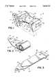
- FIG. 1is a rear perspective view of an orthodontic bracket according to one preferred embodiment of the present invention showing the bracket from the side that attaches to the tooth.
- FIG. 2is a perspective view of a ligature, according to a preferred embodiment of the invention, for attaching an archwire to the bracket of FIG. 1.
- FIG. 3is a perspective view similar to FIG. 2 showing the ligature uncoiled.
- FIG. 4is a perspective view of a portion of an orthodontic appliance illustrating a ligature and bracket assembly formed of the bracket and ligature of FIGS. 1 and 2 with an archwire secured thereto.
- FIG. 5is a perspective view, similar to FIG. 4, but illustrating a ligature of alternative dimensions forming an assembly with an alternative form of bracket of FIG. 1 in a configuration for holding the an archwire more tightly thereto.
- FIG. 6is a side elevational view, partially in cross section, showing a first step of the preferred embodiment of the method of the invention for ligating an archwire to the bracket.
- FIG. 7is a side elevational view, similar to FIG. 6, showing a second step of the preferred embodiment of the method of the invention for ligating an archwire to the bracket.
- FIG. 8is a side elevational view, similar to FIG. 6, showing a third step of the preferred embodiment of the method of the invention for ligating an archwire to the bracket.
- FIG. 9is a side elevational view, similar to FIG. 6, showing a fourth step of the preferred embodiment of the method of the invention for ligating an archwire to the bracket.
- the bracket 10has a base 11 in the form of a mounting surface to be secured to the crown surface of the tooth of a patient, usually by bonding with special orthodontic appliance adhesive.
- the base 11is preferably formed on a bracket pad 12 (shown partially broken away) that generally rectangular in shape.
- the base mounting surface 11is conventionally provided with a mesh laminate (not shown) to facilitate the adhesion of bonding of the mounting surface 11 to the crown surface of a tooth.
- the bracket 10is provide with a cylindrical post 15 that is rigidly supported relative to the pad 12 such that it is maintained in a fixed spaced relationship to the surface of the tooth on which the bracket 10 is mounted.
- the post 15is preferably cylindrical and is supported relative to the base 11 such that its axis 16 is aligned horizontally with what may be defined as the longitudinal dimension of the post 15.
- the posthas a transverse dimension defining the thickness of the post 15, which in the preferred embodiment is the diameter of the cylinder.
- the bracket 10is provided with a support 18 which maintains the post 15 in its spaced relationship with the pad 12.
- the support 18is made up of a pair of spaced legs 21 and 22.
- the opposite ends of the post 15are rigidly connected to the legs 21 and 22 such that the post 15 extends horizontally between the legs 21 and 22.
- Each of the legs 21 and 22has a respective foot 23 and 24 which are rigidly attached to the pad 12.
- the bracketmay be formed without the separate pad 12, in which case the mounting surface or base 11 of the bracket 10 is formed directly on the surfaces of the feet 23 and 24.
- an archwire slot 25that is of rectangular cross-section to receive an archwire, e.g. 30 (FIGS. 4 and 5), usually also of rectangular cross-section.
- the slot 25is formed in the post 15 on the side thereof that faces away from the base 11, parallel to the axis 16 of the post 15.
- the slot 25also continues through the legs 21 and 22 of the support 18 to receive the archwire 30.
- the outer surface of the post 15constitutes a ligating surface 33 about which a ligature may be tied to secure the archwire 30 in the slot 25 of the bracket 10.
- This surfaceis generally cylindrical such that a ligature wound around it will generally form a circle and will confine an archwire 30 in the slot 25 of the bracket 10.
- the ligating surface 33 of the post 15is configured to permit an archwire 30 to be held in the slot 25 to differing degrees of tightness, or to hold wires of different thickness to the same or different tightnesses.
- the ligating surface 33is preferably stepped, having a pair of larger diameter surface portions 34,35 adjacent the legs 21, 22, and a central smaller diameter portion 36 between the portions 34,35.
- the ligature 40includes an elongated band 41 of a flat spring-like material, such as, for example, stainless steel or nickel-titanium alloy, that is preferably coated with a low friction material such as TEFLONTM.
- the ligature 40is shown in FIG. 2 with the band 41 in an unstressed condition, in which it assumes a coiled shape of generally circular form with a diameter less than that of the portion 34,35 or 36 of the cylindrical surface 33 of the post 15 on which it is designed to be wound.
- the ligature 40also includes a removable and disposable elongated installation strip 42 to which the band 41 is removably secured, such as with a forward end 43 thereof being inserted into a slot 45 in or near a leading end 47 of the strip 42.
- the band 41is attached to the strip 42 such that, when the band 41 is coiled, the strip 42 lies on the outside of the band 41.
- the strip 42is formed of a plastic material such as MYLARTM. With this arrangement, the band 41 coils to a slightly smaller diameter, causing the forward end 43 of the band 41 to urge forward into the slot 45.
- the ligature 40is laid flat, as illustrated in FIG. 3, the forward end 43 of the band 41 tends to move rearwardly away from leading end 47 of the strip 42.
- the band 41has a terminal end 48 that is hooked.
- the hooked terminal end 48is formed by a pair of tabs 50 projecting sidewardly from the terminal end 48 of the band 41, formed integrally of the spring-like material of which the band 41 is made.
- the band 41is preferably, but not necessarily, shorter than the strip 42, such that then the band 41 and strip 42 are assembled with the forward end 43 of the band 41 in the slot 45, the strip 42 has a trailing end 52 that extends beyond the terminal end 48 of the band 41.
- the strip 42is also provided with a hole 54 in the leading end 47 thereof that serves as a handle by which the strip 42, and the assembled ligature 40 that includes the band 41 attached to the strip 42, can be pulled with the use of a tool having a hooked end, or by a short piece of cord that may be tied to the strip 42 through the hole 54.
- the bands 41are provided in a plurality of widths for use with the same bracket 10.
- the pluralityis two.
- a band 41a of the first widthis illustrated in FIG. 4, wound about the ligating surface 33 of the post 15 such that it rests on the larger diameter portions 34,35 of the surface 33.
- a larger wire 30may be held in the slot 25, or, alternatively, a smaller wire 30 may be loosely held in the slot 25.
- a band 41b of a second width narrower than the width of band 41a(FIG. 4) is shown wound to a smaller diameter around the center portion 36 of the ligating surface 33, whereby a smaller wire 30 may be held in the slot 25, or the same size wire 30 may be held more tightly than with the band 41a.
- the tabs 50are dimensioned to extend to both sides of the ligating surface 33 such they will not fit between the legs 21 and 22, so as to form a stop that pulls the band 41 from the strip 42.
- the support 18is provided with a pair of shoulders 57,58 formed in the respective legs 21,22 near the feet thereof 23,24, respectively.
- bracket 10 and the ligature 40interact to form a bracket and ligature assembly, a plurality of which cooperate to connect one or two orthodontic archwires 30 to the teeth of a patient to form an orthodontic appliance.
- the use of the assemblyis preferably in accordance with the preferred method of the invention.
- FIG. 6The preferred method of ligating an archwire 30 to a bracket 10, according to the present invention, is illustrated by the drawing sequence of drawings, FIGS. 6-9.
- a bracket 10is shown bonded at the mounting surface 11 on the pad 12 thereof to a crown surface 60 of a tooth 61 of a patient, such that the post 15 of the bracket 10 is spaced from the pad 12, by the supports 21,22 (21 only shown) leaving a space 64 between the ligating surface 33 and the pad 12.
- the orthodontistinserts an archwire 30 in the slots 25 of each of the brackets 10. Then the orthodontist ties the wire 30 to the brackets 10.
- the orthodontisttakes a pre-assembled ligature 40 and inserts the leading end 47 of the strip 42 through the space 64 between the pad 12 and the post 15.
- the end 47is inserted from the side of the bracket 10 on which the shoulders 57,58 are formed in the legs 21,22 of the support 18.
- the bracket 10is mounted on the teeth 61 such that the shoulders 57,58 are toward the patient's gum.
- the ligature so insertedis illustrated in FIG. 7, with the leading end 47 of the strip 42 projecting through the space 64, exposing the hole 54 therein.
- the orthodontisttakes a hooked tool, for example as illustrated at 66, and inserts the hooked end 67 thereof through the hole 54, Then, the orthodontist pulls the hook 66 and thus the entire ligature 40 partially through the space 64 until the tabs 50 that form the hooked terminal end 48 are in engagement with the shoulders 57,58, thereby preventing the band 41 from being pulled further through the space 64. Because the diameter of the coil formed by the unstressed ligature is greater than the dimension between the pad 12 and the post 15, the ligature 40 uncoils as it is pulled through the space 64. When the tabs 50 engage the shoulders 57,58 and stop the movement of the band 41, the strip 42 is not so restrained, and therefore, as illustrated in FIG.
- the length of the band 41is such that it makes one complete encirclement of the post 25 with the wire 30 in the slot 25.
- the stripmay, however be less than the circumference of the ligating surface 33, provided that it is constrained about the post 15 to the extend that it is not allowed to uncover the archwire slot 25 to allow the wire 30 to move from the slot 25.
- the band 41may also be longer than one circumference of the ligating surface 33 of the post 25, but should not be so long that the forward end 43 thereof extends into the space 64 again or hits the surface of the tooth 61 as the band 41 winds about the post 25.
- the band 41when released by the strip 42, tends to coil a diameter that is less than that of the ligating surface 33 of the post 15, whether the band 41 is of the width designed for engagement with the outer portions 34,35 of the surface 33 or with the smaller diameter inner portion 36 of the surface 33. In either case, the band 41 securely holds the wire 30 in the slot 25.
- the tieing of the wire 30 to the brackets 10quick and easy for the orthodontist to accomplish with the assembly and method of the present.
- the ligated bracketprovides a lower profile than the currently used tie-wing brackets of the prior art, giving less interference and a cosmetically improved appliance, that can be hygienically maintained easier than can appliances of the prior art.
Landscapes
- Health & Medical Sciences (AREA)
- Oral & Maxillofacial Surgery (AREA)
- Dentistry (AREA)
- Epidemiology (AREA)
- Life Sciences & Earth Sciences (AREA)
- Animal Behavior & Ethology (AREA)
- General Health & Medical Sciences (AREA)
- Public Health (AREA)
- Veterinary Medicine (AREA)
- Dental Tools And Instruments Or Auxiliary Dental Instruments (AREA)
Abstract
Description
Claims (16)
Priority Applications (1)
| Application Number | Priority Date | Filing Date | Title |
|---|---|---|---|
| US08/489,501US5618176A (en) | 1995-06-12 | 1995-06-12 | Orthodontic bracket and ligature and method of ligating archwire to bracket |
Applications Claiming Priority (1)
| Application Number | Priority Date | Filing Date | Title |
|---|---|---|---|
| US08/489,501US5618176A (en) | 1995-06-12 | 1995-06-12 | Orthodontic bracket and ligature and method of ligating archwire to bracket |
Publications (1)
| Publication Number | Publication Date |
|---|---|
| US5618176Atrue US5618176A (en) | 1997-04-08 |
Family
ID=23944136
Family Applications (1)
| Application Number | Title | Priority Date | Filing Date |
|---|---|---|---|
| US08/489,501Expired - Fee RelatedUS5618176A (en) | 1995-06-12 | 1995-06-12 | Orthodontic bracket and ligature and method of ligating archwire to bracket |
Country Status (1)
| Country | Link |
|---|---|
| US (1) | US5618176A (en) |
Cited By (27)
| Publication number | Priority date | Publication date | Assignee | Title |
|---|---|---|---|---|
| US6247923B1 (en)* | 2000-05-24 | 2001-06-19 | Nikhil Shankarlal Vashi | Self-locking orthodontic bracket |
| US6318995B1 (en) | 2000-04-19 | 2001-11-20 | Drametrix, Inc. | Method and apparatus for bonding a bracket to a tooth |
| US6413084B1 (en) | 2000-04-28 | 2002-07-02 | Ora Metrix, Inc. | Method and system of scanning |
| US6464496B1 (en) | 1999-11-30 | 2002-10-15 | Orametrix, Inc. | Method and apparatus for determining and monitoring orthodontic treatment |
| US6512994B1 (en) | 1999-11-30 | 2003-01-28 | Orametrix, Inc. | Method and apparatus for producing a three-dimensional digital model of an orthodontic patient |
| US6532299B1 (en) | 2000-04-28 | 2003-03-11 | Orametrix, Inc. | System and method for mapping a surface |
| US6554613B1 (en) | 2000-04-19 | 2003-04-29 | Ora Metrix, Inc. | Method and apparatus for generating an orthodontic template that assists in placement of orthodontic apparatus |
| US6587828B1 (en) | 1999-11-30 | 2003-07-01 | Ora Metrix, Inc. | Method and apparatus for automated generation of a patient treatment plan |
| US20040002873A1 (en)* | 1999-11-30 | 2004-01-01 | Orametrix, Inc. | Method and apparatus for automated generation of a patient treatment plan |
| US6688885B1 (en) | 1999-11-30 | 2004-02-10 | Orametrix, Inc | Method and apparatus for treating an orthodontic patient |
| US6738508B1 (en) | 2000-04-28 | 2004-05-18 | Orametrix, Inc. | Method and system for registering data |
| US6736638B1 (en) | 2000-04-19 | 2004-05-18 | Orametrix, Inc. | Method and apparatus for orthodontic appliance optimization |
| US6744932B1 (en) | 2000-04-28 | 2004-06-01 | Orametrix, Inc. | System and method for mapping a surface |
| US6744914B1 (en) | 2000-04-28 | 2004-06-01 | Orametrix, Inc. | Method and system for generating a three-dimensional object |
| US6771809B1 (en) | 2000-04-28 | 2004-08-03 | Orametrix, Inc. | Method and system for registering data |
| US6851949B1 (en) | 1999-11-30 | 2005-02-08 | Orametrix, Inc. | Method and apparatus for generating a desired three-dimensional digital model of an orthodontic structure |
| US20050255422A1 (en)* | 2004-05-11 | 2005-11-17 | Cordato Mark A | Orthodontic bracket and clip |
| US7068836B1 (en) | 2000-04-28 | 2006-06-27 | Orametrix, Inc. | System and method for mapping a surface |
| WO2007120920A2 (en) | 2006-04-17 | 2007-10-25 | Align Technology, Inc. | Digitization of target dental arch model |
| US20090325120A1 (en)* | 2007-07-23 | 2009-12-31 | Ultradent Products, Inc. | Self-ligating orthodontic bracket with sliding ligation cover |
| WO2011090502A1 (en)* | 2010-01-22 | 2011-07-28 | Ultradent Products, Inc. | Customized orthodontic arch wire manufactured using model of patient's teeth |
| US9089386B2 (en) | 2012-11-16 | 2015-07-28 | World Class Technology Corporation | Self-ligating bracket with sliding cover |
| US9301815B2 (en)* | 2007-03-14 | 2016-04-05 | John Joseph Dumas | Orthodontic connector assembly and a method for treating teeth |
| US9939999B2 (en) | 2005-04-29 | 2018-04-10 | Align Technology, Inc. | Treatment of teeth by aligners |
| US10085824B2 (en) | 2015-10-30 | 2018-10-02 | Ortho Organizers, Inc. | Self ligating orthodontic bracket |
| US10265142B2 (en)* | 2014-03-18 | 2019-04-23 | Christoph Von Mandach | Kit and system for assembling an orthodontic bracket |
| US10376341B2 (en) | 2013-12-06 | 2019-08-13 | 3M Innovative Properties Company | Labial attachment device for use with orthodontic auxiliary and lingual appliance system |
Citations (17)
| Publication number | Priority date | Publication date | Assignee | Title |
|---|---|---|---|---|
| US3043006A (en)* | 1959-06-02 | 1962-07-10 | Wallshein Melvin | Orthodontic brackets |
| US3091857A (en)* | 1961-02-15 | 1963-06-04 | James M Rubin | Orthodontic device |
| US4074433A (en)* | 1976-09-07 | 1978-02-21 | Hamilton Technology, Inc. | Intermaxillary tooth moving device |
| US4149314A (en)* | 1977-02-18 | 1979-04-17 | Nonnenmann Michael J | Orthodontic brackets with pivotal fastenings |
| US4193195A (en)* | 1978-07-20 | 1980-03-18 | American Orthodontics Corporation | Orthodontic appliance |
| US4371337A (en)* | 1981-05-20 | 1983-02-01 | Pletcher Erwin Carroll | Orthodontic bracket |
| US4427381A (en)* | 1982-11-22 | 1984-01-24 | Tp Laboratories, Inc. | Combination light wire and edgewise appliance |
| US4492573A (en)* | 1984-03-27 | 1985-01-08 | Augusta Developments Inc. | Orthodontic bracket |
| US4496318A (en)* | 1982-05-17 | 1985-01-29 | Connelly Jr Harold R | Converters for orthodontic treatment |
| US4565526A (en)* | 1984-06-28 | 1986-01-21 | Sankin Industry Co., Ltd. | Orthodontic appliance |
| US4725229A (en)* | 1986-06-18 | 1988-02-16 | Ormco Corporation | Orthodontic bracket |
| US4786252A (en)* | 1984-12-13 | 1988-11-22 | Kinya Fujita | Orthodontic appliance |
| US5094614A (en)* | 1991-03-08 | 1992-03-10 | Wildman Alexander J | Miniature self-locking labial bracket |
| US5123838A (en)* | 1990-12-13 | 1992-06-23 | Cannon James L | Orthodontic bracket |
| US5224858A (en)* | 1992-01-28 | 1993-07-06 | Hamilton Ortho Inc. | Orthodontic brackets and arch wires for use in combination therewith |
| US5275557A (en)* | 1993-04-08 | 1994-01-04 | Damon Dwight H | Self-locking orthodontic bracket |
| US5362233A (en)* | 1993-02-22 | 1994-11-08 | Thompson William J | Orthodontic appliance |
- 1995
- 1995-06-12USUS08/489,501patent/US5618176A/ennot_activeExpired - Fee Related
Patent Citations (17)
| Publication number | Priority date | Publication date | Assignee | Title |
|---|---|---|---|---|
| US3043006A (en)* | 1959-06-02 | 1962-07-10 | Wallshein Melvin | Orthodontic brackets |
| US3091857A (en)* | 1961-02-15 | 1963-06-04 | James M Rubin | Orthodontic device |
| US4074433A (en)* | 1976-09-07 | 1978-02-21 | Hamilton Technology, Inc. | Intermaxillary tooth moving device |
| US4149314A (en)* | 1977-02-18 | 1979-04-17 | Nonnenmann Michael J | Orthodontic brackets with pivotal fastenings |
| US4193195A (en)* | 1978-07-20 | 1980-03-18 | American Orthodontics Corporation | Orthodontic appliance |
| US4371337A (en)* | 1981-05-20 | 1983-02-01 | Pletcher Erwin Carroll | Orthodontic bracket |
| US4496318A (en)* | 1982-05-17 | 1985-01-29 | Connelly Jr Harold R | Converters for orthodontic treatment |
| US4427381A (en)* | 1982-11-22 | 1984-01-24 | Tp Laboratories, Inc. | Combination light wire and edgewise appliance |
| US4492573A (en)* | 1984-03-27 | 1985-01-08 | Augusta Developments Inc. | Orthodontic bracket |
| US4565526A (en)* | 1984-06-28 | 1986-01-21 | Sankin Industry Co., Ltd. | Orthodontic appliance |
| US4786252A (en)* | 1984-12-13 | 1988-11-22 | Kinya Fujita | Orthodontic appliance |
| US4725229A (en)* | 1986-06-18 | 1988-02-16 | Ormco Corporation | Orthodontic bracket |
| US5123838A (en)* | 1990-12-13 | 1992-06-23 | Cannon James L | Orthodontic bracket |
| US5094614A (en)* | 1991-03-08 | 1992-03-10 | Wildman Alexander J | Miniature self-locking labial bracket |
| US5224858A (en)* | 1992-01-28 | 1993-07-06 | Hamilton Ortho Inc. | Orthodontic brackets and arch wires for use in combination therewith |
| US5362233A (en)* | 1993-02-22 | 1994-11-08 | Thompson William J | Orthodontic appliance |
| US5275557A (en)* | 1993-04-08 | 1994-01-04 | Damon Dwight H | Self-locking orthodontic bracket |
Cited By (36)
| Publication number | Priority date | Publication date | Assignee | Title |
|---|---|---|---|---|
| US7003472B2 (en) | 1999-11-30 | 2006-02-21 | Orametrix, Inc. | Method and apparatus for automated generation of a patient treatment plan |
| US6464496B1 (en) | 1999-11-30 | 2002-10-15 | Orametrix, Inc. | Method and apparatus for determining and monitoring orthodontic treatment |
| US6512994B1 (en) | 1999-11-30 | 2003-01-28 | Orametrix, Inc. | Method and apparatus for producing a three-dimensional digital model of an orthodontic patient |
| US6587828B1 (en) | 1999-11-30 | 2003-07-01 | Ora Metrix, Inc. | Method and apparatus for automated generation of a patient treatment plan |
| US20040002873A1 (en)* | 1999-11-30 | 2004-01-01 | Orametrix, Inc. | Method and apparatus for automated generation of a patient treatment plan |
| US6688885B1 (en) | 1999-11-30 | 2004-02-10 | Orametrix, Inc | Method and apparatus for treating an orthodontic patient |
| US6851949B1 (en) | 1999-11-30 | 2005-02-08 | Orametrix, Inc. | Method and apparatus for generating a desired three-dimensional digital model of an orthodontic structure |
| US6736638B1 (en) | 2000-04-19 | 2004-05-18 | Orametrix, Inc. | Method and apparatus for orthodontic appliance optimization |
| US6318995B1 (en) | 2000-04-19 | 2001-11-20 | Drametrix, Inc. | Method and apparatus for bonding a bracket to a tooth |
| US6918761B2 (en) | 2000-04-19 | 2005-07-19 | Orametrix, Inc. | Method and apparatus for generating an orthodontic template that assists in placement of orthodontic apparatus |
| US6554613B1 (en) | 2000-04-19 | 2003-04-29 | Ora Metrix, Inc. | Method and apparatus for generating an orthodontic template that assists in placement of orthodontic apparatus |
| US20030194677A1 (en)* | 2000-04-19 | 2003-10-16 | Orametrix, Inc. | Method and apparatus for generating an orthodontic template that assists in placement of orthodontic apparatus |
| US6532299B1 (en) | 2000-04-28 | 2003-03-11 | Orametrix, Inc. | System and method for mapping a surface |
| US6744932B1 (en) | 2000-04-28 | 2004-06-01 | Orametrix, Inc. | System and method for mapping a surface |
| US6744914B1 (en) | 2000-04-28 | 2004-06-01 | Orametrix, Inc. | Method and system for generating a three-dimensional object |
| US6771809B1 (en) | 2000-04-28 | 2004-08-03 | Orametrix, Inc. | Method and system for registering data |
| US6738508B1 (en) | 2000-04-28 | 2004-05-18 | Orametrix, Inc. | Method and system for registering data |
| US7068836B1 (en) | 2000-04-28 | 2006-06-27 | Orametrix, Inc. | System and method for mapping a surface |
| US6413084B1 (en) | 2000-04-28 | 2002-07-02 | Ora Metrix, Inc. | Method and system of scanning |
| US6247923B1 (en)* | 2000-05-24 | 2001-06-19 | Nikhil Shankarlal Vashi | Self-locking orthodontic bracket |
| US20050255422A1 (en)* | 2004-05-11 | 2005-11-17 | Cordato Mark A | Orthodontic bracket and clip |
| US7033170B2 (en) | 2004-05-11 | 2006-04-25 | Mark Andrew Cordato | Orthodontic bracket and clip |
| US9939999B2 (en) | 2005-04-29 | 2018-04-10 | Align Technology, Inc. | Treatment of teeth by aligners |
| US11789594B2 (en) | 2005-04-29 | 2023-10-17 | Align Technology, Inc. | Treatment of teeth by aligners |
| US11379097B2 (en) | 2005-04-29 | 2022-07-05 | Align Technology, Inc. | Treatment of teeth by aligners |
| US11086490B2 (en) | 2005-04-29 | 2021-08-10 | Align Technology, Inc. | Treatment of teeth by aligners |
| WO2007120920A2 (en) | 2006-04-17 | 2007-10-25 | Align Technology, Inc. | Digitization of target dental arch model |
| US9301815B2 (en)* | 2007-03-14 | 2016-04-05 | John Joseph Dumas | Orthodontic connector assembly and a method for treating teeth |
| US7963767B2 (en) | 2007-07-23 | 2011-06-21 | Ultradent Products, Inc. | Self-ligating orthodontic bracket with sliding ligation cover |
| US20090325120A1 (en)* | 2007-07-23 | 2009-12-31 | Ultradent Products, Inc. | Self-ligating orthodontic bracket with sliding ligation cover |
| WO2011090502A1 (en)* | 2010-01-22 | 2011-07-28 | Ultradent Products, Inc. | Customized orthodontic arch wire manufactured using model of patient's teeth |
| US10631957B2 (en) | 2012-11-16 | 2020-04-28 | World Class Technology Corporation | Self-ligating bracket with sliding cover |
| US9089386B2 (en) | 2012-11-16 | 2015-07-28 | World Class Technology Corporation | Self-ligating bracket with sliding cover |
| US10376341B2 (en) | 2013-12-06 | 2019-08-13 | 3M Innovative Properties Company | Labial attachment device for use with orthodontic auxiliary and lingual appliance system |
| US10265142B2 (en)* | 2014-03-18 | 2019-04-23 | Christoph Von Mandach | Kit and system for assembling an orthodontic bracket |
| US10085824B2 (en) | 2015-10-30 | 2018-10-02 | Ortho Organizers, Inc. | Self ligating orthodontic bracket |
Similar Documents
| Publication | Publication Date | Title |
|---|---|---|
| US5618176A (en) | Orthodontic bracket and ligature and method of ligating archwire to bracket | |
| US6709268B2 (en) | Orthodontic appliance with contoured retaining guide | |
| US3936938A (en) | Orthodontic spring appliance and spring clip therefor | |
| US4193195A (en) | Orthodontic appliance | |
| US5474444A (en) | Multiwire arch system | |
| US3964165A (en) | Elastomeric orthodontic apparatus | |
| US6733285B2 (en) | Orthodontic appliance with lingual retaining groove | |
| JP4534232B2 (en) | Orthodontic devices for use with archwires | |
| EP1458303B1 (en) | Method and instrument for releasing an orthodontic archwire from an orthodontic appliance | |
| US5791897A (en) | Multiwire arch system with improved interarch connector | |
| US5685711A (en) | Self-ligating orthodontic brackets | |
| US10433935B1 (en) | Orthodontic devices for movement of impacted or malpositioned teeth | |
| US6358045B1 (en) | Self ligating orthodontic bracket | |
| US6655959B2 (en) | Orthodontic device for retraction/extension of teeth | |
| JPS59103658A (en) | Dental orthodontic bracket assembly | |
| JP2008284365A (en) | Orthodontic hook device and instrument system | |
| US3975823A (en) | Orthodontic torquing system | |
| US4522590A (en) | Ring for orthodontic bracket | |
| JP2006505328A (en) | Orthodontic treatment molar appliance | |
| US4416627A (en) | Orthodontic appliance | |
| US20120058444A1 (en) | Variable Extension Spring For Orthodontics | |
| US4227876A (en) | Orthodontic bracket | |
| US20110143301A1 (en) | Single continuous spring orthodontic bracket and system | |
| JPH10323355A (en) | Dental corrective device | |
| US12409017B2 (en) | Systems and methods for providing an orthodontic spring |
Legal Events
| Date | Code | Title | Description |
|---|---|---|---|
| AS | Assignment | Owner name:ORMCO CORPORATION, CALIFORNIA Free format text:ASSIGNMENT OF ASSIGNORS INTEREST;ASSIGNORS:ANDREIKO, CRAIG A.;PAYNE, MARK A.;REEL/FRAME:007585/0547 Effective date:19950609 | |
| FEPP | Fee payment procedure | Free format text:PAYOR NUMBER ASSIGNED (ORIGINAL EVENT CODE: ASPN); ENTITY STATUS OF PATENT OWNER: LARGE ENTITY | |
| FPAY | Fee payment | Year of fee payment:4 | |
| AS | Assignment | Owner name:ABN AMRO BANK N.V., ILLINOIS Free format text:SECURITY INTEREST;ASSIGNOR:ORMCO CORPORATION;REEL/FRAME:011400/0232 Effective date:20001211 | |
| AS | Assignment | Owner name:ORMCO CORPORATION, CALIFORNIA Free format text:SECURITY INTEREST;ASSIGNOR:ABN MARO BANK N.V.;REEL/FRAME:012946/0993 Effective date:20020606 Owner name:CREDIT SUISSE FIRST BOSTON, NEW YORK Free format text:SECURITY AGREEMENT;ASSIGNOR:ORMCO CORPORATION;REEL/FRAME:012958/0243 Effective date:20020606 | |
| REMI | Maintenance fee reminder mailed | ||
| LAPS | Lapse for failure to pay maintenance fees | ||
| STCH | Information on status: patent discontinuation | Free format text:PATENT EXPIRED DUE TO NONPAYMENT OF MAINTENANCE FEES UNDER 37 CFR 1.362 | |
| FP | Lapsed due to failure to pay maintenance fee | Effective date:20050408 | |
| AS | Assignment | Owner name:ORMCO CORPORATION, CALIFORNIA Free format text:RELEASE BY SECURED PARTY;ASSIGNOR:CREDIT SUISSE FIRST BOSTON (N/K/A CREDIT SUISSE, CAYMAN ISLANDS BRANCH);REEL/FRAME:017519/0456 Effective date:20060323 |