US5617085A - Method and apparatus for monitoring the surroundings of a vehicle and for detecting failure of the monitoring apparatus - Google Patents
Method and apparatus for monitoring the surroundings of a vehicle and for detecting failure of the monitoring apparatusDownload PDFInfo
- Publication number
- US5617085A US5617085AUS08/652,683US65268396AUS5617085AUS 5617085 AUS5617085 AUS 5617085AUS 65268396 AUS65268396 AUS 65268396AUS 5617085 AUS5617085 AUS 5617085A
- Authority
- US
- United States
- Prior art keywords
- vehicle
- lane
- coordinates
- camera
- laser radar
- Prior art date
- Legal status (The legal status is an assumption and is not a legal conclusion. Google has not performed a legal analysis and makes no representation as to the accuracy of the status listed.)
- Expired - Lifetime
Links
Images


Classifications
- B—PERFORMING OPERATIONS; TRANSPORTING
- B60—VEHICLES IN GENERAL
- B60Q—ARRANGEMENT OF SIGNALLING OR LIGHTING DEVICES, THE MOUNTING OR SUPPORTING THEREOF OR CIRCUITS THEREFOR, FOR VEHICLES IN GENERAL
- B60Q9/00—Arrangement or adaptation of signal devices not provided for in one of main groups B60Q1/00 - B60Q7/00, e.g. haptic signalling
- B60Q9/008—Arrangement or adaptation of signal devices not provided for in one of main groups B60Q1/00 - B60Q7/00, e.g. haptic signalling for anti-collision purposes
- G—PHYSICS
- G01—MEASURING; TESTING
- G01S—RADIO DIRECTION-FINDING; RADIO NAVIGATION; DETERMINING DISTANCE OR VELOCITY BY USE OF RADIO WAVES; LOCATING OR PRESENCE-DETECTING BY USE OF THE REFLECTION OR RERADIATION OF RADIO WAVES; ANALOGOUS ARRANGEMENTS USING OTHER WAVES
- G01S17/00—Systems using the reflection or reradiation of electromagnetic waves other than radio waves, e.g. lidar systems
- G01S17/86—Combinations of lidar systems with systems other than lidar, radar or sonar, e.g. with direction finders
- G—PHYSICS
- G01—MEASURING; TESTING
- G01S—RADIO DIRECTION-FINDING; RADIO NAVIGATION; DETERMINING DISTANCE OR VELOCITY BY USE OF RADIO WAVES; LOCATING OR PRESENCE-DETECTING BY USE OF THE REFLECTION OR RERADIATION OF RADIO WAVES; ANALOGOUS ARRANGEMENTS USING OTHER WAVES
- G01S17/00—Systems using the reflection or reradiation of electromagnetic waves other than radio waves, e.g. lidar systems
- G01S17/88—Lidar systems specially adapted for specific applications
- G01S17/93—Lidar systems specially adapted for specific applications for anti-collision purposes
- G01S17/931—Lidar systems specially adapted for specific applications for anti-collision purposes of land vehicles
- G—PHYSICS
- G06—COMPUTING OR CALCULATING; COUNTING
- G06V—IMAGE OR VIDEO RECOGNITION OR UNDERSTANDING
- G06V10/00—Arrangements for image or video recognition or understanding
- G06V10/20—Image preprocessing
- G06V10/255—Detecting or recognising potential candidate objects based on visual cues, e.g. shapes
- G—PHYSICS
- G06—COMPUTING OR CALCULATING; COUNTING
- G06V—IMAGE OR VIDEO RECOGNITION OR UNDERSTANDING
- G06V20/00—Scenes; Scene-specific elements
- G06V20/50—Context or environment of the image
- G06V20/56—Context or environment of the image exterior to a vehicle by using sensors mounted on the vehicle
- G06V20/58—Recognition of moving objects or obstacles, e.g. vehicles or pedestrians; Recognition of traffic objects, e.g. traffic signs, traffic lights or roads
- G—PHYSICS
- G06—COMPUTING OR CALCULATING; COUNTING
- G06V—IMAGE OR VIDEO RECOGNITION OR UNDERSTANDING
- G06V20/00—Scenes; Scene-specific elements
- G06V20/50—Context or environment of the image
- G06V20/56—Context or environment of the image exterior to a vehicle by using sensors mounted on the vehicle
- G06V20/588—Recognition of the road, e.g. of lane markings; Recognition of the vehicle driving pattern in relation to the road
- G—PHYSICS
- G08—SIGNALLING
- G08G—TRAFFIC CONTROL SYSTEMS
- G08G1/00—Traffic control systems for road vehicles
- G08G1/16—Anti-collision systems
- G08G1/166—Anti-collision systems for active traffic, e.g. moving vehicles, pedestrians, bikes
- G—PHYSICS
- G08—SIGNALLING
- G08G—TRAFFIC CONTROL SYSTEMS
- G08G1/00—Traffic control systems for road vehicles
- G08G1/16—Anti-collision systems
- G08G1/167—Driving aids for lane monitoring, lane changing, e.g. blind spot detection
- B—PERFORMING OPERATIONS; TRANSPORTING
- B60—VEHICLES IN GENERAL
- B60T—VEHICLE BRAKE CONTROL SYSTEMS OR PARTS THEREOF; BRAKE CONTROL SYSTEMS OR PARTS THEREOF, IN GENERAL; ARRANGEMENT OF BRAKING ELEMENTS ON VEHICLES IN GENERAL; PORTABLE DEVICES FOR PREVENTING UNWANTED MOVEMENT OF VEHICLES; VEHICLE MODIFICATIONS TO FACILITATE COOLING OF BRAKES
- B60T2201/00—Particular use of vehicle brake systems; Special systems using also the brakes; Special software modules within the brake system controller
- B60T2201/08—Lane monitoring; Lane Keeping Systems
- B60T2201/089—Lane monitoring; Lane Keeping Systems using optical detection
- G—PHYSICS
- G01—MEASURING; TESTING
- G01S—RADIO DIRECTION-FINDING; RADIO NAVIGATION; DETERMINING DISTANCE OR VELOCITY BY USE OF RADIO WAVES; LOCATING OR PRESENCE-DETECTING BY USE OF THE REFLECTION OR RERADIATION OF RADIO WAVES; ANALOGOUS ARRANGEMENTS USING OTHER WAVES
- G01S7/00—Details of systems according to groups G01S13/00, G01S15/00, G01S17/00
- G01S7/48—Details of systems according to groups G01S13/00, G01S15/00, G01S17/00 of systems according to group G01S17/00
- G01S7/497—Means for monitoring or calibrating
- G01S7/4972—Alignment of sensor
- G—PHYSICS
- G06—COMPUTING OR CALCULATING; COUNTING
- G06V—IMAGE OR VIDEO RECOGNITION OR UNDERSTANDING
- G06V2201/00—Indexing scheme relating to image or video recognition or understanding
- G06V2201/08—Detecting or categorising vehicles
Definitions
- the present inventionrelates to a method for monitoring the surroundings of a running vehicle and a vehicle-mounted apparatus for carrying out the method, including a camera and a laser radar for detection of vehicles on the road and in the lane of the vehicle.
- the present inventionalso relates to a method for judging failure of the monitoring apparatus by detection of coincidence between the optical axes of the camera and the laser radar.
- Japanese Laid-Open Patent Publication (unexamined) No. 113482/1993discloses a vehicle-mounted rear-end collision preventing apparatus.
- a laser radar of a single beam typefrom which a laser beam is emitted in one direction in a defined narrow range ahead of a vehicle, is associated with an image processing means, whereby an obstacle ahead in the vehicle's own traffic lane is detected.
- An object of this conventional apparatusis to detect an obstacle in the vehicle's own lane.
- the laser beam emitted from the vehicle's laser radardoes not irradiate the vehicle's own lane, but irradiates an adjacent lane on either the left or the right side of the vehicle.
- any obstacle ahead of the vehicle detected by the laser radaris not necessarily in the vehicle's own lane.
- an image ahead of a vehicle picked up by a camerais processed to detect the vehicle's own lane, and then the curvature ahead of the vehicle's own lane is detected. Then, direction of beam irradiation from the laser radar is adjusted in conformity with the curvature, whereby the laser beam correctly irradiates the vehicle's own lane at all times even though the road is curved ahead of the vehicle.
- Japanese Patent Publication (examined) No.6349/1986discloses a vehicle-mounted obstacle detecting apparatus.
- a laser beam emitted in the running direction of a vehicleperforms a two-dimensional scan, and reflected light from an obstacle is measured, whereby distance to the obstacle and the position thereof in the leftward or rightward direction are detected.
- the other vehicle running ahead in the vehicle's own laneis on left side of the vehicle.
- Japanese Laid-Open Patent Publication (unexamined) No. 113482/1993discloses a vehicle-mounted rear-end collision preventing apparatus in which the irradiation range of the laser beam is fixed. This allows for any obstacle ahead in the vehicle's own lane to be identified within a fixed range. In this apparatus, however, only an obstacle in the vehicle's own lane can be detected. Thus, the capability of the beam-scan type laser beam to monitor a wide range is not sufficiently utilized.
- an object of the present inventionto provide a surroundings monitoring method for monitoring the surroundings of a vehicle which is capable of identifying a detected object lying or running in a vehicle's own lane even when employing a laser radar of the beam-scan type, and a surroundings monitoring apparatus to carry out this method.
- This failure judgement methoduses the lack of coincidence of the optical axes of a laser radar beam, which is used to detect another vehicle, and a camera, which is used to detect the lane, in order to determine when a failure has occurred.
- the surroundings monitoring method for monitoring the surroundings of a vehicle in accordance with the present inventioncomprises the steps of: (1) detecting image signals of a lane in which the vehicle is located with a camera mounted on the vehicle; (2) determining coordinates of the lane on a display image by processing the image signals; (3) detecting an object ahead of the vehicle with a beam-scan type laser radar the center of whose optical axes are coincident with the optical axes of the camera; transforming coordinates of the detected object in conformity with coordinate axes on the display image; and (5) judging whether the detected object is within the lane of the vehicle by comparing the transformed coordinates with the coordinates of the lane.
- the axes of the beam-scan type laser radar and the axes of the cameraare preliminarily coincided with each other.
- the camerapicks up an image of the road lying ahead of the vehicle, and processes the image signals to detect the vehicle's own lane.
- the laser radardetects a distance and a direction from the vehicle to the detected object.
- the distance and directionrepresent positional data of the detected object, which are then subject to a coordinate transformation to acknowledge the position on the image picked up by the camera.
- the coordinates of the detected object after the coordinate transformationare then compared with the coordinates of the vehicle's own lane on the display image picked up by the camera.
- the detected objectis within the scope of the coordinates indicating the vehicle's own lane, it is judged that the detected object is within the vehicle's own lane. On the other hand, if the detected object is outside the scope of the coordinates indicating the vehicle's own lane, it is judged that the detected object is not an object within the vehicle's own lane.
- the image of the road picked up by the camerais processed by the lane detecting means, whereby the vehicle's own lane is detected.
- the laser radar of the beam-scan typewhose optical axes are coincident with that of the camera performs a scan with a laser beam and detects a distance and a direction from the driver's vehicle to the detected object.
- Such positional information as distance and direction to the detected objectis provided to the coordinate transforming means and transformed to positional information of the coordinates on the display image of the camera.
- the forward vehicle detecting means(or separating means) the positional information of the vehicle's own lane indicated in the coordinates of the display image of the camera is compared with the positional information of the detected object. As a result of the comparison, a detected object existing within the vehicle's own lane is separated or distinguished from another detected object not existing within the vehicle's own lane.
- the surroundings monitoring apparatusfurther comprises a representative coordinate computing means for computing representative coordinates of the objects detected by the laser radar, so that the representative coordinates computed by the representative coordinate computing means are transformed in conformity with coordinate axes on the display image.
- the failure judging method for judging a failure of the surroundings monitoring apparatus caused by misalignment between the laser radar and the cameracomprises the steps of: (1) computing representative coordinates of another vehicle detected by the laser radar; (2) transforming the representative coordinates in conformity with coordinate axes of a display image detected by the camera; (3) setting a window for designating a prescribed region on the basis of the transformed representative coordinates of the other vehicle; (4) processing image signals in the window and judging whether or not the optical axes of the camera are coincident with the optical axes of the laser radar depending upon whether the other vehicle is within the window.
- the failure judging methodis to perform judgment of a failure of the surroundings monitoring apparatus provided with a laser radar and a camera whose optical axes are coincident with each other. First, the other vehicle existing in the vicinity is detected by the laser radar. Then, the place where the other vehicle is picked up on the image of the camera is computed, and a prescribed region of the image which includes the other vehicle is established.
- the image of the camerais then processed, and whether or not the optical axis of the camera is coincident with the optical axis of the laser radar is judged depending upon whether or not the vehicle is within the established prescribed region. In other words, if the optical axes of the camera and that of the laser radar are coincident, the detected object picked up by the laser radar must be also picked up by the camera. On the other hand, if the detected object picked up by the laser radar is not picked up by the camera, it may be judged that the optical axes are not coincident.
- the failure judgment apparatus for judging a failure of the above-mentioned surroundings monitoring apparatus, to carry out the foregoing failure judging methodcomprises: (1) a camera having an optical axis, the camera being mounted on the vehicle for picking up an image of a road; (2) a beam-scan type laser radar having an optical axis mounted on the vehicle and installed such that an optical axis center thereof is coincident with the optical axis of the camera; (3) a representative coordinate computing means for computing representative coordinates of another vehicle detected by the laser radar; (4) a coordinate transforming means for transforming the representative coordinates in conformance with coordinate axes on a display image of the camera; (5) a window setting means for setting a window for designating a prescribed region on the basis of the representative coordinates transformed by the coordinate transforming means; (6) an optical axis judging means for judging whether or not the optical axis of the camera is coincident with the optical axis of the laser radar depending upon whether or not the other vehicle is within the window by processing image signals in the window.
- the optical axis judging meansdetermines whether the object to be detected is within the window by comparing the transformed representative coordinates with histograms of the detected outline. This function determines whether the optical axes of the camera and the laser beam are coincident.
- the optical axis judging meanscomprises a histogram computing means, a comparative reference value setting means, and a comparing means.
- the histogram computing meanscomputes histograms representing the horizontal and vertical lines found within the outline.
- the comparative reference value setting meanssets comparative reference values based on the transformed coefficients.
- the comparing meanscompares the histograms with the comparative reference values based on the transformed coefficients, and judges that the other vehicle is within the corrected window when the maximum value of the histogram is greater than the comparative reference value for a prescribed period of time.
- the comparative reference value serving as a reference for judging the dimensions of the window set on the display image and for judging whether or not the vehicle existsis corrected corresponding to the distance to the other vehicle detected by the laser radar. Accordingly, even if the distance to the vehicle detected by the laser radar varies, coincidence or non-coincidence between the optical axes of the camera and laser radar is accurately judged.
- the failure judging apparatusfurther comprises an optical axis judgment inhibiting means.
- This deviceinhibits the judgment of coincidence or non-coincidence between the optical axes of the camera and laser radar when the distance indicated by the representative coordinates detected by the laser radar is over a prescribed distance. More specifically, the dimensions of the window and value of the comparative reference are corrected corresponding to the distance to the other vehicle detected by the laser radar.
- the distance to the other vehicleis excessively large, the image of the other vehicle on the display of the camera is excessively small, making it difficult to judge whether or not it is an image of another vehicle. Accordingly, the result of coincidence judgment obtained is not always reliable.
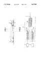
- FIG. 1is an explanatory view showing a vehicle mounted with apparatus proposed by several embodiments of the present invention
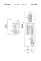
- FIG. 2is a block diagram showing an arrangement of a first preferred embodiment
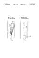
- FIG. 3shows an image of a road lying ahead picked up by a CCD camera mounted on the vehicle
- FIGS. 4(a), 4(b) and 4(c)are explanatory views showing positional information of a vehicle running ahead in respective coordinate systems;
- FIG. 5is an explanatory view showing a manner of detecting a vehicle running ahead by a laser radar mounted on the vehicle;
- FIG. 6is an explanatory view showing a manner of detecting a vehicle running ahead by the CCD camera mounted on the vehicle;
- FIG. 7is an explanatory view showing a manner of transforming positional information of an object detected by the laser radar in conformity with the coordinates on the display image;
- FIG. 8is a block diagram showing an arrangement of a second preferred embodiment
- FIGS. 9(a) and 9(b)are explanatory views to explain the operation of the representative coordinates computing means, where FIG. 9(a) is an explanatory view showing a manner of getting plural positional information using a laser radar from a vehicle running ahead, and FIG. 9(b) is an explanatory view showing a manner of integrating the plural positional information into one representative point;
- FIG. 10is a block diagram showing an arrangement of a third preferred embodiment
- FIG. 11is a block diagram showing a preferred arrangement of the optical axes non-coincidence detecting means employed in the third preferred embodiment.
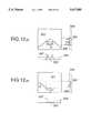
- FIGS. 12(a) and 12(b)are explanatory views to explain the operation of the third preferred embodiment.
- the first preferred embodimentproposes a surroundings monitoring method for monitoring the surroundings of a vehicle to judge whether or not an object detected by a beam-scan type laser radar is within a vehicle's own lane, and in addition a surroundings monitoring apparatus to carry out such a method.
- the surroundings monitoring methodis performed by the following steps.
- image signalsare detected by a camera mounted on a vehicle, directed in the direction of motion of the vehicle.
- the camerapicks up and processes white lines drawn on the road surface ahead of the vehicle. Since the camera is mounted on the vehicle, the camera is within the vehicle's own lane, from which the situation ahead is picked up.
- a white line on the left side of the vehicle's own lanecomes out on the left side of the image picked up by the camera, while a white line on the right side of the vehicle's own lane comes out on the right side of the image.
- the white linesare normally drawn on the road so as to be very bright as compared with the road surface.
- a vehicle's own laneis indicated in a range from a coordinate position of the left white line to a coordinate position of the right white line.
- a laser radar mounted on the vehiclewhose optical axis center is coincident with an optical axis of the camera, monitors the surroundings of the vehicle by scanning horizontally with a laser beam.
- the positional information of a detected objectis obtained by an R- ⁇ coordinate system, indicated by a distance to the detected object and an angle ⁇ , representing an angle between the direction of forward travel of the vehicle and the path indicated by the distance.
- the positional information of the detected object indicated in the R- ⁇ coordinate systemis then transformed to the H-V coordinate system so that it can be compared with the white lines on the display image.
- the positional information of the detected object transformed to the H-V coordinate systemis then compared with the white line positions detected by the camera and indicated in the H-V coordinate system.
- the detected objectis judged to be within the vehicle's own lane.
- the comparison of positional information of the object detected by the laser radar and the cameraindicates that the object is outside of the scope of the coordinates indicating the vehicle's own lane, then the detected object is judged to be outside of the vehicle's own lane.
- the surroundings monitoring apparatus for carrying out the mentioned surroundings monitoring methodis described below.
- FIG. 1is an explanatory view showing a vehicle provided with an apparatus in accordance with the first preferred embodiment.
- reference numeral 1denotes the above-mentioned vehicle
- numeral 2denotes another vehicle
- numeral 3denotes a CCD camera mounted on an upper part of vehicle 1, which is directed in a forward direction
- numeral 4denotes a beam-scan type laser radar mounted on the vehicle 1 whose optical axis is coincident with that of the CCD camera 3
- numeral 5is a processor for receiving outputs from the CCD camera 3 and the laser radar 4.
- FIG. 2is a block diagram showing the arrangement of the surroundings monitoring apparatus.
- reference numeral 51denotes the lane detecting means, which is connected to the CCD camera 3 and processes an image picked up by the CCD camera 3 in order to detect a region of the vehicle's own lane.
- Numeral 52denotes a coordinate transforming means connected to the laser radar 4.
- the coordinate transforming means 52receives positional information from the other vehicle 2, which is running ahead, and subjects the information detected by the laser radar 4 and represented in the R- ⁇ coordinate system into positional information in the H-V coordinate system. More specifically, the positional information indicated in the R- ⁇ coordinate system represented by a distance from the vehicle 1 and an angle ⁇ (between a reference position and the position of the detected vehicle) is transformed into positional information indicated in the H-V coordinate system corresponding to the image picked up by the CCD camera 3.
- the reference positionis in a direction coincident with the optical axis of the CCD camera 3, i.e., in the forward direction of the vehicle 1.
- Numeral 53denotes the forward vehicle detecting means for detecting the vehicle running ahead.
- the forward vehicle detecting meansis connected to the lane detecting means 51 and to the coordinate transforming means 52.
- the forward vehicle detecting means 53compares the positional information of the vehicle's own lane, indicated on the H-V coordinate axes and received from the lane detecting means 51, with the information provided by the coordinate transforming means 52, which represents the positional information of the other vehicle 2 running ahead and indicated in H-V coordinates.
- the forward vehicle detecting meansjudges whether the vehicle running ahead is in the same lane as the vehicle 1 and outputs a corresponding result.
- the forward vehicle detecting means 53includes separating means for separating or distinguishing between an object detected within the vehicle's own lane and an object detected outside the vehicle's own lane.
- FIG. 3An image that shows a road surface lying ahead of vehicle 1 is obtained from the CCD camera 3, as shown in FIG. 3.
- reference numeral 6denotes an image of the road ahead picked up by the CCD camera 3
- numeral 61denotes a left side white line in the image
- numeral 62denotes a right side white line in the image
- numeral 63denotes a prescribed scanning line in the image
- numeral 64denotes a video signal of the scanning line 63.
- white linesare drawn on a road to show the boundary between the lanes of running traffic.
- the video signal representation of a white linehas the characteristic of a high brightness level as compared with that of the surroundings, as indicated by the video signal 64 in FIG. 3.
- any white linemay be extracted by detecting a region of high brightness level in comparison with the surroundings.
- the coordinates of the left side white line 61 in the H-V coordinate system and those of the right side white line 62 in the H-V coordinate systemare both obtained.
- a region from the left side white line 61 to the right side white line 62is detected as the vehicle's own lane.
- Such detection of the vehicle's own laneis carried out with respect to the entire image by sequentially renewing the scanning line 63 from the lower side of the image to upper side of the image.
- the positions of the omitted portionsare determined by an interpolative computation with reference to the adjacent portions where white lines are drawn.
- the positional information of the other vehicle 2 running aheadis obtained from the laser radar 4. As a result, it is possible to compare the positional information of the vehicle's own lane, obtained as described above, with the positional information of the other vehicle 2 running ahead, obtained from the laser radar 4.
- FIGS. 4(a), 4(b) and 4(c)are explanatory views showing the positional information of the vehicle 2 running ahead in respective coordinate systems.
- FIG. 4(a)shows positional information of vehicle 2 in the R- ⁇ coordinates obtained by the laser radar 4.
- FIG. 4(b)shows positional information of vehicle 2 and the white lines in H-V coordinates.
- FIG. 4(c)shows X-Y coordinates establishing the vehicle 1 as an origin, where the longitudinal direction of the vehicle 1 comprises the Y-axis and the horizontal direction comprises the X-axis.
- the X-Y coordinatesare employed as coordinates for vehicle control.
- Positional information in terms of R- ⁇ coordinates or H-V coordinates obtained by the laser radar 4 and the CCD camera 3are utilized after being transformed to positional information in X-Y coordinates.
- vehicle controlsuch as the control of distance between cars to observe a proper distance therebetween, as between vehicles 1 and 2, is computed in X-Y coordinates.
- the positional information of vehicle 2is provided by laser radar 4, given in the form of R- ⁇ coordinates indicated by the distance between vehicles 1 and 2 and the angle ⁇ , representing an angle between a path from vehicle 1 to 2 and a reference direction.
- the positional information of the left side white line 61 and the right side white line 62 obtained from the image 6is indicated in the form of H-V coordinates in which the origin is located at top left of the image, the H-axis lies horizontally through the origin, and the V-axis lies vertically through the origin.
- the positional information of vehicle 2, running ahead of the detection vehicle, obtained by the laser radar 4 and provided in the form of R- ⁇ coordinates,is first transformed to X-Y coordinates and stored.
- the positional information in X-Y coordinatesis further transformed to positional information in the form of H-V coordinates, whereby the transformed positional information may be compared with the positional information on the white lines obtained from the image 6 in the form of H-V coordinates.
- the forward vehicle detecting means 53the positional information on the white lines obtained from the lane detecting means 51 in the form of H-V coordinates is compared with the positional information of vehicle 2 obtained from the coordinate transforming means 52 in the form of H-V coordinates.
- Forward vehicle detecting means 52judges whether or not the positional information of the vehicle 2 is within the scope of vehicle l's lane, as detected by the own lane detecting means 51. If the ahead-running vehicle 2 is within the scope of the vehicle's own lane, vehicle 2 is judged as being in the vehicle's own lane. On the other hand, if the vehicle 2 is outside the scope of the vehicle's own lane, vehicle 2 is judged as being outside the vehicle's own lane. The result of judgment is then output.
- the positional information of vehicle 2 in the form of X-Y coordinates stored in the coordinate transforming means 52 and the result of judgment of the forward vehicle detecting means 53are supplied to a vehicle controller (not shown in the figures) to be utilized for vehicular control.
- the positional information of white lines on the H-V coordinates obtained from the image 6is transformed to positional information in X-Y coordinates by the coordinate transforming means (not shown), and supplied to the vehicular controller (not shown) to be utilized for vehicle control.
- the positional information in the form of R- ⁇ coordinates obtained by the laser radar 4is transformed to positional information in the form of X-Y coordinates and the transformed information is stored.
- the accuracy of the positional informationis deteriorated. In particular, large errors may arise from transforming H-V coordinates to X-Y coordinates.
- FIG. 5is an explanatory view showing a manner of detecting the forward vehicle using the laser radar 4 mounted on the vehicle 1.
- reference numeral 7denotes the vehicle's own lane
- numeral 8denotes a lane adjacent to lane
- numeral 21denotes a vehicle running ahead in the vehicle's own lane
- numeral 22denotes a forward vehicle in the adjacent lane 8
- numerals 9, 10denote lanes for other vehicles running in the opposite direction.
- the laser radar 4 of the beam-scan type mounted on the vehicle 1performs forward irradiation causing a fine laser beam to scan from a prescribed starting point in the horizontal direction, sequentially from left to right with a specified period and a specified angle increment. At this time, if there is anything reflective (e.g., a rear reflector on a forward vehicle) in the irradiating direction, the laser from is reflected therefrom and returned.
- the laser radar 4receives this reflected light, and the distance to the forward object is detected by measuring the propagation delay time from the irradiation to the receipt of reflected light.
- a direction ⁇ A from the vehicle 1is detected on the basis of the ordinal number of the specific laser beam reflected, from among those emitted in the sequential scanning operation from the known starting point.
- stationary objectssuch as delineators (reflecting mirrors), signboards, etc. which reflect the laser beam in addition to other vehicles running ahead, and that it is necessary to omit those stationary objects for the purpose of preventing erroneous detection.
- the first embodimentutilizes the fact that every stationary object is "carried away" rearward at the same speed as the speed of vehicle 1. In other words, stationary objects appear to have constant speed in a direction opposite to the detection vehicle. Thus, only the positional information a1, a2, b1 and b2 are extracted.
- the positional information (R, ⁇ A) in R- ⁇ coordinates obtained in the above-mentioned manneris delivered to the coordinate transforming means 52.
- the position (R, ⁇ A)is transformed to the position (x,y) in X-Y coordinates according to the following transformation expressions.
- the transformation expression from the R- ⁇ coordinate system to the X-Y coordinate systemis comprised of following expressions (1) and (2) as is obvious from FIG. 4:
- the angle information ⁇ obtained by the laser radar 4is an angle from the reference position
- the ⁇ Ais converted to an angle ⁇ indicated in FIG. 4(a) for substitution in the above expressions (1) and (2).
- the coordinate transforming means 52further transforms the transformed position (x, y) to a positional (h, v) in H-V coordinates.
- a transformation expression for that purposewill be shown below.
- FIG. 6shows an explanatory view showing a relation between the CCD camera 3 and forward vehicle 2, where reference numeral 31 denotes a lens whose focal length is "f”, and numeral 32 denotes a CCD image pickup element 32.
- the positional information (h, v) of vehicle 2is obtained in H-V coordinates.
- the positional information of vehicle 2is then provided from the coordinate transforming means 52 to the forward vehicle detecting means 53.
- FIG. 7represents an explanatory view showing the operation of the forward vehicle detecting means 53.
- This drawingshows the manner of superposing a result of detection of the reflectors of forward vehicles 21 and 22 (running ahead of the detect vehicle), detected by the laser radar 4 on the forward image 6 picked up by the CCD camera 3, after transforming the result to H-V coordinates according to the mentioned coordinate transformation.
- reference numerals a1 and a2respectively indicate detection results for the vehicle 21 running ahead in the vehicle's own lane, which have been detected by the laser radar 4 and transformed to H-V coordinates
- numerals b1 and b2respectively indicate detection results of the other vehicle 22 running ahead in the adjacent lane, which have been detected by the laser radar 4 and transformed to H-V coordinates.
- the individual detection points a1, a2, b1 and b2 detected by the laser radar 4are subject to sequential transformation from R- ⁇ coordinates to X-Y coordinates and from X-Y coordinates to H-V coordinates in the foregoing first preferred embodiment, it is also preferable that individual detection points be integrated into one representative point for each vehicle at a stage before performing the coordinate transformation as far as the object to be detected is a single vehicle. In fact, as a result of employing such a step, the number of objects to be processed later is reduced, resulting in quantitative reduction in processing.
- FIG. 8is a block diagram showing an arrangement of the apparatus in accordance with the second preferred embodiment, where reference numeral 54 denotes a representative point computing means for integrally establishing a representative point that represents plural detection points of an object detected by the laser radar 4.
- FIGS. 9(a) and 9(b)are explanatory views that explain the operation of the representative point computing means 54, where FIG. 9 (a) shows a manner of obtaining plural positional information points of vehicle 21 running ahead in the detecting vehicle's lane by means of the laser radar 4, and where FIG. 9(b) shows a manner of establishing a representative point P which represents the mentioned plural positional information points.
- the laser beam emitted from the laser radar 4is reflected from a reflector, body, etc. of vehicle 21 ahead in the vehicle's lane, whereby plural positional information of the vehicle 21 are obtained.
- the representative point computing means 54receives such plural positional information, and first transforms the plural detection points detected in R- ⁇ coordinates to corresponding X-Y coordinates.
- the processing thereafteris the same as in the foregoing first preferred embodiment, with the processing being sequentially performed by the coordinate transforming means 52 and the forward vehicle detecting means 53.
- the second preferred embodimentit is possible to reduce the number of computations or to improve the computing speed, in addition to the gaining the advantages of the first preferred embodiment.
- any other representative pointmay be utilized, as long as it is positional information representing plural position data obtained from a detected object.
- the following discussionrelates to the third embodiment, directed to a failure judging method and apparatus for the inventive device.
- the failure judging method and apparatusallows for detection of whether the optical axes of the camera and the laser radar are coincident. If the axes are not coincident, then the vehicle running ahead of the detection vehicle cannot be properly detected.
- the CCD camera 3 and the laser radar 4are mounted on the vehicle with their optical axes coincident with each other.
- a problemexists in that if the optical axis of the laser radar 4 is displaced, judgment of whether or not the forward vehicle is within the detecting vehicle's own lane will not be accurately performed.
- the third preferred embodimentrelates to a detecting method for such displacement of optical axes and to an apparatus for carrying out the method.
- the forward vehicleis detected by the laser radar.
- representative coordinates representing those plural detected pointsare computed for the sake of simplification of the computation.
- the representative coordinatesare transformed to H-V coordinates having the coordinate axes of the image of the camera.
- a window designating a prescribed regionis set onto the image on the basis of the transformed representative coordinates of the forward vehicle. If the optical axes of the laser radar and those of the camera are coincident with each other, then the vehicle should be within the mentioned window.
- image signals in the windoware processed to judge whether or not a vehicle is within the window, thereby judging whether or not the optical axes of the camera and the laser radar are coincident with each other.
- the apparatus for carrying out the failure detecting methodis described below.
- FIG. 10is a block diagram showing an arrangement of the third preferred embodiment.
- reference numeral 55denotes an outline detecting means connected to the output of the CCD camera 3.
- the outline detecting means 55processes the image 6 of the road lying ahead that is picked up by the CCD camera 3 to produce an outline image.
- the output of the laser radar 4is connected to representative point computing means 54 similar to that of the foregoing preferred embodiment.
- the output of the representative point computing means 54is connected to the coordinate transforming means 52 similarly to that of the foregoing preferred embodiment.
- Numeral 56denotes an optical axis non-coincidence detecting means connected to the output of the outline detecting means 55 and to the output of the coordinate transforming means 52.
- the optical axis non-coincidence detecting means 56sets a window onto the outline image obtained by the outline detecting means 55 on the basis of a representative position of the vehicle indicated in H-V coordinates by the coordinate transforming means 52, and judges whether or not the optical axes of the CCD camera 3 and the laser radar 4 are coincident depending upon whether or not the forward vehicle is within the window.
- FIG. 11is a block diagram showing details of the optical axis non-coincidence detecting means 56.
- reference numeral 561denotes a window setting means to which an output of the coordinate transforming means 52 and an output of the outline detecting means 55 are input.
- the window setting means 561sets a window for designating a specific region onto the outline image on the basis of the H-V coordinates of the representative point P, which indicates the forward vehicle 21 and is output from the coordinate transforming means 52.
- Numeral 562denotes a window correcting means to which an output of the coordinate transforming means 52 is input. The output of the window correcting means 562 is supplied to the window setting means 561, for correcting the window region set by the window setting means 561.
- Numeral 563denotes a histogram computing means to which an output of the window setting means is input.
- the histogram computing 563computes a histogram of the outline existing in the window corrected by the window correcting means 562.
- Numeral 564denotes a comparative reference value setting means to which an output of the coordinate transforming means 52 is input.
- the comparative reference value setting means 564sets a comparative reference value corresponding to the distance to the representative point P obtained from the coordinate transforming means 52.
- Numeral 565denotes a comparing means to which the output of the histogram computing means 563 and that of the comparative reference value setting means are input.
- the comparing means 565receives and compares the two outputs. When maximum value of the histogram is greater than the comparative reference value for a prescribed time, it is judged that the forward vehicle is within the window. In this manner, it is judged that the optical axis of the CCD camera 3 is coincident with the optical axis of the laser radar 4. The result of judgment is output to a further processing circuit that is not shown.
- the histogram computing means 563, comparative reference value computing means 564 and comparing means 565form an optical axis judging means 100.
- Numeral 566denotes an optical axis judgment inhibiting means to which an output of the coordinate transforming means 52 is input.
- the optical axis judgment inhibiting means 566inhibits the comparing means 565 from judging whether or not the optical axes are coincident when the distance to the representative point P obtained from the coordinate transforming means 52 is greater than a prescribed distance.
- FIGS. 12(a) and 12(b)are explanatory views showing the operation of the third preferred embodiment.
- FIG. 12(a)shows the relation between the outline image and position of the forward vehicle detected by the laser radar when the optional axes are coincident.
- reference numeral 201denotes a window set on the basis of the representative point P
- numeral 202denotes a histogram obtained by integrating the horizontal component of the outline existing in window 201
- numeral 203denotes a histogram obtained by integrating vertical components of the outline shown in window 201
- numerals 204 and 205denote comparative reference values to be compared with the histograms 202 and 203.
- the forward vehicleis detected by the laser radar 4. Then, the positional information from plural detected points is input to the representative point computing means 54, and the representative point P representing the plural detection points is computed by the representative point computing means 54 in the same manner as in the foregoing preferred embodiments.
- Coordinates of the representative point Pare input to the coordinate transforming means 52 and transformed to H-V coordinates in the coordinate transforming means 52.
- the transformed coordinates of the representative point Pare provided to the window setting means 561.
- Information relating to a distance between the representative point P and the vehicle 1is provided from the coordinate transforming means 52, respectively to the window correcting means 562, comparative reference value setting means 564 and optical axis judgment inhibiting means 566.
- This distance informationmay be either a distance, taken before the coordinate transformation has occurred, or a distance "y" on the Y-axis after the coordinate transformation has occurred.
- the outline detecting means 55processes the image picked up by the CCD camera 3 to prepare an outline image by extracting only an outline of the image, and providing the outline to the window setting means 561.
- the window setting means 561receives outputs from the coordinate transforming means 52 and the outline detecting means 55, and sets the window 201 provisionally above the representative point P on the basis of the representative point P as shown in FIGS. 12(a) and 12(b).
- the output of the coordinate transforming means 52is provided to the window correcting means 562, and the window correcting means 562 corrects the dimensions of the region designated by the window 201 set provisionally. More specifically, when the distance is shorter, the region is set be larger, and when the distance is larger, the region is set to be smaller.
- the window 201is set above the representative point P, because the representative point P represents the position of the forward vehicle on the road, in accordance with the principles of coordinate transformation.
- the histograms 202 and 203are obtained with respect to the window 201 on the basis of the output of the window setting means 561.
- the histogram 202is obtained with respect to the window 201 by integrating the number of picture elements of the outline for each line in the horizontal direction.
- the histogram 203is obtained by integrating the number of picture elements for each line in the vertical direction.
- the output of the coordinate transforming means 52is provided to the comparative reference value setting means 564, and the comparative reference value setting means 564 sets the comparative reference values 204 and 205.
- the comparative reference values 204 and 205are set to be larger when the distance to the representative point P is smaller, and set to be smaller when the distance is larger. This is because when the distance to the representative point P is larger, the image of the forward vehicle picked up by the CCD camera 3 is smaller, resulting in reduction of the outline on the outline image. In this regard, it is not always necessary that the comparative reference values 204 and 205 be equal, and it is also preferable to set the comparative reference value 204 so as to conform to the characteristic of the histogram 202, while setting the comparative reference value 205 so as to conform to the characteristic of the histogram 203.
- the comparing means 565receives the outputs from the histogram computing means 563 and the comparative reference value setting means 564, and judges whether the forward vehicle is within the window 201 when the maximum value of the obtained histogram 202 is greater than the comparative reference value 204 and the maximum value of the histogram 203 is greater than the comparative reference value 205, over a prescribed period of time.
- the maximum value 206 of the histogram 202is over the comparative reference value 204 and the maximum value 207 of the histogram 203 is over the comparative reference value 205.
- the comparing means 565judges that a vehicle is within the window 201.
- the outline image of a vehicleis displayed, many horizontal and vertical components are usually included therein. This is because the external shape of a vehicle shown by an outline image has many horizontal and vertical components. On the other hand, these components do not appear in the image of the road.
- the mentioned prescribed timeis useful for judging exactly whether or not a vehicle is within the window 201 and is, therefore, set so as to minimize the influence of noise, etc.
- the comparing meansjudges that the forward vehicle is within the window 201, it may be considered that the optical axes of the CCD camera 3 and the laser radar 4 are coincident.
- the result of judgment of coincidence or non-coincidenceis utilized in processing performed later for vehicle control, such as control of the distance between vehicles traveling in the same direction.
- FIG. 12(b)shows a condition in which either the optical axis of the CCD camera 3 or that of the laser radar 4 is displaced or out of position.
- the optical axis of the laser radar 4is correctly set, but the optical axes of the CCD camera 3 is displaced rightward, resulting in a leftward displacement of the detected forward vehicle.
- the maximum value 206 of the histogram 202is smaller than the comparative reference value 204, and the maximum value of the histogram 203 is smaller than the comparative reference value 205.
- the comparing means 565judges that there is no vehicle within the window 201, and in such a case it is considered that the axes of the camera 3 and the laser radar 4 are not coincident.
- the image of the forward vehicle picked up by the CCD camera 3is smaller on the display, and the number of outlines in the window 201 is reduced.
- the range of optical axis judgmentis defined in the third preferred embodiment so as to inhibit the comparison by the comparing means when the distance to the representative point P is greater than a prescribed distance.
- the output of the coordinate transforming means 52is provided to the optical axis judgment inhibiting means 566, and when the distance to the representative point P is greater than a prescribed distance, a comparison inhibiting signal is provided to the comparing means 565, in order to inhibit the judgment of coincidence or non-coincidence of the axes of the CCD camera 3 and the laser radar 4.
- the prescribed distance mentioned aboveis set to a distance at which dimensions of the forward vehicle image picked up by the CCD camera 3 are still sufficiently large, and within such a distance the number of outlines in the window 201 is sufficiently different depending upon the existence or non-existence of forward vehicle.
- the mentioned comparative reference values 204 and 205are respectively set to a large enough value so as not to judge erroneously the existence or non-existence of the forward vehicle in the presence of noise.
- the mentioned prescribed distanceis generally somewhat less than one hundred meters.
- the third preferred embodimentit is possible to judge whether or not the optical axis of the CCD camera 3 is coincident with that of the laser radar 4.
- the histograms 202 and 203are processed simply in a shorter time.
- the comparative reference values 204 and 205are corrected according to the distance to the representative point P, the existence or non-existence of forward vehicle in the window can be accurately judged.
Landscapes
- Engineering & Computer Science (AREA)
- Physics & Mathematics (AREA)
- General Physics & Mathematics (AREA)
- Radar, Positioning & Navigation (AREA)
- Remote Sensing (AREA)
- Multimedia (AREA)
- Theoretical Computer Science (AREA)
- Computer Networks & Wireless Communication (AREA)
- Electromagnetism (AREA)
- Mechanical Engineering (AREA)
- Human Computer Interaction (AREA)
- Traffic Control Systems (AREA)
- Radar Systems Or Details Thereof (AREA)
- Optical Radar Systems And Details Thereof (AREA)
Abstract
Description
x=R cos θ (1)
y=R sin θ (2)
h=x f/y (3)
v=f L/y (4)
Claims (11)
Applications Claiming Priority (2)
| Application Number | Priority Date | Filing Date | Title |
|---|---|---|---|
| JP7300214AJPH09142236A (en) | 1995-11-17 | 1995-11-17 | Vehicle periphery monitoring method, periphery monitoring device, periphery monitoring device failure determination method, and periphery monitoring device failure determination device |
| JP7-300214 | 1995-11-17 |
Publications (1)
| Publication Number | Publication Date |
|---|---|
| US5617085Atrue US5617085A (en) | 1997-04-01 |
Family
ID=17882098
Family Applications (1)
| Application Number | Title | Priority Date | Filing Date |
|---|---|---|---|
| US08/652,683Expired - LifetimeUS5617085A (en) | 1995-11-17 | 1996-05-30 | Method and apparatus for monitoring the surroundings of a vehicle and for detecting failure of the monitoring apparatus |
Country Status (3)
| Country | Link |
|---|---|
| US (1) | US5617085A (en) |
| JP (1) | JPH09142236A (en) |
| DE (1) | DE19629775B4 (en) |
Cited By (164)
| Publication number | Priority date | Publication date | Assignee | Title |
|---|---|---|---|---|
| US5724944A (en)* | 1993-12-28 | 1998-03-10 | Hitachi, Ltd. | Control apparatus and a control method for a vehicle |
| US5835028A (en)* | 1997-05-05 | 1998-11-10 | Bender; Lee | Lane marker position sensor and alarm |
| US5892855A (en)* | 1995-09-29 | 1999-04-06 | Aisin Seiki Kabushiki Kaisha | Apparatus for detecting an object located ahead of a vehicle using plural cameras with different fields of view |
| US5926126A (en)* | 1997-09-08 | 1999-07-20 | Ford Global Technologies, Inc. | Method and system for detecting an in-path target obstacle in front of a vehicle |
| FR2779518A1 (en)* | 1998-06-09 | 1999-12-10 | Thomson Csf | OPTICAL METHOD FOR RECONSTRUCTING THE TRACK OF A TRACK ALONG WHICH A GUIDED VEHICLE MOVES |
| US6005492A (en)* | 1997-08-21 | 1999-12-21 | Honda Giken Kogyo Kabushiki Kaisha | Road lane recognizing apparatus |
| US6172601B1 (en)* | 1998-11-26 | 2001-01-09 | Matsushita Electric Industrial Co., Ltd. | Three-dimensional scope system with a single camera for vehicles |
| US6191704B1 (en)* | 1996-12-19 | 2001-02-20 | Hitachi, Ltd, | Run environment recognizing apparatus |
| US6265991B1 (en) | 1999-12-10 | 2001-07-24 | Mitsubshi Denki Kabushiki Kaisha | Vehicular front monitoring apparatus |
| US6281806B1 (en)* | 2000-10-12 | 2001-08-28 | Ford Global Technologies, Inc. | Driver road hazard warning and illumination system |
| US6343247B2 (en)* | 1997-09-01 | 2002-01-29 | Honda Giken Kogyo Kabushiki Kaisha | Automatic drive control system |
| US20020018119A1 (en)* | 2000-07-12 | 2002-02-14 | Masaru Kogure | Vehicle front-view monitoring system |
| US6377191B1 (en)* | 1999-05-25 | 2002-04-23 | Fujitsu Limited | System for assisting traffic safety of vehicles |
| FR2816264A1 (en)* | 2000-11-09 | 2002-05-10 | Thomas Bleiner | Visual front and rear signaling of a vehicle breakdown/emergency, uses laser beam transmitter to project the image of a warning triangle onto the road in front and behind the vehicle |
| US6388565B1 (en)* | 1999-05-08 | 2002-05-14 | Daimlerchrysler Ag | Guidance system for assisting lane change of a motor vehicle |
| EP1158473A3 (en)* | 2000-05-23 | 2002-08-14 | Sharp Kabushiki Kaisha | Surround surveillance system for mobile body, and mobile body, car, and train using the same |
| US6470271B2 (en)* | 2000-02-28 | 2002-10-22 | Honda Giken Kogyo Kabushiki Kaisha | Obstacle detecting apparatus and method, and storage medium which stores program for implementing the method |
| US20030002713A1 (en)* | 2001-06-20 | 2003-01-02 | Yang Chen | Vision-based highway overhead structure detection system |
| US6559761B1 (en) | 2001-10-05 | 2003-05-06 | Ford Global Technologies, Llc | Display system for vehicle environment awareness |
| US6590521B1 (en)* | 1999-11-04 | 2003-07-08 | Honda Giken Gokyo Kabushiki Kaisha | Object recognition system |
| US6636258B2 (en) | 2001-10-19 | 2003-10-21 | Ford Global Technologies, Llc | 360° vision system for a vehicle |
| US20040065805A1 (en)* | 2000-04-12 | 2004-04-08 | Autonetworks Technologies, Ltd. | On-vehicle image pick-up apparatus and method of setting image pick-up direction |
| US20040083042A1 (en)* | 2002-10-25 | 2004-04-29 | Ford Global Technologies, Inc. | Sensing strategy for damage mitigation in compatability situations |
| US20040107030A1 (en)* | 2002-11-21 | 2004-06-03 | Nissan Motor Co., Ltd. | System and method for improving vehicle operator driving assistance of automotive vehicle |
| US20040125210A1 (en)* | 2002-12-23 | 2004-07-01 | Yang Chen | Method and apparatus for estimating a camera reference horizon |
| US20040145457A1 (en)* | 1998-01-07 | 2004-07-29 | Donnelly Corporation, A Corporation Of The State Of Michigan | Accessory system suitable for use in a vehicle |
| US6771208B2 (en)* | 2002-04-24 | 2004-08-03 | Medius, Inc. | Multi-sensor system |
| US6788817B1 (en)* | 1999-11-04 | 2004-09-07 | Honda Giken Kogyo Kabushikikaisha | Object recognition system |
| US6792147B1 (en)* | 1999-11-04 | 2004-09-14 | Honda Giken Kogyo Kabushiki Kaisha | Object recognition system |
| US20040178945A1 (en)* | 2001-06-23 | 2004-09-16 | Buchanan Alastair James | Object location system for a road vehicle |
| US6801843B2 (en) | 2002-05-24 | 2004-10-05 | Ford Global Technologies, Llc | Vehicle pre-crash sensing based conic target threat assessment system |
| US6813561B2 (en) | 2003-03-25 | 2004-11-02 | Ford Global Technologies, Llc | Relative positioning for vehicles using GPS enhanced with bluetooth range finding |
| US6816084B2 (en)* | 2000-02-18 | 2004-11-09 | Daimlerchrysler Ag | Process and device for detecting and monitoring a number of preceding vehicles |
| EP1092204A4 (en)* | 1998-03-31 | 2004-11-10 | David Chan | Vehicle mounted navigation device |
| US6834232B1 (en) | 2003-07-30 | 2004-12-21 | Ford Global Technologies, Llc | Dual disimilar sensing object detection and targeting system |
| US6838980B2 (en)* | 2000-05-24 | 2005-01-04 | Daimlerchrysler Ag | Camera-based precrash detection system |
| US20050001715A1 (en)* | 2003-07-04 | 2005-01-06 | Suzuki Motor Corporation | Information providing device for vehicle |
| US20050162513A1 (en)* | 1999-07-07 | 2005-07-28 | Advanced Future Technologies, Inc. | Vehicle mounted navigation and incident recording device and method of operating |
| US20060177099A1 (en)* | 2004-12-20 | 2006-08-10 | Ying Zhu | System and method for on-road detection of a vehicle using knowledge fusion |
| US20060184297A1 (en)* | 2004-12-23 | 2006-08-17 | Higgins-Luthman Michael J | Object detection system for vehicle |
| US7113098B1 (en) | 2002-08-29 | 2006-09-26 | Melvin Hayes | Animal accident reduction systems, methods, and apparatuses |
| US20060268930A1 (en)* | 2001-04-24 | 2006-11-30 | Medius, Inc. | Method and apparatus for dynamic configuration of multiprocessor system |
| US20070205938A1 (en)* | 2000-03-08 | 2007-09-06 | Uwe Zimmermann | Object Detection System |
| US20070219720A1 (en)* | 2006-03-16 | 2007-09-20 | The Gray Insurance Company | Navigation and control system for autonomous vehicles |
| US20070232448A1 (en)* | 2003-10-25 | 2007-10-04 | Daimler Chrysler Ag | Method and Device for Controlling Distance |
| US20070277175A1 (en)* | 2002-04-24 | 2007-11-29 | Medius, Inc. | Method for multi-tasking multiple java virtual machines in a secure environment |
| US20080106462A1 (en)* | 2006-11-06 | 2008-05-08 | Toyota Jidosha Kabushiki Kaisha | Object detection system and object detection method |
| EP1770411A3 (en)* | 2005-10-03 | 2008-08-20 | Omron Corporation | Forward direction monitoring device |
| US20080255724A1 (en)* | 2005-09-20 | 2008-10-16 | Adc Automotive Distance Control System Gmbh | Method for Detecting Road Lane Markings |
| US20080291522A1 (en)* | 1994-05-05 | 2008-11-27 | Donnelly Corporation | Exterior reflective mirror element for a vehicle rearview mirror assembly |
| US7474963B2 (en) | 2000-03-02 | 2009-01-06 | Donnelly Corporation | Navigational mirror system for a vehicle |
| US7494231B2 (en) | 1994-05-05 | 2009-02-24 | Donnelly Corporation | Vehicular signal mirror |
| US20090122136A1 (en)* | 2005-07-13 | 2009-05-14 | Toyota Jidosha Kabushiki Kaisha | Object detection device |
| US7586666B2 (en) | 2002-09-20 | 2009-09-08 | Donnelly Corp. | Interior rearview mirror system for a vehicle |
| US20090237268A1 (en)* | 2008-03-18 | 2009-09-24 | Hyundai Motor Company | Information display system for vehicle |
| US7619508B2 (en) | 2001-01-23 | 2009-11-17 | Donnelly Corporation | Video mirror system for a vehicle |
| US20100002081A1 (en)* | 2002-05-03 | 2010-01-07 | Donnelly Corporation | Object detection system for vehicle |
| US7667579B2 (en) | 1998-02-18 | 2010-02-23 | Donnelly Corporation | Interior mirror system |
| US7681448B1 (en) | 2004-11-09 | 2010-03-23 | Medius, Inc. | System and method for aligning sensors on a vehicle |
| US7728721B2 (en) | 1998-01-07 | 2010-06-01 | Donnelly Corporation | Accessory system suitable for use in a vehicle |
| US20100194888A1 (en)* | 2009-01-30 | 2010-08-05 | Mcelroy Clarence Patrick | Rear illumination system |
| US7815326B2 (en) | 2002-06-06 | 2010-10-19 | Donnelly Corporation | Interior rearview mirror system |
| CN101161524B (en)* | 2006-10-12 | 2010-10-27 | 财团法人车辆研究测试中心 | Method and device for detecting vehicle distance |
| US7826123B2 (en) | 2002-09-20 | 2010-11-02 | Donnelly Corporation | Vehicular interior electrochromic rearview mirror assembly |
| US7832882B2 (en) | 2002-06-06 | 2010-11-16 | Donnelly Corporation | Information mirror system |
| US7855755B2 (en) | 2005-11-01 | 2010-12-21 | Donnelly Corporation | Interior rearview mirror assembly with display |
| US7864399B2 (en) | 2002-09-20 | 2011-01-04 | Donnelly Corporation | Reflective mirror assembly |
| US7888629B2 (en) | 1998-01-07 | 2011-02-15 | Donnelly Corporation | Vehicular accessory mounting system with a forwardly-viewing camera |
| US7898719B2 (en) | 2003-10-02 | 2011-03-01 | Donnelly Corporation | Rearview mirror assembly for vehicle |
| US7906756B2 (en) | 2002-05-03 | 2011-03-15 | Donnelly Corporation | Vehicle rearview mirror system |
| US7914188B2 (en) | 1997-08-25 | 2011-03-29 | Donnelly Corporation | Interior rearview mirror system for a vehicle |
| EP2302412A1 (en)* | 2009-09-29 | 2011-03-30 | Ford Global Technologies, LLC | System and method for evaluation of an automotive vehicle forward collision threat |
| US7926960B2 (en) | 1999-11-24 | 2011-04-19 | Donnelly Corporation | Interior rearview mirror system for vehicle |
| US8019505B2 (en) | 2003-10-14 | 2011-09-13 | Donnelly Corporation | Vehicle information display |
| US8049640B2 (en) | 2003-05-19 | 2011-11-01 | Donnelly Corporation | Mirror assembly for vehicle |
| US20110285574A1 (en)* | 2008-12-18 | 2011-11-24 | Toyota Jidosha Kabushiki Kaisha | Radar system |
| US8083386B2 (en) | 2001-01-23 | 2011-12-27 | Donnelly Corporation | Interior rearview mirror assembly with display device |
| CN102303605A (en)* | 2011-06-30 | 2012-01-04 | 中国汽车技术研究中心 | Multi-sensor information fusion-based collision and departure pre-warning device and method |
| US8154418B2 (en) | 2008-03-31 | 2012-04-10 | Magna Mirrors Of America, Inc. | Interior rearview mirror system |
| US8194133B2 (en) | 2000-03-02 | 2012-06-05 | Donnelly Corporation | Vehicular video mirror system |
| CN102542634A (en)* | 2012-01-13 | 2012-07-04 | 北京理工大学 | Measuring system of driving state of target vehicle |
| US20120221168A1 (en)* | 2011-02-28 | 2012-08-30 | GM Global Technology Operations LLC | Redundant lane sensing systems for fault-tolerant vehicular lateral controller |
| US8288711B2 (en) | 1998-01-07 | 2012-10-16 | Donnelly Corporation | Interior rearview mirror system with forwardly-viewing camera and a control |
| US8294975B2 (en) | 1997-08-25 | 2012-10-23 | Donnelly Corporation | Automotive rearview mirror assembly |
| US8339526B2 (en) | 2006-03-09 | 2012-12-25 | Gentex Corporation | Vehicle rearview mirror assembly including a high intensity display |
| US8369967B2 (en) | 1999-02-01 | 2013-02-05 | Hoffberg Steven M | Alarm system controller and a method for controlling an alarm system |
| US8417490B1 (en) | 2009-05-11 | 2013-04-09 | Eagle Harbor Holdings, Llc | System and method for the configuration of an automotive vehicle with modeled sensors |
| US8421865B2 (en) | 2008-10-24 | 2013-04-16 | Magna Electronics Europe Gmbh & Co. Kg | Method for calibrating a vehicular camera system |
| US8462204B2 (en) | 1995-05-22 | 2013-06-11 | Donnelly Corporation | Vehicular vision system |
| US8503062B2 (en) | 2005-05-16 | 2013-08-06 | Donnelly Corporation | Rearview mirror element assembly for vehicle |
| US8525703B2 (en) | 1998-04-08 | 2013-09-03 | Donnelly Corporation | Interior rearview mirror system |
| DE102012024874A1 (en)* | 2012-12-19 | 2014-06-26 | Audi Ag | Method and device for predicatively determining a parameter value of a vehicle passable surface |
| US8849554B2 (en) | 2010-11-15 | 2014-09-30 | Image Sensing Systems, Inc. | Hybrid traffic system and associated method |
| US8879139B2 (en) | 2012-04-24 | 2014-11-04 | Gentex Corporation | Display mirror assembly |
| US8886392B1 (en) | 2011-12-21 | 2014-11-11 | Intellectual Ventures Fund 79 Llc | Methods, devices, and mediums associated with managing vehicle maintenance activities |
| US8892495B2 (en) | 1991-12-23 | 2014-11-18 | Blanding Hovenweep, Llc | Adaptive pattern recognition based controller apparatus and method and human-interface therefore |
| US20140379257A1 (en)* | 2011-12-22 | 2014-12-25 | Ricoh Company, Ltd. | Method and device for detecting road region as well as method and device for detecting road line |
| US20150025788A1 (en)* | 2011-12-20 | 2015-01-22 | Sadar 3D, Inc. | Systems, apparatus, and methods for acquisition and use of image data |
| AU2010345119B2 (en)* | 2010-02-08 | 2015-03-05 | Obschestvo s Ogranichennoy Otvetstvennostiyu "Korporazija" Stroy Invest Proekt M " | Method and device for determining the speed of travel and coordinates of vehicles and subsequently identifying same and automatically recording road traffic offences |
| US9019091B2 (en) | 1999-11-24 | 2015-04-28 | Donnelly Corporation | Interior rearview mirror system |
| RU2557128C1 (en)* | 2014-08-05 | 2015-07-20 | Владимир Семёнович Москалёв | Device for safe motion of combat caterpillar machine |
| US20150234044A1 (en)* | 2012-09-03 | 2015-08-20 | Toyota Jidosha Kabushiki Kaisha | Collision determination device and collision determination method |
| EP2787497A4 (en)* | 2012-07-10 | 2015-09-16 | Honda Motor Co Ltd | Failure-assessment apparatus |
| US9150155B2 (en) | 2010-01-13 | 2015-10-06 | Magna Electronics Inc. | Vehicular camera and method for periodic calibration of vehicular camera |
| CN104960522A (en)* | 2015-06-18 | 2015-10-07 | 奇瑞汽车股份有限公司 | Automatic car tracking system and control method thereof |
| US20160003938A1 (en)* | 2014-07-03 | 2016-01-07 | GM Global Technology Operations LLC | Vehicle radar with beam adjustment |
| US20160121892A1 (en)* | 2013-06-18 | 2016-05-05 | Continental Automotive Gmbh | Method and device for determining a driving state of an external motor vehicle |
| US9358924B1 (en) | 2009-05-08 | 2016-06-07 | Eagle Harbor Holdings, Llc | System and method for modeling advanced automotive safety systems |
| US9383445B2 (en) | 2007-11-07 | 2016-07-05 | Magna Electronics Inc. | Object detection system |
| US9472097B2 (en) | 2010-11-15 | 2016-10-18 | Image Sensing Systems, Inc. | Roadway sensing systems |
| US9487144B2 (en) | 2008-10-16 | 2016-11-08 | Magna Mirrors Of America, Inc. | Interior mirror assembly with display |
| US9511715B2 (en) | 2014-01-31 | 2016-12-06 | Gentex Corporation | Backlighting assembly for display for reducing cross-hatching |
| US9575315B2 (en) | 2013-09-24 | 2017-02-21 | Gentex Corporation | Display mirror assembly |
| US9598018B2 (en) | 2013-03-15 | 2017-03-21 | Gentex Corporation | Display mirror assembly |
| US9599989B1 (en)* | 2012-09-25 | 2017-03-21 | Google Inc. | Use of motion data in the processing of automotive radar image processing |
| USD783480S1 (en) | 2014-12-05 | 2017-04-11 | Gentex Corporation | Rearview device |
| US9694751B2 (en) | 2014-09-19 | 2017-07-04 | Gentex Corporation | Rearview assembly |
| US9694752B2 (en) | 2014-11-07 | 2017-07-04 | Gentex Corporation | Full display mirror actuator |
| US9720278B2 (en) | 2015-01-22 | 2017-08-01 | Gentex Corporation | Low cost optical film stack |
| US9744907B2 (en) | 2014-12-29 | 2017-08-29 | Gentex Corporation | Vehicle vision system having adjustable displayed field of view |
| USD797627S1 (en) | 2015-10-30 | 2017-09-19 | Gentex Corporation | Rearview mirror device |
| USD798207S1 (en) | 2015-10-30 | 2017-09-26 | Gentex Corporation | Rearview mirror assembly |
| EP3229041A1 (en)* | 2016-03-30 | 2017-10-11 | Delphi Technologies, Inc. | Object detection using radar and vision defined image detection zone |
| USD800618S1 (en) | 2015-11-02 | 2017-10-24 | Gentex Corporation | Toggle paddle for a rear view device |
| US9834146B2 (en) | 2014-04-01 | 2017-12-05 | Gentex Corporation | Automatic display mirror assembly |
| US9848114B2 (en)* | 2009-12-07 | 2017-12-19 | Cobra Electronics Corporation | Vehicle camera system |
| USD809984S1 (en) | 2016-12-07 | 2018-02-13 | Gentex Corporation | Rearview assembly |
| USD817238S1 (en) | 2016-04-29 | 2018-05-08 | Gentex Corporation | Rearview device |
| US9995854B2 (en) | 2015-04-20 | 2018-06-12 | Gentex Corporation | Rearview assembly with applique |
| US9994156B2 (en) | 2015-10-30 | 2018-06-12 | Gentex Corporation | Rearview device |
| US10025138B2 (en) | 2016-06-06 | 2018-07-17 | Gentex Corporation | Illuminating display with light gathering structure |
| US10071689B2 (en) | 2014-11-13 | 2018-09-11 | Gentex Corporation | Rearview mirror system with a display |
| US20180268228A1 (en)* | 2017-03-14 | 2018-09-20 | Denso Ten Limited | Obstacle detection device |
| US10086747B2 (en) | 2007-07-12 | 2018-10-02 | Magna Electronics Inc. | Driver assistance system for vehicle |
| US10112540B2 (en) | 2015-05-18 | 2018-10-30 | Gentex Corporation | Full display rearview device |
| US10131279B2 (en) | 2014-12-03 | 2018-11-20 | Gentex Corporation | Display mirror assembly with an RF shield bezel |
| US10133947B2 (en) | 2015-01-16 | 2018-11-20 | Qualcomm Incorporated | Object detection using location data and scale space representations of image data |
| CN109085598A (en)* | 2018-08-13 | 2018-12-25 | 吉利汽车研究院(宁波)有限公司 | Detection system for obstacle for vehicle |
| EP3422049A1 (en)* | 2017-06-30 | 2019-01-02 | Aptiv Technologies Limited | Lidar sensor alignment system |
| US10197665B2 (en) | 2013-03-12 | 2019-02-05 | Escort Inc. | Radar false alert reduction |
| USD845851S1 (en) | 2016-03-31 | 2019-04-16 | Gentex Corporation | Rearview device |
| US10298735B2 (en) | 2001-04-24 | 2019-05-21 | Northwater Intellectual Property Fund L.P. 2 | Method and apparatus for dynamic configuration of a multiprocessor health data system |
| US10361802B1 (en) | 1999-02-01 | 2019-07-23 | Blanding Hovenweep, Llc | Adaptive pattern recognition based control system and method |
| USD854473S1 (en) | 2016-12-16 | 2019-07-23 | Gentex Corporation | Rearview assembly |
| CN110068814A (en)* | 2019-03-27 | 2019-07-30 | 东软睿驰汽车技术(沈阳)有限公司 | A kind of method and device measuring obstacle distance |
| US10377376B2 (en) | 2016-10-06 | 2019-08-13 | Ford Global Technologies, Llc | Vehicle with environmental context analysis |
| CN110531377A (en)* | 2019-10-08 | 2019-12-03 | 北京邮电大学 | Data processing method, device, electronic equipment and the storage medium of radar system |
| US20200019797A1 (en)* | 2017-03-28 | 2020-01-16 | Denso Corporation | Obstacle detection apparatus |
| CN111028287A (en)* | 2018-10-09 | 2020-04-17 | 杭州海康威视数字技术股份有限公司 | Method and device for determining transformation matrix of radar coordinates and camera coordinates |
| US10685623B2 (en) | 2015-10-30 | 2020-06-16 | Gentex Corporation | Toggle paddle |
| US10705332B2 (en) | 2014-03-21 | 2020-07-07 | Gentex Corporation | Tri-modal display mirror assembly |
| US10735638B2 (en) | 2017-03-17 | 2020-08-04 | Gentex Corporation | Dual display reverse camera system |
| CN111551122A (en)* | 2020-06-30 | 2020-08-18 | 上海振华重工(集团)股份有限公司 | Train wagon number and length measuring system and method based on laser radar |
| CN111640301A (en)* | 2020-05-25 | 2020-09-08 | 北京百度网讯科技有限公司 | Method, system and device for detecting fault vehicle, electronic equipment and storage medium |
| CN111762090A (en)* | 2019-11-05 | 2020-10-13 | 王金梅 | High beam real-time reminding platform, method and storage medium |
| WO2021004062A1 (en)* | 2019-07-09 | 2021-01-14 | 威盛电子股份有限公司 | Driving assistance system |
| US10940867B2 (en)* | 2015-10-20 | 2021-03-09 | Robert Bosch Gmbh | Substitution of sensor measurement data |
| CN112977541A (en)* | 2021-03-17 | 2021-06-18 | 上海电气泰雷兹交通自动化系统有限公司 | Train protection early warning system based on multi-technology fusion |
| US11178353B2 (en) | 2015-06-22 | 2021-11-16 | Gentex Corporation | System and method for processing streamed video images to correct for flicker of amplitude-modulated lights |
| CN113888892A (en)* | 2021-12-08 | 2022-01-04 | 禾多科技(北京)有限公司 | Road information prompting method and device, electronic equipment and computer readable medium |
| CN113994405A (en)* | 2019-06-14 | 2022-01-28 | 马自达汽车株式会社 | External environment recognition device |
| US20220043140A1 (en)* | 2020-12-24 | 2022-02-10 | Apollo Intelligent Connectivity (Beijing) Technology Co., Ltd. | Radar calibration method, electronic device and roadside device |
| US11800050B2 (en) | 2016-12-30 | 2023-10-24 | Gentex Corporation | Full display mirror with on-demand spotter view |
| US11994272B2 (en) | 2021-08-20 | 2024-05-28 | Gentex Corporation | Lighting assembly and illumination system having a lighting assembly |
Families Citing this family (25)
| Publication number | Priority date | Publication date | Assignee | Title |
|---|---|---|---|---|
| JPH10141954A (en)* | 1996-11-06 | 1998-05-29 | Komatsu Ltd | Obstacle detection device on moving road surface of moving object |
| JP3580094B2 (en)* | 1997-08-28 | 2004-10-20 | 日産自動車株式会社 | Forward recognition device |
| DE10133761A1 (en)* | 2001-07-11 | 2003-01-30 | Vitronic Dr Ing Stein Bildvera | Method for virtual attitude measurement of the structure of a vehicle traveling on a carriageway uses a camera to send external images to an image processor and an on-board computer to set coordinates for a vanishing point in the image |
| EP1332910B1 (en) | 2002-02-01 | 2009-11-04 | Nissan Motor Co., Ltd. | Method and system for vehicle operator assistance improvement |
| JP3714258B2 (en)* | 2002-02-01 | 2005-11-09 | 日産自動車株式会社 | Recommended operation amount generator for vehicles |
| JP2004117071A (en) | 2002-09-24 | 2004-04-15 | Fuji Heavy Ind Ltd | Outside-vehicle monitoring device and travel control device provided with the outside-vehicle monitoring device |
| DE10333670B4 (en)* | 2003-07-18 | 2019-07-04 | Iav Gmbh Ingenieurgesellschaft Auto Und Verkehr | Method for determining the road course from image data |
| DE102004008868A1 (en)* | 2004-02-20 | 2005-09-08 | Daimlerchrysler Ag | Motor vehicle lane recognition method in which a camera is used to record an image of lane markings in the medium to far range and a LIDAR sensor is used to detect lane markings immediately in front of the vehicle |
| EP1684094A3 (en) | 2005-01-24 | 2006-10-18 | Robert Bosch Gmbh | Method of optical triangulation for determining distance in automotive applications |
| JP4218670B2 (en)* | 2005-09-27 | 2009-02-04 | オムロン株式会社 | Front shooting device |
| DE102006020930B4 (en)* | 2006-05-05 | 2018-04-12 | Conti Temic Microelectronic Gmbh | Environmental monitoring method for a motor vehicle |
| JP5976027B2 (en)* | 2014-03-27 | 2016-08-23 | 三菱電機株式会社 | Sensor axis deviation detection device and sensor axis deviation detection method |
| US9930323B2 (en)* | 2014-04-23 | 2018-03-27 | GM Global Technology Operations LLC | Method of misalignment correction and diagnostic function for lane sensing sensor |
| JP6396714B2 (en)* | 2014-08-06 | 2018-09-26 | 株式会社デンソー | Object recognition device |
| KR101678744B1 (en)* | 2014-11-28 | 2016-12-07 | 한국도로공사 | Portable roadway detector evaluation system and monitoring system |
| US11567201B2 (en) | 2016-03-11 | 2023-01-31 | Kaarta, Inc. | Laser scanner with real-time, online ego-motion estimation |
| EP3427008B1 (en) | 2016-03-11 | 2022-09-07 | Kaarta, Inc. | Laser scanner with real-time, online ego-motion estimation |
| US11573325B2 (en) | 2016-03-11 | 2023-02-07 | Kaarta, Inc. | Systems and methods for improvements in scanning and mapping |
| US10989542B2 (en) | 2016-03-11 | 2021-04-27 | Kaarta, Inc. | Aligning measured signal data with slam localization data and uses thereof |
| US10509413B2 (en) | 2017-09-07 | 2019-12-17 | GM Global Technology Operations LLC | Ground reference determination for autonomous vehicle operations |
| WO2019099605A1 (en) | 2017-11-17 | 2019-05-23 | Kaarta, Inc. | Methods and systems for geo-referencing mapping systems |
| WO2019165194A1 (en) | 2018-02-23 | 2019-08-29 | Kaarta, Inc. | Methods and systems for processing and colorizing point clouds and meshes |
| WO2019195270A1 (en) | 2018-04-03 | 2019-10-10 | Kaarta, Inc. | Methods and systems for real or near real-time point cloud map data confidence evaluation |
| CN108983206B (en)* | 2018-06-06 | 2025-01-21 | 成都昊图新创科技有限公司 | Laser distance measuring device and positioning system with communication function |
| WO2020009826A1 (en) | 2018-07-05 | 2020-01-09 | Kaarta, Inc. | Methods and systems for auto-leveling of point clouds and 3d models |
Citations (9)
| Publication number | Priority date | Publication date | Assignee | Title |
|---|---|---|---|---|
| JPS5596475A (en)* | 1979-01-19 | 1980-07-22 | Nissan Motor Co Ltd | Obstacle detector for vehicle |
| US5161632A (en)* | 1990-06-01 | 1992-11-10 | Mitsubishi Denki K.K. | Tracking control device for a vehicle |
| US5177462A (en)* | 1990-03-28 | 1993-01-05 | Mitsubishi Denki K.K. | Car interval control apparatus |
| JPH05113482A (en)* | 1991-10-22 | 1993-05-07 | Omron Corp | Rear end collision prevention device mounted on car |
| US5214408A (en)* | 1990-10-25 | 1993-05-25 | Mitsubishi Denki Kabushiki Kaisha | Distance detecting apparatus for a vehicle |
| US5216408A (en)* | 1990-06-06 | 1993-06-01 | Mitsubishi Denki K.K. | Inter-vehicle distance detecting device for automatic tracking of a preceding car |
| US5304980A (en)* | 1991-01-24 | 1994-04-19 | Mitsubishi Denki Kabushiki Kaisha | Distance detecting apparatus for a vehicle |
| US5309137A (en)* | 1991-02-26 | 1994-05-03 | Mitsubishi Denki Kabushiki Kaisha | Motor car traveling control device |
| US5461357A (en)* | 1992-01-29 | 1995-10-24 | Mazda Motor Corporation | Obstacle detection device for vehicle |
- 1995
- 1995-11-17JPJP7300214Apatent/JPH09142236A/enactivePending
- 1996
- 1996-05-30USUS08/652,683patent/US5617085A/ennot_activeExpired - Lifetime
- 1996-07-23DEDE19629775Apatent/DE19629775B4/ennot_activeExpired - Fee Related
Patent Citations (9)
| Publication number | Priority date | Publication date | Assignee | Title |
|---|---|---|---|---|
| JPS5596475A (en)* | 1979-01-19 | 1980-07-22 | Nissan Motor Co Ltd | Obstacle detector for vehicle |
| US5177462A (en)* | 1990-03-28 | 1993-01-05 | Mitsubishi Denki K.K. | Car interval control apparatus |
| US5161632A (en)* | 1990-06-01 | 1992-11-10 | Mitsubishi Denki K.K. | Tracking control device for a vehicle |
| US5216408A (en)* | 1990-06-06 | 1993-06-01 | Mitsubishi Denki K.K. | Inter-vehicle distance detecting device for automatic tracking of a preceding car |
| US5214408A (en)* | 1990-10-25 | 1993-05-25 | Mitsubishi Denki Kabushiki Kaisha | Distance detecting apparatus for a vehicle |
| US5304980A (en)* | 1991-01-24 | 1994-04-19 | Mitsubishi Denki Kabushiki Kaisha | Distance detecting apparatus for a vehicle |
| US5309137A (en)* | 1991-02-26 | 1994-05-03 | Mitsubishi Denki Kabushiki Kaisha | Motor car traveling control device |
| JPH05113482A (en)* | 1991-10-22 | 1993-05-07 | Omron Corp | Rear end collision prevention device mounted on car |
| US5461357A (en)* | 1992-01-29 | 1995-10-24 | Mazda Motor Corporation | Obstacle detection device for vehicle |
Cited By (414)
| Publication number | Priority date | Publication date | Assignee | Title |
|---|---|---|---|---|
| US8892495B2 (en) | 1991-12-23 | 2014-11-18 | Blanding Hovenweep, Llc | Adaptive pattern recognition based controller apparatus and method and human-interface therefore |
| US6032646A (en)* | 1993-12-28 | 2000-03-07 | Hitachi, Ltd. | Control apparatus and a control method for a vehicle |
| US5724944A (en)* | 1993-12-28 | 1998-03-10 | Hitachi, Ltd. | Control apparatus and a control method for a vehicle |
| US6543422B2 (en)* | 1993-12-28 | 2003-04-08 | Hitachi, Ltd. | Control apparatus and a control method for a vehicle |
| US5947087A (en)* | 1993-12-28 | 1999-09-07 | Hitachi, Ltd. | Control apparatus and a control method for a vehicle |
| US6401694B2 (en)* | 1993-12-28 | 2002-06-11 | Hitachi, Ltd. | Control apparatus and a control method for a vehicle |
| US6260539B1 (en)* | 1993-12-28 | 2001-07-17 | Hitachi, Ltd. | Control apparatus and a control method for a vehicle |
| US7771061B2 (en) | 1994-05-05 | 2010-08-10 | Donnelly Corporation | Display mirror assembly suitable for use in a vehicle |
| US7589883B2 (en) | 1994-05-05 | 2009-09-15 | Donnelly Corporation | Vehicular exterior mirror |
| US7543947B2 (en) | 1994-05-05 | 2009-06-09 | Donnelly Corporation | Vehicular rearview mirror element having a display-on-demand display |
| US7643200B2 (en) | 1994-05-05 | 2010-01-05 | Donnelly Corp. | Exterior reflective mirror element for a vehicle rearview mirror assembly |
| US8511841B2 (en) | 1994-05-05 | 2013-08-20 | Donnelly Corporation | Vehicular blind spot indicator mirror |
| US7572017B2 (en) | 1994-05-05 | 2009-08-11 | Donnelly Corporation | Signal mirror system for a vehicle |
| US20080291522A1 (en)* | 1994-05-05 | 2008-11-27 | Donnelly Corporation | Exterior reflective mirror element for a vehicle rearview mirror assembly |
| US7821697B2 (en) | 1994-05-05 | 2010-10-26 | Donnelly Corporation | Exterior reflective mirror element for a vehicular rearview mirror assembly |
| US7494231B2 (en) | 1994-05-05 | 2009-02-24 | Donnelly Corporation | Vehicular signal mirror |
| US7871169B2 (en) | 1994-05-05 | 2011-01-18 | Donnelly Corporation | Vehicular signal mirror |
| US8164817B2 (en) | 1994-05-05 | 2012-04-24 | Donnelly Corporation | Method of forming a mirrored bent cut glass shape for vehicular exterior rearview mirror assembly |
| US8559093B2 (en) | 1995-04-27 | 2013-10-15 | Donnelly Corporation | Electrochromic mirror reflective element for vehicular rearview mirror assembly |
| US8462204B2 (en) | 1995-05-22 | 2013-06-11 | Donnelly Corporation | Vehicular vision system |
| US5892855A (en)* | 1995-09-29 | 1999-04-06 | Aisin Seiki Kabushiki Kaisha | Apparatus for detecting an object located ahead of a vehicle using plural cameras with different fields of view |
| US8842176B2 (en) | 1996-05-22 | 2014-09-23 | Donnelly Corporation | Automatic vehicle exterior light control |
| US6191704B1 (en)* | 1996-12-19 | 2001-02-20 | Hitachi, Ltd, | Run environment recognizing apparatus |
| US5835028A (en)* | 1997-05-05 | 1998-11-10 | Bender; Lee | Lane marker position sensor and alarm |
| US6005492A (en)* | 1997-08-21 | 1999-12-21 | Honda Giken Kogyo Kabushiki Kaisha | Road lane recognizing apparatus |
| US8063753B2 (en) | 1997-08-25 | 2011-11-22 | Donnelly Corporation | Interior rearview mirror system |
| US7898398B2 (en) | 1997-08-25 | 2011-03-01 | Donnelly Corporation | Interior mirror system |
| US7914188B2 (en) | 1997-08-25 | 2011-03-29 | Donnelly Corporation | Interior rearview mirror system for a vehicle |
| US8100568B2 (en) | 1997-08-25 | 2012-01-24 | Donnelly Corporation | Interior rearview mirror system for a vehicle |
| US8309907B2 (en) | 1997-08-25 | 2012-11-13 | Donnelly Corporation | Accessory system suitable for use in a vehicle and accommodating a rain sensor |
| US8294975B2 (en) | 1997-08-25 | 2012-10-23 | Donnelly Corporation | Automotive rearview mirror assembly |
| US8779910B2 (en) | 1997-08-25 | 2014-07-15 | Donnelly Corporation | Interior rearview mirror system |
| US8610992B2 (en) | 1997-08-25 | 2013-12-17 | Donnelly Corporation | Variable transmission window |
| US8267559B2 (en) | 1997-08-25 | 2012-09-18 | Donnelly Corporation | Interior rearview mirror assembly for a vehicle |
| US6343247B2 (en)* | 1997-09-01 | 2002-01-29 | Honda Giken Kogyo Kabushiki Kaisha | Automatic drive control system |
| US5926126A (en)* | 1997-09-08 | 1999-07-20 | Ford Global Technologies, Inc. | Method and system for detecting an in-path target obstacle in front of a vehicle |
| US20040145457A1 (en)* | 1998-01-07 | 2004-07-29 | Donnelly Corporation, A Corporation Of The State Of Michigan | Accessory system suitable for use in a vehicle |
| US7916009B2 (en) | 1998-01-07 | 2011-03-29 | Donnelly Corporation | Accessory mounting system suitable for use in a vehicle |
| US7579940B2 (en) | 1998-01-07 | 2009-08-25 | Donnelly Corporation | Information display system for a vehicle |
| US7446650B2 (en) | 1998-01-07 | 2008-11-04 | Donnelly Corporation | Accessory system suitable for use in a vehicle |
| US8288711B2 (en) | 1998-01-07 | 2012-10-16 | Donnelly Corporation | Interior rearview mirror system with forwardly-viewing camera and a control |
| US7579939B2 (en) | 1998-01-07 | 2009-08-25 | Donnelly Corporation | Video mirror system suitable for use in a vehicle |
| US8134117B2 (en) | 1998-01-07 | 2012-03-13 | Donnelly Corporation | Vehicular having a camera, a rain sensor and a single-ball interior electrochromic mirror assembly attached at an attachment element |
| US7728721B2 (en) | 1998-01-07 | 2010-06-01 | Donnelly Corporation | Accessory system suitable for use in a vehicle |
| US8325028B2 (en) | 1998-01-07 | 2012-12-04 | Donnelly Corporation | Interior rearview mirror system |
| US8094002B2 (en) | 1998-01-07 | 2012-01-10 | Donnelly Corporation | Interior rearview mirror system |
| US7888629B2 (en) | 1998-01-07 | 2011-02-15 | Donnelly Corporation | Vehicular accessory mounting system with a forwardly-viewing camera |
| US7994471B2 (en) | 1998-01-07 | 2011-08-09 | Donnelly Corporation | Interior rearview mirror system with forwardly-viewing camera |
| US7667579B2 (en) | 1998-02-18 | 2010-02-23 | Donnelly Corporation | Interior mirror system |
| EP1092204A4 (en)* | 1998-03-31 | 2004-11-10 | David Chan | Vehicle mounted navigation device |
| US9221399B2 (en) | 1998-04-08 | 2015-12-29 | Magna Mirrors Of America, Inc. | Automotive communication system |
| US8525703B2 (en) | 1998-04-08 | 2013-09-03 | Donnelly Corporation | Interior rearview mirror system |
| US9481306B2 (en) | 1998-04-08 | 2016-11-01 | Donnelly Corporation | Automotive communication system |
| US8884788B2 (en) | 1998-04-08 | 2014-11-11 | Donnelly Corporation | Automotive communication system |
| FR2779518A1 (en)* | 1998-06-09 | 1999-12-10 | Thomson Csf | OPTICAL METHOD FOR RECONSTRUCTING THE TRACK OF A TRACK ALONG WHICH A GUIDED VEHICLE MOVES |
| EP0965817A1 (en)* | 1998-06-09 | 1999-12-22 | Thomson-Csf | Optical characterisation method of a rail track along which a guided vehicle travels |
| US6172601B1 (en)* | 1998-11-26 | 2001-01-09 | Matsushita Electric Industrial Co., Ltd. | Three-dimensional scope system with a single camera for vehicles |
| US9535563B2 (en) | 1999-02-01 | 2017-01-03 | Blanding Hovenweep, Llc | Internet appliance system and method |
| US8369967B2 (en) | 1999-02-01 | 2013-02-05 | Hoffberg Steven M | Alarm system controller and a method for controlling an alarm system |
| US10361802B1 (en) | 1999-02-01 | 2019-07-23 | Blanding Hovenweep, Llc | Adaptive pattern recognition based control system and method |
| US6388565B1 (en)* | 1999-05-08 | 2002-05-14 | Daimlerchrysler Ag | Guidance system for assisting lane change of a motor vehicle |
| US6377191B1 (en)* | 1999-05-25 | 2002-04-23 | Fujitsu Limited | System for assisting traffic safety of vehicles |
| US20050162513A1 (en)* | 1999-07-07 | 2005-07-28 | Advanced Future Technologies, Inc. | Vehicle mounted navigation and incident recording device and method of operating |
| US6590521B1 (en)* | 1999-11-04 | 2003-07-08 | Honda Giken Gokyo Kabushiki Kaisha | Object recognition system |
| US6788817B1 (en)* | 1999-11-04 | 2004-09-07 | Honda Giken Kogyo Kabushikikaisha | Object recognition system |
| US6792147B1 (en)* | 1999-11-04 | 2004-09-14 | Honda Giken Kogyo Kabushiki Kaisha | Object recognition system |
| US9019091B2 (en) | 1999-11-24 | 2015-04-28 | Donnelly Corporation | Interior rearview mirror system |
| US8162493B2 (en) | 1999-11-24 | 2012-04-24 | Donnelly Corporation | Interior rearview mirror assembly for vehicle |
| US10144355B2 (en) | 1999-11-24 | 2018-12-04 | Donnelly Corporation | Interior rearview mirror system for vehicle |
| US7926960B2 (en) | 1999-11-24 | 2011-04-19 | Donnelly Corporation | Interior rearview mirror system for vehicle |
| US9278654B2 (en) | 1999-11-24 | 2016-03-08 | Donnelly Corporation | Interior rearview mirror system for vehicle |
| US9376061B2 (en) | 1999-11-24 | 2016-06-28 | Donnelly Corporation | Accessory system of a vehicle |
| US6265991B1 (en) | 1999-12-10 | 2001-07-24 | Mitsubshi Denki Kabushiki Kaisha | Vehicular front monitoring apparatus |
| US6816084B2 (en)* | 2000-02-18 | 2004-11-09 | Daimlerchrysler Ag | Process and device for detecting and monitoring a number of preceding vehicles |
| US6470271B2 (en)* | 2000-02-28 | 2002-10-22 | Honda Giken Kogyo Kabushiki Kaisha | Obstacle detecting apparatus and method, and storage medium which stores program for implementing the method |
| US8427288B2 (en) | 2000-03-02 | 2013-04-23 | Donnelly Corporation | Rear vision system for a vehicle |
| US10179545B2 (en) | 2000-03-02 | 2019-01-15 | Magna Electronics Inc. | Park-aid system for vehicle |
| US8000894B2 (en) | 2000-03-02 | 2011-08-16 | Donnelly Corporation | Vehicular wireless communication system |
| US7571042B2 (en) | 2000-03-02 | 2009-08-04 | Donnelly Corporation | Navigation system for a vehicle |
| US7490007B2 (en) | 2000-03-02 | 2009-02-10 | Donnelly Corporation | Video mirror system for a vehicle |
| US7474963B2 (en) | 2000-03-02 | 2009-01-06 | Donnelly Corporation | Navigational mirror system for a vehicle |
| US8044776B2 (en) | 2000-03-02 | 2011-10-25 | Donnelly Corporation | Rear vision system for vehicle |
| US7583184B2 (en) | 2000-03-02 | 2009-09-01 | Donnelly Corporation | Video mirror system suitable for use in a vehicle |
| US8543330B2 (en) | 2000-03-02 | 2013-09-24 | Donnelly Corporation | Driver assist system for vehicle |
| US8676491B2 (en) | 2000-03-02 | 2014-03-18 | Magna Electronics Inc. | Driver assist system for vehicle |
| US10239457B2 (en) | 2000-03-02 | 2019-03-26 | Magna Electronics Inc. | Vehicular vision system |
| US8095310B2 (en) | 2000-03-02 | 2012-01-10 | Donnelly Corporation | Video mirror system for a vehicle |
| US8121787B2 (en) | 2000-03-02 | 2012-02-21 | Donnelly Corporation | Vehicular video mirror system |
| US9809171B2 (en) | 2000-03-02 | 2017-11-07 | Magna Electronics Inc. | Vision system for vehicle |
| US8908039B2 (en) | 2000-03-02 | 2014-12-09 | Donnelly Corporation | Vehicular video mirror system |
| US9014966B2 (en) | 2000-03-02 | 2015-04-21 | Magna Electronics Inc. | Driver assist system for vehicle |
| US9019090B2 (en) | 2000-03-02 | 2015-04-28 | Magna Electronics Inc. | Vision system for vehicle |
| US9315151B2 (en) | 2000-03-02 | 2016-04-19 | Magna Electronics Inc. | Driver assist system for vehicle |
| US7711479B2 (en) | 2000-03-02 | 2010-05-04 | Donnelly Corporation | Rearview assembly with display |
| US8179236B2 (en) | 2000-03-02 | 2012-05-15 | Donnelly Corporation | Video mirror system suitable for use in a vehicle |
| US8194133B2 (en) | 2000-03-02 | 2012-06-05 | Donnelly Corporation | Vehicular video mirror system |
| US10131280B2 (en) | 2000-03-02 | 2018-11-20 | Donnelly Corporation | Vehicular video mirror system |
| US7822543B2 (en) | 2000-03-02 | 2010-10-26 | Donnelly Corporation | Video display system for vehicle |
| US10053013B2 (en) | 2000-03-02 | 2018-08-21 | Magna Electronics Inc. | Vision system for vehicle |
| US8271187B2 (en) | 2000-03-02 | 2012-09-18 | Donnelly Corporation | Vehicular video mirror system |
| US9783114B2 (en) | 2000-03-02 | 2017-10-10 | Donnelly Corporation | Vehicular video mirror system |
| US9809168B2 (en) | 2000-03-02 | 2017-11-07 | Magna Electronics Inc. | Driver assist system for vehicle |
| US20070205938A1 (en)* | 2000-03-08 | 2007-09-06 | Uwe Zimmermann | Object Detection System |
| US7554484B2 (en)* | 2000-03-08 | 2009-06-30 | Robert Bosch Gmbh | Object detection system |
| US7031142B2 (en)* | 2000-04-12 | 2006-04-18 | Autonetworks Technologies, Ltd. | On-vehicle image pick-up apparatus and method of setting image pick-up direction |
| US20040065805A1 (en)* | 2000-04-12 | 2004-04-08 | Autonetworks Technologies, Ltd. | On-vehicle image pick-up apparatus and method of setting image pick-up direction |
| US6693518B2 (en) | 2000-05-23 | 2004-02-17 | Sharp Kabushiki Kaisha | Surround surveillance system for mobile body, and mobile body, car, and train using the same |
| EP1158473A3 (en)* | 2000-05-23 | 2002-08-14 | Sharp Kabushiki Kaisha | Surround surveillance system for mobile body, and mobile body, car, and train using the same |
| US6838980B2 (en)* | 2000-05-24 | 2005-01-04 | Daimlerchrysler Ag | Camera-based precrash detection system |
| US20020018119A1 (en)* | 2000-07-12 | 2002-02-14 | Masaru Kogure | Vehicle front-view monitoring system |
| EP1172665A3 (en)* | 2000-07-12 | 2008-04-23 | Fuji Jukogyo Kabushiki Kaisha | Vehicle front-view monitoring system |
| US7619649B2 (en) | 2000-07-12 | 2009-11-17 | Fuji Jukogyo Kabushiki Kaisha | Vehicle front-view monitoring system |
| US6281806B1 (en)* | 2000-10-12 | 2001-08-28 | Ford Global Technologies, Inc. | Driver road hazard warning and illumination system |
| US6733134B2 (en) | 2000-11-09 | 2004-05-11 | Astron Group Technologies Sa | Visual signalling device adaptable to a vehicle |
| US20040041983A1 (en)* | 2000-11-09 | 2004-03-04 | Thomas Bleiner | Visual signalling device adaptable to a vehicle |
| RU2266833C2 (en)* | 2000-11-09 | 2005-12-27 | Астронгруп Текнолоджис С.А. | Vehicle optical signaling device |
| FR2816264A1 (en)* | 2000-11-09 | 2002-05-10 | Thomas Bleiner | Visual front and rear signaling of a vehicle breakdown/emergency, uses laser beam transmitter to project the image of a warning triangle onto the road in front and behind the vehicle |
| WO2002038416A1 (en)* | 2000-11-09 | 2002-05-16 | Astron Group Technologies S.A. | Visual signalling device adaptable to a vehicle |
| US8072318B2 (en) | 2001-01-23 | 2011-12-06 | Donnelly Corporation | Video mirror system for vehicle |
| US8083386B2 (en) | 2001-01-23 | 2011-12-27 | Donnelly Corporation | Interior rearview mirror assembly with display device |
| US9694749B2 (en) | 2001-01-23 | 2017-07-04 | Magna Electronics Inc. | Trailer hitching aid system for vehicle |
| US10272839B2 (en) | 2001-01-23 | 2019-04-30 | Magna Electronics Inc. | Rear seat occupant monitoring system for vehicle |
| US8653959B2 (en) | 2001-01-23 | 2014-02-18 | Donnelly Corporation | Video mirror system for a vehicle |
| US9352623B2 (en) | 2001-01-23 | 2016-05-31 | Magna Electronics Inc. | Trailer hitching aid system for vehicle |
| US8654433B2 (en) | 2001-01-23 | 2014-02-18 | Magna Mirrors Of America, Inc. | Rearview mirror assembly for vehicle |
| US7731403B2 (en) | 2001-01-23 | 2010-06-08 | Donnelly Corpoation | Lighting system for a vehicle, with high-intensity power LED |
| US7619508B2 (en) | 2001-01-23 | 2009-11-17 | Donnelly Corporation | Video mirror system for a vehicle |
| US20100241312A1 (en)* | 2001-04-24 | 2010-09-23 | Medius, Inc. | Wireless telecommunications method |
| US20110066318A1 (en)* | 2001-04-24 | 2011-03-17 | Medius, Inc. | Wireless telecommunications method |
| US11042385B2 (en) | 2001-04-24 | 2021-06-22 | Micropairing Technologies Llc. | Method and system for dynamic configuration of multiprocessor system |
| US8331279B2 (en) | 2001-04-24 | 2012-12-11 | Eagle Harbor Holdings, Llc | Wireless telecommunications method and apparatus |
| US9292334B2 (en) | 2001-04-24 | 2016-03-22 | Eagle Harbor Holdings, Llc | Method and apparatus for dynamic configuration of multiprocessor system |
| US9348637B2 (en) | 2001-04-24 | 2016-05-24 | Eagle Harbor Holdings, Llc | Dynamic configuration of a home multiprocessor system |
| US8583292B2 (en) | 2001-04-24 | 2013-11-12 | Eagle Harbor Holdings, Llc | System and method for restricting access to vehicle software systems |
| US7778739B2 (en) | 2001-04-24 | 2010-08-17 | Medius, Inc. | Method and apparatus for dynamic configuration of multiprocessor system |
| US8630196B2 (en) | 2001-04-24 | 2014-01-14 | Eagle Harbor Holdings, Llc | Multiprocessor system and method for conducting transactions from a vehicle |
| US8027268B2 (en) | 2001-04-24 | 2011-09-27 | Eagle Harbor Holdings, Llc | Method and apparatus for dynamic configuration of multiprocessor system |
| US8045729B2 (en) | 2001-04-24 | 2011-10-25 | Eagle Harbor Holdings, Llc | Audio system with application management system for operating different types of audio sources |
| US20090045972A1 (en)* | 2001-04-24 | 2009-02-19 | Medius, Inc. | Method and apparatus for dynamic configuration of multiprocessor system |
| US10387166B2 (en) | 2001-04-24 | 2019-08-20 | Northwater Intellectual Property Fund L.P. 2 | Dynamic configuration of a multiprocessor system |
| US8346186B1 (en) | 2001-04-24 | 2013-01-01 | Eagle Harbor Holdings, Llc | Method and apparatus for dynamic configuration of multiprocessor system |
| US8744672B1 (en) | 2001-04-24 | 2014-06-03 | Eagle Harbor Holdings, Llc | Method and apparatus for dynamic configuration of multiprocessor system |
| US9336043B2 (en) | 2001-04-24 | 2016-05-10 | Dan Alan Preston | Method and apparatus for a task priority processing system |
| US10298735B2 (en) | 2001-04-24 | 2019-05-21 | Northwater Intellectual Property Fund L.P. 2 | Method and apparatus for dynamic configuration of a multiprocessor health data system |
| US20060268930A1 (en)* | 2001-04-24 | 2006-11-30 | Medius, Inc. | Method and apparatus for dynamic configuration of multiprocessor system |
| US8364335B1 (en) | 2001-04-24 | 2013-01-29 | Eagle Harbor Holdings, Llc | Method and apparatus for dynamic configuration of multiprocessors system |
| US20090047904A1 (en)* | 2001-04-24 | 2009-02-19 | Medius, Inc. | Method and apparatus for dynamic configuration of multiprocessor system |
| US9645832B2 (en) | 2001-04-24 | 2017-05-09 | Dan A. Preston | Dynamic configuration of a home multiprocessor system |
| US8751712B2 (en) | 2001-04-24 | 2014-06-10 | Eagle Harbor Holdings, Llc | Method and apparatus for a priority based processing system |
| US10102013B2 (en) | 2001-04-24 | 2018-10-16 | Northwater Intellectual Property Fund, L.P. 2 | Method and system for dynamic configuration of multiprocessor system |
| US8762610B2 (en) | 2001-04-24 | 2014-06-24 | Eagle Harbor Holdings, Llc | Processing method for reprioritizing software application tasks |
| US9652257B2 (en) | 2001-04-24 | 2017-05-16 | Eagle Harbor Holdings, Llc | Vehicle safety system |
| US9697015B2 (en) | 2001-04-24 | 2017-07-04 | Eagle Harbor Holdings, Llc | Vehicle audio application management system using logic circuitry |
| US20100332357A1 (en)* | 2001-04-24 | 2010-12-30 | Medius, Inc. | Method and apparatus for dynamic configuration of multiprocessor system |
| US8380383B2 (en) | 2001-04-24 | 2013-02-19 | Eagle Harbor Holdings, Llc | Distributed vehicle control system |
| US9811354B2 (en) | 2001-04-24 | 2017-11-07 | Eagle Harbor Holdings, Llc | Home audio system for operating different types of audio sources |
| US8953816B1 (en) | 2001-04-24 | 2015-02-10 | Eagle Harbor Holdings LLC | Method and apparatus to dynamically configure a vehicle audio system |
| US8165057B2 (en) | 2001-04-24 | 2012-04-24 | Eagle Harbor Holdings, Llc | Wireless telecommunications method |
| US20100312433A1 (en)* | 2001-04-24 | 2010-12-09 | Medius, Inc. | System and method for restricting access to vehicle software systems |
| US8386113B2 (en) | 2001-04-24 | 2013-02-26 | Eagle Harbor Holdings, Llc | Multiprocessor system for managing devices in a home |
| US8958315B2 (en) | 2001-04-24 | 2015-02-17 | Eagle Harbor Holdings, Llc | Method and apparatus for dynamic configuration of multiprocessor system |
| US20030002713A1 (en)* | 2001-06-20 | 2003-01-02 | Yang Chen | Vision-based highway overhead structure detection system |
| US7027615B2 (en)* | 2001-06-20 | 2006-04-11 | Hrl Laboratories, Llc | Vision-based highway overhead structure detection system |
| US20040178945A1 (en)* | 2001-06-23 | 2004-09-16 | Buchanan Alastair James | Object location system for a road vehicle |
| US6559761B1 (en) | 2001-10-05 | 2003-05-06 | Ford Global Technologies, Llc | Display system for vehicle environment awareness |
| US6636258B2 (en) | 2001-10-19 | 2003-10-21 | Ford Global Technologies, Llc | 360° vision system for a vehicle |
| EP1304264A3 (en)* | 2001-10-19 | 2004-10-20 | Ford Global Technologies, Inc. | A 360 degree vision system for a vehicle |
| US8006117B1 (en) | 2002-04-24 | 2011-08-23 | Eagle Harbor Holdings | Method for multi-tasking multiple java virtual machines in a secure environment |
| US6771208B2 (en)* | 2002-04-24 | 2004-08-03 | Medius, Inc. | Multi-sensor system |
| US20070277175A1 (en)* | 2002-04-24 | 2007-11-29 | Medius, Inc. | Method for multi-tasking multiple java virtual machines in a secure environment |
| US8006118B1 (en) | 2002-04-24 | 2011-08-23 | Eagle Harbor Holdings | System and method for application failure detection |
| US8375243B1 (en) | 2002-04-24 | 2013-02-12 | Eagle Harbor Holdings, Llc | Failure determination system |
| US8006119B1 (en) | 2002-04-24 | 2011-08-23 | Eagle Harbor Holdings | Application management system |
| US8020028B1 (en) | 2002-04-24 | 2011-09-13 | Eagle Harbor Holdings | Application management system for mobile devices |
| US7793136B2 (en) | 2002-04-24 | 2010-09-07 | Eagle Harbor Holdings LLC | Application management system with configurable software applications |
| US7906756B2 (en) | 2002-05-03 | 2011-03-15 | Donnelly Corporation | Vehicle rearview mirror system |
| US8289142B2 (en) | 2002-05-03 | 2012-10-16 | Donnelly Corporation | Object detection system for vehicle |
| US8304711B2 (en) | 2002-05-03 | 2012-11-06 | Donnelly Corporation | Vehicle rearview mirror system |
| US8665079B2 (en) | 2002-05-03 | 2014-03-04 | Magna Electronics Inc. | Vision system for vehicle |
| US8106347B2 (en) | 2002-05-03 | 2012-01-31 | Donnelly Corporation | Vehicle rearview mirror system |
| US20100002081A1 (en)* | 2002-05-03 | 2010-01-07 | Donnelly Corporation | Object detection system for vehicle |
| US6801843B2 (en) | 2002-05-24 | 2004-10-05 | Ford Global Technologies, Llc | Vehicle pre-crash sensing based conic target threat assessment system |
| US7815326B2 (en) | 2002-06-06 | 2010-10-19 | Donnelly Corporation | Interior rearview mirror system |
| US8177376B2 (en) | 2002-06-06 | 2012-05-15 | Donnelly Corporation | Vehicular interior rearview mirror system |
| US8608327B2 (en) | 2002-06-06 | 2013-12-17 | Donnelly Corporation | Automatic compass system for vehicle |
| US7918570B2 (en) | 2002-06-06 | 2011-04-05 | Donnelly Corporation | Vehicular interior rearview information mirror system |
| US8282226B2 (en) | 2002-06-06 | 2012-10-09 | Donnelly Corporation | Interior rearview mirror system |
| US8047667B2 (en) | 2002-06-06 | 2011-11-01 | Donnelly Corporation | Vehicular interior rearview mirror system |
| US8465162B2 (en) | 2002-06-06 | 2013-06-18 | Donnelly Corporation | Vehicular interior rearview mirror system |
| US8465163B2 (en) | 2002-06-06 | 2013-06-18 | Donnelly Corporation | Interior rearview mirror system |
| US7832882B2 (en) | 2002-06-06 | 2010-11-16 | Donnelly Corporation | Information mirror system |
| US7113098B1 (en) | 2002-08-29 | 2006-09-26 | Melvin Hayes | Animal accident reduction systems, methods, and apparatuses |
| US9878670B2 (en) | 2002-09-20 | 2018-01-30 | Donnelly Corporation | Variable reflectance mirror reflective element for exterior mirror assembly |
| US7864399B2 (en) | 2002-09-20 | 2011-01-04 | Donnelly Corporation | Reflective mirror assembly |
| US8400704B2 (en) | 2002-09-20 | 2013-03-19 | Donnelly Corporation | Interior rearview mirror system for a vehicle |
| US7826123B2 (en) | 2002-09-20 | 2010-11-02 | Donnelly Corporation | Vehicular interior electrochromic rearview mirror assembly |
| US9073491B2 (en) | 2002-09-20 | 2015-07-07 | Donnelly Corporation | Exterior rearview mirror assembly |
| US8335032B2 (en) | 2002-09-20 | 2012-12-18 | Donnelly Corporation | Reflective mirror assembly |
| US10029616B2 (en) | 2002-09-20 | 2018-07-24 | Donnelly Corporation | Rearview mirror assembly for vehicle |
| US8228588B2 (en) | 2002-09-20 | 2012-07-24 | Donnelly Corporation | Interior rearview mirror information display system for a vehicle |
| US8277059B2 (en) | 2002-09-20 | 2012-10-02 | Donnelly Corporation | Vehicular electrochromic interior rearview mirror assembly |
| US7859737B2 (en) | 2002-09-20 | 2010-12-28 | Donnelly Corporation | Interior rearview mirror system for a vehicle |
| US8797627B2 (en) | 2002-09-20 | 2014-08-05 | Donnelly Corporation | Exterior rearview mirror assembly |
| US9341914B2 (en) | 2002-09-20 | 2016-05-17 | Donnelly Corporation | Variable reflectance mirror reflective element for exterior mirror assembly |
| US8506096B2 (en) | 2002-09-20 | 2013-08-13 | Donnelly Corporation | Variable reflectance mirror reflective element for exterior mirror assembly |
| US10661716B2 (en) | 2002-09-20 | 2020-05-26 | Donnelly Corporation | Vehicular exterior electrically variable reflectance mirror reflective element assembly |
| US10363875B2 (en) | 2002-09-20 | 2019-07-30 | Donnelly Corportion | Vehicular exterior electrically variable reflectance mirror reflective element assembly |
| US8727547B2 (en) | 2002-09-20 | 2014-05-20 | Donnelly Corporation | Variable reflectance mirror reflective element for exterior mirror assembly |
| US7586666B2 (en) | 2002-09-20 | 2009-09-08 | Donnelly Corp. | Interior rearview mirror system for a vehicle |
| US9090211B2 (en) | 2002-09-20 | 2015-07-28 | Donnelly Corporation | Variable reflectance mirror reflective element for exterior mirror assembly |
| US9545883B2 (en) | 2002-09-20 | 2017-01-17 | Donnelly Corporation | Exterior rearview mirror assembly |
| US10538202B2 (en) | 2002-09-20 | 2020-01-21 | Donnelly Corporation | Method of manufacturing variable reflectance mirror reflective element for exterior mirror assembly |
| US20040083042A1 (en)* | 2002-10-25 | 2004-04-29 | Ford Global Technologies, Inc. | Sensing strategy for damage mitigation in compatability situations |
| US7130730B2 (en)* | 2002-10-25 | 2006-10-31 | Ford Global Technologies Llc | Sensing strategy for damage mitigation in compatability situations |
| US7085633B2 (en) | 2002-11-21 | 2006-08-01 | Nissan Motor Co., Ltd. | System and method for improving vehicle operator driving assistance of automotive vehicle |
| US20040107030A1 (en)* | 2002-11-21 | 2004-06-03 | Nissan Motor Co., Ltd. | System and method for improving vehicle operator driving assistance of automotive vehicle |
| US20040125210A1 (en)* | 2002-12-23 | 2004-07-01 | Yang Chen | Method and apparatus for estimating a camera reference horizon |
| US7253835B2 (en)* | 2002-12-23 | 2007-08-07 | Hrl Laboratories, Llc | Method and apparatus for estimating a camera reference horizon |
| US6813561B2 (en) | 2003-03-25 | 2004-11-02 | Ford Global Technologies, Llc | Relative positioning for vehicles using GPS enhanced with bluetooth range finding |
| US8325055B2 (en) | 2003-05-19 | 2012-12-04 | Donnelly Corporation | Mirror assembly for vehicle |
| US11433816B2 (en) | 2003-05-19 | 2022-09-06 | Magna Mirrors Of America, Inc. | Vehicular interior rearview mirror assembly with cap portion |
| US8049640B2 (en) | 2003-05-19 | 2011-11-01 | Donnelly Corporation | Mirror assembly for vehicle |
| US9783115B2 (en) | 2003-05-19 | 2017-10-10 | Donnelly Corporation | Rearview mirror assembly for vehicle |
| US10449903B2 (en) | 2003-05-19 | 2019-10-22 | Donnelly Corporation | Rearview mirror assembly for vehicle |
| US10829052B2 (en) | 2003-05-19 | 2020-11-10 | Donnelly Corporation | Rearview mirror assembly for vehicle |
| US9557584B2 (en) | 2003-05-19 | 2017-01-31 | Donnelly Corporation | Rearview mirror assembly for vehicle |
| US8508384B2 (en) | 2003-05-19 | 2013-08-13 | Donnelly Corporation | Rearview mirror assembly for vehicle |
| US10166927B2 (en) | 2003-05-19 | 2019-01-01 | Donnelly Corporation | Rearview mirror assembly for vehicle |
| US7149608B2 (en)* | 2003-07-04 | 2006-12-12 | Suzuki Motor Corporation | Information providing device for vehicle |
| US20050001715A1 (en)* | 2003-07-04 | 2005-01-06 | Suzuki Motor Corporation | Information providing device for vehicle |
| US6834232B1 (en) | 2003-07-30 | 2004-12-21 | Ford Global Technologies, Llc | Dual disimilar sensing object detection and targeting system |
| US7898719B2 (en) | 2003-10-02 | 2011-03-01 | Donnelly Corporation | Rearview mirror assembly for vehicle |
| US8179586B2 (en) | 2003-10-02 | 2012-05-15 | Donnelly Corporation | Rearview mirror assembly for vehicle |
| US8705161B2 (en) | 2003-10-02 | 2014-04-22 | Donnelly Corporation | Method of manufacturing a reflective element for a vehicular rearview mirror assembly |
| US8379289B2 (en) | 2003-10-02 | 2013-02-19 | Donnelly Corporation | Rearview mirror assembly for vehicle |
| US8170748B1 (en) | 2003-10-14 | 2012-05-01 | Donnelly Corporation | Vehicle information display system |
| US8019505B2 (en) | 2003-10-14 | 2011-09-13 | Donnelly Corporation | Vehicle information display |
| US8355839B2 (en) | 2003-10-14 | 2013-01-15 | Donnelly Corporation | Vehicle vision system with night vision function |
| US8577549B2 (en) | 2003-10-14 | 2013-11-05 | Donnelly Corporation | Information display system for a vehicle |
| US8095260B1 (en) | 2003-10-14 | 2012-01-10 | Donnelly Corporation | Vehicle information display |
| US20070232448A1 (en)* | 2003-10-25 | 2007-10-04 | Daimler Chrysler Ag | Method and Device for Controlling Distance |
| US8001860B1 (en) | 2004-11-09 | 2011-08-23 | Eagle Harbor Holdings LLC | Method and apparatus for the alignment of multi-aperture systems |
| US7681448B1 (en) | 2004-11-09 | 2010-03-23 | Medius, Inc. | System and method for aligning sensors on a vehicle |
| US8978439B1 (en) | 2004-11-09 | 2015-03-17 | Eagle Harbor Holdings, Llc | System and apparatus for the alignment of multi-aperture systems |
| US8282253B2 (en) | 2004-11-22 | 2012-10-09 | Donnelly Corporation | Mirror reflective element sub-assembly for exterior rearview mirror of a vehicle |
| US7639841B2 (en)* | 2004-12-20 | 2009-12-29 | Siemens Corporation | System and method for on-road detection of a vehicle using knowledge fusion |
| US20060177099A1 (en)* | 2004-12-20 | 2006-08-10 | Ying Zhu | System and method for on-road detection of a vehicle using knowledge fusion |
| US7720580B2 (en)* | 2004-12-23 | 2010-05-18 | Donnelly Corporation | Object detection system for vehicle |
| US8386114B2 (en) | 2004-12-23 | 2013-02-26 | Donnelly Corporation | Imaging system for vehicle |
| US20110090339A1 (en)* | 2004-12-23 | 2011-04-21 | Donnelly Corporation | Imaging system for vehicle |
| US20060184297A1 (en)* | 2004-12-23 | 2006-08-17 | Higgins-Luthman Michael J | Object detection system for vehicle |
| US11308720B2 (en) | 2004-12-23 | 2022-04-19 | Magna Electronics Inc. | Vehicular imaging system |
| US8116929B2 (en) | 2004-12-23 | 2012-02-14 | Donnelly Corporation | Imaging system for vehicle |
| US8543277B2 (en) | 2004-12-23 | 2013-09-24 | Magna Electronics Inc. | Imaging system for vehicle |
| US7877175B2 (en) | 2004-12-23 | 2011-01-25 | Donnelly Corporation | Imaging system for vehicle |
| US8239086B2 (en) | 2004-12-23 | 2012-08-07 | Donnelly Corporation | Imaging system for vehicle |
| US9940528B2 (en) | 2004-12-23 | 2018-04-10 | Magna Electronics Inc. | Driver assistance system for vehicle |
| US12118806B2 (en) | 2004-12-23 | 2024-10-15 | Magna Electronics Inc. | Vehicular imaging system |
| US20100228435A1 (en)* | 2004-12-23 | 2010-09-09 | Donnelly Corporation | Object detection system for vehicle |
| US10509972B2 (en) | 2004-12-23 | 2019-12-17 | Magna Electronics Inc. | Vehicular vision system |
| US7991522B2 (en) | 2004-12-23 | 2011-08-02 | Donnelly Corporation | Imaging system for vehicle |
| US8503062B2 (en) | 2005-05-16 | 2013-08-06 | Donnelly Corporation | Rearview mirror element assembly for vehicle |
| US20090122136A1 (en)* | 2005-07-13 | 2009-05-14 | Toyota Jidosha Kabushiki Kaisha | Object detection device |
| US9758102B1 (en) | 2005-09-14 | 2017-09-12 | Magna Mirrors Of America, Inc. | Mirror reflective element sub-assembly for exterior rearview mirror of a vehicle |
| US11072288B2 (en) | 2005-09-14 | 2021-07-27 | Magna Mirrors Of America, Inc. | Vehicular exterior rearview mirror assembly with blind spot indicator element |
| US9694753B2 (en) | 2005-09-14 | 2017-07-04 | Magna Mirrors Of America, Inc. | Mirror reflective element sub-assembly for exterior rearview mirror of a vehicle |
| US10829053B2 (en) | 2005-09-14 | 2020-11-10 | Magna Mirrors Of America, Inc. | Vehicular exterior rearview mirror assembly with blind spot indicator |
| US8833987B2 (en) | 2005-09-14 | 2014-09-16 | Donnelly Corporation | Mirror reflective element sub-assembly for exterior rearview mirror of a vehicle |
| US10308186B2 (en) | 2005-09-14 | 2019-06-04 | Magna Mirrors Of America, Inc. | Vehicular exterior rearview mirror assembly with blind spot indicator |
| US10150417B2 (en) | 2005-09-14 | 2018-12-11 | Magna Mirrors Of America, Inc. | Mirror reflective element sub-assembly for exterior rearview mirror of a vehicle |
| US9045091B2 (en) | 2005-09-14 | 2015-06-02 | Donnelly Corporation | Mirror reflective element sub-assembly for exterior rearview mirror of a vehicle |
| US11285879B2 (en) | 2005-09-14 | 2022-03-29 | Magna Mirrors Of America, Inc. | Vehicular exterior rearview mirror assembly with blind spot indicator element |
| US8239085B2 (en)* | 2005-09-20 | 2012-08-07 | Adc Automotive Distance Control Systems Gmbh | Method for detecting road lane markings |
| US20080255724A1 (en)* | 2005-09-20 | 2008-10-16 | Adc Automotive Distance Control System Gmbh | Method for Detecting Road Lane Markings |
| EP1770411A3 (en)* | 2005-10-03 | 2008-08-20 | Omron Corporation | Forward direction monitoring device |
| US11970113B2 (en) | 2005-11-01 | 2024-04-30 | Magna Electronics Inc. | Vehicular vision system |
| US7855755B2 (en) | 2005-11-01 | 2010-12-21 | Donnelly Corporation | Interior rearview mirror assembly with display |
| US11124121B2 (en) | 2005-11-01 | 2021-09-21 | Magna Electronics Inc. | Vehicular vision system |
| US8339526B2 (en) | 2006-03-09 | 2012-12-25 | Gentex Corporation | Vehicle rearview mirror assembly including a high intensity display |
| US20070219720A1 (en)* | 2006-03-16 | 2007-09-20 | The Gray Insurance Company | Navigation and control system for autonomous vehicles |
| US8346480B2 (en) | 2006-03-16 | 2013-01-01 | Gray & Company, Inc. | Navigation and control system for autonomous vehicles |
| US8050863B2 (en)* | 2006-03-16 | 2011-11-01 | Gray & Company, Inc. | Navigation and control system for autonomous vehicles |
| CN101161524B (en)* | 2006-10-12 | 2010-10-27 | 财团法人车辆研究测试中心 | Method and device for detecting vehicle distance |
| US20080106462A1 (en)* | 2006-11-06 | 2008-05-08 | Toyota Jidosha Kabushiki Kaisha | Object detection system and object detection method |
| US10807515B2 (en) | 2007-07-12 | 2020-10-20 | Magna Electronics Inc. | Vehicular adaptive headlighting system |
| US10086747B2 (en) | 2007-07-12 | 2018-10-02 | Magna Electronics Inc. | Driver assistance system for vehicle |
| US11346951B2 (en) | 2007-11-07 | 2022-05-31 | Magna Electronics Inc. | Object detection system |
| US10295667B2 (en) | 2007-11-07 | 2019-05-21 | Magna Electronics Inc. | Object detection system |
| US9383445B2 (en) | 2007-11-07 | 2016-07-05 | Magna Electronics Inc. | Object detection system |
| US20090237268A1 (en)* | 2008-03-18 | 2009-09-24 | Hyundai Motor Company | Information display system for vehicle |
| US8493233B2 (en)* | 2008-03-18 | 2013-07-23 | Hyundai Motor Company | Information display system for vehicle |
| US8154418B2 (en) | 2008-03-31 | 2012-04-10 | Magna Mirrors Of America, Inc. | Interior rearview mirror system |
| US10175477B2 (en) | 2008-03-31 | 2019-01-08 | Magna Mirrors Of America, Inc. | Display system for vehicle |
| US8508383B2 (en) | 2008-03-31 | 2013-08-13 | Magna Mirrors of America, Inc | Interior rearview mirror system |
| US10583782B2 (en) | 2008-10-16 | 2020-03-10 | Magna Mirrors Of America, Inc. | Interior mirror assembly with display |
| US9487144B2 (en) | 2008-10-16 | 2016-11-08 | Magna Mirrors Of America, Inc. | Interior mirror assembly with display |
| US11021107B2 (en) | 2008-10-16 | 2021-06-01 | Magna Mirrors Of America, Inc. | Vehicular interior rearview mirror system with display |
| US12054098B2 (en) | 2008-10-16 | 2024-08-06 | Magna Mirrors Of America, Inc. | Vehicular video camera display system |
| US11807164B2 (en) | 2008-10-16 | 2023-11-07 | Magna Mirrors Of America, Inc. | Vehicular video camera display system |
| US11577652B2 (en) | 2008-10-16 | 2023-02-14 | Magna Mirrors Of America, Inc. | Vehicular video camera display system |
| US12391183B2 (en) | 2008-10-16 | 2025-08-19 | Magna Mirrors Of America, Inc. | Vehicular video camera display system |
| US8421865B2 (en) | 2008-10-24 | 2013-04-16 | Magna Electronics Europe Gmbh & Co. Kg | Method for calibrating a vehicular camera system |
| US20110285574A1 (en)* | 2008-12-18 | 2011-11-24 | Toyota Jidosha Kabushiki Kaisha | Radar system |
| US8581776B2 (en)* | 2008-12-18 | 2013-11-12 | Toyota Jidosha Kabushiki Kaisha | Radar system |
| US10805550B2 (en) | 2009-01-30 | 2020-10-13 | Magna Electronics Inc. | Vehicular imaging system with controlled illumination device and camera |
| US10075650B2 (en) | 2009-01-30 | 2018-09-11 | Magna Electronics Inc. | Vehicular imaging system with controlled illumination device and camera |
| US8964032B2 (en) | 2009-01-30 | 2015-02-24 | Magna Electronics Inc. | Rear illumination system |
| US20100194888A1 (en)* | 2009-01-30 | 2010-08-05 | Mcelroy Clarence Patrick | Rear illumination system |
| US11431916B2 (en) | 2009-01-30 | 2022-08-30 | Magna Electronics Inc. | Vehicular imaging system with controlled illumination device and camera |
| US9358924B1 (en) | 2009-05-08 | 2016-06-07 | Eagle Harbor Holdings, Llc | System and method for modeling advanced automotive safety systems |
| US8417490B1 (en) | 2009-05-11 | 2013-04-09 | Eagle Harbor Holdings, Llc | System and method for the configuration of an automotive vehicle with modeled sensors |
| EP2302412A1 (en)* | 2009-09-29 | 2011-03-30 | Ford Global Technologies, LLC | System and method for evaluation of an automotive vehicle forward collision threat |
| US10298832B2 (en) | 2009-12-07 | 2019-05-21 | Cobra Electronics Corporation | Vehicle camera system |
| US9848114B2 (en)* | 2009-12-07 | 2017-12-19 | Cobra Electronics Corporation | Vehicle camera system |
| US10142535B2 (en) | 2009-12-07 | 2018-11-27 | Cobra Electronics Corporation | Vehicle camera system |
| US9150155B2 (en) | 2010-01-13 | 2015-10-06 | Magna Electronics Inc. | Vehicular camera and method for periodic calibration of vehicular camera |
| US9296337B2 (en) | 2010-01-13 | 2016-03-29 | Magna Electronics Inc. | Method of calibrating a vehicular camera |
| AU2010345119B2 (en)* | 2010-02-08 | 2015-03-05 | Obschestvo s Ogranichennoy Otvetstvennostiyu "Korporazija" Stroy Invest Proekt M " | Method and device for determining the speed of travel and coordinates of vehicles and subsequently identifying same and automatically recording road traffic offences |
| US9472097B2 (en) | 2010-11-15 | 2016-10-18 | Image Sensing Systems, Inc. | Roadway sensing systems |
| US10055979B2 (en) | 2010-11-15 | 2018-08-21 | Image Sensing Systems, Inc. | Roadway sensing systems |
| US11080995B2 (en) | 2010-11-15 | 2021-08-03 | Image Sensing Systems, Inc. | Roadway sensing systems |
| US8849554B2 (en) | 2010-11-15 | 2014-09-30 | Image Sensing Systems, Inc. | Hybrid traffic system and associated method |
| US9542846B2 (en)* | 2011-02-28 | 2017-01-10 | GM Global Technology Operations LLC | Redundant lane sensing systems for fault-tolerant vehicular lateral controller |
| US20120221168A1 (en)* | 2011-02-28 | 2012-08-30 | GM Global Technology Operations LLC | Redundant lane sensing systems for fault-tolerant vehicular lateral controller |
| CN102303605A (en)* | 2011-06-30 | 2012-01-04 | 中国汽车技术研究中心 | Multi-sensor information fusion-based collision and departure pre-warning device and method |
| US20150025788A1 (en)* | 2011-12-20 | 2015-01-22 | Sadar 3D, Inc. | Systems, apparatus, and methods for acquisition and use of image data |
| US8886392B1 (en) | 2011-12-21 | 2014-11-11 | Intellectual Ventures Fund 79 Llc | Methods, devices, and mediums associated with managing vehicle maintenance activities |
| US9378424B2 (en)* | 2011-12-22 | 2016-06-28 | Ricoh Company, Ltd. | Method and device for detecting road region as well as method and device for detecting road line |
| US20140379257A1 (en)* | 2011-12-22 | 2014-12-25 | Ricoh Company, Ltd. | Method and device for detecting road region as well as method and device for detecting road line |
| CN102542634A (en)* | 2012-01-13 | 2012-07-04 | 北京理工大学 | Measuring system of driving state of target vehicle |
| CN102542634B (en)* | 2012-01-13 | 2014-05-21 | 北京理工大学 | A system for measuring the driving state of a target vehicle |
| US9057875B2 (en) | 2012-04-24 | 2015-06-16 | Gentex Corporation | Display mirror assembly |
| US8879139B2 (en) | 2012-04-24 | 2014-11-04 | Gentex Corporation | Display mirror assembly |
| US9505349B2 (en) | 2012-04-24 | 2016-11-29 | Gentex Corporation | Display mirror assembly |
| EP2787497A4 (en)* | 2012-07-10 | 2015-09-16 | Honda Motor Co Ltd | Failure-assessment apparatus |
| US20150234044A1 (en)* | 2012-09-03 | 2015-08-20 | Toyota Jidosha Kabushiki Kaisha | Collision determination device and collision determination method |
| US9405006B2 (en)* | 2012-09-03 | 2016-08-02 | Toyota Jidosha Kabushiki Kaisha | Collision determination device and collision determination method |
| US10473780B1 (en)* | 2012-09-25 | 2019-11-12 | Waymo Llc | Use of motion data in the processing of automotive radar image processing |
| US9766333B1 (en)* | 2012-09-25 | 2017-09-19 | Waymo Llc | Use of motion data in the processing of automotive radar image processing |
| US9599989B1 (en)* | 2012-09-25 | 2017-03-21 | Google Inc. | Use of motion data in the processing of automotive radar image processing |
| DE102012024874A1 (en)* | 2012-12-19 | 2014-06-26 | Audi Ag | Method and device for predicatively determining a parameter value of a vehicle passable surface |
| DE102012024874B4 (en)* | 2012-12-19 | 2014-07-10 | Audi Ag | Method and device for predicatively determining a parameter value of a vehicle passable surface |
| US10197665B2 (en) | 2013-03-12 | 2019-02-05 | Escort Inc. | Radar false alert reduction |
| US9598018B2 (en) | 2013-03-15 | 2017-03-21 | Gentex Corporation | Display mirror assembly |
| US10246092B2 (en)* | 2013-06-18 | 2019-04-02 | Continental Automotive Gmbh | Method and device for determining a driving state of an external motor vehicle |
| US20160121892A1 (en)* | 2013-06-18 | 2016-05-05 | Continental Automotive Gmbh | Method and device for determining a driving state of an external motor vehicle |
| US9575315B2 (en) | 2013-09-24 | 2017-02-21 | Gentex Corporation | Display mirror assembly |
| US10739591B2 (en) | 2013-09-24 | 2020-08-11 | Gentex Corporation | Display mirror assembly |
| US10018843B2 (en) | 2013-09-24 | 2018-07-10 | Gentex Corporation | Display mirror assembly |
| US9511715B2 (en) | 2014-01-31 | 2016-12-06 | Gentex Corporation | Backlighting assembly for display for reducing cross-hatching |
| US10705332B2 (en) | 2014-03-21 | 2020-07-07 | Gentex Corporation | Tri-modal display mirror assembly |
| US9834146B2 (en) | 2014-04-01 | 2017-12-05 | Gentex Corporation | Automatic display mirror assembly |
| CN105242266B (en)* | 2014-07-03 | 2018-03-30 | 通用汽车环球科技运作有限责任公司 | Trailer-mounted radar with wave beam adjustment |
| US20160003938A1 (en)* | 2014-07-03 | 2016-01-07 | GM Global Technology Operations LLC | Vehicle radar with beam adjustment |
| US9733348B2 (en)* | 2014-07-03 | 2017-08-15 | GM Global Technology Operations LLC | Vehicle radar with beam adjustment |
| CN105242266A (en)* | 2014-07-03 | 2016-01-13 | 通用汽车环球科技运作有限责任公司 | Vehicle radar with beam adjustment |
| RU2557128C1 (en)* | 2014-08-05 | 2015-07-20 | Владимир Семёнович Москалёв | Device for safe motion of combat caterpillar machine |
| US10343608B2 (en) | 2014-09-19 | 2019-07-09 | Gentex Corporation | Rearview assembly |
| US9694751B2 (en) | 2014-09-19 | 2017-07-04 | Gentex Corporation | Rearview assembly |
| US9694752B2 (en) | 2014-11-07 | 2017-07-04 | Gentex Corporation | Full display mirror actuator |
| US10071689B2 (en) | 2014-11-13 | 2018-09-11 | Gentex Corporation | Rearview mirror system with a display |
| US10131279B2 (en) | 2014-12-03 | 2018-11-20 | Gentex Corporation | Display mirror assembly with an RF shield bezel |
| USD783480S1 (en) | 2014-12-05 | 2017-04-11 | Gentex Corporation | Rearview device |
| US10195995B2 (en) | 2014-12-29 | 2019-02-05 | Gentex Corporation | Vehicle vision system having adjustable displayed field of view |
| US9744907B2 (en) | 2014-12-29 | 2017-08-29 | Gentex Corporation | Vehicle vision system having adjustable displayed field of view |
| US10133947B2 (en) | 2015-01-16 | 2018-11-20 | Qualcomm Incorporated | Object detection using location data and scale space representations of image data |
| US9720278B2 (en) | 2015-01-22 | 2017-08-01 | Gentex Corporation | Low cost optical film stack |
| US10823882B2 (en) | 2015-04-20 | 2020-11-03 | Gentex Corporation | Rearview assembly with applique |
| US9995854B2 (en) | 2015-04-20 | 2018-06-12 | Gentex Corporation | Rearview assembly with applique |
| US10112540B2 (en) | 2015-05-18 | 2018-10-30 | Gentex Corporation | Full display rearview device |
| US10807535B2 (en) | 2015-05-18 | 2020-10-20 | Gentex Corporation | Full display rearview device |
| CN104960522B (en)* | 2015-06-18 | 2018-09-21 | 奇瑞汽车股份有限公司 | Automatically with vehicle system and its control method |
| CN104960522A (en)* | 2015-06-18 | 2015-10-07 | 奇瑞汽车股份有限公司 | Automatic car tracking system and control method thereof |
| US11178353B2 (en) | 2015-06-22 | 2021-11-16 | Gentex Corporation | System and method for processing streamed video images to correct for flicker of amplitude-modulated lights |
| US10940867B2 (en)* | 2015-10-20 | 2021-03-09 | Robert Bosch Gmbh | Substitution of sensor measurement data |
| US9994156B2 (en) | 2015-10-30 | 2018-06-12 | Gentex Corporation | Rearview device |
| USD798207S1 (en) | 2015-10-30 | 2017-09-26 | Gentex Corporation | Rearview mirror assembly |
| USD797627S1 (en) | 2015-10-30 | 2017-09-19 | Gentex Corporation | Rearview mirror device |
| US10685623B2 (en) | 2015-10-30 | 2020-06-16 | Gentex Corporation | Toggle paddle |
| USD800618S1 (en) | 2015-11-02 | 2017-10-24 | Gentex Corporation | Toggle paddle for a rear view device |
| US10145951B2 (en) | 2016-03-30 | 2018-12-04 | Aptiv Technologies Limited | Object detection using radar and vision defined image detection zone |
| EP3229041A1 (en)* | 2016-03-30 | 2017-10-11 | Delphi Technologies, Inc. | Object detection using radar and vision defined image detection zone |
| USD845851S1 (en) | 2016-03-31 | 2019-04-16 | Gentex Corporation | Rearview device |
| USD817238S1 (en) | 2016-04-29 | 2018-05-08 | Gentex Corporation | Rearview device |
| US10025138B2 (en) | 2016-06-06 | 2018-07-17 | Gentex Corporation | Illuminating display with light gathering structure |
| US10377376B2 (en) | 2016-10-06 | 2019-08-13 | Ford Global Technologies, Llc | Vehicle with environmental context analysis |
| USD809984S1 (en) | 2016-12-07 | 2018-02-13 | Gentex Corporation | Rearview assembly |
| USD854473S1 (en) | 2016-12-16 | 2019-07-23 | Gentex Corporation | Rearview assembly |
| USD924761S1 (en) | 2016-12-16 | 2021-07-13 | Gentex Corporation | Rearview assembly |
| US11800050B2 (en) | 2016-12-30 | 2023-10-24 | Gentex Corporation | Full display mirror with on-demand spotter view |
| US20180268228A1 (en)* | 2017-03-14 | 2018-09-20 | Denso Ten Limited | Obstacle detection device |
| US10735638B2 (en) | 2017-03-17 | 2020-08-04 | Gentex Corporation | Dual display reverse camera system |
| US20200019797A1 (en)* | 2017-03-28 | 2020-01-16 | Denso Corporation | Obstacle detection apparatus |
| US10929695B2 (en)* | 2017-03-28 | 2021-02-23 | Denso Corporation | Obstacle detection apparatus |
| US10401484B2 (en) | 2017-06-30 | 2019-09-03 | Aptiv Technologies Limited | LiDAR sensor alignment system |
| CN109212507A (en)* | 2017-06-30 | 2019-01-15 | 安波福技术有限公司 | LIDAR sensor is to Barebone |
| EP3422049A1 (en)* | 2017-06-30 | 2019-01-02 | Aptiv Technologies Limited | Lidar sensor alignment system |
| CN109085598A (en)* | 2018-08-13 | 2018-12-25 | 吉利汽车研究院(宁波)有限公司 | Detection system for obstacle for vehicle |
| CN111028287B (en)* | 2018-10-09 | 2023-10-20 | 杭州海康威视数字技术股份有限公司 | Method and device for determining a transformation matrix of radar coordinates and camera coordinates |
| CN111028287A (en)* | 2018-10-09 | 2020-04-17 | 杭州海康威视数字技术股份有限公司 | Method and device for determining transformation matrix of radar coordinates and camera coordinates |
| CN110068814A (en)* | 2019-03-27 | 2019-07-30 | 东软睿驰汽车技术(沈阳)有限公司 | A kind of method and device measuring obstacle distance |
| CN113994405A (en)* | 2019-06-14 | 2022-01-28 | 马自达汽车株式会社 | External environment recognition device |
| WO2021004062A1 (en)* | 2019-07-09 | 2021-01-14 | 威盛电子股份有限公司 | Driving assistance system |
| CN110531377A (en)* | 2019-10-08 | 2019-12-03 | 北京邮电大学 | Data processing method, device, electronic equipment and the storage medium of radar system |
| CN110531377B (en)* | 2019-10-08 | 2022-02-25 | 北京邮电大学 | Data processing method, device, electronic device and storage medium for radar system |
| CN111762090A (en)* | 2019-11-05 | 2020-10-13 | 王金梅 | High beam real-time reminding platform, method and storage medium |
| CN111762090B (en)* | 2019-11-05 | 2021-11-23 | 扬州市生态科技新城杭集中小企业服务中心有限公司 | High beam real-time reminding platform, method and storage medium |
| CN111640301A (en)* | 2020-05-25 | 2020-09-08 | 北京百度网讯科技有限公司 | Method, system and device for detecting fault vehicle, electronic equipment and storage medium |
| CN111551122A (en)* | 2020-06-30 | 2020-08-18 | 上海振华重工(集团)股份有限公司 | Train wagon number and length measuring system and method based on laser radar |
| US20220043140A1 (en)* | 2020-12-24 | 2022-02-10 | Apollo Intelligent Connectivity (Beijing) Technology Co., Ltd. | Radar calibration method, electronic device and roadside device |
| CN112977541A (en)* | 2021-03-17 | 2021-06-18 | 上海电气泰雷兹交通自动化系统有限公司 | Train protection early warning system based on multi-technology fusion |
| US11994272B2 (en) | 2021-08-20 | 2024-05-28 | Gentex Corporation | Lighting assembly and illumination system having a lighting assembly |
| US12435864B2 (en) | 2021-08-20 | 2025-10-07 | Gentex Corporation | Lighting assembly and illumination system having a lighting assembly |
| CN113888892A (en)* | 2021-12-08 | 2022-01-04 | 禾多科技(北京)有限公司 | Road information prompting method and device, electronic equipment and computer readable medium |
Also Published As
| Publication number | Publication date |
|---|---|
| JPH09142236A (en) | 1997-06-03 |
| DE19629775B4 (en) | 2008-04-10 |
| DE19629775A1 (en) | 1997-05-22 |
Similar Documents
| Publication | Publication Date | Title |
|---|---|---|
| US5617085A (en) | Method and apparatus for monitoring the surroundings of a vehicle and for detecting failure of the monitoring apparatus | |
| US6823261B2 (en) | Monitor system of vehicle outside and the method thereof | |
| US7376247B2 (en) | Target detection system using radar and image processing | |
| US6859730B2 (en) | Monitor system of vehicle outside and method of monitoring same | |
| US6477260B1 (en) | Position measuring apparatus using a pair of electronic cameras | |
| JP3822770B2 (en) | Vehicle front monitoring device | |
| US6834254B2 (en) | Monitor system of vehicle outside and the method thereof | |
| US5987152A (en) | Method for measuring visibility from a moving vehicle | |
| US6789015B2 (en) | Vehicle environment monitoring system | |
| US6930593B2 (en) | Lane tracking system employing redundant image sensing devices | |
| US6327536B1 (en) | Vehicle environment monitoring system | |
| JP3349060B2 (en) | Outside monitoring device | |
| EP1338477A2 (en) | Obstacle detection device for vehicle and method thereof | |
| US20060210113A1 (en) | Object detector for a vehicle | |
| JPH08156723A (en) | Vehicle obstacle detection device | |
| JP2001195698A (en) | Pedestrian detection device | |
| JP4719996B2 (en) | Object detection device | |
| JP2002303671A (en) | Object type discriminator | |
| JP3649166B2 (en) | Object type discrimination device and object type discrimination method | |
| JP3600314B2 (en) | External environment recognition device for vehicles | |
| JPH08156722A (en) | Vehicle obstacle detection device and approach warning / avoidance device | |
| JP3352925B2 (en) | Leading vehicle recognition device and recognition method | |
| JPH10143797A (en) | Preceding vehicle recognition device and method | |
| JPH05113482A (en) | Rear end collision prevention device mounted on car | |
| JPH10293897A (en) | Vehicle shape discriminator |
Legal Events
| Date | Code | Title | Description |
|---|---|---|---|
| AS | Assignment | Owner name:MITSUBISHI DENKI KABUSHIKI KAISHA, JAPAN Free format text:ASSIGNMENT OF ASSIGNORS INTEREST;ASSIGNORS:TSUTSUMI, KAZUMICHI;OKAMURA, SHIGEKAZU;IRIE, TATSUJI;REEL/FRAME:008029/0682 Effective date:19960514 | |
| STCF | Information on status: patent grant | Free format text:PATENTED CASE | |
| FEPP | Fee payment procedure | Free format text:PAYER NUMBER DE-ASSIGNED (ORIGINAL EVENT CODE: RMPN); ENTITY STATUS OF PATENT OWNER: LARGE ENTITY Free format text:PAYOR NUMBER ASSIGNED (ORIGINAL EVENT CODE: ASPN); ENTITY STATUS OF PATENT OWNER: LARGE ENTITY | |
| FEPP | Fee payment procedure | Free format text:PAYOR NUMBER ASSIGNED (ORIGINAL EVENT CODE: ASPN); ENTITY STATUS OF PATENT OWNER: LARGE ENTITY | |
| FPAY | Fee payment | Year of fee payment:4 | |
| FEPP | Fee payment procedure | Free format text:PAYOR NUMBER ASSIGNED (ORIGINAL EVENT CODE: ASPN); ENTITY STATUS OF PATENT OWNER: LARGE ENTITY | |
| FEPP | Fee payment procedure | Free format text:PAYER NUMBER DE-ASSIGNED (ORIGINAL EVENT CODE: RMPN); ENTITY STATUS OF PATENT OWNER: LARGE ENTITY | |
| FPAY | Fee payment | Year of fee payment:8 | |
| FPAY | Fee payment | Year of fee payment:12 |