US5617084A - Apparatus for communicating utility usage-related information from a utility usage location to a utility usage registering device - Google Patents
Apparatus for communicating utility usage-related information from a utility usage location to a utility usage registering deviceDownload PDFInfo
- Publication number
- US5617084A US5617084AUS08/547,408US54740895AUS5617084AUS 5617084 AUS5617084 AUS 5617084AUS 54740895 AUS54740895 AUS 54740895AUS 5617084 AUS5617084 AUS 5617084A
- Authority
- US
- United States
- Prior art keywords
- utility usage
- signal
- tamper
- microprocessor
- temperature
- Prior art date
- Legal status (The legal status is an assumption and is not a legal conclusion. Google has not performed a legal analysis and makes no representation as to the accuracy of the status listed.)
- Expired - Lifetime
Links
- 230000005540biological transmissionEffects0.000claimsabstractdescription52
- 230000001939inductive effectEffects0.000claimsdescription33
- 239000013078crystalSubstances0.000claimsdescription29
- 230000007613environmental effectEffects0.000claimsdescription6
- 230000015556catabolic processEffects0.000claimsdescription4
- 238000006731degradation reactionMethods0.000claimsdescription4
- 230000001419dependent effectEffects0.000claimsdescription4
- 230000000295complement effectEffects0.000claims1
- XLYOFNOQVPJJNP-UHFFFAOYSA-NwaterSubstancesOXLYOFNOQVPJJNP-UHFFFAOYSA-N0.000description9
- 238000009434installationMethods0.000description7
- 230000008878couplingEffects0.000description6
- 238000010168coupling processMethods0.000description6
- 238000005859coupling reactionMethods0.000description6
- 238000000034methodMethods0.000description6
- 238000001514detection methodMethods0.000description5
- 230000035945sensitivityEffects0.000description5
- 238000005265energy consumptionMethods0.000description4
- 230000000737periodic effectEffects0.000description4
- 230000000694effectsEffects0.000description3
- 230000033001locomotionEffects0.000description3
- 239000012141concentrateSubstances0.000description2
- 238000010586diagramMethods0.000description2
- 230000008030eliminationEffects0.000description2
- 238000003379elimination reactionMethods0.000description2
- 230000003442weekly effectEffects0.000description2
- WHXSMMKQMYFTQS-UHFFFAOYSA-NLithiumChemical compound[Li]WHXSMMKQMYFTQS-UHFFFAOYSA-N0.000description1
- 238000010276constructionMethods0.000description1
- 238000013144data compressionMethods0.000description1
- 230000000593degrading effectEffects0.000description1
- 230000002452interceptive effectEffects0.000description1
- 238000011835investigationMethods0.000description1
- 229910052744lithiumInorganic materials0.000description1
- 230000003287optical effectEffects0.000description1
- 230000010355oscillationEffects0.000description1
- 230000010287polarizationEffects0.000description1
- 230000001360synchronised effectEffects0.000description1
Images


Classifications
- G—PHYSICS
- G08—SIGNALLING
- G08C—TRANSMISSION SYSTEMS FOR MEASURED VALUES, CONTROL OR SIMILAR SIGNALS
- G08C15/00—Arrangements characterised by the use of multiplexing for the transmission of a plurality of signals over a common path
- G—PHYSICS
- G08—SIGNALLING
- G08C—TRANSMISSION SYSTEMS FOR MEASURED VALUES, CONTROL OR SIMILAR SIGNALS
- G08C17/00—Arrangements for transmitting signals characterised by the use of a wireless electrical link
- G08C17/02—Arrangements for transmitting signals characterised by the use of a wireless electrical link using a radio link
Definitions
- the present inventionrelates to a method and apparatus for communicating utility usage-related information from a utility usage location to a utility usage registering device and more particularly, to an economical method and apparatus for communicating utility usage related information from a utility meter to a utility usage registering device which can be handheld or located in a vehicle to read the utility usage-related information from a plurality of utility meters.
- Meter reading systems for reading utility usage at a utility usage registering deviceare well known.
- An exampleis disclosed in the Sears U.S. Pat. No. 4,463,354 entitled Apparatus for Communicating Utility Usage Related Information from a Utility Usage Location to a Portable Utility Usage Registering Device.
- Other types of utility meter reading systemsare known which transmit via radio frequency or which transmit to a central location via phone lines or other hard wired devices.
- the prior artsuffers from the disadvantage that the meter reading devices are costly and costly installation and hard wiring may be required.
- a meter readerwould transmit a signal which would "wake up" a particular meter transponder or a group of meter transponders to cause the transmitter at the meter to send back meter information, such as account numbers, utility usage, etc.
- meter informationsuch as account numbers, utility usage, etc.
- Such a systemutilizes a receiver at the meter, which is ON continuously to receive the "wake up" signal.
- Receiversadd to the cost of the device and increase the energy consumption, which is particularly disadvantageous when battery power is required. Elimination of a receiver at the meter location renders the utility usage registering device much less expensive than the prior art devices and reduces battery drain.
- prior art utility metersTo include tamper and leak detectors. However, some of the prior art detectors are actuated to a predetermined condition upon the occurrence of a tamper or leak event and must be reset to register the next event. Such a tamper or leak device cannot be reset except if a receiver or a manual reset means is provided at the meter module.
- the present inventionrelates to a new and improved apparatus for communicating utility usage related information from a utility usage location to a utility usage registering device wherein no receiver is utilized at the utility usage location, an economical and environmentally resistant structure is provided at the utility usage location, energy consumption is minimized and CLASH is minimized at the receiver for receiving the utility usage related information.
- the present inventionprovides a new apparatus for communicating utility usage information at a utility usage location to a utility usage registering device, including a first means adapted to be located at the utility usage location for providing a first signal indicative of utility usage information, transmitter means responsive to the first signal for periodically transmitting at a pseudo-random transmission interval, a second signal which is indicative of utility usage information, receiver means located remote from the utility usage location for receiving the second signal, and a utility usage registering device associated with the receiver for storing the information indicative of utility usage.
- a further provision of the present inventionis to provide an apparatus for communicating utility usage information to a utility usage registering device, including first means adapted to be located at the utility usage location providing a first signal indicative of utility usage, microprocessor means for storing the first signal, and transmitter means connected to the microprocessor for periodically transmitting at a pseudo-random transmission interval a second signal to a utility usage registering device.
- Still another provision of the present inventionis to provide an apparatus for communicating utility usage information to a utility usage registering device as set forth in the preceding paragraph, further including leak detection means for determining if leakage is present at the utility usage location.
- Still another provision of the present inventionis to provide an apparatus for communicating utility usage information at a utility usage location to a utility usage registering device, including first means adapted to be located at the utility usage location providing a first signal indicative of utility usage, a microprocessor for storing the first signal, and a temperature compensated transmitter means connected to the microprocessor for periodically transmitting a second signal to a utility usage registering device which is indicative of the utility usage at the utility usage location.
- Still another provision of the present inventionis to provide a new and improved apparatus for communicating utility usage information to a utility usage registering device as set forth in the preceding paragraph, further including temperature sensitive means for generating a temperature signal indicative of the temperature of the transmitter means, the microprocessor storing data therein indicative of a plurality of temperature compensated signals to be directed to the transmitter means to enable the transmitter means to transmit the second signal at an accurate predetermined frequency and wherein the microprocessor means receives the temperature signal and generates a temperature compensated signal from the data in the microprocessor means.
- a further provision of the present inventionis to provide a battery operated apparatus for communicating utility usage information to a utility usage registering device, including first means energized by the battery for providing a first signal indicative of utility usage, a tamper detector associated with the first means for detecting the occurrence of a tamper event at the utility usage location and generating a tamper signal to the first means, the tamper signal being indexed upon the occurrence of each tamper event, microprocessor means for storing the first signal, and transmitter means powered by the battery and connected to the microprocessor for periodically transmitting a second to a utility usage registering device which is indicative of the utility usage and the indexed tamper signal.
- Another provision of the present inventionis to provide an apparatus for communicating utility usage information at a utility usage location to a utility usage registering device including first means for providing a first signal indicative of utility usage, microprocessor means responsive to the first signal, transmitter means having an antenna connected to the microprocessor means for periodically transmitting on the antenna a second signal to a utility usage registering device, an inductive loop coupler including a first inductive loop connected to the output of the transmitter means and a second inductive loop connected to the antenna, a first housing for supporting the first inductive loop therein which is sealed to protect the first inductive loop from environmental degradation, a second housing for supporting said second inductive loop and being sealed to protect the second inductive loop from environmental degradation, and wherein the first housing is adapted to be disposed contiguous to the second housing to couple the first inductive loop to the second inductive loop to enable the inductive loop coupler to connect the output of the transmitter means to the antenna.
- FIG. 1is a schematic illustration disclosing the method and apparatus for communicating utility usage-related information of the present invention.
- FIG. 2is a schematic diagram more fully illustrating the construction of a meter module for communicating utility usage-related information to a utility usage registering device.
- FIG. 3schematically illustrates a plurality of meter modules, the signals transmitted thereby, and the pseudo-random interval between sequential signals.
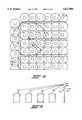
- FIG. 4schematically illustrates the operation of the meter reading system in a residential neighborhood wherein some modules are within range of the receiver and others are out of range.
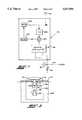
- FIG. 5illustrates a transit enable signal from the microprocessor, the output of the D/A converter and the oscillator RF output from the transmitter.
- FIG. 6illustrates a further embodiment of the present invention in which data concentrators are utilized to concentrate the flow of data from a plurality of meter modules.
- FIG. 7more fully discloses the phase lock loop used within each transmitter.
- FIG. 8discloses a further schematic diagram of a transmitter circuit for transmitting utility usage information at an accurate frequency which is particularly adapted to operate utilizing low power.
- FIG. 9illustrates an inductive loop mechanism for coupling the output of an environmentally sealed transmitter to an environmentally sealed antenna.
- Each of the meters 10-16is schematically disclosed located in a structure such as a house 11. While only four meters 10, 12, 14 and 16 have been disclosed, it should be realized that many more are utilized in an actual installation.
- Each of the utility meters 10-16has associated therewith a first means or meter module 20 which is adapted to provide a signal indicative of the utility usage at its associated utility meter.
- Each of the meter modules 20includes an antenna 22 which is operable to transmit a signal to an antenna 26 connected to a remote receiver 24. The receiver 24 then directs the signal to a utility usage registering device 28 which stores the utility usage information.
- the signal which is transmitted from the meter module 20 to the receiver 24is indicative of the utility usage at its associated utility meter.
- the signalalso can include information identifying the particular utility meter with which it is associated, information indicating whether the meter has been tampered with, leak detection information, and information indicating the peak usage, total utility usage, and time of use. If desired, other information could be sensed by the meter module 20 and transmitted to the receiver 24.
- the utility usage registering device 28is preferably a portable computer which receives the utility usage information, displays the information, and then stores the information.
- the receiver 24 and utility usage registering device 28are adapted to be portable and can be either handheld or located in a vehicle 30 for movement.
- Each of the meter modules 20transmits at a pseudo-random interval for a limited distance.
- the receiver 24will only receive signals from meter modules 20 which are within a finite range which is determined by the sensitivity of the receiver 24, the strength of the signals transmitted by the meter modules 20 and the RF propagation environment. Elevation, moisture in the atmosphere, location and interfering structures such as buildings, hills, etc. all affect the RF propagation environment.
- the receiver 24by controlling the sensitivity of the receiver, only a limited number of modules 20 are capable of transmitting signals which are received by the receiver 24 at any one time to minimize the probability of preventing the receiver 24 receiving simultaneous signals from multiple meter modules 20.
- the vehicle 30 which carries the receiver 24can be driven within range of the plurality of meter modules 20, and as the vehicle moves, the receiver 24 can sequentially receive signals from the plurality of meter modules 20 indicative of utility usage. Movement of the vehicle will bring some meter modules 20 into range and will allow others to become out of range so that only a finite number of modules 20 will transmit to the receiver 24 when the receiver is in a particular location.
- the meter module 20 disclosed in FIG. 2is particularly adapted to sense the utility usage of an associated electric meter 10 where a source of electric power is present, but can be utilized with other types of utility meters such as water or gas.
- the meter module disclosed in FIG. 8is battery powered to enable the meter module 20 to be utilized at locations in which electrical power is not present, such as in a gas or water meter.
- the use of a batteryrequires that the power drain by the meter module 20 be kept to a minimum to insure long battery life.
- the battery which provides the power supplycan be a 3.6 volt lithium battery.
- the meter module 20includes a pulser 34 which detects utility usage at the electric meter 10 and sends a signal over line 36 to a microprocessor 38.
- the pulser 34will send a pulse to the microprocessor every time the utility meter registers the use of a predetermined amount of the metered utility, for example, every 0.1 KW hour for an electric meter, or every cubic foot for a gas or water meter.
- the microprocessor 38includes a counter circuit (not illustrated) which is energized by the signal on line 36 to enable the microprocessor 38 to store therein utility usage information.
- an encoder or other meanscould be utilized to generate a serial data train to the microprocessor 38 which is indicative of utility usage.
- the microprocessor 38can also store therein information related to the utility meter 10 with which it is associated. For example, the microprocessor could store therein information related to the user's account number and the identity of the particular meter being read.
- An inductive coil 40is provided which can be sealed within the module 20 and which can have a signal induced therein which is directed along line 42 to the microprocessor 38 to program the microprocessor with information relative to the particular meter and user with which the microprocessor 38 and module 20 is associated.
- the pulser 34, inductive coil 40, and microprocessor 38can be similar to that disclosed in U.S. Pat. No. 4,463,354 entitled "Apparatus for Communicating Utility Usage Related Information from a Utility Usage Location to a Portable Utility Usage Registering Device", which patent is incorporated herein by reference.
- the microprocessor 38periodically directs a signal on line 44 to a digital to analog converter 46 which outputs the signal to the input 48 of a transmitter 50.
- the transmitter 50includes a crystal oscillator 52, a crystal 54, a varacter diode 56, and the antenna 22.
- the crystal 54oscillates at a predetermined frequency, and the varacter diode 56 can be utilized to tune the crystal oscillator 52 and crystal 54.
- the crystal oscillator 52 and related componentscan preferably be provided on a single synthesizer chip such as MC13176 manufactured by Motorola.
- a voltage controlled oscillator (VCO) phase lock loopcan be provided on the synthesizer chip to stabilize the output of the transmitter and allow the use of a low cost, stable, low frequency crystal 54 to generate a high frequency signal of identical stability.
- VCOvoltage controlled oscillator
- FIG. 7more fully discloses the transmitter 50.
- the transmitter 50includes a single synthesizer chip 98 to which data is inputted via the input 48 from the D/A converter.
- a crystal 54 and the varacter diode 56is connected to the chip 98 which includes the crystal oscillator 52 thereon.
- the chipalso includes the phase lock loop which includes a phase detector 100 to which the output of the crystal oscillator signal generator 52 is directed.
- the output of the phase detector 100is directed to a filter 102 whose output is directed to a voltage controlled oscillator 104.
- the output of the voltage controlled oscillator (VCO)is directed to the antenna 24 and back to a divide-by-N circuit 106.
- VCOvoltage controlled oscillator
- phase lock loopincluding the phase detector 100, filter 102, voltage controlled oscillator 104, and divide by N circuit 106, are all located within the synthesizer chip 98.
- the use of the phase lock loopallows the use of a stable low cost crystal to produce a stable output signal from the transmitter 50 which is important due to the very narrow frequency bands which are assigned by the FCC for utility usage transmission apparatus.
- the transmitter 50transmits a first signal indicative of utility usage information to the receiver 24 on an accurately controlled fixed frequency.
- the frequencymust be assigned by the FCC, is a very narrow frequency band, and must be accurately controlled so that the frequency does not wander into adjacent frequency bands.
- the crystal 54 and related componentsare temperature sensitive and vary in oscillating frequency when subjected to varying temperatures.
- the microprocessor 38establishes a signal on the input 48 of the transmitter 50, which signal is a temperature compensated signal to compensate for the varying temperature of the crystal 54 and related components to enable the crystal oscillator 52 to transmit at an accurately controlled fixed frequency.
- the signal at the input 48 of transmitter 50includes a first component which comprises a rapidly varying stepped voltage in a four-ary format for data transfer and a second component which comprises a slowly varying DC signal established by microprocessor 38 for temperature compensation of the transmitter 50.
- FIG. 5discloses the input to the transmitter 50 on line 48 as including a transmit enable signal 51 and the output from the D/A converter 46 as signal 53, which is arranged in a four-ary format.
- the enable signal 51 and the D/A outputare directed on line 48 to enable transmitter 50 and to effect a predetermined output from the oscillator circuit 52 which is illustrated at 55 in FIG. 5.
- the output from the oscillatoris also arranged in a four-ary format to establish four levels of FM modulation to transfer the utility usage information.
- the four-ary formatincludes four distinct input voltages, signals 53, necessary to transmit the utility usage information at the correct frequency from the transmitter 50 at the correct temperature.
- the four-ary format of the transmitted signalallows data compression and allows more information to be transmitted in a shorter period of time than if a binary signal were utilized.
- the microprocessor 38includes a look-up table therein which includes data indicative of the correct temperature compensated signal to be directed to the input 48 of the transmitter 50 to effect oscillation of the crystal 54 and output of transmitter 50 at each of the four frequencies of the four-ary format when the transmitter 50 and its related components are at various temperatures which have been entered into the look-up table.
- the transmitter 50is temperature compensated by the signal at input 48 from the microprocessor 38.
- a thermister 60is operable to sense the temperature of crystal 54 and transmitter 50 and establish a temperature signal on line 62 to an analog to digital converter 64 which directs the signal along line 66 to the microprocessor 38.
- the thermister 60provides a temperature signal to the microprocessor 38 which enables the microprocessor to determine from the look-up table therein the correct temperature compensated signal, dependent upon the actual sensed temperature of the transmitter 50, to be directed to the transmitter 50 to cause the transmitter 50 to transmit at an accurate predetermined frequency.
- the temperature compensated signalis in fact four temperature compensated signals to compensate the four-ary output of the transmitter 50.
- each individual module 20 including the transmitter 50, crystal 54, and thermister 60 associated therewithis "burned in" at varying temperatures so that each module 20 can be individually calibrated and the look-up table in each microprocessor 38 can be individually programmed with the correct data to establish the correct temperature compensated signal at the input to the transmitter 50 when the transmitter is at various temperatures.
- the temperature compensated signalcompensates for the nonlinearity of the thermister 60, crystal 54, and other components of the transmitter 50 which are burned in and calibrated as a unit.
- the individual calibration and compensation of each transmitter 50 and associated componentsallow for the use of lower cost components and crystals without degrading the accuracy of the transmitted signal.
- the microprocessor 38directs a first signal to transmitter 50 which causes transmitter 50 to transmit at a pseudo-random interval a first signal which is at an accurate fixed frequency, indicative of utility usage. Transmitting at a pseudo-random transmission interval prevents the receiver 24 receiving simultaneous overlapped transmission signals from a plurality of modules 20. A lock-up of transmission signals would occur when the receiver 24 receives transmissions from more than one module 20 which are equal in time and phase and by chance synchronized. Periodic transmission rather than constant transmission reduces the energy consumption of the module 20, allows same to be battery powered, and allows multiple modules 20 to transmit for short times which are spread out so as to enable the receiver to sequentially receive a plurality of signals from a plurality of modules without overlap of individual signals. Additionally, periodic transmissions are required by the F.C.C. in these transmission schemes.
- a clock 68can be provided to periodically generate a signal to tell microprocessor 38 not to transmit to prevent transmission of the first signal indicative of the utility usage.
- the use of clock 68minimizes energy drain when it is not desired for the transmitter 50 to transmit a signal indicative of utility usage. For example, if it is the utility's policy to only read the meters 10 during working hours, the clock 68 can be used to prevent transmissions during non-working hours, such as at night time. This further limits the energy usage of the module 20 and the drain of power from the battery 32. Additionally, the elimination of a receiver at the meter module 22, as is utilized in other prior art systems, further significantly reduces the energy consumption and cost of the meter module 20.
- FIG. 8discloses another embodiment of a transmitter circuit 50 which can be utilized when battery power is required.
- the transmitter circuit disclosed in FIG. 8is a low power transmitter and is particularly adapted to be powered by a switched battery such as at 108. If a 950.4 MHZ output is desired, which is a typical output for a preferred embodiment of the present invention, a 29.76 MHZ output from the oscillator can be inputted to the transmitter.
- Input datais directed along line 48 to a modified Butler tuned base emitter feed circuit.
- This circuit 110functions as a times 4 multiplier with a common emitter stage providing harmonic power to the collector.
- the output of the circuit 110would be 118.8 MHZ.
- This signalis directed through a common emitter coupling network 112 which couples the output of the circuit 110 to a second stage multiplier 114 which functions as a times 4 multiplier.
- the 118.8 MHZ input to the multiplier 114establishes a 475.2 MHZ output which is directed through a matching network 116 to a third stage multiplier 118 which is a times 2 multiplier.
- the output of the third stage multiplierwould be 950.4 MHZ and is directed to a common emitter coupling network 112 which directs the output thereof to a 1 milliwatt final amplifier 122.
- the output of the 1 milliwatt amplifier 122is 950.4 MHZ and is directed to a matching network, 124 and then to the antenna 22.
- the matching network 124may be coupled to the antenna 22 via a coupling loop 126.
- the use of an inductive loop coupler 126 between the transmitter 50 and the antennaenables the antenna structure to be an environmentally sealed rugged unit resistant to physical and environmental damage to the coupling network.
- the matching network 124 and transmitter 50can also be sealed when an inductive loop coupler is utilized to prevent physical and environmental damage thereto.
- FIG. 9more further illustrates the coupling of the antenna 26 to the output of the transmitter 50 via the inductive loop coupler 126.
- the inductive loop coupler 126can include a coil 128 disposed adjacent to a recess 136 in a sealed housing 134 in which the transmitter assembly and its associated electronics is located and a coil 130 disposed in a sealed structure 132 in which the antenna 26 is located.
- the coil 130is disposed in a projection 131 which matches the recess 136.
- the coil 130is brought into close proximity to the coil 128 by placing the projection 131 on the antenna structure 132 into the recess 136 on the housing 134 of transmitter assembly 50.
- the two-piece housing 134, 132is particularly adapted for use with pit set utility meters which are located in a pit 135.
- the electronics and transmitter 50 located in housing 134may be located in the pit and the antenna 22 and housing 134 may be located on the outside of the cover 137 which closes the pit.
- the projection 131can be received in an opening in the pit cover 137 to enable the projection 131 to be received in the recess 136 of housing 134 to couple coils 128 and 130.
- Such a structureenables the antenna 22 and housing 132 to be easily removed, replaced or serviced without opening the pit cover 137 and removing the electronics and transmitter. No physical connection is provided between housings 132 and 134 and each housing is completely sealed to provide a rugged structure which is resistant to physical damage.
- the meter module 20periodically transmits signals indicative of utility usage information at pseudo-random transmission intervals.
- the pseudo-random time interval between which the meter module 20 transmitsincludes a large fixed component FI (fixed internal) which is preset and a random component PI (pseudo-random interval) which is added to the preset fixed component to define the interval between transmissions which is equal to FI+PI (see FIG. 3).
- Informationcan be programmed into the inductive coil 40 to preset the large predetermined component FI of the pseudo-random transmission interval.
- the random small component PI which is added to the preset fixed component FI in the microprocessor 38is established by mathematically combining the fixed interval with the value of a continuously running counter (not illustrated) in the microprocessor 38 to generate a pseudo-random number which is used to set the pseudo-random transmission interval.
- the signals S from each module 20are periodically transmitted wherein the transmission interval between transmissions is pseudo random and equal to FI+PI.
- FIG. 3illustrates the signals transmitted by the meter modules 20 associated with utility meters 10, 12, 14 and 16. Each of the signals in FIG. 3 is transmitted at a fixed frequency controlled by the crystal 54 and each is transmitted at a pseudo-random transmission interval equal to FI+PI.
- the fixed component of the transmission interval FIis set at approximately 10 seconds and the pseudo-random interval PI is determined by the continuously running counter in the microprocessor.
- the pseudo-random intervalis much smaller than the fixed interval and is approximately from 5% to 15% of the duration of the fixed interval.
- the length of each signal Sis less than 10 milliseconds
- the fixed intervalis approximately 10 seconds
- the pseudo-random intervalis between 0.5 and 1.5 seconds.
- the pseudo-random interval PIvaries from transmission to transmission depending upon the number in the continuously running counter, not illustrated.
- each signal S transmitted by each meter module 20is small when compared to the pseudo-random transmission interval (FI+PI) between the periodic signals S. If two signals S are simultaneously received, the receiver 24 will disregard the simultaneous received signals and attempt to pick up the transmitted information when the next periodic signal is received from the meter module 20. If there is a 10 second transmission interval, the receiver will only have to wait an additional 10 seconds to receive the information. The pseudo-random transmission interval will prevent the next signals from being received simultaneously due to the fact that each pseudo-random transmission interval is different and random.
- FI+PIpseudo-random transmission interval
- CLASHwhich is the coincidence of transmissions from more than one meter module 20, will occur if two simultaneous signals are received by the receiver 24. CLASH can be minimized if the transmissions are short and the interval between transmissions are long.
- the likelihood of CLASHT transmit ⁇ T interval ⁇ number of units in range. For a typical installation, the transmission time (T transmit ) will be 5 ⁇ 10 -3 seconds and the time between transmissions (T interval ) will be approximately 10 seconds, with typically 50 meter modules 20 in range. Thus, the typical probability of CLASH will be 2.5 ⁇ 10 -2 . This would result in an average meter reading system reading 1,000 meters per day having perhaps 25 CLASHes per day.
- each meter module 20is typically in range for several transmissions, the receiver has multiple chances to receive the signal. If two signals are overlapped or CLASHed, the receiver will receive the two signals during the next transmission which will not be overlapped due to the pseudo-random transmission interval between sequential transmissions. By utilizing a random transmission interval, the meter modules 20 do not "lock in step” and continuous CLASH is minimized. Thus, one module might transmit once per 10.1 seconds and the next module might transmit once per 10.5 seconds. The pseudo-random transmission interval will vary from module to module and from one transmission to the next to minimize the likelihood of "in step" transmissions.
- a gain control 70can be connected to the receiver 24 to adjust the gain of the receiver, which adjusts its sensitivity or range. If too many signals from modules 20 are simultaneously received or CLASH is a frequent occurrence, such as might occur in a very dense installation of modules 20, such as in an apartment complex, the gain on the receiver can be adjusted to limit the number of signals received at one time and the range of the receiver 24. While the gain control 70 has been illustrated as being manually adjustable, automatic gain control could also be utilized which would provide gain control as a function of the average number of signals S received over a predetermined period of time. If a large number of signals S were received from a large number of modules 20, the gain control would automatically turn down the gain of the receiver 24.
- the transmission interval for each of the meter modules 20can be programmed into the microprocessor 38 via coil 40 at the time of installation and in a very dense installation the transmission interval can be increased to minimize CLASH.
- a one minute time intervalcould be utilized as the transmission interval. This would result in less CLASH.
- the receiver antenna 26is preferably polarized in a circular fashion while the antennas 22 on the transmitter 50 can be polarized either vertically or horizontally.
- the circular polarization on the receiver antenna 26increases its sensitivity, particularly when reflections of the signal transmitted from the modules 20 occur.
- a leak detection algorithmcan also be included in the microprocessor 38.
- Leak detectionis particularly advantageous for water meters and can be determined by checking water flow over a long time period to insure that there is at least one short period where no water or only a small amount of water is used. In a water installation it is assumed that there should be some periods where no or only a minimal amount of water is used, such as at night. If there are no short periods of minimal or low flow sensed over a long period such as a day or a week, it is assumed that there is a leak.
- the leak detectoris included in the microprocessor 38. The microprocessor senses and stores flow information from the pulser 34 and stores the sensed flow during a weekly time period which is divided into smaller time intervals.
- a leak signalis activated.
- the microprocessor 38can be utilized to determine the presence or absence of flow during each interval of the weekly period and includes the leakage information in the signal indicative of utility usage which is directed to transmitter 50.
- a tamper detecting circuit 72can be provided adjacent to meter 10 to provide an indication if the meter is tampered with.
- a tamper eventwould occur if the meter or the modules 20 were disconnected, moved, rendered ineffective, bypassed, or if other such unauthorized events occur.
- the tamper detector 72can include one or more of the following: a mechanical motion switch; a power failure sensor to sense if the meter was unplugged; and/or a magnetic sensor to determine if the meter was subjected to unusual magnetic fields.
- the tamper detector 72activates a counter in the microprocessor 38 which indexes every time a tamper event occurs. For example, if one tamper event occurs, the counter will read "1".
- the tamper detector 72provides a signal to the microprocessor 38 which is indicative of a tamper event and the counter in the microprocessor 38 keeps track of the tamper events.
- the indexed tamper signal from the microprocessor 38, along with the leak detection information,is included in the information in the signals transmitted from the transmitter 50 to the receiver 24. The receiver then loads the utility usage information, along with the tamper count and leakage information, into the personal computer 28.
- the personal computercan compare the tamper count sensed on the previous meter read with the tamper count sensed on the current meter read. If there is a difference in the tamper count, it will be indicative of the fact that a tamper event has been sensed by the tamper sensor 72. For example, if a meter was read and a tamper count of 1 was sensed, it could be an isolated event. If a month later the meter was again read and the tamper count was a 1, the utility could be reasonably sure that no tamper event had occurred.
- the tamper detecting circuit 72is particularly advantageous when a battery is used to power modules 20 as it does not have to be reset after a tamper event and does not require a receiver to effect reset of the tamper circuit 72 which would require additional energy draining circuitry.
- FIG. 4illustrates the sequential reading of a plurality of meters 10, 12, 14, 16, each of which has a module 20 associated therewith.
- Each of the metersis associated with a spaced apart location, such as a single family house.
- Each metertransmits a first signal indicative of utility usage, tamper events, and other information.
- Each signalhas a transmission range which is indicated at 80.
- the receiver 24has a reception range which is schematically illustrated at 82. From FIG. 3 it can be seen that only a limited number of a plurality of meters are read when the receiver 24 and vehicle 30 are in any one predetermined location. The number of meters read will be dependent on the range 82 of the receiver 24 and the range 80 of the transmitters 50 associated with the modules 20. Since the transmitters 50 transmit at transmission intervals which are long compared to the transmission period(s) of each of the modules 20, CLASH can be minimized as the receiver 24 and vehicle 30 move to sequentially read the plurality of meters.
- FIG. 6discloses a further embodiment of the invention wherein instead of utilizing a portable receiver, a fixed receiver 84 is utilized.
- the fixed receiver 84can be utilized to periodically receive transmissions from a plurality of modules 20.
- the fixed receiver 84includes an antenna 86 for receiving signals from the modules 20, and is connected via line 90 to a cable, optical or phone line or via a radio link over which the data can be transmitted from the receiver 84 to a utility usage registering device.
- the receiver 84acts as concentrator, and a plurality of receivers 84 can be located throughout a city to receive information from associated meter modules 20.
- the data from the plurality of meter modules 20can be transmitted to the concentrating receivers 84 which then either transmit the data via an antenna back to a central station, or transmit via phone or cable.
- a central stationinstead of a central station being utilized other substations could be utilized which would then further concentrate the data and forward it via radio, cable or phone to a central station.
- microprocessor 38has been disclosed as being programmed via a small coil 40, other manners of programming, such as an infra red signal or a direct connection, could be utilized.
- the coil 40has the advantage in that it can be sealed inside the meter module 20 so that no access is required for programming. This provides a more durable module by preventing a leak to the interior of the module via physical connector devices.
- the apparatusincludes a first means 20 adapted to be located at a utility meter 10 to provide a first signal indicative of utility usage information, transmitter means 50 responsive to the first signal for periodically transmitting at a pseudo-random transmission interval, a second signal which is indicative of utility usage information, receiver means 24 adapted to be located remote from the utility usage location for receiving the second signal, and a utility usage registering device 28 for storing the information in the second signal which is indicative of the utility usage.
- the transmitter 50is temperature compensated by the data in the microprocessor 38 lookup table to provide a temperature compensated signal to the transmitter 50.
- a tamper detector 72is associated with the first means 20 for detecting the occurrence of a tamper event and the tamper signal is indexed upon the tamper detector sensing the occurrence of a tamper event.
- an inductive loop 126is provided to couple the output of the transmitter 50 with the antenna 22.
Landscapes
- Physics & Mathematics (AREA)
- General Physics & Mathematics (AREA)
- Engineering & Computer Science (AREA)
- Computer Networks & Wireless Communication (AREA)
- Arrangements For Transmission Of Measured Signals (AREA)
Abstract
Description
Claims (9)
Priority Applications (1)
| Application Number | Priority Date | Filing Date | Title |
|---|---|---|---|
| US08/547,408US5617084A (en) | 1993-09-10 | 1995-10-24 | Apparatus for communicating utility usage-related information from a utility usage location to a utility usage registering device |
Applications Claiming Priority (2)
| Application Number | Priority Date | Filing Date | Title |
|---|---|---|---|
| US11998693A | 1993-09-10 | 1993-09-10 | |
| US08/547,408US5617084A (en) | 1993-09-10 | 1995-10-24 | Apparatus for communicating utility usage-related information from a utility usage location to a utility usage registering device |
Related Parent Applications (1)
| Application Number | Title | Priority Date | Filing Date |
|---|---|---|---|
| US11998693AContinuation | 1993-09-10 | 1993-09-10 |
Publications (1)
| Publication Number | Publication Date |
|---|---|
| US5617084Atrue US5617084A (en) | 1997-04-01 |
Family
ID=22387586
Family Applications (1)
| Application Number | Title | Priority Date | Filing Date |
|---|---|---|---|
| US08/547,408Expired - LifetimeUS5617084A (en) | 1993-09-10 | 1995-10-24 | Apparatus for communicating utility usage-related information from a utility usage location to a utility usage registering device |
Country Status (1)
| Country | Link |
|---|---|
| US (1) | US5617084A (en) |
Cited By (160)
| Publication number | Priority date | Publication date | Assignee | Title |
|---|---|---|---|---|
| US5719564A (en)* | 1996-05-10 | 1998-02-17 | Sears; Lawrence M. | Utility meter reading system |
| WO1998016070A1 (en)* | 1996-10-07 | 1998-04-16 | Amtech Corporation | Integrated multi-meter and wireless communication link |
| GB2326002A (en)* | 1997-06-06 | 1998-12-09 | Centrepoint Technology Limited | Remote reading of meters and sensors |
| US5850187A (en)* | 1996-03-27 | 1998-12-15 | Amtech Corporation | Integrated electronic tag reader and wireless communication link |
| GB2332546A (en)* | 1997-12-16 | 1999-06-23 | Atl Monitors Limited | Remote metering |
| WO1999013676A3 (en)* | 1997-09-12 | 1999-09-02 | Williams Wireless Inc | Wide area telemetry network |
| WO1999050933A1 (en)* | 1998-03-30 | 1999-10-07 | Motorola Inc. | Low power switched diversity antenna system |
| US5966055A (en)* | 1997-02-14 | 1999-10-12 | Lucent Technologies, Inc. | Phase-shift modulation of a direct antenna-driving VCO |
| US6015233A (en)* | 1997-12-22 | 2000-01-18 | Hti Technologies, Inc. | System for monitoring the temperature of a rotating devices |
| EP1028403A2 (en) | 1999-02-09 | 2000-08-16 | Ziegler, Horst Prof. Dr. | Data transmission system, especially for obtaining utility data |
| US6172608B1 (en)* | 1996-06-19 | 2001-01-09 | Integrated Silicon Design Pty. Ltd. | Enhanced range transponder system |
| GB2353142A (en)* | 1999-05-24 | 2001-02-14 | Atl Monitors Ltd | Communicating meter reading |
| US6208696B1 (en)* | 1997-10-07 | 2001-03-27 | Ramar Technology Limited | Low power density radio system |
| US6333975B1 (en) | 1998-03-03 | 2001-12-25 | Itron, Inc. | Method and system for reading intelligent utility meters |
| US20020024429A1 (en)* | 2000-08-25 | 2002-02-28 | Siegfried Kamlah | Anti-theft system for a motor vehicle and method for operating the anti-theft system |
| US6363335B1 (en) | 1999-09-20 | 2002-03-26 | Xircom Wireless, Inc. | Communications bridge for circuit switched data transfer simulation |
| US6377189B1 (en)* | 1999-03-31 | 2002-04-23 | Frederic M. Newman | Oil well servicing system |
| US20020077784A1 (en)* | 2000-05-03 | 2002-06-20 | Vock Curtis A. | Sensor and event system, and associated methods |
| US6411219B1 (en) | 1999-12-29 | 2002-06-25 | Siemens Power Transmission And Distribution, Inc. | Adaptive radio communication for a utility meter |
| US6456202B2 (en)* | 2000-04-21 | 2002-09-24 | Ecowater Systems, Inc. | System for monitoring the status of a water softener |
| EP1246501A2 (en) | 2001-03-28 | 2002-10-02 | Techem Service Aktiengesellschaft & Co. KG | Method and apparatus for reading of utility meters |
| EP1246500A2 (en) | 2001-03-28 | 2002-10-02 | Techem Service Aktiengesellschaft & Co. KG | Method for switching off temporarily not necessary functions of an electronic utility meter |
| US6483371B1 (en) | 2000-10-02 | 2002-11-19 | Northrop Grumman Corporation | Universal temperature compensation application specific integrated circuit |
| US20030016142A1 (en)* | 1999-08-16 | 2003-01-23 | Holmes John K. | Two-way wide area telemetry |
| US6559631B1 (en)* | 1998-04-10 | 2003-05-06 | General Electric Company | Temperature compensation for an electronic electricity meter |
| US6617976B2 (en)* | 1998-09-02 | 2003-09-09 | Neptune Technology Group, Inc. | Utility meter pit lid mounted antenna antenna assembly and method |
| US20030179714A1 (en)* | 2002-03-21 | 2003-09-25 | Gilgenbach Alan M. | Meter monitoring and tamper protection system and method |
| US20030196798A1 (en)* | 2001-09-05 | 2003-10-23 | Key Energy Services, Inc. | Method of monitoring service operations of a service vehicle at a well site |
| WO2001082028A3 (en)* | 2000-04-25 | 2003-12-11 | Airak Inc | System and method for distributed monitoring using remote sensors |
| US6670810B2 (en)* | 2000-04-25 | 2003-12-30 | Airak, Inc. | System and method for distributed monitoring of surroundings using telemetry of data from remote sensors |
| US20040001008A1 (en)* | 2002-06-27 | 2004-01-01 | Shuey Kenneth C. | Dynamic self-configuring metering network |
| US6677862B1 (en) | 1999-05-17 | 2004-01-13 | Schlumbergersema Inc. | Transmitter tolerant to crystal variations |
| US6684245B1 (en)* | 1997-04-08 | 2004-01-27 | Elster Electricity, Llc | Automatic meter reading system employing common broadcast command channel |
| US6697421B1 (en) | 1999-11-19 | 2004-02-24 | Intel Corporation | Operator independent, transparent wireless modem management |
| US20040113810A1 (en)* | 2002-06-28 | 2004-06-17 | Mason Robert T. | Data collector for an automated meter reading system |
| US20040201565A1 (en)* | 2003-04-09 | 2004-10-14 | Cunningham J. Vernon | Address and/or alarm indicator sign |
| US20040218616A1 (en)* | 1997-02-12 | 2004-11-04 | Elster Electricity, Llc | Remote access to electronic meters using a TCP/IP protocol suite |
| US6816480B1 (en)* | 1999-09-20 | 2004-11-09 | Intel Corporation | Data terminal apparatus |
| US6820049B1 (en) | 1999-09-20 | 2004-11-16 | Intel Corporation | Data collection system |
| US6844825B2 (en) | 2000-09-25 | 2005-01-18 | Ekstrom Industries, Inc. | Electric energy service apparatus with tamper detection |
| US20050030015A1 (en)* | 2003-07-22 | 2005-02-10 | Airak, Inc. | System and method for distributed monitoring of surroundings using telemetry of data from remote sensors |
| US20050059365A1 (en)* | 2003-09-15 | 2005-03-17 | Higgins Sidney Arch | Mounting bracket for a radio frequency communications device |
| US20050068749A1 (en)* | 2003-09-29 | 2005-03-31 | Funai Electric Co., Ltd. | Outer casing of electric equipment |
| US20050104744A1 (en)* | 1999-10-16 | 2005-05-19 | Tim Patterson | Automated meter reader device having optical sensor with automatic gain control |
| US20050110656A1 (en)* | 1999-10-16 | 2005-05-26 | Tim Patterson | Automated meter reader having high product delivery rate alert generator |
| US20050119930A1 (en)* | 2003-10-21 | 2005-06-02 | Itron, Inc. | Combined scheduling and management of work orders, such as for utility meter reading and utility servicing events |
| US20050122094A1 (en)* | 2003-10-03 | 2005-06-09 | Ekstrom Industries, Inc. | Modular watthour meter socket and test switch |
| US20050190066A1 (en)* | 2003-10-16 | 2005-09-01 | Mike Schleich | Consumptive leak detection system |
| US20050201397A1 (en)* | 1998-06-22 | 2005-09-15 | Statsignal Ipc, Llc | Systems and methods for monitoring conditions |
| US20050237221A1 (en)* | 2004-04-26 | 2005-10-27 | Brian Brent R | System and method for improved transmission of meter data |
| US20050240540A1 (en)* | 2004-04-26 | 2005-10-27 | Borleske Andrew J | System and method for efficient configuration in a fixed network automated meter reading system |
| US20050239414A1 (en)* | 2004-04-26 | 2005-10-27 | Mason Robert T Jr | Method and system for configurable qualification and registration in a fixed network automated meter reading system |
| US20050251403A1 (en)* | 2004-05-10 | 2005-11-10 | Elster Electricity, Llc. | Mesh AMR network interconnecting to TCP/IP wireless mesh network |
| US20050251401A1 (en)* | 2004-05-10 | 2005-11-10 | Elster Electricity, Llc. | Mesh AMR network interconnecting to mesh Wi-Fi network |
| US20050267898A1 (en)* | 2004-05-28 | 2005-12-01 | Robert Simon | Data format and method for communicating data associated with utility applications, such as for electric, gas, and water utility applications |
| US20050278440A1 (en)* | 2004-06-15 | 2005-12-15 | Elster Electricity, Llc. | System and method of visualizing network layout and performance characteristics in a wireless network |
| US20060022841A1 (en)* | 2004-07-28 | 2006-02-02 | Steve Hoiness | Mapping in mobile data collection systems, such as for utility meter reading and related applications |
| US20060028355A1 (en)* | 1999-10-16 | 2006-02-09 | Tim Patterson | Automated meter reader having peak product delivery rate generator |
| US20060069661A1 (en)* | 2004-09-24 | 2006-03-30 | Scoggins Sean M | System and method for automated configuration of meters |
| US20060074601A1 (en)* | 2004-10-01 | 2006-04-06 | Itron, Inc. | Endpoint location file format, such as for use in mapping endpoints in a utility meter reading system |
| US20060071811A1 (en)* | 2004-09-24 | 2006-04-06 | Christopher Russell G | System and method for creating multiple operating territories within a meter reading system |
| US20060071810A1 (en)* | 2004-09-24 | 2006-04-06 | Elster Electricity, Llc. | System for automatically enforcing a demand reset in a fixed network of electricity meters |
| US20060072465A1 (en)* | 2004-09-24 | 2006-04-06 | Scoggins Sean M | System for automated management of spontaneous node migration in a distributed fixed wireless network |
| US20060135119A1 (en)* | 2004-12-22 | 2006-06-22 | Navaneet Kumar | System and method of providing a geographic view of nodes in a wireless network |
| US20060161473A1 (en)* | 1998-03-19 | 2006-07-20 | Defosse Erin M | Remote data acquisition, transmission and analysis system including handheld wireless equipment |
| US20060167967A1 (en)* | 1998-03-19 | 2006-07-27 | Defosse Erin M | System and method for monitoring and control of beverage dispensing equipment |
| US20060206433A1 (en)* | 2005-03-11 | 2006-09-14 | Elster Electricity, Llc. | Secure and authenticated delivery of data from an automated meter reading system |
| US20060224335A1 (en)* | 2005-03-29 | 2006-10-05 | Elster Electricity, Llc | Collecting interval data from a relative time battery powered automated meter reading devices |
| US20070018852A1 (en)* | 2005-07-19 | 2007-01-25 | Seitz Shane M | Power load pattern monitoring system |
| US20070043849A1 (en)* | 2003-09-05 | 2007-02-22 | David Lill | Field data collection and processing system, such as for electric, gas, and water utility data |
| US20070050465A1 (en)* | 1998-03-19 | 2007-03-01 | Canter James M | Packet capture agent for use in field assets employing shared bus architecture |
| US20070053519A1 (en)* | 2005-08-30 | 2007-03-08 | Godwin Bryan W | Wireless adapter for data exchange and method |
| US20070057813A1 (en)* | 2005-09-09 | 2007-03-15 | Cahill-O'brien Barry | RF meter reading network with wake-up tone calibrated endpoints |
| US20070063868A1 (en)* | 2005-09-02 | 2007-03-22 | Elster Electricity, Llc | Multipurpose interface for an automated meter reading device |
| US7197330B1 (en) | 2000-03-14 | 2007-03-27 | Intel Corporation | Dual port wireless modem for circuit switched and packet switched data transfer |
| US20070073866A1 (en)* | 2005-09-28 | 2007-03-29 | Elster Electricity, Llc | Ensuring automatic season change demand resets in a mesh type network of telemetry devices |
| US20070103335A1 (en)* | 2005-10-20 | 2007-05-10 | Fitzgerald Aaron J | Automatic detection of unusual consumption by a utility meter |
| US20070111753A1 (en)* | 2000-12-15 | 2007-05-17 | Vock Curtis A | Personal items network, and associated methods |
| US20070112907A1 (en)* | 1998-03-19 | 2007-05-17 | Defosse Erin M | Remote Data Acquisition, Transmission And Analysis System Including Handheld Wireless Equipment |
| US20070135972A1 (en)* | 2005-10-07 | 2007-06-14 | Jay Jacobson | Method and system for improving the efficiency and reliability of a power grid |
| US20070147268A1 (en)* | 2005-12-23 | 2007-06-28 | Elster Electricity, Llc | Distributing overall control of mesh AMR LAN networks to WAN interconnected collectors |
| US20070200729A1 (en)* | 2006-02-16 | 2007-08-30 | Elster Electricity, Llc | In-home display that communicates with a fixed network meter reading system |
| US20070205915A1 (en)* | 2006-02-16 | 2007-09-06 | Elster Electricty, Llc | Load control unit in communication with a fixed network meter reading system |
| US20070208530A1 (en)* | 1994-11-21 | 2007-09-06 | Vock Curtis A | Activity monitoring systems & methods |
| US20070211768A1 (en)* | 2006-02-03 | 2007-09-13 | Mark Cornwall | Versatile radio packeting for automatic meter reading systems |
| US20070247331A1 (en)* | 2006-03-31 | 2007-10-25 | Bruce Angelis | Integrated data collection, anomaly detection and investigation, such as integrated mobile utility meter reading, theft detection and investigation system |
| US20070247789A1 (en)* | 2006-03-31 | 2007-10-25 | Eric Benson | Data analysis system, such as a theft scenario analysis system for automated utility metering |
| US20070270721A1 (en)* | 2006-05-22 | 2007-11-22 | Apple Computer, Inc. | Calibration techniques for activity sensing devices |
| US7308370B2 (en) | 2005-03-22 | 2007-12-11 | Elster Electricity Llc | Using a fixed network wireless data collection system to improve utility responsiveness to power outages |
| US20080024320A1 (en)* | 1999-02-23 | 2008-01-31 | Ehrke Lance A | Electronic electric meter for networked meter reading |
| US20080062005A1 (en)* | 2006-08-08 | 2008-03-13 | Badger Meter, Inc. | AMR transmitter with programmable operating mode parameters |
| US20080074283A1 (en)* | 2006-09-25 | 2008-03-27 | Jeff Verkleeren | Utility meter antenna for ground mounted meter boxes |
| US20080129538A1 (en)* | 1999-02-23 | 2008-06-05 | Raj Vaswani | Electronic electric meter for networked meter reading |
| US20080144548A1 (en)* | 2006-12-14 | 2008-06-19 | Elster Electricity, Llc | Optimization of redundancy and throughput in an automated meter data collection system using a wireless network |
| US20080180274A1 (en)* | 2004-01-14 | 2008-07-31 | Itron, Inc. | Method and apparatus for collecting and displaying consumption data a from a meter reading system |
| US20080186200A1 (en)* | 2007-02-02 | 2008-08-07 | Kelly Laughlin-Parker | High power AMR transmitter with data profiling |
| US20080186898A1 (en)* | 2005-01-25 | 2008-08-07 | Sipco, Llc | Wireless Network Protocol System And Methods |
| US20080259844A1 (en)* | 2007-04-20 | 2008-10-23 | Elster Electricity, Llc | Over the air microcontroller flash memory updates |
| US20080266761A1 (en)* | 2007-04-24 | 2008-10-30 | Ekstrom Industries, Inc. | Lock ring for a watthour meter application |
| US20080294452A1 (en)* | 2006-08-31 | 2008-11-27 | Stephen Gregory Hunt | Managing Supply of a Utility to a Customer Premises |
| US20090091977A1 (en)* | 2007-10-04 | 2009-04-09 | Arc Innovations Limited | Method and system for updating a stored data value in a non-volatile memory |
| US20090267783A1 (en)* | 2005-10-18 | 2009-10-29 | Apple Inc. | Shoe Wear-Out Sensor, Body-Bar Sensing System, Unitless Activity Assessment and Associated Methods |
| US20090284392A1 (en)* | 2007-01-11 | 2009-11-19 | Innovative Technology Concepts, Inc. | Remotely readable gas meter and method of using the same |
| US20090309756A1 (en)* | 2008-06-13 | 2009-12-17 | Elster Electricity, Llc | Techniques For Limiting Demand From An electricity Meter With An Installed Relay |
| US7639157B1 (en) | 1998-03-24 | 2009-12-29 | At&T Intellectual Property, I,L.P. | Wireless telemetry methods and systems for communicating with or controlling intelligent devices |
| US7643895B2 (en) | 2006-05-22 | 2010-01-05 | Apple Inc. | Portable media device with workout support |
| US7698101B2 (en) | 2007-03-07 | 2010-04-13 | Apple Inc. | Smart garment |
| US20100110617A1 (en)* | 2001-11-26 | 2010-05-06 | Itron, Inc. | Embedded antenna apparatus for utility metering applications |
| US20100117856A1 (en)* | 2008-11-11 | 2010-05-13 | Itron, Inc. | System and method of high volume import, validation and estimation of meter data |
| US20100156632A1 (en)* | 2008-10-27 | 2010-06-24 | Mueller International, Inc. | Infrastructure monitoring system and method |
| US20100188263A1 (en)* | 2009-01-29 | 2010-07-29 | Itron, Inc. | Prioritized collection of meter readings |
| US7774624B2 (en)* | 2000-01-24 | 2010-08-10 | Micro Motion, Inc. | System for preventing tampering with a signal conditioner remote from a host system |
| US7813715B2 (en) | 2006-08-30 | 2010-10-12 | Apple Inc. | Automated pairing of wireless accessories with host devices |
| WO2010118171A1 (en)* | 2009-04-07 | 2010-10-14 | Rf Savvy Llc | Smart meter cover with integral, untethered antenna elements for ami communications |
| US20100265095A1 (en)* | 2009-04-20 | 2010-10-21 | Itron, Inc. | Endpoint classification and command processing |
| US20100295672A1 (en)* | 2009-05-22 | 2010-11-25 | Mueller International, Inc. | Infrastructure monitoring devices, systems, and methods |
| US7913297B2 (en) | 2006-08-30 | 2011-03-22 | Apple Inc. | Pairing of wireless devices using a wired medium |
| US20110115682A1 (en)* | 2006-09-15 | 2011-05-19 | Itron, Inc. | Rf local area network antenna design |
| US20110193569A1 (en)* | 2010-02-11 | 2011-08-11 | Landis+Gyr, Inc. | Oscillator Circuit with RF Suppression |
| US8000314B2 (en) | 1996-12-06 | 2011-08-16 | Ipco, Llc | Wireless network system and method for providing same |
| US8013732B2 (en) | 1998-06-22 | 2011-09-06 | Sipco, Llc | Systems and methods for monitoring and controlling remote devices |
| US8031650B2 (en) | 2004-03-03 | 2011-10-04 | Sipco, Llc | System and method for monitoring remote devices with a dual-mode wireless communication protocol |
| US8073984B2 (en) | 2006-05-22 | 2011-12-06 | Apple Inc. | Communication protocol for use with portable electronic devices |
| US8171136B2 (en) | 2001-10-30 | 2012-05-01 | Sipco, Llc | System and method for transmitting pollution information over an integrated wireless network |
| WO2012075063A1 (en)* | 2010-12-02 | 2012-06-07 | Aclara Power-Line Systems Inc. | Mains-synchronous power-line communications system and method |
| US8203463B2 (en) | 2009-02-13 | 2012-06-19 | Elster Electricity Llc | Wakeup and interrogation of meter-reading devices using licensed narrowband and unlicensed wideband radio communication |
| US8330669B2 (en) | 2010-04-22 | 2012-12-11 | Itron, Inc. | Remote antenna coupling in an AMR device |
| US8350717B2 (en) | 2006-06-05 | 2013-01-08 | Neptune Technology Group, Inc. | Fixed network for an automatic utility meter reading system |
| US20130045730A1 (en)* | 2010-02-03 | 2013-02-21 | Rtx A/S | Programming of a dect/cat-iq communication device |
| US8407333B2 (en) | 2002-11-18 | 2013-03-26 | Mueller International, Llc | Method and apparatus for inexpensively monitoring and controlling remotely distributed appliances |
| US8410931B2 (en) | 1998-06-22 | 2013-04-02 | Sipco, Llc | Mobile inventory unit monitoring systems and methods |
| US8446884B2 (en) | 2004-03-03 | 2013-05-21 | Sipco, Llc | Dual-mode communication devices, methods and systems |
| US8489063B2 (en) | 2001-10-24 | 2013-07-16 | Sipco, Llc | Systems and methods for providing emergency messages to a mobile device |
| US20140049404A1 (en)* | 2011-02-25 | 2014-02-20 | Yuri Giuseppe Rassega | Handheld device for detecting tampering aimed to modify the metering of measure-deliverable goods or services and inspection method |
| US8660134B2 (en) | 2011-10-27 | 2014-02-25 | Mueller International, Llc | Systems and methods for time-based hailing of radio frequency devices |
| US8666357B2 (en) | 2001-10-24 | 2014-03-04 | Sipco, Llc | System and method for transmitting an emergency message over an integrated wireless network |
| US8787246B2 (en) | 2009-02-03 | 2014-07-22 | Ipco, Llc | Systems and methods for facilitating wireless network communication, satellite-based wireless network systems, and aircraft-based wireless network systems, and related methods |
| US8833390B2 (en) | 2011-05-31 | 2014-09-16 | Mueller International, Llc | Valve meter assembly and method |
| US8855569B2 (en) | 2011-10-27 | 2014-10-07 | Mueller International, Llc | Systems and methods for dynamic squelching in radio frequency devices |
| US8924588B2 (en) | 1999-03-18 | 2014-12-30 | Sipco, Llc | Systems and methods for controlling communication between a host computer and communication devices |
| US8928170B2 (en) | 2010-08-13 | 2015-01-06 | Aclara Technologies Llc | Digital two way automatic communication system (TWACS) outbound receiver and method |
| US8931505B2 (en) | 2010-06-16 | 2015-01-13 | Gregory E. HYLAND | Infrastructure monitoring devices, systems, and methods |
| US8964708B2 (en) | 1998-06-22 | 2015-02-24 | Sipco Llc | Systems and methods for monitoring and controlling remote devices |
| US20150324604A1 (en)* | 2014-05-09 | 2015-11-12 | Fujitsu Limited | Trusted and privacy-preserving mechanism for electricity usage data disclosure using verifiable noise |
| JP2016017761A (en)* | 2014-07-04 | 2016-02-01 | 富士通株式会社 | Quartz crystal resonator and crystal resonator characteristic measuring method |
| US9294147B2 (en) | 2013-10-01 | 2016-03-22 | Aclara Technologies Llc | TWACS transmitter and receiver |
| US9494249B2 (en) | 2014-05-09 | 2016-11-15 | Mueller International, Llc | Mechanical stop for actuator and orifice |
| US9565620B2 (en) | 2014-09-02 | 2017-02-07 | Mueller International, Llc | Dynamic routing in a mesh network |
| US9612132B2 (en) | 2007-12-26 | 2017-04-04 | Elster Solutions, Llc | Optimized data collection in a wireless fixed network metering system |
| EP1393281B1 (en)* | 2001-05-04 | 2017-11-22 | Invensys Metering Systems/North America Inc. | System and method for communicating and control of automated meter readings |
| US9868041B2 (en) | 2006-05-22 | 2018-01-16 | Apple, Inc. | Integrated media jukebox and physiologic data handling application |
| US20180212609A1 (en)* | 2017-01-24 | 2018-07-26 | Seiko Epson Corporation | Circuit device, oscillator, physical quantity measurement device, electronic apparatus, and vehicle |
| US10180414B2 (en) | 2013-03-15 | 2019-01-15 | Mueller International, Llc | Systems for measuring properties of water in a water distribution system |
| US10276939B1 (en) | 2017-11-28 | 2019-04-30 | Mueller International, Llc | Through-the-lid pit antenna |
| US20190271575A1 (en)* | 2001-03-09 | 2019-09-05 | Arad Measuring Technologies Ltd. | Meter Register |
| US10985928B2 (en) | 2017-01-24 | 2021-04-20 | Seiko Epson Corporation | Circuit device, oscillation device, physical quantity measuring device, electronic apparatus, and vehicle |
| US11031938B2 (en)* | 2019-10-25 | 2021-06-08 | Cisco Technology, Inc. | Radio frequency synchronization in low-power and lossy networks |
| US11041839B2 (en) | 2015-06-05 | 2021-06-22 | Mueller International, Llc | Distribution system monitoring |
| US11681833B2 (en) | 2016-08-29 | 2023-06-20 | Block, Inc. | Secure electronic circuitry with tamper detection |
| US11725366B2 (en) | 2020-07-16 | 2023-08-15 | Mueller International, Llc | Remote-operated flushing system |
Citations (25)
| Publication number | Priority date | Publication date | Assignee | Title |
|---|---|---|---|---|
| US2962702A (en)* | 1956-02-20 | 1960-11-29 | Westinghouse Electric Corp | Remote metering |
| US3114900A (en)* | 1960-12-08 | 1963-12-17 | Gen Electric | Automatic incremental metering |
| US3588825A (en)* | 1968-10-02 | 1971-06-28 | Gen Signal Corp | Digital commaless code remote control system |
| US3656112A (en)* | 1969-03-14 | 1972-04-11 | Constellation Science And Tech | Utility meter remote automatic reading system |
| US3705385A (en)* | 1969-12-10 | 1972-12-05 | Northern Illinois Gas Co | Remote meter reading system |
| US4057785A (en)* | 1975-03-14 | 1977-11-08 | Westinghouse Electric Corporation | Sequence of events recorder and system for transmitting sequence data from a remote station to a master station |
| US4119948A (en)* | 1976-04-29 | 1978-10-10 | Ernest Michael Ward | Remote meter reading system |
| US4254472A (en)* | 1978-08-14 | 1981-03-03 | The Valeron Corporation | Remote metering system |
| US4396915A (en)* | 1980-03-31 | 1983-08-02 | General Electric Company | Automatic meter reading and control system |
| US4408204A (en)* | 1980-08-06 | 1983-10-04 | Midwest Computer Register Corp. | Digital counter/transmitter with remote receiver/display |
| US4463354A (en)* | 1981-12-09 | 1984-07-31 | Sears Lawrence M | Apparatus for communicating utility usage related information from a utility usage location to a portable utility usage registering device |
| US4504831A (en)* | 1981-10-09 | 1985-03-12 | Systems And Support, Incorporated | Utility usage data and event data acquisition system |
| US4614945A (en)* | 1985-02-20 | 1986-09-30 | Diversified Energies, Inc. | Automatic/remote RF instrument reading method and apparatus |
| US4685149A (en)* | 1977-07-29 | 1987-08-04 | Rockwell International Corporation | Meteor scatter burst communication system |
| US4799059A (en)* | 1986-03-14 | 1989-01-17 | Enscan, Inc. | Automatic/remote RF instrument monitoring system |
| US4850010A (en)* | 1985-11-25 | 1989-07-18 | Alcatel N.V. | Telemetry terminal |
| US4878236A (en)* | 1988-12-02 | 1989-10-31 | Ray Donald K | Automatic emergency locator system and method |
| US4940976A (en)* | 1988-02-05 | 1990-07-10 | Utilicom Inc. | Automated remote water meter readout system |
| US5056107A (en)* | 1990-02-15 | 1991-10-08 | Iris Systems Inc. | Radio communication network for remote data generating stations |
| US5086292A (en)* | 1989-10-31 | 1992-02-04 | Iris Systems Inc. | Tamper detection device for utility meter |
| US5194860A (en)* | 1989-11-16 | 1993-03-16 | The General Electric Company, P.L.C. | Radio telemetry systems with channel selection |
| US5432507A (en)* | 1992-10-27 | 1995-07-11 | Societa' Italiana Per Il Gas P.A. | Method and network for operating a distribution network |
| US5438329A (en)* | 1993-06-04 | 1995-08-01 | M & Fc Holding Company, Inc. | Duplex bi-directional multi-mode remote instrument reading and telemetry system |
| US5448230A (en)* | 1993-06-25 | 1995-09-05 | Metscan, Incorporated | Remote data acquisition and communication system |
| US5488565A (en)* | 1993-05-28 | 1996-01-30 | Abb Power T&D Company Inc. | Tamper detection methods and apparatus for load management terminals |
- 1995
- 1995-10-24USUS08/547,408patent/US5617084A/ennot_activeExpired - Lifetime
Patent Citations (25)
| Publication number | Priority date | Publication date | Assignee | Title |
|---|---|---|---|---|
| US2962702A (en)* | 1956-02-20 | 1960-11-29 | Westinghouse Electric Corp | Remote metering |
| US3114900A (en)* | 1960-12-08 | 1963-12-17 | Gen Electric | Automatic incremental metering |
| US3588825A (en)* | 1968-10-02 | 1971-06-28 | Gen Signal Corp | Digital commaless code remote control system |
| US3656112A (en)* | 1969-03-14 | 1972-04-11 | Constellation Science And Tech | Utility meter remote automatic reading system |
| US3705385A (en)* | 1969-12-10 | 1972-12-05 | Northern Illinois Gas Co | Remote meter reading system |
| US4057785A (en)* | 1975-03-14 | 1977-11-08 | Westinghouse Electric Corporation | Sequence of events recorder and system for transmitting sequence data from a remote station to a master station |
| US4119948A (en)* | 1976-04-29 | 1978-10-10 | Ernest Michael Ward | Remote meter reading system |
| US4685149A (en)* | 1977-07-29 | 1987-08-04 | Rockwell International Corporation | Meteor scatter burst communication system |
| US4254472A (en)* | 1978-08-14 | 1981-03-03 | The Valeron Corporation | Remote metering system |
| US4396915A (en)* | 1980-03-31 | 1983-08-02 | General Electric Company | Automatic meter reading and control system |
| US4408204A (en)* | 1980-08-06 | 1983-10-04 | Midwest Computer Register Corp. | Digital counter/transmitter with remote receiver/display |
| US4504831A (en)* | 1981-10-09 | 1985-03-12 | Systems And Support, Incorporated | Utility usage data and event data acquisition system |
| US4463354A (en)* | 1981-12-09 | 1984-07-31 | Sears Lawrence M | Apparatus for communicating utility usage related information from a utility usage location to a portable utility usage registering device |
| US4614945A (en)* | 1985-02-20 | 1986-09-30 | Diversified Energies, Inc. | Automatic/remote RF instrument reading method and apparatus |
| US4850010A (en)* | 1985-11-25 | 1989-07-18 | Alcatel N.V. | Telemetry terminal |
| US4799059A (en)* | 1986-03-14 | 1989-01-17 | Enscan, Inc. | Automatic/remote RF instrument monitoring system |
| US4940976A (en)* | 1988-02-05 | 1990-07-10 | Utilicom Inc. | Automated remote water meter readout system |
| US4878236A (en)* | 1988-12-02 | 1989-10-31 | Ray Donald K | Automatic emergency locator system and method |
| US5086292A (en)* | 1989-10-31 | 1992-02-04 | Iris Systems Inc. | Tamper detection device for utility meter |
| US5194860A (en)* | 1989-11-16 | 1993-03-16 | The General Electric Company, P.L.C. | Radio telemetry systems with channel selection |
| US5056107A (en)* | 1990-02-15 | 1991-10-08 | Iris Systems Inc. | Radio communication network for remote data generating stations |
| US5432507A (en)* | 1992-10-27 | 1995-07-11 | Societa' Italiana Per Il Gas P.A. | Method and network for operating a distribution network |
| US5488565A (en)* | 1993-05-28 | 1996-01-30 | Abb Power T&D Company Inc. | Tamper detection methods and apparatus for load management terminals |
| US5438329A (en)* | 1993-06-04 | 1995-08-01 | M & Fc Holding Company, Inc. | Duplex bi-directional multi-mode remote instrument reading and telemetry system |
| US5448230A (en)* | 1993-06-25 | 1995-09-05 | Metscan, Incorporated | Remote data acquisition and communication system |
Non-Patent Citations (12)
| Title |
|---|
| American Meter Company, "Information on Trace Automated Systems," 1990. |
| American Meter Company, Information on Trace Automated Systems, 1990.* |
| Datamatic, Inc., "Walk-By," Jul. 1990. |
| Datamatic, Inc., Walk By, Jul. 1990.* |
| IDSystems, "Nonstop Meter Reading," Jan. 1993. |
| IDSystems, Nonstop Meter Reading, Jan. 1993.* |
| Schlumberger Industries, "ProRadio Remote Meter Reading Systems," May 1993. |
| Schlumberger Industries, ProRadio Remote Meter Reading Systems, May 1993.* |
| Technopress Ltd., "Meter Reading Information," copyright 1989, pp. 69-82. |
| Technopress Ltd., Meter Reading Information, copyright 1989, pp. 69 82.* |
| Water and Waste Digest, "Here's How It Works," May-Jun. 1993. |
| Water and Waste Digest, Here s How It Works, May Jun. 1993.* |
Cited By (312)
| Publication number | Priority date | Publication date | Assignee | Title |
|---|---|---|---|---|
| US8352211B2 (en) | 1994-11-21 | 2013-01-08 | Apple Inc. | Activity monitoring systems and methods |
| US8036851B2 (en) | 1994-11-21 | 2011-10-11 | Apple Inc. | Activity monitoring systems and methods |
| US20090150114A1 (en)* | 1994-11-21 | 2009-06-11 | Apple Inc. | Activity monitoring systems and methods |
| US7512515B2 (en) | 1994-11-21 | 2009-03-31 | Apple Inc. | Activity monitoring systems and methods |
| US7451056B2 (en) | 1994-11-21 | 2008-11-11 | Phatrat Technology, Llc | Activity monitoring systems and methods |
| US20070208530A1 (en)* | 1994-11-21 | 2007-09-06 | Vock Curtis A | Activity monitoring systems & methods |
| US6078251A (en)* | 1996-03-27 | 2000-06-20 | Intermec Ip Corporation | Integrated multi-meter and wireless communication link |
| US5850187A (en)* | 1996-03-27 | 1998-12-15 | Amtech Corporation | Integrated electronic tag reader and wireless communication link |
| US5719564A (en)* | 1996-05-10 | 1998-02-17 | Sears; Lawrence M. | Utility meter reading system |
| US6172608B1 (en)* | 1996-06-19 | 2001-01-09 | Integrated Silicon Design Pty. Ltd. | Enhanced range transponder system |
| WO1998016070A1 (en)* | 1996-10-07 | 1998-04-16 | Amtech Corporation | Integrated multi-meter and wireless communication link |
| US8982856B2 (en) | 1996-12-06 | 2015-03-17 | Ipco, Llc | Systems and methods for facilitating wireless network communication, satellite-based wireless network systems, and aircraft-based wireless network systems, and related methods |
| US8000314B2 (en) | 1996-12-06 | 2011-08-16 | Ipco, Llc | Wireless network system and method for providing same |
| US8625496B2 (en) | 1996-12-06 | 2014-01-07 | Ipco, Llc | Wireless network system and method for providing same |
| US8233471B2 (en) | 1996-12-06 | 2012-07-31 | Ipco, Llc | Wireless network system and method for providing same |
| US7126494B2 (en) | 1997-02-12 | 2006-10-24 | Elster Electricity, Llc | Remote access to electronic meters using a TCP/IP protocol suite |
| US20040218616A1 (en)* | 1997-02-12 | 2004-11-04 | Elster Electricity, Llc | Remote access to electronic meters using a TCP/IP protocol suite |
| US5966055A (en)* | 1997-02-14 | 1999-10-12 | Lucent Technologies, Inc. | Phase-shift modulation of a direct antenna-driving VCO |
| US6684245B1 (en)* | 1997-04-08 | 2004-01-27 | Elster Electricity, Llc | Automatic meter reading system employing common broadcast command channel |
| US20040210544A1 (en)* | 1997-04-08 | 2004-10-21 | Shuey Kenneth C | Broadcast technology for an automatic meter reading system |
| GB2326002A (en)* | 1997-06-06 | 1998-12-09 | Centrepoint Technology Limited | Remote reading of meters and sensors |
| US20100141474A1 (en)* | 1997-09-05 | 2010-06-10 | Ehrke Lance A | Electronic electric meter for networked meter reading |
| WO1999013676A3 (en)* | 1997-09-12 | 1999-09-02 | Williams Wireless Inc | Wide area telemetry network |
| US6124806A (en)* | 1997-09-12 | 2000-09-26 | Williams Wireless, Inc. | Wide area remote telemetry |
| US6366217B1 (en) | 1997-09-12 | 2002-04-02 | Internet Telemetry Corp. | Wide area remote telemetry |
| US6208696B1 (en)* | 1997-10-07 | 2001-03-27 | Ramar Technology Limited | Low power density radio system |
| GB2332546A (en)* | 1997-12-16 | 1999-06-23 | Atl Monitors Limited | Remote metering |
| US6015233A (en)* | 1997-12-22 | 2000-01-18 | Hti Technologies, Inc. | System for monitoring the temperature of a rotating devices |
| US6333975B1 (en) | 1998-03-03 | 2001-12-25 | Itron, Inc. | Method and system for reading intelligent utility meters |
| US20060161473A1 (en)* | 1998-03-19 | 2006-07-20 | Defosse Erin M | Remote data acquisition, transmission and analysis system including handheld wireless equipment |
| US20060167967A1 (en)* | 1998-03-19 | 2006-07-27 | Defosse Erin M | System and method for monitoring and control of beverage dispensing equipment |
| US8631093B2 (en) | 1998-03-19 | 2014-01-14 | Crane Merchandising Systems, Inc. | Remote data acquisition, transmission and analysis system including handheld wireless equipment |
| US20070050465A1 (en)* | 1998-03-19 | 2007-03-01 | Canter James M | Packet capture agent for use in field assets employing shared bus architecture |
| US20070112907A1 (en)* | 1998-03-19 | 2007-05-17 | Defosse Erin M | Remote Data Acquisition, Transmission And Analysis System Including Handheld Wireless Equipment |
| US7639157B1 (en) | 1998-03-24 | 2009-12-29 | At&T Intellectual Property, I,L.P. | Wireless telemetry methods and systems for communicating with or controlling intelligent devices |
| WO1999050933A1 (en)* | 1998-03-30 | 1999-10-07 | Motorola Inc. | Low power switched diversity antenna system |
| US5999138A (en)* | 1998-03-30 | 1999-12-07 | Ponce De Leon; Lorenzo A. | Low power switched diversity antenna system |
| US6559631B1 (en)* | 1998-04-10 | 2003-05-06 | General Electric Company | Temperature compensation for an electronic electricity meter |
| US9430936B2 (en) | 1998-06-22 | 2016-08-30 | Sipco Llc | Systems and methods for monitoring and controlling remote devices |
| US8064412B2 (en) | 1998-06-22 | 2011-11-22 | Sipco, Llc | Systems and methods for monitoring conditions |
| US8223010B2 (en) | 1998-06-22 | 2012-07-17 | Sipco Llc | Systems and methods for monitoring vehicle parking |
| US9571582B2 (en) | 1998-06-22 | 2017-02-14 | Sipco, Llc | Systems and methods for monitoring and controlling remote devices |
| US8212667B2 (en) | 1998-06-22 | 2012-07-03 | Sipco, Llc | Automotive diagnostic data monitoring systems and methods |
| US8964708B2 (en) | 1998-06-22 | 2015-02-24 | Sipco Llc | Systems and methods for monitoring and controlling remote devices |
| US8410931B2 (en) | 1998-06-22 | 2013-04-02 | Sipco, Llc | Mobile inventory unit monitoring systems and methods |
| US20050201397A1 (en)* | 1998-06-22 | 2005-09-15 | Statsignal Ipc, Llc | Systems and methods for monitoring conditions |
| US9129497B2 (en) | 1998-06-22 | 2015-09-08 | Statsignal Systems, Inc. | Systems and methods for monitoring conditions |
| US8013732B2 (en) | 1998-06-22 | 2011-09-06 | Sipco, Llc | Systems and methods for monitoring and controlling remote devices |
| US9691263B2 (en) | 1998-06-22 | 2017-06-27 | Sipco, Llc | Systems and methods for monitoring conditions |
| US6617976B2 (en)* | 1998-09-02 | 2003-09-09 | Neptune Technology Group, Inc. | Utility meter pit lid mounted antenna antenna assembly and method |
| EP1028403A3 (en)* | 1999-02-09 | 2005-05-04 | Ziegler, Horst Prof. Dr. | Data transmission system, especially for obtaining utility data |
| EP1028403A2 (en) | 1999-02-09 | 2000-08-16 | Ziegler, Horst Prof. Dr. | Data transmission system, especially for obtaining utility data |
| US20080024320A1 (en)* | 1999-02-23 | 2008-01-31 | Ehrke Lance A | Electronic electric meter for networked meter reading |
| US20080129538A1 (en)* | 1999-02-23 | 2008-06-05 | Raj Vaswani | Electronic electric meter for networked meter reading |
| US8930571B2 (en) | 1999-03-18 | 2015-01-06 | Sipco, LLP | Systems and methods for controlling communication between a host computer and communication devices |
| US8924587B2 (en) | 1999-03-18 | 2014-12-30 | Sipco, Llc | Systems and methods for controlling communication between a host computer and communication devices |
| US8924588B2 (en) | 1999-03-18 | 2014-12-30 | Sipco, Llc | Systems and methods for controlling communication between a host computer and communication devices |
| US6377189B1 (en)* | 1999-03-31 | 2002-04-23 | Frederic M. Newman | Oil well servicing system |
| US6677862B1 (en) | 1999-05-17 | 2004-01-13 | Schlumbergersema Inc. | Transmitter tolerant to crystal variations |
| AU775666B2 (en)* | 1999-05-17 | 2004-08-12 | Cellnet Innovations, Inc. | Transmitter tolerant to crystal variations |
| GB2353142A (en)* | 1999-05-24 | 2001-02-14 | Atl Monitors Ltd | Communicating meter reading |
| US7061398B2 (en) | 1999-08-16 | 2006-06-13 | Bs&B Safety Systems Limited | Two-way wide area telemetry |
| US20030016142A1 (en)* | 1999-08-16 | 2003-01-23 | Holmes John K. | Two-way wide area telemetry |
| US6363335B1 (en) | 1999-09-20 | 2002-03-26 | Xircom Wireless, Inc. | Communications bridge for circuit switched data transfer simulation |
| US6820049B1 (en) | 1999-09-20 | 2004-11-16 | Intel Corporation | Data collection system |
| US6816480B1 (en)* | 1999-09-20 | 2004-11-09 | Intel Corporation | Data terminal apparatus |
| US20050104744A1 (en)* | 1999-10-16 | 2005-05-19 | Tim Patterson | Automated meter reader device having optical sensor with automatic gain control |
| US20050110656A1 (en)* | 1999-10-16 | 2005-05-26 | Tim Patterson | Automated meter reader having high product delivery rate alert generator |
| US20060028355A1 (en)* | 1999-10-16 | 2006-02-09 | Tim Patterson | Automated meter reader having peak product delivery rate generator |
| US7315257B2 (en)* | 1999-10-16 | 2008-01-01 | Datamatic, Ltd. | Automated meter reader having high product delivery rate alert generator |
| US20060158347A1 (en)* | 1999-10-16 | 2006-07-20 | Roche Thomas W | Automated meter reader having time synchronization circuit |
| US7042368B2 (en)* | 1999-10-16 | 2006-05-09 | Datamatic, Ltd | Automated meter reader device having optical sensor with automatic gain control |
| US6697421B1 (en) | 1999-11-19 | 2004-02-24 | Intel Corporation | Operator independent, transparent wireless modem management |
| US20040157630A1 (en)* | 1999-11-19 | 2004-08-12 | Monroe Daniel Richard | Operator independent, transparent wireless modem management |
| US7627022B2 (en) | 1999-11-19 | 2009-12-01 | Intel Corporation | Operator independent, transparent wireless modem management |
| US6411219B1 (en) | 1999-12-29 | 2002-06-25 | Siemens Power Transmission And Distribution, Inc. | Adaptive radio communication for a utility meter |
| US7774624B2 (en)* | 2000-01-24 | 2010-08-10 | Micro Motion, Inc. | System for preventing tampering with a signal conditioner remote from a host system |
| US7197330B1 (en) | 2000-03-14 | 2007-03-27 | Intel Corporation | Dual port wireless modem for circuit switched and packet switched data transfer |
| US6456202B2 (en)* | 2000-04-21 | 2002-09-24 | Ecowater Systems, Inc. | System for monitoring the status of a water softener |
| US6670810B2 (en)* | 2000-04-25 | 2003-12-30 | Airak, Inc. | System and method for distributed monitoring of surroundings using telemetry of data from remote sensors |
| WO2001082028A3 (en)* | 2000-04-25 | 2003-12-11 | Airak Inc | System and method for distributed monitoring using remote sensors |
| US6825777B2 (en)* | 2000-05-03 | 2004-11-30 | Phatrat Technology, Inc. | Sensor and event system, and associated methods |
| US20020077784A1 (en)* | 2000-05-03 | 2002-06-20 | Vock Curtis A. | Sensor and event system, and associated methods |
| US20020024429A1 (en)* | 2000-08-25 | 2002-02-28 | Siegfried Kamlah | Anti-theft system for a motor vehicle and method for operating the anti-theft system |
| US6844825B2 (en) | 2000-09-25 | 2005-01-18 | Ekstrom Industries, Inc. | Electric energy service apparatus with tamper detection |
| US6483371B1 (en) | 2000-10-02 | 2002-11-19 | Northrop Grumman Corporation | Universal temperature compensation application specific integrated circuit |
| US20090212941A1 (en)* | 2000-12-15 | 2009-08-27 | Apple Inc. | Personal items network, and associated methods |
| US20070208542A1 (en)* | 2000-12-15 | 2007-09-06 | Vock Curtis A | Movement and event systems and associated methods |
| US10639552B2 (en) | 2000-12-15 | 2020-05-05 | Apple Inc. | Personal items network, and associated methods |
| US7627451B2 (en) | 2000-12-15 | 2009-12-01 | Apple Inc. | Movement and event systems and associated methods |
| US7552031B2 (en) | 2000-12-15 | 2009-06-23 | Apple Inc. | Personal items network, and associated methods |
| US10406445B2 (en) | 2000-12-15 | 2019-09-10 | Apple Inc. | Personal items network, and associated methods |
| US10080971B2 (en) | 2000-12-15 | 2018-09-25 | Apple Inc. | Personal items network, and associated methods |
| US10427050B2 (en) | 2000-12-15 | 2019-10-01 | Apple Inc. | Personal items network, and associated methods |
| US8374825B2 (en) | 2000-12-15 | 2013-02-12 | Apple Inc. | Personal items network, and associated methods |
| US8688406B2 (en) | 2000-12-15 | 2014-04-01 | Apple Inc. | Personal items network, and associated methods |
| US9643091B2 (en) | 2000-12-15 | 2017-05-09 | Apple Inc. | Personal items network, and associated methods |
| US20070111753A1 (en)* | 2000-12-15 | 2007-05-17 | Vock Curtis A | Personal items network, and associated methods |
| US20190271575A1 (en)* | 2001-03-09 | 2019-09-05 | Arad Measuring Technologies Ltd. | Meter Register |
| EP1246501A2 (en) | 2001-03-28 | 2002-10-02 | Techem Service Aktiengesellschaft & Co. KG | Method and apparatus for reading of utility meters |
| EP1246500A3 (en)* | 2001-03-28 | 2007-09-12 | Techem Energy Services GmbH | Method for switching off temporarily not necessary functions of an electronic utility meter |
| EP1246501A3 (en)* | 2001-03-28 | 2007-08-08 | Techem Energy Services GmbH | Method and apparatus for reading of utility meters |
| EP1246500A2 (en) | 2001-03-28 | 2002-10-02 | Techem Service Aktiengesellschaft & Co. KG | Method for switching off temporarily not necessary functions of an electronic utility meter |
| EP1393281B1 (en)* | 2001-05-04 | 2017-11-22 | Invensys Metering Systems/North America Inc. | System and method for communicating and control of automated meter readings |
| US7064677B2 (en)* | 2001-09-05 | 2006-06-20 | Key Energy Services, Inc. | Method of monitoring service operations of a service vehicle at a well site |
| US20030196798A1 (en)* | 2001-09-05 | 2003-10-23 | Key Energy Services, Inc. | Method of monitoring service operations of a service vehicle at a well site |
| US10687194B2 (en) | 2001-10-24 | 2020-06-16 | Sipco, Llc | Systems and methods for providing emergency messages to a mobile device |
| US9615226B2 (en) | 2001-10-24 | 2017-04-04 | Sipco, Llc | System and method for transmitting an emergency message over an integrated wireless network |
| US8666357B2 (en) | 2001-10-24 | 2014-03-04 | Sipco, Llc | System and method for transmitting an emergency message over an integrated wireless network |
| US8489063B2 (en) | 2001-10-24 | 2013-07-16 | Sipco, Llc | Systems and methods for providing emergency messages to a mobile device |
| US9282029B2 (en) | 2001-10-24 | 2016-03-08 | Sipco, Llc. | System and method for transmitting an emergency message over an integrated wireless network |
| US10149129B2 (en) | 2001-10-24 | 2018-12-04 | Sipco, Llc | Systems and methods for providing emergency messages to a mobile device |
| US9515691B2 (en) | 2001-10-30 | 2016-12-06 | Sipco, Llc. | System and method for transmitting pollution information over an integrated wireless network |
| US9111240B2 (en) | 2001-10-30 | 2015-08-18 | Sipco, Llc. | System and method for transmitting pollution information over an integrated wireless network |
| US8171136B2 (en) | 2001-10-30 | 2012-05-01 | Sipco, Llc | System and method for transmitting pollution information over an integrated wireless network |
| US7994994B2 (en) | 2001-11-26 | 2011-08-09 | Itron, Inc. | Embedded antenna apparatus for utility metering applications |
| US20100110617A1 (en)* | 2001-11-26 | 2010-05-06 | Itron, Inc. | Embedded antenna apparatus for utility metering applications |
| US8299975B2 (en) | 2001-11-26 | 2012-10-30 | Itron, Inc. | Embedded antenna apparatus for utility metering applications |
| US8462060B2 (en) | 2001-11-26 | 2013-06-11 | Itron, Inc. | Embedded antenna apparatus for utility metering applications |
| US20110163925A1 (en)* | 2001-11-26 | 2011-07-07 | Itron, Inc. | Embedded antenna apparatus for utility metering applications |
| US6801865B2 (en) | 2002-03-21 | 2004-10-05 | Engage Networks, Inc. | Meter monitoring and tamper protection system and method |
| US20030179714A1 (en)* | 2002-03-21 | 2003-09-25 | Gilgenbach Alan M. | Meter monitoring and tamper protection system and method |
| US7145474B2 (en) | 2002-06-27 | 2006-12-05 | Elster Electricity, Llc | Dynamic self-configuring metering network |
| US7301476B2 (en) | 2002-06-27 | 2007-11-27 | Elster Electricity, Llc | Dynamic self-configuring metering network |
| US7119713B2 (en)* | 2002-06-27 | 2006-10-10 | Elster Electricity, Llc | Dynamic self-configuring metering network |
| US20050024235A1 (en)* | 2002-06-27 | 2005-02-03 | Elster Electricity, Llc | Dynamic self-configuring metering network |
| US20040001008A1 (en)* | 2002-06-27 | 2004-01-01 | Shuey Kenneth C. | Dynamic self-configuring metering network |
| US7312721B2 (en) | 2002-06-28 | 2007-12-25 | Elster Electricity, Llc | Data collector for an automated meter reading system |
| US20040113810A1 (en)* | 2002-06-28 | 2004-06-17 | Mason Robert T. | Data collector for an automated meter reading system |
| US20060071812A1 (en)* | 2002-06-28 | 2006-04-06 | Elster Electricity Llc | Data collector for an automated meter reading system |
| US8407333B2 (en) | 2002-11-18 | 2013-03-26 | Mueller International, Llc | Method and apparatus for inexpensively monitoring and controlling remotely distributed appliances |
| US8549131B2 (en) | 2002-11-18 | 2013-10-01 | Mueller International, Llc | Method and apparatus for inexpensively monitoring and controlling remotely distributed appliances |
| US7012544B2 (en) | 2003-04-09 | 2006-03-14 | Cube Investments Limited | Address and/or alarm indicator sign |
| US20040201565A1 (en)* | 2003-04-09 | 2004-10-14 | Cunningham J. Vernon | Address and/or alarm indicator sign |
| US7259670B2 (en) | 2003-04-09 | 2007-08-21 | Cube Investments Limited | Sign transmitter unit |
| US20060097889A1 (en)* | 2003-04-09 | 2006-05-11 | Cube Investments Limited | Sign transmitter unit |
| US20050030015A1 (en)* | 2003-07-22 | 2005-02-10 | Airak, Inc. | System and method for distributed monitoring of surroundings using telemetry of data from remote sensors |
| US20070043849A1 (en)* | 2003-09-05 | 2007-02-22 | David Lill | Field data collection and processing system, such as for electric, gas, and water utility data |
| US20050059365A1 (en)* | 2003-09-15 | 2005-03-17 | Higgins Sidney Arch | Mounting bracket for a radio frequency communications device |
| US20050068749A1 (en)* | 2003-09-29 | 2005-03-31 | Funai Electric Co., Ltd. | Outer casing of electric equipment |
| US7189109B2 (en) | 2003-10-03 | 2007-03-13 | Ekstrom Industries, Inc. | Modular watthour meter socket and test switch |
| US20050122094A1 (en)* | 2003-10-03 | 2005-06-09 | Ekstrom Industries, Inc. | Modular watthour meter socket and test switch |
| US7119698B2 (en) | 2003-10-16 | 2006-10-10 | Itron, Inc. | Consumptive leak detection system |
| US20050190066A1 (en)* | 2003-10-16 | 2005-09-01 | Mike Schleich | Consumptive leak detection system |
| US20050119930A1 (en)* | 2003-10-21 | 2005-06-02 | Itron, Inc. | Combined scheduling and management of work orders, such as for utility meter reading and utility servicing events |
| US20080180274A1 (en)* | 2004-01-14 | 2008-07-31 | Itron, Inc. | Method and apparatus for collecting and displaying consumption data a from a meter reading system |
| US8379564B2 (en) | 2004-03-03 | 2013-02-19 | Sipco, Llc | System and method for monitoring remote devices with a dual-mode wireless communication protocol |
| US8031650B2 (en) | 2004-03-03 | 2011-10-04 | Sipco, Llc | System and method for monitoring remote devices with a dual-mode wireless communication protocol |
| US8446884B2 (en) | 2004-03-03 | 2013-05-21 | Sipco, Llc | Dual-mode communication devices, methods and systems |
| US20050237221A1 (en)* | 2004-04-26 | 2005-10-27 | Brian Brent R | System and method for improved transmission of meter data |
| US7187906B2 (en) | 2004-04-26 | 2007-03-06 | Elster Electricity, Llc | Method and system for configurable qualification and registration in a fixed network automated meter reading system |
| US7262709B2 (en) | 2004-04-26 | 2007-08-28 | Elster Electricity, Llc | System and method for efficient configuration in a fixed network automated meter reading system |
| US7239250B2 (en) | 2004-04-26 | 2007-07-03 | Elster Electricity, Llc | System and method for improved transmission of meter data |
| US20070236362A1 (en)* | 2004-04-26 | 2007-10-11 | Elster Electricity Llc | System and Method for Improved Transmission of Meter Data |
| US20050239414A1 (en)* | 2004-04-26 | 2005-10-27 | Mason Robert T Jr | Method and system for configurable qualification and registration in a fixed network automated meter reading system |
| US20050240540A1 (en)* | 2004-04-26 | 2005-10-27 | Borleske Andrew J | System and method for efficient configuration in a fixed network automated meter reading system |
| US20050251401A1 (en)* | 2004-05-10 | 2005-11-10 | Elster Electricity, Llc. | Mesh AMR network interconnecting to mesh Wi-Fi network |
| US20050251403A1 (en)* | 2004-05-10 | 2005-11-10 | Elster Electricity, Llc. | Mesh AMR network interconnecting to TCP/IP wireless mesh network |
| US20050267898A1 (en)* | 2004-05-28 | 2005-12-01 | Robert Simon | Data format and method for communicating data associated with utility applications, such as for electric, gas, and water utility applications |
| US20050278440A1 (en)* | 2004-06-15 | 2005-12-15 | Elster Electricity, Llc. | System and method of visualizing network layout and performance characteristics in a wireless network |
| US7142106B2 (en) | 2004-06-15 | 2006-11-28 | Elster Electricity, Llc | System and method of visualizing network layout and performance characteristics in a wireless network |
| US7729852B2 (en) | 2004-07-28 | 2010-06-01 | Itron, Inc. | Mapping in mobile data collection systems, such as for utility meter reading and related applications |
| US20060022841A1 (en)* | 2004-07-28 | 2006-02-02 | Steve Hoiness | Mapping in mobile data collection systems, such as for utility meter reading and related applications |
| US20100010700A1 (en)* | 2004-07-28 | 2010-01-14 | Itron, Inc. | Mapping in mobile data collection systems, such as for utility meter reading and related applications |
| US7283062B2 (en)* | 2004-07-28 | 2007-10-16 | Itron, Inc. | Mapping in mobile data collection systems, such as for utility meter reading and related applications |
| US20080040025A1 (en)* | 2004-07-28 | 2008-02-14 | Steve Hoiness | Mapping in mobile data collection systems, such as for utility meter reading and related applications |
| US20060069661A1 (en)* | 2004-09-24 | 2006-03-30 | Scoggins Sean M | System and method for automated configuration of meters |
| US20060071811A1 (en)* | 2004-09-24 | 2006-04-06 | Christopher Russell G | System and method for creating multiple operating territories within a meter reading system |
| US7170425B2 (en) | 2004-09-24 | 2007-01-30 | Elster Electricity, Llc | System and method for creating multiple operating territories within a meter reading system |
| US7742430B2 (en) | 2004-09-24 | 2010-06-22 | Elster Electricity, Llc | System for automated management of spontaneous node migration in a distributed fixed wireless network |
| US20060071810A1 (en)* | 2004-09-24 | 2006-04-06 | Elster Electricity, Llc. | System for automatically enforcing a demand reset in a fixed network of electricity meters |
| US7702594B2 (en) | 2004-09-24 | 2010-04-20 | Elster Electricity, Llc | System and method for automated configuration of meters |
| US20060072465A1 (en)* | 2004-09-24 | 2006-04-06 | Scoggins Sean M | System for automated management of spontaneous node migration in a distributed fixed wireless network |
| US7176807B2 (en) | 2004-09-24 | 2007-02-13 | Elster Electricity, Llc | System for automatically enforcing a demand reset in a fixed network of electricity meters |
| US20060074601A1 (en)* | 2004-10-01 | 2006-04-06 | Itron, Inc. | Endpoint location file format, such as for use in mapping endpoints in a utility meter reading system |
| US7327998B2 (en) | 2004-12-22 | 2008-02-05 | Elster Electricity, Llc | System and method of providing a geographic view of nodes in a wireless network |
| US20060135119A1 (en)* | 2004-12-22 | 2006-06-22 | Navaneet Kumar | System and method of providing a geographic view of nodes in a wireless network |
| US9439126B2 (en) | 2005-01-25 | 2016-09-06 | Sipco, Llc | Wireless network protocol system and methods |
| US20080186898A1 (en)* | 2005-01-25 | 2008-08-07 | Sipco, Llc | Wireless Network Protocol System And Methods |
| US10356687B2 (en) | 2005-01-25 | 2019-07-16 | Sipco, Llc | Wireless network protocol systems and methods |
| US9860820B2 (en) | 2005-01-25 | 2018-01-02 | Sipco, Llc | Wireless network protocol systems and methods |
| US11039371B2 (en) | 2005-01-25 | 2021-06-15 | Sipco, Llc | Wireless network protocol systems and methods |
| US20060206433A1 (en)* | 2005-03-11 | 2006-09-14 | Elster Electricity, Llc. | Secure and authenticated delivery of data from an automated meter reading system |
| US7308370B2 (en) | 2005-03-22 | 2007-12-11 | Elster Electricity Llc | Using a fixed network wireless data collection system to improve utility responsiveness to power outages |
| US20060224335A1 (en)* | 2005-03-29 | 2006-10-05 | Elster Electricity, Llc | Collecting interval data from a relative time battery powered automated meter reading devices |
| US20070018852A1 (en)* | 2005-07-19 | 2007-01-25 | Seitz Shane M | Power load pattern monitoring system |
| US20070053519A1 (en)* | 2005-08-30 | 2007-03-08 | Godwin Bryan W | Wireless adapter for data exchange and method |
| US7495578B2 (en) | 2005-09-02 | 2009-02-24 | Elster Electricity, Llc | Multipurpose interface for an automated meter reading device |
| US20070063868A1 (en)* | 2005-09-02 | 2007-03-22 | Elster Electricity, Llc | Multipurpose interface for an automated meter reading device |
| US20070057813A1 (en)* | 2005-09-09 | 2007-03-15 | Cahill-O'brien Barry | RF meter reading network with wake-up tone calibrated endpoints |
| WO2007030814A3 (en)* | 2005-09-09 | 2007-05-31 | Itron Inc | Rf meter reading network with wake-up tone calibrated endpoints |
| US20070073866A1 (en)* | 2005-09-28 | 2007-03-29 | Elster Electricity, Llc | Ensuring automatic season change demand resets in a mesh type network of telemetry devices |
| US7308369B2 (en) | 2005-09-28 | 2007-12-11 | Elster Electricity Llc | Ensuring automatic season change demand resets in a mesh type network of telemetry devices |
| US20070135972A1 (en)* | 2005-10-07 | 2007-06-14 | Jay Jacobson | Method and system for improving the efficiency and reliability of a power grid |
| US7460931B2 (en) | 2005-10-07 | 2008-12-02 | Jay Jacobson | Method and system for improving the efficiency and reliability of a power grid |
| US9578927B2 (en) | 2005-10-18 | 2017-02-28 | Apple Inc. | Shoe wear-out sensor, body-bar sensing system, unitless activity assessment and associated methods |
| US12419380B2 (en) | 2005-10-18 | 2025-09-23 | Apple Inc. | Unitless activity assessment and associated methods |
| US20090267783A1 (en)* | 2005-10-18 | 2009-10-29 | Apple Inc. | Shoe Wear-Out Sensor, Body-Bar Sensing System, Unitless Activity Assessment and Associated Methods |
| US11786006B2 (en) | 2005-10-18 | 2023-10-17 | Apple Inc. | Unitless activity assessment and associated methods |
| US9968158B2 (en) | 2005-10-18 | 2018-05-15 | Apple Inc. | Shoe wear-out sensor, body-bar sensing system, unitless activity assessment and associated methods |
| US7911339B2 (en) | 2005-10-18 | 2011-03-22 | Apple Inc. | Shoe wear-out sensor, body-bar sensing system, unitless activity assessment and associated methods |
| US8217788B2 (en) | 2005-10-18 | 2012-07-10 | Vock Curtis A | Shoe wear-out sensor, body-bar sensing system, unitless activity assessment and associated methods |
| US10376015B2 (en) | 2005-10-18 | 2019-08-13 | Apple Inc. | Shoe wear-out sensor, body-bar sensing system, unitless activity assessment and associated methods |
| US10645991B2 (en) | 2005-10-18 | 2020-05-12 | Apple Inc. | Unitless activity assessment and associated methods |
| US11140943B2 (en) | 2005-10-18 | 2021-10-12 | Apple Inc. | Unitless activity assessment and associated methods |
| US8749380B2 (en) | 2005-10-18 | 2014-06-10 | Apple Inc. | Shoe wear-out sensor, body-bar sensing system, unitless activity assessment and associated methods |
| US20070103335A1 (en)* | 2005-10-20 | 2007-05-10 | Fitzgerald Aaron J | Automatic detection of unusual consumption by a utility meter |
| US20070147268A1 (en)* | 2005-12-23 | 2007-06-28 | Elster Electricity, Llc | Distributing overall control of mesh AMR LAN networks to WAN interconnected collectors |
| US7830874B2 (en) | 2006-02-03 | 2010-11-09 | Itron, Inc. | Versatile radio packeting for automatic meter reading systems |
| US20070211768A1 (en)* | 2006-02-03 | 2007-09-13 | Mark Cornwall | Versatile radio packeting for automatic meter reading systems |
| US8923287B2 (en) | 2006-02-03 | 2014-12-30 | Itron, Inc. | Versatile radio packeting for automatic meter reading systems |
| US20110050456A1 (en)* | 2006-02-03 | 2011-03-03 | Itron, Inc. | Versatile radio packeting for automatic meter reading systems |
| US20070205915A1 (en)* | 2006-02-16 | 2007-09-06 | Elster Electricty, Llc | Load control unit in communication with a fixed network meter reading system |
| US7545285B2 (en) | 2006-02-16 | 2009-06-09 | Elster Electricity, Llc | Load control unit in communication with a fixed network meter reading system |
| US7427927B2 (en) | 2006-02-16 | 2008-09-23 | Elster Electricity, Llc | In-home display communicates with a fixed network meter reading system |
| US20070200729A1 (en)* | 2006-02-16 | 2007-08-30 | Elster Electricity, Llc | In-home display that communicates with a fixed network meter reading system |
| US8970393B2 (en) | 2006-03-31 | 2015-03-03 | Itron, Inc. | Data analysis system, such as a theft scenario analysis system for automated utility metering |
| US20070247789A1 (en)* | 2006-03-31 | 2007-10-25 | Eric Benson | Data analysis system, such as a theft scenario analysis system for automated utility metering |
| US7986246B2 (en) | 2006-03-31 | 2011-07-26 | Itron, Inc. | Integrated data collection, anomaly detection and investigation, such as integrated mobile utility meter reading, theft detection and investigation system |
| US20070247331A1 (en)* | 2006-03-31 | 2007-10-25 | Bruce Angelis | Integrated data collection, anomaly detection and investigation, such as integrated mobile utility meter reading, theft detection and investigation system |
| US20070270721A1 (en)* | 2006-05-22 | 2007-11-22 | Apple Computer, Inc. | Calibration techniques for activity sensing devices |
| US9137309B2 (en) | 2006-05-22 | 2015-09-15 | Apple Inc. | Calibration techniques for activity sensing devices |
| US7643895B2 (en) | 2006-05-22 | 2010-01-05 | Apple Inc. | Portable media device with workout support |
| US8073984B2 (en) | 2006-05-22 | 2011-12-06 | Apple Inc. | Communication protocol for use with portable electronic devices |
| US8346987B2 (en) | 2006-05-22 | 2013-01-01 | Apple Inc. | Communication protocol for use with portable electronic devices |
| US9154554B2 (en) | 2006-05-22 | 2015-10-06 | Apple Inc. | Calibration techniques for activity sensing devices |
| US8060229B2 (en) | 2006-05-22 | 2011-11-15 | Apple Inc. | Portable media device with workout support |
| US9868041B2 (en) | 2006-05-22 | 2018-01-16 | Apple, Inc. | Integrated media jukebox and physiologic data handling application |
| US8350717B2 (en) | 2006-06-05 | 2013-01-08 | Neptune Technology Group, Inc. | Fixed network for an automatic utility meter reading system |
| US8791834B2 (en) | 2006-06-05 | 2014-07-29 | Neptune Technology Group, Inc. | Fixed network for an automatic utility meter reading system |
| US8786463B2 (en) | 2006-06-05 | 2014-07-22 | Neptune Technology Group Inc. | Fixed network for an automatic utility meter reading system |
| US7605717B2 (en)* | 2006-08-08 | 2009-10-20 | Badger Meter, Inc. | AMR transmitter with programmable operating mode parameters |
| US20080062005A1 (en)* | 2006-08-08 | 2008-03-13 | Badger Meter, Inc. | AMR transmitter with programmable operating mode parameters |
| US7913297B2 (en) | 2006-08-30 | 2011-03-22 | Apple Inc. | Pairing of wireless devices using a wired medium |
| US7813715B2 (en) | 2006-08-30 | 2010-10-12 | Apple Inc. | Automated pairing of wireless accessories with host devices |
| US8181233B2 (en) | 2006-08-30 | 2012-05-15 | Apple Inc. | Pairing of wireless devices using a wired medium |
| US20080294452A1 (en)* | 2006-08-31 | 2008-11-27 | Stephen Gregory Hunt | Managing Supply of a Utility to a Customer Premises |
| US20110115682A1 (en)* | 2006-09-15 | 2011-05-19 | Itron, Inc. | Rf local area network antenna design |
| US8284107B2 (en) | 2006-09-15 | 2012-10-09 | Itron, Inc. | RF local area network antenna design |
| US7554460B2 (en) | 2006-09-25 | 2009-06-30 | Jeff Verkleeren | Utility meter antenna for ground mounted meter boxes |
| US20080074283A1 (en)* | 2006-09-25 | 2008-03-27 | Jeff Verkleeren | Utility meter antenna for ground mounted meter boxes |
| US8073384B2 (en) | 2006-12-14 | 2011-12-06 | Elster Electricity, Llc | Optimization of redundancy and throughput in an automated meter data collection system using a wireless network |
| US20080144548A1 (en)* | 2006-12-14 | 2008-06-19 | Elster Electricity, Llc | Optimization of redundancy and throughput in an automated meter data collection system using a wireless network |
| US8279081B2 (en)* | 2007-01-11 | 2012-10-02 | Innovative Technology Concepts, Inc. | Remotely readable gas meter and method of using the same |
| US20090284392A1 (en)* | 2007-01-11 | 2009-11-19 | Innovative Technology Concepts, Inc. | Remotely readable gas meter and method of using the same |
| US20080186200A1 (en)* | 2007-02-02 | 2008-08-07 | Kelly Laughlin-Parker | High power AMR transmitter with data profiling |
| US8217804B2 (en)* | 2007-02-02 | 2012-07-10 | Badger Meter, Inc. | High power AMR transmitter with data profiling for mobile networks |
| US7698101B2 (en) | 2007-03-07 | 2010-04-13 | Apple Inc. | Smart garment |
| US8099258B2 (en) | 2007-03-07 | 2012-01-17 | Apple Inc. | Smart garment |
| US20080259844A1 (en)* | 2007-04-20 | 2008-10-23 | Elster Electricity, Llc | Over the air microcontroller flash memory updates |
| US8320302B2 (en) | 2007-04-20 | 2012-11-27 | Elster Electricity, Llc | Over the air microcontroller flash memory updates |
| US7650767B2 (en) | 2007-04-24 | 2010-01-26 | Ekstrom Industries, Inc. | Lock ring for a watthour meter application |
| US20080266761A1 (en)* | 2007-04-24 | 2008-10-30 | Ekstrom Industries, Inc. | Lock ring for a watthour meter application |
| US20090091977A1 (en)* | 2007-10-04 | 2009-04-09 | Arc Innovations Limited | Method and system for updating a stored data value in a non-volatile memory |
| US7813176B2 (en) | 2007-10-04 | 2010-10-12 | Arc Innovations Limited | Method and system for updating a stored data value in a non-volatile memory |
| US9612132B2 (en) | 2007-12-26 | 2017-04-04 | Elster Solutions, Llc | Optimized data collection in a wireless fixed network metering system |
| US8525692B2 (en) | 2008-06-13 | 2013-09-03 | Elster Solutions, Llc | Techniques for limiting demand from an electricity meter with an installed relay |
| US20090309756A1 (en)* | 2008-06-13 | 2009-12-17 | Elster Electricity, Llc | Techniques For Limiting Demand From An electricity Meter With An Installed Relay |
| US20100156632A1 (en)* | 2008-10-27 | 2010-06-24 | Mueller International, Inc. | Infrastructure monitoring system and method |
| US9202362B2 (en) | 2008-10-27 | 2015-12-01 | Mueller International, Llc | Infrastructure monitoring system and method |
| US9934670B2 (en) | 2008-10-27 | 2018-04-03 | Mueller International, Llc | Infrastructure monitoring system and method |
| US10262518B2 (en) | 2008-10-27 | 2019-04-16 | Mueller International Llc | Method of disseminating monitoring information relating to contamination and corrosion within an infrastructure |
| US9273983B2 (en) | 2008-11-11 | 2016-03-01 | Itron, Inc. | System and method of high volume import, validation and estimation of meter data |
| US8730056B2 (en) | 2008-11-11 | 2014-05-20 | Itron, Inc. | System and method of high volume import, validation and estimation of meter data |
| US20100117856A1 (en)* | 2008-11-11 | 2010-05-13 | Itron, Inc. | System and method of high volume import, validation and estimation of meter data |
| US8436744B2 (en) | 2009-01-29 | 2013-05-07 | Itron, Inc. | Prioritized collection of meter readings |
| US20100188263A1 (en)* | 2009-01-29 | 2010-07-29 | Itron, Inc. | Prioritized collection of meter readings |
| US8787246B2 (en) | 2009-02-03 | 2014-07-22 | Ipco, Llc | Systems and methods for facilitating wireless network communication, satellite-based wireless network systems, and aircraft-based wireless network systems, and related methods |
| US8203463B2 (en) | 2009-02-13 | 2012-06-19 | Elster Electricity Llc | Wakeup and interrogation of meter-reading devices using licensed narrowband and unlicensed wideband radio communication |
| WO2010118171A1 (en)* | 2009-04-07 | 2010-10-14 | Rf Savvy Llc | Smart meter cover with integral, untethered antenna elements for ami communications |
| US20100265095A1 (en)* | 2009-04-20 | 2010-10-21 | Itron, Inc. | Endpoint classification and command processing |
| US20100295672A1 (en)* | 2009-05-22 | 2010-11-25 | Mueller International, Inc. | Infrastructure monitoring devices, systems, and methods |
| US8823509B2 (en) | 2009-05-22 | 2014-09-02 | Mueller International, Llc | Infrastructure monitoring devices, systems, and methods |
| US9799204B2 (en) | 2009-05-22 | 2017-10-24 | Mueller International, Llc | Infrastructure monitoring system and method and particularly as related to fire hydrants and water distribution |
| US9454391B2 (en)* | 2010-02-03 | 2016-09-27 | Rtx A/S | Programming of a DECT/CAT-iq communication device |
| US20130045730A1 (en)* | 2010-02-03 | 2013-02-21 | Rtx A/S | Programming of a dect/cat-iq communication device |
| US9869698B2 (en)* | 2010-02-11 | 2018-01-16 | Landis+Gyr Llc | Oscillator circuit with RF suppression |
| US20110193569A1 (en)* | 2010-02-11 | 2011-08-11 | Landis+Gyr, Inc. | Oscillator Circuit with RF Suppression |
| US8330669B2 (en) | 2010-04-22 | 2012-12-11 | Itron, Inc. | Remote antenna coupling in an AMR device |
| US9861848B2 (en) | 2010-06-16 | 2018-01-09 | Mueller International, Llc | Infrastructure monitoring devices, systems, and methods |
| US9849322B2 (en) | 2010-06-16 | 2017-12-26 | Mueller International, Llc | Infrastructure monitoring devices, systems, and methods |
| US8931505B2 (en) | 2010-06-16 | 2015-01-13 | Gregory E. HYLAND | Infrastructure monitoring devices, systems, and methods |
| US8928170B2 (en) | 2010-08-13 | 2015-01-06 | Aclara Technologies Llc | Digital two way automatic communication system (TWACS) outbound receiver and method |
| US9461700B2 (en) | 2010-12-02 | 2016-10-04 | Aclara Technologies Llc | Mains-synchronous power-line communications system and method |
| WO2012075063A1 (en)* | 2010-12-02 | 2012-06-07 | Aclara Power-Line Systems Inc. | Mains-synchronous power-line communications system and method |
| US9157936B2 (en)* | 2011-02-25 | 2015-10-13 | Enel Distribuzione S.P.A. | Handheld device for detecting tampering aimed to modify the metering of measure-deliverable goods or services and inspection method |
| US20140049404A1 (en)* | 2011-02-25 | 2014-02-20 | Yuri Giuseppe Rassega | Handheld device for detecting tampering aimed to modify the metering of measure-deliverable goods or services and inspection method |
| US8833390B2 (en) | 2011-05-31 | 2014-09-16 | Mueller International, Llc | Valve meter assembly and method |
| US8660134B2 (en) | 2011-10-27 | 2014-02-25 | Mueller International, Llc | Systems and methods for time-based hailing of radio frequency devices |
| US8855569B2 (en) | 2011-10-27 | 2014-10-07 | Mueller International, Llc | Systems and methods for dynamic squelching in radio frequency devices |
| US10039018B2 (en) | 2011-10-27 | 2018-07-31 | Mueller International, Llc | Systems and methods for recovering an out-of-service node in a hierarchical network |
| US11307190B2 (en) | 2013-03-15 | 2022-04-19 | Mueller International, Llc | Systems for measuring properties of water in a water distribution system |
| US12253507B2 (en) | 2013-03-15 | 2025-03-18 | Mueller International, Llc | Systems for measuring properties of water in a water distribution system |
| US10180414B2 (en) | 2013-03-15 | 2019-01-15 | Mueller International, Llc | Systems for measuring properties of water in a water distribution system |
| US11255835B2 (en) | 2013-03-15 | 2022-02-22 | Mueller International, Llc | Systems for measuring properties of water in a water distribution system |
| US10203315B2 (en) | 2013-03-15 | 2019-02-12 | Mueller International Llc | Systems for measuring properties of water in a water distribution system |
| US9294147B2 (en) | 2013-10-01 | 2016-03-22 | Aclara Technologies Llc | TWACS transmitter and receiver |
| US9703963B2 (en)* | 2014-05-09 | 2017-07-11 | Fujitsu Limited | Trusted and privacy-preserving mechanism for electricity usage data disclosure using verifiable noise |
| US9494249B2 (en) | 2014-05-09 | 2016-11-15 | Mueller International, Llc | Mechanical stop for actuator and orifice |
| US20150324604A1 (en)* | 2014-05-09 | 2015-11-12 | Fujitsu Limited | Trusted and privacy-preserving mechanism for electricity usage data disclosure using verifiable noise |
| JP2016017761A (en)* | 2014-07-04 | 2016-02-01 | 富士通株式会社 | Quartz crystal resonator and crystal resonator characteristic measuring method |
| US9565620B2 (en) | 2014-09-02 | 2017-02-07 | Mueller International, Llc | Dynamic routing in a mesh network |
| US11041839B2 (en) | 2015-06-05 | 2021-06-22 | Mueller International, Llc | Distribution system monitoring |
| US11681833B2 (en) | 2016-08-29 | 2023-06-20 | Block, Inc. | Secure electronic circuitry with tamper detection |
| US10985928B2 (en) | 2017-01-24 | 2021-04-20 | Seiko Epson Corporation | Circuit device, oscillation device, physical quantity measuring device, electronic apparatus, and vehicle |
| US10742221B2 (en)* | 2017-01-24 | 2020-08-11 | Seiko Epson Corporation | Circuit device, oscillator, physical quantity measurement device, electronic apparatus, and vehicle |
| US20180212609A1 (en)* | 2017-01-24 | 2018-07-26 | Seiko Epson Corporation | Circuit device, oscillator, physical quantity measurement device, electronic apparatus, and vehicle |
| US10276939B1 (en) | 2017-11-28 | 2019-04-30 | Mueller International, Llc | Through-the-lid pit antenna |
| US10637146B2 (en) | 2017-11-28 | 2020-04-28 | Mueller International Llc | Through-the-lid pit antenna |
| US11031938B2 (en)* | 2019-10-25 | 2021-06-08 | Cisco Technology, Inc. | Radio frequency synchronization in low-power and lossy networks |
| US11725366B2 (en) | 2020-07-16 | 2023-08-15 | Mueller International, Llc | Remote-operated flushing system |
| US12385233B2 (en) | 2020-07-16 | 2025-08-12 | Mueller International, Llc | Fluid flushing system |
Similar Documents
| Publication | Publication Date | Title |
|---|---|---|
| US5617084A (en) | Apparatus for communicating utility usage-related information from a utility usage location to a utility usage registering device | |
| US5719564A (en) | Utility meter reading system | |
| EP0209588B1 (en) | Identification system | |
| US5218343A (en) | Portable field-programmable detection microchip | |
| US9400192B1 (en) | Universial AMR system | |
| GB2237910A (en) | Telemetry transponder | |
| CA2173173C (en) | Method and apparatus for active temperature compensation in a radiowave transmitter | |
| US5111407A (en) | System for measuring and recording a utility consumption | |
| US5818617A (en) | Optical data communication and location apparatus, system and method and transmitters and receivers for use therewith | |
| AU778793C (en) | Authentication techniques in a monitoring system | |
| CA1089537A (en) | Remote meter reading system | |
| US3914757A (en) | Remote meter reading system using electric power lines | |
| US7061398B2 (en) | Two-way wide area telemetry | |
| CA2172857C (en) | Method and apparatus for interactively tuning frequency hopping transmitter | |
| US3747068A (en) | Remote meter reading system for kwh watthour meters and demand meters | |
| US4140999A (en) | Transformer hot spot detection system | |
| US3815119A (en) | Remote meter reading system using electric power lines | |
| HU182543B (en) | Sensing board of passive circuit for identification devices | |
| US4302746A (en) | Self-powered vehicle detection system | |
| US8885558B2 (en) | System and method for multiple access sensor networks | |
| US7486657B2 (en) | Radio controlled clock and method for retrieving time information from time signals | |
| US4484183A (en) | Method and system for detection of the presence, removal, or absence of a metal body | |
| RU2106694C1 (en) | Method for detection of coordinates of mobile objects and device which implements said method | |
| CA2075991C (en) | Security system for surveilling the passage of commodities through defined zones | |
| WO1990010280A1 (en) | Electronic monitoring arrangement |
Legal Events
| Date | Code | Title | Description |
|---|---|---|---|
| STCF | Information on status: patent grant | Free format text:PATENTED CASE | |
| FPAY | Fee payment | Year of fee payment:4 | |
| AS | Assignment | Owner name:WELLS FARGO BUSINESS CREDIT, INC., WISCONSIN Free format text:SECURITY AGREEMENT;ASSIGNORS:SEARS, LAWRENCE M.;HEXAGRAM, INC.;REEL/FRAME:014624/0351 Effective date:20010908 | |
| FPAY | Fee payment | Year of fee payment:8 | |
| AS | Assignment | Owner name:HEXAGRAM, INC., OHIO Free format text:ASSIGNMENT OF ASSIGNORS INTEREST;ASSIGNOR:SEARS, LAWRENCE M.;REEL/FRAME:017207/0501 Effective date:20060201 | |
| FPAY | Fee payment | Year of fee payment:12 | |
| REMI | Maintenance fee reminder mailed | ||
| FEPP | Fee payment procedure | Free format text:PAT HOLDER NO LONGER CLAIMS SMALL ENTITY STATUS, ENTITY STATUS SET TO UNDISCOUNTED (ORIGINAL EVENT CODE: STOL); ENTITY STATUS OF PATENT OWNER: LARGE ENTITY | |
| SULP | Surcharge for late payment | ||
| AS | Assignment | Owner name:CERBERUS BUSINESS FINANCE, LLC, AS AGENT, NEW YORK Free format text:PATENT SECURITY AGREEMENT;ASSIGNOR:ACLARA TECHNOLOGIES LLC;REEL/FRAME:032554/0912 Effective date:20140328 | |
| AS | Assignment | Owner name:BMO HARRIS BANK N.A., ILLINOIS Free format text:SECURITY INTEREST;ASSIGNOR:ACLARA TECHNOLOGIES LLC;REEL/FRAME:032608/0055 Effective date:20140328 | |
| AS | Assignment | Owner name:PNC BANK, NATIONAL ASSOCIATION, PENNSYLVANIA Free format text:SECURITY INTEREST;ASSIGNORS:METER READINGS HOLDING, LLC;ACLARA TECHNOLOGIES LLC;ACLARA INTERNATIONAL LLC;REEL/FRAME:032712/0931 Effective date:20140418 | |
| AS | Assignment | Owner name:ACLARA TECHNOLOGIES, LLC, MISSOURI Free format text:RELEASE BY SECURED PARTY;ASSIGNOR:BMO HARRIS BANK, N.A.;REEL/FRAME:032715/0461 Effective date:20140418 | |
| AS | Assignment | Owner name:ACLARA METERS LLC F/K/A MRH METERS LLC, MISSOURI Free format text:RELEASE OF SECURITY INTEREST IN PATENTS;ASSIGNOR:CERBERUS BUSINESS FINANCE, LLC;REEL/FRAME:039880/0908 Effective date:20160829 Owner name:ACLARA TECHNOLOGIES LLC, MISSOURI Free format text:RELEASE OF SECURITY INTEREST IN PATENTS;ASSIGNOR:CERBERUS BUSINESS FINANCE, LLC;REEL/FRAME:039880/0908 Effective date:20160829 | |
| AS | Assignment | Owner name:ACLARA TECHNOLOGIES LLC, MISSOURI Free format text:TERMINATION AND RELEASE OF PATENT SECURITY AGREEMENT;ASSIGNOR:PNC BANK, NATIONAL ASSOCIATION;REEL/FRAME:045502/0776 Effective date:20180202 |