US5615489A - Method of making coordinate measurements on workpieces - Google Patents
Method of making coordinate measurements on workpiecesDownload PDFInfo
- Publication number
- US5615489A US5615489AUS08/244,497US24449794AUS5615489AUS 5615489 AUS5615489 AUS 5615489AUS 24449794 AUS24449794 AUS 24449794AUS 5615489 AUS5615489 AUS 5615489A
- Authority
- US
- United States
- Prior art keywords
- probe
- video camera
- measuring apparatus
- workpiece
- probe head
- Prior art date
- Legal status (The legal status is an assumption and is not a legal conclusion. Google has not performed a legal analysis and makes no representation as to the accuracy of the status listed.)
- Expired - Lifetime
Links
Images


Classifications
- G—PHYSICS
- G01—MEASURING; TESTING
- G01B—MEASURING LENGTH, THICKNESS OR SIMILAR LINEAR DIMENSIONS; MEASURING ANGLES; MEASURING AREAS; MEASURING IRREGULARITIES OF SURFACES OR CONTOURS
- G01B11/00—Measuring arrangements characterised by the use of optical techniques
- G01B11/002—Measuring arrangements characterised by the use of optical techniques for measuring two or more coordinates
- G01B11/005—Measuring arrangements characterised by the use of optical techniques for measuring two or more coordinates coordinate measuring machines
- G01B11/007—Measuring arrangements characterised by the use of optical techniques for measuring two or more coordinates coordinate measuring machines feeler heads therefor
- G—PHYSICS
- G01—MEASURING; TESTING
- G01B—MEASURING LENGTH, THICKNESS OR SIMILAR LINEAR DIMENSIONS; MEASURING ANGLES; MEASURING AREAS; MEASURING IRREGULARITIES OF SURFACES OR CONTOURS
- G01B5/00—Measuring arrangements characterised by the use of mechanical techniques
- G01B5/004—Measuring arrangements characterised by the use of mechanical techniques for measuring coordinates of points
- G01B5/008—Measuring arrangements characterised by the use of mechanical techniques for measuring coordinates of points using coordinate measuring machines
- G01B5/012—Contact-making feeler heads therefor
- G—PHYSICS
- G01—MEASURING; TESTING
- G01B—MEASURING LENGTH, THICKNESS OR SIMILAR LINEAR DIMENSIONS; MEASURING ANGLES; MEASURING AREAS; MEASURING IRREGULARITIES OF SURFACES OR CONTOURS
- G01B7/00—Measuring arrangements characterised by the use of electric or magnetic techniques
- G01B7/004—Measuring arrangements characterised by the use of electric or magnetic techniques for measuring coordinates of points
- G01B7/008—Measuring arrangements characterised by the use of electric or magnetic techniques for measuring coordinates of points using coordinate measuring machines
- G01B7/012—Contact-making feeler heads therefor
Definitions
- coordinate measuring apparatushaving measuring or switching probe heads are, as a rule, utilized.
- Such apparatusdirectly measure the workpiece surface by touching mechanical contact with the probe element attached to the deflectable part of the probe head.
- the probe elementis, in most cases, a ball.
- coordinate measuring apparatuswhich carry a so-called optical probe head which "touches" the object to be measured without contact.
- optical probe headsin addition to probes operating with light points (such as triangulation probes), mostly so-called video probe heads are utilized, that is, video cameras which detect a greater portion of the workpiece surface.
- video probe headsare utilized, that is, video cameras which detect a greater portion of the workpiece surface. The coordinates of geometric elements of the workpiece of interest are determined then, for example, via a video processing software.
- Such combined optically and mechanically contacting coordinate measuring apparatuspermit not only the measurement of different workpieces such as printed circuit boards or motor housings with the measuring methods best adapted thereto (optically without contact or mechanically contacting). It is also possible to measure locations on the same workpiece first with the video camera and then with the mechanical probe since the mutual reference of the two probe systems can be established via a calibration procedure.
- the manually controlled contactingpresents problems especially for complicated workpieces having poorly accessible inner surfaces because it is difficult to maintain visual contact with the probe element. If this visual contact is lost, then the danger is present that the probe head or probe pin is damaged by a collision with the workpiece or the incorrect location on the workpiece is contacted. This danger is present also during the learn programming of the CNC-operation since the probe element is there likewise manually-controlled driven.
- the probe elementis attached via an extension or an angle piece to the probe head or the probe element or the entire mechanical probe head or the video camera is rotationally or pivotally attached to the movable spindle or to the transverse arm of the coordinate measuring apparatus. It is also possible to direct only the beam path of the video camera in the direction toward the probe element, for example, via a mirror or a prism or suitable flexible image-conducting elements such as glass fiber cables.
- Both the probe head and the video cameraare preferably attached to a common carrier so that the spatial/geometric relationship between the mechanical probe head and the video camera is guaranteed to be stable over a long time.
- the probe element of the mechanical probe headcan be attached to the probe head so as to be exchangeable via a probe changing unit as is customary in such cases.
- the inventionaffords special advantages when the mechanical probe head is a miniaturized probe head in the form of a so-called quartz oscillator probe as described in German utility model registration 9,115,942 and wherein the miniaturized probe head in any event contains a probe pin having a length of only a few mm and a probe element in the form of a ball having a diameter of a tenth of a mm.
- the dangeris especially great that not only the probe pin breaks off in the course of the mechanical contact operation but that the entire probe system can be damaged.
- Such a mechanical miniature probeis preferably attached together with a video camera to the same exchange holder and can, for example, be exchanged for a large probe pin on the probe head of a coordinate measuring apparatus operating purely mechanically.
- This coordinate measuring apparatuscan then additionally perform measuring tasks with the aid of the quartz oscillator probe which can be solved neither with a conventional mechanical probe head nor with a purely optical, for example, video probe head.
- the video probe headit is advantageous to configure the video probe head so that it contains two optics suitable for receiving stereo images and to mount the probe element in that portion of the viewing field which is common to both optics.
- the depth resolution of this photometric optical video probe headcan be utilized for measurements in the z-direction.
- the positioning of the probe head by the operatoris improved when utilizing a suitable 3-D monitor.
- One such monitoris described, for example, in U.S. patent application Ser. No. 07/961,353, filed Oct. 15, 1992, now abandoned which is incorporated herein by reference.
- the optical axis of the video cameraWhen the optical axis of the video camera is inclined with respect to one of the machine axes of the coordinate measuring apparatus, then it is difficult to manually drive to the desired point on the workpiece because of the parallax between the drive direction and the target direction.
- the programing of the measuring sequences on sample workpiecesis simplified in that the locations on the workpiece to be contacted can be driven to in advance, that is, in the course of the learn programming, not with a mechanical probe but with a video probe head. Since no mechanical probe is utilized in the course of this manually controlled procedure, damage is reliably avoided.
- an illuminating unit having several light sourcesto the video camera.
- the several light sourcesradiate in different directions and their electronics are so configured that the light sources are driven individually or in groups.
- an illuminating unitas it is described inter alia in U.S. Pat. No. 5,038,258, the intensity and the direction of incidence of the light can be adjusted in a targeted manner and can be optimally adapted to the particular measuring task.
- FIG. 1is a simplified perspective sketch of a coordinate measuring apparatus suitable for carrying out the method of the invention
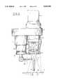
- FIG. 2shows the probe head of the coordinate measuring apparatus of FIG. 1 at an enlarged scale partially in section and partially in side elevation;
- FIG. 3is an embodiment of the probe head changed slightly in comparison to that shown in FIG. 2;
- FIG. 4is a third embodiment of the probe head changed slightly with respect to FIGS. 2 and 3;
- FIG. 5ais a fourth embodiment of the probe head changed slightly with respect to FIGS. 2 and 3;
- FIG. 5bshows the monitor 10 of the coordinate measuring apparatus of FIG. 1 with the image of the probe head picked up by the video camera 6 in FIG. 5a;
- FIG. 6shows a fifth embodiment of the probe head changed slightly with respect to FIGS. 2 and 3;
- FIG. 7shows a sixth embodiment of the probe head changed slightly with respect to FIGS. 2 and 3;
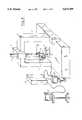
- FIG. 8is a block circuit diagram which shows the essential components of a coordinate measuring apparatus for carrying out an embodiment of the method of the invention.
- the coordinate measuring apparatus shown in FIG. 1is of the portal type and has a measuring table made, for example, of granite on which the workpieces 9 to be measured are placed.
- the granite tablefurthermore serves for guiding the movable portal 2 in the y-direction.
- the transverse beam of the portal 2defines the x-guide for the movable transverse carriage 3 in which the so-called spindle 4 of the coordinate measuring apparatus is journalled so as to be displaceable vertically.
- a mechanical probe head 7 and a video camera 6are attached at the lower end of the spindle 4 via a common holder 5.
- the movement sequences of the coordinate measuring apparatusare monitored by a control 11 which communicates with a computer 12.
- the computercontains the measuring program for the CNC-operation and the evaluation programs for generating the measurement results.
- the image of the workpiece surface picked up by the video camera 6is displayed on a monitor 10.
- FIG. 2the holder 5 mounted at the lower end of the spindle 4, the video probe head 6 attached thereto and the mechanical probe head 7 are shown in more detail.
- the video camerahas an objective 13 which images the workpiece surface on a CCD-chip 14.
- the viewing field of this video probe headcorresponds to the cone identified by 17.
- This viewing fieldis illuminated by a fiber optical annular lamp disposed around the video camera 6.
- an illuminating unitcan be used as described in U.S. Pat. No. 5,038,258.
- the probe ball 8 of the mechanical probeis attached via an electromagnetic probe changing unit 19 known per se on the movable and deflectable part 7a of the probe head.
- the probe ball 8is held via a probe pin 20 in the form of an angled piece which is so dimensioned that the probe ball 8 is located in the sharply imaged region of the viewing field 17 of the video camera. In this way, it is possible to follow the position of the probe ball 8 relative to the workpiece 9 and the bore 9a to be measured there very precisely with the aid of the monitor 10 and to manually control the contact operation when moving into the bore 9a.
- the probe ball 28is attached in a conventional manner via a straight probe pin 30 to the electromechanical probe changing unit 19 of the mechanical probe head 7.
- the probe pin 30is aligned along the probe axis.
- the video camera 26is attached to the holder 5 via a rotational joint 22 and a pivot joint 21 and can therefore be aligned in all spatial directions.
- the video camera 26is so aligned that its objective 23 can image the probe ball 28 on the image sensor 24 for visually viewing the contact operation.
- Reference numeral 27identifies the cone which indicates the dimensions of the viewing field of the video camera.
- the video camera 26furthermore contains an ancillary light source 25 in the form of a laser diode radiating in the visible range and having a collimating optic placed forward thereof.
- the light beam emitted by the laser diodeis reflected into the optical axis of the video camera by a mirror 25a forward of the objective 23 of the video camera. This light beam impinges on the probe ball 28 when the video camera is correctly aligned. The scattered radiation emitted from this location causes the probe ball 28 to appear brightly and clearly on the monitor screen.
- the parallax based on the inclination of the optical axis of the video camera to the workpiece surfaceleads to the situation that the probe ball is more likely to be positioned at the location identified by 128 next to the actual target point when the operator, under visual control with the aid of the monitor, attempts to position the probe ball 28 over specific points of the workpiece 9 which are to be contacted such as shown in FIGS. 3 above the bore 9a.
- the probe headis displaced with the probe pin along the vertical machine axis z and the probe ball is then not lowered into the bore but strikes the surface of the workpiece.
- control of the coordinate measuring apparatuscan be so programmed that the control moves the probe head 7 in two axes simultaneously corresponding to the inclination of the camera axis as indicated by the arrow 129 when moving in the direction toward the workpiece 9.
- the mechanical probe 7 and the video camera 36are vertically aligned as in the embodiment of FIG. 2 and are attached to the holder 5 at the lower end of the spindle 4.
- the probe pin 30 with the probe ball 28 of the mechanical probe 7is aligned vertically along the probe axis.
- the video camera 36is, however, equipped with a pivot mirror 31 which is pivoted into the position shown by the solid outline in FIG. 4 for visually monitoring the position of the probe ball 28 and the pivot mirror deflects the beam path of the objective 33 of the video camera 36 so that the probe ball 28 is located in the viewing field of the sensor 34 of the video camera 36.
- the pivot mirror 31is pivoted as indicated by arrow 32 into the position 31a indicated in phantom outline.
- the holder 5carries the same video camera 6 described with respect to FIG. 2 at the lower end of the spindle 4.
- the mechanical probe head 47is a small direction-independent switching probe head which is seated via an extension 41 on a so-called rotation/pivot joint 42 and therefore can be aligned in any desired spatial direction.
- the probe head 47carries a star probe 40 having five probe balls 48a to 48e.
- the probe head 47is so aligned with the aid of monitor 10 for the visual control of the mechanical contact operation that the star probe 40 lies in the viewing field 17 of the objective 13 of the video camera.
- a probe head 55 of the so-called measuring typeis seated directly on the spindle 4.
- Such a probe headis, for example, described in U.S. Pat. No. 3,869,799 and DE-OS 3,823,993.
- the movable part 55a of this probe headcan be shifted, as indicated by the arrows, in the three spatial directions by actuators (not shown) over paths having a length of several mm or cm.
- An electromagnetic probe changing unitis integrated into the movable part 55a of the measuring probe head 55 as described, for example, in U.S. Pat. No. 4,637,119.
- the change plate of this electromagnetic probe changing unitis identified by 49 and carries at its lower end a small video camera 56 and a mechanical probe head 57 in the form of a so-called quartz oscillator probe.
- the mechanical probe head 57is mounted via an angle piece 51.
- the quartz oscillator probecomprises a quartz crystal oscillating at approximately 40 kHz on which a glass pin 50 having a length of several mm is attached.
- the glass pin 50supports a probe element 58 at its forward end.
- This probe element 58comprises a glass ball fused to the glass pin 50.
- the angle piece 51is rotatably attached to the lower end of the change plate 49 and is aligned in the present case so that the contact element 58 is located in the viewing field of the video camera 56.
- the contact element 58is illuminated by a visible laser beam 52 reflected into the beam path of the video camera and is therefore clearly visible on the screen of the monitor (not shown).
- Filigree structures of a plastic housing 59are measured with manual control with the probe element 58 under visual control with the aid of the monitor of the coordinate measuring apparatus. Good viewing contact is especially important here in order to prevent the glass pin 50 of the quartz oscillator probe from breaking because of shaft contacts.
- a second change plate 79can be used with the optomechanical probe combination shown in FIG. 7.
- This probecomprises a photogrammetric video probe head, that is, a video probe head having two optics (73a and 73b) having an image which is transmitted via fiber optic image conductors (72a and 72b) to the light-sensitive surface of the image sensor 74. In this way, a stereo image of the region 80 is provided. The region 80 is covered in common by the two viewing fields (87a and 87b) of both optics.
- a mechanical quartz oscillator probe 77is mounted between the two optics (73a and 73b) of the video probe head 76.
- the quartz oscillator 81 of the probe 77carries a glass pin having a length of several mm as in the embodiment of FIG. 6.
- a ball 78is fused to the end of the glass pin and defines the contact element. This ball 78 is located in the overlapping region 80 of the two viewing fields (87a and 87b) of the video probe head 76.
- the position of the contact element 78can be excellently followed visually in space and the manual contact operation controlled.
- the locations to be measured on the workpiecesare driven to directly with the probe element 78 under visual control by the operator.
- the electric supply of the video probe head and of the quartz oscillator probeis provided via contacts 82 on the rear side of the exchange plate 49.
- the signals of the image sensor 74reach the control of the coordinate measuring apparatus via these contacts.
- FIG. 8The block diagram of a coordinate measuring apparatus suitable for this method is shown in FIG. 8.
- the coordinate measuring apparatus of FIG. 8corresponds to that shown in FIGS. 1 and 2 with respect to its mechanical configuration with the exception that a probe element 28 is exchanged on the probe head 7 which does not necessarily lie in the image field 17 of the video camera 6.
- the probe elementrather has a spacing (r [x, y, z]) to the focus point 70 of the video camera 6. This spacing can be determined in a manner known per se by calibration in the form of a comparison between the measured values obtained with the mechanical probe head 7 and the measured values determined with the video probe head 6 on a common sample workpiece (master).
- the control 11is connected to the computer 12 of the coordinate measuring apparatus via a data bus.
- the control 11includes the components necessary for the control of the movement sequence of the coordinate measuring apparatus as well as modules which are necessary for detecting measured values.
- reference numeral 90identifies the module which generates the measured value picked up by the mechanical probe head.
- the measured valueis generated from the signals of the photoelectric linear measuring systems in the three measuring axes (x, y, z) of the coordinate measuring apparatus and the signals of the probe head 7 processed in a module 69.
- the control 11includes furthermore a module "image evaluation", which further processes the video signals of the image sensor 14 of the video camera, and, in combination with the signals of the linear measuring systems, supplies the measured value of the optical contact generated by the video camera.
- control 11includes an image generator 61 having an output signal which is supplied via a mixer 64 to the monitor 10.
- the image generatorsuperposes a mark 70' on the monitor image.
- the mark 70'corresponds in form and magnitude to the probe ball 28 while considering the imaging scale.
- This measuring mark 70'represents the focus point 70 of the video camera 6.
- the image of the measuring mark 70'is superposed on the image of the workpiece surface 9. For this reason, the locations on the sample workpiece can be driven to with the probe element simulated in this manner in the context of the learning programming. These locations are thereafter contacted directly in CNC-controlled series measuring operation by the probe ball 28.
- the operatorbrings, hand-controlled under visual control of the monitor image, the measuring mark 70' into alignment with the measuring locations on the geometric elements of the workpiece 9, such as the bore 9a, shown on the monitor and triggers the data transfer.
- the coordinates of the locations to be contactedare stored.
- These coordinatesare thereafter converted into the contact coordinates of the mechanical probe element 28 with the aid of the known spatial relationship (r [x, y, z]) between the mechanical probe element 28 and the focus point (70 or 70') of the video camera.
- the known spatial relationship (r [x, y, z])is determined in the previously described calibration operation.
- the contact coordinatescan then be driven to under computer control automatically with the probe element 28 after a possibly required conversion into the workpiece coordinate system of the CNC-controlled parts to be measured.
- probe pinIt is not necessary to exchange the probe pin with the probe element 28 during the learning programming with the aid of the measuring mark simulating the contact element.
- This probe pincan instead be exchanged subsequently and be calibrated relative to the video camera.
Landscapes
- Physics & Mathematics (AREA)
- General Physics & Mathematics (AREA)
- Length Measuring Devices With Unspecified Measuring Means (AREA)
- A Measuring Device Byusing Mechanical Method (AREA)
- Length Measuring Devices By Optical Means (AREA)
Abstract
Description
For the coordinate measurement on workpieces, coordinate measuring apparatus having measuring or switching probe heads are, as a rule, utilized. Such apparatus directly measure the workpiece surface by touching mechanical contact with the probe element attached to the deflectable part of the probe head. The probe element is, in most cases, a ball.
In addition, coordinate measuring apparatus are known which carry a so-called optical probe head which "touches" the object to be measured without contact. As optical probe heads, in addition to probes operating with light points (such as triangulation probes), mostly so-called video probe heads are utilized, that is, video cameras which detect a greater portion of the workpiece surface. The coordinates of geometric elements of the workpiece of interest are determined then, for example, via a video processing software.
In recent times, combined optically and mechanically contacting coordinate measuring apparatus have become known. One such apparatus is described, for example, in U.S. Pat. No. 4,908,951. The known apparatus has two spindles of which one spindle carries the mechanical probe head while the other spindle holds a video camera having a beam path into which a laser probe is simultaneously reflected for making measurements in the z-coordinate, that is, along the optical axis of the video camera.
Such combined optically and mechanically contacting coordinate measuring apparatus permit not only the measurement of different workpieces such as printed circuit boards or motor housings with the measuring methods best adapted thereto (optically without contact or mechanically contacting). It is also possible to measure locations on the same workpiece first with the video camera and then with the mechanical probe since the mutual reference of the two probe systems can be established via a calibration procedure.
The actual measuring procedure then takes place as described below.
(a) Manually controlled operation: Here, the location on the workpiece to be contacted with the mechanical probe head is approached under direct visual control. After contacting the workpiece with the probe element, which is mostly indicated acoustically, the computer assumes the coordinates of the contact point and the operator drives with the probe element to the next measurement location on the surface of the workpiece. While measuring with the video camera, the video camera is moved over the corresponding location on the workpiece and focusing of the image of the workpiece surface is monitored with the aid of the monitor and thereafter, the transfer of data is triggered.
(b) CNC-operation: Here, the positions to be approached by the mechanical probe head or by the video camera are either in part remotely programmed or, in the context of a so-called learning program, the movement sequence is carried out on a sample piece including driving to the contact locations for the special measuring program, then stored and then repeated as often as desired in the series measurement operation on a series of like parts to be measured.
The manually controlled contacting presents problems especially for complicated workpieces having poorly accessible inner surfaces because it is difficult to maintain visual contact with the probe element. If this visual contact is lost, then the danger is present that the probe head or probe pin is damaged by a collision with the workpiece or the incorrect location on the workpiece is contacted. This danger is present also during the learn programming of the CNC-operation since the probe element is there likewise manually-controlled driven.
From East German Patent 12,609, it is known to measure bores with the aid of an illuminating measuring bead under visual control. The measuring bead is brought mechanically into contact with the bore wall. The method described in this East German patent is, however, not applicable to a coordinate measuring apparatus and the measuring bead is not a mechanical probe such that this probe can independently register the coordinates of the contact point. Instead, the measuring bead simply serves as a measuring mark with the aid of which the bore diameter is determined visually with an ocular plate in a measuring microscope. The method can furthermore only be used for bores which are accessible from both ends.
It is the object of the present invention to increase the safety in the mechanical contact operation with a coordinate measuring apparatus in the manually-controlled operation and to simplify the measuring sequence for the operator.
Here, approaching and contacting the location to be mechanically measured is monitored by the probe element visually with the aid of the video camera and its monitor. This is especially then advantageous when very small probe pins are lowered into bores with respect to which the direct visual contact cannot be maintained or can be maintained only with great difficulties. The method does not require greater additional complexity because video camera and monitor are present for a combined optically and mechanically measuring coordinate measuring apparatus. It is only necessary to ensure that the probe element is located in the viewing field of the video camera during the measurement operation. This can be ensured by a suitable alignment of video camera and mechanical probe in that, for example, the probe element is attached via an extension or an angle piece to the probe head or the probe element or the entire mechanical probe head or the video camera is rotationally or pivotally attached to the movable spindle or to the transverse arm of the coordinate measuring apparatus. It is also possible to direct only the beam path of the video camera in the direction toward the probe element, for example, via a mirror or a prism or suitable flexible image-conducting elements such as glass fiber cables.
Both the probe head and the video camera are preferably attached to a common carrier so that the spatial/geometric relationship between the mechanical probe head and the video camera is guaranteed to be stable over a long time. To adapt to different measuring tasks, the probe element of the mechanical probe head can be attached to the probe head so as to be exchangeable via a probe changing unit as is customary in such cases.
The invention affords special advantages when the mechanical probe head is a miniaturized probe head in the form of a so-called quartz oscillator probe as described in German utility model registration 9,115,942 and wherein the miniaturized probe head in any event contains a probe pin having a length of only a few mm and a probe element in the form of a ball having a diameter of a tenth of a mm. Here, the danger is especially great that not only the probe pin breaks off in the course of the mechanical contact operation but that the entire probe system can be damaged.
Such a mechanical miniature probe is preferably attached together with a video camera to the same exchange holder and can, for example, be exchanged for a large probe pin on the probe head of a coordinate measuring apparatus operating purely mechanically. This coordinate measuring apparatus can then additionally perform measuring tasks with the aid of the quartz oscillator probe which can be solved neither with a conventional mechanical probe head nor with a purely optical, for example, video probe head.
To make the probe head more visible, it can furthermore be advantageous to provide an illuminating device which excites the probe element to transmit scatter radiation.
Finally, and especially for work in bores and other hollow spaces of the workpiece, it is advantageous to configure the video probe head so that it contains two optics suitable for receiving stereo images and to mount the probe element in that portion of the viewing field which is common to both optics. In this way, the depth resolution of this photometric optical video probe head can be utilized for measurements in the z-direction. At the same time, the positioning of the probe head by the operator is improved when utilizing a suitable 3-D monitor. One such monitor is described, for example, in U.S. patent application Ser. No. 07/961,353, filed Oct. 15, 1992, now abandoned which is incorporated herein by reference.
When the optical axis of the video camera is inclined with respect to one of the machine axes of the coordinate measuring apparatus, then it is difficult to manually drive to the desired point on the workpiece because of the parallax between the drive direction and the target direction. Here, it is advantageous to configure the control of the coordinate measuring apparatus so that the probe head of the apparatus is displaced simultaneously in at least two machine axes in correspondence to the angle of inclination between the optical axis of the video camera and the machine axis under consideration.
With the method of the invention, not only is the measuring sequence made more reliable and is simplified for the actual inspection of the parts to be tested, but the programing of the measuring sequences on sample workpieces is simplified in that the locations on the workpiece to be contacted can be driven to in advance, that is, in the course of the learn programming, not with a mechanical probe but with a video probe head. Since no mechanical probe is utilized in the course of this manually controlled procedure, damage is reliably avoided. In this context, it is advantageous when the locations on the workpiece to be contacted mechanically later are driven to with the video probe head under monitor control and an electronically generated mark is superimposed on the image on the monitor. The mark corresponds in form and size to the probe element of the mechanical probe head with which the actual measuring sequence is subsequently carried out.
Furthermore, it is advantageous to assign an illuminating unit having several light sources to the video camera. The several light sources radiate in different directions and their electronics are so configured that the light sources are driven individually or in groups. With such an illuminating unit as it is described inter alia in U.S. Pat. No. 5,038,258, the intensity and the direction of incidence of the light can be adjusted in a targeted manner and can be optimally adapted to the particular measuring task.
The invention will now be described with reference to the drawings wherein:
FIG. 1 is a simplified perspective sketch of a coordinate measuring apparatus suitable for carrying out the method of the invention;
FIG. 2 shows the probe head of the coordinate measuring apparatus of FIG. 1 at an enlarged scale partially in section and partially in side elevation;
FIG. 3 is an embodiment of the probe head changed slightly in comparison to that shown in FIG. 2;
FIG. 4 is a third embodiment of the probe head changed slightly with respect to FIGS. 2 and 3;
FIG. 5a is a fourth embodiment of the probe head changed slightly with respect to FIGS. 2 and 3;
FIG. 5b shows themonitor 10 of the coordinate measuring apparatus of FIG. 1 with the image of the probe head picked up by thevideo camera 6 in FIG. 5a;
FIG. 6 shows a fifth embodiment of the probe head changed slightly with respect to FIGS. 2 and 3;
FIG. 7 shows a sixth embodiment of the probe head changed slightly with respect to FIGS. 2 and 3;
FIG. 8 is a block circuit diagram which shows the essential components of a coordinate measuring apparatus for carrying out an embodiment of the method of the invention.
The coordinate measuring apparatus shown in FIG. 1 is of the portal type and has a measuring table made, for example, of granite on which theworkpieces 9 to be measured are placed. The granite table furthermore serves for guiding themovable portal 2 in the y-direction. The transverse beam of theportal 2 defines the x-guide for the movable transverse carriage 3 in which the so-calledspindle 4 of the coordinate measuring apparatus is journalled so as to be displaceable vertically. Amechanical probe head 7 and avideo camera 6 are attached at the lower end of thespindle 4 via acommon holder 5.
The movement sequences of the coordinate measuring apparatus are monitored by acontrol 11 which communicates with acomputer 12. The computer contains the measuring program for the CNC-operation and the evaluation programs for generating the measurement results.
The image of the workpiece surface picked up by thevideo camera 6 is displayed on amonitor 10.
In FIG. 2, theholder 5 mounted at the lower end of thespindle 4, thevideo probe head 6 attached thereto and themechanical probe head 7 are shown in more detail. The video camera has an objective 13 which images the workpiece surface on a CCD-chip 14. The viewing field of this video probe head corresponds to the cone identified by 17. This viewing field is illuminated by a fiber optical annular lamp disposed around thevideo camera 6. In lieu of the annular lamp, an illuminating unit can be used as described in U.S. Pat. No. 5,038,258.
Theprobe ball 8 of the mechanical probe is attached via an electromagneticprobe changing unit 19 known per se on the movable anddeflectable part 7a of the probe head. Theprobe ball 8 is held via aprobe pin 20 in the form of an angled piece which is so dimensioned that theprobe ball 8 is located in the sharply imaged region of theviewing field 17 of the video camera. In this way, it is possible to follow the position of theprobe ball 8 relative to theworkpiece 9 and thebore 9a to be measured there very precisely with the aid of themonitor 10 and to manually control the contact operation when moving into thebore 9a.
The same is achieved also with the configuration shown in FIG. 3 according to an alternate embodiment of the invention. There, theprobe ball 28 is attached in a conventional manner via astraight probe pin 30 to the electromechanicalprobe changing unit 19 of themechanical probe head 7. Theprobe pin 30 is aligned along the probe axis. In contrast however, thevideo camera 26 is attached to theholder 5 via a rotational joint 22 and a pivot joint 21 and can therefore be aligned in all spatial directions. Thevideo camera 26 is so aligned that its objective 23 can image theprobe ball 28 on theimage sensor 24 for visually viewing the contact operation.Reference numeral 27 identifies the cone which indicates the dimensions of the viewing field of the video camera.
Thevideo camera 26 furthermore contains an ancillarylight source 25 in the form of a laser diode radiating in the visible range and having a collimating optic placed forward thereof. The light beam emitted by the laser diode is reflected into the optical axis of the video camera by a mirror 25a forward of theobjective 23 of the video camera. This light beam impinges on theprobe ball 28 when the video camera is correctly aligned. The scattered radiation emitted from this location causes theprobe ball 28 to appear brightly and clearly on the monitor screen.
The parallax based on the inclination of the optical axis of the video camera to the workpiece surface leads to the situation that the probe ball is more likely to be positioned at the location identified by 128 next to the actual target point when the operator, under visual control with the aid of the monitor, attempts to position theprobe ball 28 over specific points of theworkpiece 9 which are to be contacted such as shown in FIGS. 3 above thebore 9a. In the following contact operation, the probe head is displaced with the probe pin along the vertical machine axis z and the probe ball is then not lowered into the bore but strikes the surface of the workpiece. In order to avoid this and to facilitate operation, the control of the coordinate measuring apparatus can be so programmed that the control moves theprobe head 7 in two axes simultaneously corresponding to the inclination of the camera axis as indicated by thearrow 129 when moving in the direction toward theworkpiece 9.
In the embodiment of FIG. 4, themechanical probe 7 and thevideo camera 36 are vertically aligned as in the embodiment of FIG. 2 and are attached to theholder 5 at the lower end of thespindle 4. Theprobe pin 30 with theprobe ball 28 of themechanical probe 7 is aligned vertically along the probe axis.
Thevideo camera 36 is, however, equipped with apivot mirror 31 which is pivoted into the position shown by the solid outline in FIG. 4 for visually monitoring the position of theprobe ball 28 and the pivot mirror deflects the beam path of the objective 33 of thevideo camera 36 so that theprobe ball 28 is located in the viewing field of thesensor 34 of thevideo camera 36.
For measuring tasks wherein only thevideo camera 36 is required, thepivot mirror 31 is pivoted as indicated byarrow 32 into theposition 31a indicated in phantom outline.
In the embodiment of FIG. 5a, theholder 5 carries thesame video camera 6 described with respect to FIG. 2 at the lower end of thespindle 4. Themechanical probe head 47 is a small direction-independent switching probe head which is seated via anextension 41 on a so-called rotation/pivot joint 42 and therefore can be aligned in any desired spatial direction. Theprobe head 47 carries astar probe 40 having fiveprobe balls 48a to 48e.
Theprobe head 47 is so aligned with the aid ofmonitor 10 for the visual control of the mechanical contact operation that thestar probe 40 lies in theviewing field 17 of theobjective 13 of the video camera.
In the embodiment of FIG. 6, aprobe head 55 of the so-called measuring type is seated directly on thespindle 4. Such a probe head is, for example, described in U.S. Pat. No. 3,869,799 and DE-OS 3,823,993.
Themovable part 55a of this probe head can be shifted, as indicated by the arrows, in the three spatial directions by actuators (not shown) over paths having a length of several mm or cm. An electromagnetic probe changing unit is integrated into themovable part 55a of the measuringprobe head 55 as described, for example, in U.S. Pat. No. 4,637,119. The change plate of this electromagnetic probe changing unit is identified by 49 and carries at its lower end asmall video camera 56 and amechanical probe head 57 in the form of a so-called quartz oscillator probe. Themechanical probe head 57 is mounted via anangle piece 51. The quartz oscillator probe comprises a quartz crystal oscillating at approximately 40 kHz on which aglass pin 50 having a length of several mm is attached. Theglass pin 50 supports aprobe element 58 at its forward end. Thisprobe element 58 comprises a glass ball fused to theglass pin 50.
Theangle piece 51 is rotatably attached to the lower end of thechange plate 49 and is aligned in the present case so that thecontact element 58 is located in the viewing field of thevideo camera 56. Thecontact element 58 is illuminated by avisible laser beam 52 reflected into the beam path of the video camera and is therefore clearly visible on the screen of the monitor (not shown).
Filigree structures of aplastic housing 59 are measured with manual control with theprobe element 58 under visual control with the aid of the monitor of the coordinate measuring apparatus. Good viewing contact is especially important here in order to prevent theglass pin 50 of the quartz oscillator probe from breaking because of shaft contacts.
Work is conducted not only in the switching mode of operation when measuring ridges and recesses of theplastic housing 59 and theprobe element 58 is moved with the aid of the drives in the three axes of the coordinate measuring apparatus. Rather, it is likewise possible to scan smaller regions of the workpiece surface at standstill of the machine axes with the actuators integrated into theprobe head 55. Here, theprobe ball 58 remains in direct contact with theworkpiece 59 during the scan operation.
In lieu of thechange plate 49 in the embodiment of FIG. 6, asecond change plate 79 can be used with the optomechanical probe combination shown in FIG. 7. This probe comprises a photogrammetric video probe head, that is, a video probe head having two optics (73a and 73b) having an image which is transmitted via fiber optic image conductors (72a and 72b) to the light-sensitive surface of theimage sensor 74. In this way, a stereo image of theregion 80 is provided. Theregion 80 is covered in common by the two viewing fields (87a and 87b) of both optics.
A mechanicalquartz oscillator probe 77 is mounted between the two optics (73a and 73b) of thevideo probe head 76. Thequartz oscillator 81 of theprobe 77 carries a glass pin having a length of several mm as in the embodiment of FIG. 6. Aball 78 is fused to the end of the glass pin and defines the contact element. Thisball 78 is located in the overlappingregion 80 of the two viewing fields (87a and 87b) of thevideo probe head 76.
Accordingly, with a suitable stereo monitor, the position of thecontact element 78 can be excellently followed visually in space and the manual contact operation controlled. Here, the locations to be measured on the workpieces are driven to directly with theprobe element 78 under visual control by the operator.
The electric supply of the video probe head and of the quartz oscillator probe is provided viacontacts 82 on the rear side of theexchange plate 49. The signals of theimage sensor 74 reach the control of the coordinate measuring apparatus via these contacts.
In addition to manually driving to the measuring locations with the mechanical probe element, it is also possible to drive to the measurement locations only with the video camera under monitor control in the context of the learning programming and to specify the contact positions which are thereafter to be contacted in the CNC run by the mechanical probe element. The block diagram of a coordinate measuring apparatus suitable for this method is shown in FIG. 8. The coordinate measuring apparatus of FIG. 8 corresponds to that shown in FIGS. 1 and 2 with respect to its mechanical configuration with the exception that aprobe element 28 is exchanged on theprobe head 7 which does not necessarily lie in theimage field 17 of thevideo camera 6. The probe element rather has a spacing (r [x, y, z]) to thefocus point 70 of thevideo camera 6. This spacing can be determined in a manner known per se by calibration in the form of a comparison between the measured values obtained with themechanical probe head 7 and the measured values determined with thevideo probe head 6 on a common sample workpiece (master).
Thecontrol 11 is connected to thecomputer 12 of the coordinate measuring apparatus via a data bus. Thecontrol 11 includes the components necessary for the control of the movement sequence of the coordinate measuring apparatus as well as modules which are necessary for detecting measured values. For example,reference numeral 90 identifies the module which generates the measured value picked up by the mechanical probe head. The measured value is generated from the signals of the photoelectric linear measuring systems in the three measuring axes (x, y, z) of the coordinate measuring apparatus and the signals of theprobe head 7 processed in amodule 69. Thecontrol 11 includes furthermore a module "image evaluation", which further processes the video signals of theimage sensor 14 of the video camera, and, in combination with the signals of the linear measuring systems, supplies the measured value of the optical contact generated by the video camera.
Furthermore, thecontrol 11 includes animage generator 61 having an output signal which is supplied via amixer 64 to themonitor 10. The image generator superposes a mark 70' on the monitor image. The mark 70' corresponds in form and magnitude to theprobe ball 28 while considering the imaging scale. This measuring mark 70' represents thefocus point 70 of thevideo camera 6.
The image of the measuring mark 70' is superposed on the image of theworkpiece surface 9. For this reason, the locations on the sample workpiece can be driven to with the probe element simulated in this manner in the context of the learning programming. These locations are thereafter contacted directly in CNC-controlled series measuring operation by theprobe ball 28. To carry out this method, the operator (during the learning programming) brings, hand-controlled under visual control of the monitor image, the measuring mark 70' into alignment with the measuring locations on the geometric elements of theworkpiece 9, such as thebore 9a, shown on the monitor and triggers the data transfer. The coordinates of the locations to be contacted are stored. These coordinates are thereafter converted into the contact coordinates of themechanical probe element 28 with the aid of the known spatial relationship (r [x, y, z]) between themechanical probe element 28 and the focus point (70 or 70') of the video camera. The known spatial relationship (r [x, y, z]) is determined in the previously described calibration operation. The contact coordinates can then be driven to under computer control automatically with theprobe element 28 after a possibly required conversion into the workpiece coordinate system of the CNC-controlled parts to be measured.
It is not necessary to exchange the probe pin with theprobe element 28 during the learning programming with the aid of the measuring mark simulating the contact element. This probe pin can instead be exchanged subsequently and be calibrated relative to the video camera.
Claims (15)
1. A method of making coordinate measurements on a workpiece with a coordinate measuring apparatus carrying a video camera and a mechanical probe element for contact measuring the workpiece surface, the method comprising the steps of:
mounting said probe element on a probe head of the coordinate measuring apparatus;
changing the position of an articulated joint so as to align the mechanical probe element and the video camera to each other so that the probe element is located in the viewing field of the video camera; and,
driving to the locations on the workpiece to be mechanically contacted with the probe element under visual control with the aid of a monitor connected to the video camera.
2. The method of claim 1, wherein said video camera defines a contact point and wherein a spatial relationship (r(x, y, z)) exists between the mechanical probe element and said contact point which is determined by a calibration procedure; and, wherein the method comprises the further steps of:
first driving to the locations to be contacted on a sample workpiece with the aid of the video camera under visual control and manual control;
picking up the coordinates of said locations to be contacted with the video camera and storing said coordinates;
converting the stored coordinates with the aid of said spatial relationship (r(x, y, z)) into the contact coordinates of the mechanical probe element; and,
driving to the same locations on the workpiece with the mechanical probe element under automatic control.
3. The method of claim 2, the method comprising the further steps of:
displaying the image of the workpiece picked up on said video camera on said monitor; and,
electronically generating a mark having the form and size of the probe element and superposing said mark on said image.
4. The method of claim 3, wherein said mechanical probe head carries several probe elements and the method comprises superposing several marks of different form and size selectively on the image of the workpiece surface on the monitor.
5. A coordinate measuring apparatus for making measurements on a workpiece, the coordinate measuring apparatus comprising:
a monitor for displaying an image of the workpiece;
a video camera having a field of view and being connected to said monitor for supplying said image thereto;
a movable mechanical probe head having a probe changing unit and a probe element being mounted on said probe head via said probe changing unit to obtain measurements of the workpiece and said probe head including means for emitting signals indicative of said measurements;
computer and control means for processing said signals and for controlling the movement of said probe head relative to the workpiece; and,
an articulated joint connected between said video camera and said mechanical probe for aligning said mechanical probe head and said video camera so as to cause said probe element to be in said field of view.
6. The coordinate measuring apparatus of claim 5, said probe head including a joint for connecting said probe element to said probe head so as to permit said probe element to be rotated and/or pivoted relative to said probe head.
7. The coordinate measuring apparatus of claim 5, further comprising said articulated joint being connected directly to said camera for rotating and/or pivoting said video camera relative to the workpiece.
8. The coordinate measuring apparatus of claim 5, further comprising a changing unit; and, said video camera and said mechanical probe head both being attached to said changing unit.
9. The coordinate measuring apparatus of claim 5, said video camera and said mechanical probe head conjointly defining an ancillary probe head of said coordinate measuring apparatus.
10. The coordinate measuring apparatus of claim 5, said mechanical probe head being a miniature probe head in the form of a quartz oscillator probe.
11. The coordinate measuring apparatus of claim 5, further comprising an illuminating unit for directing illuminating radiation onto said probe element thereby causing scattered radiation to emanate therefrom to make said probe element to appear bright and clear on said monitor.
12. The coordinate measuring apparatus of claim 5, said video camera having two optics for receiving stereo images; said two optics having respective viewing fields conjointly defining a common region wherein respective portions of said viewing fields overlap; and, said probe element being disposed in said common region.
13. The coordinate measuring apparatus of claim 5, said coordinate measuring apparatus having a plurality of machine axes and said video camera defining an optical axis inclined with respect to one of said machine axes; and, said computer and control means being adapted to move said mechanical probe head in at least two coordinate directions corresponding to the angle of inclination between said optical axis and said one machine axis.
14. The coordinate measuring apparatus of claim 5, further comprising an illuminating device for said video camera, said illuminating device being mounted on said video camera and having a plurality of light sources for radiating in various directions; and, means for driving said light sources individually or in groups so as to adjust the intensity thereof and/or the direction of the illuminating light.
15. A coordinate measuring apparatus for making measurements on a workpiece, the coordinate measuring apparatus comprising:
a monitor for displaying an image of the workpiece;
a video camera having a field of view and being connected to said monitor for supplying said image thereto;
a movable mechanical probe head having a probe changing unit and a probe element being mounted on said probe head via said probe changing unit to obtain measurements of the workpiece and said probe head including means for emitting signals indicative of said measurements;
computer and control means for processing said signals and for controlling the movement of said probe head relative to the workpiece;
a deflector for deflecting the beam path of said video camera in the direction toward the probe element; and,
a pivot joint connecting said deflector to said video camera for adjusting said beam path of said video camera so as to cause said probe element to be in said field of view.
Applications Claiming Priority (3)
| Application Number | Priority Date | Filing Date | Title |
|---|---|---|---|
| DE4232118.2 | 1992-09-25 | ||
| DE4232118 | 1992-09-25 | ||
| PCT/EP1993/002523WO1994008205A1 (en) | 1992-09-25 | 1993-09-17 | Method of measuring the coordinates of workpieces |
Publications (1)
| Publication Number | Publication Date |
|---|---|
| US5615489Atrue US5615489A (en) | 1997-04-01 |
Family
ID=6468805
Family Applications (1)
| Application Number | Title | Priority Date | Filing Date |
|---|---|---|---|
| US08/244,497Expired - LifetimeUS5615489A (en) | 1992-09-25 | 1993-09-17 | Method of making coordinate measurements on workpieces |
Country Status (5)
| Country | Link |
|---|---|
| US (1) | US5615489A (en) |
| EP (1) | EP0614517B1 (en) |
| JP (1) | JP3612068B2 (en) |
| DE (2) | DE4327250C5 (en) |
| WO (1) | WO1994008205A1 (en) |
Cited By (105)
| Publication number | Priority date | Publication date | Assignee | Title |
|---|---|---|---|---|
| US5778548A (en)* | 1995-05-16 | 1998-07-14 | Dea-Brown & Sharpe S.P.A. | Viewing device and method for three-dimensional noncontacting measurements |
| US5825666A (en)* | 1995-06-07 | 1998-10-20 | Freifeld; Daniel | Optical coordinate measuring machines and optical touch probes |
| US6154972A (en)* | 1998-07-16 | 2000-12-05 | Mitutoyo Corporation | Measuring machine with cleaning device |
| WO2002006765A1 (en)* | 2000-07-13 | 2002-01-24 | Werth Messtechnik Gmbh | Method for carrying out the non-contact measurement of geometries of objects |
| US6441910B1 (en)* | 1998-05-29 | 2002-08-27 | Werth Messtechnik Gmbh | System for measuring structures of an object |
| EP1236972A2 (en) | 2001-03-02 | 2002-09-04 | Mitutoyo Corporation | Method and apparatus for calibrating measuring machines |
| WO2002068904A1 (en)* | 2001-02-23 | 2002-09-06 | Carl Zeiss | Co-ordinate measuring device having a probehead for probing a workplace |
| US20020131633A1 (en)* | 2001-03-13 | 2002-09-19 | Zwick Robert Leonard | System and method for machine vision inspection through platen |
| US6477784B2 (en)* | 1998-06-17 | 2002-11-12 | Mycrona Gmbh | Coordinate measuring machine having a non-sensing probe |
| US20020166220A1 (en)* | 2001-05-11 | 2002-11-14 | United Air Lines, Inc. | Process for repairing a structure |
| US20030048448A1 (en)* | 2001-03-19 | 2003-03-13 | Fleming Timothy J. | Automated apparatus for testing optical filters |
| US20030048455A1 (en)* | 2001-03-19 | 2003-03-13 | Fleming Timothy J. | Goniometer |
| FR2829571A1 (en)* | 2001-09-11 | 2003-03-14 | Ms Mesure | Three dimensional digital metrology measurement of objects using a micro-machine, uses contact and/or laser non contact at end of rod linked to three dimensional positioning system |
| US20030059100A1 (en)* | 2001-03-19 | 2003-03-27 | Fleming Timothy J. | Method and apparatus for calibrating a vision system to a parts handling device |
| US6543150B2 (en)* | 2000-05-01 | 2003-04-08 | Mitutoyo Corporation | Form measuring sensor and form measuring instrument |
| EP1316777A1 (en)* | 2001-11-22 | 2003-06-04 | Wolfgang Madlener | Method and device for the three dimensional measuring of workpieces on a machine tool |
| US20030177653A1 (en)* | 2002-03-19 | 2003-09-25 | Romain Granger | Sensor for a machine for measuring three-dimensional coordinates |
| US20030184765A1 (en)* | 2002-03-13 | 2003-10-02 | Andrea Gurny-Brosch | Apparatus for measuring a measurement object |
| US6646750B1 (en)* | 1998-04-11 | 2003-11-11 | Werth Messtechnik Gmbh | Method and arrangement for measuring the structures of an object |
| US6651351B1 (en)* | 1997-06-12 | 2003-11-25 | Werth Messtechnik Gmbh | Coordinate measuring instrument with feeler element and optic sensor for measuring the position of the feeler |
| US20040148126A1 (en)* | 2003-01-24 | 2004-07-29 | Mitutoyo Corporation | Measuring instrument |
| US20040172215A1 (en)* | 2001-06-12 | 2004-09-02 | Russell Gary W. | Communication method and common control bus interconnecting a controller and a precision measurement assembly |
| US20040174537A1 (en)* | 2001-07-16 | 2004-09-09 | Detlef Ferger | Method for measuring surface properties and co-ordinate measuring device |
| US6822749B1 (en)* | 1998-04-11 | 2004-11-23 | Werth Messtechnik Gmbh | Method and arrangement for determining the geometry of objects using a coordinate measuring device |
| US20050151963A1 (en)* | 2004-01-14 | 2005-07-14 | Sandeep Pulla | Transprojection of geometry data |
| WO2005088246A1 (en)* | 2004-03-10 | 2005-09-22 | Carl Zeiss Industrielle Messtechnik Gmbh | Co-ordinate measuring system and co-ordinate measuring method that uses a co-ordinate measuring device |
| US20050223570A1 (en)* | 2002-09-26 | 2005-10-13 | Honda Giken Kogyo Kabushiki Kaisha | Mechanical scribing apparatus with controlling force of a scribing cutter |
| US20050235506A1 (en)* | 2004-04-22 | 2005-10-27 | Eastman Kodak Company | Method for profilometer position registration |
| US20050259271A1 (en)* | 2000-09-20 | 2005-11-24 | Ralf Christoph | Assembly and method for the optical-tactile measurement of a structure |
| US7020324B2 (en)* | 2000-05-04 | 2006-03-28 | Daniel Freifeld | Precision measurement of tube wall thickness |
| WO2006094641A1 (en)* | 2005-03-11 | 2006-09-14 | Forschungszentrum Karlsruhe Gmbh | Method and device for measuring structures of an object |
| US20060283366A1 (en)* | 2005-06-21 | 2006-12-21 | Fritz Gegauf Aktiengesellschaft Bernina-Nahmaschinenfabrik | Method and device for minimizing stitching faults in embroidering devices |
| US20070086620A1 (en)* | 2005-10-19 | 2007-04-19 | Mitutoyo Corporation | Probe observing device and surface texture measuring device |
| US20070256311A1 (en)* | 2006-05-01 | 2007-11-08 | Paul Ferrari | Sealed battery for coordinate measurement machine |
| US20080024753A1 (en)* | 2006-07-31 | 2008-01-31 | Mitutoyo Corporation | Multi-range non-contact probe |
| US20080024793A1 (en)* | 2006-07-28 | 2008-01-31 | Mitutoyo Corporation | Non-contact probe control interface |
| US20080127501A1 (en)* | 2006-11-20 | 2008-06-05 | Eaton Homer L | Coordinate measurement machine with improved joint |
| US20090010740A1 (en)* | 2008-03-28 | 2009-01-08 | Paul Ferrari | Coordinate measuring machine with rotatable grip |
| US20090013547A1 (en)* | 2007-07-09 | 2009-01-15 | Paul Ferrari | Joint for coordinate measurement device |
| US20090013548A1 (en)* | 2006-12-22 | 2009-01-15 | Paul Ferrari | Joint axis for coordinate measurement machine |
| WO2009038465A1 (en)* | 2007-09-17 | 2009-03-26 | Conoptica As | Rotating part position and change finding method and apparatus |
| US20090083985A1 (en)* | 2007-09-28 | 2009-04-02 | Romer / Cimcore | Coordinate measurement machine |
| US7578069B2 (en) | 2004-01-14 | 2009-08-25 | Hexagon Metrology, Inc. | Automated robotic measuring system |
| USD599226S1 (en) | 2008-04-11 | 2009-09-01 | Hexagon Metrology, Inc. | Portable coordinate measurement machine |
| US20090243532A1 (en)* | 2005-09-13 | 2009-10-01 | Romer Inc. | Vehicle having an articulator |
| US20090241360A1 (en)* | 2008-03-28 | 2009-10-01 | Hogar Tait | Systems and methods for improved coordination acquisition member comprising calibration information |
| US20090266445A1 (en)* | 2008-04-28 | 2009-10-29 | Lee-Cheng Chang | Work Bench for a Hand Jointer |
| US20090271996A1 (en)* | 2008-05-05 | 2009-11-05 | Paul Ferrari | Systems and methods for calibrating a portable coordinate measurement machine |
| WO2009141606A1 (en) | 2008-05-19 | 2009-11-26 | Renishaw Plc | Optical inspection probe |
| US20100095542A1 (en)* | 2008-10-16 | 2010-04-22 | Romer, Inc. | Articulating measuring arm with laser scanner |
| US20100169041A1 (en)* | 2008-12-27 | 2010-07-01 | Hong Fu Jin Precision Industry (Shenzhen) Co., Ltd | System and method for displaying illustrative information of measured data |
| US20100225928A1 (en)* | 2006-01-19 | 2010-09-09 | Forschungszentrum Karlsruhe Gmbh | Device for measuring structures of an object |
| US7805854B2 (en) | 2006-05-15 | 2010-10-05 | Hexagon Metrology, Inc. | Systems and methods for positioning and measuring objects using a CMM |
| US20100294399A1 (en)* | 2009-05-22 | 2010-11-25 | Bor-Yann Chuang | Working platform provided with a manual wood planer |
| US20100325907A1 (en)* | 2009-06-30 | 2010-12-30 | Hexagon Metrology Ab | Coordinate measurement machine with vibration detection |
| US20110107612A1 (en)* | 2009-11-06 | 2011-05-12 | Hexagon Metrology Ab | Articulated arm |
| EP2322897A1 (en)* | 2009-11-11 | 2011-05-18 | Günther Battenberg | Method and device for measuring workpieces comprising a optical and mechanical coordinate measuring machine |
| USD643319S1 (en) | 2010-03-29 | 2011-08-16 | Hexagon Metrology Ab | Portable coordinate measurement machine |
| US20110213247A1 (en)* | 2010-01-08 | 2011-09-01 | Hexagon Metrology, Inc. | Articulated arm with imaging device |
| US8127458B1 (en) | 2010-08-31 | 2012-03-06 | Hexagon Metrology, Inc. | Mounting apparatus for articulated arm laser scanner |
| EP2511648A1 (en)* | 2011-04-12 | 2012-10-17 | Komax Holding AG | Measuring assembly and method for determining at least the crimp height of one conductor crimp |
| WO2014039275A1 (en)* | 2012-09-04 | 2014-03-13 | United Technologies Corporation | Visual alignment system and method for workpiece marking |
| US8711365B2 (en) | 2004-12-16 | 2014-04-29 | Werth Messtechnik Gmbh | Coordinate measuring device and method for measuring with a coordinate measuring device |
| US8763267B2 (en) | 2012-01-20 | 2014-07-01 | Hexagon Technology Center Gmbh | Locking counterbalance for a CMM |
| US20150073584A1 (en)* | 2013-09-10 | 2015-03-12 | Andrew Goodale | Wireless vision systems and methods for use in harsh environments |
| WO2015039404A1 (en)* | 2013-09-22 | 2015-03-26 | 雷孔成 | Pocket three-coordinate length measuring instrument |
| US9019511B2 (en) | 2012-02-27 | 2015-04-28 | Quality Vision International, Inc. | Optical probe for vision measurements |
| US20150159993A1 (en)* | 2013-12-06 | 2015-06-11 | Tesa Sa | Accessory for coordinate measuring machine |
| US9069355B2 (en) | 2012-06-08 | 2015-06-30 | Hexagon Technology Center Gmbh | System and method for a wireless feature pack |
| US9074883B2 (en) | 2009-03-25 | 2015-07-07 | Faro Technologies, Inc. | Device for optically scanning and measuring an environment |
| US20150222594A1 (en)* | 2012-09-05 | 2015-08-06 | Hexagon Technology Center Gmbh | Measuring machine communication with automatic address allocation |
| US9163922B2 (en) | 2010-01-20 | 2015-10-20 | Faro Technologies, Inc. | Coordinate measurement machine with distance meter and camera to determine dimensions within camera images |
| US9163921B2 (en) | 2013-12-18 | 2015-10-20 | Hexagon Metrology, Inc. | Ultra-portable articulated arm coordinate measurement machine |
| US9168654B2 (en) | 2010-11-16 | 2015-10-27 | Faro Technologies, Inc. | Coordinate measuring machines with dual layer arm |
| US9210288B2 (en) | 2009-11-20 | 2015-12-08 | Faro Technologies, Inc. | Three-dimensional scanner with dichroic beam splitters to capture a variety of signals |
| US9250214B2 (en) | 2013-03-12 | 2016-02-02 | Hexagon Metrology, Inc. | CMM with flaw detection system |
| US9329271B2 (en) | 2010-05-10 | 2016-05-03 | Faro Technologies, Inc. | Method for optically scanning and measuring an environment |
| US9372265B2 (en) | 2012-10-05 | 2016-06-21 | Faro Technologies, Inc. | Intermediate two-dimensional scanning with a three-dimensional scanner to speed registration |
| US20160178350A1 (en)* | 2014-12-19 | 2016-06-23 | Quality Vision International, Inc. | Deployment mechanism for optical measurement system |
| US9417316B2 (en) | 2009-11-20 | 2016-08-16 | Faro Technologies, Inc. | Device for optically scanning and measuring an environment |
| US9417056B2 (en) | 2012-01-25 | 2016-08-16 | Faro Technologies, Inc. | Device for optically scanning and measuring an environment |
| US9513107B2 (en) | 2012-10-05 | 2016-12-06 | Faro Technologies, Inc. | Registration calculation between three-dimensional (3D) scans based on two-dimensional (2D) scan data from a 3D scanner |
| US20160363431A1 (en)* | 2015-06-10 | 2016-12-15 | Mitutoyo Corporation | Collision prevention device of measurer |
| US9551575B2 (en) | 2009-03-25 | 2017-01-24 | Faro Technologies, Inc. | Laser scanner having a multi-color light source and real-time color receiver |
| US9594250B2 (en) | 2013-12-18 | 2017-03-14 | Hexagon Metrology, Inc. | Ultra-portable coordinate measurement machine |
| EP3144632A1 (en)* | 2015-09-18 | 2017-03-22 | Hexagon Technology Center GmbH | Coordinate measuring machine having a camera |
| US9607239B2 (en) | 2010-01-20 | 2017-03-28 | Faro Technologies, Inc. | Articulated arm coordinate measurement machine having a 2D camera and method of obtaining 3D representations |
| US9628775B2 (en) | 2010-01-20 | 2017-04-18 | Faro Technologies, Inc. | Articulated arm coordinate measurement machine having a 2D camera and method of obtaining 3D representations |
| US20170138718A1 (en)* | 2014-07-31 | 2017-05-18 | Carl Zeiss Industrielle Messtechnik Gmbh | Probe head for a coordinate measuring machine |
| US20170248399A1 (en)* | 2016-02-25 | 2017-08-31 | Mitutoyo Corporation | Inner-wall measuring instrument and offset-amount calculation method |
| US9759540B2 (en) | 2014-06-11 | 2017-09-12 | Hexagon Metrology, Inc. | Articulating CMM probe |
| CN107199482A (en)* | 2017-06-07 | 2017-09-26 | 广东长盈精密技术有限公司 | Electronic installation, the processing method of housing side opening and its processing unit (plant) |
| US10067231B2 (en) | 2012-10-05 | 2018-09-04 | Faro Technologies, Inc. | Registration calculation of three-dimensional scanner data performed between scans based on measurements by two-dimensional scanner |
| US10281259B2 (en) | 2010-01-20 | 2019-05-07 | Faro Technologies, Inc. | Articulated arm coordinate measurement machine that uses a 2D camera to determine 3D coordinates of smoothly continuous edge features |
| US20190304131A1 (en)* | 2018-04-02 | 2019-10-03 | Quality Vision International Inc. | Alignment system for imaging sensors in multiple orientations |
| CH715610A1 (en)* | 2018-12-04 | 2020-06-15 | Watch Out S A | System and methods for measuring the profile of a part. |
| US11045918B2 (en) | 2016-01-11 | 2021-06-29 | Datron Ag | Method for determining an X-Y-Z reference coordinate of a workpiece, and machine tool |
| US11168971B2 (en)* | 2019-04-19 | 2021-11-09 | The Boeing Company | Systems and methods for evaluating a surface of a bore formed in a structure |
| CN114184114A (en)* | 2021-12-20 | 2022-03-15 | 河源市皓吉达通讯器材有限公司 | Contact type measuring device and method for miniature light plastic product |
| CN114858056A (en)* | 2022-05-19 | 2022-08-05 | 华中科技大学 | Method for automatically measuring hole depths of small deep holes in large quantity based on deep hole measuring device |
| US11435175B2 (en)* | 2019-04-16 | 2022-09-06 | Tokyo Seimitsu Co., Ltd. | Displacement detector, surface shape measuring apparatus, and roundness measuring apparatus |
| DE102021115046A1 (en) | 2021-06-10 | 2022-12-15 | Hans-Georg Grün | Measuring head for a tactile coordinate measuring machine, method for measuring a workpiece with a tactile coordinate measuring machine and coordinate measuring machine |
| US11650050B2 (en) | 2017-02-14 | 2023-05-16 | Renishaw Plc | Method of calibrating a surface sensing device, corresponding calibrating program for a control computer and corresponding calibration kit |
| US11679460B2 (en)* | 2016-11-29 | 2023-06-20 | Hexagon Metrology Kabushiki Kaisha | Three-dimensional measurement device |
| EP4610590A1 (en)* | 2024-02-28 | 2025-09-03 | Quality Vision International Inc. | Interposer tool for shaft measurement |
Families Citing this family (68)
| Publication number | Priority date | Publication date | Assignee | Title |
|---|---|---|---|---|
| JPH06186025A (en)* | 1992-12-16 | 1994-07-08 | Yunisun:Kk | Three dimensional measuring device |
| DE4425879A1 (en)* | 1994-07-09 | 1996-01-11 | Ges Zur Foerderung Angewandter Optik Optoelektronik Quantenelektronik & Spektroskopie Ev | Scoring system for separating components is essentially single crystal substrates |
| DE19639780A1 (en)* | 1996-09-27 | 1998-04-02 | Leitz Brown & Sharpe Mestechni | Combined optical and mechanical measuring instrument for workpieces |
| DE19805892A1 (en)* | 1997-06-12 | 1998-12-24 | Werth Messtechnik Gmbh | Method and arrangement for measuring structures of an object |
| DE19820307C2 (en)* | 1998-05-07 | 2003-01-02 | Mycrona Ges Fuer Innovative Me | Non-contact temperature detection on a multi-coordinate measuring and testing device |
| DE29808320U1 (en)* | 1998-05-12 | 1998-10-15 | Wegu-Messtechnik GmbH, 66787 Wadgassen | Multi-coordinate measuring and testing device |
| DE19847711B4 (en)* | 1998-05-29 | 2004-08-19 | Werth Messtechnik Gmbh | Arrangement for measuring structures of an object |
| EP0965816A3 (en) | 1998-06-17 | 2002-06-19 | MYCRONA Gesellschaft für innovative Messtechnik mbH | Device to measure the geometrical contour of an object |
| US5978748A (en)* | 1998-07-07 | 1999-11-02 | Faro Technologies, Inc. | Host independent articulated arm |
| JP4387454B2 (en)* | 1998-08-25 | 2009-12-16 | 株式会社ミツトヨ | Remote control measurement system |
| JP4386979B2 (en)* | 1998-08-25 | 2009-12-16 | 株式会社ミツトヨ | Remote control measurement system |
| DE29918341U1 (en)* | 1999-10-18 | 2001-03-01 | Tassakos Charalambos | Device for determining the position of measuring points of a measuring object relative to a reference system |
| JP4689890B2 (en)* | 2001-02-08 | 2011-05-25 | 株式会社ミツトヨ | Surface texture measuring device |
| US6998602B2 (en)* | 2001-09-24 | 2006-02-14 | Jpk Instruments Ag | Method of and an apparatus for measuring a specimen by means of a scanning probe microscope |
| DE10226801B4 (en)* | 2002-06-15 | 2005-03-31 | Bundesrepublik Deutschland, vertr. d. d. Bundesministerium für Wirtschaft und Arbeit, dieses vertr. d. d. Präsidenten der Physikalisch-Technischen Bundesanstalt | Surface measuring device and method for mechanical and non-contact optical examination of object surfaces |
| JP4047096B2 (en)* | 2002-08-09 | 2008-02-13 | キヤノン株式会社 | Surface shape measuring apparatus and method |
| DE10240292A1 (en)* | 2002-08-31 | 2004-03-18 | Carl Mahr Holding Gmbh | Combination feeler for metrology and surface coordinate measurement of workpieces, wherein a feeler carrier is positioned by a drive motor and supports a number of different mechanical or non-contact feeler elements |
| JP2004177192A (en)* | 2002-11-26 | 2004-06-24 | Dainippon Printing Co Ltd | Defect height inspection device and defect height inspection method |
| WO2004055475A2 (en)* | 2002-12-13 | 2004-07-01 | Werth Messtechnik Gmbh | Method for measuring a contour of a workpiece by scanning |
| JP2004294311A (en)* | 2003-03-27 | 2004-10-21 | Nikon Corp | Image measuring device |
| FR2868349B1 (en)* | 2004-04-06 | 2006-06-23 | Kreon Technologies Sarl | MIXED, OPTICAL, AND MECHANICAL PROBE, AND METHOD OF RELOCATION THEREFOR |
| DE102005021645B4 (en)* | 2004-09-09 | 2016-09-01 | Werth Messtechnik Gmbh | Method for the opto-tactile measurement of an object |
| EP1846729A1 (en)* | 2004-12-16 | 2007-10-24 | Werth Messtechnik GmbH | Coordinate measuring device and method for measuring with a coordinate measuring device |
| JP4588525B2 (en)* | 2005-05-02 | 2010-12-01 | 株式会社ミツトヨ | Imaging probe |
| JP4500729B2 (en)* | 2005-05-11 | 2010-07-14 | キヤノン株式会社 | Surface shape measuring device |
| JP2007064670A (en)* | 2005-08-29 | 2007-03-15 | Tokyo Seimitsu Co Ltd | Device for measuring surface shape |
| DE102006001531A1 (en) | 2005-09-20 | 2007-03-22 | Werth Messtechnik Gmbh | Method and arrangement for measuring structures of an object |
| DE102006031580A1 (en) | 2006-07-03 | 2008-01-17 | Faro Technologies, Inc., Lake Mary | Method and device for the three-dimensional detection of a spatial area |
| JP5168985B2 (en)* | 2007-03-30 | 2013-03-27 | 株式会社東京精密 | Measuring head adjustment device |
| DE102007000306B4 (en)* | 2007-05-08 | 2015-07-09 | Werth Messtechnik Gmbh | Coordinate measuring machine |
| DE102009031323B4 (en) | 2009-06-30 | 2023-03-30 | M & H Inprocess Messtechnik Gmbh | Signal transmission unit and signal transmission system |
| JP2011085405A (en)* | 2009-10-13 | 2011-04-28 | Mitsutoyo Corp | Surface property measuring instrument |
| US8650939B2 (en) | 2009-10-13 | 2014-02-18 | Mitutoyo Corporation | Surface texture measuring machine and a surface texture measuring method |
| JP5350171B2 (en) | 2009-10-13 | 2013-11-27 | 株式会社ミツトヨ | Offset amount calibration method and surface texture measuring machine |
| JP5350170B2 (en)* | 2009-10-13 | 2013-11-27 | 株式会社ミツトヨ | Surface texture measuring machine |
| JP5350169B2 (en) | 2009-10-13 | 2013-11-27 | 株式会社ミツトヨ | Offset amount calibration method and surface texture measuring machine |
| US9113023B2 (en) | 2009-11-20 | 2015-08-18 | Faro Technologies, Inc. | Three-dimensional scanner with spectroscopic energy detector |
| US9529083B2 (en) | 2009-11-20 | 2016-12-27 | Faro Technologies, Inc. | Three-dimensional scanner with enhanced spectroscopic energy detector |
| EP2504658B1 (en) | 2009-11-26 | 2019-02-27 | Werth Messtechnik GmbH | Method and arrangement for tactile-optical determination of the geometry of a measurement object |
| US8630314B2 (en) | 2010-01-11 | 2014-01-14 | Faro Technologies, Inc. | Method and apparatus for synchronizing measurements taken by multiple metrology devices |
| US8284407B2 (en) | 2010-01-20 | 2012-10-09 | Faro Technologies, Inc. | Coordinate measuring machine having an illuminated probe end and method of operation |
| US8942940B2 (en) | 2010-01-20 | 2015-01-27 | Faro Technologies, Inc. | Portable articulated arm coordinate measuring machine and integrated electronic data processing system |
| WO2011090895A1 (en) | 2010-01-20 | 2011-07-28 | Faro Technologies, Inc. | Portable articulated arm coordinate measuring machine with multi-bus arm technology |
| US8615893B2 (en) | 2010-01-20 | 2013-12-31 | Faro Technologies, Inc. | Portable articulated arm coordinate measuring machine having integrated software controls |
| US8875409B2 (en) | 2010-01-20 | 2014-11-04 | Faro Technologies, Inc. | Coordinate measurement machines with removable accessories |
| US8677643B2 (en) | 2010-01-20 | 2014-03-25 | Faro Technologies, Inc. | Coordinate measurement machines with removable accessories |
| US8832954B2 (en) | 2010-01-20 | 2014-09-16 | Faro Technologies, Inc. | Coordinate measurement machines with removable accessories |
| US8898919B2 (en) | 2010-01-20 | 2014-12-02 | Faro Technologies, Inc. | Coordinate measurement machine with distance meter used to establish frame of reference |
| JP5410330B2 (en)* | 2010-02-24 | 2014-02-05 | 株式会社ミツトヨ | Stylus observation device |
| DE102010014812A1 (en)* | 2010-04-13 | 2011-10-13 | Eads Deutschland Gmbh | Method for measuring vibration characteristics of electronic parts in to-be-examined region of circuit board, involves filtering deflections of electronic parts over time and over surface |
| DE102010018819B4 (en)* | 2010-04-29 | 2012-01-19 | Hommel-Etamic Gmbh | surface metrological |
| GB2501390B (en) | 2010-09-08 | 2014-08-06 | Faro Tech Inc | A laser scanner or laser tracker having a projector |
| DE102010062626A1 (en)* | 2010-12-08 | 2012-06-14 | Robert Bosch Gmbh | Touch probe for detecting the shape, the diameter and / or the roughness of a surface |
| JP5693978B2 (en)* | 2011-01-11 | 2015-04-01 | 株式会社ミツトヨ | Image probe calibration method |
| JP5500653B2 (en)* | 2011-01-21 | 2014-05-21 | 学校法人 中村産業学園 | Position measuring device |
| NL2006590C2 (en)* | 2011-04-12 | 2012-10-15 | W L F M Donkers Beheer B V | DEVICE AND METHOD FOR DETERMINING THE THICKNESS OF THE RHIZOOM OF A PLANT. |
| JP5829884B2 (en)* | 2011-10-18 | 2015-12-09 | 株式会社小坂研究所 | Stylus measuring device |
| DE102011056805A1 (en) | 2011-12-21 | 2013-06-27 | Werth Messtechnik Gmbh | Method for photo-tactile measurement of measurement object or structure, involves operating sensing element with object in contact by flexible sensing extension, where sensing element is vertically vibrated with sensing extension |
| US8997362B2 (en) | 2012-07-17 | 2015-04-07 | Faro Technologies, Inc. | Portable articulated arm coordinate measuring machine with optical communications bus |
| DE102013208397B4 (en)* | 2013-05-07 | 2018-05-24 | Carl Zeiss Industrielle Messtechnik Gmbh | Coordinate measuring machine with an additional, non-contact measuring surface measuring device |
| US11159784B2 (en) | 2014-10-23 | 2021-10-26 | Cognex Corporation | System and method for calibrating a vision system with respect to a touch probe |
| DE102015208772B4 (en) | 2015-05-12 | 2023-09-28 | Carl Zeiss Industrielle Messtechnik Gmbh | Coordinate measuring machine with lighting through which at least one of the touch elements of a button can be illuminated |
| EP3147627B1 (en) | 2015-09-22 | 2023-04-26 | GF Machining Solutions AG | Optical measuring probe calibration |
| DE102015122844A1 (en) | 2015-12-27 | 2017-06-29 | Faro Technologies, Inc. | 3D measuring device with battery pack |
| DE102016220127B4 (en) | 2016-10-14 | 2020-09-03 | Carl Zeiss Industrielle Messtechnik Gmbh | Method for operating a coordinate measuring machine |
| DE102017220833A1 (en)* | 2017-11-22 | 2019-05-23 | Siemens Aktiengesellschaft | Measuring system for detecting the spatial position of a safety pin and method for drilling out a safety pin |
| JP7249846B2 (en)* | 2019-03-28 | 2023-03-31 | ヘキサゴン・メトロジー株式会社 | CALIBRATION METHOD OF CNC MACHINE EQUIPMENT |
| JP7735027B2 (en)* | 2021-02-24 | 2025-09-08 | 株式会社ミツトヨ | Image Probe |
Citations (10)
| Publication number | Priority date | Publication date | Assignee | Title |
|---|---|---|---|---|
| US3869799A (en)* | 1972-08-29 | 1975-03-11 | Zeiss Stiftung | Universal multi-coordinate sensor |
| DE3502388A1 (en)* | 1984-03-01 | 1985-09-05 | Jenoptik Jena Gmbh, Ddr 6900 Jena | Method and device for the optical monitoring of mechanical contacting of a test specimen |
| US4637119A (en)* | 1983-06-03 | 1987-01-20 | Carl-Zeiss-Stiftung, Heidenheim/Brenz | Chucking device for interchangeable holding of probe pins in a coordinate-measuring instrument |
| DE3823993A1 (en)* | 1988-07-15 | 1990-01-18 | Zeiss Carl Fa | Method for coordinate measurement on workpieces |
| US4908951A (en)* | 1988-03-02 | 1990-03-20 | Wegu-Messtechnik Gmbh | Coordinate measuring and testing machine |
| EP0420416A2 (en)* | 1989-09-09 | 1991-04-03 | Renishaw plc | Method and apparatus of datuming a coordinate positioning machine |
| JPH03142301A (en)* | 1989-10-30 | 1991-06-18 | Erionikusu:Kk | Scanning tunnel microscope |
| US5038258A (en)* | 1989-03-02 | 1991-08-06 | Carl-Zeiss-Stiftung | Illuminating arrangement for illuminating an object with incident light |
| DE9115942U1 (en)* | 1991-12-21 | 1992-05-27 | Hahn-Schickard-Gesellschaft für angewandte Forschung e.V., 7000 Stuttgart | Probing device for length measurement technology |
| JPH04225173A (en)* | 1990-12-27 | 1992-08-14 | Hioki Ee Corp | Circuit board inspection equipment |
Family Cites Families (2)
| Publication number | Priority date | Publication date | Assignee | Title |
|---|---|---|---|---|
| DE3809656A1 (en)* | 1988-03-22 | 1989-10-12 | Reinert Guido Georg | Television eyepiece for visual optical devices |
| IT1245014B (en)* | 1991-01-29 | 1994-09-13 | Dea Spa | SYSTEM FOR THE THREE-DIMENSIONAL MEASUREMENT OF SCULPTED SURFACES TO MATHEMATIZE |
- 1993
- 1993-08-13DEDE4327250Apatent/DE4327250C5/ennot_activeExpired - Fee Related
- 1993-09-17USUS08/244,497patent/US5615489A/ennot_activeExpired - Lifetime
- 1993-09-17DEDE59305773Tpatent/DE59305773D1/ennot_activeExpired - Fee Related
- 1993-09-17WOPCT/EP1993/002523patent/WO1994008205A1/enactiveIP Right Grant
- 1993-09-17EPEP93920757Apatent/EP0614517B1/ennot_activeExpired - Lifetime
- 1993-09-17JPJP50863894Apatent/JP3612068B2/ennot_activeExpired - Fee Related
Patent Citations (10)
| Publication number | Priority date | Publication date | Assignee | Title |
|---|---|---|---|---|
| US3869799A (en)* | 1972-08-29 | 1975-03-11 | Zeiss Stiftung | Universal multi-coordinate sensor |
| US4637119A (en)* | 1983-06-03 | 1987-01-20 | Carl-Zeiss-Stiftung, Heidenheim/Brenz | Chucking device for interchangeable holding of probe pins in a coordinate-measuring instrument |
| DE3502388A1 (en)* | 1984-03-01 | 1985-09-05 | Jenoptik Jena Gmbh, Ddr 6900 Jena | Method and device for the optical monitoring of mechanical contacting of a test specimen |
| US4908951A (en)* | 1988-03-02 | 1990-03-20 | Wegu-Messtechnik Gmbh | Coordinate measuring and testing machine |
| DE3823993A1 (en)* | 1988-07-15 | 1990-01-18 | Zeiss Carl Fa | Method for coordinate measurement on workpieces |
| US5038258A (en)* | 1989-03-02 | 1991-08-06 | Carl-Zeiss-Stiftung | Illuminating arrangement for illuminating an object with incident light |
| EP0420416A2 (en)* | 1989-09-09 | 1991-04-03 | Renishaw plc | Method and apparatus of datuming a coordinate positioning machine |
| JPH03142301A (en)* | 1989-10-30 | 1991-06-18 | Erionikusu:Kk | Scanning tunnel microscope |
| JPH04225173A (en)* | 1990-12-27 | 1992-08-14 | Hioki Ee Corp | Circuit board inspection equipment |
| DE9115942U1 (en)* | 1991-12-21 | 1992-05-27 | Hahn-Schickard-Gesellschaft für angewandte Forschung e.V., 7000 Stuttgart | Probing device for length measurement technology |
Cited By (214)
| Publication number | Priority date | Publication date | Assignee | Title |
|---|---|---|---|---|
| US5778548A (en)* | 1995-05-16 | 1998-07-14 | Dea-Brown & Sharpe S.P.A. | Viewing device and method for three-dimensional noncontacting measurements |
| US5825666A (en)* | 1995-06-07 | 1998-10-20 | Freifeld; Daniel | Optical coordinate measuring machines and optical touch probes |
| EP0995967A1 (en)* | 1995-06-07 | 2000-04-26 | Avcom Precision Instruments Company | Optical coordinate measuring machines and optical touch probes |
| US6651351B1 (en)* | 1997-06-12 | 2003-11-25 | Werth Messtechnik Gmbh | Coordinate measuring instrument with feeler element and optic sensor for measuring the position of the feeler |
| US20050000102A1 (en)* | 1997-06-12 | 2005-01-06 | Ralf Christoph | Coordinate measuring instrument with feeler element and optical system for measuring the position of the feeler element |
| US6646750B1 (en)* | 1998-04-11 | 2003-11-11 | Werth Messtechnik Gmbh | Method and arrangement for measuring the structures of an object |
| US6822749B1 (en)* | 1998-04-11 | 2004-11-23 | Werth Messtechnik Gmbh | Method and arrangement for determining the geometry of objects using a coordinate measuring device |
| US6441910B1 (en)* | 1998-05-29 | 2002-08-27 | Werth Messtechnik Gmbh | System for measuring structures of an object |
| US6477784B2 (en)* | 1998-06-17 | 2002-11-12 | Mycrona Gmbh | Coordinate measuring machine having a non-sensing probe |
| US6154972A (en)* | 1998-07-16 | 2000-12-05 | Mitutoyo Corporation | Measuring machine with cleaning device |
| US6543150B2 (en)* | 2000-05-01 | 2003-04-08 | Mitutoyo Corporation | Form measuring sensor and form measuring instrument |
| US7020324B2 (en)* | 2000-05-04 | 2006-03-28 | Daniel Freifeld | Precision measurement of tube wall thickness |
| WO2002006765A1 (en)* | 2000-07-13 | 2002-01-24 | Werth Messtechnik Gmbh | Method for carrying out the non-contact measurement of geometries of objects |
| US20050259271A1 (en)* | 2000-09-20 | 2005-11-24 | Ralf Christoph | Assembly and method for the optical-tactile measurement of a structure |
| WO2002068904A1 (en)* | 2001-02-23 | 2002-09-06 | Carl Zeiss | Co-ordinate measuring device having a probehead for probing a workplace |
| US6789327B2 (en) | 2001-02-23 | 2004-09-14 | Carl Zeiss Industrielle Messtechnik Gmbh | Touch probe with deflection measurement and inspection optics |
| US20040118000A1 (en)* | 2001-02-23 | 2004-06-24 | Roland Roth | Coordinate measuring apparatus for contacting a workpiece, touch probe for a coordinate measuring apparatus and method of operating a coordinate measuring apparatus |
| EP1236972B1 (en)* | 2001-03-02 | 2017-05-10 | Mitutoyo Corporation | Method and apparatus for calibrating measuring machines |
| EP1236972A2 (en) | 2001-03-02 | 2002-09-04 | Mitutoyo Corporation | Method and apparatus for calibrating measuring machines |
| US20020131633A1 (en)* | 2001-03-13 | 2002-09-19 | Zwick Robert Leonard | System and method for machine vision inspection through platen |
| US20030059100A1 (en)* | 2001-03-19 | 2003-03-27 | Fleming Timothy J. | Method and apparatus for calibrating a vision system to a parts handling device |
| US6983547B2 (en) | 2001-03-19 | 2006-01-10 | Veeco Instruments Inc. | Goniometer |
| US20030048448A1 (en)* | 2001-03-19 | 2003-03-13 | Fleming Timothy J. | Automated apparatus for testing optical filters |
| US20030048455A1 (en)* | 2001-03-19 | 2003-03-13 | Fleming Timothy J. | Goniometer |
| US7065892B2 (en)* | 2001-03-19 | 2006-06-27 | Veeco Instruments Inc. | Method and apparatus for calibrating a vision system to a parts handling device |
| US20020166220A1 (en)* | 2001-05-11 | 2002-11-14 | United Air Lines, Inc. | Process for repairing a structure |
| US6948255B2 (en)* | 2001-06-12 | 2005-09-27 | Hexagon Metrology, Ab | Communication method and common control bus interconnecting a controller and a precision measurement assembly |
| US20040172215A1 (en)* | 2001-06-12 | 2004-09-02 | Russell Gary W. | Communication method and common control bus interconnecting a controller and a precision measurement assembly |
| US20040174537A1 (en)* | 2001-07-16 | 2004-09-09 | Detlef Ferger | Method for measuring surface properties and co-ordinate measuring device |
| US7227647B2 (en) | 2001-07-16 | 2007-06-05 | Werth Messtechnik Gmbh | Method for measuring surface properties and co-ordinate measuring device |
| FR2829571A1 (en)* | 2001-09-11 | 2003-03-14 | Ms Mesure | Three dimensional digital metrology measurement of objects using a micro-machine, uses contact and/or laser non contact at end of rod linked to three dimensional positioning system |
| EP1316777A1 (en)* | 2001-11-22 | 2003-06-04 | Wolfgang Madlener | Method and device for the three dimensional measuring of workpieces on a machine tool |
| US20030184765A1 (en)* | 2002-03-13 | 2003-10-02 | Andrea Gurny-Brosch | Apparatus for measuring a measurement object |
| US6927863B2 (en)* | 2002-03-13 | 2005-08-09 | Andrea Gurny-Brosch | Apparatus for measuring a measurement object |
| US20030177653A1 (en)* | 2002-03-19 | 2003-09-25 | Romain Granger | Sensor for a machine for measuring three-dimensional coordinates |
| US7281334B2 (en)* | 2002-09-26 | 2007-10-16 | Satoshi Yonezawa | Mechanical scribing apparatus with controlling force of a scribing cutter |
| US20050223570A1 (en)* | 2002-09-26 | 2005-10-13 | Honda Giken Kogyo Kabushiki Kaisha | Mechanical scribing apparatus with controlling force of a scribing cutter |
| US7155364B2 (en)* | 2003-01-24 | 2006-12-26 | Mitutoyo Corporation | Measuring instrument |
| US20040148126A1 (en)* | 2003-01-24 | 2004-07-29 | Mitutoyo Corporation | Measuring instrument |
| US8792709B2 (en) | 2004-01-14 | 2014-07-29 | Hexagon Metrology, Inc. | Transprojection of geometry data |
| US8229208B2 (en) | 2004-01-14 | 2012-07-24 | Hexagon Metrology, Inc. | Transprojection of geometry data |
| US7693325B2 (en) | 2004-01-14 | 2010-04-06 | Hexagon Metrology, Inc. | Transprojection of geometry data |
| US9734609B2 (en) | 2004-01-14 | 2017-08-15 | Hexagon Metrology, Inc. | Transprojection of geometry data |
| WO2005071357A1 (en)* | 2004-01-14 | 2005-08-04 | Romer Incorporated | Transprojection of geometry data |
| US20050151963A1 (en)* | 2004-01-14 | 2005-07-14 | Sandeep Pulla | Transprojection of geometry data |
| US7578069B2 (en) | 2004-01-14 | 2009-08-25 | Hexagon Metrology, Inc. | Automated robotic measuring system |
| DE102004011707B3 (en)* | 2004-03-10 | 2005-12-22 | Carl Zeiss Industrielle Messtechnik Gmbh | Coordinate measuring system and coordinate measuring using a coordinate |
| WO2005088246A1 (en)* | 2004-03-10 | 2005-09-22 | Carl Zeiss Industrielle Messtechnik Gmbh | Co-ordinate measuring system and co-ordinate measuring method that uses a co-ordinate measuring device |
| US20050235506A1 (en)* | 2004-04-22 | 2005-10-27 | Eastman Kodak Company | Method for profilometer position registration |
| US8711365B2 (en) | 2004-12-16 | 2014-04-29 | Werth Messtechnik Gmbh | Coordinate measuring device and method for measuring with a coordinate measuring device |
| WO2006094641A1 (en)* | 2005-03-11 | 2006-09-14 | Forschungszentrum Karlsruhe Gmbh | Method and device for measuring structures of an object |
| US20060283366A1 (en)* | 2005-06-21 | 2006-12-21 | Fritz Gegauf Aktiengesellschaft Bernina-Nahmaschinenfabrik | Method and device for minimizing stitching faults in embroidering devices |
| US20090243532A1 (en)* | 2005-09-13 | 2009-10-01 | Romer Inc. | Vehicle having an articulator |
| CN1952596B (en)* | 2005-10-19 | 2010-07-21 | 三丰株式会社 | Probe observing device, surface property detector |
| US20070086620A1 (en)* | 2005-10-19 | 2007-04-19 | Mitutoyo Corporation | Probe observing device and surface texture measuring device |
| US20100225928A1 (en)* | 2006-01-19 | 2010-09-09 | Forschungszentrum Karlsruhe Gmbh | Device for measuring structures of an object |
| US7568293B2 (en) | 2006-05-01 | 2009-08-04 | Paul Ferrari | Sealed battery for coordinate measurement machine |
| US20070256311A1 (en)* | 2006-05-01 | 2007-11-08 | Paul Ferrari | Sealed battery for coordinate measurement machine |
| US7805854B2 (en) | 2006-05-15 | 2010-10-05 | Hexagon Metrology, Inc. | Systems and methods for positioning and measuring objects using a CMM |
| US20080024793A1 (en)* | 2006-07-28 | 2008-01-31 | Mitutoyo Corporation | Non-contact probe control interface |
| US7652275B2 (en) | 2006-07-28 | 2010-01-26 | Mitutoyo Corporation | Non-contact probe control interface |
| US7508529B2 (en) | 2006-07-31 | 2009-03-24 | Mitutoyo Corporation | Multi-range non-contact probe |
| US20080024753A1 (en)* | 2006-07-31 | 2008-01-31 | Mitutoyo Corporation | Multi-range non-contact probe |
| US8015721B2 (en) | 2006-11-20 | 2011-09-13 | Hexagon Metrology Ab | Coordinate measurement machine with improved joint |
| US20080127501A1 (en)* | 2006-11-20 | 2008-06-05 | Eaton Homer L | Coordinate measurement machine with improved joint |
| US8336220B2 (en) | 2006-11-20 | 2012-12-25 | Hexagon Metrology Ab | Coordinate measurement machine with improved joint |
| US7743524B2 (en) | 2006-11-20 | 2010-06-29 | Hexagon Metrology Ab | Coordinate measurement machine with improved joint |
| US20100257746A1 (en)* | 2006-11-20 | 2010-10-14 | Hexagon Metrology, Ab | Coordinate measurement machine with improved joint |
| US7624510B2 (en) | 2006-12-22 | 2009-12-01 | Hexagon Metrology, Inc. | Joint axis for coordinate measurement machine |
| US20090013548A1 (en)* | 2006-12-22 | 2009-01-15 | Paul Ferrari | Joint axis for coordinate measurement machine |
| US20090013547A1 (en)* | 2007-07-09 | 2009-01-15 | Paul Ferrari | Joint for coordinate measurement device |
| US7546689B2 (en) | 2007-07-09 | 2009-06-16 | Hexagon Metrology Ab | Joint for coordinate measurement device |
| US20100286812A1 (en)* | 2007-09-17 | 2010-11-11 | Conoptica As | Rotating part position and change finding method and apparatus |
| WO2009038465A1 (en)* | 2007-09-17 | 2009-03-26 | Conoptica As | Rotating part position and change finding method and apparatus |
| US8543237B2 (en) | 2007-09-17 | 2013-09-24 | Conoptica As | Rotating part position and change finding method and apparatus |
| US7774949B2 (en) | 2007-09-28 | 2010-08-17 | Hexagon Metrology Ab | Coordinate measurement machine |
| US20090083985A1 (en)* | 2007-09-28 | 2009-04-02 | Romer / Cimcore | Coordinate measurement machine |
| US20120017454A1 (en)* | 2008-03-28 | 2012-01-26 | Hexagon Metrology, Inc. | Coordinate measuring machine with rotatable grip |
| US8453338B2 (en) | 2008-03-28 | 2013-06-04 | Hexagon Metrology, Inc. | Coordinate measuring machine with rotatable grip |
| US20100281706A1 (en)* | 2008-03-28 | 2010-11-11 | Hexagon Metrology, Inc. | Coordinate measuring machine with rotatable grip |
| US20090010740A1 (en)* | 2008-03-28 | 2009-01-08 | Paul Ferrari | Coordinate measuring machine with rotatable grip |
| US8201341B2 (en)* | 2008-03-28 | 2012-06-19 | Hexagon Metrology, Inc. | Coordinate measuring machine with rotatable grip |
| US8122610B2 (en) | 2008-03-28 | 2012-02-28 | Hexagon Metrology, Inc. | Systems and methods for improved coordination acquisition member comprising calibration information |
| US7984558B2 (en) | 2008-03-28 | 2011-07-26 | Hexagon Metrology, Inc. | Coordinate measuring machine with rotatable grip |
| US20090241360A1 (en)* | 2008-03-28 | 2009-10-01 | Hogar Tait | Systems and methods for improved coordination acquisition member comprising calibration information |
| US7779548B2 (en) | 2008-03-28 | 2010-08-24 | Hexagon Metrology, Inc. | Coordinate measuring machine with rotatable grip |
| USD610926S1 (en) | 2008-04-11 | 2010-03-02 | Hexagon Metrology, Inc. | Portable coordinate measurement machine |
| USD599226S1 (en) | 2008-04-11 | 2009-09-01 | Hexagon Metrology, Inc. | Portable coordinate measurement machine |
| US20090266445A1 (en)* | 2008-04-28 | 2009-10-29 | Lee-Cheng Chang | Work Bench for a Hand Jointer |
| US20090271996A1 (en)* | 2008-05-05 | 2009-11-05 | Paul Ferrari | Systems and methods for calibrating a portable coordinate measurement machine |
| US7640674B2 (en) | 2008-05-05 | 2010-01-05 | Hexagon Metrology, Inc. | Systems and methods for calibrating a portable coordinate measurement machine |
| WO2009141606A1 (en) | 2008-05-19 | 2009-11-26 | Renishaw Plc | Optical inspection probe |
| CN102037309A (en)* | 2008-05-19 | 2011-04-27 | 瑞尼斯豪公司 | Optical inspection probe |
| CN102037309B (en)* | 2008-05-19 | 2014-06-25 | 瑞尼斯豪公司 | Optical inspection probe |
| US20110058159A1 (en)* | 2008-05-19 | 2011-03-10 | Renishaw Plc | Optical inspection probe |
| US9618329B2 (en)* | 2008-05-19 | 2017-04-11 | Renishaw Plc | Optical inspection probe |
| US8176646B2 (en) | 2008-10-16 | 2012-05-15 | Hexagon Metrology, Inc. | Articulating measuring arm with laser scanner |
| US8955229B2 (en) | 2008-10-16 | 2015-02-17 | Hexagon Metrology, Inc. | Articulating measuring arm with optical scanner |
| US11029142B2 (en) | 2008-10-16 | 2021-06-08 | Hexagon Metrology, Inc. | Articulating measuring arm with laser scanner |
| US10337853B2 (en) | 2008-10-16 | 2019-07-02 | Hexagon Metrology, Inc. | Articulating measuring arm with laser scanner |
| US7908757B2 (en)* | 2008-10-16 | 2011-03-22 | Hexagon Metrology, Inc. | Articulating measuring arm with laser scanner |
| US20100095542A1 (en)* | 2008-10-16 | 2010-04-22 | Romer, Inc. | Articulating measuring arm with laser scanner |
| US8438747B2 (en) | 2008-10-16 | 2013-05-14 | Hexagon Metrology, Inc. | Articulating measuring arm with laser scanner |
| US9618330B2 (en) | 2008-10-16 | 2017-04-11 | Hexagon Metrology, Inc. | Articulating measuring arm with laser scanner |
| US20110192043A1 (en)* | 2008-10-16 | 2011-08-11 | Hexagon Metrology, Inc. | Articulating measuring arm with laser scanner |
| US20100169041A1 (en)* | 2008-12-27 | 2010-07-01 | Hong Fu Jin Precision Industry (Shenzhen) Co., Ltd | System and method for displaying illustrative information of measured data |
| US9551575B2 (en) | 2009-03-25 | 2017-01-24 | Faro Technologies, Inc. | Laser scanner having a multi-color light source and real-time color receiver |
| US9074883B2 (en) | 2009-03-25 | 2015-07-07 | Faro Technologies, Inc. | Device for optically scanning and measuring an environment |
| US20100294399A1 (en)* | 2009-05-22 | 2010-11-25 | Bor-Yann Chuang | Working platform provided with a manual wood planer |
| US8220173B2 (en) | 2009-06-30 | 2012-07-17 | Hexagon Metrology Ab | Coordinate measurement machine with vibration detection |
| US20100325907A1 (en)* | 2009-06-30 | 2010-12-30 | Hexagon Metrology Ab | Coordinate measurement machine with vibration detection |
| US8104189B2 (en) | 2009-06-30 | 2012-01-31 | Hexagon Metrology Ab | Coordinate measurement machine with vibration detection |
| US9551558B2 (en) | 2009-11-06 | 2017-01-24 | Hexagon Technology Center Gmbh | Articulated arm |
| US20110107611A1 (en)* | 2009-11-06 | 2011-05-12 | Hexagon Metrology Ab | Systems and methods for control and calibration of a cmm |
| US20110112786A1 (en)* | 2009-11-06 | 2011-05-12 | Hexagon Metrology Ab | Cmm with improved sensors |
| US8402669B2 (en) | 2009-11-06 | 2013-03-26 | Hexagon Metrology Ab | Articulated arm |
| US8407907B2 (en) | 2009-11-06 | 2013-04-02 | Hexagon Metrology Ab | CMM with modular functionality |
| US8151477B2 (en) | 2009-11-06 | 2012-04-10 | Hexagon Metrology Ab | CMM with modular functionality |
| US11340056B2 (en) | 2009-11-06 | 2022-05-24 | Hexagon Technology Center Gmbh | CMM with improved sensors |
| US20110107614A1 (en)* | 2009-11-06 | 2011-05-12 | Hexagon Metrology Ab | Enhanced position detection for a cmm |
| US9360291B2 (en) | 2009-11-06 | 2016-06-07 | Hexagon Metrology Ab | Systems and methods for control and calibration of a CMM |
| US20110107613A1 (en)* | 2009-11-06 | 2011-05-12 | Hexagon Metrology Ab | Cmm with modular functionality |
| US8099877B2 (en) | 2009-11-06 | 2012-01-24 | Hexagon Metrology Ab | Enhanced position detection for a CMM |
| US8701299B2 (en) | 2009-11-06 | 2014-04-22 | Hexagon Metrology Ab | CMM with modular functionality |
| US20110107612A1 (en)* | 2009-11-06 | 2011-05-12 | Hexagon Metrology Ab | Articulated arm |
| US8707572B2 (en) | 2009-11-06 | 2014-04-29 | Hexagon Metrology Ab | Systems and methods for control and calibration of a CMM |
| US10591270B2 (en) | 2009-11-06 | 2020-03-17 | Hexagon Technology Center Gmbh | Systems and methods for control and calibration of a CMM |
| US9360290B2 (en) | 2009-11-06 | 2016-06-07 | Hexagon Metrology Ab | CMM with modular functionality |
| US8327555B2 (en) | 2009-11-06 | 2012-12-11 | Hexagon Metrology Ab | Enhanced position detection for a CMM |
| US8844151B2 (en) | 2009-11-06 | 2014-09-30 | Hexagon Metrology Ab | Articulated arm |
| US10126109B2 (en) | 2009-11-06 | 2018-11-13 | Hexagon Technology Center Gmbh | CMM with modular functionality |
| US8082673B2 (en) | 2009-11-06 | 2011-12-27 | Hexagon Metrology Ab | Systems and methods for control and calibration of a CMM |
| US9696129B2 (en) | 2009-11-06 | 2017-07-04 | Hexagon Technology Center Gmbh | CMM with modular functionality |
| US9989348B2 (en) | 2009-11-06 | 2018-06-05 | Hexagon Technology Center Gmbh | Systems and methods for control and calibration of a CMM |
| US8112896B2 (en) | 2009-11-06 | 2012-02-14 | Hexagon Metrology Ab | Articulated arm |
| EP2322897A1 (en)* | 2009-11-11 | 2011-05-18 | Günther Battenberg | Method and device for measuring workpieces comprising a optical and mechanical coordinate measuring machine |
| US9417316B2 (en) | 2009-11-20 | 2016-08-16 | Faro Technologies, Inc. | Device for optically scanning and measuring an environment |
| US9210288B2 (en) | 2009-11-20 | 2015-12-08 | Faro Technologies, Inc. | Three-dimensional scanner with dichroic beam splitters to capture a variety of signals |
| US20110213247A1 (en)* | 2010-01-08 | 2011-09-01 | Hexagon Metrology, Inc. | Articulated arm with imaging device |
| US10281259B2 (en) | 2010-01-20 | 2019-05-07 | Faro Technologies, Inc. | Articulated arm coordinate measurement machine that uses a 2D camera to determine 3D coordinates of smoothly continuous edge features |
| US10060722B2 (en) | 2010-01-20 | 2018-08-28 | Faro Technologies, Inc. | Articulated arm coordinate measurement machine having a 2D camera and method of obtaining 3D representations |
| US9163922B2 (en) | 2010-01-20 | 2015-10-20 | Faro Technologies, Inc. | Coordinate measurement machine with distance meter and camera to determine dimensions within camera images |
| US9628775B2 (en) | 2010-01-20 | 2017-04-18 | Faro Technologies, Inc. | Articulated arm coordinate measurement machine having a 2D camera and method of obtaining 3D representations |
| US9607239B2 (en) | 2010-01-20 | 2017-03-28 | Faro Technologies, Inc. | Articulated arm coordinate measurement machine having a 2D camera and method of obtaining 3D representations |
| USD643319S1 (en) | 2010-03-29 | 2011-08-16 | Hexagon Metrology Ab | Portable coordinate measurement machine |
| USD687322S1 (en) | 2010-03-29 | 2013-08-06 | Hexagon Metrology Ab | Coordinate acquistion member of a portable coordinate measurement machine |
| USD659035S1 (en) | 2010-03-29 | 2012-05-08 | Hexagon Metrology Ab | Portable coordinate measurement machine |
| US9329271B2 (en) | 2010-05-10 | 2016-05-03 | Faro Technologies, Inc. | Method for optically scanning and measuring an environment |
| US9684078B2 (en) | 2010-05-10 | 2017-06-20 | Faro Technologies, Inc. | Method for optically scanning and measuring an environment |
| US8127458B1 (en) | 2010-08-31 | 2012-03-06 | Hexagon Metrology, Inc. | Mounting apparatus for articulated arm laser scanner |
| US8429828B2 (en) | 2010-08-31 | 2013-04-30 | Hexagon Metrology, Inc. | Mounting apparatus for articulated arm laser scanner |
| US9168654B2 (en) | 2010-11-16 | 2015-10-27 | Faro Technologies, Inc. | Coordinate measuring machines with dual layer arm |
| CN102735138B (en)* | 2011-04-12 | 2015-07-01 | 科马斯控股股份公司 | A measuring assembly and method for determining at least the crimp height of one conductor crimp |
| US20120263344A1 (en)* | 2011-04-12 | 2012-10-18 | Stefan Viviroli | Measuring apparatus and method for determining at least of the crimp height of a conductor crimp |
| CN102735138A (en)* | 2011-04-12 | 2012-10-17 | 科马斯控股股份公司 | A measuring assembly and method for determining at least the crimp height of one conductor crimp |
| EP2511648A1 (en)* | 2011-04-12 | 2012-10-17 | Komax Holding AG | Measuring assembly and method for determining at least the crimp height of one conductor crimp |
| US8763267B2 (en) | 2012-01-20 | 2014-07-01 | Hexagon Technology Center Gmbh | Locking counterbalance for a CMM |
| US9417056B2 (en) | 2012-01-25 | 2016-08-16 | Faro Technologies, Inc. | Device for optically scanning and measuring an environment |
| US9019511B2 (en) | 2012-02-27 | 2015-04-28 | Quality Vision International, Inc. | Optical probe for vision measurements |
| US9069355B2 (en) | 2012-06-08 | 2015-06-30 | Hexagon Technology Center Gmbh | System and method for a wireless feature pack |
| WO2014039275A1 (en)* | 2012-09-04 | 2014-03-13 | United Technologies Corporation | Visual alignment system and method for workpiece marking |
| US8903516B2 (en) | 2012-09-04 | 2014-12-02 | United Technologies Corporation | Visual alignment system and method for workpiece marking |
| US20150222594A1 (en)* | 2012-09-05 | 2015-08-06 | Hexagon Technology Center Gmbh | Measuring machine communication with automatic address allocation |
| US10218672B2 (en)* | 2012-09-05 | 2019-02-26 | Hexagon Technology Center Gmbh | Measuring machine communication with automatic address allocation |
| US9739886B2 (en) | 2012-10-05 | 2017-08-22 | Faro Technologies, Inc. | Using a two-dimensional scanner to speed registration of three-dimensional scan data |
| US11815600B2 (en) | 2012-10-05 | 2023-11-14 | Faro Technologies, Inc. | Using a two-dimensional scanner to speed registration of three-dimensional scan data |
| US11112501B2 (en) | 2012-10-05 | 2021-09-07 | Faro Technologies, Inc. | Using a two-dimensional scanner to speed registration of three-dimensional scan data |
| US9513107B2 (en) | 2012-10-05 | 2016-12-06 | Faro Technologies, Inc. | Registration calculation between three-dimensional (3D) scans based on two-dimensional (2D) scan data from a 3D scanner |
| US9746559B2 (en) | 2012-10-05 | 2017-08-29 | Faro Technologies, Inc. | Using two-dimensional camera images to speed registration of three-dimensional scans |
| US11035955B2 (en) | 2012-10-05 | 2021-06-15 | Faro Technologies, Inc. | Registration calculation of three-dimensional scanner data performed between scans based on measurements by two-dimensional scanner |
| US10739458B2 (en) | 2012-10-05 | 2020-08-11 | Faro Technologies, Inc. | Using two-dimensional camera images to speed registration of three-dimensional scans |
| US9618620B2 (en) | 2012-10-05 | 2017-04-11 | Faro Technologies, Inc. | Using depth-camera images to speed registration of three-dimensional scans |
| US10203413B2 (en) | 2012-10-05 | 2019-02-12 | Faro Technologies, Inc. | Using a two-dimensional scanner to speed registration of three-dimensional scan data |
| US9372265B2 (en) | 2012-10-05 | 2016-06-21 | Faro Technologies, Inc. | Intermediate two-dimensional scanning with a three-dimensional scanner to speed registration |
| US10067231B2 (en) | 2012-10-05 | 2018-09-04 | Faro Technologies, Inc. | Registration calculation of three-dimensional scanner data performed between scans based on measurements by two-dimensional scanner |
| US9250214B2 (en) | 2013-03-12 | 2016-02-02 | Hexagon Metrology, Inc. | CMM with flaw detection system |
| US20150073584A1 (en)* | 2013-09-10 | 2015-03-12 | Andrew Goodale | Wireless vision systems and methods for use in harsh environments |
| WO2015039404A1 (en)* | 2013-09-22 | 2015-03-26 | 雷孔成 | Pocket three-coordinate length measuring instrument |
| US20150159993A1 (en)* | 2013-12-06 | 2015-06-11 | Tesa Sa | Accessory for coordinate measuring machine |
| US9429416B2 (en)* | 2013-12-06 | 2016-08-30 | Tesa Sa | Accessory for coordinate measuring machine |
| US10309764B2 (en) | 2013-12-18 | 2019-06-04 | Hexagon Metrology, Inc. | Ultra-portable coordinate measurement machine |
| US9803967B2 (en) | 2013-12-18 | 2017-10-31 | Hexagon Metrology, Inc. | Ultra-portable articulated arm coordinate measurement machine |
| US9594250B2 (en) | 2013-12-18 | 2017-03-14 | Hexagon Metrology, Inc. | Ultra-portable coordinate measurement machine |
| US9163921B2 (en) | 2013-12-18 | 2015-10-20 | Hexagon Metrology, Inc. | Ultra-portable articulated arm coordinate measurement machine |
| US9759540B2 (en) | 2014-06-11 | 2017-09-12 | Hexagon Metrology, Inc. | Articulating CMM probe |
| US10317186B2 (en) | 2014-06-11 | 2019-06-11 | Hexagon Metrology, Inc. | Articulating CMM probe |
| US10488171B2 (en)* | 2014-07-31 | 2019-11-26 | Carl Zeiss Industrielle Messtechnik Gmbh | Probe head for a coordinate measuring machine |
| US20170138718A1 (en)* | 2014-07-31 | 2017-05-18 | Carl Zeiss Industrielle Messtechnik Gmbh | Probe head for a coordinate measuring machine |
| EP3234682A4 (en)* | 2014-12-19 | 2018-07-04 | Quality Vision International, Inc. | Deployment mechanism for optical measurement system |
| US20160178350A1 (en)* | 2014-12-19 | 2016-06-23 | Quality Vision International, Inc. | Deployment mechanism for optical measurement system |
| US9784564B2 (en)* | 2014-12-19 | 2017-10-10 | Quality Vision International, Inc. | Deployment mechanism for optical measurement system |
| US10001356B2 (en)* | 2015-06-10 | 2018-06-19 | Mitutoyo Corporation | Collision prevention device of measurer |
| US20160363431A1 (en)* | 2015-06-10 | 2016-12-15 | Mitutoyo Corporation | Collision prevention device of measurer |
| EP3144632A1 (en)* | 2015-09-18 | 2017-03-22 | Hexagon Technology Center GmbH | Coordinate measuring machine having a camera |
| US11045918B2 (en) | 2016-01-11 | 2021-06-29 | Datron Ag | Method for determining an X-Y-Z reference coordinate of a workpiece, and machine tool |
| US20170248399A1 (en)* | 2016-02-25 | 2017-08-31 | Mitutoyo Corporation | Inner-wall measuring instrument and offset-amount calculation method |
| CN107121060A (en)* | 2016-02-25 | 2017-09-01 | 株式会社三丰 | Inner wall measuring device and offset computational methods |
| CN107121060B (en)* | 2016-02-25 | 2020-10-16 | 株式会社三丰 | Inner wall measuring instrument and offset calculating method |
| US10578414B2 (en)* | 2016-02-25 | 2020-03-03 | Mitutoyo Corporation | Inner-wall measuring instrument and offset-amount calculation method |
| US11679460B2 (en)* | 2016-11-29 | 2023-06-20 | Hexagon Metrology Kabushiki Kaisha | Three-dimensional measurement device |
| US12259234B2 (en) | 2017-02-14 | 2025-03-25 | Renishaw Plc | Method of calibrating a surface sensing device, corresponding calibrating program for a control computer and corresponding calibration kit |
| US11650050B2 (en) | 2017-02-14 | 2023-05-16 | Renishaw Plc | Method of calibrating a surface sensing device, corresponding calibrating program for a control computer and corresponding calibration kit |
| CN107199482A (en)* | 2017-06-07 | 2017-09-26 | 广东长盈精密技术有限公司 | Electronic installation, the processing method of housing side opening and its processing unit (plant) |
| US10776950B2 (en)* | 2018-04-02 | 2020-09-15 | Quality Vision International Inc. | Alignment system for imaging sensors in multiple orientations |
| CN110785624A (en)* | 2018-04-02 | 2020-02-11 | 优质视觉技术国际公司 | Alignment system for multiple orientation imaging sensors |
| US20190304131A1 (en)* | 2018-04-02 | 2019-10-03 | Quality Vision International Inc. | Alignment system for imaging sensors in multiple orientations |
| CH715610A1 (en)* | 2018-12-04 | 2020-06-15 | Watch Out S A | System and methods for measuring the profile of a part. |
| US11854220B2 (en) | 2018-12-04 | 2023-12-26 | Watchoutcorp Sa | System and method for measuring the profile of a workpiece |
| US11435175B2 (en)* | 2019-04-16 | 2022-09-06 | Tokyo Seimitsu Co., Ltd. | Displacement detector, surface shape measuring apparatus, and roundness measuring apparatus |
| US11168971B2 (en)* | 2019-04-19 | 2021-11-09 | The Boeing Company | Systems and methods for evaluating a surface of a bore formed in a structure |
| DE102021115046A1 (en) | 2021-06-10 | 2022-12-15 | Hans-Georg Grün | Measuring head for a tactile coordinate measuring machine, method for measuring a workpiece with a tactile coordinate measuring machine and coordinate measuring machine |
| CN114184114A (en)* | 2021-12-20 | 2022-03-15 | 河源市皓吉达通讯器材有限公司 | Contact type measuring device and method for miniature light plastic product |
| CN114858056A (en)* | 2022-05-19 | 2022-08-05 | 华中科技大学 | Method for automatically measuring hole depths of small deep holes in large quantity based on deep hole measuring device |
| EP4610590A1 (en)* | 2024-02-28 | 2025-09-03 | Quality Vision International Inc. | Interposer tool for shaft measurement |
Also Published As
| Publication number | Publication date |
|---|---|
| DE59305773D1 (en) | 1997-04-17 |
| JPH07505958A (en) | 1995-06-29 |
| JP3612068B2 (en) | 2005-01-19 |
| DE4327250C5 (en) | 2008-11-20 |
| EP0614517B1 (en) | 1997-03-12 |
| DE4327250A1 (en) | 1994-03-31 |
| DE4327250B4 (en) | 2006-08-24 |
| EP0614517A1 (en) | 1994-09-14 |
| WO1994008205A1 (en) | 1994-04-14 |
Similar Documents
| Publication | Publication Date | Title |
|---|---|---|
| US5615489A (en) | Method of making coordinate measurements on workpieces | |
| US5856874A (en) | Optical gauge with adjustable light path bending mirror | |
| US7508529B2 (en) | Multi-range non-contact probe | |
| US5748505A (en) | Method and apparatus for calibrating a noncontact gauging sensor with respect to an external coordinate system | |
| JP3967518B2 (en) | Offset measurement method, tool position detection method, and bonding apparatus | |
| US4879664A (en) | Three-dimensional position sensor and three-dimensional position setting system | |
| KR960015049B1 (en) | Non-contacting position detecting apparatus | |
| JP7587460B2 (en) | 3D shape measuring device | |
| JP3678915B2 (en) | Non-contact 3D measuring device | |
| US20120194651A1 (en) | Shape measuring apparatus | |
| KR20080033227A (en) | Carrier shape measuring instrument | |
| EP3798566B1 (en) | Eyeglass frame shape measurement device and lens processing device | |
| JP3215193B2 (en) | Method and apparatus for measuring blade shape of rotary tool | |
| JP4375710B2 (en) | Three-dimensional shape measuring apparatus and three-dimensional shape measuring method | |
| JP7587461B2 (en) | 3D shape measuring device | |
| CN116099720A (en) | Active alignment equipment, active alignment method and calibration method for AR glasses | |
| CN112558244B (en) | Method and device for flip coupling of optical chip | |
| JP2004163346A (en) | Noncontact three-dimensional shape measuring device | |
| JP2000263273A (en) | Teaching method and its device for yag laser beam machine | |
| JP2018066767A (en) | Shape measuring device, structure manufacturing system, and shape measuring method | |
| JP2007271601A (en) | Optical measuring device and method | |
| JP2000326082A (en) | Laser beam machine | |
| JP7606392B2 (en) | 3D shape measuring device | |
| JPH10286271A (en) | 3D shape measuring device | |
| US20220397385A1 (en) | Measuring Head for a Tactile Coordinate Measurement Device, Method for Measuring a Work Piece with a Tactile Coordinate Measurement Device and a Coordinate Measurement Device |
Legal Events
| Date | Code | Title | Description |
|---|---|---|---|
| AS | Assignment | Owner name:CARL-ZEISS-STIFTUNG, GERMANY Free format text:ASSIGNMENT OF ASSIGNORS INTEREST;ASSIGNORS:BREYER, KARL-HERMANN;KOCH, KLAUS-PETER;HEIER, HELMUT;AND OTHERS;REEL/FRAME:007688/0504;SIGNING DATES FROM 19940314 TO 19940422 | |
| FEPP | Fee payment procedure | Free format text:PAYOR NUMBER ASSIGNED (ORIGINAL EVENT CODE: ASPN); ENTITY STATUS OF PATENT OWNER: LARGE ENTITY | |
| STCF | Information on status: patent grant | Free format text:PATENTED CASE | |
| FPAY | Fee payment | Year of fee payment:4 | |
| AS | Assignment | Owner name:CARL ZEISS INDUSTRIELLE MESSTECHNIK GMBH, GERMANY Free format text:ASSIGNMENT OF ASSIGNORS INTEREST;ASSIGNOR:CARL ZEISS STIFTUNG, HEIDENHEIM;REEL/FRAME:015530/0041 Effective date:20040616 | |
| FPAY | Fee payment | Year of fee payment:8 | |
| FPAY | Fee payment | Year of fee payment:12 |