US5615403A - Method for executing I/O request by I/O processor after receiving trapped memory address directed to I/O device from all processors concurrently executing same program - Google Patents
Method for executing I/O request by I/O processor after receiving trapped memory address directed to I/O device from all processors concurrently executing same programDownload PDFInfo
- Publication number
- US5615403A US5615403AUS08/537,985US53798595AUS5615403AUS 5615403 AUS5615403 AUS 5615403AUS 53798595 AUS53798595 AUS 53798595AUS 5615403 AUS5615403 AUS 5615403A
- Authority
- US
- United States
- Prior art keywords
- iop
- processor
- request
- ces
- processors
- Prior art date
- Legal status (The legal status is an assumption and is not a legal conclusion. Google has not performed a legal analysis and makes no representation as to the accuracy of the status listed.)
- Expired - Lifetime
Links
Images


Classifications
- G—PHYSICS
- G06—COMPUTING OR CALCULATING; COUNTING
- G06F—ELECTRIC DIGITAL DATA PROCESSING
- G06F11/00—Error detection; Error correction; Monitoring
- G06F11/07—Responding to the occurrence of a fault, e.g. fault tolerance
- G06F11/16—Error detection or correction of the data by redundancy in hardware
- G06F11/1658—Data re-synchronization of a redundant component, or initial sync of replacement, additional or spare unit
- G—PHYSICS
- G06—COMPUTING OR CALCULATING; COUNTING
- G06F—ELECTRIC DIGITAL DATA PROCESSING
- G06F1/00—Details not covered by groups G06F3/00 - G06F13/00 and G06F21/00
- G06F1/04—Generating or distributing clock signals or signals derived directly therefrom
- G06F1/14—Time supervision arrangements, e.g. real time clock
- G—PHYSICS
- G06—COMPUTING OR CALCULATING; COUNTING
- G06F—ELECTRIC DIGITAL DATA PROCESSING
- G06F11/00—Error detection; Error correction; Monitoring
- G06F11/07—Responding to the occurrence of a fault, e.g. fault tolerance
- G06F11/16—Error detection or correction of the data by redundancy in hardware
- G06F11/1629—Error detection by comparing the output of redundant processing systems
- G06F11/1641—Error detection by comparing the output of redundant processing systems where the comparison is not performed by the redundant processing components
- G06F11/1645—Error detection by comparing the output of redundant processing systems where the comparison is not performed by the redundant processing components and the comparison itself uses redundant hardware
- G—PHYSICS
- G06—COMPUTING OR CALCULATING; COUNTING
- G06F—ELECTRIC DIGITAL DATA PROCESSING
- G06F11/00—Error detection; Error correction; Monitoring
- G06F11/07—Responding to the occurrence of a fault, e.g. fault tolerance
- G06F11/16—Error detection or correction of the data by redundancy in hardware
- G06F11/1675—Temporal synchronisation or re-synchronisation of redundant processing components
- G06F11/1683—Temporal synchronisation or re-synchronisation of redundant processing components at instruction level
- G—PHYSICS
- G06—COMPUTING OR CALCULATING; COUNTING
- G06F—ELECTRIC DIGITAL DATA PROCESSING
- G06F11/00—Error detection; Error correction; Monitoring
- G06F11/07—Responding to the occurrence of a fault, e.g. fault tolerance
- G06F11/16—Error detection or correction of the data by redundancy in hardware
- G06F11/1675—Temporal synchronisation or re-synchronisation of redundant processing components
- G06F11/1687—Temporal synchronisation or re-synchronisation of redundant processing components at event level, e.g. by interrupt or result of polling
- G—PHYSICS
- G06—COMPUTING OR CALCULATING; COUNTING
- G06F—ELECTRIC DIGITAL DATA PROCESSING
- G06F11/00—Error detection; Error correction; Monitoring
- G06F11/07—Responding to the occurrence of a fault, e.g. fault tolerance
- G06F11/16—Error detection or correction of the data by redundancy in hardware
- G06F11/1675—Temporal synchronisation or re-synchronisation of redundant processing components
- G06F11/1691—Temporal synchronisation or re-synchronisation of redundant processing components using a quantum
- G—PHYSICS
- G06—COMPUTING OR CALCULATING; COUNTING
- G06F—ELECTRIC DIGITAL DATA PROCESSING
- G06F11/00—Error detection; Error correction; Monitoring
- G06F11/07—Responding to the occurrence of a fault, e.g. fault tolerance
- G06F11/16—Error detection or correction of the data by redundancy in hardware
- G06F11/18—Error detection or correction of the data by redundancy in hardware using passive fault-masking of the redundant circuits
- G06F11/181—Eliminating the failing redundant component
- G—PHYSICS
- G06—COMPUTING OR CALCULATING; COUNTING
- G06F—ELECTRIC DIGITAL DATA PROCESSING
- G06F11/00—Error detection; Error correction; Monitoring
- G06F11/07—Responding to the occurrence of a fault, e.g. fault tolerance
- G06F11/16—Error detection or correction of the data by redundancy in hardware
- G06F11/20—Error detection or correction of the data by redundancy in hardware using active fault-masking, e.g. by switching out faulty elements or by switching in spare elements
- G06F11/2002—Error detection or correction of the data by redundancy in hardware using active fault-masking, e.g. by switching out faulty elements or by switching in spare elements where interconnections or communication control functionality are redundant
- G06F11/2005—Error detection or correction of the data by redundancy in hardware using active fault-masking, e.g. by switching out faulty elements or by switching in spare elements where interconnections or communication control functionality are redundant using redundant communication controllers
- G—PHYSICS
- G06—COMPUTING OR CALCULATING; COUNTING
- G06F—ELECTRIC DIGITAL DATA PROCESSING
- G06F11/00—Error detection; Error correction; Monitoring
- G06F11/07—Responding to the occurrence of a fault, e.g. fault tolerance
- G06F11/16—Error detection or correction of the data by redundancy in hardware
- G06F11/20—Error detection or correction of the data by redundancy in hardware using active fault-masking, e.g. by switching out faulty elements or by switching in spare elements
- G06F11/2017—Error detection or correction of the data by redundancy in hardware using active fault-masking, e.g. by switching out faulty elements or by switching in spare elements where memory access, memory control or I/O control functionality is redundant
- G—PHYSICS
- G06—COMPUTING OR CALCULATING; COUNTING
- G06F—ELECTRIC DIGITAL DATA PROCESSING
- G06F11/00—Error detection; Error correction; Monitoring
- G06F11/07—Responding to the occurrence of a fault, e.g. fault tolerance
- G06F11/16—Error detection or correction of the data by redundancy in hardware
- G06F11/1629—Error detection by comparing the output of redundant processing systems
- G06F11/1641—Error detection by comparing the output of redundant processing systems where the comparison is not performed by the redundant processing components
- G—PHYSICS
- G06—COMPUTING OR CALCULATING; COUNTING
- G06F—ELECTRIC DIGITAL DATA PROCESSING
- G06F11/00—Error detection; Error correction; Monitoring
- G06F11/07—Responding to the occurrence of a fault, e.g. fault tolerance
- G06F11/16—Error detection or correction of the data by redundancy in hardware
- G06F11/18—Error detection or correction of the data by redundancy in hardware using passive fault-masking of the redundant circuits
- G06F11/183—Error detection or correction of the data by redundancy in hardware using passive fault-masking of the redundant circuits by voting, the voting not being performed by the redundant components
- G06F11/184—Error detection or correction of the data by redundancy in hardware using passive fault-masking of the redundant circuits by voting, the voting not being performed by the redundant components where the redundant components implement processing functionality
- G06F11/185—Error detection or correction of the data by redundancy in hardware using passive fault-masking of the redundant circuits by voting, the voting not being performed by the redundant components where the redundant components implement processing functionality and the voting is itself performed redundantly
Definitions
- the inventionrelates to fault resilient and fault tolerant computing methods and apparatus.
- Fault resilient computer systemscan continue to function in the presence of hardware failures. These systems operate in either an availability mode or an integrity mode, but not both.
- a systemis "available" when a hardware failure does not cause unacceptable delays in user access, and a system operating in an availability mode is configured to remain online, if possible, when faced with a hardware error.
- a systemhas data integrity when a hardware failure causes no data loss or corruption, and a system operating in an integrity mode is configured to avoid data loss or corruption, even if it must go offline to do so.
- Fault tolerant systemsstress both availability and integrity.
- a fault tolerant systemremains available and retains data integrity when faced with a single hardware failure, and, under some circumstances, with multiple hardware failures.
- Disaster tolerant systemsgo one step beyond fault tolerant systems and require that loss of a computing site due to a natural or man-made disaster will not interrupt system availability or corrupt or lose data.
- Prior approaches to fault toleranceinclude software checkpoint/restart, triple modular redundancy, and pair and spare.
- Checkpoint/restart systemsemploy two or more computing elements that operate asynchronously and may execute different applications. Each application periodically stores an image of the state of the computing element on which it is running (a checkpoint). When a fault in a computing element is detected, the checkpoint is used to restart the application on another computing element (or on the same computing element once the fault is corrected). To implement a checkpoint/restart system, each of the applications and/or the operating system to be run on the system must be modified to periodically store the image of the system. In addition, the system must be capable of "backtracking" (that is, undoing the effects of any operations that occurred subsequent to a checkpoint that is being restarted).
- three computing elementsrun the same application and are operated in cycle-by-cycle lockstep. All of the computing elements are connected to a block of voting logic that compares the outputs (that is, the memory interfaces) of the three computing elements and, if all of the outputs are the same, continues with normal operation. If one of the outputs is different, the voting logic shuts down the computing element that has produced the differing output.
- the voting logicwhich is located between the computing elements and memory, has a significant impact on system speed.
- Pair and spare systemsinclude two or more pairs of computing elements that run the same application and are operated in cycle-by-cycle lockstep.
- a controllermonitors the outputs (that is, the memory interfaces) of each computing element in a pair. If the outputs differ, both computing elements in the pair are shut down.
- a fault resilient and/or fault tolerant systemis obtained through use of at least two computing elements (“CEs") that operate asynchronously in real time (that is, from cycle to cycle) and synchronously in so-called “meta time.”
- the CEsare synchronized at meta times that occur often enough so that the applications running on the CEs do not diverge, but are allowed to run asynchronously between the meta times. For example, the CEs could be synchronized once each second and otherwise run asynchronously. Because the CEs are resynchronized at each meta time, the CEs are said to be operating in meta time lockstep.
- meta timesare defined as the times at which the CEs request I/O operations.
- the CEsare synchronized after each I/O operation and run asynchronously between I/O operations. This approach is applicable to systems in which at least two asynchronous computing elements running identical applications always generate I/O requests in the same order. This approach can be further limited to resynchronization after only those I/O requests that modify the processing environment (that is, write requests).
- Meta time synchronizationis achieved through use of a paired modular redundant architecture that is transparent to applications and operating system software.
- each CEis paired with a controller, otherwise known as an I/O processor ("IOP").
- IOPsperform any I/O operations requested by or directed to the CEs, detect hardware faults, and synchronize the CEs with each other after each I/O operation.
- the IOPsperiodically synchronize the CEs in response to so-called "quantum interrupts" generated by inter-processor interconnect (IPI) modules connected to the CEs.
- IPIinter-processor interconnect
- the CEsare synchronized based on a window of I/O operations.
- a list of I/O operationsis maintained for each CE and the CEs are synchronized whenever a common entry appears in all of the lists. This approach allows flexibility as to the order in which I/O requests are generated.
- the CEsare synchronized based either on signals that are periodically generated by the operating system or on hardware generated interrupts.
- a processor of each CEis modified to generate an interrupt every N cycles and the CEs are synchronized in response to those interrupts.
- Primary components of a paired modular redundant systeminclude software, off-the-shelf IOPs, off-the-shelf CEs, and pairs of customized IPI modules that plug into expansion slots of the IOP and the CE and are interconnected by a cable. Redundant I/O devices can be connected to one or more of the CEs or IOPs to provide redundant I/O and offer features such as volume shadowing of key mass storage devices.
- a paired modular redundant systemcan accommodate any I/O device that is compatible with a processor used in implementing an IOP of the system.
- the paired modular redundant architectureuses minimal custom software and hardware to enable at least two off-the-shelf computing elements to be combined into a fault resilient or tolerant system that runs industry standard operating systems, such as Windows NT, DOS, OS/2, or UNIX, and unmodified applications.
- industry standard operating systemssuch as Windows NT, DOS, OS/2, or UNIX, and unmodified applications.
- the architecturecan avoid both the high costs and inflexibility of the proprietary operating systems, applications, and processor designs used in the prior art.
- the paired modular redundant architecture of the present inventionoffers a certain degree of software fault tolerance.
- the majority of software errorsare not algorithmic. Instead, most errors are caused by asynchrony between the computing element and I/O devices that results in I/O race conditions.
- the paired modular redundant architectureshould substantially reduce the number of so-called "Heisenbug" software errors that result from such asynchrony.
- the inventionfeatures forming a fault tolerant or fault resilient computer by using at least one controller to synchronize at least two computing elements that each have clocks operating asynchronously of the clocks of the other computing elements.
- One or more signalsdesignated as meta time signals, are selected from a set of signals produced by the computing elements.
- the computing elementsare monitored to detect the production of selected signals by one of the computing elements. Once a selected signal is detected, the system waits for the production of selected signals by the other computing elements, and, upon receiving the selected signals, transmits equal time updates to each of the computing elements.
- the clocks of the computing elementsare then updated based on the time updates.
- I/O requestsare the selected signals.
- the I/O requestsare processed to produce I/O responses that are transmitted with the time updates.
- quantum interruptscan be the selected signals.
- the computing elementscount either executed instructions or the cycles of a clock such as the system clock, bus clock, or I/O clock, and generate quantum interrupts whenever a predefined number of instructions or cycles occurs.
- the computing elementscount the number of instructions or cycles that occur without an I/O request. For example, a computing element could be programmed to generate a quantum interrupt whenever it processes for one hundred cycles without generating an I/O request.
- instructionsare counted by loading a counter with a predetermined value, enabling the counter with an I/O request, decrementing the value of the counter, and signalling a quantum interrupt when the value of the counter reaches zero.
- debugging features of the processorare used to generate the quantum interrupts.
- the selected signals and accompanying data, if any, from each of the computing elementsare compared. If they do not match, a signal is generated to indicate that a fault has occurred.
- the computing elementswait for time updates by pausing operation after producing the selected signals.
- the computing elementsresume operation upon receipt of the time updates.
- the computing elementscontinue operation after producing the selected signals.
- the asynchronous activitiesare disabled.
- the functions of the asynchronous activitiesare then performed when a selected signal is produced. For example, normal memory refresh functions are disabled and, in their place, burst memory refreshes are performed each time that a selected signal, such as an I/O request or a quantum interrupt, is produced.
- the inventionalso features a method of producing fault resilient or fault tolerant computers by designating a first processor as a computing element, designating a second processor as a controller, and connecting the computing element and the controller to produce a modular pair. Thereafter, at least two modular pairs are connected to produce a fault resilient or fault tolerant computer.
- the processors used for the computing elementsneed not be identical to each other, but preferably they all perform each instruction of their instruction sets in the same number of cycles as are taken by the other processors.
- industry standard processorsare used in implementing the computing elements and the controllers.
- at least one of the modular pairscan be located remotely from the other modular pairs.
- the controllers and computing elementsare each able to run unmodified industry standard operating systems and applications. In addition, the controllers are able to run a first operating system while the computing elements simultaneously run a second operating system.
- I/O fault resilienceis obtained by connecting redundant I/O devices to at least two modular pairs and transmitting at least identical I/O write requests and data to the redundant I/O devices. While I/O read requests need only be transmitted to one of the I/O devices, identical I/O read requests may be transmitted to more than one of the I/O devices to verify data integrity. When redundant I/O devices are connected to three or more modular pairs, transmission of identical I/O requests allows identification of a faulty I/O device.
- the inventionfeatures isolating I/O requests from computing operations in a computer through use of I/O redirection.
- I/O devicesare accessed either through low level I/O requests or by directly addressing the I/O devices.
- Low level I/O requestsinclude requests to the system's basic input output system (e.g., BIOS), boot firmware requests, boot software requests, and requests to the system's physical device driver software.
- BIOSbasic input output system
- boot firmware requestse.g., boot software requests
- boot software requestse.g., boot software requests
- the inventionfeatures using software to redirect the I/O requests to an I/O processor.
- the inventionfeatures providing virtual I/O devices that simulate the interfaces of physical I/O devices.
- Directly addressed I/O requestsare intercepted and provided to the virtual I/O devices.
- the contents of the virtual I/O devicesare transmitted to the I/O processor(s) as I/O requests.
- the transmitted contents of the virtual I/O devicesare provided to the physical I/O devices.
- the results of the operations, if any,are returned to the computing elements as responses to the I/O requests.
- the virtual I/O devicesinclude a virtual keyboard and a virtual display.
- the inventionalso features detecting and diagnosing faults in a computer system that includes at least two controllers that are connected to each other and to at least two computing elements, and at least two computing elements that are each connected to at least two of the controllers.
- Each computing elementproduces data and generates a value, such as an error checking code, that relates to the data.
- Each computing elementthen transmits the data, along with its corresponding value, to the at least two controllers to which it is connected.
- the controllersreceive the data and associated values, they transmit the values to the other controllers.
- Each controllerthen performs computations on the values corresponding to each computing element and the values corresponding to each controller.
- the computationmay be a simple bit by bit comparison.
- fault diagnosisis attempted by comparing, for each one of the computing element, all of the values corresponding to the one computing element. If the values corresponding to each computing element match for each computing element, but mismatch for different computing elements, then one of the computing elements is faulty. If the values corresponding to only one of the computing elements mismatch, then a path to that computing element is faulty. If the values corresponding to multiple computing elements mismatch, then the controller that is connected to the mismatching computing elements is faulty. Once identified, the faulty element is disabled.
- a system according to the inventioncan restore itself to full capability after a faulty element (that is, a CE, an IOP, a storage device, etc.) is repaired.
- the systemdoes so by transferring the state of an active element to the repaired element and, thereafter, reenabling the repaired element.
- Inactive or repaired processorsare activated by transferring the operational state of an active processor or processors to the inactive processor through a controller.
- the inactive processoris a computing element
- the operational state of an active computing element (or elements)is transferred through a controller.
- the inactive processoris a controller
- the operating state of an active controlleris directly transferred. The transfer can occur either when system operation is paused or as a background process.
- This recovery capabilitycan also be used to provide on-line upgrades of hardware, software, or both by causing a processor of the system to fail by, for example, turning it off. The upgrade is then performed by either replacing or modifying the disabled processor. The upgraded processor is then turned on and reactivated as discussed above.
- the inventionalso features a single controller, dual computing element system in which a controller is connected to two computing elements.
- I/O operations by the computing elementsare intercepted and redirected to the controller.
- the controller and the two computing elementseach include an industry standard motherboard, and are each able to run unmodified industry standard operating systems and applications.
- the controlleris able to run a first operating system while the computing elements simultaneously run a second operating system.
- the single controller systemcan be expanded to include a second controller connected both to the first controller and to the two computing elements.
- the first controller and one of the computing elementscan be placed in a location remote from the second controller and the other computing element, and can be connected to the second controller and the other computing element by a communications link.
- the dual controller, dual computing element systemcan be connected to an identical second system.
- the two systemsthen run a distributed computing environment in which one of the systems runs a first portion of a first application and the other system runs either a second application or a second portion of the first application.
- the inventionfeatures a computer system that includes three controllers connected to each other and three computing elements that are each connected to different pairs of the three controllers.
- This systemlike the other systems, also features intercepting I/O operations by the computing elements and redirecting them to the controllers for processing. For disaster resilience, the first controller and one of the computing elements are placed in a location remote from the remaining controllers and computing elements, or each controller/computing element pair is placed in a different location.
- a disaster tolerant systemis created by connecting at least two of the three controller systems described above.
- the three controller systemsare placed in remote locations and connected by a communications link.
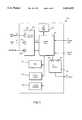
- FIG. 1is a block diagram of a partially fault resilient system.
- FIG. 2is a block diagram of system software of the system of FIG. 1.
- FIG. 3is a flowchart of a procedure used by an IOP Monitor of the system software of FIG. 2.
- FIG. 4is a block diagram of an IPI module of the system of FIG. 1.
- FIG. 5is a state transition table for the system of FIG. 1.
- FIG. 6is a block diagram of a fault resilient system.
- FIG. 7is a block diagram of a distributed fault resilient system.
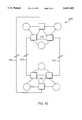
- FIG. 8is a block diagram of a fault tolerant system.
- FIG. 9is flowchart of a fault diagnosis procedure used by IOPs of the system of FIG. 8.
- FIG. 10is a block diagram of a disaster tolerant system.
- a fault resilient system 10includes an I/O processor (“IOP") 12 and two computing elements (“CEs”) 14a, 14b (collectively referred to as CEs 14). Because system 10 includes only a single IOP 12 and therefore cannot recover from a failure in IOP 12, system 10 is not entirely fault resilient.
- IOPI/O processor
- CEs 14a, 14bcomputing elements
- IOP 12includes two inter-processor interconnect (“IPI") modules 16a, 16b that are connected, respectively, to corresponding IPI modules 18a, 18b of CEs 14 by cables 20a, 20b.
- IOP 12also includes a processor 22, a memory system 24, two hard disk drives 26, 28, and a power supply 30.
- each CE 14includes a processor 32, a memory system 34, and a power supply 36. Separate power supplies 36 are used to ensure fault resilience in the event of a power supply failure.
- Processors 32a, 32bare "identical" to each other in that, for every instruction, the number of cycles required for processor 32a to perform an instruction is identical to the number of cycles required for processor 32b to perform the same instruction.
- system 10has been implemented using standard Intel 486 based motherboards for processors 22, 32 and four megabytes of memory for each of memory systems 24, 34.
- IOP 12 and CEs 14 of system 10run unmodified operating system and applications software, with hard drive 26 being used as the boot disk for the IOP and hard drive 28 being used as the boot disk for CEs 14.
- hard drive 26being used as the boot disk for the IOP
- hard drive 28being used as the boot disk for CEs 14.
- each hard drivewould also be duplicated.
- the operating system for IOP 12 and CEs 14is DOS. However, other operating systems can also be used. Moreover, IOP 12 can run a different operating system from the one run by CEs 14. For example, IOP 12 could run Unix while CEs 14 run DOS. This approach is advantageous because it allows CEs 14 to access peripherals from operating systems that do not support the peripherals. For example, if CEs 14 were running an operating system that did not support CD-ROM drives, and IOP 12 were running one that did, CEs 14 could access the CD-ROM drive by issuing I/O requests identical to those used to, say, access a hard drive. IOP 12 would then handle the translation of the I/O request to one suitable for accessing the CD-ROM drive.
- system 10includes specialized system software 40 that controls the booting and synchronization of CEs 14, disables local time in CEs 14, redirects all I/O requests from CEs 14 to IOP 12 for execution, and returns the results of the I/O requests, if any, from IOP 12 to CEs 14.
- System software 40includes two sets of IPI BIOS 42 that are ROM-based and are each located in the IPI module 18 of a CE 14. IPI BIOS 42 are used in bootup and synchronization activities. When a CE 14 is booted, IPI BIOS 42 replaces the I/O interrupt addresses in the system BIOS interrupt table with addresses that are controlled by CE Drivers 44. The interrupt addresses that are replaced include those corresponding to video services, fixed disk services, serial communications services, keyboard services, and time of day services.
- IPI BIOS 42also disables normal memory refreshing to ensure that memory refreshing, which affects the number of cycles during which a CE 14 is actually processing, is controlled by system software 40.
- Memory refreshingis required to maintain memory integrity.
- memoryis refreshed periodically, with one block of memory being refreshed at the end of each refresh period. The duration of the refresh period is selected so that the entire memory is refreshed within the memory's refresh limit. Thus, for example, if a memory has 256 blocks and an 8 ms refresh limit, then the refresh period is 31.25 ⁇ s (8 ms/256).
- IPI BIOS 42disables memory refreshing by placing a counter used in the Intel 486 motherboard to control memory refreshing in a mode that requires a gate input to the counter to change in order to increment. Because the gate input is typically connected to the power supply, the gate input never changes and the counter is effectively disabled.
- CE Drivers 44 of system software 40handle memory refreshing by burst refreshing multiple blocks of memory each time that an I/O request or quantum interrupt is generated.
- CE Drivers 44are stored on CE boot disk 28 and are run by CEs 14. In addition to performing burst memory refreshes, CE Drivers 44 intercept I/O requests to the system BIOS and redirects them through IPI modules 18 to IOP 12 for execution. CE Drivers 44 also respond to interrupt requests from IPI modules 18, disable the system clock, and, based on information supplied by IOP Monitor 48, control the time of day of CEs 14.
- An IOP Driver 46that is located on IOP boot disk 26 and is run by IOP 12 handles I/O requests from CEs 14 by redirecting them to an IOP Monitor 48 for processing and transmitting the results from IOP Monitor 48 to CEs 14.
- IOP Driver 46communicates with CE drivers 44 using a packet protocol.
- IOP Monitor 48is located on IOP boot disk 26 and is run by IOP 12. IOP Monitor 48 controls system 10 and performs the actual I/O requests to produce the results that are transmitted by IOP Driver 46 to CEs 14.
- System software 40also includes console software 49 that runs on IOP 12 and provides for user control of system 10. Using console software 49, a user can reset, boot, or synchronize a CE 14. The user can also set one or both of CEs 14 to automatically boot (autoboot) and/or automatically synchronize (autosync) after being reset or upon startup. The ability to control each CE 14 is useful both during normal operation and for test purposes.
- console software 49the user can also place system 10 into either an integrity mode in which IOP Monitor 48 shuts down both CEs 14 when faced with a miscompare error, a first availability mode in which IOP Monitor 48 disables CE 14a when faced with a miscompare error, or a second availability mode in which IOP Monitor 48 disables CE 14b when faced with a miscompare error.
- console software 49allows the user to request the status of system 10.
- console software 49could be implemented using a separate processor that communicates with IOP 12.
- Each CE 14runs a copy of the same application and the same operating system as that run by the other CE 14. Moreover, the contents of memory systems 34a and 34b are the same, and the operating context of CEs 14 are the same at each synchronization time. Thus, IOP Monitor 48 should receive identical sequences of I/O requests from CEs 14.
- IOP Monitor 48processes and monitors I/O requests according to a procedure 100. Initially, IOP Monitor 48 waits for an I/O request from one of CEs 14 (step 102). Upon receiving an I/O request packet from, for example, CE 14b, IOP Monitor 48 waits for either an I/O request from CE 14a or for the expiration of a timeout period (step 104). Because system 10 uses the DOS operating system, which halts execution of an application while an I/O request is being processed, IOP Monitor 48 is guaranteed not to receive an I/O request from CE 14b while waiting (step 104) for the I/O request from the CE 14a.
- IOP Monitor 48checks to determine whether the timeout period has expired (step 106). If not (that is, an I/O request packet from CE 14a has arrived), IOP Monitor 48 compares the checksums of the packets (step 108), and, if the checksums are equal, processes the I/O request (step 110). After processing the I/O request, IOP Monitor 48 issues a request to the system BIOS of IOP 12 for the current time of day (step 112).
- IOP Monitor 48After receiving the time of day, IOP Monitor 48 assembles an IPI packet that includes the time of day and the results, if any, of the I/O request (step 114) and sends the IPI packet to IOP Driver 46 (step 116) for transmission to CEs 14.
- CEs 14When CEs 14 receive the IPI packet, they use the transmitted time of day to update their local clocks which, as already noted, are otherwise disabled.
- execution in CEs 14is suspended until IOP Monitor 48 returns the results of the I/O request through IOP Driver 46. Because, before execution is resumed, the times of day of both CEs 14 are updated to a common value (the transmitted time of day from the IPI packet), the CEs 14 are kept in time synchronization with the transmitted time of day being designated the meta time. If a multitasking operating system were employed, execution in CEs 14 would not be suspended while IOP Monitor 48 performed the I/O request. Instead, processing in CEs 14 would be suspended only until receipt of an acknowledgement indicating that IOP Monitor 48 has begun processing the I/O request (step 110). The acknowledgement would include the time of day and would be used by CEs 14 to update the local clocks.
- IOP Monitor 48After sending the IPI packet to IOP Driver 46, IOP Monitor 48 verifies that both of CEs 14 are online (step 118), and, if so, waits for another I/O request from one of CEs 14 (step 102).
- IOP Monitor 48disables the CE 14 that failed to respond (step 119) and processes the I/O request (step 110).
- IOP Monitor 48checks to see if system 10 is operating in an availability mode or an integrity mode (step 120).
- IOP Monitor 48If system 10 is operating in an availability mode, IOP Monitor 48 disables the appropriate CE 14 based on the selected availability mode (step 122), and processes the I/O request (step 110). Thereafter, when IOP Monitor 48 checks whether both CEs 14 are online (step 118), and assuming that the disabled CE 14 has not been repaired and reactivated, IOP Monitor 48 then waits for an I/O request from the online CE 14 (step 124). Because system 10 is no longer fault resilient, when an I/O request is received, IOP Monitor 48 immediately processes the I/O request (step 110).
- IOP Monitor 48disables both CEs 14 (step 126) and stops processing (step 128).
- CE 14awhen the application or the operating system of, for example, CE 14a makes a non-I/O call to the system BIOS, the system BIOS executes the request and returns the results to the application without invoking system software 40. However, if the application or the operating system makes an I/O BIOS call, CE Driver 44a intercepts the I/O request. After intercepting the I/O request, CE Driver 44a packages the I/O request into an IPI packet and transmits the IPI packet to IOP 12.
- IPI module 16a of IOP 12When IPI module 16a of IOP 12 detects transmission of an IPI packet from CE 14a, IPI module 16a generates an interrupt to IOP Driver 16. IOP Driver 46 then reads the IPI packet.
- IOP Monitor 48responds to the IPI packet from CE 14a according to procedure 100. As also discussed, assuming that there are no hardware faults, IOP Driver 46 eventually transmits an IPI packet that contains the results of the I/O request and the time of day to CEs 14.
- IPI modules 18 of CEs 14receive the IPI packet from IOP 12.
- CE Drivers 44unpack the IPI packet, update the time of day of CEs 14, and return control of CEs 14 to the application or the operating system running on CEs 14.
- IPI Monitor 48treats the quantum interrupt IPI packet as an IPI packet without an I/O request.
- IOP Monitor 48detects the incoming quantum interrupt IPI packet (step 102 of FIG. 3) and, if a matching quantum interrupt IPI packet is received from the other CE 14 (steps 104, 106, and 108 of FIG. 3), issues a request to the system BIOS of IOP 12 for the current time of day (step 112 of FIG. 3).
- IOP Monitor 48then packages the current time of day into a quantum response IPI packet (step 114 of FIG. 3) that IOP Driver 46 then sends to CEs 14 (step 116 of FIG. 3).
- CE Drivers 44respond to the quantum response IPI packet by updating the time of day and returning control of CEs 14 to the application or the operating system running on CEs 14.
- IOP Monitor 48If IOP Monitor 48 does not receive a quantum interrupt IPI package from the other CE 14 within a predefined timeout period (step 106 of FIG. 3), IOP Monitor 48 responds by disabling the non-responding CE 14.
- IPI modules 16, 18 and cables 20provide all of the hardware necessary to produce a fault resilient system from the standard Intel 486 based motherboards used to implement processors 22, 32.
- an IPI module 18includes a control logic 50 that communicates I/O requests and responses between the system bus of a processor 32 of a CE 14 and a parallel interface 52 of IPI module 18.
- Parallel interface 52communicates with the parallel interface of an IPI module 16 through a cable 20.
- Parallel interface 52includes a sixteen bit data output port 54, a sixteen bit data input port 56, and a control port 58.
- Cable 20is configured so that data output port 54 is connected to the data input port of the IPI module 16, data input port 56 is connected to the data output port of the IPI module 16, and control port 58 is connected to the control port of the IPI module 16.
- Control port 58implements a handshaking protocol between IPI module 18 and the IPI module 16.
- Control logic 50is also connected to an IPI BIOS ROM 60. At startup, control logic 50 transfers IPI BIOS 42 (FIG. 2), the contents of IPI BIOS ROM 60, to processor 32 through the system bus of processor 32.
- a QI counter 62also located on IPI module 18, generates quantum interrupts as discussed above.
- QI counter 62includes a clock input 64 that is connected to the system clock of processor 32 and a gate input 66 that is connected to control logic 50. Gate input 66 is used to activate and reset the counter value of QI counter 62. When activated, QI counter 62 decrements the counter value by one during each cycle of the system clock of processor 32. When the counter value reaches zero, QI counter 62 generates a quantum interrupt that, as discussed above, activates CE Driver 44 (FIG. 2).
- CE Driver 44deactivates QI counter 62 at the beginning of each I/O transaction.
- CE Driver 44deactivates QI counter 62 by requesting an I/O write at a first address, known as the QI deactivation address.
- Control logic 50detects the I/O write request and deactivates QI counter 62 through gate input 66. Because this particular I/O write is for control purposes only, control logic 50 does not pass the I/O write to parallel interface 52.
- CE Driver 44resets and activates QI counter 62 by requesting an I/O write to a second address, known as the QI activation address.
- Control logic 50responds by resetting and activating QI counter 62.
- quantum interruptsare generated through use of debugging or other features available in processor 32.
- Some commonly available processorsinclude debugging or trap instructions that trap errors by transferring control of the processor to a designated program after the completion of a selected number of instructions following the trap instruction.
- CE Driver 44issues a trap instruction to indicate that control of processor 32 should be given to CE Driver 44 upon completion of, for example, 300 instructions.
- the trap instructioncauses control of processor 32 to be returned to CE Driver 44.
- CE Driver 44issues an instruction that cancels the trap instruction.
- IPI Module 18is also used in activating an offline CE 14. As discussed below, before an offline CE 14 is activated, the contents of the memory system 34 of the active CE 14 are copied into the memory system 34 of the offline CE 14. To minimize the effects of this copying on the active CE 14, the processor 32 of the active CE 14 is permitted to continue processing and the memory is copied only during cycles in which the system bus of the processor 32 of the active CE 14 is not in use.
- IPI module 18accounts for memory writes by the processor 32 to addresses that have already been copied to the offline CE 14. To do so, control logic 50 monitors the system bus and, when the processor 32 writes to a memory address that has already been copied, stores the address in a FIFO 68. When the memory transfer is complete, or when FIFO 68 is full, the contents of memory locations associated with the memory addresses stored in FIFO 68 are copied to the offline CE 14 and FIFO 68 is emptied. In other approaches, FIFO 68 is modified to store both memory addresses and the contents of memory locations associated with the addresses, or to store the block addresses of memory blocks to which memory addresses being written belong.
- IPI module 18also handles non-BIOS I/O requests.
- the BIOSis too slow to effectively perform I/O operations such as video display.
- some less structured or less disciplined operating systemssuch as DOS or UNIX, allow applications to circumvent the BIOS and make non-BIOS I/O requests by directly reading from or writing to the addresses associated with I/O devices.
- These non-BIOS I/O requestswhich cannot be intercepted by changing the system interrupt table, as is done in connection with, for example, I/O disk reads and writes, are problematic for a system in which synchronization requires tight control of the I/O interface.
- IPI module 18includes virtual I/O devices that mimic the hardware interfaces of physical I/O devices. These virtual I/O devices include a virtual display 70 and a virtual keyboard 72. As needed, other virtual I/O devices such as a virtual mouse or virtual serial and parallel ports could also be used.
- control logic 50monitors the system bus for read or write operations directed to addresses associated with non-BIOS I/O requests to system I/O devices. When control logic 50 detects such an operation, control logic 50 stores the information necessary to reconstruct the operation in the appropriate virtual device. Thus, for example, when control logic 50 detects a write operation directed to an address associated with the display, control logic 50 stores the information necessary to reconstruct the operation in virtual display 70.
- CE Driver 44scans the virtual I/O devices and, if the virtual devices are not empty, assembles the information stored in the virtual devices into an IPI packet and transmits the IPI packet to IOP 12.
- IOP 12treats the packet like a BIOS I/O request using procedure 100 discussed above.
- control logic 50detects a read addressed to a virtual I/O device, control logic 50 assembles the read request into an IPI packet for handling by IOP 12.
- IOP 12treats the IPI packet like a standard BIOS I/O request.
- each CE 14always operates in one of eight states and, because there are only a limited number of permissible state combinations, system 10 always operates in one of fourteen states.
- the major CE operating statesare OFFLINE, RTB (ready to boot), BOOTING, ACTIVE, RTS (ready to sync), WAITING, M -- SYNC, (synchronizing as master), and S -- SYNC (synchronizing as slave).
- IOP Monitor 48changes the operating states of CEs 14 based on the state of system 10 and user commands from console software 49. Through console software 49, a user can reset a CE 14 at any time. Whenever the user resets a CE 14, or a fault occurs in the CE 14, IOP Monitor 48 changes the state of the CE 14 to OFFLINE.
- system 10is operating with both CEs 14 OFFLINE (state 150).
- System 10operates in the upper states of FIG. 5 (states 152-162) when CE 14a becomes operational before CE 14b and in the lower states (states 166-176) when CE 14b is the first to become operational. If CEs 14 become operational simultaneously, the first operational CE 14 to be recognized by IOP Monitor 48 is treated as the first to become operational.
- the state of the CE 14changes to RTB if the CE 14 is not set to autoboot or to BOOTING if the CE 14 is set to autoboot. For example, if CE 14a issues a boot request when both CEs 14 are OFFLINE, and CE 14a is not set to autoboot, then the state of CE 14a changes to RTB (state 152). Thereafter, IOP Monitor 48 waits for the user, through console software 49, to boot CE 14a. When the user boots CE 14a, the state of CE 14a changes to BOOTING (state 154). If the user resets CE 14a, the state of CE 14a changes to OFFLINE (state 150).
- CE 14aIf both CEs 14 are OFFLINE when CE 14a issues a boot request, and CE 14a is set to autoboot, the state of CE 14a changes to BOOTING (state 154). If CE 14a boots successfully, the state of CE 14a changes to ACTIVE (state 156).
- CE 14aWhen CE 14a is ACTIVE, and CE 14b issues a boot request, or if CE 14b had issued a boot request while the state of CE 14a was transitioning from OFFLINE to ACTIVE (states 152-156), the state of CE 14b changes to RTS (state 158) if CE 14b is set to autosync and otherwise to WAITING (state 160). If the state of CE 14b changes to RTS (state 158), IOP Monitor waits for the user to issue a synchronize command to CE 14b. When the user issues such a command, the state of CE 14b changes to WAITING (state 160).
- IOP Monitor 48copies the contents of memory system 34a of CE 14a into memory system 34b of CE 14b. Once the memory transfer is complete, IOP Monitor 48 waits for CE 14a to transmit a quantum interrupt or I/O request IPI packet. Upon receipt of such a packet, IOP Monitor 48 changes the state of CE 14a to M -- SYNC and the state of CE 14b to S -- SYNC (state 162), and synchronizes the CEs 14. This synchronization includes responding to any memory changes that occurred while IOP Monitor 48 was waiting for CE 14a to transmit a quantum interrupt or I/O request IPI packet. Upon completion of the synchronization, the states of the CEs 14 both change to ACTIVE (state 164) and system 10 is deemed to be fully operational.
- IOP Monitor 48does not wait for memory transfer to complete before changing the state of CE 14a to M -- SYNC and the state of CE 14b to S -- SYNC (state 162). Instead, IOP Monitor 48 makes this state change upon receipt of an IPI packet from CE 14a and performs the memory transfer as part of the synchronization process.
- CE 14bSimilar state transitions occur when CE 14b is the first CE 14 to issue a boot request. Thus, assuming that CE 14b is not set to autoboot, CE 14b transitions from OFFLINE (state 150) to RTC (state 166) to BOOTING (state 168) to ACTIVE (state 170). Similarly, once CE 14b is ACTIVE, and assuming that CE 14a is not set to autosync, CE 14a transitions from OFFLINE (state 170) to RTS (state 172) to WAITING (state 174) to S -- SYNC (state 176) to ACTIVE (state 164).
- a fault resilient system 200includes two IOPs 202 and two CEs 204.
- Each CE 204is connected, through an IPI card 206 and a cable 208, to an IPI card 210 of each IOP 202.
- IOPs 202are redundantly connected to each other through IPI cards 210 and cables 212. Because every component of system 200 has a redundant backup component, system 200 is entirely fault resilient.
- cables 208 and 210could be replaced by a pair of local area networks to which each IOP 202 and CE 204 would be connected. Indeed, local area networks can always be substituted for cable connections.
- System 200is operating system and application software independent in that it does not require modifications of the operating system or the application software to operate. Any single piece of hardware can be upgraded or repaired in system 200 with no service interruption. Therefore, by sequentially replacing each piece of hardware and allowing system 200 to resynchronize after each replacement, the hardware of system 200 can be replaced in its entirety without service interruption. Similarly, software on system 200 can be upgraded with minimal service interruption (that is, during the software upgrade, the application will become unavailable for an acceptable period of time such as two seconds). Also, disaster tolerance for purposes of availability can be obtained by placing each IOP/CE pair in a separate location and connecting the pairs through a communications link.
- a distributed, high performance, fault resilient system 220includes two systems 200, the IOPs 202 of which are connected to each other, through IPI modules, by cables 222.
- System 220uses distributed computing environment software to achieve high performance by running separate portions of an application on each system 200.
- System 220is fault tolerant and offers the ability to perform both hardware and software upgrades without service interruption.
- a fault tolerant system 230includes three IOPs (232, 234, and 236) and three CEs (238, 240, and 242). Through IPI modules 244 and cables 246, each IOP is connected to an IPI module 244 of each of the other IOPs. Through IPI modules 248 and cables 250, each CE is connected to an IPI module 244 of two of the IOPs, with CE 238 being connected to IOPs 232 and 234, CE 240 being connected to IOPs 232 and 236, and CE 242 being connected to IOPs 234 and 236. Like system 200, system 230 allows for hardware upgrades without service interruption and software upgrades with only minimal service interruption.
- system 230is more capable of identifying the source of a hardware fault than is system 10. Thus, while system 10 simply disables one or both of CEs 14 when an error is detected, system 230 offers a higher degree of fault diagnosis.
- each IOP (232, 234, 236) of system 230performs fault diagnosis according to a procedure 300. Initially, each IOP (232, 234, 236) checks for major faults such as power loss, broken cables, and nonfunctional CEs or IOPs using well known techniques such as power sensing, cable sensing, and protocol timeouts (step 302). When such a fault is detected, each IOP disables the faulty device or, if necessary, the entire system.
- major faultssuch as power loss, broken cables, and nonfunctional CEs or IOPs using well known techniques such as power sensing, cable sensing, and protocol timeouts.
- each IOPwaits to receive IPI packets (that is, quantum interrupts or I/O requests) from the two CEs to which the IOP is connected (step 304).
- IPI packetsthat is, quantum interrupts or I/O requests
- IOP 232waits to receive IPI packets from CEs 238 and 240.
- each IOPtransmits the checksums ("CRCs") of those IPI packets to the other two IOPs and waits for receipt of CRCs from the other two IOPs (step 306).
- CRCschecksums
- each lOPAfter receiving the CRCs from the other two lOPs, each lOP generates a three by three matrix in which each column corresponds to a CE, each row corresponds to an lOP, and each entry is the CRC received from the column's CE by the row's IOP (step 308).
- IOP 232generates the following matrix:
- IOP 232After generating the matrix, IOP 232 sums the entries in each row and each column of the matrix. If the three row sums are equal and the three column sums are equal (step 310), then there is no fault and IOP 232 checks again for major faults (step 302).
- IOP 232compares the CRC entries in each of the columns of the matrix. If the two CRC entries in each column match (step 312), then IOP 232 diagnoses that a CE failure has occurred and disables the CE corresponding to the column for which the sum does not equal the sums of the other columns (step 314).
- IOP 232determines how many of the columns include mismatched entries. If the matrix includes only one column with mismatched entries (step 315), then IOP 232 diagnoses that the path between the IOP corresponding to the matrix row sum that is unequal to the other matrix row sums and the CE corresponding to the column having mismatched entries has failed and disables that path (step 316). For purposes of the diagnosis, the path includes the IPI module 244 in the IOP, the IPI module 248 in the CE, and the cable 250.
- IOP 232confirms that one matrix row sum is unequal to the other matrix row sums, diagnoses an IOP failure, and disables the IOP corresponding to the matrix row sum that is unequal to the other matrix row sums (step 318).
- IOP 232determines that system 300 still includes sufficient non-faulty hardware to remain operational, IOP 232 checks again for major faults (step 302). Because system 230 is triply redundant, system 230 can continue to operate even after several components have failed. For example, to remain operating in an availability mode, system 230 only needs to have a single functional CE, a single functional IOP, and a functional path between the two.
- each IOP(232, 234, 236) can correctly diagnose any single failure in a fully operational system 230 or in a system 230 in which one element (that is, a CE, an IOP, or a path) has previously been disabled.
- each IOPaccounts for CRCs that are not received because of the disabled element by using values that appear to be correct in comparison to actually received CRCs.
- Procedure 300is not dependent on the particular arrangement of interconnections between the CEs and IOPs. To operate properly, procedure 300 only requires that the output of each CE be directly monitored by at least two IOPs. Thus, procedure 300 could be implemented in a system using any interconnect mechanism and does not require point to point connections between the CEs and IOPs. For example, the CEs and IOPs could be connected to at least two local area networks. In an alternative approach, instead of summing the CRC values in the rows and columns of the matrix, these values can be compared and those rows or columns in which the entries do not match can be marked with a match/mismatch indicator.
- each IOP 202 of system 200generates a two by two matrix in which each column corresponds to a CE 204 and each row corresponds to a IOP 202:
- each IOP 202After generating the matrix, each IOP 202 attaches a mismatch indicator to each row or column in which the two entries are mismatched.
- an IOP 202has faulted. Depending on the operating mode of system 200, an IOP 202 either disables another IOP 202 or shuts down system 200.
- the IOP 202 to be disabledis selected based on user supplied parameters similar to the two availability modes used in system 10.
- IOPs 202respond by disabling a CE 204 if system 200 is operating in an availability mode or, if system 200 is operating in an integrity mode, shutting down system 200. If both rows and one column have mismatch indicators, then one of the paths between the IOPs 202 and the CE 204 corresponding to the mismatched column has failed. Depending on the operating mode of system 200, IOPs 202 either disable the CE 204 having the failed path or shut down system 200. If both rows and both column have mismatch indicators, then multiple faults exist and IOPs 202 shut down system 200.
- the IOP 202 corresponding to the mismatched rowhas faulted. Depending on the operating mode of system 200, the other IOP 202 either disables the faulty IOP 202 or shuts down system 200. If one row and one column have mismatch indicators, then the path between the IOP 202 corresponding to the mismatched row and the CE 204 corresponding to the mismatched column has failed. Depending on the operating mode of system 200, IOPs 202 either account for the failed path in future processing or shut down system 200.
- a disaster tolerant system 260includes two fault tolerant systems 230 located in remote locations and connected by communications link 262, such as Ethernet or fiber, and operating in meta time lockstep with each other. To obtain meta time lockstep, all IPI packets are transmitted between fault tolerant systems 230. Like system 220, system 260 allows for hardware and software upgrades without service interruption.
- the paired modular redundant architecture of the inventionallows for varying levels of fault resilience and fault tolerance through use of CEs that operate asynchronously in real time and are controlled by IOPs to operate synchronously in meta time.
- This architectureis simple and cost-effective, and can be expanded or upgraded with minimal difficulty.
Landscapes
- Engineering & Computer Science (AREA)
- Theoretical Computer Science (AREA)
- Physics & Mathematics (AREA)
- General Engineering & Computer Science (AREA)
- General Physics & Mathematics (AREA)
- Quality & Reliability (AREA)
- Hardware Redundancy (AREA)
- Multi Processors (AREA)
- Test And Diagnosis Of Digital Computers (AREA)
Abstract
Description
______________________________________ CE 238CE 240CE 242 ______________________________________ IOP 232 CRCCRC X IOP 234 CRC X CRC IOP 236 X CRC CRC ______________________________________
______________________________________ CE 204CE 204 ______________________________________IOP 202CRC CRC IOP 202 CRC CRC ______________________________________
Claims (5)
Priority Applications (3)
| Application Number | Priority Date | Filing Date | Title |
|---|---|---|---|
| US08/537,985US5615403A (en) | 1993-12-01 | 1995-10-02 | Method for executing I/O request by I/O processor after receiving trapped memory address directed to I/O device from all processors concurrently executing same program |
| US08/768,437US5956474A (en) | 1993-12-01 | 1996-12-18 | Fault resilient/fault tolerant computing |
| US08/934,747US6038685A (en) | 1993-12-01 | 1997-09-22 | Fault resilient/fault tolerant computing |
Applications Claiming Priority (2)
| Application Number | Priority Date | Filing Date | Title |
|---|---|---|---|
| US15978393A | 1993-12-01 | 1993-12-01 | |
| US08/537,985US5615403A (en) | 1993-12-01 | 1995-10-02 | Method for executing I/O request by I/O processor after receiving trapped memory address directed to I/O device from all processors concurrently executing same program |
Related Parent Applications (1)
| Application Number | Title | Priority Date | Filing Date |
|---|---|---|---|
| US15978393AContinuation | 1993-12-01 | 1993-12-01 |
Related Child Applications (1)
| Application Number | Title | Priority Date | Filing Date |
|---|---|---|---|
| US08/768,437DivisionUS5956474A (en) | 1993-12-01 | 1996-12-18 | Fault resilient/fault tolerant computing |
Publications (1)
| Publication Number | Publication Date |
|---|---|
| US5615403Atrue US5615403A (en) | 1997-03-25 |
Family
ID=22574001
Family Applications (4)
| Application Number | Title | Priority Date | Filing Date |
|---|---|---|---|
| US08/405,193Expired - LifetimeUS5600784A (en) | 1993-12-01 | 1995-03-16 | Fault resilient/fault tolerant computing |
| US08/537,985Expired - LifetimeUS5615403A (en) | 1993-12-01 | 1995-10-02 | Method for executing I/O request by I/O processor after receiving trapped memory address directed to I/O device from all processors concurrently executing same program |
| US08/768,437Expired - LifetimeUS5956474A (en) | 1993-12-01 | 1996-12-18 | Fault resilient/fault tolerant computing |
| US08/934,747Expired - LifetimeUS6038685A (en) | 1993-12-01 | 1997-09-22 | Fault resilient/fault tolerant computing |
Family Applications Before (1)
| Application Number | Title | Priority Date | Filing Date |
|---|---|---|---|
| US08/405,193Expired - LifetimeUS5600784A (en) | 1993-12-01 | 1995-03-16 | Fault resilient/fault tolerant computing |
Family Applications After (2)
| Application Number | Title | Priority Date | Filing Date |
|---|---|---|---|
| US08/768,437Expired - LifetimeUS5956474A (en) | 1993-12-01 | 1996-12-18 | Fault resilient/fault tolerant computing |
| US08/934,747Expired - LifetimeUS6038685A (en) | 1993-12-01 | 1997-09-22 | Fault resilient/fault tolerant computing |
Country Status (6)
| Country | Link |
|---|---|
| US (4) | US5600784A (en) |
| EP (4) | EP0986007A3 (en) |
| AU (4) | AU680974B2 (en) |
| CA (1) | CA2177850A1 (en) |
| DE (3) | DE69435165D1 (en) |
| WO (1) | WO1995015529A1 (en) |
Cited By (36)
| Publication number | Priority date | Publication date | Assignee | Title |
|---|---|---|---|---|
| US5896523A (en)* | 1997-06-04 | 1999-04-20 | Marathon Technologies Corporation | Loosely-coupled, synchronized execution |
| WO1999066405A1 (en)* | 1998-06-15 | 1999-12-23 | Sun Microsystems, Inc. | Processor bridge with dissimilar data access |
| WO1999066403A1 (en)* | 1998-06-15 | 1999-12-23 | Sun Microsystems, Inc. | Processor bridge with dissimilar data registers |
| US6029255A (en)* | 1996-12-26 | 2000-02-22 | Kabushiki Kaisha Toshiba | Input/output control device and method applied to fault-resilient computer system |
| US6038685A (en)* | 1993-12-01 | 2000-03-14 | Marathon Technologies Corporation | Fault resilient/fault tolerant computing |
| WO2000079404A1 (en)* | 1999-06-23 | 2000-12-28 | Advanced Micro Devices, Inc. | Minimizing use of bus command code points to request the start and end of a lock |
| US6185662B1 (en) | 1997-12-22 | 2001-02-06 | Nortel Networks Corporation | High availability asynchronous computer system |
| US6279119B1 (en) | 1997-11-14 | 2001-08-21 | Marathon Technologies Corporation | Fault resilient/fault tolerant computing |
| US20020144175A1 (en)* | 2001-03-28 | 2002-10-03 | Long Finbarr Denis | Apparatus and methods for fault-tolerant computing using a switching fabric |
| US6687851B1 (en)* | 2000-04-13 | 2004-02-03 | Stratus Technologies Bermuda Ltd. | Method and system for upgrading fault-tolerant systems |
| US6691225B1 (en) | 2000-04-14 | 2004-02-10 | Stratus Technologies Bermuda Ltd. | Method and apparatus for deterministically booting a computer system having redundant components |
| US20040199813A1 (en)* | 2003-02-28 | 2004-10-07 | Maxwell Technologies, Inc. | Self-correcting computer |
| US6820213B1 (en) | 2000-04-13 | 2004-11-16 | Stratus Technologies Bermuda, Ltd. | Fault-tolerant computer system with voter delay buffer |
| US20050223275A1 (en)* | 2004-03-30 | 2005-10-06 | Jardine Robert L | Performance data access |
| US20050223274A1 (en)* | 2004-03-30 | 2005-10-06 | Bernick David L | Method and system executing user programs on non-deterministic processors |
| US20060020852A1 (en)* | 2004-03-30 | 2006-01-26 | Bernick David L | Method and system of servicing asynchronous interrupts in multiple processors executing a user program |
| US20060143528A1 (en)* | 2004-12-27 | 2006-06-29 | Stratus Technologies Bermuda Ltd | Systems and methods for checkpointing |
| US20060150006A1 (en)* | 2004-12-21 | 2006-07-06 | Nec Corporation | Securing time for identifying cause of asynchronism in fault-tolerant computer |
| US20060168425A1 (en)* | 2005-01-25 | 2006-07-27 | Del Vigna Paul Jr | Method and system of aligning execution point of duplicate copies of a user program by exchanging information about instructions executed |
| US20060168434A1 (en)* | 2005-01-25 | 2006-07-27 | Del Vigna Paul Jr | Method and system of aligning execution point of duplicate copies of a user program by copying memory stores |
| US20060242456A1 (en)* | 2005-04-26 | 2006-10-26 | Kondo Thomas J | Method and system of copying memory from a source processor to a target processor by duplicating memory writes |
| US20060242461A1 (en)* | 2005-04-26 | 2006-10-26 | Kondo Thomas J | Method and system of copying a memory area between processor elements for lock-step execution |
| US20070006166A1 (en)* | 2005-06-20 | 2007-01-04 | Seagate Technology Llc | Code coverage for an embedded processor system |
| US20070038891A1 (en)* | 2005-08-12 | 2007-02-15 | Stratus Technologies Bermuda Ltd. | Hardware checkpointing system |
| US20070043972A1 (en)* | 2005-08-19 | 2007-02-22 | Stratus Technologies Bermuda Ltd. | Systems and methods for split mode operation of fault-tolerant computer systems |
| US20080196037A1 (en)* | 2007-02-13 | 2008-08-14 | Thales | Process for maintaining execution synchronization between several asynchronous processors working in parallel and in a redundant manner |
| US20090076628A1 (en)* | 2007-09-18 | 2009-03-19 | David Mark Smith | Methods and apparatus to upgrade and provide control redundancy in process plants |
| US20090083735A1 (en)* | 2007-09-26 | 2009-03-26 | Kabushiki Kaisha Toshiba | High availability system and execution state control method |
| EP1675003A3 (en)* | 2004-12-21 | 2010-02-24 | NEC Corporation | Fault tolerant system and controller, operation method, and operation program used in the fault tolerant system |
| US8443230B1 (en)* | 2010-12-15 | 2013-05-14 | Xilinx, Inc. | Methods and systems with transaction-level lockstep |
| US8799706B2 (en) | 2004-03-30 | 2014-08-05 | Hewlett-Packard Development Company, L.P. | Method and system of exchanging information between processors |
| US9251002B2 (en) | 2013-01-15 | 2016-02-02 | Stratus Technologies Bermuda Ltd. | System and method for writing checkpointing data |
| US9588844B2 (en) | 2013-12-30 | 2017-03-07 | Stratus Technologies Bermuda Ltd. | Checkpointing systems and methods using data forwarding |
| US9652338B2 (en) | 2013-12-30 | 2017-05-16 | Stratus Technologies Bermuda Ltd. | Dynamic checkpointing systems and methods |
| US9760442B2 (en) | 2013-12-30 | 2017-09-12 | Stratus Technologies Bermuda Ltd. | Method of delaying checkpoints by inspecting network packets |
| US10063567B2 (en) | 2014-11-13 | 2018-08-28 | Virtual Software Systems, Inc. | System for cross-host, multi-thread session alignment |
Families Citing this family (92)
| Publication number | Priority date | Publication date | Assignee | Title |
|---|---|---|---|---|
| US6233702B1 (en)* | 1992-12-17 | 2001-05-15 | Compaq Computer Corporation | Self-checked, lock step processor pairs |
| US5978565A (en)* | 1993-07-20 | 1999-11-02 | Vinca Corporation | Method for rapid recovery from a network file server failure including method for operating co-standby servers |
| SE506739C2 (en)* | 1995-09-29 | 1998-02-09 | Ericsson Telefon Ab L M | Operation and maintenance of clock distribution networks with redundancy |
| US5819020A (en)* | 1995-10-16 | 1998-10-06 | Network Specialists, Inc. | Real time backup system |
| FR2748136B1 (en)* | 1996-04-30 | 1998-07-31 | Sextant Avionique | ELECTRONIC MODULE WITH REDUNDANT ARCHITECTURE FOR FUNCTIONALITY INTEGRITY CONTROL |
| US5793943A (en)* | 1996-07-29 | 1998-08-11 | Micron Electronics, Inc. | System for a primary BIOS ROM recovery in a dual BIOS ROM computer system |
| US5790397A (en)* | 1996-09-17 | 1998-08-04 | Marathon Technologies Corporation | Fault resilient/fault tolerant computing |
| US5892897A (en)* | 1997-02-05 | 1999-04-06 | Motorola, Inc. | Method and apparatus for microprocessor debugging |
| US6161202A (en)* | 1997-02-18 | 2000-12-12 | Ee-Signals Gmbh & Co. Kg | Method for the monitoring of integrated circuits |
| US7389312B2 (en)* | 1997-04-28 | 2008-06-17 | Emc Corporation | Mirroring network data to establish virtual storage area network |
| US5983371A (en)* | 1997-07-11 | 1999-11-09 | Marathon Technologies Corporation | Active failure detection |
| FR2767935B1 (en)* | 1997-09-04 | 1999-11-12 | Bull Sa | METHOD FOR SYNCHRONIZING A COMPUTER SYSTEM AND COMPUTER SYSTEM THUS SYNCHRONIZED |
| US6289022B1 (en)* | 1997-10-21 | 2001-09-11 | The Foxboro Company | Methods and systems for fault-tolerant data transmission |
| US6374364B1 (en)* | 1998-01-20 | 2002-04-16 | Honeywell International, Inc. | Fault tolerant computing system using instruction counting |
| DE19815263C2 (en)* | 1998-04-04 | 2002-03-28 | Astrium Gmbh | Device for fault-tolerant execution of programs |
| US6256753B1 (en) | 1998-06-30 | 2001-07-03 | Sun Microsystems, Inc. | Bus error handling in a computer system |
| US6974787B2 (en) | 1998-08-31 | 2005-12-13 | Exxonmobil Corporation | Gasoline sulfur reduction in fluid catalytic cracking |
| US20020153283A1 (en)* | 1998-12-28 | 2002-10-24 | Arthur W Chester | Gasoline sulfur reduction in fluid catalytic cracking |
| US6321279B1 (en)* | 1998-09-14 | 2001-11-20 | Compaq Computer Corporation | System for implementing intelligent I/O processing in a multi-processor system by redirecting I/O messages to a target central processor selected from the multi-processor system |
| US6219828B1 (en)* | 1998-09-30 | 2001-04-17 | International Business Machines Corporation | Method for using two copies of open firmware for self debug capability |
| WO2000036492A2 (en)* | 1998-12-18 | 2000-06-22 | Triconex Corporation | Method and apparatus for processing control using a multiple redundant processor control system |
| US7803267B2 (en)* | 1998-12-28 | 2010-09-28 | W. R. Grace & Co.-Conn. | Gasoline sulfur reduction in fluid catalytic cracking |
| US6324692B1 (en)* | 1999-07-28 | 2001-11-27 | Data General Corporation | Upgrade of a program |
| US6735716B1 (en)* | 1999-09-27 | 2004-05-11 | Cisco Technology, Inc. | Computerized diagnostics and failure recovery |
| FR2803057B1 (en)* | 1999-12-22 | 2002-11-29 | Centre Nat Etd Spatiales | COMPUTER SYSTEM TOLERANT TO TRANSIENT ERRORS AND MANAGEMENT METHOD IN SUCH A SYSTEM |
| US6735715B1 (en) | 2000-04-13 | 2004-05-11 | Stratus Technologies Bermuda Ltd. | System and method for operating a SCSI bus with redundant SCSI adaptors |
| AU2001293360A1 (en)* | 2000-04-13 | 2001-10-30 | Stratus Technologies International, S.A.R.L. | Method and system for upgrading fault-tolerant systems |
| US6633996B1 (en) | 2000-04-13 | 2003-10-14 | Stratus Technologies Bermuda Ltd. | Fault-tolerant maintenance bus architecture |
| US6691257B1 (en) | 2000-04-13 | 2004-02-10 | Stratus Technologies Bermuda Ltd. | Fault-tolerant maintenance bus protocol and method for using the same |
| US6708283B1 (en) | 2000-04-13 | 2004-03-16 | Stratus Technologies, Bermuda Ltd. | System and method for operating a system with redundant peripheral bus controllers |
| US6813721B1 (en) | 2000-09-20 | 2004-11-02 | Stratus Computer Systems, S.A.R.L. | Methods and apparatus for generating high-frequency clocks deterministically from a low-frequency system reference clock |
| US6718474B1 (en) | 2000-09-21 | 2004-04-06 | Stratus Technologies Bermuda Ltd. | Methods and apparatus for clock management based on environmental conditions |
| ATE371328T1 (en)* | 2000-10-30 | 2007-09-15 | Siemens Ag | HIGH-SPEED CONNECTION FOR EMBEDDED SYSTEMS IN A COMPUTER NETWORK |
| US7213265B2 (en)* | 2000-11-15 | 2007-05-01 | Lockheed Martin Corporation | Real time active network compartmentalization |
| US7225467B2 (en) | 2000-11-15 | 2007-05-29 | Lockheed Martin Corporation | Active intrusion resistant environment of layered object and compartment keys (airelock) |
| US6801876B2 (en)* | 2000-12-08 | 2004-10-05 | Caterpillar Inc | Method and apparatus of managing time for a processing system |
| GB2370380B (en) | 2000-12-19 | 2003-12-31 | Picochip Designs Ltd | Processor architecture |
| US6948010B2 (en) | 2000-12-20 | 2005-09-20 | Stratus Technologies Bermuda Ltd. | Method and apparatus for efficiently moving portions of a memory block |
| EP1231537A1 (en)* | 2001-02-09 | 2002-08-14 | Siemens Aktiengesellschaft | Automatic turn-on of a computer cluster after a curable failure |
| US6766479B2 (en) | 2001-02-28 | 2004-07-20 | Stratus Technologies Bermuda, Ltd. | Apparatus and methods for identifying bus protocol violations |
| US6928583B2 (en)* | 2001-04-11 | 2005-08-09 | Stratus Technologies Bermuda Ltd. | Apparatus and method for two computing elements in a fault-tolerant server to execute instructions in lockstep |
| US6996750B2 (en)* | 2001-05-31 | 2006-02-07 | Stratus Technologies Bermuda Ltd. | Methods and apparatus for computer bus error termination |
| JP2004046455A (en)* | 2002-07-10 | 2004-02-12 | Nec Corp | Information processor |
| JP3982353B2 (en)* | 2002-07-12 | 2007-09-26 | 日本電気株式会社 | Fault tolerant computer apparatus, resynchronization method and resynchronization program |
| JP2004046599A (en) | 2002-07-12 | 2004-02-12 | Nec Corp | Fault tolerant computer apparatus, resynchronization method and resynchronization program |
| EP1398699A1 (en)* | 2002-09-12 | 2004-03-17 | Siemens Aktiengesellschaft | Method for synchronizing events, in particular for fault-tolerant systems |
| US7080094B2 (en)* | 2002-10-29 | 2006-07-18 | Lockheed Martin Corporation | Hardware accelerated validating parser |
| US7146643B2 (en)* | 2002-10-29 | 2006-12-05 | Lockheed Martin Corporation | Intrusion detection accelerator |
| US20070061884A1 (en)* | 2002-10-29 | 2007-03-15 | Dapp Michael C | Intrusion detection accelerator |
| US20040083466A1 (en)* | 2002-10-29 | 2004-04-29 | Dapp Michael C. | Hardware parser accelerator |
| US7507686B2 (en)* | 2002-12-03 | 2009-03-24 | W. R. Grace & Co. - Conn. | Gasoline sulfur reduction in fluid catalytic cracking |
| GB2396446B (en)* | 2002-12-20 | 2005-11-16 | Picochip Designs Ltd | Array synchronization |
| US7320084B2 (en) | 2003-01-13 | 2008-01-15 | Sierra Logic | Management of error conditions in high-availability mass-storage-device shelves by storage-shelf routers |
| CA2521576A1 (en)* | 2003-02-28 | 2004-09-16 | Lockheed Martin Corporation | Hardware accelerator state table compiler |
| US20050010811A1 (en)* | 2003-06-16 | 2005-01-13 | Zimmer Vincent J. | Method and system to support network port authentication from out-of-band firmware |
| US20050039074A1 (en)* | 2003-07-09 | 2005-02-17 | Tremblay Glenn A. | Fault resilient/fault tolerant computing |
| US7146530B2 (en)* | 2003-07-18 | 2006-12-05 | Hewlett-Packard Development Company, L.P. | Targeted fault tolerance by special CPU instructions |
| DE102004005680A1 (en)* | 2004-02-05 | 2005-08-25 | Bayerische Motoren Werke Ag | Device and method for controlling control units in a vehicle electrical system of a motor vehicle |
| US7321985B2 (en)* | 2004-02-26 | 2008-01-22 | International Business Machines Corporation | Method for achieving higher availability of computer PCI adapters |
| DE102004011933B4 (en)* | 2004-03-11 | 2008-04-10 | Dr.Ing.H.C. F. Porsche Ag | Power take-off device for a track-guided toy vehicle |
| JP4182948B2 (en)* | 2004-12-21 | 2008-11-19 | 日本電気株式会社 | Fault tolerant computer system and interrupt control method therefor |
| JP3897046B2 (en)* | 2005-01-28 | 2007-03-22 | 横河電機株式会社 | Information processing apparatus and information processing method |
| US7424641B2 (en)* | 2005-04-06 | 2008-09-09 | Delphi Technologies, Inc. | Control system and method for validating operation of the control system |
| JP4816911B2 (en)* | 2006-02-07 | 2011-11-16 | 日本電気株式会社 | Memory synchronization method and refresh control circuit |
| US8032889B2 (en) | 2006-04-05 | 2011-10-04 | Maxwell Technologies, Inc. | Methods and apparatus for managing and controlling power consumption and heat generation in computer systems |
| US7549085B2 (en)* | 2006-04-28 | 2009-06-16 | Hewlett-Packard Development Company, L.P. | Method and apparatus to insert special instruction |
| DE102006032726B4 (en)* | 2006-07-14 | 2008-05-15 | Lucas Automotive Gmbh | Method for synchronizing components of a motor vehicle brake system and electronic brake control system |
| US8689224B2 (en)* | 2007-09-26 | 2014-04-01 | The Boeing Company | Methods and systems for preserving certified software through virtualization |
| GB2454865B (en)* | 2007-11-05 | 2012-06-13 | Picochip Designs Ltd | Power control |
| US8255732B2 (en)* | 2008-05-28 | 2012-08-28 | The United States Of America, As Represented By The Administrator Of The National Aeronautics And Space Administration | Self-stabilizing byzantine-fault-tolerant clock synchronization system and method |
| GB2466661B (en)* | 2009-01-05 | 2014-11-26 | Intel Corp | Rake receiver |
| DE102009000045A1 (en)* | 2009-01-07 | 2010-07-08 | Robert Bosch Gmbh | Method and device for operating a control device |
| US20100229029A1 (en)* | 2009-03-06 | 2010-09-09 | Frazier Ii Robert Claude | Independent and dynamic checkpointing system and method |
| JP5278530B2 (en)* | 2009-03-09 | 2013-09-04 | 富士通株式会社 | Information processing apparatus, information processing apparatus control method, and information processing apparatus control program |
| GB2470037B (en) | 2009-05-07 | 2013-07-10 | Picochip Designs Ltd | Methods and devices for reducing interference in an uplink |
| GB2470891B (en) | 2009-06-05 | 2013-11-27 | Picochip Designs Ltd | A method and device in a communication network |
| GB2470771B (en) | 2009-06-05 | 2012-07-18 | Picochip Designs Ltd | A method and device in a communication network |
| US20110078498A1 (en)* | 2009-09-30 | 2011-03-31 | United States Of America As Represented By The Administrator Of The National Aeronautics And Spac | Radiation-hardened hybrid processor |
| US20110099421A1 (en)* | 2009-09-30 | 2011-04-28 | Alessandro Geist | Radiation-hardened hybrid processor |
| GB2474071B (en) | 2009-10-05 | 2013-08-07 | Picochip Designs Ltd | Femtocell base station |
| GB2482869B (en) | 2010-08-16 | 2013-11-06 | Picochip Designs Ltd | Femtocell access control |
| WO2012058597A1 (en) | 2010-10-28 | 2012-05-03 | Maxwell Technologies, Inc. | System, method and apparatus for error correction in multi-processor systems |
| GB2489716B (en) | 2011-04-05 | 2015-06-24 | Intel Corp | Multimode base system |
| GB2489919B (en) | 2011-04-05 | 2018-02-14 | Intel Corp | Filter |
| GB2491098B (en) | 2011-05-16 | 2015-05-20 | Intel Corp | Accessing a base station |
| US8966478B2 (en) | 2011-06-28 | 2015-02-24 | The Boeing Company | Methods and systems for executing software applications using hardware abstraction |
| US8856590B2 (en)* | 2012-01-07 | 2014-10-07 | Compunetix, Inc. | Reliable compute engine, method and apparatus |
| US20170322521A1 (en)* | 2014-12-09 | 2017-11-09 | General Electric Company | Redundant ethernet-based control apparatus and method |
| US10025344B2 (en) | 2015-04-21 | 2018-07-17 | The United States Of America As Represented By The Administrator Of Nasa | Self-stabilizing distributed symmetric-fault tolerant synchronization protocol |
| WO2019173075A1 (en)* | 2018-03-06 | 2019-09-12 | DinoplusAI Holdings Limited | Mission-critical ai processor with multi-layer fault tolerance support |
| US10642826B1 (en) | 2018-08-30 | 2020-05-05 | Gravic, Inc. | Mixed-mode method for combining active/active and validation architectures utilizing a check integrity module |
| US11899547B2 (en) | 2021-11-30 | 2024-02-13 | Mellanox Technologies, Ltd. | Transaction based fault tolerant computing system |
Citations (35)
| Publication number | Priority date | Publication date | Assignee | Title |
|---|---|---|---|---|
| US4270168A (en)* | 1978-08-31 | 1981-05-26 | United Technologies Corporation | Selective disablement in fail-operational, fail-safe multi-computer control system |
| US4356546A (en)* | 1980-02-05 | 1982-10-26 | The Bendix Corporation | Fault-tolerant multi-computer system |
| US4358823A (en)* | 1977-03-25 | 1982-11-09 | Trw, Inc. | Double redundant processor |
| US4449182A (en)* | 1981-10-05 | 1984-05-15 | Digital Equipment Corporation | Interface between a pair of processors, such as host and peripheral-controlling processors in data processing systems |
| US4531185A (en)* | 1983-08-31 | 1985-07-23 | International Business Machines Corporation | Centralized synchronization of clocks |
| US4622667A (en)* | 1984-11-27 | 1986-11-11 | Sperry Corporation | Digital fail operational automatic flight control system utilizing redundant dissimilar data processing |
| US4634110A (en)* | 1983-07-28 | 1987-01-06 | Harris Corporation | Fault detection and redundancy management system |
| US4695945A (en)* | 1985-02-28 | 1987-09-22 | International Business Machines Corporation | Processor I/O and interrupt filters allowing a co-processor to run software unknown to the main processor |
| US4812968A (en)* | 1986-11-12 | 1989-03-14 | International Business Machines Corp. | Method for controlling processor access to input/output devices |
| US4823256A (en)* | 1984-06-22 | 1989-04-18 | American Telephone And Telegraph Company, At&T Bell Laboratories | Reconfigurable dual processor system |
| EP0327083A2 (en)* | 1988-02-05 | 1989-08-09 | Licentia Patent-Verwaltungs-GmbH | Device to operate absolute time clocks in a process control system comprising a central clock and participants |
| US4907228A (en)* | 1987-09-04 | 1990-03-06 | Digital Equipment Corporation | Dual-rail processor with error checking at single rail interfaces |
| US4910663A (en)* | 1987-07-10 | 1990-03-20 | Tandem Computers Incorporated | System for measuring program execution by replacing an executable instruction with interrupt causing instruction |
| US4916704A (en)* | 1987-09-04 | 1990-04-10 | Digital Equipment Corporation | Interface of non-fault tolerant components to fault tolerant system |
| US4920481A (en)* | 1986-04-28 | 1990-04-24 | Xerox Corporation | Emulation with display update trapping |
| US4933940A (en)* | 1987-04-15 | 1990-06-12 | Allied-Signal Inc. | Operations controller for a fault tolerant multiple node processing system |
| EP0372580A2 (en)* | 1987-11-09 | 1990-06-13 | Tandem Computers Incorporated | Synchronization of fault-tolerant computer system having multiple processors |
| US4937741A (en)* | 1988-04-28 | 1990-06-26 | The Charles Stark Draper Laboratory, Inc. | Synchronization of fault-tolerant parallel processing systems |
| US4965717A (en)* | 1988-12-09 | 1990-10-23 | Tandem Computers Incorporated | Multiple processor system having shared memory with private-write capability |
| US5005174A (en)* | 1987-09-04 | 1991-04-02 | Digital Equipment Corporation | Dual zone, fault tolerant computer system with error checking in I/O writes |
| US5048022A (en)* | 1989-08-01 | 1991-09-10 | Digital Equipment Corporation | Memory device with transfer of ECC signals on time division multiplexed bidirectional lines |
| US5062042A (en)* | 1986-04-28 | 1991-10-29 | Xerox Corporation | System for managing data which is accessible by file address or disk address via a disk track map |
| US5091847A (en)* | 1989-10-03 | 1992-02-25 | Grumman Aerospace Corporation | Fault tolerant interface station |
| US5095423A (en)* | 1990-03-27 | 1992-03-10 | Sun Microsystems, Inc. | Locking mechanism for the prevention of race conditions |
| US5099485A (en)* | 1987-09-04 | 1992-03-24 | Digital Equipment Corporation | Fault tolerant computer systems with fault isolation and repair |
| US5166674A (en)* | 1990-02-02 | 1992-11-24 | International Business Machines Corporation | Multiprocessing packet switching connection system having provision for error correction and recovery |
| US5222215A (en)* | 1991-08-29 | 1993-06-22 | International Business Machines Corporation | Cpu expansive gradation of i/o interruption subclass recognition |
| US5226152A (en)* | 1990-12-07 | 1993-07-06 | Motorola, Inc. | Functional lockstep arrangement for redundant processors |
| US5239641A (en)* | 1987-11-09 | 1993-08-24 | Tandem Computers Incorporated | Method and apparatus for synchronizing a plurality of processors |
| US5249187A (en)* | 1987-09-04 | 1993-09-28 | Digital Equipment Corporation | Dual rail processors with error checking on I/O reads |
| US5251312A (en)* | 1991-12-30 | 1993-10-05 | Sun Microsystems, Inc. | Method and apparatus for the prevention of race conditions during dynamic chaining operations |
| US5261092A (en)* | 1990-09-26 | 1993-11-09 | Honeywell Inc. | Synchronizing slave processors through eavesdrop by one on periodic sync-verify messages directed to another followed by comparison of individual status |
| US5327553A (en)* | 1989-12-22 | 1994-07-05 | Tandem Computers Incorporated | Fault-tolerant computer system with /CONFIG filesystem |
| US5339404A (en)* | 1991-05-28 | 1994-08-16 | International Business Machines Corporation | Asynchronous TMR processing system |
| US5367639A (en)* | 1991-12-30 | 1994-11-22 | Sun Microsystems, Inc. | Method and apparatus for dynamic chaining of DMA operations without incurring race conditions |
Family Cites Families (12)
| Publication number | Priority date | Publication date | Assignee | Title |
|---|---|---|---|---|
| US3864670A (en)* | 1970-09-30 | 1975-02-04 | Yokogawa Electric Works Ltd | Dual computer system with signal exchange system |
| US4228496A (en)* | 1976-09-07 | 1980-10-14 | Tandem Computers Incorporated | Multiprocessor system |
| DE2939935A1 (en)* | 1979-09-28 | 1981-04-09 | Licentia Patent-Verwaltungs-Gmbh, 6000 Frankfurt | SECURE DATA PROCESSING DEVICE |
| US4939643A (en)* | 1981-10-01 | 1990-07-03 | Stratus Computer, Inc. | Fault tolerant digital data processor with improved bus protocol |
| AU606854B2 (en)* | 1986-01-10 | 1991-02-21 | Wyse Technology, Inc. | Virtual peripheral controller |
| US4807228A (en)* | 1987-03-18 | 1989-02-21 | American Telephone And Telegraph Company, At&T Bell Laboratories | Method of spare capacity use for fault detection in a multiprocessor system |
| US5065310A (en)* | 1989-05-10 | 1991-11-12 | International Business Machines Corporation | Reducing cache-reload transient at a context swap |
| US5295258A (en)* | 1989-12-22 | 1994-03-15 | Tandem Computers Incorporated | Fault-tolerant computer system with online recovery and reintegration of redundant components |
| US5155845A (en)* | 1990-06-15 | 1992-10-13 | Storage Technology Corporation | Data storage system for providing redundant copies of data on different disk drives |
| EP0496927B1 (en)* | 1991-02-01 | 1997-01-08 | Siemens Aktiengesellschaft | Procedure for restarting the multiprocessor computer of a telecommunications switching system after a failure |
| US5448723A (en)* | 1993-10-15 | 1995-09-05 | Tandem Computers Incorporated | Method and apparatus for fault tolerant connection of a computing system to local area networks |
| EP0986007A3 (en)* | 1993-12-01 | 2001-11-07 | Marathon Technologies Corporation | Method of isolating I/O requests |
- 1994
- 1994-11-15EPEP99122244Apatent/EP0986007A3/ennot_activeWithdrawn
- 1994-11-15DEDE69435165Tpatent/DE69435165D1/ennot_activeExpired - Lifetime
- 1994-11-15DEDE69424565Tpatent/DE69424565T2/ennot_activeExpired - Lifetime
- 1994-11-15AUAU11820/95Apatent/AU680974B2/ennot_activeCeased
- 1994-11-15WOPCT/US1994/013350patent/WO1995015529A1/enactiveIP Right Grant
- 1994-11-15DEDE69435090Tpatent/DE69435090T2/ennot_activeExpired - Fee Related
- 1994-11-15EPEP95902615Apatent/EP0731945B1/ennot_activeExpired - Lifetime
- 1994-11-15CACA002177850Apatent/CA2177850A1/ennot_activeAbandoned
- 1994-11-15EPEP99122245Apatent/EP0974912B1/ennot_activeExpired - Lifetime
- 1994-11-15EPEP99122243Apatent/EP0986008B1/ennot_activeExpired - Lifetime
- 1995
- 1995-03-16USUS08/405,193patent/US5600784A/ennot_activeExpired - Lifetime
- 1995-10-02USUS08/537,985patent/US5615403A/ennot_activeExpired - Lifetime
- 1996
- 1996-12-18USUS08/768,437patent/US5956474A/ennot_activeExpired - Lifetime
- 1997
- 1997-09-22USUS08/934,747patent/US6038685A/ennot_activeExpired - Lifetime
- 1997-10-24AUAU42864/97Apatent/AU711456B2/ennot_activeCeased
- 1997-10-24AUAU42865/97Apatent/AU711435B2/ennot_activeCeased
- 1997-10-24AUAU42866/97Apatent/AU711419B2/ennot_activeCeased
Patent Citations (42)
| Publication number | Priority date | Publication date | Assignee | Title |
|---|---|---|---|---|
| US4358823A (en)* | 1977-03-25 | 1982-11-09 | Trw, Inc. | Double redundant processor |
| US4270168A (en)* | 1978-08-31 | 1981-05-26 | United Technologies Corporation | Selective disablement in fail-operational, fail-safe multi-computer control system |
| US4356546A (en)* | 1980-02-05 | 1982-10-26 | The Bendix Corporation | Fault-tolerant multi-computer system |
| US4449182A (en)* | 1981-10-05 | 1984-05-15 | Digital Equipment Corporation | Interface between a pair of processors, such as host and peripheral-controlling processors in data processing systems |
| US4449182B1 (en)* | 1981-10-05 | 1989-12-12 | ||
| US4634110A (en)* | 1983-07-28 | 1987-01-06 | Harris Corporation | Fault detection and redundancy management system |
| US4531185A (en)* | 1983-08-31 | 1985-07-23 | International Business Machines Corporation | Centralized synchronization of clocks |
| US4823256A (en)* | 1984-06-22 | 1989-04-18 | American Telephone And Telegraph Company, At&T Bell Laboratories | Reconfigurable dual processor system |
| US4622667A (en)* | 1984-11-27 | 1986-11-11 | Sperry Corporation | Digital fail operational automatic flight control system utilizing redundant dissimilar data processing |
| US4695945A (en)* | 1985-02-28 | 1987-09-22 | International Business Machines Corporation | Processor I/O and interrupt filters allowing a co-processor to run software unknown to the main processor |
| US4920481A (en)* | 1986-04-28 | 1990-04-24 | Xerox Corporation | Emulation with display update trapping |
| US5062042A (en)* | 1986-04-28 | 1991-10-29 | Xerox Corporation | System for managing data which is accessible by file address or disk address via a disk track map |
| US4812968A (en)* | 1986-11-12 | 1989-03-14 | International Business Machines Corp. | Method for controlling processor access to input/output devices |
| US4933940A (en)* | 1987-04-15 | 1990-06-12 | Allied-Signal Inc. | Operations controller for a fault tolerant multiple node processing system |
| US4910663A (en)* | 1987-07-10 | 1990-03-20 | Tandem Computers Incorporated | System for measuring program execution by replacing an executable instruction with interrupt causing instruction |
| US4907228A (en)* | 1987-09-04 | 1990-03-06 | Digital Equipment Corporation | Dual-rail processor with error checking at single rail interfaces |
| US4916704A (en)* | 1987-09-04 | 1990-04-10 | Digital Equipment Corporation | Interface of non-fault tolerant components to fault tolerant system |
| US5255367A (en)* | 1987-09-04 | 1993-10-19 | Digital Equipment Corporation | Fault tolerant, synchronized twin computer system with error checking of I/O communication |
| US5005174A (en)* | 1987-09-04 | 1991-04-02 | Digital Equipment Corporation | Dual zone, fault tolerant computer system with error checking in I/O writes |
| US5249187A (en)* | 1987-09-04 | 1993-09-28 | Digital Equipment Corporation | Dual rail processors with error checking on I/O reads |
| US5099485A (en)* | 1987-09-04 | 1992-03-24 | Digital Equipment Corporation | Fault tolerant computer systems with fault isolation and repair |
| EP0372580A2 (en)* | 1987-11-09 | 1990-06-13 | Tandem Computers Incorporated | Synchronization of fault-tolerant computer system having multiple processors |
| US5317726A (en)* | 1987-11-09 | 1994-05-31 | Tandem Computers Incorporated | Multiple-processor computer system with asynchronous execution of identical code streams |
| US5239641A (en)* | 1987-11-09 | 1993-08-24 | Tandem Computers Incorporated | Method and apparatus for synchronizing a plurality of processors |
| EP0327083A2 (en)* | 1988-02-05 | 1989-08-09 | Licentia Patent-Verwaltungs-GmbH | Device to operate absolute time clocks in a process control system comprising a central clock and participants |
| US4937741A (en)* | 1988-04-28 | 1990-06-26 | The Charles Stark Draper Laboratory, Inc. | Synchronization of fault-tolerant parallel processing systems |
| US5276823A (en)* | 1988-12-09 | 1994-01-04 | Tandem Computers Incorporated | Fault-tolerant computer system with redesignation of peripheral processor |
| US5193175A (en)* | 1988-12-09 | 1993-03-09 | Tandem Computers Incorporated | Fault-tolerant computer with three independently clocked processors asynchronously executing identical code that are synchronized upon each voted access to two memory modules |
| US4965717B1 (en)* | 1988-12-09 | 1993-05-25 | Tandem Computers Inc | |
| US5146589A (en)* | 1988-12-09 | 1992-09-08 | Tandem Computers Incorporated | Refresh control for dynamic memory in multiple processor system |
| US4965717A (en)* | 1988-12-09 | 1990-10-23 | Tandem Computers Incorporated | Multiple processor system having shared memory with private-write capability |
| US5048022A (en)* | 1989-08-01 | 1991-09-10 | Digital Equipment Corporation | Memory device with transfer of ECC signals on time division multiplexed bidirectional lines |
| US5091847A (en)* | 1989-10-03 | 1992-02-25 | Grumman Aerospace Corporation | Fault tolerant interface station |
| US5327553A (en)* | 1989-12-22 | 1994-07-05 | Tandem Computers Incorporated | Fault-tolerant computer system with /CONFIG filesystem |
| US5166674A (en)* | 1990-02-02 | 1992-11-24 | International Business Machines Corporation | Multiprocessing packet switching connection system having provision for error correction and recovery |
| US5095423A (en)* | 1990-03-27 | 1992-03-10 | Sun Microsystems, Inc. | Locking mechanism for the prevention of race conditions |
| US5261092A (en)* | 1990-09-26 | 1993-11-09 | Honeywell Inc. | Synchronizing slave processors through eavesdrop by one on periodic sync-verify messages directed to another followed by comparison of individual status |
| US5226152A (en)* | 1990-12-07 | 1993-07-06 | Motorola, Inc. | Functional lockstep arrangement for redundant processors |
| US5339404A (en)* | 1991-05-28 | 1994-08-16 | International Business Machines Corporation | Asynchronous TMR processing system |
| US5222215A (en)* | 1991-08-29 | 1993-06-22 | International Business Machines Corporation | Cpu expansive gradation of i/o interruption subclass recognition |
| US5251312A (en)* | 1991-12-30 | 1993-10-05 | Sun Microsystems, Inc. | Method and apparatus for the prevention of race conditions during dynamic chaining operations |
| US5367639A (en)* | 1991-12-30 | 1994-11-22 | Sun Microsystems, Inc. | Method and apparatus for dynamic chaining of DMA operations without incurring race conditions |
Non-Patent Citations (10)
| Title |
|---|
| "Low Cost Device For Contention-Free Barrier Synchronization," IBM Technical Disclosure Bulletin, vol. 31, No. 11, Apr. 1989, Armonk, NY, pp. 382-389. |
| IMP, Integrated Micro Products, XM RISC Fault Tolerant Computer System, Oct. 1992.* |
| IMP, Integrated Micro Products, XM-RISC Fault Tolerant Computer System, Oct. 1992. |
| International Search Report dated May 3, 1995.* |
| Low Cost Device For Contention Free Barrier Synchronization, IBM Technical Disclosure Bulletin, vol. 31, No. 11, Apr. 1989, Armonk, NY, pp. 382 389.* |
| PCT Written Opinion dated Sep. 13, 1995.* |
| Siewiorek et al., "Reliable Computer Systems Design and Evaluation", Digital Press 1992, pp. 618-622. |
| Siewiorek et al., Reliable Computer Systems Design and Evaluation , Digital Press 1992, pp. 618 622.* |
| Williams, "New approach allows painless move to fault tolerance", Computer Design, May 1992. |
| Williams, New approach allows painless move to fault tolerance , Computer Design, May 1992.* |
Cited By (60)
| Publication number | Priority date | Publication date | Assignee | Title |
|---|---|---|---|---|
| US6038685A (en)* | 1993-12-01 | 2000-03-14 | Marathon Technologies Corporation | Fault resilient/fault tolerant computing |
| US6029255A (en)* | 1996-12-26 | 2000-02-22 | Kabushiki Kaisha Toshiba | Input/output control device and method applied to fault-resilient computer system |
| US5896523A (en)* | 1997-06-04 | 1999-04-20 | Marathon Technologies Corporation | Loosely-coupled, synchronized execution |
| US6279119B1 (en) | 1997-11-14 | 2001-08-21 | Marathon Technologies Corporation | Fault resilient/fault tolerant computing |
| US6473869B2 (en) | 1997-11-14 | 2002-10-29 | Marathon Technologies Corporation | Fault resilient/fault tolerant computing |
| AU753120B2 (en)* | 1997-11-14 | 2002-10-10 | Marathon Technologies Corporation | Fault resilient/fault tolerant computing |
| US6185662B1 (en) | 1997-12-22 | 2001-02-06 | Nortel Networks Corporation | High availability asynchronous computer system |
| US6366985B1 (en) | 1997-12-22 | 2002-04-02 | Nortel Networks Limited | High availability asynchronous computer system |
| WO1999066403A1 (en)* | 1998-06-15 | 1999-12-23 | Sun Microsystems, Inc. | Processor bridge with dissimilar data registers |
| US6138198A (en)* | 1998-06-15 | 2000-10-24 | Sun Microsystems, Inc. | Processor bridge with dissimilar data registers which is operable to disregard data differences for dissimilar data write accesses |
| US6141718A (en)* | 1998-06-15 | 2000-10-31 | Sun Microsystems, Inc. | Processor bridge with dissimilar data registers which is operable to disregard data differences for dissimilar data direct memory accesses |
| WO1999066405A1 (en)* | 1998-06-15 | 1999-12-23 | Sun Microsystems, Inc. | Processor bridge with dissimilar data access |
| WO2000079404A1 (en)* | 1999-06-23 | 2000-12-28 | Advanced Micro Devices, Inc. | Minimizing use of bus command code points to request the start and end of a lock |
| US6430639B1 (en) | 1999-06-23 | 2002-08-06 | Advanced Micro Devices, Inc. | Minimizing use of bus command code points to request the start and end of a lock |
| US6820213B1 (en) | 2000-04-13 | 2004-11-16 | Stratus Technologies Bermuda, Ltd. | Fault-tolerant computer system with voter delay buffer |
| US6687851B1 (en)* | 2000-04-13 | 2004-02-03 | Stratus Technologies Bermuda Ltd. | Method and system for upgrading fault-tolerant systems |
| US6691225B1 (en) | 2000-04-14 | 2004-02-10 | Stratus Technologies Bermuda Ltd. | Method and apparatus for deterministically booting a computer system having redundant components |
| US20020144175A1 (en)* | 2001-03-28 | 2002-10-03 | Long Finbarr Denis | Apparatus and methods for fault-tolerant computing using a switching fabric |
| US7065672B2 (en) | 2001-03-28 | 2006-06-20 | Stratus Technologies Bermuda Ltd. | Apparatus and methods for fault-tolerant computing using a switching fabric |
| US20040199813A1 (en)* | 2003-02-28 | 2004-10-07 | Maxwell Technologies, Inc. | Self-correcting computer |
| US7890799B2 (en) | 2003-02-28 | 2011-02-15 | Maxwell Technologies, Inc. | Self-correcting computer |
| US7467326B2 (en) | 2003-02-28 | 2008-12-16 | Maxwell Technologies, Inc. | Self-correcting computer |
| US20080141057A1 (en)* | 2003-02-28 | 2008-06-12 | Maxwell Technologies, Inc. | Cache coherency during resynchronization of self-correcting computer |
| US7613948B2 (en) | 2003-02-28 | 2009-11-03 | Maxwell Technologies, Inc. | Cache coherency during resynchronization of self-correcting computer |
| US20050223274A1 (en)* | 2004-03-30 | 2005-10-06 | Bernick David L | Method and system executing user programs on non-deterministic processors |
| US20060020852A1 (en)* | 2004-03-30 | 2006-01-26 | Bernick David L | Method and system of servicing asynchronous interrupts in multiple processors executing a user program |
| US20050223275A1 (en)* | 2004-03-30 | 2005-10-06 | Jardine Robert L | Performance data access |
| US7434098B2 (en) | 2004-03-30 | 2008-10-07 | Hewlett-Packard Development Company, L.P. | Method and system of determining whether a user program has made a system level call |
| US8799706B2 (en) | 2004-03-30 | 2014-08-05 | Hewlett-Packard Development Company, L.P. | Method and system of exchanging information between processors |
| US7426656B2 (en) | 2004-03-30 | 2008-09-16 | Hewlett-Packard Development Company, L.P. | Method and system executing user programs on non-deterministic processors |
| US20050246587A1 (en)* | 2004-03-30 | 2005-11-03 | Bernick David L | Method and system of determining whether a user program has made a system level call |
| US20060150006A1 (en)* | 2004-12-21 | 2006-07-06 | Nec Corporation | Securing time for identifying cause of asynchronism in fault-tolerant computer |
| EP1675003A3 (en)* | 2004-12-21 | 2010-02-24 | NEC Corporation | Fault tolerant system and controller, operation method, and operation program used in the fault tolerant system |
| US7500139B2 (en)* | 2004-12-21 | 2009-03-03 | Nec Corporation | Securing time for identifying cause of asynchronism in fault-tolerant computer |
| US7496787B2 (en) | 2004-12-27 | 2009-02-24 | Stratus Technologies Bermuda Ltd. | Systems and methods for checkpointing |
| US20060143528A1 (en)* | 2004-12-27 | 2006-06-29 | Stratus Technologies Bermuda Ltd | Systems and methods for checkpointing |
| US7328331B2 (en) | 2005-01-25 | 2008-02-05 | Hewlett-Packard Development Company, L.P. | Method and system of aligning execution point of duplicate copies of a user program by copying memory stores |
| US20060168434A1 (en)* | 2005-01-25 | 2006-07-27 | Del Vigna Paul Jr | Method and system of aligning execution point of duplicate copies of a user program by copying memory stores |
| US7467327B2 (en) | 2005-01-25 | 2008-12-16 | Hewlett-Packard Development Company, L.P. | Method and system of aligning execution point of duplicate copies of a user program by exchanging information about instructions executed |
| US20060168425A1 (en)* | 2005-01-25 | 2006-07-27 | Del Vigna Paul Jr | Method and system of aligning execution point of duplicate copies of a user program by exchanging information about instructions executed |
| US7590885B2 (en) | 2005-04-26 | 2009-09-15 | Hewlett-Packard Development Company, L.P. | Method and system of copying memory from a source processor to a target processor by duplicating memory writes |
| US20060242456A1 (en)* | 2005-04-26 | 2006-10-26 | Kondo Thomas J | Method and system of copying memory from a source processor to a target processor by duplicating memory writes |
| US7933966B2 (en) | 2005-04-26 | 2011-04-26 | Hewlett-Packard Development Company, L.P. | Method and system of copying a memory area between processor elements for lock-step execution |
| US20060242461A1 (en)* | 2005-04-26 | 2006-10-26 | Kondo Thomas J | Method and system of copying a memory area between processor elements for lock-step execution |
| US20070006166A1 (en)* | 2005-06-20 | 2007-01-04 | Seagate Technology Llc | Code coverage for an embedded processor system |
| US20070038891A1 (en)* | 2005-08-12 | 2007-02-15 | Stratus Technologies Bermuda Ltd. | Hardware checkpointing system |
| US7669073B2 (en)* | 2005-08-19 | 2010-02-23 | Stratus Technologies Bermuda Ltd. | Systems and methods for split mode operation of fault-tolerant computer systems |
| US20070043972A1 (en)* | 2005-08-19 | 2007-02-22 | Stratus Technologies Bermuda Ltd. | Systems and methods for split mode operation of fault-tolerant computer systems |
| US8205201B2 (en)* | 2007-02-13 | 2012-06-19 | Thales | Process for maintaining execution synchronization between several asynchronous processors working in parallel and in a redundant manner |
| US20080196037A1 (en)* | 2007-02-13 | 2008-08-14 | Thales | Process for maintaining execution synchronization between several asynchronous processors working in parallel and in a redundant manner |
| US20090076628A1 (en)* | 2007-09-18 | 2009-03-19 | David Mark Smith | Methods and apparatus to upgrade and provide control redundancy in process plants |
| US9104638B2 (en) | 2007-09-26 | 2015-08-11 | Kabushiki Kaisha Toshiba | High availability system and execution state control method |
| US20090083735A1 (en)* | 2007-09-26 | 2009-03-26 | Kabushiki Kaisha Toshiba | High availability system and execution state control method |
| US8281304B2 (en) | 2007-09-26 | 2012-10-02 | Kabushiki Kaisha Toshiba | High availability system and execution state control method |
| US8443230B1 (en)* | 2010-12-15 | 2013-05-14 | Xilinx, Inc. | Methods and systems with transaction-level lockstep |
| US9251002B2 (en) | 2013-01-15 | 2016-02-02 | Stratus Technologies Bermuda Ltd. | System and method for writing checkpointing data |
| US9588844B2 (en) | 2013-12-30 | 2017-03-07 | Stratus Technologies Bermuda Ltd. | Checkpointing systems and methods using data forwarding |
| US9652338B2 (en) | 2013-12-30 | 2017-05-16 | Stratus Technologies Bermuda Ltd. | Dynamic checkpointing systems and methods |
| US9760442B2 (en) | 2013-12-30 | 2017-09-12 | Stratus Technologies Bermuda Ltd. | Method of delaying checkpoints by inspecting network packets |
| US10063567B2 (en) | 2014-11-13 | 2018-08-28 | Virtual Software Systems, Inc. | System for cross-host, multi-thread session alignment |
Also Published As
| Publication number | Publication date |
|---|---|
| AU711435B2 (en) | 1999-10-14 |
| JPH09509270A (en) | 1997-09-16 |
| AU4286697A (en) | 1998-01-15 |
| EP0731945B1 (en) | 2000-05-17 |
| EP0986008A3 (en) | 2000-07-19 |
| DE69435090D1 (en) | 2008-05-29 |
| AU680974B2 (en) | 1997-08-14 |
| US5956474A (en) | 1999-09-21 |
| DE69435165D1 (en) | 2008-12-18 |
| EP0974912A2 (en) | 2000-01-26 |
| DE69424565D1 (en) | 2000-06-21 |
| AU711419B2 (en) | 1999-10-14 |
| US6038685A (en) | 2000-03-14 |
| JP3679412B2 (en) | 2005-08-03 |
| EP0974912B1 (en) | 2008-11-05 |
| WO1995015529A1 (en) | 1995-06-08 |
| EP0986008A2 (en) | 2000-03-15 |
| DE69435090T2 (en) | 2009-06-10 |
| AU4286597A (en) | 1998-01-15 |
| EP0731945A4 (en) | 1997-02-12 |
| AU1182095A (en) | 1995-06-19 |
| EP0731945A1 (en) | 1996-09-18 |
| US5600784A (en) | 1997-02-04 |
| EP0986007A3 (en) | 2001-11-07 |
| EP0986008B1 (en) | 2008-04-16 |
| EP0986007A2 (en) | 2000-03-15 |
| CA2177850A1 (en) | 1995-06-08 |
| EP0974912A3 (en) | 2000-07-19 |
| AU711456B2 (en) | 1999-10-14 |
| AU4286497A (en) | 1998-01-15 |
| DE69424565T2 (en) | 2001-01-18 |
Similar Documents
| Publication | Publication Date | Title |
|---|---|---|
| US5615403A (en) | Method for executing I/O request by I/O processor after receiving trapped memory address directed to I/O device from all processors concurrently executing same program | |
| US5790397A (en) | Fault resilient/fault tolerant computing | |
| US6493796B1 (en) | Method and apparatus for maintaining consistency of data stored in a group of mirroring devices | |
| US5398331A (en) | Shared storage controller for dual copy shared data | |
| EP0306209B1 (en) | Dual rail processors with error checking at single rail interfaces | |
| US5005174A (en) | Dual zone, fault tolerant computer system with error checking in I/O writes | |
| US5249187A (en) | Dual rail processors with error checking on I/O reads | |
| EP0306244B1 (en) | Fault tolerant computer system with fault isolation | |
| EP0415546A2 (en) | Memory device | |
| JPH03184129A (en) | Conversion of specified data to system data | |
| JPH0934809A (en) | Highly reliable computer system | |
| JP3069585B2 (en) | Targeted reset method in data processing equipment | |
| JP3679412B6 (en) | Computation with fast recovery from failure / tolerance to failure | |
| JPH0916426A (en) | Fault-tolerant computer with a 2-port console | |
| JPH03184155A (en) | Processing of non-existence memory error | |
| AU7167300A (en) | Fault handling/fault tolerant computing | |
| Renaux | Fault Tolerance by a Distributed Software Control for a High Reliability |
Legal Events
| Date | Code | Title | Description |
|---|---|---|---|
| STCF | Information on status: patent grant | Free format text:PATENTED CASE | |
| FPAY | Fee payment | Year of fee payment:4 | |
| AS | Assignment | Owner name:GREEN MOUNTAIN CAPITAL, LP, VERMONT Free format text:SECURITY INTEREST;ASSIGNOR:MARATHON TECHNOLOGIES CORPORATION;REEL/FRAME:013552/0767 Effective date:20021016 Owner name:NORTHERN TECHNOLOGY PARTNERS II LLC, VERMONT Free format text:SECURITY AGREEMENT;ASSIGNOR:MARATHON TECHNOLOGIES CORPORATION;REEL/FRAME:013552/0758 Effective date:20020731 | |
| FPAY | Fee payment | Year of fee payment:8 | |
| AS | Assignment | Owner name:MARATHON TECHNOLOGIES CORPORATION, MASSACHUSETTS Free format text:RELEASE BY SECURED PARTY;ASSIGNOR:NORTHERN TECHNOLOGY PARTNERS II LLC;REEL/FRAME:017353/0335 Effective date:20040213 | |
| AS | Assignment | Owner name:MARATHON TECHNOLOGIES CORPORATION, MASSACHUSETTS Free format text:RELEASE BY SECURED PARTY;ASSIGNOR:GREEN MOUNTAIN CAPITAL, L.P.;REEL/FRAME:017366/0324 Effective date:20040213 | |
| FEPP | Fee payment procedure | Free format text:PAYOR NUMBER ASSIGNED (ORIGINAL EVENT CODE: ASPN); ENTITY STATUS OF PATENT OWNER: SMALL ENTITY | |
| FPAY | Fee payment | Year of fee payment:12 | |
| REMI | Maintenance fee reminder mailed | ||
| AS | Assignment | Owner name:WF FUND III LIMITED PARTNERSHIP (D/B/A WELLINGTON Free format text:SECURITY AGREEMENT;ASSIGNOR:MARATHON TECHNOLOGIES CORPORATION;REEL/FRAME:025413/0876 Effective date:20100715 | |
| AS | Assignment | Owner name:MARATHON TECHNOLOGIES CORPORATION, MASSACHUSETTS Free format text:RELEASE BY SECURED PARTY;ASSIGNOR:WF FUND III LIMTED PARTNERSHIP (D/B/A WELLINGTON FINANCIAL LP AND WF FINANCIAL FUND III);REEL/FRAME:026975/0179 Effective date:20110905 Owner name:CITRIX SYSTEMS, INC., FLORIDA Free format text:ASSIGNMENT OF ASSIGNORS INTEREST;ASSIGNOR:MARATHON TECHNOLOGIES CORPORATION;REEL/FRAME:026975/0827 Effective date:20110923 | |
| AS | Assignment | Owner name:STRATUS TECHNOLOGIES BERMUDA LTD., BERMUDA Free format text:ASSIGNMENT OF ASSIGNORS INTEREST;ASSIGNOR:CITRIX SYSTEMS, INC.;REEL/FRAME:029518/0502 Effective date:20120921 | |
| AS | Assignment | Owner name:SUNTRUST BANK, GEORGIA Free format text:SECURITY INTEREST;ASSIGNOR:STRATUS TECHNOLOGIES BERMUDA LTD.;REEL/FRAME:032776/0595 Effective date:20140428 |