US5615252A - System and apparatus for recording and displaying received information at a remote location - Google Patents
System and apparatus for recording and displaying received information at a remote locationDownload PDFInfo
- Publication number
- US5615252A US5615252AUS08/369,201US36920195AUS5615252AUS 5615252 AUS5615252 AUS 5615252AUS 36920195 AUS36920195 AUS 36920195AUS 5615252 AUS5615252 AUS 5615252A
- Authority
- US
- United States
- Prior art keywords
- packet
- premises
- transmission means
- information
- packet receiver
- Prior art date
- Legal status (The legal status is an assumption and is not a legal conclusion. Google has not performed a legal analysis and makes no representation as to the accuracy of the status listed.)
- Expired - Fee Related
Links
- 230000005540biological transmissionEffects0.000claimsabstractdescription35
- 238000004891communicationMethods0.000description12
- 230000006870functionEffects0.000description7
- 238000001514detection methodMethods0.000description4
- 238000010586diagramMethods0.000description3
- 230000007613environmental effectEffects0.000description2
- 230000002452interceptive effectEffects0.000description2
- 230000004044responseEffects0.000description2
- 230000009977dual effectEffects0.000description1
- 239000004973liquid crystal related substanceSubstances0.000description1
- 238000000034methodMethods0.000description1
- 230000006855networkingEffects0.000description1
- 230000008569processEffects0.000description1
- 238000002604ultrasonographyMethods0.000description1
- 230000000007visual effectEffects0.000description1
Images


Classifications
- H—ELECTRICITY
- H04—ELECTRIC COMMUNICATION TECHNIQUE
- H04M—TELEPHONIC COMMUNICATION
- H04M1/00—Substation equipment, e.g. for use by subscribers
- H04M1/57—Arrangements for indicating or recording the number of the calling subscriber at the called subscriber's set
- H04M1/575—Means for retrieving and displaying personal data about calling party
- H—ELECTRICITY
- H04—ELECTRIC COMMUNICATION TECHNIQUE
- H04M—TELEPHONIC COMMUNICATION
- H04M1/00—Substation equipment, e.g. for use by subscribers
- H04M1/64—Automatic arrangements for answering calls; Automatic arrangements for recording messages for absent subscribers; Arrangements for recording conversations
- H04M1/65—Recording arrangements for recording a message from the calling party
- H04M1/6505—Recording arrangements for recording a message from the calling party storing speech in digital form
- H—ELECTRICITY
- H04—ELECTRIC COMMUNICATION TECHNIQUE
- H04M—TELEPHONIC COMMUNICATION
- H04M1/00—Substation equipment, e.g. for use by subscribers
- H04M1/72—Mobile telephones; Cordless telephones, i.e. devices for establishing wireless links to base stations without route selection
- H04M1/724—User interfaces specially adapted for cordless or mobile telephones
- H04M1/72403—User interfaces specially adapted for cordless or mobile telephones with means for local support of applications that increase the functionality
- H04M1/72409—User interfaces specially adapted for cordless or mobile telephones with means for local support of applications that increase the functionality by interfacing with external accessories
- H04M1/72415—User interfaces specially adapted for cordless or mobile telephones with means for local support of applications that increase the functionality by interfacing with external accessories for remote control of appliances
- H—ELECTRICITY
- H04—ELECTRIC COMMUNICATION TECHNIQUE
- H04M—TELEPHONIC COMMUNICATION
- H04M1/00—Substation equipment, e.g. for use by subscribers
- H04M1/72—Mobile telephones; Cordless telephones, i.e. devices for establishing wireless links to base stations without route selection
- H04M1/725—Cordless telephones
- H—ELECTRICITY
- H04—ELECTRIC COMMUNICATION TECHNIQUE
- H04M—TELEPHONIC COMMUNICATION
- H04M11/00—Telephonic communication systems specially adapted for combination with other electrical systems
Definitions
- This applicationrelates to a system and apparatus for recording and displaying information, such as a telephone message received over a telephone network, at a remote location such as the entrance to an office or home.
- the present inventionovercomes the disadvantages of using a central premises recording unit to obtain immediate information such as when business travelers initially return to their offices and desire this information as soon as they enter the doorway.
- the systemrecords information, such as temperature, received from a premises, and transmits this information to a remote premises location, such as a packet receiver positioned at the door entrance.
- the transmissionis typically a packet of information transmitted by radio, infrared or ultrasound.
- the transmittercan be connected to a telephone network for receiving and transmitting caller ID information.
- the systemincludes a premises recording unit which Stores telephone information received from a telephone network.
- the premises recording unitis connected to the telephone network and further includes a radio transmitter for generating and transmitting a packet of telephone information received from the telephone network.
- a packet receiveris spaced distant from the premises recording unit but within range of the packet transmission generated therefrom for receiving and storing the packet of telephone information.
- the packet receiverincludes a display for displaying at least a portion of the packet of information.
- the packetcontains an address and data.
- a premises recording unitincludes a means for extracting the caller ID from an incoming telephone message and transmitting same to the packet receiver.
- the packet receiverhas a display which is able to display the caller ID information such as a liquid crystal display (LCD) or light emitting diode (LED).
- LCDliquid crystal display
- LEDlight emitting diode
- the premises recording unitalso includes an interface connector for interfacing with a video display for displaying the stored information.
- the premises recording unitis also responsive to the signals received from a wireless premises control unit for retrieving the stored information and displaying same on the video display.
- the premises recording unitcan include an infrared sensor or radio receiver.
- a premises control unitgenerates an infrared or radio control signal to the sensing unit or radio receiver for enabling control of the premises recording unit via the transmitted control signals.
- a cable set top boxcan be operatively connected to a cable communication channel and the premises recording unit.
- the premises recording unitincludes a controller for routing information to the video display interface as received from the cable communication channel.
- the packet receivercan include a means for inputting information and means for transmitting the inputted information back to the premises recording unit.
- This informationcould be information which signals the premises recording unit to start the video display such as a television, to begin playback of messages so that as the busy traveler enters his office, the messages will start displaying immediately.
- the signalscan also request transmission of further information.
- the means for inputting information at the packet receivercan be a manual keypad positioned on the packet receiver and can generate signals back to the premises recording unit via an infrared or radio signal.
- the premises recording unitfurther includes a microprocessor and a memory for storing information received over the telephone network.
- a busis operatively connected to the premises recording unit and at least one cartridge slot is interconnected to the bus for receiving cartridges.
- a cartridgeis positioned within the cartridge slot and the cartridge positioned therein includes a radio transmitter for generating and transmitting a packet of the telephone information received from the telephone network.
- FIG. 1is an environmental view of the system and apparatus of the present invention and shows a user preparing to enter his office and using the packet receiver to obtain pertinent information from the premises recording unit positioned on the television in the office.
- FIG. 2is a schematic environmental view of the system and apparatus of the present invention that records and displays information received over a telephone network at a remote location.
- FIG. 3is a high level block diagram of the premises recording unit of the present invention.
- FIG. 4is a schematic diagram of the display for the packet receiver which can be placed at the entrance to a door or any other desired location.
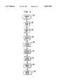
- FIG. 5is a high level flow chart depicting one sequence of possible steps for storing information in and transmitting that information to the packet receiver from the premises recording unit.
- FIG. 6is a high level block diagram of the transmitter and receiver of the present invention which can be used without a premises recording unit.
- FIG. 1there is illustrated generally at 10 a system of the present invention for recording and displaying information received over a telephone network and transmitting that information to a packet receiver, indicated generally at 11, positioned at the door entrance to a home or office, shown environmentally in FIG. 1.
- a packet receiverindicated generally at 11
- a busy business traveler or residential homeowner entering the premisescan quickly glance at the display 11a, which can also be scrolled to look at the most pertinent details and messages left on a premises recording unit, indicated generally at 12.
- a premises recording unitis not always desirable, and information, such as temperature or caller ID received from the telephone network can be transmitted to the packet receiver 11 without the necessity of a recording unit.
- the transmittershown in FIG. 1 and indicated generally at 13, is not a recording unit, but connects directly to the telephone system. It can be placed on a desk as illustrated in FIG. 1.
- the premises recording unit 12includes a housing 12a enclosing the unit 12, which is connected to an information source such as a telephone network 14 which includes a local office 15, such as by standard telephone connectors.
- the unit 12also connects to premises phone 14a (FIG. 2).
- premises phone 14aFIG. 2
- FIG. 2shows an outside telephone network, one skilled in the art will realize that the network could be a local or wide area network of various types, including a telephone network.
- the premises recording unit 12is connected to a first communication channel 16, which could be twisted wire pair or other communication system known to those skilled in the art.
- a premises recording systemis mounted within the housing for recording information, telephone messages and prompts are saved along the first communication channel 16.
- the premises recording system 18further includes a microprocessor 20, and a memory 22, which stores information, telephone messages and prompts received along the first communication channel 16.
- the microprocessor 20 and memory 22are connected along a digital bus 24.
- the memorycan be RAM 22a or other known memory devices.
- the premises recording system 18also includes a caller identification circuit 25 for identifying a caller such as by the caller ID codes now a part of many network calls.
- the caller identification circuit 25is connected to the first communication channel 16, also called the incoming line.
- An analog-to-digital convertor 26is connected along the digital bus and first communication channel 16 to receive analog signals transmitted along that incoming line. The analog signals are converted to digital signals, which then can be stored in memory 22 and processed by the microprocessor 20.
- a dual tone multi-frequency detection circuit 30is also a part of the premises recording system 18 as well as voice recognition circuitry 32 for responding to voice commands. Both circuits 30, 32 connect to the microprocessor 20 and the first communication channel 16.
- a video memory circuit 36 and video driver circuit 38are connected to the digital bus.
- a standard video interface connector 40is mounted on the housing and connected to circuits 36, 38 to interface with a video display such as the television set 42 for displaying stored information, telephone messages and prompts (FIG. 1).
- the digital bus 24also includes an expansion bus 44.
- Cartridge slots 46are formed in the housing 12 and can receive cartridges 48 for interconnecting with the expansion bus 44 and expanding the various functions of the premises recording unit 10.
- one cartridgecould include a packet radio transmitter for generating packet signals to the packet receiver 11.
- the premises recording unit 10includes an infrared receiver 50 operatively connected to the microprocessor 20 and the digital bus 24 for receiving infrared control signals 52 generated from a source such as a premises control unit 54 (FIG. 2).
- the premises recording system 18is responsive to infrared control signals 52 so that stored information, telephone messages and prompts can be retrieved and displayed on the video display such as the television set 42.
- the receiver 50could be a radio receiver which receives radio control signals.
- the premises control unit 54is an infrared generator that generates a sequence of infrared control signals along a second communication channel defined in the air space of a premises to the infrared receiver 50. These signals could be bounced off a light colored ceiling, such as found in many homes.
- the control unit 54generates radio control signals.
- the premises control unit 54is a hand held remote control that can include a key pad 58 for inputting desired functions that correspond to a desired sequence of operations by the premises recording unit (FIG. 2).
- a standard, universal remotemay also be used with some functions. The use of a universal remote, however, will depend on the desired functions required in the premises recording unit.
- a serial port 56can be also connected to the microprocessor so that an external modem or other serial device can be connected thereto (FIG. 3).
- the serial port 58can accommodate a separate controller, modem, or other device.
- a modem cartridge 62can be inserted within the cartridge slot 46 and operatively connected to the digital bus 24 via the expansion bus 44.
- a displayshown by dotted lines at 63, can be mounted directly on the premises recording unit.
- a premises phone(not shown) can be connected to the premises recording unit through a standard phone connection 64.
- a cable set top box 70is operatively connected to an incoming cable line 72 from a cable company 74 and the premises recording unit 10.
- the cableloops through the unit 10 to the television 42.
- the premises recording system 18also includes a microprocessor 20, memory 22, and expandable bus 24, additional hardware or programming software can be added so that the unit 10 can receive, store and process information received from the cable. This can be advantageous if telephone systems and cable systems merge into one communication system.
- the premises recording system 18may include a ring detection circuit 78 (FIG. 2) which registers the number of rings made by a premises phone. After a predetermined number of unanswered rings, the call is answered by the unit 10. The call is then routed to the unit 10, which can play a prerecorded message. The caller then can follow announcements and prompts to retrieve messages or leave other messages, or download information such as digital data. Also, any recorded messages could be played through the television 42.
- a ring detection circuit 78FIG. 2 which registers the number of rings made by a premises phone. After a predetermined number of unanswered rings, the call is answered by the unit 10. The call is then routed to the unit 10, which can play a prerecorded message. The caller then can follow announcements and prompts to retrieve messages or leave other messages, or download information such as digital data. Also, any recorded messages could be played through the television 42.
- the unit 10can be controlled by a selected DTMF sequence from a network phone, such as an outside caller.
- the unit 10can be programmed to give prerecorded answers.
- An additional memory system(not shown) could provide prerecorded responses, such as prompts, for instructing the caller of how to respond to retrieve messages in or out of the home.
- the unit 10also can be programmed to give visual prompting to a user by means of the interface with the television.
- the use of cartridgesalso ensures “plug and play” simplicity, making operation and use of the unit 10 simple. No additional wiring is necessary with the present unit.
- Additional RAMcan provide additional "fast” storage for file storage.
- the unit 10can also receive JPEG files which are compressed still images.
- An additional cartridgecan hold JPEG Fax software to generate menus and allow color display on the TV using the internal video RAM.
- JPEG filesreside in FAX/Modem memory, premises control unit memory, or on a disk.
- a modemcan also transfer color images for displaying on the television or other display.
- the remote control keypad 58can be more complicated, and include various other structure and functions, such as a full alphanumeric keypad, scratchpad or trackball (not shown).
- the unit 10can be programmed to conduct banking, or other services so that financial data can be downloaded to the unit 10.
- the premises recording system 18in accordance with the present invention includes a packet radio transmitter 90 for receiving information concerning a call and generating and transmitting a packet of the information to the packet receiver 11.
- the packet radio transmitterindicated generally at 90 can be positioned on a circuit board, indicated by the dotted lines at 91, and operatively connected to the internal bus 24, thus forming an integral part of the bus and premises recording system. Additionally, the packet transmitter can be formed on a cartridge 48 and inserted within a slot 46.
- the packet radio transmitter of the present inventioncan vary in its working frequency.
- the transmitterpreferably works at an operating frequency of about 2.45 GHz. This operating frequency is desirable since it is presently unlicensed, underpopulated and requires only a very small antenna 93 which can be attached directly to the circuit board.
- the packet of informationcontains an address portion 94 and data portion 94a (FIG. 2).
- the address portion 94notes a desired address for which the packet receiver 11 is to receive the data. This could include the packet receiver 11 contained adjacent to the entrance to a door as well as other packet receivers located around the office or residence, such as on the desk.
- the packet receiver 11includes a circuit board 11b and related circuitry, and a receiving antenna 11c for receiving the packet stream and processing the information for the display.
- FIG. 4illustrates the display 11a of a packet receiver 11 and the type of information which can be displayed on a display screen of the packet receiver 11.
- the packet receiver display screen 11acan be an LCD or LED depending on where the packet receiver is located. When the packet receiver is located at the entrance to an office or residence, as shown in FIG. 1, an LED screen would be more desirable since it would light the information. If an LCD screen is used, an internal light can light the LCD display at night.
- Typical information which can be displayed on the displaycan include the name of the caller, the telephone number, and the time of the call as well as information concerning faxes and if there are any audio messages.
- This brief summarywould be adequate to enable the harried traveller or residence owner to input information via a packet receiver keypad 95, which can be transmitted to the premises recording unit to begin display of all messages and audio messages or quickly make calls back as necessary.
- the transmitted messagescan be simple, and can be generated by an infrared or packet radio transmitter and antenna 11d that generates signals to a receiving antenna 93a.
- This generated packet receiver informationcan also include a signal requesting transmission of audio information for broadcast through the speaker 95a (FIG. 4).
- the packet receiver 11can be formed from a plastic housing 96, and be about as large as the palm of a hand. All circuitry is located within the housing 96.
- FIG. 6there is illustrated the transmitter 90 and receiver 11 of the present invention which in one aspect can be stand-alone units for use without the recording function of a premises recording unit.
- a controller 100is positioned on a circuit board 91.
- a serial line 102is connected into the controller 100 and receives information such as from a modem or other source.
- a temperature sensorcan also be connected directly into the controller 100.
- the transmitter 91then transmits temperature readings to the receiver 11 which are then displayed on the LCD 11a.
- caller IDWhen the transmitter 91 is connected to the local exchange carrier 15, caller ID, indicated at block 106, is retrieved.
- the controllerinputs signals directly to a digital to analog (D/A) converter 108 and then to a voltage controlled oscillator (VCO) 110 and then into a switch 112. From the switch the signal is then transmitted to a power amplifier 114 which then amplifies the signal for transmission to the receiver via an antenna 116 positioned on the circuit board 91. Extraneous signals can be dumped via circuit 120.
- D/Adigital to analog
- VCOvoltage controlled oscillator
- the transmitted signalis then sent to the receiver 11 and received by receiver antenna 11c positioned on the circuit board 11b.
- the received signalis then forwarded to a diode detector 130 which rectifies the signal.
- the signalthen is amplified by video amplifier 132 and sent to a controller 134 and displayed on an LCD 11a. It should be understood that the described transmitter 90 and receiver 11 can be part of the premises recording unit or separate subsets and stand-alone units.
- FIG. 5illustrates the various steps of one aspect of the invention. For purposes of understanding the blocks of the flow chart are numbered with numerals starting in the 200 series.
- the ring detection circuit 84detects the number of rings and transmits this information to the microprocessor 32 (block 202).
- a response to the ring detection circuit, the microprocessor 32generates instructions to other components so that the call is answered (block 204).
- a menu is givenis given asking for several prompts (block 206).
- the callercan respond be a selected keypad sequence, such as **T* or any other desired prompts (block 208).
- the outside callercan retrieve messages if a certain password is entered based on instructed prompts. Selected messages recorded in memory then can be retrieved (block 210).
- the network callercan leave a message (block 212).
- Basic informationsuch as the caller identification, the caller and the time of the call is then input into a digital sequence and forms part of the data information for a packet (Block 214).
- the packetthen is transmitted by means of the radio transmitter and the address portion of the packet then dictates where and to what packet receiver (Block 216). If there is a fax message or an audio message that also can be displayed.
Landscapes
- Engineering & Computer Science (AREA)
- Signal Processing (AREA)
- Computer Networks & Wireless Communication (AREA)
- Human Computer Interaction (AREA)
- Telephonic Communication Services (AREA)
- Mobile Radio Communication Systems (AREA)
Abstract
Description
Claims (13)
Priority Applications (5)
| Application Number | Priority Date | Filing Date | Title |
|---|---|---|---|
| US08/369,201US5615252A (en) | 1995-01-05 | 1995-01-05 | System and apparatus for recording and displaying received information at a remote location |
| GB9525594AGB2296841B (en) | 1995-01-05 | 1995-12-14 | System and apparatus for displaying information |
| CA002165491ACA2165491A1 (en) | 1995-01-05 | 1995-12-18 | System and apparatus for recording and displaying received information at a remote location |
| JP7342455AJPH08251306A (en) | 1995-01-05 | 1995-12-28 | Systems and devices for recording and displaying information received at remote locations |
| US08/597,004US5727053A (en) | 1995-01-05 | 1996-02-05 | System and apparatus for recording and displaying received information at a remote location |
Applications Claiming Priority (1)
| Application Number | Priority Date | Filing Date | Title |
|---|---|---|---|
| US08/369,201US5615252A (en) | 1995-01-05 | 1995-01-05 | System and apparatus for recording and displaying received information at a remote location |
Related Child Applications (1)
| Application Number | Title | Priority Date | Filing Date |
|---|---|---|---|
| US08/597,004ContinuationUS5727053A (en) | 1995-01-05 | 1996-02-05 | System and apparatus for recording and displaying received information at a remote location |
Publications (1)
| Publication Number | Publication Date |
|---|---|
| US5615252Atrue US5615252A (en) | 1997-03-25 |
Family
ID=23454509
Family Applications (2)
| Application Number | Title | Priority Date | Filing Date |
|---|---|---|---|
| US08/369,201Expired - Fee RelatedUS5615252A (en) | 1995-01-05 | 1995-01-05 | System and apparatus for recording and displaying received information at a remote location |
| US08/597,004Expired - Fee RelatedUS5727053A (en) | 1995-01-05 | 1996-02-05 | System and apparatus for recording and displaying received information at a remote location |
Family Applications After (1)
| Application Number | Title | Priority Date | Filing Date |
|---|---|---|---|
| US08/597,004Expired - Fee RelatedUS5727053A (en) | 1995-01-05 | 1996-02-05 | System and apparatus for recording and displaying received information at a remote location |
Country Status (4)
| Country | Link |
|---|---|
| US (2) | US5615252A (en) |
| JP (1) | JPH08251306A (en) |
| CA (1) | CA2165491A1 (en) |
| GB (1) | GB2296841B (en) |
Cited By (38)
| Publication number | Priority date | Publication date | Assignee | Title |
|---|---|---|---|---|
| US6181928B1 (en)* | 1997-08-21 | 2001-01-30 | Ericsson Inc. | Method and apparatus for event notification for wireless devices |
| US6240164B1 (en)* | 1998-06-05 | 2001-05-29 | David D. Jensen | Method and apparatus for providing call detail records at subscriber premises |
| US20020168055A1 (en)* | 2000-11-21 | 2002-11-14 | Crockett Susanne Marie | Voice enhancing for advance intelligent network services |
| US20030079028A1 (en)* | 2001-10-24 | 2003-04-24 | Sbc Technology Resources, Inc. | Unified interface for managing DSL services |
| US6631186B1 (en) | 1999-04-09 | 2003-10-07 | Sbc Technology Resources, Inc. | System and method for implementing and accessing call forwarding services |
| US6633635B2 (en) | 1999-12-30 | 2003-10-14 | At&T Corp. | Multiple call waiting in a packetized communication system |
| US6671262B1 (en) | 1999-12-30 | 2003-12-30 | At&T Corp. | Conference server for automatic x-way call port expansion feature |
| US6678265B1 (en) | 1999-12-30 | 2004-01-13 | At&T Corp. | Local number portability database for on-net IP call |
| US6680935B1 (en) | 1999-12-30 | 2004-01-20 | At&T Corp. | Anonymous call rejection |
| US20040022379A1 (en)* | 1997-04-03 | 2004-02-05 | Southwestern Bell Telephone Company | Apparatus and method for facilitating service management of communications services in a communications network |
| US6690675B1 (en) | 1999-12-30 | 2004-02-10 | At&T Corp. | User programmable fail-proof IP hotline/warm-line |
| US6728239B1 (en) | 1999-12-30 | 2004-04-27 | At&T Corp. | Scaleable network server for low cost PBX |
| US20040151294A1 (en)* | 1997-04-03 | 2004-08-05 | Sbc Technology Resources, Inc. | Profile management system including user interface for accessing and maintaining profile data of user subscribed telephony services |
| US6775267B1 (en) | 1999-12-30 | 2004-08-10 | At&T Corp | Method for billing IP broadband subscribers |
| US6775273B1 (en) | 1999-12-30 | 2004-08-10 | At&T Corp. | Simplified IP service control |
| US6816469B1 (en) | 1999-12-30 | 2004-11-09 | At&T Corp. | IP conference call waiting |
| US6826173B1 (en) | 1999-12-30 | 2004-11-30 | At&T Corp. | Enhanced subscriber IP alerting |
| US6889321B1 (en) | 1999-12-30 | 2005-05-03 | At&T Corp. | Protected IP telephony calls using encryption |
| US6891940B1 (en) | 2000-07-19 | 2005-05-10 | Sbc Technology Resources, Inc. | System and method for providing remote access to telecommunications services |
| US6917610B1 (en) | 1999-12-30 | 2005-07-12 | At&T Corp. | Activity log for improved call efficiency |
| US6937713B1 (en) | 1999-12-30 | 2005-08-30 | At&T Corp. | IP call forward profile |
| US6954524B2 (en) | 2002-06-07 | 2005-10-11 | Sbc Properties, L.P. | System and method for implementing and accessing call forwarding services |
| US20060056388A1 (en)* | 2004-08-24 | 2006-03-16 | Comcast Cable Holdings, Llc | Method and system for locating a voice over internet protocol (VoIP) device connected to a network |
| US7075918B1 (en) | 1999-12-30 | 2006-07-11 | At&T Corp. | BRG with PBX capabilities |
| US7120139B1 (en) | 1999-12-30 | 2006-10-10 | At&T Corp. | Broadband cable telephony network architecture IP ITN network architecture reference model |
| US7142846B1 (en) | 1994-01-05 | 2006-11-28 | Henderson Daniel A | Method and apparatus for improved paging receiver and system |
| US7155001B2 (en) | 2001-10-24 | 2006-12-26 | Sbc Properties, L.P. | System and method for restricting and monitoring telephone calls |
| US7180889B1 (en) | 1999-12-30 | 2007-02-20 | At&T Corp. | Personal control of address assignment and greeting options for multiple BRG ports |
| US7206398B2 (en) | 1998-07-09 | 2007-04-17 | Sbc Technology Resources, Inc. | System and method for forwarding call from disconnected telephone number to new telephone number |
| US7251318B1 (en) | 1994-01-05 | 2007-07-31 | Intellect Wireless Inc. | Method and apparatus for improved personal communication devices and systems |
| US7257210B1 (en) | 1994-01-05 | 2007-08-14 | Intellect Wireless Inc. | Picture phone with caller id |
| US20080089503A1 (en)* | 2002-04-30 | 2008-04-17 | At&T Knowledge Ventures, L.P. | Voice enhancing for advance intelligent network services |
| US20080103529A1 (en)* | 2006-10-26 | 2008-05-01 | Old Dominion University | Apparatus and methods for performing cellular electro-manipulations |
| US7502457B2 (en) | 2002-02-28 | 2009-03-10 | At&T Intellectual Property I, L.P. | Outbound call rules routing |
| US9286294B2 (en) | 1992-12-09 | 2016-03-15 | Comcast Ip Holdings I, Llc | Video and digital multimedia aggregator content suggestion engine |
| US9813641B2 (en) | 2000-06-19 | 2017-11-07 | Comcast Ip Holdings I, Llc | Method and apparatus for targeting of interactive virtual objects |
| US10140433B2 (en) | 2001-08-03 | 2018-11-27 | Comcast Ip Holdings I, Llc | Video and digital multimedia aggregator |
| US10349096B2 (en) | 2001-08-03 | 2019-07-09 | Comcast Ip Holdings I, Llc | Video and digital multimedia aggregator content coding and formatting |
Families Citing this family (12)
| Publication number | Priority date | Publication date | Assignee | Title |
|---|---|---|---|---|
| US6133853A (en) | 1998-07-30 | 2000-10-17 | American Calcar, Inc. | Personal communication and positioning system |
| US6148261A (en) | 1997-06-20 | 2000-11-14 | American Calcar, Inc. | Personal communication system to send and receive voice data positioning information |
| WO2000024131A1 (en) | 1998-10-21 | 2000-04-27 | American Calcar, Inc. | Positional camera and gps data interchange device |
| US6298128B1 (en) | 1999-03-11 | 2001-10-02 | Thomson Licensing S.A. | Unified directory for caller ID and electronic mail addresses |
| JP2001069475A (en)* | 1999-08-27 | 2001-03-16 | Pioneer Electronic Corp | Terminal for cable television |
| KR100845568B1 (en) | 1999-10-19 | 2008-07-10 | 아메리칸 캘카어 인코포레이티드 | Technique for effective navigation based on user preferences |
| US7475057B1 (en) | 1999-10-27 | 2009-01-06 | American Calcar, Inc. | System and method for user navigation |
| CA2405060A1 (en) | 2000-04-11 | 2001-10-18 | American Calcar, Inc. | Gps publication application server |
| US7020488B1 (en) | 2000-07-19 | 2006-03-28 | Embedded Systems Products Inc. | Communications unit, system and methods for providing multiple access to a wireless transceiver |
| AU2001278953A1 (en)* | 2000-07-28 | 2002-02-13 | American Calcar, Inc. | Technique for effective organization and communication of information |
| US7162228B2 (en)* | 2002-04-03 | 2007-01-09 | Embedded Systems Products Inc. | Apparatus, method, media and signals for controlling a wireless communication appliance |
| US8031069B2 (en) | 2008-01-14 | 2011-10-04 | Oded Yair Cohn | Electronic security seal and system |
Citations (12)
| Publication number | Priority date | Publication date | Assignee | Title |
|---|---|---|---|---|
| US4172969A (en)* | 1975-12-03 | 1979-10-30 | Boris Haskell | Real time absentee telephone and radiant wave signaling system |
| US4197526A (en)* | 1975-12-03 | 1980-04-08 | Boris Haskell | Miniature pager receiver with digital display and memory |
| US4821308A (en)* | 1985-03-19 | 1989-04-11 | Hashimoto Corporation | Telephone answering system with paging function |
| US4885766A (en)* | 1986-01-31 | 1989-12-05 | Sharp Kabushiki Kaisha | Remote control device using a telephone line |
| US4961216A (en)* | 1988-12-30 | 1990-10-02 | Baehr G Geoffrey | Telephone answering and paging system |
| US5014125A (en)* | 1989-05-05 | 1991-05-07 | Cableshare, Inc. | Television system for the interactive distribution of selectable video presentations |
| US5027426A (en)* | 1989-07-07 | 1991-06-25 | Chiocca Jr Joseph J | Signal coupling device and system |
| US5228073A (en)* | 1991-07-22 | 1993-07-13 | Smith Frederick D | Call identification display system |
| US5247347A (en)* | 1991-09-27 | 1993-09-21 | Bell Atlantic Network Services, Inc. | Pstn architecture for video-on-demand services |
| US5329308A (en)* | 1992-07-29 | 1994-07-12 | At&T Bell Laboratories | Bidirectional video telephony between cable television and switched telephone systems |
| US5343516A (en)* | 1989-09-29 | 1994-08-30 | Digital Systems Group, Inc. | Computer telecommunications signalling interface |
| US5388150A (en)* | 1992-07-28 | 1995-02-07 | Schneyer; Robin | Automatic incoming telephone call identification and disposition system |
- 1995
- 1995-01-05USUS08/369,201patent/US5615252A/ennot_activeExpired - Fee Related
- 1995-12-14GBGB9525594Apatent/GB2296841B/ennot_activeExpired - Fee Related
- 1995-12-18CACA002165491Apatent/CA2165491A1/ennot_activeAbandoned
- 1995-12-28JPJP7342455Apatent/JPH08251306A/ennot_activeWithdrawn
- 1996
- 1996-02-05USUS08/597,004patent/US5727053A/ennot_activeExpired - Fee Related
Patent Citations (12)
| Publication number | Priority date | Publication date | Assignee | Title |
|---|---|---|---|---|
| US4172969A (en)* | 1975-12-03 | 1979-10-30 | Boris Haskell | Real time absentee telephone and radiant wave signaling system |
| US4197526A (en)* | 1975-12-03 | 1980-04-08 | Boris Haskell | Miniature pager receiver with digital display and memory |
| US4821308A (en)* | 1985-03-19 | 1989-04-11 | Hashimoto Corporation | Telephone answering system with paging function |
| US4885766A (en)* | 1986-01-31 | 1989-12-05 | Sharp Kabushiki Kaisha | Remote control device using a telephone line |
| US4961216A (en)* | 1988-12-30 | 1990-10-02 | Baehr G Geoffrey | Telephone answering and paging system |
| US5014125A (en)* | 1989-05-05 | 1991-05-07 | Cableshare, Inc. | Television system for the interactive distribution of selectable video presentations |
| US5027426A (en)* | 1989-07-07 | 1991-06-25 | Chiocca Jr Joseph J | Signal coupling device and system |
| US5343516A (en)* | 1989-09-29 | 1994-08-30 | Digital Systems Group, Inc. | Computer telecommunications signalling interface |
| US5228073A (en)* | 1991-07-22 | 1993-07-13 | Smith Frederick D | Call identification display system |
| US5247347A (en)* | 1991-09-27 | 1993-09-21 | Bell Atlantic Network Services, Inc. | Pstn architecture for video-on-demand services |
| US5388150A (en)* | 1992-07-28 | 1995-02-07 | Schneyer; Robin | Automatic incoming telephone call identification and disposition system |
| US5329308A (en)* | 1992-07-29 | 1994-07-12 | At&T Bell Laboratories | Bidirectional video telephony between cable television and switched telephone systems |
Non-Patent Citations (1)
| Title |
|---|
| British Search Report No. GB 9525594.9.* |
Cited By (96)
| Publication number | Priority date | Publication date | Assignee | Title |
|---|---|---|---|---|
| US9286294B2 (en) | 1992-12-09 | 2016-03-15 | Comcast Ip Holdings I, Llc | Video and digital multimedia aggregator content suggestion engine |
| US7266186B1 (en) | 1994-01-05 | 2007-09-04 | Intellect Wireless Inc. | Method and apparatus for improved paging receiver and system |
| US7254223B1 (en) | 1994-01-05 | 2007-08-07 | Intellect Wireless Inc. | Method and apparatus for improved personal communication devices and systems |
| US7142846B1 (en) | 1994-01-05 | 2006-11-28 | Henderson Daniel A | Method and apparatus for improved paging receiver and system |
| US7251318B1 (en) | 1994-01-05 | 2007-07-31 | Intellect Wireless Inc. | Method and apparatus for improved personal communication devices and systems |
| US7310416B1 (en) | 1994-01-05 | 2007-12-18 | Intellect Wireless Inc. | Method and apparatus for improved personal communication devices and systems |
| US7257210B1 (en) | 1994-01-05 | 2007-08-14 | Intellect Wireless Inc. | Picture phone with caller id |
| US7286658B1 (en) | 1994-01-05 | 2007-10-23 | Intellect Wireless Inc. | Method and apparatus for improved personal communication devices and systems |
| US7305076B1 (en) | 1994-01-05 | 2007-12-04 | Intellect Wireless Inc. | Method and apparatus for improved paging receiver and system |
| US7308088B1 (en) | 1994-01-05 | 2007-12-11 | Intellect Wireless, Inc. | Method and apparatus for improved personal communication devices and systems |
| US7349532B2 (en) | 1994-01-05 | 2008-03-25 | Intellect Wireless Inc. | Picture and video message center system |
| US20070293204A1 (en)* | 1994-01-05 | 2007-12-20 | Henderson Daniel A | Method and apparatus for improved paging receiver and system |
| US7426264B1 (en) | 1994-01-05 | 2008-09-16 | Henderson Daniel A | Method and apparatus for improved personal communication devices and systems |
| US7454000B1 (en) | 1994-01-05 | 2008-11-18 | Intellect Wireless, Inc. | Method and apparatus for improved personal communication devices and systems |
| US7103165B2 (en) | 1997-04-03 | 2006-09-05 | Sbc Technology Resources, Inc. | Profile management system including user interface for accessing and maintaining profile data of user subscribed telephony services |
| US7907714B2 (en) | 1997-04-03 | 2011-03-15 | At&T Labs, Inc. | Profile management system including user interface for accessing and maintaining profile data of user subscribed telephony services |
| US20110142213A1 (en)* | 1997-04-03 | 2011-06-16 | At&T Labs, Inc. | Profile management system including user interface for accessing and maintaining profile data of user subscribed telephony services |
| US7167550B2 (en) | 1997-04-03 | 2007-01-23 | Southwestern Bell Telephone Company | Apparatus and method for facilitating service management of communications services in a communications network |
| US20040022379A1 (en)* | 1997-04-03 | 2004-02-05 | Southwestern Bell Telephone Company | Apparatus and method for facilitating service management of communications services in a communications network |
| US8705718B2 (en) | 1997-04-03 | 2014-04-22 | At&T Intellectual Property I, L.P. | Profile management system including user interface for accessing and maintaining profile data of user subscribed telephony services |
| US8139742B2 (en) | 1997-04-03 | 2012-03-20 | At&T Intellectual Property I, L.P. | Apparatus and method for facilitating service management of communications services in a communications network |
| US20070121850A1 (en)* | 1997-04-03 | 2007-05-31 | Southwestern Bell Telephone Company | Apparatus and method for facilitating service management of communications services in a communications network |
| US8494138B2 (en) | 1997-04-03 | 2013-07-23 | At&T Intellectual Property I, L.P. | Profile management system including user interface for accessing and maintaining profile data of user subscribed telephony services |
| US20040151294A1 (en)* | 1997-04-03 | 2004-08-05 | Sbc Technology Resources, Inc. | Profile management system including user interface for accessing and maintaining profile data of user subscribed telephony services |
| US20070047714A1 (en)* | 1997-04-03 | 2007-03-01 | Sbc Technology Resources, Inc. | Profile management system including user interface for accessing and maintaining profile data of user subscribed telephony services |
| US9369574B2 (en) | 1997-04-03 | 2016-06-14 | At&T Intellectual Property I, L.P. | Profile management system including user interface for accessing and maintaining profile data of user subscribed telephony services |
| US6181928B1 (en)* | 1997-08-21 | 2001-01-30 | Ericsson Inc. | Method and apparatus for event notification for wireless devices |
| US6240164B1 (en)* | 1998-06-05 | 2001-05-29 | David D. Jensen | Method and apparatus for providing call detail records at subscriber premises |
| US6373934B2 (en)* | 1998-06-05 | 2002-04-16 | David D. Jensen | Method and apparatus for providing call detail records at subscriber premises |
| US7206398B2 (en) | 1998-07-09 | 2007-04-17 | Sbc Technology Resources, Inc. | System and method for forwarding call from disconnected telephone number to new telephone number |
| US6631186B1 (en) | 1999-04-09 | 2003-10-07 | Sbc Technology Resources, Inc. | System and method for implementing and accessing call forwarding services |
| US7242754B2 (en) | 1999-04-09 | 2007-07-10 | At&T Labs, Inc. | System and method for implementing and accessing call forwarding services |
| US20070217584A1 (en)* | 1999-04-09 | 2007-09-20 | At&T Labs, Inc. | System and method for implementing and accessing call forwarding services |
| US20040005045A1 (en)* | 1999-04-09 | 2004-01-08 | Sbc Technology Resources, Inc., Austin, Texas | System and method for implementing and accessing call forwarding services |
| US8054963B2 (en) | 1999-12-30 | 2011-11-08 | Shoretel, Inc. | System with call forward profile |
| US8514846B2 (en) | 1999-12-30 | 2013-08-20 | Shoretel, Inc. | Responding to IP call with a prompt to select an extension and routing packets to IP phone at selected extension |
| US6775267B1 (en) | 1999-12-30 | 2004-08-10 | At&T Corp | Method for billing IP broadband subscribers |
| US9300699B2 (en) | 1999-12-30 | 2016-03-29 | Shoretel, Inc. | System with call forward profile |
| US7120139B1 (en) | 1999-12-30 | 2006-10-10 | At&T Corp. | Broadband cable telephony network architecture IP ITN network architecture reference model |
| US9167097B2 (en) | 1999-12-30 | 2015-10-20 | Shoretel, Inc. | Responding to a call with a prompt and routing the call to a phone selected in response to the prompt |
| US7075918B1 (en) | 1999-12-30 | 2006-07-11 | At&T Corp. | BRG with PBX capabilities |
| US8711735B2 (en) | 1999-12-30 | 2014-04-29 | At&T Intellectual Property, Ii, L.P. | Personal IP toll-free number |
| US6633635B2 (en) | 1999-12-30 | 2003-10-14 | At&T Corp. | Multiple call waiting in a packetized communication system |
| US8666053B2 (en) | 1999-12-30 | 2014-03-04 | Shoretel, Inc. | System with call forward profile |
| US6937713B1 (en) | 1999-12-30 | 2005-08-30 | At&T Corp. | IP call forward profile |
| US6917610B1 (en) | 1999-12-30 | 2005-07-12 | At&T Corp. | Activity log for improved call efficiency |
| US6775273B1 (en) | 1999-12-30 | 2004-08-10 | At&T Corp. | Simplified IP service control |
| US20090154681A1 (en)* | 1999-12-30 | 2009-06-18 | At&T Intellectual Property Ii, L.P. | System with Call Forward Profile |
| US6889321B1 (en) | 1999-12-30 | 2005-05-03 | At&T Corp. | Protected IP telephony calls using encryption |
| US6826173B1 (en) | 1999-12-30 | 2004-11-30 | At&T Corp. | Enhanced subscriber IP alerting |
| US7180889B1 (en) | 1999-12-30 | 2007-02-20 | At&T Corp. | Personal control of address assignment and greeting options for multiple BRG ports |
| US6671262B1 (en) | 1999-12-30 | 2003-12-30 | At&T Corp. | Conference server for automatic x-way call port expansion feature |
| US6678265B1 (en) | 1999-12-30 | 2004-01-13 | At&T Corp. | Local number portability database for on-net IP call |
| US6816469B1 (en) | 1999-12-30 | 2004-11-09 | At&T Corp. | IP conference call waiting |
| US6680935B1 (en) | 1999-12-30 | 2004-01-20 | At&T Corp. | Anonymous call rejection |
| US6690675B1 (en) | 1999-12-30 | 2004-02-10 | At&T Corp. | User programmable fail-proof IP hotline/warm-line |
| US6728239B1 (en) | 1999-12-30 | 2004-04-27 | At&T Corp. | Scaleable network server for low cost PBX |
| US20090310600A1 (en)* | 1999-12-30 | 2009-12-17 | At&T Intellectual Property Ii, L.P. | Personal Control of Address Assignments & Greeting Options for Multiple BRG Ports |
| US9813641B2 (en) | 2000-06-19 | 2017-11-07 | Comcast Ip Holdings I, Llc | Method and apparatus for targeting of interactive virtual objects |
| US6891940B1 (en) | 2000-07-19 | 2005-05-10 | Sbc Technology Resources, Inc. | System and method for providing remote access to telecommunications services |
| US7593396B2 (en) | 2000-07-19 | 2009-09-22 | At&T Labs, Inc. | System and method for providing remote access to telecommunications services |
| US7317787B2 (en) | 2000-11-21 | 2008-01-08 | At&T Knowledge Ventures, L.P. | Voice enhancing for advance intelligent network services |
| US20020168055A1 (en)* | 2000-11-21 | 2002-11-14 | Crockett Susanne Marie | Voice enhancing for advance intelligent network services |
| US10349096B2 (en) | 2001-08-03 | 2019-07-09 | Comcast Ip Holdings I, Llc | Video and digital multimedia aggregator content coding and formatting |
| US10140433B2 (en) | 2001-08-03 | 2018-11-27 | Comcast Ip Holdings I, Llc | Video and digital multimedia aggregator |
| US8155293B2 (en) | 2001-10-24 | 2012-04-10 | At&T Intellectual Property I, L.P. | System and method for restricting and monitoring telephone calls |
| US20080279359A1 (en)* | 2001-10-24 | 2008-11-13 | At&T Intellectual Property I,L.P. | System and method for restricting and monitoring telephone calls |
| US7418089B2 (en) | 2001-10-24 | 2008-08-26 | At&T Intellectual Property I, L.P. | System and method for restricting and monitoring telephone calls |
| US20030079028A1 (en)* | 2001-10-24 | 2003-04-24 | Sbc Technology Resources, Inc. | Unified interface for managing DSL services |
| US7155001B2 (en) | 2001-10-24 | 2006-12-26 | Sbc Properties, L.P. | System and method for restricting and monitoring telephone calls |
| US7337220B2 (en) | 2001-10-24 | 2008-02-26 | At&T Labs, Inc. | Unified interface for managing DSL services |
| US7502457B2 (en) | 2002-02-28 | 2009-03-10 | At&T Intellectual Property I, L.P. | Outbound call rules routing |
| US7957509B2 (en) | 2002-04-30 | 2011-06-07 | At&T Intellectual Property I, L.P. | Voice enhancing for advance intelligent network services |
| US20080089503A1 (en)* | 2002-04-30 | 2008-04-17 | At&T Knowledge Ventures, L.P. | Voice enhancing for advance intelligent network services |
| US8059808B2 (en) | 2002-06-07 | 2011-11-15 | At&T Intellectual Property I, L.P. | System and method for implementing and accessing call forwarding services |
| US7346155B2 (en) | 2002-06-07 | 2008-03-18 | At&T Knowledge Ventures, L.P. | System and method for implementing and accessing call forwarding services |
| US20070286391A1 (en)* | 2002-06-07 | 2007-12-13 | At&T Knowledge Ventures, L.P. | System and method for implementing and accessing call forwarding services |
| US6954524B2 (en) | 2002-06-07 | 2005-10-11 | Sbc Properties, L.P. | System and method for implementing and accessing call forwarding services |
| US20060203986A1 (en)* | 2002-06-07 | 2006-09-14 | Sbc Properties L.P. | System and method for implementing and accessing call forwarding services |
| US7076045B2 (en) | 2002-06-07 | 2006-07-11 | Sbc Properties, L.P. | System and method for implementing and accessing call forward services |
| US20080170680A1 (en)* | 2002-06-07 | 2008-07-17 | At & T Knowledge Ventures, L.P. | System and method for implementing and accessing call forwarding services |
| US7227940B2 (en) | 2002-06-07 | 2007-06-05 | At&T Knowledge Ventures, B.P. | System and method for implementing and accessing call forwarding services |
| US7778403B2 (en) | 2002-06-07 | 2010-08-17 | At&T Intellectual Property I, L.P. | System and method for implementing and accessing call forwarding services |
| US20060056388A1 (en)* | 2004-08-24 | 2006-03-16 | Comcast Cable Holdings, Llc | Method and system for locating a voice over internet protocol (VoIP) device connected to a network |
| US9055550B1 (en) | 2004-08-24 | 2015-06-09 | Comcast Cable Holdings, Llc | Locating a voice over packet (VoP) device connected to a network |
| US9049132B1 (en) | 2004-08-24 | 2015-06-02 | Comcast Cable Holdings, Llc | Locating a voice over packet (VoP) device connected to a network |
| US9036626B2 (en) | 2004-08-24 | 2015-05-19 | Comcast Cable Holdings, Llc | Method and system for locating a voice over internet protocol (VOIP) device connected to a network |
| US8724522B2 (en) | 2004-08-24 | 2014-05-13 | Comcast Cable Holdings, Llc | Method and system for locating a voice over internet protocol (VoIP) device connected to a network |
| US9648644B2 (en) | 2004-08-24 | 2017-05-09 | Comcast Cable Communications, Llc | Determining a location of a device for calling via an access point |
| US10070466B2 (en) | 2004-08-24 | 2018-09-04 | Comcast Cable Communications, Llc | Determining a location of a device for calling via an access point |
| US20110116420A1 (en)* | 2004-08-24 | 2011-05-19 | Comcast Cable Communications, Llc | Method and System for Locating a Voice over Internet Protocol (VOIP) Device Connected to a Network |
| US7940746B2 (en) | 2004-08-24 | 2011-05-10 | Comcast Cable Holdings, Llc | Method and system for locating a voice over internet protocol (VoIP) device connected to a network |
| US10517140B2 (en) | 2004-08-24 | 2019-12-24 | Comcast Cable Communications, Llc | Determining a location of a device for calling via an access point |
| US11252779B2 (en) | 2004-08-24 | 2022-02-15 | Comcast Cable Communications, Llc | Physical location management for voice over packet communication |
| US11956852B2 (en) | 2004-08-24 | 2024-04-09 | Comcast Cable Communications, Llc | Physical location management for voice over packet communication |
| US20080103529A1 (en)* | 2006-10-26 | 2008-05-01 | Old Dominion University | Apparatus and methods for performing cellular electro-manipulations |
Also Published As
| Publication number | Publication date |
|---|---|
| US5727053A (en) | 1998-03-10 |
| GB9525594D0 (en) | 1996-02-14 |
| GB2296841B (en) | 1997-04-30 |
| JPH08251306A (en) | 1996-09-27 |
| CA2165491A1 (en) | 1996-07-06 |
| GB2296841A (en) | 1996-07-10 |
Similar Documents
| Publication | Publication Date | Title |
|---|---|---|
| US5615252A (en) | System and apparatus for recording and displaying received information at a remote location | |
| US5606603A (en) | System and apparatus for recording and displaying received information at a remote location using premises recording unit | |
| US6021324A (en) | System and apparatus for controlling an appliance situated within a premises using premises recording unit | |
| US5390236A (en) | Telephone answering device linking displayed data with recorded audio message | |
| US5566231A (en) | Apparatus and system for recording and accessing information received over a telephone network | |
| US5283818A (en) | Telephone answering device linking displayed data with recorded audio message | |
| US6919918B2 (en) | Electronic digital door opener | |
| KR100689485B1 (en) | Background music providing system and method, and portable terminal | |
| US5566232A (en) | System and apparatus for recording and accessing information received over a phone network using a premises phone for control | |
| US20030086547A1 (en) | Telephonic terminal system | |
| US6108411A (en) | Communication device | |
| JPH10510967A (en) | Interactive multimedia device with caller identification decoding function | |
| JPH1093724A (en) | Telephone equipment | |
| JP2590073B2 (en) | Captain terminal device | |
| JPH0851492A (en) | Still image transmission system using analog telephone line network | |
| JPH0352482A (en) | Image/audio transmitter/receiver | |
| EP0739124A2 (en) | A translator device for receiving data from a telephone and displaying it on a television set | |
| CA2429739C (en) | Telephone answering device linking displayed data with recorded audio message | |
| JP3861767B2 (en) | Information processing system and communication device constituting them | |
| JPH10150487A (en) | Database system | |
| KR20000039516A (en) | Computer providing function of personal information using telephone located at remote place and method therefor | |
| FR2730593A1 (en) | METHOD FOR TRANSMITTING AND RECEIVING ALPHANUMERIC DATA THROUGH THE TELEPHONE NETWORK FOR A USE ASSOCIATED WITH THAT OF VOICE COMPUTER SERVICES | |
| JPH07322233A (en) | Two-way video communication method and its implementation system | |
| JPS62154174A (en) | information terminal equipment |
Legal Events
| Date | Code | Title | Description |
|---|---|---|---|
| AS | Assignment | Owner name:AT & T CORPORATION, NEW JERSEY Free format text:ASSIGNMENT OF ASSIGNORS INTEREST;ASSIGNORS:SIZER, THEODORE II;WRIGHT, GREGORY ALAN;REEL/FRAME:007767/0283 Effective date:19951206 | |
| AS | Assignment | Owner name:LUCENT TECHNOLOGIES INC., NEW JERSEY Free format text:ASSIGNMENT OF ASSIGNORS INTEREST;ASSIGNOR:AT&T CORP.;REEL/FRAME:008196/0181 Effective date:19960329 | |
| FEPP | Fee payment procedure | Free format text:PAYOR NUMBER ASSIGNED (ORIGINAL EVENT CODE: ASPN); ENTITY STATUS OF PATENT OWNER: LARGE ENTITY | |
| FPAY | Fee payment | Year of fee payment:4 | |
| AS | Assignment | Owner name:THE CHASE MANHATTAN BANK, AS COLLATERAL AGENT, TEX Free format text:CONDITIONAL ASSIGNMENT OF AND SECURITY INTEREST IN PATENT RIGHTS;ASSIGNOR:LUCENT TECHNOLOGIES INC. (DE CORPORATION);REEL/FRAME:011722/0048 Effective date:20010222 | |
| REMI | Maintenance fee reminder mailed | ||
| LAPS | Lapse for failure to pay maintenance fees | ||
| STCH | Information on status: patent discontinuation | Free format text:PATENT EXPIRED DUE TO NONPAYMENT OF MAINTENANCE FEES UNDER 37 CFR 1.362 | |
| FP | Lapsed due to failure to pay maintenance fee | Effective date:20050325 | |
| AS | Assignment | Owner name:LUCENT TECHNOLOGIES INC., NEW JERSEY Free format text:TERMINATION AND RELEASE OF SECURITY INTEREST IN PATENT RIGHTS;ASSIGNOR:JPMORGAN CHASE BANK, N.A. (FORMERLY KNOWN AS THE CHASE MANHATTAN BANK), AS ADMINISTRATIVE AGENT;REEL/FRAME:018584/0446 Effective date:20061130 |