US5614885A - Electrical control system for vehicle options - Google Patents
Electrical control system for vehicle optionsDownload PDFInfo
- Publication number
- US5614885A US5614885AUS07/567,390US56739090AUS5614885AUS 5614885 AUS5614885 AUS 5614885AUS 56739090 AUS56739090 AUS 56739090AUS 5614885 AUS5614885 AUS 5614885A
- Authority
- US
- United States
- Prior art keywords
- block
- microcontroller
- control signal
- program
- mirror
- Prior art date
- Legal status (The legal status is an assumption and is not a legal conclusion. Google has not performed a legal analysis and makes no representation as to the accuracy of the status listed.)
- Expired - Lifetime
Links
Images


Classifications
- G—PHYSICS
- G07—CHECKING-DEVICES
- G07C—TIME OR ATTENDANCE REGISTERS; REGISTERING OR INDICATING THE WORKING OF MACHINES; GENERATING RANDOM NUMBERS; VOTING OR LOTTERY APPARATUS; ARRANGEMENTS, SYSTEMS OR APPARATUS FOR CHECKING NOT PROVIDED FOR ELSEWHERE
- G07C9/00—Individual registration on entry or exit
- G07C9/00174—Electronically operated locks; Circuits therefor; Nonmechanical keys therefor, e.g. passive or active electrical keys or other data carriers without mechanical keys
- G07C9/00817—Electronically operated locks; Circuits therefor; Nonmechanical keys therefor, e.g. passive or active electrical keys or other data carriers without mechanical keys where the code of the lock can be programmed
- B—PERFORMING OPERATIONS; TRANSPORTING
- B60—VEHICLES IN GENERAL
- B60R—VEHICLES, VEHICLE FITTINGS, OR VEHICLE PARTS, NOT OTHERWISE PROVIDED FOR
- B60R1/00—Optical viewing arrangements; Real-time viewing arrangements for drivers or passengers using optical image capturing systems, e.g. cameras or video systems specially adapted for use in or on vehicles
- B60R1/02—Rear-view mirror arrangements
- B60R1/04—Rear-view mirror arrangements mounted inside vehicle
- B—PERFORMING OPERATIONS; TRANSPORTING
- B60—VEHICLES IN GENERAL
- B60R—VEHICLES, VEHICLE FITTINGS, OR VEHICLE PARTS, NOT OTHERWISE PROVIDED FOR
- B60R1/00—Optical viewing arrangements; Real-time viewing arrangements for drivers or passengers using optical image capturing systems, e.g. cameras or video systems specially adapted for use in or on vehicles
- B60R1/02—Rear-view mirror arrangements
- B60R1/08—Rear-view mirror arrangements involving special optical features, e.g. avoiding blind spots, e.g. convex mirrors; Side-by-side associations of rear-view and other mirrors
- B60R1/083—Anti-glare mirrors, e.g. "day-night" mirrors
- B60R1/088—Anti-glare mirrors, e.g. "day-night" mirrors using a cell of electrically changeable optical characteristic, e.g. liquid-crystal or electrochromic mirrors
- B—PERFORMING OPERATIONS; TRANSPORTING
- B60—VEHICLES IN GENERAL
- B60R—VEHICLES, VEHICLE FITTINGS, OR VEHICLE PARTS, NOT OTHERWISE PROVIDED FOR
- B60R1/00—Optical viewing arrangements; Real-time viewing arrangements for drivers or passengers using optical image capturing systems, e.g. cameras or video systems specially adapted for use in or on vehicles
- B60R1/12—Mirror assemblies combined with other articles, e.g. clocks
- G—PHYSICS
- G07—CHECKING-DEVICES
- G07C—TIME OR ATTENDANCE REGISTERS; REGISTERING OR INDICATING THE WORKING OF MACHINES; GENERATING RANDOM NUMBERS; VOTING OR LOTTERY APPARATUS; ARRANGEMENTS, SYSTEMS OR APPARATUS FOR CHECKING NOT PROVIDED FOR ELSEWHERE
- G07C9/00—Individual registration on entry or exit
- G07C9/00174—Electronically operated locks; Circuits therefor; Nonmechanical keys therefor, e.g. passive or active electrical keys or other data carriers without mechanical keys
- G07C9/00182—Electronically operated locks; Circuits therefor; Nonmechanical keys therefor, e.g. passive or active electrical keys or other data carriers without mechanical keys operated with unidirectional data transmission between data carrier and locks
- B—PERFORMING OPERATIONS; TRANSPORTING
- B60—VEHICLES IN GENERAL
- B60R—VEHICLES, VEHICLE FITTINGS, OR VEHICLE PARTS, NOT OTHERWISE PROVIDED FOR
- B60R1/00—Optical viewing arrangements; Real-time viewing arrangements for drivers or passengers using optical image capturing systems, e.g. cameras or video systems specially adapted for use in or on vehicles
- B60R1/12—Mirror assemblies combined with other articles, e.g. clocks
- B60R1/1207—Mirror assemblies combined with other articles, e.g. clocks with lamps; with turn indicators
- B—PERFORMING OPERATIONS; TRANSPORTING
- B60—VEHICLES IN GENERAL
- B60R—VEHICLES, VEHICLE FITTINGS, OR VEHICLE PARTS, NOT OTHERWISE PROVIDED FOR
- B60R1/00—Optical viewing arrangements; Real-time viewing arrangements for drivers or passengers using optical image capturing systems, e.g. cameras or video systems specially adapted for use in or on vehicles
- B60R1/12—Mirror assemblies combined with other articles, e.g. clocks
- B60R2001/1215—Mirror assemblies combined with other articles, e.g. clocks with information displays
- B—PERFORMING OPERATIONS; TRANSPORTING
- B60—VEHICLES IN GENERAL
- B60R—VEHICLES, VEHICLE FITTINGS, OR VEHICLE PARTS, NOT OTHERWISE PROVIDED FOR
- B60R1/00—Optical viewing arrangements; Real-time viewing arrangements for drivers or passengers using optical image capturing systems, e.g. cameras or video systems specially adapted for use in or on vehicles
- B60R1/12—Mirror assemblies combined with other articles, e.g. clocks
- B60R2001/1223—Mirror assemblies combined with other articles, e.g. clocks with sensors or transducers
- B—PERFORMING OPERATIONS; TRANSPORTING
- B60—VEHICLES IN GENERAL
- B60R—VEHICLES, VEHICLE FITTINGS, OR VEHICLE PARTS, NOT OTHERWISE PROVIDED FOR
- B60R1/00—Optical viewing arrangements; Real-time viewing arrangements for drivers or passengers using optical image capturing systems, e.g. cameras or video systems specially adapted for use in or on vehicles
- B60R1/12—Mirror assemblies combined with other articles, e.g. clocks
- B60R2001/123—Mirror assemblies combined with other articles, e.g. clocks with thermometers
- B—PERFORMING OPERATIONS; TRANSPORTING
- B60—VEHICLES IN GENERAL
- B60R—VEHICLES, VEHICLE FITTINGS, OR VEHICLE PARTS, NOT OTHERWISE PROVIDED FOR
- B60R1/00—Optical viewing arrangements; Real-time viewing arrangements for drivers or passengers using optical image capturing systems, e.g. cameras or video systems specially adapted for use in or on vehicles
- B60R1/12—Mirror assemblies combined with other articles, e.g. clocks
- B60R2001/1284—Mirror assemblies combined with other articles, e.g. clocks with communication systems other than radio-receivers, e.g. keyless entry systems, navigation systems; with anti-collision systems
- G—PHYSICS
- G07—CHECKING-DEVICES
- G07C—TIME OR ATTENDANCE REGISTERS; REGISTERING OR INDICATING THE WORKING OF MACHINES; GENERATING RANDOM NUMBERS; VOTING OR LOTTERY APPARATUS; ARRANGEMENTS, SYSTEMS OR APPARATUS FOR CHECKING NOT PROVIDED FOR ELSEWHERE
- G07C9/00—Individual registration on entry or exit
- G07C9/00174—Electronically operated locks; Circuits therefor; Nonmechanical keys therefor, e.g. passive or active electrical keys or other data carriers without mechanical keys
- G07C9/00182—Electronically operated locks; Circuits therefor; Nonmechanical keys therefor, e.g. passive or active electrical keys or other data carriers without mechanical keys operated with unidirectional data transmission between data carrier and locks
- G07C2009/00261—Electronically operated locks; Circuits therefor; Nonmechanical keys therefor, e.g. passive or active electrical keys or other data carriers without mechanical keys operated with unidirectional data transmission between data carrier and locks the keyless data carrier having more than one function
- G—PHYSICS
- G07—CHECKING-DEVICES
- G07C—TIME OR ATTENDANCE REGISTERS; REGISTERING OR INDICATING THE WORKING OF MACHINES; GENERATING RANDOM NUMBERS; VOTING OR LOTTERY APPARATUS; ARRANGEMENTS, SYSTEMS OR APPARATUS FOR CHECKING NOT PROVIDED FOR ELSEWHERE
- G07C9/00—Individual registration on entry or exit
- G07C9/00174—Electronically operated locks; Circuits therefor; Nonmechanical keys therefor, e.g. passive or active electrical keys or other data carriers without mechanical keys
- G07C2009/00753—Electronically operated locks; Circuits therefor; Nonmechanical keys therefor, e.g. passive or active electrical keys or other data carriers without mechanical keys operated by active electrical keys
- G07C2009/00769—Electronically operated locks; Circuits therefor; Nonmechanical keys therefor, e.g. passive or active electrical keys or other data carriers without mechanical keys operated by active electrical keys with data transmission performed by wireless means
- G07C2009/00793—Electronically operated locks; Circuits therefor; Nonmechanical keys therefor, e.g. passive or active electrical keys or other data carriers without mechanical keys operated by active electrical keys with data transmission performed by wireless means by Hertzian waves
- G—PHYSICS
- G07—CHECKING-DEVICES
- G07C—TIME OR ATTENDANCE REGISTERS; REGISTERING OR INDICATING THE WORKING OF MACHINES; GENERATING RANDOM NUMBERS; VOTING OR LOTTERY APPARATUS; ARRANGEMENTS, SYSTEMS OR APPARATUS FOR CHECKING NOT PROVIDED FOR ELSEWHERE
- G07C9/00—Individual registration on entry or exit
- G07C9/00174—Electronically operated locks; Circuits therefor; Nonmechanical keys therefor, e.g. passive or active electrical keys or other data carriers without mechanical keys
- G07C9/00896—Electronically operated locks; Circuits therefor; Nonmechanical keys therefor, e.g. passive or active electrical keys or other data carriers without mechanical keys specially adapted for particular uses
- G07C2009/00928—Electronically operated locks; Circuits therefor; Nonmechanical keys therefor, e.g. passive or active electrical keys or other data carriers without mechanical keys specially adapted for particular uses for garage doors
- G—PHYSICS
- G08—SIGNALLING
- G08C—TRANSMISSION SYSTEMS FOR MEASURED VALUES, CONTROL OR SIMILAR SIGNALS
- G08C2201/00—Transmission systems of control signals via wireless link
- G08C2201/20—Binding and programming of remote control devices
Definitions
- the present inventionpertains to an electrical control system for vehicle accessories.
- FIGS. 9a and 9bis an electrical circuit diagram partly in block form of a programmable control circuit and transceiver embodying the present invention.
- FIGS. 13a, 13b, and 13cis a flow diagram for another program subroutine shown in FIG. 11b;
- FIGS. 14a and 14bis a flow diagram for a program subroutine shown in FIG. 11c;
- FIG. 16is an electrical circuit block diagram of a trainable garage door opener
- Mirror assembly 30includes a housing constructed from rear housing 35 and front mirror frame or bezel 36.
- Frame 36includes two apertures, 152 and 153, which receive push-button switches 34 and 33, respectively.
- Mirror 39which may be an eletrochromic mirror of conventional design, is positioned behind frame 36.
- Mirror 39includes an aperture 150 which passes light to a front photocell 108.
- Photocell 108is mounted on a printed circuit board 151 which is positioned behind mirror 39.
- Printed circuit board 151carries most of the electrical components illustrated in FIGS. 5A and 5B.
- Display sources 44 and 45 as well as a conventional display driver 167are supported on a display circuit board 166 supported in guide posts 165 extending horizontally from housing 35 near its top.
- a pair of display sources 44 and 45are shown, a single display source which displays both the temperature and the vehicle heading simultaneously may be provided.
- the electronic displaysmay be provided by commercially available vacuum fluorescent displays, light emitting diodes, or other suitable display devices.
- the reflector 38is preferably provided by reflective black plastic as this will prevent multiple images from appearing on the reflector, and thus provides a single clear image.
- a light transmissive filter 189covers display sources 44 and 45 and is mounted to an aperture in lining 35 for focusing the image from display sources 44 and 45 on the reflector 38, and may also be used to control the color of the image reflected by reflector 38.
- a conductor 156couples display circuit board 166 to a microcontroller on printed circuit board 151.
- Bezel 36has a display source 37, which may be a vacuum fluorescent or other suitable type of display, mounted along a top portion thereof, and upstanding side walls 198 and 199 disposed on either side of display source 37.
- the display source 37preferably is a digital display which is controllable, as described below with respect to FIGS. 10, 12a, 12b, 12c, 13a, 13b, 13c, 14a and 14b, to display information to a driver or a passenger of the vehicle in which mirror assembly 30 is mounted.
- the bezel 36pivotably supports a reflector element 42 and also has upstanding side walls 198' and 199' which are respectively generally coplanar with the upstanding side walls 198 and 199 of bezel 36.
- the pivotable display assembly 42is preferably received flushed between the upstanding side walls 198, 198' and 199, 199' (FIG. 5).
- the pivotable display assembly 42completely covers and overlies display source 37 (FIG. 5) which itself bears the display to be reflected.
- the display reflector element 38is shown in section in FIG. 6, and preferably includes reflective black plastic as indicated above; but it may include glass with a reflective mirror surface, or a highly polished metal surface.
- the element having the reflective surface 38can be glued or otherwise attached to the interior side of the surface 27 of the pivoted cover 49 for pivoting together with the surface 27 about a hinge 26.
- a pair of hingesare preferably provided, one (i.e., hinge 26) passing through the wall 198 as seen in FIG. 6, and the other hinge (not shown) passing through wall 199.
- the display element 37is preferably a reverse vacuum fluorescent display so that its reflected image, reflected against element 38, will be readable to the driver of the vehicle.
- Alternate forms of displayinclude a back-lit liquid crystal display and light emitting diodes (LEDS). For example, red and white LEDs emit sufficient light to provide an image on reflector 38 which may be easily viewed by the vehicle driver.
- FIG. 7is a front elevation view of another embodiment of a rear view mirror for a vehicle, illustrating assembly 30 having a mirror 39, a display source 37 (shown in dotted outline), and a bezel 36 for retaining mirror 39 in place.
- a pair of reflectors 22 and 23are disposed to the left and to the right, of the center of assembly 30.
- Reflector 22is supported by a support arm 22a, and the reflector 23 is supported by a support arm 23a.
- the reflectors 22 and 23are mounted such that the driver and the passenger in the vehicle can simultaneously view the display 37 reflected by the reflectors 22 and 23, respectively.
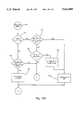
- Radio frequency circuit 50is mounted within housing 35 of rear view mirror 30.
- Radio frequency circuit 50includes a mixer 51 which mixes a reference frequency 52 and a signal on an output 55 of a controllable divider 58.
- Reference signal 52is a fixed frequency signal which may be generated from a commercially available color burst type T.V. crystal generating approximately a 4 MHz signal.
- the controllable divider 58may be a commercially available 145151 or 145106 integrated circuit, or any other suitable controllable divider.
- the output signal from mixer 51will contain DC and AC components.
- a low pass filter 53is provided to remove AC signals from the output signal of mixer 51.
- Controllable divider 58receives the output signal from fixed divider 57 and provides an output signal having a frequency determined by a control byte received from output terminals 1021 (FIG. 9b) of microcontroller 100 via bus 65.
- Mixer 59also receives the output of a low noise amplifier 60 which amplifies signal energy A and B received by antenna 62 and transmitted from keyless entry key fob 21 and remote transmitter 40a, respectively. If the garage door opener is not used with a keyless entry system, low noise amplifier 60 is not required, and consequently, a resistor, pin diode, or any other suitable conditioning circuit could be used to connect antenna 62 to mixer 59.
- a demodulator 64which may be a resistor and a capacitor integrator circuit will further condition the output of low pass filter 63 to provide a DC level which the microcontroller will use to determine when RF data is being received by transceiver 50 as described below with respect to FIGS. 15a-15d.
- a microcontroller 100controls the circuit operation and may be a commercially available IC 68HC05B6, which includes a nonvolatile memory 115; however, any appropriate microprocessor may be used.
- FET switch 61receives a transmit/receive select signal from output terminal 1022 of microcontroller 100 via conductor 66.
- the output of demodulator 64is provided to the RF data input terminal 1023 of the microcontroller via line 67.
- the control input to divider 58is coupled to output terminals 1021 via conductors 65.
- a courtesy input 79is coupled to interrupt input terminal 1008 of microcontroller 100 via pull up resistor 80 and a diode 81.
- the courtesy input 79has a high logic level when all the vehicle doors are closed. Pull up resistor 80 thus holds the cathode of diode 81 at a high logic level when the vehicle doors are closed.
- courtesy input 79When one or more of the vehicle doors are open, courtesy input 79 will have a low logic level thereon, which will cause the cathode of diode 81 to be at a low logic level.
- Pull up resistor 82holds input terminal 1008 high until the cathode of one of the diodes, 69, 81, 73, or 77, is brought to a low logic level, which will cause the diode having a low logic level on the cathode to be forward biased to pull input terminals 1008 to a low logic level.
- Switch 71is connected to left maplamp input terminal 1007 and switch 75 is connected to right maplamp input terminal 1009.
- Input terminals 1009 and 1007 of microcontroller 100will have low logic levels thereon when switches 75 and 71, respectively, are closed.
- Input terminal 1006is connected to the courtesy input via conductor 79, and it will have a low logic level thereon when the courtesy input is at a low logic level indicating one of the vehicle doors is open.
- the demodulatorwill provide a low logic level to RF input terminal 1023 when RF the output of V.C.O. 54 and a signal received via antenna 62 are at substantially the same frequency. As described below in connection with the flow diagrams of FIGS.
- the microcontroller programis responsive to an interrupt, which will be detected by interrupt terminal 1008 having a low logic level thereon, for reading the input terminals 1006, 1007, 1009, and 1023 to determine the source of the interrupt.
- the microcontrollerwill then control the maplamps, the transceiver, etc., on the basis of which input terminal, 1006, 1007, 1009, or 1023, has a low logic level thereon simultaneously with the interrupt input terminal 1008.
- a bus 83connects a keyless entry output 1005 of the microcontroller to the keyless entry interface circuit 84.
- the keyless entry interfaceprovides an output signal on lead 85 which will lock the doors of the vehicle, or an output on lead 87 which will unlock the doors, in response to a control signal provided through conductor 83 from output terminal 1005.
- a bi-directional bus 89connects microcontroller input/output terminal 1003 to compass circuit 86.
- a particularly effective compass circuitis described in detail in U.S. Pat. No. 4,546,551, issued Oct. 15, 1985, and entitled ELECTRICAL CONTROL SYSTEM, and U.S. Pat. No. 4,424,631, entitled ELECTRICAL COMPASS, issued on Jan. 10, 1984, the disclosures of which are incorporated herein by reference.
- Temperature circuit 88provides an output signal on conductor 94 to the temperature input terminal 1001 of the microcontroller.
- Temperature sensorsmay be provided in the form of thermistors, and temperature circuit 88 may comprise a buffer for interfacing between the sensor(s) and microcontroller input terminal 1001.
- a power supply 96provides a regulated +5 VDC reference potential on terminal 97 and a regulated +12 VDC reference potential on terminal 98. Circuits for providing the regulated voltages are well known and accordingly will not be described in further detail herein.
- Power supply 96receives power from the vehicle battery via a conductor 99 and a ground conductor 101.
- a vehicle ignition signalis applied to power supply 96, as well as to microcontroller 100 at ignition sense input terminal 1002, through conductor 103.
- a signal provided through conductor 105is applied to a reverse sense input terminal 1004 of the microcontroller so that the microcontroller may determine if the vehicle is in reverse.
- a front photocell 108provides an indication of the ambient light level on the front of mirror 39.
- a resistor 109is connected in series with photocell 108 between the +5 VDC reference potential and ground to provide a voltage divider.
- the junction of the photocell 108 and the resistor 109is coupled to the front photocell input terminal 1010 of the microcontroller 100 via an analog-to-digital (A/D) converter 102.
- a rear photocell 111similarly provides an indication of the ambient light level at the rear side of the mirror assembly 30.
- a resistor 113is provided in series with the rear photocell 111 between the +5 VDC battery potential and ground.
- the junction of photocell 111 and resistor 113is coupled to the rear photocell input terminal 1011 of microcontroller 100 via an A/D converter 112.
- Input terminals 1010 and 1011are converted from analog-to-digital signals by A/D converters 102 and 112 respectively in order provide the microcontroller with an actual indication of the front and rear light levels.
- a nonvolatile memory (NVM) 115is connected to input/output terminal 1012 of microcontroller 100 via a bidirectional bus 115', and retains status information when the ignition of vehicle 20 is turned off.
- FET switches 116 and 121are controlled by output signals from terminals 1013 and 1014 of the microcontroller.
- Switch 116will actuate left maplamp 117 when either the left map lamp switch 71 is actuated or courtesy input terminal 1006 changes state.
- Switch 121will actuate right maplamp 120 when either the right maplamp switch 75 or courtesy input terminal 1006 changes state.
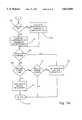
- the main program for microcontroller 100is shown in FIG. 10.
- the programbegins with an initialization block 200 in which the input ports to microcontroller 100 are configured, an internal random access memory (RAM) is cleared, and the control program is loaded from an internal read-only memory (ROM) into the RAM.
- RAMrandom access memory
- ROMread-only memory
- the programwill always be initialized following a disconnection of the battery which causes power supply 96 (FIG. 9a) to be interrupted.
- the microcontrollerwill operate in a "stop mode" which will be interrupted by input terminal 1008 going to a low logic level or by the timer interrupt described below with respect to FIGS. 15a through 15d. Interrupt terminal 1008 will be pulled to a low logic level by switches 71 and 75, courtesy input 79, or RF circuit 50.
- the transmitter/receiver output terminal 1022will be set to the receive mode (switch 61 will be turned off).
- the frequency synthesizer of radio frequency (RF) transceiver 50(FIG. 9a), including mixer 51, low-pass filter 53, voltage controlled oscillator 54, divide-by-256 divider 57, and controllable divider 58, will set voltage controlled oscillator 54 to output a signal having the frequency of the key fob 21 of the keyless entry, as indicated in block 203. This frequency may be 315 MHz, but any satisfactory frequency could be used.
- the microcontroller programwill then proceed to the switch check subroutine SWCHK, which is described below in connections with FIGS.
- the microcontroller programwill determine, as indicated by block 205, whether the ignition is on or off. If ignition input terminal 1002 to the microcontroller indicates the ignition is not on, the program will return to the subroutine SWCHK. If it is determined in the test of block 205 that the ignition is on, the program will proceed to block 206 wherein temperature data will be retrieved from temperature circuit 88 by reading input terminal 1001. Compass data will be retrieved from compass circuit 86 by reading input terminal 1003 or by heading information calculated by the microcontroller using the microcontroller flow diagrams set forth in U.S. Pat. No.
- the ignition voltage supplied via conductor 103will be determined by microcontroller 100 reading input terminal 1002, and the status indicated thereby will be saved as indicated by block 215.
- the microcontrollerwill determine whether the ignition status saved in block 215 indicates that the ignition is on or off as shown by block 216. If the ignition is on, the display driver 130 (FIG. 9b) will be turned on, as indicated by block 217. However, if the ignition status indicates that the ignition is off, the display hardware 130 will be turned off, to conserve energy, as indicated by block 218.
- the microcontrollerwill next determine whether left maplamp switch 71 is closed, as shown in test block 219.
- switch 71the microcontroller will determine if the switch was just closed by test block 220. If switch 71 just closed, the left maplamp will be toggled to its opposite state. Thus, if the left maplamp was off it will be turned on, and if it was on it will be turned off. The microcontroller program will then proceed o the test indicated by block 222. In block 222, the microcontroller program determines whether right maplamp switch 75 is closed. If not, the program will proceed to block 225 as shown by port F. If switch 75 is closed, the program will determine whether switch 75 just closed as indicated by block 223. If switch 75 was not just closed, the program will proceed to block 225.
- GDO switch 127If GDO switch 127 is closed, the microcontroller program proceeds to subroutine GDO as indicated by block 230. Subroutine GDO is described below with respect to FIGS. 12a, 12b, and 12c. Following subroutine GDO the program will return to the main program as indicated by block 231. The various subroutines typically feed back into the main program at V (FIG. 10) and the main program proceeds to block 205.
- the microcontrollerdetermines that the identification code for driver one was last received, the mirror information stored in NVM 115 for driver one is retrieved, as indicated by block 251. Once the mirror information for driver one is retrieved, the microcontroller proceeds to the test of block 238. If, however, the microcontroller determines in block 236 that the last valid code received is not the identification code for driver one, then the microcontroller retrieves the mirror parameters for driver two stored in NVM 115, as indicated by block 237. The microcontroller then proceeds to the test of block 238.
- the microcontrollerdetermines whether the doors are to be locked. If the microcontroller receives a signal to lock a door, or doors, from the keyless entry, it will provide an appropriate control signal on output terminal 1005 for the keyless entry interface 84. Keyless entry interface 84 will in turn provide a logic signal on conductor 85 which will cause a door, or doors, of the vehicle to lock. As indicated by block 240, the microcontroller will then return to the main program and proceed to the "ignition on" test of block 205 therein.
- the microcontrollerwill proceed to the test indicated by block 241 wherein it will determine whether an unlock command was received from the keyless entry key fob. If an unlock command was received, the microcontroller will provide an appropriate output control signal on output terminal 1005 for the keyless entry interface 84, which will in turn provide the appropriate logic signal on conductor 87 to cause a door, or doors, of the vehicle to unlock.
- the microcontrollerwill return to the main program at block 205 through port V. If the microcontroller program determines in block 235 that a valid keyless identification code was not received, it proceeds to the test of block 245 through port G. Alternately, if the microcontroller program determines in the test of block 241 that an unlock command was not received, the program will proceed to the test of block 245. In block 245, the program determines whether the EAM train switch 124 and the GDO switch 127 are simultaneously closed. If both switches 124 and 127 are closed, then the program will proceed to subroutine KTRAIN wherein a new key fob code can be trained. The KTRAIN subroutine is described below with respect to FIGS. 14a and 14b. Following the completion of the subroutine KTRAIN, the program returns to the main program at block 205 through port V, as indicated by block 247.
- the programproceeds to the stop mode, indicated by block 248, to wait for an external interrupt as indicated by block 249.
- the microcontrollerUpon receiving an external interrupt, the microcontroller will return to the main program at block 205 through port V.
- the stop modethe microcontroller program waits for an interrupt from one of switches 71 and 75, RF transceiver 50, and courtesy input 79, which are tied to the interrupt input terminal 1008 of the microcontroller via their respective diodes (see FIGS. 9a and 9b).
- the microcontroller programwill next read the channel selector switch input terminal 1020 connected to channel switch 136, which in the mirror embodiment illustrated in FIG. 3, could be provided by a 3-position slide switch located on the back of the mirror (see 43 in FIG. 3).
- the channel selector switchwill be positioned to indicate channel 1, channel 2, or channel 3, is selected, each channel representing a different control signal. In this manner, the garage door opener may generate as many as three different garage door mechanism control signals.
- the GDO bit stream corresponding to the respective channel selected by switch 136(FIG. 9b) will be read into the microcontroller from NVM 115.
- the GDO bit streamis a control signal made up of eight to sixteen bits which is transmitted repeatedly within the control signal to uniquely identify the receiver which is to be controlled thereby.
- the microcontrollerdetermines the eight to sixteen bits to be transmitted by sampling the RF input when the microcontroller program and the transceiver 50 are being trained to the remote transmitter signal B generated by remote transmitter 40, as described below.
- the microcontrollerwill then place transceiver 50 in its transmit mode by providing the appropriate logic level on output 1022 as indicated by block 263.
- the appropriate oscillator frequencywill be output by V.C.O. 54
- the repeating GDO bit streamwill be modulated onto the output of V.C.O. 54 by switch 61, and the transmission will be acknowledged by an appropriate indication on display 131.
- the microcontrollerAfter transmitting a remote control signal, the microcontroller provides an appropriate logic signal on output terminal 1022 to return transceiver 50 to the receive mode as indicated in block 265. In block 266, the garage door opener returns to the. SWCHK subroutine at block 231 (FIG. 11b) to return to the main program.
- the microcontroller 100determines that switch 127 was closed more than momentarily by the test of block 260, it will proceed to the test of block 267 wherein it will determine whether switch 127 has been closed for more that 5 seconds. If switch 127 has not been closed for 5 seconds, the program returns to the SWCHK subroutine as shown by block 266. If the switch has been pressed for 5 or more seconds, the program proceeds to the test of block 268 via port 3A. In block 268, the microcontroller determines which channel is selected by the 3-position slide switch 136.
- the microcontroller programthen proceeds to block 269 wherein the frequency output by V.C.O. 54 is set to its lowest frequency, which, for example, can be 290 MHz.
- the programdetermines whether radio frequency data is present at data input terminal 1023 of the microcontroller. If data is present at the data input, as indicated by a low logic level on input terminal 1023, the microcontroller program proceeds to the test of block 271 wherein it determines if input terminal 1023 is at its minimum. The amplitude minimum will occur when the output of the voltage controlled oscillator 54 is at the same frequency, or substantially the same frequency, as the signal output from low noise amplifier 60, thus eliminating any DC component from the oscillating signal.
- the frequency supplied by V.C.O. 64is increased by 1 MHz by changing the control byte at output terminal 1021 of microcontroller 100.
- the programdetermines if the frequency that results from adding 1 MHz to the previously output frequency results in the highest frequency V.C.O 54 will generate being output therefrom, for example 415 MHz. If the frequency output by V.C.O. 54 is not the highest frequency, the microcontroller program returns to block 270. If the frequency output by the V.C.O. is determined to be its highest value by block 273, the microcontroller will acknowledge an unsuccessful train sequence by providing an appropriate output indication to the display. The vehicle operator will thus be aware that microcontroller 100 has not trained to the signal of remote transmitter 40 (FIG. 2). Thereupon, the microcontroller program will return to the SWCHK subroutine.
- microprocessor 100next samples the RF input terminal 1023 to determine logic level transitions and detects thereby eight data bits.
- the control signal transmitted by remote transmitter 40will have eight to sixteen bits which are modulated on the carrier signal and repeated periodically.
- the programmust determine which bits are repeating, and store these repeating bits, to transmit a control signal which will be effective to activate mechanism 40.
- the sampled bitsthus represent eight bits transmitted by remote transmitter 40a.
- the sampled data bitsare stored in a memory within microcontroller 100.
- the microcontroller programthen proceeds through port 4A to block 279 wherein the RF input terminal 1023 is again sampled to determine the logic level transitions, and the next eight bits which are represented thereby.
- the microcontroller programdetermines whether the first stored input bit stream representing equals the second input bit stream. If the first and second input bit streams are not equal, the microcontroller will store the second input bit stream in the microcontroller memory as the first input bit stream, and return to block 279, wherein the next input bit stream will be sampled as the second input bit stream.
- the microcontroller programwill compare sequential bit streams of eight bits, then sequential bit streams of nine bits, then sequential bit streams of ten bits, etc., until the program finds two consecutive bits streams that are equal in the test of block 280. The program will then store the bit stream which it samples in two consecutive samplings in a nonvolatile memory location associated with the selected channel (on switch 136) as indicated in block 282.
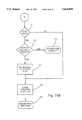
- the subroutine for setting the electrically adjustable mirroris the EAM routine set forth in FIGS. 13a, 13b, and 13c.
- the microcontrollerwill first read inputs from photocells 108 and 111 via the front photocell and rear photocell input terminals 1010 and 1011 as indicated by block 290. The average level received at each of these inputs will be computed as indicated by block 290.
- the microcontroller programwill determine which of four ambient light regions the vehicle is in according to the averaged levels. These are preset regions which are determined from the average levels of the front and rear photocells; for example, the average of the front and rear averages could be used. Of course, more than four ambient light regions may by provided.
- the microcontrollerwill preferably use the average level on input terminals 1010 and 1011 so that the mirror will not respond to brief changes in the light received by the front and rear photocells 108 and 111. Accordingly, the average levels of inputs 1010 and 1011 should not change significantly until a light change is sensed by photocell 108 or photocell 111 for 5 to 15 seconds.
- input terminal 1015will be read to determine if EAM train switch 124 (See FIG. 9b) is closed. If switch 124 is open, the program will proceed through port I to the test of block 305 described below. If EAM train switch 124 is closed, the program of microcontroller 100 will place a control signal on output terminal 1018 which will set the mirror to the first level of reduced reflectivity, as indicated by block 293. The microcontroller program will again determine whether or not the EAM train switch 124 is open as indicated by block 294. The program will remain at this position in the subroutine until the user releases switch 124. Upon the EAM train switch being released, the microcontroller program will clear an internal train counter as indicated by block 295. The program then proceeds via port J (FIGS.
- a second EAM train switch closureindicates the vehicle operator wants the mirror to be trained to the current parameters, that is, the ambient light region determined by the information read as indicated by block 291, the glare threshold at the time the EAM switch was closed the first time, and the level of reflectivity at which the mirror is currently set.
- Microcontroller 100will accordingly determine whether the driver one is operating the vehicle, as indicated by the test of block 297.
- the microcontrollermay also and preferably determine the identity of the driver from the identification code transmitted by the keyless entry key fob last used to access the vehicle. Another method of determining the identity of the driver is to provide a switch which corresponds to each driver. If driver one is operating the vehicle, the program of microcontroller 100 will store in NVM 115, at a location which corresponds to driver one, the ambient light region determined in block 291, the current glare tolerance, and the current reflectivity level.
- Each ambient light regionhas an associated glare tolerance and reflectivity. These parameters are preset at default values which are stored in nonvolatile memory 115 until a vehicle operator sets their own preferred parameters.
- a glare levelwill be determined by subtracting the average level of input terminal 1011 from the average level of input terminal 1010.
- the glare thresholdis the difference between the front and rear ambient light levels which indicates to the microprocessor that the mirror reflectivity should be adjusted. The setting of the glare threshold should be made according to the difference between the actual signal levels supplied by the front and rear photocells 108 and 111 when EAM switch 124 is closed by the operator, which is detected by the microcontroller program as indicated by block 292.
- the difference between the actual signal levels supplied by the front and rear photocells when switch 124 is closed by the operator to initiate trainingrepresents the actual threshold at which the driver experiences discomfort, and accordingly represents the point at which the driver wants the reflectivity of the mirror adjusted.
- the average levels of the signals supplied from photocells 108 and 111should be used to determine the glare level for purposes of causing automatic adjustment of the mirror, as brief changes in the light received at the front photocell should not cause the reflective level of the mirror to change.
- the programdetermines in block 297 that driver one is not operating the vehicle, it will store the ambient light region which was determined in block 291, the glare threshold to be associated with that ambient light region, and the reflectivity level to be associated with that ambient light region, in NVM 115 at a location allocated for driver two.
- the parameters stored in NVM 115will be used by the microcontroller to set the reflectivity level of EAM 135 according to the identity of the driver.
- the identity of the driver onewill be used by the program as long as the last valid identification code received from a keyless entry key fob was the identification code stored in NVM 115 for driver one.
- the microcontrollerwill operate using the identity of driver two if driver two's identification code was last valid identification code received from a keyless entry key fob. Following storage of the vehicle operator's parameters, microcontroller 100 will proceed to block 305 as described below.
- the microcontroller programdetermine EAM train switch 124 (FIG. 9b) was not closed, in block 296, it will increment the five second train counter, which was cleared in block 295, as indicated in block 300.
- the programwill determine if five seconds have elapsed as indicated by the train counter. If not, the microcontroller program will again determine if EAM train switch 124 is closed. If the EAM train switch 124 is not closed before the five second counter times out, as determined in block 301, the program will determine whether or not the level of reflectivity of the electronically adjustable mirror is set to its maximum attenuation.
- the level of reflectivitywill be set to the default level preset at the factory, as indicated by block 303, and the program will proceed through port K.
- the mirrormay for example have four levels of reflectivity, which levels will be used for each of the ambient light regions. However, more or less than four levels of reflectivity may be provided. If the level of reflectivity is not at its maximum attenuation, the microcontroller program will increase the reflectivity attenuation as indicated by block 304, and return to the test of block 296 to determine whether or not the driver has closed the EAM train switch.
- the level of reflectivity on EAM 135 when the switch is closed(at block 296) will be stored as the current level of reflectivity parameter in block 298 or 299, and the program proceeds via port I to determine whether driver one is operating the vehicle by the test of block 305 (FIG. 13c). If driver one is not determined to be controlling the vehicle, the EAM parameters for driver two associated with the ambient light region determined in block 291 will be retrieved by microcontroller 100 from NVM 115, as indicated by block 306. If it is determined in block 305 that driver one is operating the vehicle, then the electronic adjustable mirror parameters for driver one associated with the ambient light region determined by block 291 will be retrieved from NVM 115.
- the programthen tests to determine whether the vehicle is in forward or reverse by polling input terminal 1004 as indicated by the test of block 308. If the vehicle is in reverse, electronically adjustable mirror 135 will be set to its maximum reflectivity. If the vehicle is not in reverse, the microcontroller program determines whether the mirror should be dimmed by the test of block 309. This is determined according to the parameters retrieved in block 306 or 307, and the average ambient light levels sensed by photocells 108 and 111. If the mirror should not be dimmed, as determined by block 309, the program will determine whether the mirror should be cleared, for example, because the ambient light level is decreasing.
- the mirrorwill be set to the maximum level of reflectivity as indicated by block 311, and the subroutine program will return to the SWCHK subroutine. If the mirror should not be cleared, as determined by block 310, the microcontroller will also return to the SWCHK subroutine, and then to the main program through port V. If the microcontroller program determines as indicated by the test of block 309 that the mirror should be dimmed because the retrieved glare tolerance threshold has been exceeded, microcontroller 100 will dim mirror 135 to the retrieved level of reflectivity, as indicated by block 312, and then return to the SWCHK subroutine as indicated by block 313.
- the keyless entry train routine, KTRAINis set forth in FIGS. 14a and 14b. This subroutine will be entered whenever both the EAM train switch 124 and the GDO switch 127 are closed simultaneously, as determined in the switch check (SWCHK) subroutine. A separate "RKE" switch could, however, be provided for initiating a remote keyless entry retrain.
- Microcontroller 100controls display 131 to output a "train” indication as indicated by block 320. Following a train indication, a 10 second counter is cleared as shown by block 321. The 10 second counter is then incremented as indicated by block 322. The microcontroller program then determines whether 10 seconds has elapsed as indicated by block 323. If it has, the program proceeds to the test of block 336 via port M (FIGS.
- the microcontrollerwaits for a valid identification code. If a valid code is received before the ten second timer times out, the microcontroller will proceed to the test of block 325. In block 325, it is determined whether the received identification code matches the code presently stored in NVM 115 for driver one. If the received identification code matches the code stored in NVM 115 for driver one, the microcontroller clears the mirror parameters stored for that driver, computes the checksum, and stores the received code in the memory location allocated for driver one's identification code, as indicated in block 327. The checksum is the sum of the bits of the code which is used to check the data for accuracy. The program will then proceed to the operation of block 336 below through port M.
- the program for the microcontrollerdetermines in block 325 that the received identification code does not match the code presently stored in NVM 115 for driver one, it will proceed through port L and determine whether the identification code matches the code presently stored in NVM 115 for driver two, as indicated in block 328. If the identification code received and the identification code currently stored for driver two match, the microcontroller proceeds to clear driver two's EAM parameters, as indicated in block 329. In block 330 the microcontroller then computes the checksum of the identification code, and stores the received identification code and checksum in the NVM location associated with driver two's identification code. The program for the microcontroller then proceeds to block 336 below.
- the programwill determine where the last entered code was stored in block 331. If last stored identification code is currently in the memory location corresponding to driver two's identification code, the program will clear driver one's electronically adjustable mirror preferences, as indicated in block 332. In block 333, the microcontroller program will then compute the code checksum, and store the received identification code and checksum in the memory location allocated for driver one's code.
- the microcontrollerwill clear driver two's electronically adjustable mirror data in block 334, compute the code checksum, and store the received identification code and checksum in the memory location allocated for driver two's code, as indicated in block 335.
- the microcontrollerturns off the train indicator on display 138 and in block 337 it returns to the SWCHK subroutine of FIGS. 11a-11c.
- the EAM subroutinestores new identification codes and clears stored EAM parameters, and if the new code fails to match either stored code, the program stores the received identification code in the opposite location of the last stored code.
- a timer interrupt subroutinediagrammed in FIG. 15a is provided.
- This interrupt routineinterrupts the stop mode (FIG. 11c) at regular intervals to receive the identification code of the keyless entry signal or to update the compass reading.
- the programfirst determines if the ignition is on as indicated by block 351. If the ignition is on, as determined by reading microcontroller input terminal 1002, the microcontroller program will proceed to the compass subroutine, which is preferably the subroutine disclosed in U.S. Pat. No. 4,546,551, issued Oct. 15, 1985, and entitled ELECTRICAL CONTROL SYSTEM, the disclosure of which is incorporated herein by reference.
- the microcontrollerwill also preferably provide compass calibration as disclosed in issued application 07/054,885, filed May 27, 1987, and entitled VEHICLE COMPASS WITH AUTOMATIC CONTINUOUS CALIBRATION, the disclosure of which is incorporated by reference. If the ignition is off, the keyless timer subroutine 352 of FIG. 15b will be executed.
- the microcontroller programfirst determines in block 354 whether or not the radio frequency input terminal 1022 (FIG. 9b) to the microcontroller is at a high or low logic level. If a radio frequency input signal is received by RF circuit 50, a low logic level will be outputted by demodulator 64, which will cause the program to proceed to the test of block 355. In block 355, it will determine whether an internal "inputting code” flag has been set. The "inputting code” flag tells the microprocessor program that the identification code is being received at RF input terminal 1023 so that both high and low data bits will be sampled and processed until the entire identification code is received.
- the microcontrollerwill process a high logic level to determine the pulse width thereof, as indicated in block 356. If the inputting code flag is not set, the program will determine in block 357 whether an internal "idle" flag is set. If the "idle” flag is set, the program proceeds to block 358 wherein the "inputting code” flag is set, and then the occurrence of a high logic level is processed to determine the pulse width thereof in block 356. If the microcontroller program determines in block 357 that the idle flag was not set, it will proceed to block 365 through port B.
- microcontroller 100determines in block 354 that radio frequency input terminal 1023 is low, it proceeds to block 359 wherein it determines whether the "inputting code” flag is set. If the "inputting code” flag is not set, the microcontroller program proceeds to block 365. If the microcontroller determines in block 359 that the "inputting code” flag is set, and thus the microcontroller is receiving a code, it will provide an internal indication that a low logic level is present as indicated in block 360, and thus the high logic level has ended, and proceed to block 371 via port N.
- microcontroller 100determines whether the "idle flag” is set. If the "idle flag” is set, the microcontroller program returns from the interrupt to the main program as indicated in block 369. If the "idle flag” is not set, as determined in block 365, the idle time is incremented in block 366. The program next determines whether the idle timer is equal to a preset idle time as indicated by block 367. It determines the idle timer is not equal to the preset idle time, it returns from the interrupt as indicated by block 369. If the microcontroller program determines the idle timer equals the preset idle time, the "idle flag" is set as indicated by block 368 and the microcontroller returns from the interrupt, as indicated by block 369. The purpose of the idle timer is to insure that bits are ignored until a preset idle period, which is the period between identification code transmissions in the keyless entry signal, has elapsed.
- the programproceeds to block 371 of the TIMER INTERRUPT subroutine shown in FIG. 15d.
- the microcontroller programfirst determines whether the bit to be processed is valid in block 371. If it is an invalid bit then the microcontroller will clear the inputting code flag in block 375 and return from the interrupt. If the bit is valid, that is, it has the proper pulse width for either a zero or a one bit, as determined in block 371, the microcontroller will determine whether all of the bits have been read as indicated by block 372.
- the microcontroller programwill return from the interrupt as indicated by block 373 to await the next bit. If the microcontroller program determines in block 372 that all the bits have been received, the microcontroller program will first set an internal flag, indicating a valid code has been received, as indicated by block 374, and then clear the "inputting code” flag as indicated by block 375. The microcontroller program will then return from the interrupt as indicated by block 376.
- FIG. 16shows a trainable universal garage door opener block diagram which can be provided as a stand alone unit or integrated into the mirror package shown in FIGS. 1-8.
- This unitcan be provided as an accessory which may be located within a structural accessory, such as a visor, a roof console, or a mirror.
- the unitoperates in substantially the same manner as the RF transceiver 50 and microprocessor 100 of the circuit illustrated in FIGS. 9a and 9b, and its software described above and, accordingly, will only be briefly described below.
- the unit illustrated in FIG. 16includes a transceiver 500 which comprises a reference frequency source 389 which may be generated by, for example, a color burst oscillator for a T.V. operating at approximately 4 MHz.
- the reference frequencyis combined in a mixer 390 with the control frequency provided by a programmable divider 394.
- the output of the mixeris filtered by a low pass filter 391 and is provided as a control input for a voltage control oscillator 392.
- the output signal of the voltage control oscillatoris provided to a second mixer 397.
- the output signal of V.C.O 392is also applied to divide-by-256 divider 393.
- the output signals of divider 393are apparent to an input of a controlled divider 394, the output of which is coupled to the second input of mixer 390.
- Controllable divider 394receives an eight bit control signal from the output terminals 415 of a microcontroller 400.
- the output signals of V.C.O. 392are employed to actuate a garage door mechanism and are coupled through a F.E.T. switch 395 when microcontroller 400 provides a transmit enable signal at output terminal 414 to switch 395 which modulates the binary data supplied from output 414 of microcontroller 400 with the frequency output signals of V.C.O. 392.
- Signalsare received by an antenna 404 of transceiver 500 and amplified by a low noise amplifier 396 before being mixed in mixer 397.
- the low noise amplifieris optional, and would only be required if transceiver 500 is also used to receive keyless entry signals.
- the output of mixer 397is filtered by a low pass filter 398 coupled to a demodulator 399 which demodulates the output of low pass filter 398 to provide binary signals which are applied to the RF input 413 of microcontroller 400.
- Microcontroller 400may be commercially available 6805P1 or 6805J1 ICs, but any suitable microprocessor could be used. Additional control inputs and outputs may be received through input/output 412 from interface circuitry 401.
- interface circuit 401may include a channel selection switch which provides which one of a plurality of control signals is to be trained or transmitted.
- An LED output 402 connected to microcontroller output 411provides an indication to the user that microcontroller 400 has trained or failed to train to a remote control signal, and that it is currently transmitting signals.
- a transmit train switch 403 coupled to microcontroller input 410controls the microcontroller to either transmit a signal via transceiver 500 or to train to the control signal of a remote transmitter for actuating a garage door mechanism.
- microcontroller 400will now be described with respect to FIGS. 17a, 17b, 17c and 17d.
- the program for the operation of microcontroller 400is substantially the same as that for microcontroller 100 as described above with respect to FIGS. 12a, 12b, and 12c, and accordingly, FIGS. 17a, 17b, 17c, and 17d are described only briefly below.
- the ports and registers of microcontroller 400are initialized and the internal RAM is cleared.
- the internal RAM of the microcontrollerwill then receive programming code for its operation from a ROM which may be part of the microprocessor or external thereto.
- the microcontroller programwill turn the transceiver switch 395 to its receive mode by providing the appropriate logic level on output 414.
- the microcontroller programwill supply an 8-bit data byte to output 415 which will be supplied to controllable divider 394 and result in V.C.O. 392 generating a 315 MHz signal.
- the 315 MHz signalis provided as an example, and the output of the oscillator should be that of the carrier frequency of the keyless entry signal when the transceiver is in its idle reception mode.
- any appropriate RF frequencycould be used for the keyless entry carrier signal, and the output of the V.C.O should correspond thereto.
- transceiver 500is not used to receive keyless entry signals, the V.C.O. need not generate the 315 MHz signal during an idle mode.
- the microcontroller programdetermines whether radio frequency data has been received. If RF data has been received at input 413, the microcontroller program will process the radio frequency data, as indicated in block 449.
- the microcontroller programwill determine whether or not transmit switch 403 has been closed, as indicated in block 454. If transmit switch 403 is closed, the microcontroller program will determine as indicated by block 453 whether any radio frequency data has been received.
- the microcontrollerwill process data at input 413, as indicated in block 449, when the microcontroller program determines RF data is present at the RF input 413, as indicated by block 453.
- the programwill proceed through port 2B to block 455 where the microcontroller program will determine whether the switch has been closed momentarily, which for example could be a period of less than two seconds. If switch 403 has been pressed momentarily as determined in block 455, the microcontroller will retrieve the data stored in an internal or external NVM of microcontroller 400 at a location corresponding to the channel indicated by the channel selector switch in interface circuit 401, as indicated in block 456.
- the microcontroller programretrieves a garage door opening bit stream from the NVM location associated with the channel selected by the channel selector switch.
- the microcontroller programwill place transmitter/receiver switch 395 in the transmit mode, as indicated in block 458.
- the microcontroller programwill transmit the retrieved control code, and acknowledge the transmission by turning on LED 402.
- the transmitter/receiver switchwill be turned off as indicated by block 460 to place the transceiver in the receive mode, and the microcontroller program will proceed to block 453 shown in FIG. 17a. If the switch has not been pressed momentarily, as determined in block 455, the microcontroller will determine whether the switch has been pressed for longer than five seconds, as indicated in block 460. If switch 403 has not been closed for five seconds or more, the microcontroller program will return to block 453 in FIG. 17a.
- the microcontroller programwill proceed through port 3B to determine, as indicated by block 462, which channel is selected by checking the channel selector switch.
- the microcontroller programwill next set V.C.O. 392 to its lowest output frequency, for example 290 MHz.
- the microcontroller programdetermines whether a demodulated radio frequency signal has been received at the data input to the microcontroller as indicated by block 464.
- the microcontrollerwill determine whether data input terminal 413 is at its minimum, as indicated by the test of block 465. This may be done, as described above with respect to FIG. 12b, by converting the output of demodulator 399 to a digital value or by shifting the frequency of the V.C.O. by 500 KHz to determine if the logic level on input terminal 413 changes. If the RF data input level is not at the minimum, as determined in block 465, or if the RF data is not present at input terminal 413, as determined by the test indicated by block 464, the frequency output by V.C.O. 392 will be incremented by 1 MHz by changing the output on terminals 415, as indicated in block 467.
- microcontroller 400will acknowledge an unsuccessful training sequence, as indicated in block 469, by, for example, flashing LED 402. The program will then return through port 1B to block 453. If the frequency output by V.C.O. 392 is not at the highest frequency, the microcontroller program will return to block 464 to repeat the tests of blocks 464 and 465, and operation of block 467, until either the V.C.O. reaches its highest output frequency as indicated by the control byte, or the RF data input 413 is at its amplitude minimum, as determined from the input terminal 413.
- the microcontrollerstores the control byte provided on output 415 in the nonvolatile memory location associated with the selected channel, as indicated in block 470 (FIG. 17c).
- This byterepresents the frequency output by the V.C.O. 392 which is substantially equal to the carrier frequency of remote control 40a (as shown in FIG. 2) for the garage door control mechanism 40.
- block 471after the carrier frequency has been determined and while the V.C.O.
- microcontroller 400will store the sampled bit stream, and proceed through port 4B to block 473.
- the microcontroller programwill sample a second digitized bit stream as indicated by block 473.
- the microcontroller programwill then test to determine in block 474 whether the first stored bit stream equals the second stored bit stream.
- the programmay, for example, sample the RF input terminal 1023 (FIG. 9b) to detect transitions between low and high logic levels.
- the microcontroller programmay sample the first sixteen transitions, and store eight corresponding bits. The microcontroller program may then sample the next sixteen transitions, to determine the next eight bits. If these eight bit sequences are not equal, the program would then sample the next eighteen transitions and store a corresponding nine bits. After sampling eight bit bit streams, the microcontroller would then sample the RF input terminal to determine the next eighteen transitions, thereby determining the next nine bits. The program would repeat this sampling until two consecutive bit sequences are identical. Thus if the first bit stream does not equal the second, the second input stream is stored in memory as the first input bit stream. The next sampled bit stream will then be inputted as the second input bit stream.
- the microcontrollerwill again test to determine whether the first input bit stream equals the second inputted bit stream in block 474. This cycle will continue until the first input bit stream and the second input bit stream are equal.
- the microcontroller programstores the repeating bit stream in a memory location associated with the selected channel as indicated by block 476.
- a successful train sequenceis displayed to the user as indicated by block 477 and the microcontroller and transceiver 500 will then transmit the stored control signal to actuate the garage door garage door mechanism, as indicated by block 477.
- the microcontrollerwill then return to the beginning of the program at block 450 in FIG. 17a.
- the transceiver and the control circuittherefore (FIGS. 9a, 9b, and 16) generate a remote control signal for a garage door mechanism using circuitry provided as part of a structural accessory. Because the transceiver and the control circuitry therefore trains to the signal of a remote control using circuitry provided within the structural accessory, physical modification of the structural accessory is not required in order to generate a control signal which will be effective to actuate the control mechanism. It can also be seen that the transceiver 50 (FIG. 9a) and transceiver 500 (FIG. 10) receive both a keyless entry control signal and a remote control signal from transmitter 40 thereby eliminating circuit redundancy in providing both electrical accessories.
- the systemcan additionally include a control circuit for controlling an information display 135 (FIG. 9b) using the control circuit for the transceiver. Furthermore, a mirror with a degree of reflectivity set according to the parameters preferred by each driver of vehicle was seen which uses the transceiver control circuit. Thus a flexible and efficient system is set forth for providing vehicle options.
Landscapes
- Engineering & Computer Science (AREA)
- Multimedia (AREA)
- Mechanical Engineering (AREA)
- Physics & Mathematics (AREA)
- General Physics & Mathematics (AREA)
- Computer Networks & Wireless Communication (AREA)
- Chemical & Material Sciences (AREA)
- Crystallography & Structural Chemistry (AREA)
- Selective Calling Equipment (AREA)
- Fittings On The Vehicle Exterior For Carrying Loads, And Devices For Holding Or Mounting Articles (AREA)
Abstract
Description
Claims (3)
Priority Applications (13)
| Application Number | Priority Date | Filing Date | Title |
|---|---|---|---|
| US07/567,390US5614885A (en) | 1988-12-05 | 1990-08-14 | Electrical control system for vehicle options |
| US07/792,288US5223814A (en) | 1988-12-05 | 1991-11-14 | Sensor for vehicle accessories |
| US07/989,895US5455716A (en) | 1990-08-14 | 1992-12-10 | Vehicle mirror with electrical accessories |
| US08/055,509US5442340A (en) | 1988-12-05 | 1993-04-30 | Trainable RF transmitter including attenuation control |
| US08/172,642US5475366A (en) | 1988-12-05 | 1993-12-22 | Electrical control system for vehicle options |
| US08/263,263US5479155A (en) | 1988-12-05 | 1994-06-21 | Vehicle accessory trainable transmitter |
| US08/381,087US5691848A (en) | 1988-12-05 | 1995-01-31 | Electrical control system for vehicle options |
| US08/381,551US5661455A (en) | 1988-12-05 | 1995-01-31 | Electrical control system for vehicle options |
| US08/381,470US5699044A (en) | 1988-12-05 | 1995-01-31 | Electrical control system for vehicle options |
| US08/426,052US5646701A (en) | 1990-08-14 | 1995-04-21 | Trainable transmitter with transmit/receive switch |
| US08/459,746US5614891A (en) | 1988-12-05 | 1995-06-02 | Vehicle accessory trainable transmitter |
| US08/461,653US5583485A (en) | 1988-12-05 | 1995-06-05 | Trainable transmitter and receiver |
| US08/749,142US5708415A (en) | 1988-12-05 | 1996-11-14 | Electrical control system for vehicle options |
Applications Claiming Priority (2)
| Application Number | Priority Date | Filing Date | Title |
|---|---|---|---|
| US27964388A | 1988-12-05 | 1988-12-05 | |
| US07/567,390US5614885A (en) | 1988-12-05 | 1990-08-14 | Electrical control system for vehicle options |
Related Parent Applications (1)
| Application Number | Title | Priority Date | Filing Date |
|---|---|---|---|
| US27964388AContinuation-In-Part | 1988-12-05 | 1988-12-05 |
Related Child Applications (10)
| Application Number | Title | Priority Date | Filing Date |
|---|---|---|---|
| US68588091AContinuation-In-Part | 1990-08-14 | 1991-04-15 | |
| US07/792,288Continuation-In-PartUS5223814A (en) | 1988-12-05 | 1991-11-14 | Sensor for vehicle accessories |
| US87436192AContinuation-In-Part | 1988-12-05 | 1992-04-24 | |
| US08/172,642ContinuationUS5475366A (en) | 1988-12-05 | 1993-12-22 | Electrical control system for vehicle options |
| US08/381,551ContinuationUS5661455A (en) | 1988-12-05 | 1995-01-31 | Electrical control system for vehicle options |
| US08/381,087DivisionUS5691848A (en) | 1988-12-05 | 1995-01-31 | Electrical control system for vehicle options |
| US08/381,470DivisionUS5699044A (en) | 1988-12-05 | 1995-01-31 | Electrical control system for vehicle options |
| US08/426,052Continuation-In-PartUS5646701A (en) | 1990-08-14 | 1995-04-21 | Trainable transmitter with transmit/receive switch |
| US08/461,653ContinuationUS5583485A (en) | 1988-12-05 | 1995-06-05 | Trainable transmitter and receiver |
| US08/749,142ContinuationUS5708415A (en) | 1988-12-05 | 1996-11-14 | Electrical control system for vehicle options |
Publications (1)
| Publication Number | Publication Date |
|---|---|
| US5614885Atrue US5614885A (en) | 1997-03-25 |
Family
ID=26959807
Family Applications (5)
| Application Number | Title | Priority Date | Filing Date |
|---|---|---|---|
| US07/567,390Expired - LifetimeUS5614885A (en) | 1988-12-05 | 1990-08-14 | Electrical control system for vehicle options |
| US08/381,551Expired - Fee RelatedUS5661455A (en) | 1988-12-05 | 1995-01-31 | Electrical control system for vehicle options |
| US08/381,470Expired - LifetimeUS5699044A (en) | 1988-12-05 | 1995-01-31 | Electrical control system for vehicle options |
| US08/381,087Expired - Fee RelatedUS5691848A (en) | 1988-12-05 | 1995-01-31 | Electrical control system for vehicle options |
| US08/749,142Expired - Fee RelatedUS5708415A (en) | 1988-12-05 | 1996-11-14 | Electrical control system for vehicle options |
Family Applications After (4)
| Application Number | Title | Priority Date | Filing Date |
|---|---|---|---|
| US08/381,551Expired - Fee RelatedUS5661455A (en) | 1988-12-05 | 1995-01-31 | Electrical control system for vehicle options |
| US08/381,470Expired - LifetimeUS5699044A (en) | 1988-12-05 | 1995-01-31 | Electrical control system for vehicle options |
| US08/381,087Expired - Fee RelatedUS5691848A (en) | 1988-12-05 | 1995-01-31 | Electrical control system for vehicle options |
| US08/749,142Expired - Fee RelatedUS5708415A (en) | 1988-12-05 | 1996-11-14 | Electrical control system for vehicle options |
Country Status (1)
| Country | Link |
|---|---|
| US (5) | US5614885A (en) |
Cited By (106)
| Publication number | Priority date | Publication date | Assignee | Title |
|---|---|---|---|---|
| USD402950S (en) | 1998-01-20 | 1998-12-22 | Prince Corporation | Mirror |
| US5854593A (en)* | 1996-07-26 | 1998-12-29 | Prince Corporation | Fast scan trainable transmitter |
| EP0935226A2 (en) | 1997-11-12 | 1999-08-11 | Prince Corporation | Method and apparatus for storing a data encoded signal |
| US6091330A (en)* | 1998-06-12 | 2000-07-18 | Lear Automotive Dearborn, Inc. | Integrated vehicle remote engine ignition system |
| US6091343A (en)* | 1997-12-18 | 2000-07-18 | Prince Corporation | Trainable RF transmitter having expanded learning capabilities |
| US6125157A (en)* | 1997-02-06 | 2000-09-26 | Rambus, Inc. | Delay-locked loop circuitry for clock delay adjustment |
| WO2001046739A3 (en)* | 1999-12-21 | 2001-11-22 | Bosch Gmbh Robert | Display device |
| US20020175827A1 (en)* | 2001-05-22 | 2002-11-28 | Klein Christopher J. | System and method for remote opening of handicap access doors |
| US6499868B1 (en) | 2000-01-18 | 2002-12-31 | Prestolite Wire Corporation | Vanity mirror lamp assembly with replaceable battery |
| US6556135B2 (en)* | 2000-12-22 | 2003-04-29 | Jan Attring | System for indicating status of a vehicle |
| US20030197595A1 (en)* | 2002-04-22 | 2003-10-23 | Johnson Controls Technology Company | System and method for wireless control of multiple remote electronic systems |
| US20030224729A1 (en)* | 2002-05-28 | 2003-12-04 | Arnold Kenneth David | Interference resistant wireless sensor and control system |
| US20040017292A1 (en)* | 2002-07-29 | 2004-01-29 | Johnson Controls Technology Company | System and method of communicating home security data between a vehicle and a home |
| US6703941B1 (en) | 1999-08-06 | 2004-03-09 | Johnson Controls Technology Company | Trainable transmitter having improved frequency synthesis |
| US20040048622A1 (en)* | 1999-05-26 | 2004-03-11 | Johnson Controls Technology Company | System and method for radio frequency communication with a personal digital assistant in a vehicle |
| US20040100391A1 (en)* | 2002-11-27 | 2004-05-27 | Lear Corporation | Programmable transmitter and receiver including digital radio frequency memory |
| USD496001S1 (en) | 2003-12-17 | 2004-09-14 | Directed Electronics, Inc. | Handheld transmitter |
| US20040193795A1 (en)* | 2003-03-31 | 2004-09-30 | Hitachi, Ltd. | Storage system and method of controlling the same |
| USD496911S1 (en) | 2003-12-17 | 2004-10-05 | Directed Electronics, Inc. | Handheld transmitter |
| USD496913S1 (en) | 2003-12-18 | 2004-10-05 | Directed Electronics, Inc. | Handheld transmitter |
| USD496912S1 (en) | 2003-12-17 | 2004-10-05 | Directed Electronics, Inc. | Handheld transmitter |
| US20050024254A1 (en)* | 2003-07-30 | 2005-02-03 | Lear Corporation | Radio relay appliance activation |
| US20050024255A1 (en)* | 2003-07-30 | 2005-02-03 | Lear Corporation | Bus-based appliance remote control |
| US20050026605A1 (en)* | 2003-07-30 | 2005-02-03 | Lear Corporation | Universal vehicle based garage door opener control system and method |
| US20050024184A1 (en)* | 2003-07-30 | 2005-02-03 | Lear Corporation | Wireless appliance activation transceiver |
| US20050026601A1 (en)* | 2003-07-30 | 2005-02-03 | Lear Corporation | User-assisted programmable appliance control |
| US20050026604A1 (en)* | 2003-07-30 | 2005-02-03 | Christenson Keith A. | Programmable interoperable appliance remote control |
| USD503687S1 (en)* | 2003-10-07 | 2005-04-05 | Lawrence Andrew Hoffman | Illuminated remote control device |
| USD507781S1 (en)* | 2003-12-17 | 2005-07-26 | Directed Electronics, Inc | Handheld transmitter |
| US20050269414A1 (en)* | 2004-06-08 | 2005-12-08 | Curtis Kell | Storing and accessing keys |
| US20060038656A1 (en)* | 2001-12-19 | 2006-02-23 | Lear Corporation | Universal garage door operating system and method |
| US7068181B2 (en) | 2003-07-30 | 2006-06-27 | Lear Corporation | Programmable appliance remote control |
| US7084781B2 (en) | 2003-07-30 | 2006-08-01 | Lear Corporation | Programmable vehicle-based appliance remote control |
| US20060217850A1 (en)* | 2002-11-08 | 2006-09-28 | Johnson Controls Technology Company | System and method for training a transmitter to control a remote control system |
| US20060279399A1 (en)* | 2003-07-30 | 2006-12-14 | Lear Corporation | Remote control automatic appliance activation |
| US20070057810A1 (en)* | 2002-10-08 | 2007-03-15 | Johnson Controls Technology Company | System and method for enrollment of a remotely controlled device in a trainable transmitter |
| US20070233725A1 (en)* | 2006-04-04 | 2007-10-04 | Johnson Controls Technology Company | Text to grammar enhancements for media files |
| US20070236328A1 (en)* | 2006-04-03 | 2007-10-11 | Lear Corporation | All trinary rolling code generation method and system |
| USD556701S1 (en)* | 2005-12-28 | 2007-12-04 | Denso Corporation | Remote controller for an automobile |
| US20070279186A1 (en)* | 1997-05-20 | 2007-12-06 | Johnson Controls Technology Company | Trainable transceiver |
| US20080032790A1 (en)* | 2006-06-09 | 2008-02-07 | James Zielinski | Interactive dvd gaming systems |
| US20080045274A1 (en)* | 1999-05-26 | 2008-02-21 | Johnson Controls Technology Company | Wireless communications system and method |
| US20080169899A1 (en)* | 2007-01-12 | 2008-07-17 | Lear Corporation | Voice programmable and voice activated vehicle-based appliance remote control |
| US20080291047A1 (en)* | 2007-05-22 | 2008-11-27 | Lear Corporation | System Having Key Fob Operable to Remotely Control a Garage Door Via Remote Keyless Entry Receiver and Garage Door Opener Transmitter Interconnected by Vehicle Bus |
| US20090011799A1 (en)* | 2005-01-07 | 2009-01-08 | Douthitt Brian L | Hands-Free System and Method for Retrieving and Processing Phonebook Information from a Wireless Phone in a Vehicle |
| US20090326949A1 (en)* | 2006-04-04 | 2009-12-31 | Johnson Controls Technology Company | System and method for extraction of meta data from a digital media storage device for media selection in a vehicle |
| US20090322475A1 (en)* | 2008-06-30 | 2009-12-31 | Toyota Boshoku Kabushiki Kaisha | In-vehicle wireless system |
| US20100007516A1 (en)* | 2006-08-28 | 2010-01-14 | Johnson Controls Technology Company | System and method for enrollment of a remotely controlled device in a trainable transmitter |
| US20100100310A1 (en)* | 2006-12-20 | 2010-04-22 | Johnson Controls Technology Company | System and method for providing route calculation and information to a vehicle |
| US20100097239A1 (en)* | 2007-01-23 | 2010-04-22 | Campbell Douglas C | Mobile device gateway systems and methods |
| US20100144284A1 (en)* | 2008-12-04 | 2010-06-10 | Johnson Controls Technology Company | System and method for configuring a wireless control system of a vehicle using induction field communication |
| US20100220250A1 (en)* | 2006-12-20 | 2010-09-02 | Johnson Controls Technology Company | Remote display reproduction system and method |
| US7815326B2 (en) | 2002-06-06 | 2010-10-19 | Donnelly Corporation | Interior rearview mirror system |
| US7821697B2 (en) | 1994-05-05 | 2010-10-26 | Donnelly Corporation | Exterior reflective mirror element for a vehicular rearview mirror assembly |
| US7822543B2 (en) | 2000-03-02 | 2010-10-26 | Donnelly Corporation | Video display system for vehicle |
| US7826123B2 (en) | 2002-09-20 | 2010-11-02 | Donnelly Corporation | Vehicular interior electrochromic rearview mirror assembly |
| US7832882B2 (en) | 2002-06-06 | 2010-11-16 | Donnelly Corporation | Information mirror system |
| US7855755B2 (en) | 2005-11-01 | 2010-12-21 | Donnelly Corporation | Interior rearview mirror assembly with display |
| US7859737B2 (en) | 2002-09-20 | 2010-12-28 | Donnelly Corporation | Interior rearview mirror system for a vehicle |
| US7864399B2 (en) | 2002-09-20 | 2011-01-04 | Donnelly Corporation | Reflective mirror assembly |
| US7888629B2 (en) | 1998-01-07 | 2011-02-15 | Donnelly Corporation | Vehicular accessory mounting system with a forwardly-viewing camera |
| US7898398B2 (en) | 1997-08-25 | 2011-03-01 | Donnelly Corporation | Interior mirror system |
| US7898719B2 (en) | 2003-10-02 | 2011-03-01 | Donnelly Corporation | Rearview mirror assembly for vehicle |
| US7906756B2 (en) | 2002-05-03 | 2011-03-15 | Donnelly Corporation | Vehicle rearview mirror system |
| US7914188B2 (en) | 1997-08-25 | 2011-03-29 | Donnelly Corporation | Interior rearview mirror system for a vehicle |
| US7916009B2 (en) | 1998-01-07 | 2011-03-29 | Donnelly Corporation | Accessory mounting system suitable for use in a vehicle |
| US7926960B2 (en) | 1999-11-24 | 2011-04-19 | Donnelly Corporation | Interior rearview mirror system for vehicle |
| US8019505B2 (en) | 2003-10-14 | 2011-09-13 | Donnelly Corporation | Vehicle information display |
| US8044776B2 (en) | 2000-03-02 | 2011-10-25 | Donnelly Corporation | Rear vision system for vehicle |
| US8049640B2 (en) | 2003-05-19 | 2011-11-01 | Donnelly Corporation | Mirror assembly for vehicle |
| US8072318B2 (en) | 2001-01-23 | 2011-12-06 | Donnelly Corporation | Video mirror system for vehicle |
| US8083386B2 (en) | 2001-01-23 | 2011-12-27 | Donnelly Corporation | Interior rearview mirror assembly with display device |
| US8154418B2 (en) | 2008-03-31 | 2012-04-10 | Magna Mirrors Of America, Inc. | Interior rearview mirror system |
| US8194133B2 (en) | 2000-03-02 | 2012-06-05 | Donnelly Corporation | Vehicular video mirror system |
| US8200214B2 (en) | 2006-10-11 | 2012-06-12 | Johnson Controls Technology Company | Wireless network selection |
| US8253528B2 (en) | 2002-11-08 | 2012-08-28 | Johnson Controls Technology Company | Trainable transceiver system |
| US8264333B2 (en) | 2003-02-21 | 2012-09-11 | Johnson Controls Technology Company | Trainable remote controller and method for determining the frequency of a learned control signal |
| US8288711B2 (en) | 1998-01-07 | 2012-10-16 | Donnelly Corporation | Interior rearview mirror system with forwardly-viewing camera and a control |
| US8294975B2 (en) | 1997-08-25 | 2012-10-23 | Donnelly Corporation | Automotive rearview mirror assembly |
| US8447598B2 (en) | 2007-12-05 | 2013-05-21 | Johnson Controls Technology Company | Vehicle user interface systems and methods |
| US8462204B2 (en) | 1995-05-22 | 2013-06-11 | Donnelly Corporation | Vehicular vision system |
| WO2013086166A1 (en)* | 2011-12-09 | 2013-06-13 | Johnson Controls Technology Company | System and method for training a programmable transceiver |
| US8503062B2 (en) | 2005-05-16 | 2013-08-06 | Donnelly Corporation | Rearview mirror element assembly for vehicle |
| US8511841B2 (en) | 1994-05-05 | 2013-08-20 | Donnelly Corporation | Vehicular blind spot indicator mirror |
| US8525703B2 (en) | 1998-04-08 | 2013-09-03 | Donnelly Corporation | Interior rearview mirror system |
| USD698738S1 (en)* | 2013-01-04 | 2014-02-04 | Controlled Entry Distributors, Inc. | Transmitter apparatus |
| US8710969B2 (en) | 2004-08-18 | 2014-04-29 | Magna Electronics Inc. | Accessory system for vehicle |
| US8818042B2 (en) | 2004-04-15 | 2014-08-26 | Magna Electronics Inc. | Driver assistance system for vehicle |
| US8917169B2 (en) | 1993-02-26 | 2014-12-23 | Magna Electronics Inc. | Vehicular vision system |
| US8993951B2 (en) | 1996-03-25 | 2015-03-31 | Magna Electronics Inc. | Driver assistance system for a vehicle |
| US9019091B2 (en) | 1999-11-24 | 2015-04-28 | Donnelly Corporation | Interior rearview mirror system |
| US9090213B2 (en) | 2004-12-15 | 2015-07-28 | Magna Electronics Inc. | Accessory mounting system for a vehicle |
| US9171217B2 (en) | 2002-05-03 | 2015-10-27 | Magna Electronics Inc. | Vision system for vehicle |
| EP2985183A2 (en) | 2007-03-22 | 2016-02-17 | Johnson Controls Technology Company | Lighting devices |
| US9283900B2 (en) | 1999-08-25 | 2016-03-15 | Magna Electronics Inc. | Accessory mounting system for a vehicle |
| US20160145908A1 (en)* | 2013-06-19 | 2016-05-26 | Brose Fahrzeugteile Gmbh & Co. Kommanditgesellschaft, Hallstadt | Detection device for detecting mechanical functional states of a motor vehicle lock |
| US9434314B2 (en) | 1998-04-08 | 2016-09-06 | Donnelly Corporation | Electronic accessory system for a vehicle |
| USD765608S1 (en)* | 2015-02-03 | 2016-09-06 | Lg Electronics Inc. | Smart key for automobiles |
| US9436880B2 (en) | 1999-08-12 | 2016-09-06 | Magna Electronics Inc. | Vehicle vision system |
| US9440535B2 (en) | 2006-08-11 | 2016-09-13 | Magna Electronics Inc. | Vision system for vehicle |
| US20170154482A1 (en)* | 2015-11-27 | 2017-06-01 | Ford Global Technologies, Llc | Vehicle liftgate and garage door synchronization |
| US9862323B2 (en) | 2002-01-31 | 2018-01-09 | Magna Electronics Inc. | Vehicle accessory system |
| US20180131083A1 (en)* | 2016-11-09 | 2018-05-10 | Omega Research And Development Technologies, Llc | Vehicle control system with remotely located radio frequency (rf) assembly including motion sensor and related methods |
| US20180144618A1 (en)* | 2014-04-18 | 2018-05-24 | Gentex Corporation | Trainable transceiver and mobile communications device diagnostic systems and methods |
| EP2965294B1 (en)* | 2013-03-05 | 2020-12-02 | Gentex Corporation | Communication system for a vehicle and method for training the communication system |
| US11031683B2 (en)* | 2015-01-20 | 2021-06-08 | Gentex Corporation | Rearview mirror assembly with antenna |
Families Citing this family (166)
| Publication number | Priority date | Publication date | Assignee | Title |
|---|---|---|---|---|
| US5178448A (en)* | 1991-09-13 | 1993-01-12 | Donnelly Corporation | Rearview mirror with lighting assembly |
| US6005508A (en)* | 1994-07-05 | 1999-12-21 | Tsui; Philip Y. W. | Remote transmitter-receiver controller system |
| US5803579A (en)* | 1996-06-13 | 1998-09-08 | Gentex Corporation | Illuminator assembly incorporating light emitting diodes |
| US20040239243A1 (en)* | 1996-06-13 | 2004-12-02 | Roberts John K. | Light emitting assembly |
| US6550949B1 (en) | 1996-06-13 | 2003-04-22 | Gentex Corporation | Systems and components for enhancing rear vision from a vehicle |
| US5903599A (en)* | 1996-11-04 | 1999-05-11 | Motorola, Inc. | Transceiver and method for reporting state transitions in a communication system |
| US6089721A (en) | 1997-04-02 | 2000-07-18 | Donnelly Corporation | Digital electrochromic mirror system |
| US6087953A (en) | 1998-02-18 | 2000-07-11 | Donnelly Corporation | Rearview mirror support incorporating vehicle information display |
| US7038398B1 (en)* | 1997-08-26 | 2006-05-02 | Color Kinetics, Incorporated | Kinetic illumination system and methods |
| US6247819B1 (en) | 1997-09-16 | 2001-06-19 | Gentex Corporation | Individual mirror control system |
| US20050094278A1 (en)* | 1997-09-16 | 2005-05-05 | Northman Bradley L. | Individual mirror control system |
| US7988308B2 (en)* | 1997-09-16 | 2011-08-02 | Gentex Corporation | Individual mirror control system |
| US5969870A (en)* | 1997-09-18 | 1999-10-19 | Anvik Corporation | Remotely adjustable, anti-glare vehicle mirror system |
| EP1044116A2 (en) | 1997-12-31 | 2000-10-18 | Gentex Corporation | Vehicle vision system |
| US6553308B1 (en) | 1999-04-29 | 2003-04-22 | Donnelly Corporation | Vehicle-based navigation system with smart map filtering, portable unit home-base registration and multiple navigation system preferential use |
| US5990828A (en)* | 1998-06-02 | 1999-11-23 | Lear Corporation | Directional garage door opener transmitter for vehicles |
| US6170956B1 (en) | 1998-10-14 | 2001-01-09 | Gentex Corporation | Rearview mirror with display |
| BR0008643B1 (en)* | 1999-03-02 | 2014-04-15 | Gentex Corp | RETROVISOR MIRROR SET, AND TILT DETECTOR FOR A RETROVISOR MIRROR SET |
| US6023229A (en)* | 1999-03-02 | 2000-02-08 | Gentex Corp | Rearview mirror with internally-mounted compass sensor |
| US6513252B1 (en) | 1999-04-08 | 2003-02-04 | Donnelly Corporation | Vehicle compass compensation |
| DE19916847C2 (en)* | 1999-04-14 | 2001-08-30 | Volkswagen Ag | Electronic control device in a motor vehicle for at least one electric motor drive, in particular garage door opener |
| DE10022443B4 (en)* | 1999-05-10 | 2009-05-28 | Panasonic Corp., Kadoma | Emergency notification device for a vehicle |
| US6301794B1 (en) | 1999-05-27 | 2001-10-16 | Johnson Controls, Inc. | Vehicle compass system with continuous automatic calibration |
| US6346698B1 (en) | 1999-07-22 | 2002-02-12 | Gentex Corporation | Low EMI multiplexed dual display |
| US6426568B2 (en)* | 1999-11-12 | 2002-07-30 | Gentex Corporation | Low resistance switch using carbon contacts |
| EP1103420B1 (en)* | 1999-11-24 | 2006-06-21 | Donnelly Corporation | Rearview mirror assembly with utility functions |
| WO2004058540A2 (en)* | 2002-12-20 | 2004-07-15 | Donnelly Corporation | Accessory system for vehicle |
| US6396408B2 (en) | 2000-03-31 | 2002-05-28 | Donnelly Corporation | Digital electrochromic circuit with a vehicle network |
| DE20105791U1 (en)* | 2001-04-03 | 2002-08-14 | MEKRA Lang GmbH & Co. KG, 90765 Fürth | Mirror arrangement for motor vehicles |
| US8325008B2 (en) | 2001-04-25 | 2012-12-04 | The Chamberlain Group, Inc. | Simplified method and apparatus for programming a universal transmitter |
| US7697027B2 (en) | 2001-07-31 | 2010-04-13 | Donnelly Corporation | Vehicular video system |
| US6882287B2 (en) | 2001-07-31 | 2005-04-19 | Donnelly Corporation | Automotive lane change aid |
| US6968273B2 (en)* | 2002-03-01 | 2005-11-22 | Gentex Corporation | Electronic compass system |
| US7149627B2 (en)* | 2002-03-01 | 2006-12-12 | Gentex Corporation | Electronic compass system |
| USD475686S1 (en) | 2002-03-21 | 2003-06-10 | Daimlerchrysler Ag | Surface configuration of a key and remote control unit |
| USD479708S1 (en) | 2002-04-03 | 2003-09-16 | Shih-Ming Hwang | Remote control |
| US6946978B2 (en)* | 2002-04-25 | 2005-09-20 | Donnelly Corporation | Imaging system for vehicle |
| US20030210132A1 (en)* | 2002-05-07 | 2003-11-13 | Lear Corporation | System and method for in-vehicle multimedia unit remote control and remote keyless entry |
| USD475026S1 (en) | 2002-07-24 | 2003-05-27 | Alcon, Inc. | Hand-held remote control device |
| US6718240B1 (en)* | 2002-08-28 | 2004-04-06 | Honda Giken Kogyo Kabushiki Kaisha | Remote keyless entry system |
| USD475353S1 (en) | 2002-08-30 | 2003-06-03 | Omega Patents, L.L.C. | Remote transmitter |
| US7023322B2 (en)* | 2003-02-04 | 2006-04-04 | Donnelly Corporation | Garage door opening system for vehicle |
| US7012508B1 (en) | 2003-04-10 | 2006-03-14 | Briggs & Stratton Corporation | System and method for controlling a door |
| US6982626B2 (en)* | 2003-08-05 | 2006-01-03 | Ford Motor Company | System and method for activation of remote features from an automotive vehicle |
| US7249860B2 (en) | 2003-09-05 | 2007-07-31 | Donnelly Corporation | Interior rearview mirror assembly |
| US7769346B1 (en)* | 2003-10-31 | 2010-08-03 | Johnson Controls Technology Company | Wireless electrical connectivity system for use in a vehicle |
| US7881496B2 (en) | 2004-09-30 | 2011-02-01 | Donnelly Corporation | Vision system for vehicle |
| US7777778B2 (en)* | 2004-10-27 | 2010-08-17 | Delphi Technologies, Inc. | Illumination and imaging system and method |
| US7720580B2 (en) | 2004-12-23 | 2010-05-18 | Donnelly Corporation | Object detection system for vehicle |
| JP4617172B2 (en)* | 2005-02-17 | 2011-01-19 | 本田技研工業株式会社 | Moving body |
| US7488083B2 (en)* | 2005-08-22 | 2009-02-10 | Gentex Corporation | Vehicular rearview components and assemblies |
| US20070133112A1 (en)* | 2005-12-08 | 2007-06-14 | Rightech Corporation | Structure for concealing an automobile rear-view mirror display |
| US20070242339A1 (en)* | 2006-04-17 | 2007-10-18 | James Roy Bradley | System and Method for Vehicular Communications |
| US20080122607A1 (en)* | 2006-04-17 | 2008-05-29 | James Roy Bradley | System and Method for Vehicular Communications |
| US20070242338A1 (en)* | 2006-04-17 | 2007-10-18 | James Roy Bradley | System and Method for Vehicular Communications |
| US7961086B2 (en)* | 2006-04-17 | 2011-06-14 | James Roy Bradley | System and method for vehicular communications |
| US20080122606A1 (en)* | 2006-04-17 | 2008-05-29 | James Roy Bradley | System and Method for Vehicular Communications |
| US7889050B2 (en)* | 2006-08-31 | 2011-02-15 | Johnson Controls Technology Company | System and method for training a trainable transmitter |
| EP2122599B1 (en) | 2007-01-25 | 2019-11-13 | Magna Electronics Inc. | Radar sensing system for vehicle |
| US9085281B2 (en)* | 2007-02-15 | 2015-07-21 | Lear Corporation | Keyless entry multi-channel RKE system |
| US7914187B2 (en) | 2007-07-12 | 2011-03-29 | Magna Electronics Inc. | Automatic lighting system with adaptive alignment function |
| US20090096937A1 (en)* | 2007-08-16 | 2009-04-16 | Bauer Frederick T | Vehicle Rearview Assembly Including a Display for Displaying Video Captured by a Camera and User Instructions |
| US8017898B2 (en) | 2007-08-17 | 2011-09-13 | Magna Electronics Inc. | Vehicular imaging system in an automatic headlamp control system |
| WO2009036176A1 (en) | 2007-09-11 | 2009-03-19 | Magna Electronics | Imaging system for vehicle |
| US8446470B2 (en) | 2007-10-04 | 2013-05-21 | Magna Electronics, Inc. | Combined RGB and IR imaging sensor |
| US9487144B2 (en) | 2008-10-16 | 2016-11-08 | Magna Mirrors Of America, Inc. | Interior mirror assembly with display |
| US8570374B2 (en) | 2008-11-13 | 2013-10-29 | Magna Electronics Inc. | Camera for vehicle |
| WO2010099416A1 (en) | 2009-02-27 | 2010-09-02 | Magna Electronics | Alert system for vehicle |
| US8376595B2 (en) | 2009-05-15 | 2013-02-19 | Magna Electronics, Inc. | Automatic headlamp control |
| US9495876B2 (en) | 2009-07-27 | 2016-11-15 | Magna Electronics Inc. | Vehicular camera with on-board microcontroller |
| CN102481874B (en) | 2009-07-27 | 2015-08-05 | 马格纳电子系统公司 | Parking assistance system |
| ES2538827T3 (en) | 2009-09-01 | 2015-06-24 | Magna Mirrors Of America, Inc. | Imaging and display system for a vehicle |
| US9598016B2 (en) | 2010-10-15 | 2017-03-21 | Magna Mirrors Of America, Inc. | Interior rearview mirror assembly |
| US8890955B2 (en) | 2010-02-10 | 2014-11-18 | Magna Mirrors Of America, Inc. | Adaptable wireless vehicle vision system based on wireless communication error |
| US9117123B2 (en) | 2010-07-05 | 2015-08-25 | Magna Electronics Inc. | Vehicular rear view camera display system with lifecheck function |
| WO2012068331A1 (en) | 2010-11-19 | 2012-05-24 | Magna Electronics Inc. | Lane keeping system and lane centering system |
| WO2012075250A1 (en) | 2010-12-01 | 2012-06-07 | Magna Electronics Inc. | System and method of establishing a multi-camera image using pixel remapping |
| US9264672B2 (en) | 2010-12-22 | 2016-02-16 | Magna Mirrors Of America, Inc. | Vision display system for vehicle |
| US9085261B2 (en) | 2011-01-26 | 2015-07-21 | Magna Electronics Inc. | Rear vision system with trailer angle detection |
| US9194943B2 (en) | 2011-04-12 | 2015-11-24 | Magna Electronics Inc. | Step filter for estimating distance in a time-of-flight ranging system |
| WO2012145819A1 (en) | 2011-04-25 | 2012-11-01 | Magna International Inc. | Image processing method for detecting objects using relative motion |
| US9357208B2 (en) | 2011-04-25 | 2016-05-31 | Magna Electronics Inc. | Method and system for dynamically calibrating vehicular cameras |
| US9834153B2 (en) | 2011-04-25 | 2017-12-05 | Magna Electronics Inc. | Method and system for dynamically calibrating vehicular cameras |
| US10793067B2 (en) | 2011-07-26 | 2020-10-06 | Magna Electronics Inc. | Imaging system for vehicle |
| WO2013019707A1 (en) | 2011-08-01 | 2013-02-07 | Magna Electronics Inc. | Vehicle camera alignment system |
| US20140218535A1 (en) | 2011-09-21 | 2014-08-07 | Magna Electronics Inc. | Vehicle vision system using image data transmission and power supply via a coaxial cable |
| US9681062B2 (en) | 2011-09-26 | 2017-06-13 | Magna Electronics Inc. | Vehicle camera image quality improvement in poor visibility conditions by contrast amplification |
| US9146898B2 (en) | 2011-10-27 | 2015-09-29 | Magna Electronics Inc. | Driver assist system with algorithm switching |
| US9491451B2 (en) | 2011-11-15 | 2016-11-08 | Magna Electronics Inc. | Calibration system and method for vehicular surround vision system |
| US9264673B2 (en) | 2011-11-20 | 2016-02-16 | Magna Electronics, Inc. | Vehicle vision system with enhanced functionality |
| US10099614B2 (en) | 2011-11-28 | 2018-10-16 | Magna Electronics Inc. | Vision system for vehicle |
| WO2013086249A2 (en) | 2011-12-09 | 2013-06-13 | Magna Electronics, Inc. | Vehicle vision system with customized display |
| WO2013126715A2 (en) | 2012-02-22 | 2013-08-29 | Magna Electronics, Inc. | Vehicle camera system with image manipulation |
| US10457209B2 (en) | 2012-02-22 | 2019-10-29 | Magna Electronics Inc. | Vehicle vision system with multi-paned view |
| US8694224B2 (en) | 2012-03-01 | 2014-04-08 | Magna Electronics Inc. | Vehicle yaw rate correction |
| US10182228B2 (en) | 2012-03-16 | 2019-01-15 | Magna Electronics, Inc. | Video output diagnostics for automotive application |
| US10609335B2 (en) | 2012-03-23 | 2020-03-31 | Magna Electronics Inc. | Vehicle vision system with accelerated object confirmation |
| US9751465B2 (en) | 2012-04-16 | 2017-09-05 | Magna Electronics Inc. | Vehicle vision system with reduced image color data processing by use of dithering |
| US10089537B2 (en) | 2012-05-18 | 2018-10-02 | Magna Electronics Inc. | Vehicle vision system with front and rear camera integration |
| US9340227B2 (en) | 2012-08-14 | 2016-05-17 | Magna Electronics Inc. | Vehicle lane keep assist system |
| DE102013217430A1 (en) | 2012-09-04 | 2014-03-06 | Magna Electronics, Inc. | Driver assistance system for a motor vehicle |
| US9558409B2 (en) | 2012-09-26 | 2017-01-31 | Magna Electronics Inc. | Vehicle vision system with trailer angle detection |
| US9446713B2 (en) | 2012-09-26 | 2016-09-20 | Magna Electronics Inc. | Trailer angle detection system |
| US9723272B2 (en) | 2012-10-05 | 2017-08-01 | Magna Electronics Inc. | Multi-camera image stitching calibration system |
| US9090234B2 (en) | 2012-11-19 | 2015-07-28 | Magna Electronics Inc. | Braking control system for vehicle |
| US9743002B2 (en) | 2012-11-19 | 2017-08-22 | Magna Electronics Inc. | Vehicle vision system with enhanced display functions |
| US10025994B2 (en) | 2012-12-04 | 2018-07-17 | Magna Electronics Inc. | Vehicle vision system utilizing corner detection |
| US9481301B2 (en) | 2012-12-05 | 2016-11-01 | Magna Electronics Inc. | Vehicle vision system utilizing camera synchronization |
| US20140168415A1 (en) | 2012-12-07 | 2014-06-19 | Magna Electronics Inc. | Vehicle vision system with micro lens array |
| US9092986B2 (en) | 2013-02-04 | 2015-07-28 | Magna Electronics Inc. | Vehicular vision system |
| US20140218529A1 (en) | 2013-02-04 | 2014-08-07 | Magna Electronics Inc. | Vehicle data recording system |
| US10179543B2 (en) | 2013-02-27 | 2019-01-15 | Magna Electronics Inc. | Multi-camera dynamic top view vision system |
| US10027930B2 (en) | 2013-03-29 | 2018-07-17 | Magna Electronics Inc. | Spectral filtering for vehicular driver assistance systems |
| US9327693B2 (en) | 2013-04-10 | 2016-05-03 | Magna Electronics Inc. | Rear collision avoidance system for vehicle |
| US10232797B2 (en) | 2013-04-29 | 2019-03-19 | Magna Electronics Inc. | Rear vision system for vehicle with dual purpose signal lines |
| US9508014B2 (en) | 2013-05-06 | 2016-11-29 | Magna Electronics Inc. | Vehicular multi-camera vision system |
| US9205776B2 (en) | 2013-05-21 | 2015-12-08 | Magna Electronics Inc. | Vehicle vision system using kinematic model of vehicle motion |
| US9563951B2 (en) | 2013-05-21 | 2017-02-07 | Magna Electronics Inc. | Vehicle vision system with targetless camera calibration |
| US10567705B2 (en) | 2013-06-10 | 2020-02-18 | Magna Electronics Inc. | Coaxial cable with bidirectional data transmission |
| US9260095B2 (en) | 2013-06-19 | 2016-02-16 | Magna Electronics Inc. | Vehicle vision system with collision mitigation |
| US20140375476A1 (en) | 2013-06-24 | 2014-12-25 | Magna Electronics Inc. | Vehicle alert system |
| US20150002262A1 (en)* | 2013-06-28 | 2015-01-01 | Johnson Controls Technology Company | Battery powered rear view mirror display and integrated trainable transceiver unit |
| US10326969B2 (en) | 2013-08-12 | 2019-06-18 | Magna Electronics Inc. | Vehicle vision system with reduction of temporal noise in images |
| US10908417B2 (en) | 2013-09-19 | 2021-02-02 | Magna Electronics Inc. | Vehicle vision system with virtual retinal display |
| US9602624B2 (en) | 2013-09-30 | 2017-03-21 | AT&T Intellectual Property I, L.L.P. | Facilitating content management based on profiles of members in an environment |
| US9715772B2 (en) | 2013-11-15 | 2017-07-25 | Gentex Corporation | Internet-connected garage door control system |
| US9499139B2 (en) | 2013-12-05 | 2016-11-22 | Magna Electronics Inc. | Vehicle monitoring system |
| US9988047B2 (en) | 2013-12-12 | 2018-06-05 | Magna Electronics Inc. | Vehicle control system with traffic driving control |
| US10160382B2 (en) | 2014-02-04 | 2018-12-25 | Magna Electronics Inc. | Trailer backup assist system |
| CN103883169B (en)* | 2014-02-17 | 2015-12-30 | 沈春景 | Magnetic meridian is locked |
| US9587942B2 (en) | 2014-04-01 | 2017-03-07 | Magna Mirrors Of America, Inc. | Vehicle compass system with heated windshield compensation |
| US9623878B2 (en) | 2014-04-02 | 2017-04-18 | Magna Electronics Inc. | Personalized driver assistance system for vehicle |
| US9487235B2 (en) | 2014-04-10 | 2016-11-08 | Magna Electronics Inc. | Vehicle control system with adaptive wheel angle correction |
| US9925980B2 (en) | 2014-09-17 | 2018-03-27 | Magna Electronics Inc. | Vehicle collision avoidance system with enhanced pedestrian avoidance |
| US11046251B2 (en) | 2014-09-19 | 2021-06-29 | Magna Mirrors Of America, Inc. | Interior rearview mirror with GDO module |
| ES2738562T3 (en) | 2014-09-19 | 2020-01-23 | Magna Mirrors Of America Inc | Interior rearview mirror with GDO module |
| US9916660B2 (en) | 2015-01-16 | 2018-03-13 | Magna Electronics Inc. | Vehicle vision system with calibration algorithm |
| US10247941B2 (en) | 2015-01-19 | 2019-04-02 | Magna Electronics Inc. | Vehicle vision system with light field monitor |
| US9764744B2 (en) | 2015-02-25 | 2017-09-19 | Magna Electronics Inc. | Vehicle yaw rate estimation system |
| US10864865B2 (en) | 2015-04-01 | 2020-12-15 | Magna Mirrors Of America, Inc. | Vehicle accessory control system responsive to a portable GDO module |
| US10946799B2 (en) | 2015-04-21 | 2021-03-16 | Magna Electronics Inc. | Vehicle vision system with overlay calibration |
| US10819943B2 (en) | 2015-05-07 | 2020-10-27 | Magna Electronics Inc. | Vehicle vision system with incident recording function |
| US9858807B2 (en) | 2015-06-15 | 2018-01-02 | Gentex Corporation | Wireless control system for vehicle handle |
| US10078789B2 (en) | 2015-07-17 | 2018-09-18 | Magna Electronics Inc. | Vehicle parking assist system with vision-based parking space detection |
| US10086870B2 (en) | 2015-08-18 | 2018-10-02 | Magna Electronics Inc. | Trailer parking assist system for vehicle |
| US10144419B2 (en) | 2015-11-23 | 2018-12-04 | Magna Electronics Inc. | Vehicle dynamic control system for emergency handling |
| US11285878B2 (en) | 2015-12-17 | 2022-03-29 | Magna Electronics Inc. | Vehicle vision system with camera line power filter |
| US11277558B2 (en) | 2016-02-01 | 2022-03-15 | Magna Electronics Inc. | Vehicle vision system with master-slave camera configuration |
| US11433809B2 (en) | 2016-02-02 | 2022-09-06 | Magna Electronics Inc. | Vehicle vision system with smart camera video output |
| US10055651B2 (en) | 2016-03-08 | 2018-08-21 | Magna Electronics Inc. | Vehicle vision system with enhanced lane tracking |
| US10147246B2 (en) | 2016-06-09 | 2018-12-04 | Magna Electronics Inc. | Wheel bolt torque monitoring system for vehicle |
| CN210793099U (en) | 2016-10-03 | 2020-06-19 | 金泰克斯公司 | Authentication system in communication with vehicle control system |
| WO2018156305A2 (en) | 2017-02-24 | 2018-08-30 | Gentex Corporation | Two factor biometric authentication for auto |
| CN106873683B (en)* | 2017-04-12 | 2018-08-21 | 华北电力大学(保定) | A kind of intelligent vehicle system for supervised learning |
| US10410452B2 (en) | 2017-05-16 | 2019-09-10 | Gentex Corporation | Battery module housing and packaging |
| US11370449B2 (en) | 2018-06-20 | 2022-06-28 | Gentex Corporation | Driver identification and identification systems and methods |
| US11505123B2 (en) | 2019-12-02 | 2022-11-22 | Magna Electronics Inc. | Vehicular camera monitoring system with stereographic display |
| US11807169B2 (en) | 2020-02-24 | 2023-11-07 | Magna Mirrors Of America, Inc. | Vehicular vision system with enhanced forward and sideward views |
| US11968639B2 (en) | 2020-11-11 | 2024-04-23 | Magna Electronics Inc. | Vehicular control system with synchronized communication between control units |
| US11989902B2 (en) | 2020-12-10 | 2024-05-21 | Magna Electronics Inc. | Vehicular trailering assist system with trailer beam length estimation |
| US11787342B2 (en) | 2021-01-13 | 2023-10-17 | Magna Electronics Inc. | Vehicular cabin monitoring camera system with dual function |
| US12086308B2 (en) | 2021-01-20 | 2024-09-10 | Magna Electronics Inc. | Vehicular driver assist system with adjustable display |
| US12306005B2 (en) | 2021-07-23 | 2025-05-20 | Magna Electronics Inc. | Vehicular vision system with reduced memory for adaptable graphic overlays |
| US12115918B2 (en) | 2022-01-31 | 2024-10-15 | Magna Mirrors Of America, Inc. | Vehicular trailering assist system with auxiliary side trailer cameras |
| US12240386B2 (en) | 2022-04-13 | 2025-03-04 | Magna Electronics Inc. | Vehicle sensing system with enhanced obstacle detection forward and sideward of the vehicle |
| US12342106B2 (en) | 2023-01-01 | 2025-06-24 | Magna Mirrors Of America, Inc. | Vehicular driver monitoring system |
Citations (87)
| Publication number | Priority date | Publication date | Assignee | Title |
|---|---|---|---|---|
| US1522241A (en)* | 1923-07-25 | 1925-01-06 | Phinney Walker Company | Mirror clock |
| US3196440A (en)* | 1962-11-07 | 1965-07-20 | Commercial Factors Ltd | Radio control system for operating a distant electromechanical transducer door lock utilizing a capacity-sensitive circuit at the distant location and an operator-carried transceiver |
| US3300867A (en)* | 1964-03-23 | 1967-01-31 | Kaman Aircraft Corp | Magnetic compass |
| US3337992A (en)* | 1965-12-03 | 1967-08-29 | Clyde A Tolson | Remotely controlled closures |
| US3399554A (en)* | 1966-05-20 | 1968-09-03 | Ronald L. Hogue | Lockout preventer for automotive vehicles |
| US3680951A (en)* | 1970-04-01 | 1972-08-01 | Baldwin Co D H | Photoelectrically-controlled rear-view mirrow |
| US3703714A (en)* | 1970-08-17 | 1972-11-21 | Maurice Andrews | Remote alarm system |
| US3723967A (en)* | 1971-03-24 | 1973-03-27 | Wagner Electric Corp | Induction-keyed door-lock and power control circuit for automotive vehicles and the like |
| US3866168A (en)* | 1973-01-15 | 1975-02-11 | Wager Electric Corp | Door lock, power and alarm control circuit for automotive vehicles and the like |
| US3891980A (en)* | 1971-11-08 | 1975-06-24 | Lewis Security Syst Ltd | Security systems |
| US3969709A (en)* | 1969-06-26 | 1976-07-13 | Roger Isaacs | Wireless burglar alarm system |
| USRE29525E (en)* | 1973-08-20 | 1978-01-24 | Chamberlain Manufacturing Corporation | Digital radio control |
| US4100372A (en)* | 1976-06-25 | 1978-07-11 | Louis Hypolite | Audio console system for home and vehicle |
| US4103430A (en)* | 1977-08-31 | 1978-08-01 | Schrader Joseph F | Viewing device for a bubble level |
| US4143368A (en)* | 1977-12-05 | 1979-03-06 | General Motors Corporation | Vehicle operator security system |
| US4205325A (en)* | 1977-12-27 | 1980-05-27 | Ford Motor Company | Keyless entry system |
| US4241870A (en)* | 1978-10-23 | 1980-12-30 | Prince Corporation | Remote transmitter and housing |
| GB2051442A (en)* | 1979-03-30 | 1981-01-14 | Howard J A | A security system |
| US4247850A (en)* | 1977-08-05 | 1981-01-27 | Prince Corporation | Visor and garage door operator assembly |
| US4309828A (en)* | 1978-11-02 | 1982-01-12 | Shoji Sakamoto | Attachment for a magnetic needle assembly for vehicles |
| US4341023A (en)* | 1980-01-25 | 1982-07-27 | Prince Corporation | Digital compass |
| US4385296A (en)* | 1978-06-14 | 1983-05-24 | Hitachi, Ltd. | Remote-controlled automatic control apparatus |
| US4424631A (en)* | 1982-03-02 | 1984-01-10 | Prince Corporation | Electrical compass |
| US4425717A (en)* | 1982-06-24 | 1984-01-17 | Prince Corporation | Vehicle magnetic sensor |
| US4443057A (en)* | 1981-06-01 | 1984-04-17 | Gentex Corporation | Automatic rearview mirror for automotive vehicles |
| US4447808A (en)* | 1981-09-18 | 1984-05-08 | Prince Corporation | Rearview mirror transmitter assembly |
| US4463340A (en)* | 1981-09-18 | 1984-07-31 | Darrell E. Issa | Anti-theft control system |
| US4482947A (en)* | 1982-04-12 | 1984-11-13 | Zenith Electronics Corporation | Multi-function, multi-unit remote control system and method therefor |
| US4488777A (en)* | 1981-09-03 | 1984-12-18 | Gentex Corporation | Remotely actuated rearview mirror for automotive vehicles |
| US4499451A (en)* | 1981-04-07 | 1985-02-12 | Nippondenso Co., Ltd. | Mirror |
| US4505054A (en)* | 1983-05-25 | 1985-03-19 | Prince Corporation | Magnetic sensor mounting system |
| US4529980A (en)* | 1982-09-23 | 1985-07-16 | Chamberlain Manufacturing Corporation | Transmitter and receiver for controlling the coding in a transmitter and receiver |
| US4535333A (en)* | 1982-09-23 | 1985-08-13 | Chamberlain Manufacturing Corporation | Transmitter and receiver for controlling remote elements |
| US4546551A (en)* | 1983-03-24 | 1985-10-15 | Prince Corporation | Electrical control system |
| US4566034A (en)* | 1983-05-02 | 1986-01-21 | Rca Corporation | Remote control transmitter arrangement for one or more television devices |
| US4573046A (en)* | 1983-11-01 | 1986-02-25 | Universal Photonics, Inc. | Watch apparatus and method for a universal electronic locking system |
| US4580875A (en)* | 1984-03-30 | 1986-04-08 | Gentex Corporation | Electronic control system for automatic rearview mirrors for automotive vehicles |
| US4581827A (en)* | 1984-09-25 | 1986-04-15 | Niles Parts Co., Ltd. | Car door mirror equipped with bearing magnetometer |
| US4588267A (en)* | 1984-01-18 | 1986-05-13 | Ronald Pastore | Combination rear view mirror and digital clock |
| US4602256A (en)* | 1983-02-14 | 1986-07-22 | Nippon Soken, Inc. | Luggage door unlocking device for a vehicle |
| US4623887A (en)* | 1984-05-15 | 1986-11-18 | General Electric Company | Reconfigurable remote control |
| US4626848A (en)* | 1984-05-15 | 1986-12-02 | General Electric Company | Programmable functions for reconfigurable remote control |
| US4630904A (en)* | 1985-01-22 | 1986-12-23 | Ronald Pastore | Combination rear view mirror and digital displays |
| US4631708A (en)* | 1981-12-18 | 1986-12-23 | Senelco Limited | Transmitter/responder systems |
| US4635033A (en)* | 1984-03-28 | 1987-01-06 | Nippondenso Co., Ltd. | Display system for automotive vehicle |
| US4652860A (en)* | 1982-10-11 | 1987-03-24 | Bayerische Motoren Werke Aktiengesellschaft | Security installation |
| US4665397A (en)* | 1983-11-01 | 1987-05-12 | Universal Photonics, Inc. | Apparatus and method for a universal electronic locking system |
| US4670746A (en)* | 1983-09-19 | 1987-06-02 | Nissan Motor Company, Limited | Keyless entry system for automotive devices with feature for giving caution for locking wireless code transmitter in vehicle |
| US4672375A (en)* | 1983-11-29 | 1987-06-09 | Nissan Motor Company, Limited | Keyless entry system for automotive devices with compact, portable wireless code transmitter, and feature for preventing users from locking transmitter in vehicle |
| US4677381A (en)* | 1984-10-19 | 1987-06-30 | Prince Corporation | Flux-gate sensor electrical drive method and circuit |
| US4678281A (en)* | 1984-03-26 | 1987-07-07 | Rainer Bauer | Circuit for the actuation of liquid crystal layers in mirrors |
| US4688036A (en)* | 1983-11-29 | 1987-08-18 | Nissan Motor Company, Limited | Keyless entry system for automotive vehicle with power consumption saving feature |
| US4694583A (en)* | 1986-03-26 | 1987-09-22 | Zemco Group, Inc. | Electronic automotive compass and display |
| US4701022A (en)* | 1984-11-28 | 1987-10-20 | C-D Marketing, Ltd. | Day/night mirror |
| US4703359A (en)* | 1985-05-30 | 1987-10-27 | Nap Consumer Electronics Corp. | Universal remote control unit with model identification capability |
| US4707788A (en)* | 1984-07-10 | 1987-11-17 | Nippon Soken, Inc | Automatic adjuster for automobile driver equipment |
| US4709412A (en)* | 1986-08-26 | 1987-11-24 | Xantech Corporation | Remote control unit integrator console |
| US4712105A (en)* | 1985-03-12 | 1987-12-08 | U.S. Philips Corporation | Remote control hand apparatus for operating different modules |
| US4719460A (en)* | 1983-09-19 | 1988-01-12 | Nissan Motor Company, Limited | Keyless entry system for automotive vehicle devices with theft-prevention feature |
| USRE32576E (en)* | 1984-01-18 | 1988-01-12 | Combination rear view mirror and digital clock | |
| US4723121A (en)* | 1985-09-10 | 1988-02-02 | Hulsbeck & Furst Gmbh & Co. Kg. | Electronic locking apparatus for motor vehicles |
| US4737784A (en)* | 1983-09-19 | 1988-04-12 | Nissan Motor Company, Limited | Keyless entry system for automotive vehicle devices with weak-battery alarm |
| US4750118A (en)* | 1985-10-29 | 1988-06-07 | Chamberlain Manufacturing Corporation | Coding system for multiple transmitters and a single receiver for a garage door opener |
| US4754255A (en)* | 1984-03-12 | 1988-06-28 | Sanders Rudy T | User identifying vehicle control and security device |
| US4760394A (en)* | 1985-08-12 | 1988-07-26 | Nissan Motor Company, Limited | Antenna for transmitting and/or receiving radio waves by way of electromagnetic induction |
| US4761645A (en)* | 1984-03-01 | 1988-08-02 | Nissan Motor Company, Limited | Keyless entry system for automotive devices including steering lock device with compact, portable wireless code transmitter |
| JPS63219440A (en)* | 1987-03-05 | 1988-09-13 | Sony Corp | Electronic device container |
| US4771283A (en)* | 1985-01-16 | 1988-09-13 | Alpine Electronics Inc. | Remote control device |
| US4793690A (en)* | 1986-07-18 | 1988-12-27 | Donnelly Corporation | Rearview mirror control circuit |
| US4794268A (en)* | 1986-06-20 | 1988-12-27 | Nissan Motor Company, Limited | Automotive keyless entry system incorporating portable radio self-identifying code signal transmitter |
| US4818010A (en)* | 1986-10-17 | 1989-04-04 | Automotive Prototypes & Equipment | Mounting system for equipment in police vehicles |
| US4820933A (en)* | 1986-12-31 | 1989-04-11 | Samsung Electronics Co., Ltd. | Control circuit for liquid crystal rear-vision mirror |
| US4825200A (en)* | 1987-06-25 | 1989-04-25 | Tandy Corporation | Reconfigurable remote control transmitter |
| US4825210A (en)* | 1986-08-12 | 1989-04-25 | Siemens Aktiengesellschaft | Electronic locking system having a lock and a method for re-synchronization |
| US4835533A (en)* | 1985-10-28 | 1989-05-30 | Kokusan Kinzoku Kogyo Kabushiki Kaisha | Vehicle-use locking and unlocking system |
| US4844533A (en)* | 1988-06-10 | 1989-07-04 | United Technologies Automotive, Inc. | Front lamp module and sunshade supports for modular headliner |
| US4856072A (en)* | 1986-12-31 | 1989-08-08 | Dana Corporation | Voice actuated vehicle security system |
| US4868559A (en)* | 1987-10-02 | 1989-09-19 | Universal Photonix, Inc. | Security system employing optical key shape reader |
| US4869670A (en)* | 1986-08-14 | 1989-09-26 | Yazaki Corporation | Wire harness arrangement for automotive vehicle |
| US4881148A (en)* | 1987-05-21 | 1989-11-14 | Wickes Manufacturing Company | Remote control system for door locks |
| US4882565A (en)* | 1988-03-02 | 1989-11-21 | Donnelly Corporation | Information display for rearview mirrors |
| US4899975A (en)* | 1988-10-05 | 1990-02-13 | Prince Coporation | Foldable mount |
| US4909470A (en)* | 1988-10-07 | 1990-03-20 | Prince Corporation | Overhead console with breakaway mount |
| US4953305A (en)* | 1987-05-27 | 1990-09-04 | Prince Corporation | Vehicle compass with automatic continuous calibration |
| US4988992A (en)* | 1989-07-27 | 1991-01-29 | The Chamberlain Group, Inc. | System for establishing a code and controlling operation of equipment |
| US5016996A (en)* | 1989-11-03 | 1991-05-21 | Yasushi Ueno | Rearview mirror with operating condition display |
| US5028919A (en)* | 1987-05-22 | 1991-07-02 | Pioneer Electronic Corporation | Learning remote control device |
Family Cites Families (57)
| Publication number | Priority date | Publication date | Assignee | Title |
|---|---|---|---|---|
| US32576A (en)* | 1861-06-18 | Water-elevator fob | ||
| US29525A (en)* | 1860-08-07 | Metallic alloy for journal bearings and boxes | ||
| US1528082A (en)* | 1919-08-25 | 1925-03-03 | Harrison H Boyce | Mirrorscope thermometer |
| US3174576A (en)* | 1960-07-08 | 1965-03-23 | Gen Motors Corp | Dashboard subassembly |
| US3270831A (en)* | 1960-07-08 | 1966-09-06 | Gen Motors Corp | Dashboard subassembly |
| GB1236295A (en)* | 1968-12-17 | 1971-06-23 | Nippon Denso Co | Housings for mounting on the instrument panels of automobiles |
| US3590136A (en)* | 1968-12-17 | 1971-06-29 | Nippon Denso Co | Housing for enclosing instruments and the like to be mounted on instrument panel of automobile |
| US4045715A (en)* | 1975-06-16 | 1977-08-30 | Multi-Elmac Company | Operator motor control |
| NL7604444A (en)* | 1976-04-27 | 1977-10-31 | Philips Nv | RECEIVER WITH A MEASURING INSTRUMENT SERVING AS A TUNING SCALE. |
| US4204255A (en)* | 1976-09-09 | 1980-05-20 | Keiper Automobiltechnik Gmbh & Co Kg | Apparatus for adjusting a vehicle seat |
| IT1071589B (en)* | 1977-03-03 | 1985-04-10 | Indesit | PROVISION TO GENERATE A TUNING VOLTAGE |
| US4133405A (en)* | 1977-11-11 | 1979-01-09 | Turek Timothy R | Overhead instrument console |
| US4178549A (en)* | 1978-03-27 | 1979-12-11 | National Semiconductor Corporation | Recognition of a received signal as being from a particular transmitter |
| JPS5630284Y2 (en)* | 1978-10-09 | 1981-07-18 | ||
| US4338553A (en)* | 1979-12-04 | 1982-07-06 | Scott Jr Waller M | Control system for a motor actuated door operating mechanism |
| US4360801A (en)* | 1980-04-14 | 1982-11-23 | Stanley Vemco | Home security and garage door operator system |
| JPS577737A (en)* | 1980-06-13 | 1982-01-14 | Aisin Seiki Co Ltd | Controller of door and seat on vehicle |
| US4372410A (en)* | 1980-11-10 | 1983-02-08 | Fiat-Allis Construction Machinery, Inc. | Modular instrument console |
| DE3225754A1 (en)* | 1982-07-09 | 1984-01-12 | Hülsbeck & Fürst GmbH & Co KG, 5620 Velbert | METHOD FOR THE LOCKING EFFECTIVE INTERACTION OF A KEY-LIKE PART WITH A LOCK-LIKE PART |
| DE3244049C2 (en)* | 1982-11-27 | 1986-06-26 | Kiekert GmbH & Co KG, 5628 Heiligenhaus | Central locking system for a motor vehicle |
| DE3474650D1 (en)* | 1983-11-14 | 1988-11-24 | Nippon Denso Co | Drive apparatus for a liquid crystal dazzle free mirror arrangement |
| JPS60152904A (en)* | 1984-01-20 | 1985-08-12 | Nippon Denso Co Ltd | Vehicle-driver-position recognizing apparatus |
| US4868915A (en)* | 1984-02-23 | 1989-09-19 | Allied Corporation | Keyless entry system having remote marker for motor vehicles |
| JPS61196080A (en) | 1985-02-21 | 1986-08-30 | 日産自動車株式会社 | Wireless user identification device |
| JPH0323876Y2 (en)* | 1985-03-23 | 1991-05-24 | ||
| JPS6278379A (en)* | 1985-09-30 | 1987-04-10 | 日産自動車株式会社 | Vehicle lock/unlock control device |
| US5266945A (en)* | 1985-11-27 | 1993-11-30 | Seiko Corp. | Paging system with energy efficient station location |
| US5065423A (en)* | 1985-11-27 | 1991-11-12 | At&E Corporation | Paging system with registration mode |
| US4739224A (en)* | 1986-03-20 | 1988-04-19 | Prince Corporation | Light control circuit |
| US4712879A (en)* | 1986-04-02 | 1987-12-15 | Donnelly Corporation | Electrochromic mirror |
| EP0280278B1 (en)* | 1987-02-27 | 1994-01-05 | Ichikoh Industries Limited | Light-reflectivity controller for use with automotive rearview mirror using electrochromic element |
| US4917477A (en)* | 1987-04-06 | 1990-04-17 | Gentex Corporation | Automatic rearview mirror system for automotive vehicles |
| IE59698B1 (en)* | 1987-04-08 | 1994-03-23 | Donnelly Mirrors Ltd | Rearview mirror control circuit |
| US4872205A (en)* | 1987-08-21 | 1989-10-03 | American Telephone And Telegraph Company | Radio communication system having autonomously selected transmission frequencies |
| US5064274A (en) | 1987-08-26 | 1991-11-12 | Siegel-Robert, Inc. | Automatic automobile rear view mirror assembly |
| DE3734393A1 (en)* | 1987-10-10 | 1989-04-20 | Bernhard Mittelhaeuser | REAR VIEW MIRROR FOR MOTOR VEHICLES |
| US4978944A (en)* | 1987-10-20 | 1990-12-18 | Telefind Corporation | Paging receiver with dynamically programmable channel frequencies |
| US4929877A (en)* | 1987-10-22 | 1990-05-29 | John Clark | Automatic garage door operator with remote load control |
| DE3741324A1 (en)* | 1987-12-05 | 1989-06-15 | Alltronik Gmbh | REMOTE TRANSMITTER FOR TRANSMITTING CODED ELECTROMAGNETIC IMPULSES AND RECEIVER ADJUSTED THEREFOR |
| GB8806194D0 (en)* | 1988-03-16 | 1988-04-13 | Shaye Communications Ltd | Transceivers |
| US4912463A (en)* | 1988-08-09 | 1990-03-27 | Princeton Technology Corporation | Remote control apparatus |
| US4890108A (en)* | 1988-09-09 | 1989-12-26 | Clifford Electronics, Inc. | Multi-channel remote control transmitter |
| US5223814A (en)* | 1988-12-05 | 1993-06-29 | Prince Corporation | Sensor for vehicle accessories |
| US5479155A (en)* | 1988-12-05 | 1995-12-26 | Prince Corporation | Vehicle accessory trainable transmitter |
| US5475366A (en)* | 1988-12-05 | 1995-12-12 | Prince Corporation | Electrical control system for vehicle options |
| US5442340A (en)* | 1988-12-05 | 1995-08-15 | Prince Corporation | Trainable RF transmitter including attenuation control |
| US4866434A (en)* | 1988-12-22 | 1989-09-12 | Thomson Consumer Electronics, Inc. | Multi-brand universal remote control |
| US5182551A (en)* | 1989-04-27 | 1993-01-26 | Matsushita Electric Industrial Co., Ltd. | Remote control system for audio/video devices |
| US5154617A (en)* | 1989-05-09 | 1992-10-13 | Prince Corporation | Modular vehicle electronic system |
| US5040990A (en) | 1989-05-09 | 1991-08-20 | Prince Corporation | Modular vehicle electronic system |
| US5126686A (en)* | 1989-08-15 | 1992-06-30 | Astec International, Ltd. | RF amplifier system having multiple selectable power output levels |
| US5204672A (en) | 1989-09-13 | 1993-04-20 | Brooks James E | Keyless entry system |
| US5262769A (en)* | 1990-04-23 | 1993-11-16 | Reach Electronics, Inc. | Programmed scanning pager receiver |
| JP2850569B2 (en)* | 1990-06-01 | 1999-01-27 | セイコーエプソン株式会社 | Selective call receiver |
| USD328587S (en) | 1990-07-05 | 1992-08-11 | Prince Corporation | Rearview mirror |
| US5122647A (en) | 1990-08-10 | 1992-06-16 | Donnelly Corporation | Vehicular mirror system with remotely actuated continuously variable reflectance mirrors |
| US5037182A (en) | 1990-09-12 | 1991-08-06 | Delco Electronics Corporation | Rearview mirror head-up display |
- 1990
- 1990-08-14USUS07/567,390patent/US5614885A/ennot_activeExpired - Lifetime
- 1995
- 1995-01-31USUS08/381,551patent/US5661455A/ennot_activeExpired - Fee Related
- 1995-01-31USUS08/381,470patent/US5699044A/ennot_activeExpired - Lifetime
- 1995-01-31USUS08/381,087patent/US5691848A/ennot_activeExpired - Fee Related
- 1996
- 1996-11-14USUS08/749,142patent/US5708415A/ennot_activeExpired - Fee Related
Patent Citations (87)
| Publication number | Priority date | Publication date | Assignee | Title |
|---|---|---|---|---|
| US1522241A (en)* | 1923-07-25 | 1925-01-06 | Phinney Walker Company | Mirror clock |
| US3196440A (en)* | 1962-11-07 | 1965-07-20 | Commercial Factors Ltd | Radio control system for operating a distant electromechanical transducer door lock utilizing a capacity-sensitive circuit at the distant location and an operator-carried transceiver |
| US3300867A (en)* | 1964-03-23 | 1967-01-31 | Kaman Aircraft Corp | Magnetic compass |
| US3337992A (en)* | 1965-12-03 | 1967-08-29 | Clyde A Tolson | Remotely controlled closures |
| US3399554A (en)* | 1966-05-20 | 1968-09-03 | Ronald L. Hogue | Lockout preventer for automotive vehicles |
| US3969709A (en)* | 1969-06-26 | 1976-07-13 | Roger Isaacs | Wireless burglar alarm system |
| US3680951A (en)* | 1970-04-01 | 1972-08-01 | Baldwin Co D H | Photoelectrically-controlled rear-view mirrow |
| US3703714A (en)* | 1970-08-17 | 1972-11-21 | Maurice Andrews | Remote alarm system |
| US3723967A (en)* | 1971-03-24 | 1973-03-27 | Wagner Electric Corp | Induction-keyed door-lock and power control circuit for automotive vehicles and the like |
| US3891980A (en)* | 1971-11-08 | 1975-06-24 | Lewis Security Syst Ltd | Security systems |
| US3866168A (en)* | 1973-01-15 | 1975-02-11 | Wager Electric Corp | Door lock, power and alarm control circuit for automotive vehicles and the like |
| USRE29525E (en)* | 1973-08-20 | 1978-01-24 | Chamberlain Manufacturing Corporation | Digital radio control |
| US4100372A (en)* | 1976-06-25 | 1978-07-11 | Louis Hypolite | Audio console system for home and vehicle |
| US4247850A (en)* | 1977-08-05 | 1981-01-27 | Prince Corporation | Visor and garage door operator assembly |
| US4103430A (en)* | 1977-08-31 | 1978-08-01 | Schrader Joseph F | Viewing device for a bubble level |
| US4143368A (en)* | 1977-12-05 | 1979-03-06 | General Motors Corporation | Vehicle operator security system |
| US4205325A (en)* | 1977-12-27 | 1980-05-27 | Ford Motor Company | Keyless entry system |
| US4385296A (en)* | 1978-06-14 | 1983-05-24 | Hitachi, Ltd. | Remote-controlled automatic control apparatus |
| US4241870A (en)* | 1978-10-23 | 1980-12-30 | Prince Corporation | Remote transmitter and housing |
| US4309828A (en)* | 1978-11-02 | 1982-01-12 | Shoji Sakamoto | Attachment for a magnetic needle assembly for vehicles |
| GB2051442A (en)* | 1979-03-30 | 1981-01-14 | Howard J A | A security system |
| US4341023A (en)* | 1980-01-25 | 1982-07-27 | Prince Corporation | Digital compass |
| US4499451A (en)* | 1981-04-07 | 1985-02-12 | Nippondenso Co., Ltd. | Mirror |
| US4443057A (en)* | 1981-06-01 | 1984-04-17 | Gentex Corporation | Automatic rearview mirror for automotive vehicles |
| US4488777A (en)* | 1981-09-03 | 1984-12-18 | Gentex Corporation | Remotely actuated rearview mirror for automotive vehicles |
| US4463340A (en)* | 1981-09-18 | 1984-07-31 | Darrell E. Issa | Anti-theft control system |
| US4447808A (en)* | 1981-09-18 | 1984-05-08 | Prince Corporation | Rearview mirror transmitter assembly |
| US4631708A (en)* | 1981-12-18 | 1986-12-23 | Senelco Limited | Transmitter/responder systems |
| US4424631A (en)* | 1982-03-02 | 1984-01-10 | Prince Corporation | Electrical compass |
| US4482947A (en)* | 1982-04-12 | 1984-11-13 | Zenith Electronics Corporation | Multi-function, multi-unit remote control system and method therefor |
| US4425717A (en)* | 1982-06-24 | 1984-01-17 | Prince Corporation | Vehicle magnetic sensor |
| US4529980A (en)* | 1982-09-23 | 1985-07-16 | Chamberlain Manufacturing Corporation | Transmitter and receiver for controlling the coding in a transmitter and receiver |
| US4535333A (en)* | 1982-09-23 | 1985-08-13 | Chamberlain Manufacturing Corporation | Transmitter and receiver for controlling remote elements |
| US4652860A (en)* | 1982-10-11 | 1987-03-24 | Bayerische Motoren Werke Aktiengesellschaft | Security installation |
| US4602256A (en)* | 1983-02-14 | 1986-07-22 | Nippon Soken, Inc. | Luggage door unlocking device for a vehicle |
| US4546551A (en)* | 1983-03-24 | 1985-10-15 | Prince Corporation | Electrical control system |
| US4566034A (en)* | 1983-05-02 | 1986-01-21 | Rca Corporation | Remote control transmitter arrangement for one or more television devices |
| US4505054A (en)* | 1983-05-25 | 1985-03-19 | Prince Corporation | Magnetic sensor mounting system |
| US4719460A (en)* | 1983-09-19 | 1988-01-12 | Nissan Motor Company, Limited | Keyless entry system for automotive vehicle devices with theft-prevention feature |
| US4670746A (en)* | 1983-09-19 | 1987-06-02 | Nissan Motor Company, Limited | Keyless entry system for automotive devices with feature for giving caution for locking wireless code transmitter in vehicle |
| US4737784A (en)* | 1983-09-19 | 1988-04-12 | Nissan Motor Company, Limited | Keyless entry system for automotive vehicle devices with weak-battery alarm |
| US4573046A (en)* | 1983-11-01 | 1986-02-25 | Universal Photonics, Inc. | Watch apparatus and method for a universal electronic locking system |
| US4665397A (en)* | 1983-11-01 | 1987-05-12 | Universal Photonics, Inc. | Apparatus and method for a universal electronic locking system |
| US4672375A (en)* | 1983-11-29 | 1987-06-09 | Nissan Motor Company, Limited | Keyless entry system for automotive devices with compact, portable wireless code transmitter, and feature for preventing users from locking transmitter in vehicle |
| US4688036A (en)* | 1983-11-29 | 1987-08-18 | Nissan Motor Company, Limited | Keyless entry system for automotive vehicle with power consumption saving feature |
| US4588267A (en)* | 1984-01-18 | 1986-05-13 | Ronald Pastore | Combination rear view mirror and digital clock |
| USRE32576E (en)* | 1984-01-18 | 1988-01-12 | Combination rear view mirror and digital clock | |
| US4761645A (en)* | 1984-03-01 | 1988-08-02 | Nissan Motor Company, Limited | Keyless entry system for automotive devices including steering lock device with compact, portable wireless code transmitter |
| US4754255A (en)* | 1984-03-12 | 1988-06-28 | Sanders Rudy T | User identifying vehicle control and security device |
| US4678281A (en)* | 1984-03-26 | 1987-07-07 | Rainer Bauer | Circuit for the actuation of liquid crystal layers in mirrors |
| US4635033A (en)* | 1984-03-28 | 1987-01-06 | Nippondenso Co., Ltd. | Display system for automotive vehicle |
| US4580875A (en)* | 1984-03-30 | 1986-04-08 | Gentex Corporation | Electronic control system for automatic rearview mirrors for automotive vehicles |
| US4626848A (en)* | 1984-05-15 | 1986-12-02 | General Electric Company | Programmable functions for reconfigurable remote control |
| US4623887A (en)* | 1984-05-15 | 1986-11-18 | General Electric Company | Reconfigurable remote control |
| US4707788A (en)* | 1984-07-10 | 1987-11-17 | Nippon Soken, Inc | Automatic adjuster for automobile driver equipment |
| US4581827A (en)* | 1984-09-25 | 1986-04-15 | Niles Parts Co., Ltd. | Car door mirror equipped with bearing magnetometer |
| US4677381A (en)* | 1984-10-19 | 1987-06-30 | Prince Corporation | Flux-gate sensor electrical drive method and circuit |
| US4701022A (en)* | 1984-11-28 | 1987-10-20 | C-D Marketing, Ltd. | Day/night mirror |
| US4771283A (en)* | 1985-01-16 | 1988-09-13 | Alpine Electronics Inc. | Remote control device |
| US4630904A (en)* | 1985-01-22 | 1986-12-23 | Ronald Pastore | Combination rear view mirror and digital displays |
| US4712105A (en)* | 1985-03-12 | 1987-12-08 | U.S. Philips Corporation | Remote control hand apparatus for operating different modules |
| US4703359A (en)* | 1985-05-30 | 1987-10-27 | Nap Consumer Electronics Corp. | Universal remote control unit with model identification capability |
| US4760394A (en)* | 1985-08-12 | 1988-07-26 | Nissan Motor Company, Limited | Antenna for transmitting and/or receiving radio waves by way of electromagnetic induction |
| US4723121A (en)* | 1985-09-10 | 1988-02-02 | Hulsbeck & Furst Gmbh & Co. Kg. | Electronic locking apparatus for motor vehicles |
| US4835533A (en)* | 1985-10-28 | 1989-05-30 | Kokusan Kinzoku Kogyo Kabushiki Kaisha | Vehicle-use locking and unlocking system |
| US4750118A (en)* | 1985-10-29 | 1988-06-07 | Chamberlain Manufacturing Corporation | Coding system for multiple transmitters and a single receiver for a garage door opener |
| US4694583A (en)* | 1986-03-26 | 1987-09-22 | Zemco Group, Inc. | Electronic automotive compass and display |
| US4794268A (en)* | 1986-06-20 | 1988-12-27 | Nissan Motor Company, Limited | Automotive keyless entry system incorporating portable radio self-identifying code signal transmitter |
| US4793690A (en)* | 1986-07-18 | 1988-12-27 | Donnelly Corporation | Rearview mirror control circuit |
| US4825210A (en)* | 1986-08-12 | 1989-04-25 | Siemens Aktiengesellschaft | Electronic locking system having a lock and a method for re-synchronization |
| US4869670A (en)* | 1986-08-14 | 1989-09-26 | Yazaki Corporation | Wire harness arrangement for automotive vehicle |
| US4709412A (en)* | 1986-08-26 | 1987-11-24 | Xantech Corporation | Remote control unit integrator console |
| US4818010A (en)* | 1986-10-17 | 1989-04-04 | Automotive Prototypes & Equipment | Mounting system for equipment in police vehicles |
| US4820933A (en)* | 1986-12-31 | 1989-04-11 | Samsung Electronics Co., Ltd. | Control circuit for liquid crystal rear-vision mirror |
| US4856072A (en)* | 1986-12-31 | 1989-08-08 | Dana Corporation | Voice actuated vehicle security system |
| JPS63219440A (en)* | 1987-03-05 | 1988-09-13 | Sony Corp | Electronic device container |
| US4881148A (en)* | 1987-05-21 | 1989-11-14 | Wickes Manufacturing Company | Remote control system for door locks |
| US5028919A (en)* | 1987-05-22 | 1991-07-02 | Pioneer Electronic Corporation | Learning remote control device |
| US4953305A (en)* | 1987-05-27 | 1990-09-04 | Prince Corporation | Vehicle compass with automatic continuous calibration |
| US4825200A (en)* | 1987-06-25 | 1989-04-25 | Tandy Corporation | Reconfigurable remote control transmitter |
| US4868559A (en)* | 1987-10-02 | 1989-09-19 | Universal Photonix, Inc. | Security system employing optical key shape reader |
| US4882565A (en)* | 1988-03-02 | 1989-11-21 | Donnelly Corporation | Information display for rearview mirrors |
| US4844533A (en)* | 1988-06-10 | 1989-07-04 | United Technologies Automotive, Inc. | Front lamp module and sunshade supports for modular headliner |
| US4899975A (en)* | 1988-10-05 | 1990-02-13 | Prince Coporation | Foldable mount |
| US4909470A (en)* | 1988-10-07 | 1990-03-20 | Prince Corporation | Overhead console with breakaway mount |
| US4988992A (en)* | 1989-07-27 | 1991-01-29 | The Chamberlain Group, Inc. | System for establishing a code and controlling operation of equipment |
| US5016996A (en)* | 1989-11-03 | 1991-05-21 | Yasushi Ueno | Rearview mirror with operating condition display |
Cited By (313)
| Publication number | Priority date | Publication date | Assignee | Title |
|---|---|---|---|---|
| US8917169B2 (en) | 1993-02-26 | 2014-12-23 | Magna Electronics Inc. | Vehicular vision system |
| US8164817B2 (en) | 1994-05-05 | 2012-04-24 | Donnelly Corporation | Method of forming a mirrored bent cut glass shape for vehicular exterior rearview mirror assembly |
| US7821697B2 (en) | 1994-05-05 | 2010-10-26 | Donnelly Corporation | Exterior reflective mirror element for a vehicular rearview mirror assembly |
| US8511841B2 (en) | 1994-05-05 | 2013-08-20 | Donnelly Corporation | Vehicular blind spot indicator mirror |
| US8559093B2 (en) | 1995-04-27 | 2013-10-15 | Donnelly Corporation | Electrochromic mirror reflective element for vehicular rearview mirror assembly |
| US8462204B2 (en) | 1995-05-22 | 2013-06-11 | Donnelly Corporation | Vehicular vision system |
| US8993951B2 (en) | 1996-03-25 | 2015-03-31 | Magna Electronics Inc. | Driver assistance system for a vehicle |
| US8842176B2 (en) | 1996-05-22 | 2014-09-23 | Donnelly Corporation | Automatic vehicle exterior light control |
| US5854593A (en)* | 1996-07-26 | 1998-12-29 | Prince Corporation | Fast scan trainable transmitter |
| US6125157A (en)* | 1997-02-06 | 2000-09-26 | Rambus, Inc. | Delay-locked loop circuitry for clock delay adjustment |
| US20070279186A1 (en)* | 1997-05-20 | 2007-12-06 | Johnson Controls Technology Company | Trainable transceiver |
| US8031047B2 (en) | 1997-05-20 | 2011-10-04 | Johnson Controls Technology Company | Trainable transceiver |
| US9035233B2 (en) | 1997-08-25 | 2015-05-19 | Magna Electronics Inc. | Accessory mounting system for mounting an electronic device at a windshield of a vehicle |
| US7914188B2 (en) | 1997-08-25 | 2011-03-29 | Donnelly Corporation | Interior rearview mirror system for a vehicle |
| US8309907B2 (en) | 1997-08-25 | 2012-11-13 | Donnelly Corporation | Accessory system suitable for use in a vehicle and accommodating a rain sensor |
| US8610992B2 (en) | 1997-08-25 | 2013-12-17 | Donnelly Corporation | Variable transmission window |
| US8100568B2 (en) | 1997-08-25 | 2012-01-24 | Donnelly Corporation | Interior rearview mirror system for a vehicle |
| US8926151B2 (en) | 1997-08-25 | 2015-01-06 | Magna Electronics Inc. | Vehicular accessory system |
| US8294975B2 (en) | 1997-08-25 | 2012-10-23 | Donnelly Corporation | Automotive rearview mirror assembly |
| US8063753B2 (en) | 1997-08-25 | 2011-11-22 | Donnelly Corporation | Interior rearview mirror system |
| US8267559B2 (en) | 1997-08-25 | 2012-09-18 | Donnelly Corporation | Interior rearview mirror assembly for a vehicle |
| US7898398B2 (en) | 1997-08-25 | 2011-03-01 | Donnelly Corporation | Interior mirror system |
| US9718357B2 (en) | 1997-08-25 | 2017-08-01 | Magna Electronics Inc. | Vehicular accessory system |
| US8779910B2 (en) | 1997-08-25 | 2014-07-15 | Donnelly Corporation | Interior rearview mirror system |
| US6137421A (en)* | 1997-11-12 | 2000-10-24 | Prince Corporation | Method and apparatus for storing a data encoded signal |
| EP0935226A2 (en) | 1997-11-12 | 1999-08-11 | Prince Corporation | Method and apparatus for storing a data encoded signal |
| US6091343A (en)* | 1997-12-18 | 2000-07-18 | Prince Corporation | Trainable RF transmitter having expanded learning capabilities |
| US7916009B2 (en) | 1998-01-07 | 2011-03-29 | Donnelly Corporation | Accessory mounting system suitable for use in a vehicle |
| US7994471B2 (en) | 1998-01-07 | 2011-08-09 | Donnelly Corporation | Interior rearview mirror system with forwardly-viewing camera |
| US7888629B2 (en) | 1998-01-07 | 2011-02-15 | Donnelly Corporation | Vehicular accessory mounting system with a forwardly-viewing camera |
| US9527445B2 (en) | 1998-01-07 | 2016-12-27 | Magna Electronics Inc. | Accessory mounting system for mounting an accessory at a vehicle such that a camera views through the vehicle windshield |
| US8325028B2 (en) | 1998-01-07 | 2012-12-04 | Donnelly Corporation | Interior rearview mirror system |
| US8094002B2 (en) | 1998-01-07 | 2012-01-10 | Donnelly Corporation | Interior rearview mirror system |
| US8288711B2 (en) | 1998-01-07 | 2012-10-16 | Donnelly Corporation | Interior rearview mirror system with forwardly-viewing camera and a control |
| US8134117B2 (en) | 1998-01-07 | 2012-03-13 | Donnelly Corporation | Vehicular having a camera, a rain sensor and a single-ball interior electrochromic mirror assembly attached at an attachment element |
| USD402950S (en) | 1998-01-20 | 1998-12-22 | Prince Corporation | Mirror |
| US8884788B2 (en) | 1998-04-08 | 2014-11-11 | Donnelly Corporation | Automotive communication system |
| US8525703B2 (en) | 1998-04-08 | 2013-09-03 | Donnelly Corporation | Interior rearview mirror system |
| US9221399B2 (en) | 1998-04-08 | 2015-12-29 | Magna Mirrors Of America, Inc. | Automotive communication system |
| US9434314B2 (en) | 1998-04-08 | 2016-09-06 | Donnelly Corporation | Electronic accessory system for a vehicle |
| US9481306B2 (en) | 1998-04-08 | 2016-11-01 | Donnelly Corporation | Automotive communication system |
| US6091330A (en)* | 1998-06-12 | 2000-07-18 | Lear Automotive Dearborn, Inc. | Integrated vehicle remote engine ignition system |
| US7349722B2 (en) | 1999-05-26 | 2008-03-25 | Johnson Controls Technology Company | Wireless communications system and method |
| US9318017B2 (en)* | 1999-05-26 | 2016-04-19 | Visteon Global Technologies, Inc. | Wireless control system and method |
| US20140184393A1 (en)* | 1999-05-26 | 2014-07-03 | Johnson Controls Technology Company | Wireless control system and method |
| US7346374B2 (en) | 1999-05-26 | 2008-03-18 | Johnson Controls Technology Company | Wireless communications system and method |
| US8494449B2 (en) | 1999-05-26 | 2013-07-23 | Johnson Controls Technology Company | Wireless communications system and method |
| US20080045274A1 (en)* | 1999-05-26 | 2008-02-21 | Johnson Controls Technology Company | Wireless communications system and method |
| US8897708B2 (en) | 1999-05-26 | 2014-11-25 | Johnson Controls Technology Company | Wireless communications system and method |
| US20090082928A1 (en)* | 1999-05-26 | 2009-03-26 | Johnson Controls Technology Company | Wireless communications system and method |
| US8634888B2 (en) | 1999-05-26 | 2014-01-21 | Johnson Controls Technology Company | Wireless control system and method |
| US9370041B2 (en) | 1999-05-26 | 2016-06-14 | Visteon Global Technologies, Inc. | Wireless communications system and method |
| US7970446B2 (en) | 1999-05-26 | 2011-06-28 | Johnson Controls Technology Company | Wireless control system and method |
| US20040048622A1 (en)* | 1999-05-26 | 2004-03-11 | Johnson Controls Technology Company | System and method for radio frequency communication with a personal digital assistant in a vehicle |
| US8380251B2 (en) | 1999-05-26 | 2013-02-19 | Johnson Controls Technology Company | Wireless communications system and method |
| US6703941B1 (en) | 1999-08-06 | 2004-03-09 | Johnson Controls Technology Company | Trainable transmitter having improved frequency synthesis |
| US9436880B2 (en) | 1999-08-12 | 2016-09-06 | Magna Electronics Inc. | Vehicle vision system |
| US9283900B2 (en) | 1999-08-25 | 2016-03-15 | Magna Electronics Inc. | Accessory mounting system for a vehicle |
| US9539956B2 (en) | 1999-08-25 | 2017-01-10 | Magna Electronics Inc. | Accessory system for a vehicle |
| US9446715B2 (en) | 1999-08-25 | 2016-09-20 | Magna Electronics Inc. | Vision system for a vehicle |
| US9637053B2 (en) | 1999-11-04 | 2017-05-02 | Magna Electronics Inc. | Accessory mounting system for a vehicle |
| US9193302B2 (en) | 1999-11-04 | 2015-11-24 | Magna Electronics Inc. | Vision system for a vehicle |
| US9233645B2 (en) | 1999-11-04 | 2016-01-12 | Magna Electronics Inc. | Accessory mounting system for a vehicle |
| US8749367B2 (en) | 1999-11-04 | 2014-06-10 | Magna Electronics Inc. | Driver assistance system for a vehicle |
| US9278654B2 (en) | 1999-11-24 | 2016-03-08 | Donnelly Corporation | Interior rearview mirror system for vehicle |
| US7926960B2 (en) | 1999-11-24 | 2011-04-19 | Donnelly Corporation | Interior rearview mirror system for vehicle |
| US10144355B2 (en) | 1999-11-24 | 2018-12-04 | Donnelly Corporation | Interior rearview mirror system for vehicle |
| US9019091B2 (en) | 1999-11-24 | 2015-04-28 | Donnelly Corporation | Interior rearview mirror system |
| US9376061B2 (en) | 1999-11-24 | 2016-06-28 | Donnelly Corporation | Accessory system of a vehicle |
| US8162493B2 (en) | 1999-11-24 | 2012-04-24 | Donnelly Corporation | Interior rearview mirror assembly for vehicle |
| US6791511B2 (en) | 1999-12-21 | 2004-09-14 | Robert Bosch Gmbh | Display device |
| WO2001046739A3 (en)* | 1999-12-21 | 2001-11-22 | Bosch Gmbh Robert | Display device |
| US6499868B1 (en) | 2000-01-18 | 2002-12-31 | Prestolite Wire Corporation | Vanity mirror lamp assembly with replaceable battery |
| US8179236B2 (en) | 2000-03-02 | 2012-05-15 | Donnelly Corporation | Video mirror system suitable for use in a vehicle |
| US10059265B2 (en) | 2000-03-02 | 2018-08-28 | Magna Electronics Inc. | Vision system for a vehicle |
| US9809171B2 (en) | 2000-03-02 | 2017-11-07 | Magna Electronics Inc. | Vision system for vehicle |
| US9809168B2 (en) | 2000-03-02 | 2017-11-07 | Magna Electronics Inc. | Driver assist system for vehicle |
| US8194133B2 (en) | 2000-03-02 | 2012-06-05 | Donnelly Corporation | Vehicular video mirror system |
| US8271187B2 (en) | 2000-03-02 | 2012-09-18 | Donnelly Corporation | Vehicular video mirror system |
| US9843777B2 (en) | 2000-03-02 | 2017-12-12 | Magna Electronics Inc. | Cabin monitoring system for a vehicle |
| US10239457B2 (en) | 2000-03-02 | 2019-03-26 | Magna Electronics Inc. | Vehicular vision system |
| US8121787B2 (en) | 2000-03-02 | 2012-02-21 | Donnelly Corporation | Vehicular video mirror system |
| US8676491B2 (en) | 2000-03-02 | 2014-03-18 | Magna Electronics Inc. | Driver assist system for vehicle |
| US8095310B2 (en) | 2000-03-02 | 2012-01-10 | Donnelly Corporation | Video mirror system for a vehicle |
| US10427604B2 (en) | 2000-03-02 | 2019-10-01 | Magna Electronics Inc. | Vision system for a vehicle |
| US7822543B2 (en) | 2000-03-02 | 2010-10-26 | Donnelly Corporation | Video display system for vehicle |
| US9315151B2 (en) | 2000-03-02 | 2016-04-19 | Magna Electronics Inc. | Driver assist system for vehicle |
| US8908039B2 (en) | 2000-03-02 | 2014-12-09 | Donnelly Corporation | Vehicular video mirror system |
| US8044776B2 (en) | 2000-03-02 | 2011-10-25 | Donnelly Corporation | Rear vision system for vehicle |
| US9014966B2 (en) | 2000-03-02 | 2015-04-21 | Magna Electronics Inc. | Driver assist system for vehicle |
| US8000894B2 (en) | 2000-03-02 | 2011-08-16 | Donnelly Corporation | Vehicular wireless communication system |
| US10053013B2 (en) | 2000-03-02 | 2018-08-21 | Magna Electronics Inc. | Vision system for vehicle |
| US10179545B2 (en) | 2000-03-02 | 2019-01-15 | Magna Electronics Inc. | Park-aid system for vehicle |
| US8543330B2 (en) | 2000-03-02 | 2013-09-24 | Donnelly Corporation | Driver assist system for vehicle |
| US8427288B2 (en) | 2000-03-02 | 2013-04-23 | Donnelly Corporation | Rear vision system for a vehicle |
| US10131280B2 (en) | 2000-03-02 | 2018-11-20 | Donnelly Corporation | Vehicular video mirror system |
| US9019090B2 (en) | 2000-03-02 | 2015-04-28 | Magna Electronics Inc. | Vision system for vehicle |
| US9783114B2 (en) | 2000-03-02 | 2017-10-10 | Donnelly Corporation | Vehicular video mirror system |
| US6556135B2 (en)* | 2000-12-22 | 2003-04-29 | Jan Attring | System for indicating status of a vehicle |
| US8654433B2 (en) | 2001-01-23 | 2014-02-18 | Magna Mirrors Of America, Inc. | Rearview mirror assembly for vehicle |
| US8653959B2 (en) | 2001-01-23 | 2014-02-18 | Donnelly Corporation | Video mirror system for a vehicle |
| US10272839B2 (en) | 2001-01-23 | 2019-04-30 | Magna Electronics Inc. | Rear seat occupant monitoring system for vehicle |
| US9694749B2 (en) | 2001-01-23 | 2017-07-04 | Magna Electronics Inc. | Trailer hitching aid system for vehicle |
| US8083386B2 (en) | 2001-01-23 | 2011-12-27 | Donnelly Corporation | Interior rearview mirror assembly with display device |
| US8072318B2 (en) | 2001-01-23 | 2011-12-06 | Donnelly Corporation | Video mirror system for vehicle |
| US9352623B2 (en) | 2001-01-23 | 2016-05-31 | Magna Electronics Inc. | Trailer hitching aid system for vehicle |
| US6956495B2 (en) | 2001-05-22 | 2005-10-18 | oneLINK | System and method for remote opening of handicap access doors |
| US20020175827A1 (en)* | 2001-05-22 | 2002-11-28 | Klein Christopher J. | System and method for remote opening of handicap access doors |
| US20060038656A1 (en)* | 2001-12-19 | 2006-02-23 | Lear Corporation | Universal garage door operating system and method |
| US7167076B2 (en) | 2001-12-19 | 2007-01-23 | Lear Corporation | Universal garage door operating system and method |
| US7135957B2 (en) | 2001-12-19 | 2006-11-14 | Lear Corporation | Universal garage door operating system and method |
| US10543786B2 (en) | 2002-01-31 | 2020-01-28 | Magna Electronics Inc. | Vehicle camera system |
| US9862323B2 (en) | 2002-01-31 | 2018-01-09 | Magna Electronics Inc. | Vehicle accessory system |
| US8049595B2 (en) | 2002-04-22 | 2011-11-01 | Johnson Controls Technology Company | System and method for wireless control of multiple remote electronic systems |
| US20030197595A1 (en)* | 2002-04-22 | 2003-10-23 | Johnson Controls Technology Company | System and method for wireless control of multiple remote electronic systems |
| US20070063814A1 (en)* | 2002-04-22 | 2007-03-22 | Johnson Controls Technology Company | System and method for wireless control of multiple remote electronic systems |
| US10351135B2 (en) | 2002-05-03 | 2019-07-16 | Magna Electronics Inc. | Vehicular control system using cameras and radar sensor |
| US8304711B2 (en) | 2002-05-03 | 2012-11-06 | Donnelly Corporation | Vehicle rearview mirror system |
| US11203340B2 (en) | 2002-05-03 | 2021-12-21 | Magna Electronics Inc. | Vehicular vision system using side-viewing camera |
| US7906756B2 (en) | 2002-05-03 | 2011-03-15 | Donnelly Corporation | Vehicle rearview mirror system |
| US8106347B2 (en) | 2002-05-03 | 2012-01-31 | Donnelly Corporation | Vehicle rearview mirror system |
| US10683008B2 (en) | 2002-05-03 | 2020-06-16 | Magna Electronics Inc. | Vehicular driving assist system using forward-viewing camera |
| US9643605B2 (en) | 2002-05-03 | 2017-05-09 | Magna Electronics Inc. | Vision system for vehicle |
| US9171217B2 (en) | 2002-05-03 | 2015-10-27 | Magna Electronics Inc. | Vision system for vehicle |
| US9555803B2 (en) | 2002-05-03 | 2017-01-31 | Magna Electronics Inc. | Driver assistance system for vehicle |
| US9834216B2 (en) | 2002-05-03 | 2017-12-05 | Magna Electronics Inc. | Vehicular control system using cameras and radar sensor |
| US10118618B2 (en) | 2002-05-03 | 2018-11-06 | Magna Electronics Inc. | Vehicular control system using cameras and radar sensor |
| US20030224729A1 (en)* | 2002-05-28 | 2003-12-04 | Arnold Kenneth David | Interference resistant wireless sensor and control system |
| US6990317B2 (en) | 2002-05-28 | 2006-01-24 | Wireless Innovation | Interference resistant wireless sensor and control system |
| US7815326B2 (en) | 2002-06-06 | 2010-10-19 | Donnelly Corporation | Interior rearview mirror system |
| US8282226B2 (en) | 2002-06-06 | 2012-10-09 | Donnelly Corporation | Interior rearview mirror system |
| US8177376B2 (en) | 2002-06-06 | 2012-05-15 | Donnelly Corporation | Vehicular interior rearview mirror system |
| US8465163B2 (en) | 2002-06-06 | 2013-06-18 | Donnelly Corporation | Interior rearview mirror system |
| US8465162B2 (en) | 2002-06-06 | 2013-06-18 | Donnelly Corporation | Vehicular interior rearview mirror system |
| US7918570B2 (en) | 2002-06-06 | 2011-04-05 | Donnelly Corporation | Vehicular interior rearview information mirror system |
| US8608327B2 (en) | 2002-06-06 | 2013-12-17 | Donnelly Corporation | Automatic compass system for vehicle |
| US8047667B2 (en) | 2002-06-06 | 2011-11-01 | Donnelly Corporation | Vehicular interior rearview mirror system |
| US7832882B2 (en) | 2002-06-06 | 2010-11-16 | Donnelly Corporation | Information mirror system |
| US20040017292A1 (en)* | 2002-07-29 | 2004-01-29 | Johnson Controls Technology Company | System and method of communicating home security data between a vehicle and a home |
| US6970082B2 (en) | 2002-07-29 | 2005-11-29 | Johnson Controls Technology Company | System and method of communicating home security data between a vehicle and a home |
| US10363875B2 (en) | 2002-09-20 | 2019-07-30 | Donnelly Corportion | Vehicular exterior electrically variable reflectance mirror reflective element assembly |
| US9073491B2 (en) | 2002-09-20 | 2015-07-07 | Donnelly Corporation | Exterior rearview mirror assembly |
| US8797627B2 (en) | 2002-09-20 | 2014-08-05 | Donnelly Corporation | Exterior rearview mirror assembly |
| US9878670B2 (en) | 2002-09-20 | 2018-01-30 | Donnelly Corporation | Variable reflectance mirror reflective element for exterior mirror assembly |
| US8506096B2 (en) | 2002-09-20 | 2013-08-13 | Donnelly Corporation | Variable reflectance mirror reflective element for exterior mirror assembly |
| US9341914B2 (en) | 2002-09-20 | 2016-05-17 | Donnelly Corporation | Variable reflectance mirror reflective element for exterior mirror assembly |
| US9090211B2 (en) | 2002-09-20 | 2015-07-28 | Donnelly Corporation | Variable reflectance mirror reflective element for exterior mirror assembly |
| US7826123B2 (en) | 2002-09-20 | 2010-11-02 | Donnelly Corporation | Vehicular interior electrochromic rearview mirror assembly |
| US7859737B2 (en) | 2002-09-20 | 2010-12-28 | Donnelly Corporation | Interior rearview mirror system for a vehicle |
| US8335032B2 (en) | 2002-09-20 | 2012-12-18 | Donnelly Corporation | Reflective mirror assembly |
| US9545883B2 (en) | 2002-09-20 | 2017-01-17 | Donnelly Corporation | Exterior rearview mirror assembly |
| US8277059B2 (en) | 2002-09-20 | 2012-10-02 | Donnelly Corporation | Vehicular electrochromic interior rearview mirror assembly |
| US7864399B2 (en) | 2002-09-20 | 2011-01-04 | Donnelly Corporation | Reflective mirror assembly |
| US8400704B2 (en) | 2002-09-20 | 2013-03-19 | Donnelly Corporation | Interior rearview mirror system for a vehicle |
| US10661716B2 (en) | 2002-09-20 | 2020-05-26 | Donnelly Corporation | Vehicular exterior electrically variable reflectance mirror reflective element assembly |
| US8727547B2 (en) | 2002-09-20 | 2014-05-20 | Donnelly Corporation | Variable reflectance mirror reflective element for exterior mirror assembly |
| US10538202B2 (en) | 2002-09-20 | 2020-01-21 | Donnelly Corporation | Method of manufacturing variable reflectance mirror reflective element for exterior mirror assembly |
| US10029616B2 (en) | 2002-09-20 | 2018-07-24 | Donnelly Corporation | Rearview mirror assembly for vehicle |
| US8228588B2 (en) | 2002-09-20 | 2012-07-24 | Donnelly Corporation | Interior rearview mirror information display system for a vehicle |
| US20110025456A1 (en)* | 2002-10-08 | 2011-02-03 | Johnson Controls Technology Company | System and method for enrollment of a remotely controlled device in a trainable transmitter |
| US9007168B2 (en) | 2002-10-08 | 2015-04-14 | Gentex Corporation | System and method for enrollment of a remotely controlled device in a trainable transmitter |
| US20070057810A1 (en)* | 2002-10-08 | 2007-03-15 | Johnson Controls Technology Company | System and method for enrollment of a remotely controlled device in a trainable transmitter |
| US7911358B2 (en)* | 2002-10-08 | 2011-03-22 | Johnson Controls Technology Company | System and method for enrollment of a remotely controlled device in a trainable transmitter |
| US20110018694A1 (en)* | 2002-11-08 | 2011-01-27 | Johnson Controls Technology Company | System and method for training a transmitter to control a remote control system |
| US20060217850A1 (en)* | 2002-11-08 | 2006-09-28 | Johnson Controls Technology Company | System and method for training a transmitter to control a remote control system |
| US8174357B2 (en) | 2002-11-08 | 2012-05-08 | Johnson Controls Technology Company | System and method for training a transmitter to control a remote control system |
| US8253528B2 (en) | 2002-11-08 | 2012-08-28 | Johnson Controls Technology Company | Trainable transceiver system |
| US20040100391A1 (en)* | 2002-11-27 | 2004-05-27 | Lear Corporation | Programmable transmitter and receiver including digital radio frequency memory |
| US7116242B2 (en) | 2002-11-27 | 2006-10-03 | Lear Corporation | Programmable transmitter and receiver including digital radio frequency memory |
| US8264333B2 (en) | 2003-02-21 | 2012-09-11 | Johnson Controls Technology Company | Trainable remote controller and method for determining the frequency of a learned control signal |
| US20040193795A1 (en)* | 2003-03-31 | 2004-09-30 | Hitachi, Ltd. | Storage system and method of controlling the same |
| US10829052B2 (en) | 2003-05-19 | 2020-11-10 | Donnelly Corporation | Rearview mirror assembly for vehicle |
| US8049640B2 (en) | 2003-05-19 | 2011-11-01 | Donnelly Corporation | Mirror assembly for vehicle |
| US8325055B2 (en) | 2003-05-19 | 2012-12-04 | Donnelly Corporation | Mirror assembly for vehicle |
| US9557584B2 (en) | 2003-05-19 | 2017-01-31 | Donnelly Corporation | Rearview mirror assembly for vehicle |
| US10449903B2 (en) | 2003-05-19 | 2019-10-22 | Donnelly Corporation | Rearview mirror assembly for vehicle |
| US9783115B2 (en) | 2003-05-19 | 2017-10-10 | Donnelly Corporation | Rearview mirror assembly for vehicle |
| US8508384B2 (en) | 2003-05-19 | 2013-08-13 | Donnelly Corporation | Rearview mirror assembly for vehicle |
| US11433816B2 (en) | 2003-05-19 | 2022-09-06 | Magna Mirrors Of America, Inc. | Vehicular interior rearview mirror assembly with cap portion |
| US10166927B2 (en) | 2003-05-19 | 2019-01-01 | Donnelly Corporation | Rearview mirror assembly for vehicle |
| US7050794B2 (en) | 2003-07-30 | 2006-05-23 | Lear Corporation | User-assisted programmable appliance control |
| US7269416B2 (en) | 2003-07-30 | 2007-09-11 | Lear Corporation | Universal vehicle based garage door opener control system and method |
| US20050024184A1 (en)* | 2003-07-30 | 2005-02-03 | Lear Corporation | Wireless appliance activation transceiver |
| US20060279399A1 (en)* | 2003-07-30 | 2006-12-14 | Lear Corporation | Remote control automatic appliance activation |
| US7812739B2 (en) | 2003-07-30 | 2010-10-12 | Lear Corporation | Programmable appliance remote control |
| US7760071B2 (en) | 2003-07-30 | 2010-07-20 | Lear Corporation | Appliance remote control having separated user control and transmitter modules remotely located from and directly connected to one another |
| US7855633B2 (en) | 2003-07-30 | 2010-12-21 | Lear Corporation | Remote control automatic appliance activation |
| US20050026601A1 (en)* | 2003-07-30 | 2005-02-03 | Lear Corporation | User-assisted programmable appliance control |
| US20050024255A1 (en)* | 2003-07-30 | 2005-02-03 | Lear Corporation | Bus-based appliance remote control |
| US20050026604A1 (en)* | 2003-07-30 | 2005-02-03 | Christenson Keith A. | Programmable interoperable appliance remote control |
| US20050026605A1 (en)* | 2003-07-30 | 2005-02-03 | Lear Corporation | Universal vehicle based garage door opener control system and method |
| US7161466B2 (en) | 2003-07-30 | 2007-01-09 | Lear Corporation | Remote control automatic appliance activation |
| US20050024254A1 (en)* | 2003-07-30 | 2005-02-03 | Lear Corporation | Radio relay appliance activation |
| US20070176736A1 (en)* | 2003-07-30 | 2007-08-02 | Lear Corporation | User-assisted programmable appliance control |
| US7039397B2 (en) | 2003-07-30 | 2006-05-02 | Lear Corporation | User-assisted programmable appliance control |
| US7120430B2 (en) | 2003-07-30 | 2006-10-10 | Lear Corporation | Programmable interoperable appliance remote control |
| US7068181B2 (en) | 2003-07-30 | 2006-06-27 | Lear Corporation | Programmable appliance remote control |
| US7183940B2 (en) | 2003-07-30 | 2007-02-27 | Lear Corporation | Radio relay appliance activation |
| US20070013546A1 (en)* | 2003-07-30 | 2007-01-18 | Lear Corporation | Appliance remote control having separated user control and transmitter modules remotely located from and directly connected to one another |
| US7084781B2 (en) | 2003-07-30 | 2006-08-01 | Lear Corporation | Programmable vehicle-based appliance remote control |
| US7489922B2 (en) | 2003-07-30 | 2009-02-10 | Lear Corporation | User-assisted programmable appliance control |
| US7088218B2 (en) | 2003-07-30 | 2006-08-08 | Lear Corporation | Wireless appliance activation transceiver |
| US7183941B2 (en) | 2003-07-30 | 2007-02-27 | Lear Corporation | Bus-based appliance remote control |
| US7447498B2 (en) | 2003-07-30 | 2008-11-04 | Lear Corporation | User-assisted programmable appliance control |
| US20060192685A1 (en)* | 2003-07-30 | 2006-08-31 | Lear Corporation | Programmable appliance remote control |
| US8379289B2 (en) | 2003-10-02 | 2013-02-19 | Donnelly Corporation | Rearview mirror assembly for vehicle |
| US7898719B2 (en) | 2003-10-02 | 2011-03-01 | Donnelly Corporation | Rearview mirror assembly for vehicle |
| US8179586B2 (en) | 2003-10-02 | 2012-05-15 | Donnelly Corporation | Rearview mirror assembly for vehicle |
| US8705161B2 (en) | 2003-10-02 | 2014-04-22 | Donnelly Corporation | Method of manufacturing a reflective element for a vehicular rearview mirror assembly |
| USD503687S1 (en)* | 2003-10-07 | 2005-04-05 | Lawrence Andrew Hoffman | Illuminated remote control device |
| US8577549B2 (en) | 2003-10-14 | 2013-11-05 | Donnelly Corporation | Information display system for a vehicle |
| US8095260B1 (en) | 2003-10-14 | 2012-01-10 | Donnelly Corporation | Vehicle information display |
| US8355839B2 (en) | 2003-10-14 | 2013-01-15 | Donnelly Corporation | Vehicle vision system with night vision function |
| US8019505B2 (en) | 2003-10-14 | 2011-09-13 | Donnelly Corporation | Vehicle information display |
| US8170748B1 (en) | 2003-10-14 | 2012-05-01 | Donnelly Corporation | Vehicle information display system |
| USD496001S1 (en) | 2003-12-17 | 2004-09-14 | Directed Electronics, Inc. | Handheld transmitter |
| USD496911S1 (en) | 2003-12-17 | 2004-10-05 | Directed Electronics, Inc. | Handheld transmitter |
| USD496912S1 (en) | 2003-12-17 | 2004-10-05 | Directed Electronics, Inc. | Handheld transmitter |
| USD507781S1 (en)* | 2003-12-17 | 2005-07-26 | Directed Electronics, Inc | Handheld transmitter |
| USD496913S1 (en) | 2003-12-18 | 2004-10-05 | Directed Electronics, Inc. | Handheld transmitter |
| US10735695B2 (en) | 2004-04-15 | 2020-08-04 | Magna Electronics Inc. | Vehicular control system with traffic lane detection |
| US9191634B2 (en) | 2004-04-15 | 2015-11-17 | Magna Electronics Inc. | Vision system for vehicle |
| US10462426B2 (en) | 2004-04-15 | 2019-10-29 | Magna Electronics Inc. | Vehicular control system |
| US11847836B2 (en) | 2004-04-15 | 2023-12-19 | Magna Electronics Inc. | Vehicular control system with road curvature determination |
| US10306190B1 (en) | 2004-04-15 | 2019-05-28 | Magna Electronics Inc. | Vehicular control system |
| US9948904B2 (en) | 2004-04-15 | 2018-04-17 | Magna Electronics Inc. | Vision system for vehicle |
| US9428192B2 (en) | 2004-04-15 | 2016-08-30 | Magna Electronics Inc. | Vision system for vehicle |
| US11503253B2 (en) | 2004-04-15 | 2022-11-15 | Magna Electronics Inc. | Vehicular control system with traffic lane detection |
| US10187615B1 (en) | 2004-04-15 | 2019-01-22 | Magna Electronics Inc. | Vehicular control system |
| US9008369B2 (en) | 2004-04-15 | 2015-04-14 | Magna Electronics Inc. | Vision system for vehicle |
| US9609289B2 (en) | 2004-04-15 | 2017-03-28 | Magna Electronics Inc. | Vision system for vehicle |
| US8818042B2 (en) | 2004-04-15 | 2014-08-26 | Magna Electronics Inc. | Driver assistance system for vehicle |
| US10110860B1 (en) | 2004-04-15 | 2018-10-23 | Magna Electronics Inc. | Vehicular control system |
| US9736435B2 (en) | 2004-04-15 | 2017-08-15 | Magna Electronics Inc. | Vision system for vehicle |
| US10015452B1 (en) | 2004-04-15 | 2018-07-03 | Magna Electronics Inc. | Vehicular control system |
| US7152802B2 (en)* | 2004-06-08 | 2006-12-26 | Key Control Holding, Inc. | Storing and accessing keys |
| US20050269414A1 (en)* | 2004-06-08 | 2005-12-08 | Curtis Kell | Storing and accessing keys |
| US8710969B2 (en) | 2004-08-18 | 2014-04-29 | Magna Electronics Inc. | Accessory system for vehicle |
| US10773724B2 (en) | 2004-08-18 | 2020-09-15 | Magna Electronics Inc. | Accessory system for vehicle |
| US9266474B2 (en) | 2004-08-18 | 2016-02-23 | Magna Electronics Inc. | Accessory system for vehicle |
| US8282253B2 (en) | 2004-11-22 | 2012-10-09 | Donnelly Corporation | Mirror reflective element sub-assembly for exterior rearview mirror of a vehicle |
| US10046714B2 (en) | 2004-12-15 | 2018-08-14 | Magna Electronics Inc. | Accessory mounting system for a vehicle |
| US9090213B2 (en) | 2004-12-15 | 2015-07-28 | Magna Electronics Inc. | Accessory mounting system for a vehicle |
| US10710514B2 (en) | 2004-12-15 | 2020-07-14 | Magna Electronics Inc. | Accessory mounting system for a vehicle |
| US20090011799A1 (en)* | 2005-01-07 | 2009-01-08 | Douthitt Brian L | Hands-Free System and Method for Retrieving and Processing Phonebook Information from a Wireless Phone in a Vehicle |
| US8311584B2 (en) | 2005-01-07 | 2012-11-13 | Johnson Controls Technology Company | Hands-free system and method for retrieving and processing phonebook information from a wireless phone in a vehicle |
| US8503062B2 (en) | 2005-05-16 | 2013-08-06 | Donnelly Corporation | Rearview mirror element assembly for vehicle |
| US11285879B2 (en) | 2005-09-14 | 2022-03-29 | Magna Mirrors Of America, Inc. | Vehicular exterior rearview mirror assembly with blind spot indicator element |
| US10150417B2 (en) | 2005-09-14 | 2018-12-11 | Magna Mirrors Of America, Inc. | Mirror reflective element sub-assembly for exterior rearview mirror of a vehicle |
| US10829053B2 (en) | 2005-09-14 | 2020-11-10 | Magna Mirrors Of America, Inc. | Vehicular exterior rearview mirror assembly with blind spot indicator |
| US10308186B2 (en) | 2005-09-14 | 2019-06-04 | Magna Mirrors Of America, Inc. | Vehicular exterior rearview mirror assembly with blind spot indicator |
| US9758102B1 (en) | 2005-09-14 | 2017-09-12 | Magna Mirrors Of America, Inc. | Mirror reflective element sub-assembly for exterior rearview mirror of a vehicle |
| US11072288B2 (en) | 2005-09-14 | 2021-07-27 | Magna Mirrors Of America, Inc. | Vehicular exterior rearview mirror assembly with blind spot indicator element |
| US9694753B2 (en) | 2005-09-14 | 2017-07-04 | Magna Mirrors Of America, Inc. | Mirror reflective element sub-assembly for exterior rearview mirror of a vehicle |
| US9045091B2 (en) | 2005-09-14 | 2015-06-02 | Donnelly Corporation | Mirror reflective element sub-assembly for exterior rearview mirror of a vehicle |
| US8833987B2 (en) | 2005-09-14 | 2014-09-16 | Donnelly Corporation | Mirror reflective element sub-assembly for exterior rearview mirror of a vehicle |
| US11970113B2 (en) | 2005-11-01 | 2024-04-30 | Magna Electronics Inc. | Vehicular vision system |
| US11124121B2 (en) | 2005-11-01 | 2021-09-21 | Magna Electronics Inc. | Vehicular vision system |
| US7855755B2 (en) | 2005-11-01 | 2010-12-21 | Donnelly Corporation | Interior rearview mirror assembly with display |
| USD556701S1 (en)* | 2005-12-28 | 2007-12-04 | Denso Corporation | Remote controller for an automobile |
| US20070236328A1 (en)* | 2006-04-03 | 2007-10-11 | Lear Corporation | All trinary rolling code generation method and system |
| US7589613B2 (en) | 2006-04-03 | 2009-09-15 | Lear Corporation | Trinary to trinary rolling code generation method and system |
| US20090326949A1 (en)* | 2006-04-04 | 2009-12-31 | Johnson Controls Technology Company | System and method for extraction of meta data from a digital media storage device for media selection in a vehicle |
| US9092435B2 (en) | 2006-04-04 | 2015-07-28 | Johnson Controls Technology Company | System and method for extraction of meta data from a digital media storage device for media selection in a vehicle |
| US7870142B2 (en) | 2006-04-04 | 2011-01-11 | Johnson Controls Technology Company | Text to grammar enhancements for media files |
| US20070233725A1 (en)* | 2006-04-04 | 2007-10-04 | Johnson Controls Technology Company | Text to grammar enhancements for media files |
| US7591703B2 (en) | 2006-06-09 | 2009-09-22 | Mattel, Inc. | Interactive DVD gaming systems |
| US20080032790A1 (en)* | 2006-06-09 | 2008-02-07 | James Zielinski | Interactive dvd gaming systems |
| US10787116B2 (en) | 2006-08-11 | 2020-09-29 | Magna Electronics Inc. | Adaptive forward lighting system for vehicle comprising a control that adjusts the headlamp beam in response to processing of image data captured by a camera |
| US11623559B2 (en) | 2006-08-11 | 2023-04-11 | Magna Electronics Inc. | Vehicular forward viewing image capture system |
| US11951900B2 (en) | 2006-08-11 | 2024-04-09 | Magna Electronics Inc. | Vehicular forward viewing image capture system |
| US10071676B2 (en) | 2006-08-11 | 2018-09-11 | Magna Electronics Inc. | Vision system for vehicle |
| US11148583B2 (en) | 2006-08-11 | 2021-10-19 | Magna Electronics Inc. | Vehicular forward viewing image capture system |
| US9440535B2 (en) | 2006-08-11 | 2016-09-13 | Magna Electronics Inc. | Vision system for vehicle |
| US11396257B2 (en) | 2006-08-11 | 2022-07-26 | Magna Electronics Inc. | Vehicular forward viewing image capture system |
| US20100240307A1 (en)* | 2006-08-25 | 2010-09-23 | Johnson Controls Technology Company | System and method for short-range communication for a vehicle |
| US8165527B2 (en) | 2006-08-25 | 2012-04-24 | Johnson Controls Technology Company | System and method for short-range communication for a vehicle |
| US8760267B2 (en) | 2006-08-28 | 2014-06-24 | Gentex Corporation | System and method for enrollment of a remotely controlled device in a trainable transmitter |
| US20100007516A1 (en)* | 2006-08-28 | 2010-01-14 | Johnson Controls Technology Company | System and method for enrollment of a remotely controlled device in a trainable transmitter |
| US8200214B2 (en) | 2006-10-11 | 2012-06-12 | Johnson Controls Technology Company | Wireless network selection |
| US20100220250A1 (en)* | 2006-12-20 | 2010-09-02 | Johnson Controls Technology Company | Remote display reproduction system and method |
| US9430945B2 (en) | 2006-12-20 | 2016-08-30 | Johnson Controls Technology Company | System and method for providing route calculation and information to a vehicle |
| US20100100310A1 (en)* | 2006-12-20 | 2010-04-22 | Johnson Controls Technology Company | System and method for providing route calculation and information to a vehicle |
| US8634033B2 (en) | 2006-12-20 | 2014-01-21 | Johnson Controls Technology Company | Remote display reproduction system and method |
| US20080169899A1 (en)* | 2007-01-12 | 2008-07-17 | Lear Corporation | Voice programmable and voice activated vehicle-based appliance remote control |
| US20100097239A1 (en)* | 2007-01-23 | 2010-04-22 | Campbell Douglas C | Mobile device gateway systems and methods |
| US9587958B2 (en) | 2007-01-23 | 2017-03-07 | Visteon Global Technologies, Inc. | Mobile device gateway systems and methods |
| EP2985183A2 (en) | 2007-03-22 | 2016-02-17 | Johnson Controls Technology Company | Lighting devices |
| US20080291047A1 (en)* | 2007-05-22 | 2008-11-27 | Lear Corporation | System Having Key Fob Operable to Remotely Control a Garage Door Via Remote Keyless Entry Receiver and Garage Door Opener Transmitter Interconnected by Vehicle Bus |
| US8841988B2 (en) | 2007-05-22 | 2014-09-23 | Lear Corporation | System having key fob operable to remotely control a garage door via remote keyless entry receiver and garage door opener transmitter interconnected by vehicle bus |
| US8843066B2 (en) | 2007-12-05 | 2014-09-23 | Gentex Corporation | System and method for configuring a wireless control system of a vehicle using induction field communication |
| US8447598B2 (en) | 2007-12-05 | 2013-05-21 | Johnson Controls Technology Company | Vehicle user interface systems and methods |
| US8508383B2 (en) | 2008-03-31 | 2013-08-13 | Magna Mirrors of America, Inc | Interior rearview mirror system |
| US10175477B2 (en) | 2008-03-31 | 2019-01-08 | Magna Mirrors Of America, Inc. | Display system for vehicle |
| US8154418B2 (en) | 2008-03-31 | 2012-04-10 | Magna Mirrors Of America, Inc. | Interior rearview mirror system |
| US20090322475A1 (en)* | 2008-06-30 | 2009-12-31 | Toyota Boshoku Kabushiki Kaisha | In-vehicle wireless system |
| US8570146B2 (en) | 2008-06-30 | 2013-10-29 | Toyota Boshoku Kabushiki Kaisha | In-vehicle wireless system |
| US9324230B2 (en) | 2008-12-04 | 2016-04-26 | Gentex Corporation | System and method for configuring a wireless control system of a vehicle using induction field communication |
| US20100144284A1 (en)* | 2008-12-04 | 2010-06-10 | Johnson Controls Technology Company | System and method for configuring a wireless control system of a vehicle using induction field communication |
| US10045183B2 (en) | 2008-12-04 | 2018-08-07 | Gentex Corporation | System and method for configuring a wireless control system of a vehicle |
| WO2013086166A1 (en)* | 2011-12-09 | 2013-06-13 | Johnson Controls Technology Company | System and method for training a programmable transceiver |
| US10008109B2 (en) | 2011-12-09 | 2018-06-26 | Gentex Corporation | System and method for training a programmable transceiver |
| USD698738S1 (en)* | 2013-01-04 | 2014-02-04 | Controlled Entry Distributors, Inc. | Transmitter apparatus |
| EP2965294B1 (en)* | 2013-03-05 | 2020-12-02 | Gentex Corporation | Communication system for a vehicle and method for training the communication system |
| US10407948B2 (en)* | 2013-06-19 | 2019-09-10 | Brose Fahrzeugtelle GmbH & Co. KG, Hallstadt | Detection device for detecting mechanical functional states of a motor vehicle lock |
| US20160145908A1 (en)* | 2013-06-19 | 2016-05-26 | Brose Fahrzeugteile Gmbh & Co. Kommanditgesellschaft, Hallstadt | Detection device for detecting mechanical functional states of a motor vehicle lock |
| US10713937B2 (en)* | 2014-04-18 | 2020-07-14 | Gentex Corporation | Trainable transceiver and mobile communications device diagnostic systems and methods |
| US20180144618A1 (en)* | 2014-04-18 | 2018-05-24 | Gentex Corporation | Trainable transceiver and mobile communications device diagnostic systems and methods |
| US11031683B2 (en)* | 2015-01-20 | 2021-06-08 | Gentex Corporation | Rearview mirror assembly with antenna |
| USD765608S1 (en)* | 2015-02-03 | 2016-09-06 | Lg Electronics Inc. | Smart key for automobiles |
| US20170154482A1 (en)* | 2015-11-27 | 2017-06-01 | Ford Global Technologies, Llc | Vehicle liftgate and garage door synchronization |
| US20180131083A1 (en)* | 2016-11-09 | 2018-05-10 | Omega Research And Development Technologies, Llc | Vehicle control system with remotely located radio frequency (rf) assembly including motion sensor and related methods |
| US10468760B2 (en)* | 2016-11-09 | 2019-11-05 | Omega Research And Development Technologies, Llc | Vehicle control system with remotely located radio frequency (RF) assembly including motion sensor and related methods |
Also Published As
| Publication number | Publication date |
|---|---|
| US5691848A (en) | 1997-11-25 |
| US5699044A (en) | 1997-12-16 |
| US5708415A (en) | 1998-01-13 |
| US5661455A (en) | 1997-08-26 |
Similar Documents
| Publication | Publication Date | Title |
|---|---|---|
| US5614885A (en) | Electrical control system for vehicle options | |
| US5583485A (en) | Trainable transmitter and receiver | |
| GB2297632A (en) | Rearview mirror control system | |
| US5479155A (en) | Vehicle accessory trainable transmitter | |
| US5278547A (en) | Vehicle systems control with vehicle options programming | |
| US8362885B2 (en) | Vehicular rearview mirror system | |
| US5619190A (en) | Trainable transmitter with interrupt signal generator | |
| US5469298A (en) | Reflective display at infinity | |
| KR100889442B1 (en) | In-vehicle device remote control system and method | |
| US5680263A (en) | Interior rearview mirror for motor vehicles | |
| US6091330A (en) | Integrated vehicle remote engine ignition system | |
| US7864070B2 (en) | System and method for training a trainable transmitter | |
| US5903326A (en) | Trainable RF system for remotely controlling household appliances | |
| US20070197172A1 (en) | System and method for compensating for modulation induced frequency shift during transmission of a radio frequency signal | |
| US6150926A (en) | Vehicle security system including indicator mounted to window antenna unit and related methods | |
| US5831514A (en) | Control arrangement for an auxiliary heater in motor vehicles | |
| US6653747B1 (en) | Electronic key system including ignition and transmission control | |
| US6037859A (en) | Vehicle security system including control switch mounted to window antenna unit and associated methods | |
| GB2341365A (en) | Exterior rear view mirror with light | |
| JPH0597003A (en) | Remote control device for vehicle | |
| KR20020049526A (en) | remoting move device of window class for vehicles | |
| JPS61202953A (en) | Switch controller for vehicles | |
| JPH0560072U (en) | In-vehicle remote control device | |
| JPH11229918A (en) | Remote control device for vehicle | |
| GB2297411A (en) | Vehicle control system with trainable transceiver |
Legal Events
| Date | Code | Title | Description |
|---|---|---|---|
| AS | Assignment | Owner name:PRINCE CORPORATION, MICHIGAN Free format text:ASSIGNMENT OF ASSIGNORS INTEREST.;ASSIGNORS:VAN LENTE, PAUL S.;ZEINSTRA, MARK L.;SUMAN, MICHAEL J.;AND OTHERS;REEL/FRAME:005465/0736 Effective date:19900917 | |
| STCF | Information on status: patent grant | Free format text:PATENTED CASE | |
| CC | Certificate of correction | ||
| FPAY | Fee payment | Year of fee payment:4 | |
| FPAY | Fee payment | Year of fee payment:8 | |
| REMI | Maintenance fee reminder mailed | ||
| FPAY | Fee payment | Year of fee payment:12 | |
| SULP | Surcharge for late payment | Year of fee payment:11 | |
| AS | Assignment | Owner name:JOHNSON CONTROLS TECHNOLOGY COMPANY, MICHIGAN Free format text:MERGER;ASSIGNOR:JOHNSON CONTROLS INTERIORS TECHNOLOGY CORP;REEL/FRAME:030792/0398 Effective date:20001218 Owner name:JOHNSON CONTROLS INTERIORS TECHNOLOGY CORP., MICHI Free format text:CHANGE OF NAME;ASSIGNOR:PRINCE TECHNOLOGY CORPORATION;REEL/FRAME:030792/0394 Effective date:19991108 Owner name:PRINCE TECHNOLOGY CORPORATION, MICHIGAN Free format text:CHANGE OF NAME;ASSIGNOR:PRINCE CORPORATION;REEL/FRAME:030792/0406 Effective date:19981001 | |
| AS | Assignment | Owner name:GENTEX CORPORATION, MICHIGAN Free format text:ASSIGNMENT OF ASSIGNORS INTEREST;ASSIGNOR:GENTEX CORPORATION;REEL/FRAME:032471/0695 Effective date:20130927 | |
| AS | Assignment | Owner name:GENTEX CORPORATION, MICHIGAN Free format text:CORRECTIVE ASSIGNMENT TO CORRECT THE PATENT # 5703941 IS INCORRECT AND SHOULD BE 6703941. PATENT # 6330569 IS INCORRECT AND SHOULD BE 8330569. PREVIOUSLY RECORDED ON REEL 032471 FRAME 0695. ASSIGNOR(S) HEREBY CONFIRMS THE ASSIGNMENT OF ASSIGNORS INTEREST;ASSIGNOR:GENTEX CORPORATION;REEL/FRAME:032514/0564 Effective date:20130927 | |
| AS | Assignment | Owner name:GENTEX CORPORATION, MICHIGAN Free format text:CORRECTIVE ASSIGNMENT TO CORRECT THE ASSIGNOR, SHOULD BE JOHNSON CONTROLS TECHNOLOGY COMPANY. ADDITIONAL CORRECTIVE ASSIGNMENT RECORDED @ 032514/0564. PREVIOUSLY RECORDED ON REEL 032471 FRAME 0695. ASSIGNOR(S) HEREBY CONFIRMS THE ASSIGNMENT OF ASSIGNORS INTEREST;ASSIGNOR:JOHNSON CONTROLS TECHNOLOGY COMPANY;REEL/FRAME:032621/0757 Effective date:20130927 | |
| AS | Assignment | Owner name:GENTEX CORPORATION, MICHIGAN Free format text:CORRECTIVE ASSIGNMENT TO CORRECT THE ASSIGNOR, IT SHOULD BE JOHNSON CONTROLS TECHNOLOGY COMPANY. PREVIOUSLY RECORDED ON REEL 032514 FRAME 0564. ASSIGNOR(S) HEREBY CONFIRMS THE ASSIGNMENT OF ASSIGNORS INTEREST;ASSIGNOR:JOHNSON CONTROLS TECHNOLOGY COMPANY;REEL/FRAME:032664/0688 Effective date:20130927 | |
| CC | Certificate of correction |