US5614812A - Power supply with power factor correction - Google Patents
Power supply with power factor correctionDownload PDFInfo
- Publication number
- US5614812A US5614812AUS08/661,453US66145396AUS5614812AUS 5614812 AUS5614812 AUS 5614812AUS 66145396 AUS66145396 AUS 66145396AUS 5614812 AUS5614812 AUS 5614812A
- Authority
- US
- United States
- Prior art keywords
- circuit
- inductor
- output
- input
- representative signal
- Prior art date
- Legal status (The legal status is an assumption and is not a legal conclusion. Google has not performed a legal analysis and makes no representation as to the accuracy of the status listed.)
- Expired - Fee Related
Links
- 239000003990capacitorSubstances0.000claimsabstractdescription30
- 244000198134Agave sisalanaSpecies0.000claims1
- 238000010586diagramMethods0.000description4
- 239000004065semiconductorSubstances0.000description2
- 238000007599dischargingMethods0.000description1
- 238000012986modificationMethods0.000description1
- 230000004048modificationEffects0.000description1
Images


Classifications
- H—ELECTRICITY
- H02—GENERATION; CONVERSION OR DISTRIBUTION OF ELECTRIC POWER
- H02M—APPARATUS FOR CONVERSION BETWEEN AC AND AC, BETWEEN AC AND DC, OR BETWEEN DC AND DC, AND FOR USE WITH MAINS OR SIMILAR POWER SUPPLY SYSTEMS; CONVERSION OF DC OR AC INPUT POWER INTO SURGE OUTPUT POWER; CONTROL OR REGULATION THEREOF
- H02M1/00—Details of apparatus for conversion
- H02M1/42—Circuits or arrangements for compensating for or adjusting power factor in converters or inverters
- H02M1/4208—Arrangements for improving power factor of AC input
- H02M1/4225—Arrangements for improving power factor of AC input using a non-isolated boost converter
- Y—GENERAL TAGGING OF NEW TECHNOLOGICAL DEVELOPMENTS; GENERAL TAGGING OF CROSS-SECTIONAL TECHNOLOGIES SPANNING OVER SEVERAL SECTIONS OF THE IPC; TECHNICAL SUBJECTS COVERED BY FORMER USPC CROSS-REFERENCE ART COLLECTIONS [XRACs] AND DIGESTS
- Y02—TECHNOLOGIES OR APPLICATIONS FOR MITIGATION OR ADAPTATION AGAINST CLIMATE CHANGE
- Y02B—CLIMATE CHANGE MITIGATION TECHNOLOGIES RELATED TO BUILDINGS, e.g. HOUSING, HOUSE APPLIANCES OR RELATED END-USER APPLICATIONS
- Y02B70/00—Technologies for an efficient end-user side electric power management and consumption
- Y02B70/10—Technologies improving the efficiency by using switched-mode power supplies [SMPS], i.e. efficient power electronics conversion e.g. power factor correction or reduction of losses in power supplies or efficient standby modes
- Y—GENERAL TAGGING OF NEW TECHNOLOGICAL DEVELOPMENTS; GENERAL TAGGING OF CROSS-SECTIONAL TECHNOLOGIES SPANNING OVER SEVERAL SECTIONS OF THE IPC; TECHNICAL SUBJECTS COVERED BY FORMER USPC CROSS-REFERENCE ART COLLECTIONS [XRACs] AND DIGESTS
- Y02—TECHNOLOGIES OR APPLICATIONS FOR MITIGATION OR ADAPTATION AGAINST CLIMATE CHANGE
- Y02P—CLIMATE CHANGE MITIGATION TECHNOLOGIES IN THE PRODUCTION OR PROCESSING OF GOODS
- Y02P80/00—Climate change mitigation technologies for sector-wide applications
- Y02P80/10—Efficient use of energy, e.g. using compressed air or pressurized fluid as energy carrier
Definitions
- This inventionrelates to a power supply for electrical equipment requiring direct current, the power supply being operable to convert an alternating current line voltage to direct current with an improved input power factor.
- a power supply circuit in accordance with this inventionconverts AC energy from an AC source to DC energy for powering a load, and it comprises first and second circuit lines; full wave rectifier means connectable to the AC source and to said circuit lines for providing a rectified input voltage on said circuit lines; an inductor connected in said first circuit line; an output capacitor connected across said first and second circuit lines between said inductor and the load; a control switch including two power terminals and a control terminal, the two power terminals being connected across said first and second circuit lines between said inductor and said output capacitor; means responsive to current flow through the inductor for providing a current representative signal; a relatively high fixed frequency oscillator means for closing said control switch in each cycle thereof; and means responsive to a comparison of the input plus the output voltages with said current representative signal for opening said control switch when said current representative signal reaches a preset value based on the input plus the output voltages.
- FIG. 4is a schematic diagram similar to FIG. 2 but showing an alternative embodiment of the invention.
- FIG. 5is a chart similar to FIG. 3 but showing test results of the circuit of FIG. 5;
- FIG. 6is a block diagram similar to FIG. 1 but showing alternative locations of a current sensor.
- a full-wave bridge rectifier 10has its input connected to lines 11 which, in use, are connected, during use, to an AC input 12 such as a 230 volt line.
- An input filter capacitor 13 and/or 13Ais connected across the input lines 11 and/or across the bridge output lines 14 and 15.
- the capacitor 13 (13A)is provided to filter out the inductor ripple current.
- An inductor 17 and a high speed diode 18are connected in series in the line 14 between the bridge 10 and a DC output terminal 19.
- the other (return) line 15is connected to a terminal 19A and to ground.
- An output filter capacitor bank 21is between the output terminals 19 and 19A.
- a current modulatoris also provided which senses the full-wave rectified line voltage and forces the input current to be substantially sinusoidal and in phase with the line voltage.
- the modulatorincludes a semiconductor switch 26 which is connected in a line 25 between the line 15 and the juncture between the inductor 17 and the diode 18. When the switch 26 is closed, the inductor 17 current flows through it, and the inductor current is sensed by a circuit 27 connected in series with the switch 26. As will be described in connection with FIG. 6, the inductor current may be sensed at other locations in the circuit.
- the voltage output signal of the sensing circuit 27is connected by a line 28 to the positive (noninverting) input 30 of a voltage comparator 29, the output of which is connected to the reset input 31 of a flip-flop 32.
- the set input 33receives the output of a fixed frequency oscillator 34.
- the Q output 36 of the flip-flop 32is connected to the control gate 37 of the switch 26.
- the negative (inverting) input 41 of the comparator 29receives a signal representative of the input voltage on the line 14.
- the full-wave rectified line voltageis monitored by a line 42 which is connected through a resistor-capacitor block 43 to a summation junction 44 that also receives a reference voltage on a line 46.
- An error amplifier 47has its positive input 48 connected to receive the sum output of the junction 44 and has its output 49 connected to the input 41 of the comparator 29.
- the DC output voltageis also monitored by a line 51 connected to the output terminal 19, the line 51 being connected through a voltage divider block 52 to the negative input 53 of the error amplifier 47.
- a resistor-capacitor block 54is connected in a feedback loop between the output 49 and the input 53. The three blocks 43, 52 and 54 adjust the magnitude and phase of the voltages.
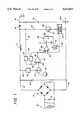
- FIG. 2illustrates a specific example of the circuit of FIG. 1, including values of the components and designations of some components.
- the rectifier bridge 10is not illustrated in FIG. 2 but would, of course, be provided as shown in FIG. 1, and the capacitor 13 may also be provided.
- the UC1842 chip 61contains the oscillator 34, the flip-flop 32 and the comparator 29.
- the chip 61is powered by a separate power supply (such as a 15 volt source) connected to a line 60.
- the line 62has a voltage on it representative of the inductor current through the switch 26 and the parallel resistors 63, thus forming the current sensor 27.
- the chip 61also provides the reference voltage on the line 46 which may be, for example, 5 VDC and which is connected to the summation juncture 44.
- the output of the flip-flopis connected to the switch 26 through a resistor 64 and an IN914 diode 65.
- the switch 26is, for example, an IRFP450 semiconductor switch.
- the block 43(FIG. 1) is formed by two resistors 67 and 68 and a capacitor 69.
- the block 54is formed by a resistor 171 and a capacitor 72.
- the block 52is formed by two resistors 73 and 74 which form a voltage divider between the output terminals 19 and 19A.
- the resistors 67 and 68of course, also form a voltage divider but are across the input lines 14 and 15.
- the error amplifier 47is an LM 358 Op Amp, and the diode 18 is an HFA15TB60.
- the inductor 17has an inductance of, for example, approximately 400 ⁇ H.
- FIGS. 1, 2 and 4show circuits wherein the inductor current is detected by a sensor connected in series with the switch 26. Since the circuit operates only at the peak inductor current, the inductor current may instead be sensed at other locations, as illustrated by the dash-line boxes 27A to 27F in FIG. 6. The current sensing circuit may require more complex arrangements at some locations. For locating 27E and 27F, capacitors 13 and 13A would have to be small and full wave rectification would have to be added to the current signal.
- the circuitemploys a boost topology, operating with a fixed frequency continuous or discontinuous mode.
- the switch 26is operated such that the inductor current follows or tracks the input voltage.
- the output voltageis also sensed and used as an outer control loop.
- the circuitis especially advantageous in that it is relatively simple and in that the sizes of the inductor 17 and the capacitor 21 are relatively small, thereby reducing the overall cost of the system.
- the size of the capacitor 21may be made relatively small because its ripple current is relatively low when the input power factor is nearly 1.0. This capacitance may be reduced and the ripple voltage will be substantially the same as in a standard front end circuit.
- the diode bridge 10may have a reduced current rating because of the near unity power factor.
Landscapes
- Engineering & Computer Science (AREA)
- Power Engineering (AREA)
- Rectifiers (AREA)
Abstract
Description
This is a Continuation of U.S. application Ser. No. 08/405,151, filed Mar. 16, 1995, now abandoned.
This invention relates to a power supply for electrical equipment requiring direct current, the power supply being operable to convert an alternating current line voltage to direct current with an improved input power factor.
Conventional AC to DC converters are well known, which include a full-wave bridge rectifier and a storage capacitor. As is also well known, such a converter causes the line current to become non-sinusoidal, producing an input power factor between 0.6 and 0.7. Due to this relatively poor power factor, the circuit draws substantially more current than would be true if the load were resistive (a power factor of 1.0). A power supply with an input power factor of 0.6 to 0.7 is disadvantageous because it delivers substantially less power at a particular input current than does a power supply with a power factor of close to 1.0.
The foregoing is well known to those skilled in this art, and power supply circuits including power factor correction components have been provided. For example, the following listed U.S. patents relate to such arrangements:
______________________________________ Number Date ______________________________________ 4,074,344 02/14/78 4,677,366 06/30/87 4,777,409 10/11/88 4,801,887 01/31/89 4,816,982 03/28/89 4,831,508 05/16/89 4,940,929 07/10/90 5,003,454 03/26/91 5,181,159 01/19/93 5,301,095 04/05/94 ______________________________________
While the circuits described in the above patents may perform satisfactorily, there is a continuing need for a power supply including an improved power factor correction circuit, which is less complicated and less expensive than those of the prior art.
It is therefore a general object of the present invention to provide an improved power supply including a power factor correction circuit.
A power supply circuit in accordance with this invention converts AC energy from an AC source to DC energy for powering a load, and it comprises first and second circuit lines; full wave rectifier means connectable to the AC source and to said circuit lines for providing a rectified input voltage on said circuit lines; an inductor connected in said first circuit line; an output capacitor connected across said first and second circuit lines between said inductor and the load; a control switch including two power terminals and a control terminal, the two power terminals being connected across said first and second circuit lines between said inductor and said output capacitor; means responsive to current flow through the inductor for providing a current representative signal; a relatively high fixed frequency oscillator means for closing said control switch in each cycle thereof; and means responsive to a comparison of the input plus the output voltages with said current representative signal for opening said control switch when said current representative signal reaches a preset value based on the input plus the output voltages. dr
The invention will be better understood from the following detailed description taken in conjunction with the accompanying drawings, wherein:
FIG. 1 is a block diagram of a circuit embodying the invention;
FIG. 2 is a more detailed schematic diagram of the circuit;
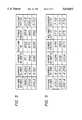
FIG. 3 is a chart listing test results of the circuit of FIG. 2;
FIG. 4 is a schematic diagram similar to FIG. 2 but showing an alternative embodiment of the invention;
FIG. 5 is a chart similar to FIG. 3 but showing test results of the circuit of FIG. 5; and
FIG. 6 is a block diagram similar to FIG. 1 but showing alternative locations of a current sensor.
With reference first to FIG. 1, a full-wave bridge rectifier 10 has its input connected to lines 11 which, in use, are connected, during use, to anAC input 12 such as a 230 volt line. Aninput filter capacitor 13 and/or 13A is connected across the input lines 11 and/or across thebridge output lines
Aninductor 17 and ahigh speed diode 18 are connected in series in theline 14 between thebridge 10 and aDC output terminal 19. The other (return)line 15 is connected to aterminal 19A and to ground. An outputfilter capacitor bank 21 is between theoutput terminals
A current modulator is also provided which senses the full-wave rectified line voltage and forces the input current to be substantially sinusoidal and in phase with the line voltage. The modulator includes asemiconductor switch 26 which is connected in aline 25 between theline 15 and the juncture between theinductor 17 and thediode 18. When theswitch 26 is closed, theinductor 17 current flows through it, and the inductor current is sensed by acircuit 27 connected in series with theswitch 26. As will be described in connection with FIG. 6, the inductor current may be sensed at other locations in the circuit. The voltage output signal of thesensing circuit 27 is connected by aline 28 to the positive (noninverting)input 30 of avoltage comparator 29, the output of which is connected to thereset input 31 of a flip-flop 32. Theset input 33 receives the output of afixed frequency oscillator 34. TheQ output 36 of the flip-flop 32 is connected to thecontrol gate 37 of theswitch 26.
The negative (inverting)input 41 of thecomparator 29 receives a signal representative of the input voltage on theline 14. The full-wave rectified line voltage is monitored by aline 42 which is connected through a resistor-capacitor block 43 to asummation junction 44 that also receives a reference voltage on aline 46. Anerror amplifier 47 has itspositive input 48 connected to receive the sum output of thejunction 44 and has itsoutput 49 connected to theinput 41 of thecomparator 29. The DC output voltage is also monitored by aline 51 connected to theoutput terminal 19, theline 51 being connected through avoltage divider block 52 to thenegative input 53 of theerror amplifier 47. A resistor-capacitor block 54 is connected in a feedback loop between theoutput 49 and theinput 53. The threeblocks
Considering the operation of the circuit, assume that the lines 11 are connected to an ACline voltage supply 12 and that the output terminals 19-19A are connected to a DC load such as an invertor and a variable speed motor. With theswitch 26 open, current flows through thebridge 10, thelines inductor 17 and thediode 18, and charges thecapacitor 21. Theoscillator 34 signal is at a higher frequency (for example, 10 KHz to 100 KHz, but a wider range may also be acceptable) than the power line frequency, and each cycle of theoscillator 34 sets the flip-flop 32 and turns on (closes) theswitch 26. With theswitch 26 closed, theinductor 17 current is shunted through theswitch 26 and thecurrent sensing device 27. Thediode 18 prevents thecapacitor 21 from discharging through theline 25. When the current representative voltage signal on theline 28 exceeds the voltage signal at theinput 41, the output signal of thecomparator 29 switches and resets the flip-flop 32, thereby turning off theswitch 26 and stopping current flow through theline 25. Since theoscillator 34 frequency is much higher than the power line frequency, theswitch 26 may be turned on and off a number of times in each cycle of the line voltage.
The voltage signal on theinput 41 is representative of the input voltage on theline 14. The voltage signal from theline 14 is modified by theblock 43 and summed with the reference voltage on theline 46. The DC output voltage on theline 51 and thesummation 44 voltage are fed to the error amplifier, and the error, or difference, is fed to theinput 41 of thecomparator 29. When the voltage on theinput 30 reaches the voltage on theinput 41, the switch 23 is opened. Thus by modulating the current (by opening and closing the switch 26) by a signal representative of the line voltage, the current waveform is forced to follow the voltage waveform.
FIG. 2 illustrates a specific example of the circuit of FIG. 1, including values of the components and designations of some components. For the components shown in FIG. 2 which have obvious counterparts in FIG. 1, the same reference numerals are used. Therectifier bridge 10 is not illustrated in FIG. 2 but would, of course, be provided as shown in FIG. 1, and thecapacitor 13 may also be provided.
TheUC1842 chip 61 contains theoscillator 34, the flip-flop 32 and thecomparator 29. Thechip 61 is powered by a separate power supply (such as a 15 volt source) connected to aline 60. Theline 62 has a voltage on it representative of the inductor current through theswitch 26 and theparallel resistors 63, thus forming thecurrent sensor 27. Thechip 61 also provides the reference voltage on theline 46 which may be, for example, 5 VDC and which is connected to thesummation juncture 44. The output of the flip-flop is connected to theswitch 26 through aresistor 64 and anIN914 diode 65. Theswitch 26 is, for example, an IRFP450 semiconductor switch.
The block 43 (FIG. 1) is formed by tworesistors capacitor 69. Theblock 54 is formed by a resistor 171 and acapacitor 72. Theblock 52 is formed by tworesistors output terminals resistors
Theerror amplifier 47 is an LM 358 Op Amp, and thediode 18 is an HFA15TB60. Theinductor 17 has an inductance of, for example, approximately 400 μH.
FIG. 3 shows test data for the circuit of FIG. 2, and it will be noted that the power factor is better than 0.952 over a fairly broad range of input voltages.
FIG. 4 shows a circuit similar to that of FIG. 2 but having superior test results as shown by the chart of FIG. 5. Most of the components of the two circuits are the same and therefore the same reference numerals are used. The differences are: theresistor 68 of FIG. 4 is 2K whereas theresistor 68 of FIG. 2 is 20K; theresistor 71 of FIG. 2 is eliminated in the circuit of FIG. 4; and adiode 47A is added in the circuit of FIG. 4 between theerror amplifier 47 and the comparator input of thechip 61. The smaller value of theresistor 74 in FIG. 4 improves the power factor as shown in FIG. 5 (the power factor is greater than 0.970 over a broad range of voltages), and increasing the value of theresistor 71 to infinity improves the voltage regulation of the DC output.
FIGS. 1, 2 and 4 show circuits wherein the inductor current is detected by a sensor connected in series with theswitch 26. Since the circuit operates only at the peak inductor current, the inductor current may instead be sensed at other locations, as illustrated by the dash-line boxes 27A to 27F in FIG. 6. The current sensing circuit may require more complex arrangements at some locations. For locating 27E and 27F,capacitors
Variations and modifications may be made which are encompassed by the scope of the invention and the accompanying claims. For example, in the circuit of FIG. 1, the inputs to thecomparator 29 may be reversed if the inputs to the flip-flop 32 are active low.
It will be apparent from the foregoing that a novel and useful power supply including a power factor correction has been provided. The circuit employs a boost topology, operating with a fixed frequency continuous or discontinuous mode. Theswitch 26 is operated such that the inductor current follows or tracks the input voltage. The output voltage is also sensed and used as an outer control loop. The circuit is especially advantageous in that it is relatively simple and in that the sizes of theinductor 17 and thecapacitor 21 are relatively small, thereby reducing the overall cost of the system. Compared to a standard front end, the size of thecapacitor 21 may be made relatively small because its ripple current is relatively low when the input power factor is nearly 1.0. This capacitance may be reduced and the ripple voltage will be substantially the same as in a standard front end circuit. Thediode bridge 10 may have a reduced current rating because of the near unity power factor.
Claims (12)
1. A power supply and power factor correction circuit comprising first and second circuit lines; rectifier means having an output connected across said circuit lines and an input connectable to an AC source for providing a rectified DC input voltage on said circuit lines; an inductor connected in one of said lines; an output capacitor connected across said lines and a DC output voltage representative signal appearing across said output capacitor, said inductor being between said rectifier and said output capacitor; a control switch including two power terminals and a control terminal, said two power terminals being connected across said power lines between said inductor and said output capacitor; means responsive to current flow through said inductor for providing a current representative signal; oscillator means having a fixed frequency higher than the frequency of the AC source and operatively connected to said control terminal for closing said control switch in each cycle thereof; means responsive to said input voltage for providing an input voltage representative signal, reference means for providing a DC reference voltage. summing means for summing said input voltage representative signal and said reference voltage and forming a summation signal, error means responsive to said summation signal and to said output voltage representative signal for providing an error signal proportional to the difference between said output voltage representative signal and said summation signal, and comparison means responsive to said current representative signal and to said error signal for opening said control switch when said current representative signal reaches a preset value relative to said error signal.
2. A circuit as set forth in claim 1, wherein said current flow responsive means is connected in series with said control switch.
3. A circuit as set forth in claim 1, wherein said current flow responsive means is connected in one of said circuit lines.
4. A circuit as set forth in claim 1, wherein said current flow responsive means is connected in said input of said rectifier means.
5. A circuit as set forth in claim 1, wherein said means responsive to said input voltage is connected to said circuit lines between said rectifier means and said inductor.
6. A circuit as set forth in claim 1, and further comprising a flip-flop including set and reset inputs and an output, said output being connected to said control terminal, said input being connected to said comparison means, and said set input being connected to said oscillator means.
7. A power factor correction circuit comprising first and second circuit lines operable to be connected to an output of a rectifier for providing a rectified DC input voltage on said circuit lines; an inductor connected in one of said lines; an output capacitor connected across said lines and a DC output voltage representative signal appearing across output capacitor, said inductor being between said rectifier and said output capacitor; a control switch including two power terminals and a control terminal, said two power terminals being connected across said power lines between said inductor and said output capacitor; means responsive to current flow through said inductor for providing a current representative signal; oscillator means having a fixed frequency higher than the frequency of the AC source and operatively connected to said control terminal for closing said control switch in each cycle thereof; means responsive to said input voltage for providing an input voltage representative signal, reference means for providing a DC reference voltage, summing means for summing said input voltage representative signal and said reference voltage and forming a summation signal, error means responsive to said summation signal and to said output voltage representative signal for providing an error sisal proportional to the difference between said output voltage representative signal and said summation signal, and comparison means responsive to said current representative signal and to said error signal for opening said control switch when said current representative signal reaches a preset value relative to said error signal.
8. A circuit as set forth in claim 7, wherein said current flow responsive means is connected in series with said control switch.
9. A circuit as set forth in claim 7, wherein said current flow responsive means is connected in one of said circuit lines.
10. A circuit as set forth in claim 7, wherein said means responsive to said input voltage is connected to said circuit lines.
11. A circuit as set forth in claim 7, and further comprising a flip-flop including set and reset inputs and an output, said output being connected to said control terminal, said reset input being connected to said comparison means, and said set input being connected to said oscillator means.
12. A power supply and power factor correction circuit, comprising first and second circuit lines; a full wave rectifier connected to said circuit lines for forming a rectified input voltage on said circuit lines; an inductor connected in said first circuit line; an output capacitor connected across said circuit lines, said inductor being between said output capacitor and said rectifier; a control switch including two power terminals and a control terminal, said power terminals being connected across said lines between said inducter and said output capacitor; current means responsive to current through said inducter for providing an inductor current representative signal; a flip-flop having an output connected to said control terminal and having set and reset inputs; a fixed frequency oscillator connected to said set input; a comparator having first and second comparator inputs and an output connected to said reset input; and voltage means responsive to an error between said input voltage and a reference voltage and to an output voltage on said output capacitor for providing a voltage representative signal, said voltage representative signal being connected to said first comparator input; said second comparator input being connected to receive said inductor current representative signal; said comparator forming a comparison signal which resets said flip-flop when said inductor current representative signal reaches said voltage representative signal at substantially the peak of said inductor current representative signal.
Priority Applications (1)
| Application Number | Priority Date | Filing Date | Title |
|---|---|---|---|
| US08/661,453US5614812A (en) | 1995-03-16 | 1996-06-11 | Power supply with power factor correction |
Applications Claiming Priority (2)
| Application Number | Priority Date | Filing Date | Title |
|---|---|---|---|
| US40515195A | 1995-03-16 | 1995-03-16 | |
| US08/661,453US5614812A (en) | 1995-03-16 | 1996-06-11 | Power supply with power factor correction |
Related Parent Applications (1)
| Application Number | Title | Priority Date | Filing Date |
|---|---|---|---|
| US40515195AContinuation | 1995-03-16 | 1995-03-16 |
Publications (1)
| Publication Number | Publication Date |
|---|---|
| US5614812Atrue US5614812A (en) | 1997-03-25 |
Family
ID=23602495
Family Applications (1)
| Application Number | Title | Priority Date | Filing Date |
|---|---|---|---|
| US08/661,453Expired - Fee RelatedUS5614812A (en) | 1995-03-16 | 1996-06-11 | Power supply with power factor correction |
Country Status (4)
| Country | Link |
|---|---|
| US (1) | US5614812A (en) |
| EP (1) | EP0732797B1 (en) |
| DE (1) | DE69525441T2 (en) |
| DK (1) | DK0732797T3 (en) |
Cited By (36)
| Publication number | Priority date | Publication date | Assignee | Title |
|---|---|---|---|---|
| WO1999000888A1 (en)* | 1997-06-30 | 1999-01-07 | Motorola Inc. | Leakage current power supply |
| US5949275A (en)* | 1997-05-02 | 1999-09-07 | Delco Electronics Corp. | Dual output voltage boost circuit |
| US5995395A (en)* | 1996-03-29 | 1999-11-30 | Sgs-Thomson Microelectronics S.A. | Control of a composite bridge at zero voltage |
| US6150771A (en) | 1997-06-11 | 2000-11-21 | Precision Solar Controls Inc. | Circuit for interfacing between a conventional traffic signal conflict monitor and light emitting diodes replacing a conventional incandescent bulb in the signal |
| US6262565B1 (en) | 1999-05-07 | 2001-07-17 | Mytech Corporation | Electrical load switch |
| US6377034B1 (en)* | 2000-12-11 | 2002-04-23 | Texas Instruments Incorporated | Method and circuits for inductor current measurement in MOS switching regulators |
| US6487098B2 (en) | 2001-02-01 | 2002-11-26 | International Business Machines Corporation | Power factor correction (PFC) circuit that eliminates an inrush current limit circuit |
| US6686725B1 (en)* | 2002-11-12 | 2004-02-03 | Samsung Electro-Mechanics Co., Ltd. | Power supply circuit compensating power factor |
| US20050123408A1 (en)* | 2003-12-08 | 2005-06-09 | Koehl Robert M. | Pump control system and method |
| US20060204367A1 (en)* | 2001-11-26 | 2006-09-14 | Meza Humberto V | Pump and pump control circuit apparatus and method |
| US20070103947A1 (en)* | 2005-11-04 | 2007-05-10 | Yasutaka Taguchi | Power source apparatus |
| US20070114162A1 (en)* | 2004-08-26 | 2007-05-24 | Pentair Water Pool And Spa, Inc. | Control algorithm of variable speed pumping system |
| US20070154319A1 (en)* | 2004-08-26 | 2007-07-05 | Stiles Robert W Jr | Pumping system with power optimization |
| US20070154322A1 (en)* | 2004-08-26 | 2007-07-05 | Stiles Robert W Jr | Pumping system with two way communication |
| US20070154321A1 (en)* | 2004-08-26 | 2007-07-05 | Stiles Robert W Jr | Priming protection |
| US20070154320A1 (en)* | 2004-08-26 | 2007-07-05 | Pentair Water Pool And Spa, Inc. | Flow control |
| US20070163929A1 (en)* | 2004-08-26 | 2007-07-19 | Pentair Water Pool And Spa, Inc. | Filter loading |
| US20070183902A1 (en)* | 2004-08-26 | 2007-08-09 | Pentair Water Pool And Spa, Inc. | Anti-entrapment and anti-dead head function |
| US20080130336A1 (en)* | 2005-07-01 | 2008-06-05 | Yasutaka Taguchi | Power Supply Device |
| US20080205103A1 (en)* | 2004-09-24 | 2008-08-28 | Sehat Sutardja | Power factor control systems and methods |
| US20080239766A1 (en)* | 2005-08-29 | 2008-10-02 | Austriamicrosystems Ag | Control System for a Voltage Converter and Method |
| US20100310382A1 (en)* | 2009-06-09 | 2010-12-09 | Melissa Drechsel Kidd | Method of Controlling a Pump and Motor |
| US7874808B2 (en) | 2004-08-26 | 2011-01-25 | Pentair Water Pool And Spa, Inc. | Variable speed pumping system and method |
| USRE42161E1 (en) | 1996-06-27 | 2011-02-22 | Relume Corporation | Power supply for light emitting diode array |
| US20110211377A1 (en)* | 2008-11-25 | 2011-09-01 | Murata Manufacturing Co., Ltd. | Power factor correction converter |
| US8436559B2 (en) | 2009-06-09 | 2013-05-07 | Sta-Rite Industries, Llc | System and method for motor drive control pad and drive terminals |
| US8564233B2 (en) | 2009-06-09 | 2013-10-22 | Sta-Rite Industries, Llc | Safety system and method for pump and motor |
| US8602743B2 (en) | 2008-10-06 | 2013-12-10 | Pentair Water Pool And Spa, Inc. | Method of operating a safety vacuum release system |
| TWI470915B (en)* | 2008-03-21 | 2015-01-21 | Marvell World Trade Ltd | Boost converter and power factor controller |
| US9000736B2 (en) | 2013-05-03 | 2015-04-07 | Cooper Technologies Company | Power factor correction algorithm for arbitrary input waveform |
| US9190901B2 (en) | 2013-05-03 | 2015-11-17 | Cooper Technologies Company | Bridgeless boost power factor correction circuit for constant current input |
| US9214855B2 (en) | 2013-05-03 | 2015-12-15 | Cooper Technologies Company | Active power factor correction circuit for a constant current power converter |
| US9548794B2 (en) | 2013-05-03 | 2017-01-17 | Cooper Technologies Company | Power factor correction for constant current input with power line communication |
| US9568005B2 (en) | 2010-12-08 | 2017-02-14 | Pentair Water Pool And Spa, Inc. | Discharge vacuum relief valve for safety vacuum release system |
| US9885360B2 (en) | 2012-10-25 | 2018-02-06 | Pentair Flow Technologies, Llc | Battery backup sump pump systems and methods |
| US10465676B2 (en) | 2011-11-01 | 2019-11-05 | Pentair Water Pool And Spa, Inc. | Flow locking system and method |
Families Citing this family (2)
| Publication number | Priority date | Publication date | Assignee | Title |
|---|---|---|---|---|
| DE19854567A1 (en)* | 1998-11-26 | 2000-06-08 | Danfoss Compressors Gmbh | Method of controlling a rectifier circuit and rectifier circuit |
| CN103560662B (en)* | 2013-10-31 | 2016-04-06 | 广州金升阳科技有限公司 | A kind of PFC control method and control device |
Citations (10)
| Publication number | Priority date | Publication date | Assignee | Title |
|---|---|---|---|---|
| US4719552A (en)* | 1985-11-22 | 1988-01-12 | U.S. Philips Corporation | AC-DC converter triggered by variable frequency pulses |
| US5003454A (en)* | 1990-01-09 | 1991-03-26 | North American Philips Corporation | Power supply with improved power factor correction |
| EP0431778A1 (en)* | 1989-11-20 | 1991-06-12 | General Electric Company | AC to DC power conversion circuit with low harmonic distorsion |
| US5047912A (en)* | 1990-03-09 | 1991-09-10 | International Rectifier Corporation | Four-terminal unity power factor electronic rectifier |
| US5146398A (en)* | 1991-08-20 | 1992-09-08 | Led Corporation N.V. | Power factor correction device provided with a frequency and amplitude modulated boost converter |
| EP0516122A2 (en)* | 1991-05-31 | 1992-12-02 | Kabushiki Kaisha Toshiba | Inverter power supply |
| EP0580237A1 (en)* | 1992-07-20 | 1994-01-26 | N.V. Nederlandsche Apparatenfabriek NEDAP | Power factor correction circuit |
| US5349284A (en)* | 1991-02-27 | 1994-09-20 | Astec International, Ltd. | Power factor boost converter power supply |
| US5367247A (en)* | 1992-08-10 | 1994-11-22 | International Business Machines Corporation | Critically continuous boost converter |
| US5436550A (en)* | 1993-01-22 | 1995-07-25 | Tokyo, Inc. | AC-DC converter having saw-tooth wave generating circuit in active filter |
Family Cites Families (9)
| Publication number | Priority date | Publication date | Assignee | Title |
|---|---|---|---|---|
| US4074344A (en) | 1975-09-22 | 1978-02-14 | Gte Sylvania Incorporated | High power factor ac to dc converter circuit |
| US4777409A (en) | 1984-03-23 | 1988-10-11 | Tracy Stanley J | Fluorescent lamp energizing circuit |
| DE3612147A1 (en) | 1986-04-10 | 1987-10-15 | Philips Patentverwaltung | CIRCUIT ARRANGEMENT FOR GENERATING A DC VOLTAGE FROM A SINUS-SHAPED INPUT VOLTAGE |
| US4677366A (en) | 1986-05-12 | 1987-06-30 | Pioneer Research, Inc. | Unity power factor power supply |
| US4831508A (en) | 1987-10-20 | 1989-05-16 | Computer Products Inc. | Power supply system having improved input power factor |
| US4816982A (en) | 1987-11-23 | 1989-03-28 | Viteq Corporation | AC to DC power converter with integrated line current control for improving power factor |
| US4940929A (en) | 1989-06-23 | 1990-07-10 | Apollo Computer, Inc. | AC to DC converter with unity power factor |
| US5181159A (en) | 1990-12-24 | 1993-01-19 | General Electric Company | AC to DC converter having an enhanced power factor |
| US5301095A (en) | 1991-10-01 | 1994-04-05 | Origin Electric Company, Limited | High power factor AC/DC converter |
- 1995
- 1995-10-02DKDK95306967Tpatent/DK0732797T3/enactive
- 1995-10-02EPEP95306967Apatent/EP0732797B1/ennot_activeExpired - Lifetime
- 1995-10-02DEDE69525441Tpatent/DE69525441T2/ennot_activeExpired - Fee Related
- 1996
- 1996-06-11USUS08/661,453patent/US5614812A/ennot_activeExpired - Fee Related
Patent Citations (10)
| Publication number | Priority date | Publication date | Assignee | Title |
|---|---|---|---|---|
| US4719552A (en)* | 1985-11-22 | 1988-01-12 | U.S. Philips Corporation | AC-DC converter triggered by variable frequency pulses |
| EP0431778A1 (en)* | 1989-11-20 | 1991-06-12 | General Electric Company | AC to DC power conversion circuit with low harmonic distorsion |
| US5003454A (en)* | 1990-01-09 | 1991-03-26 | North American Philips Corporation | Power supply with improved power factor correction |
| US5047912A (en)* | 1990-03-09 | 1991-09-10 | International Rectifier Corporation | Four-terminal unity power factor electronic rectifier |
| US5349284A (en)* | 1991-02-27 | 1994-09-20 | Astec International, Ltd. | Power factor boost converter power supply |
| EP0516122A2 (en)* | 1991-05-31 | 1992-12-02 | Kabushiki Kaisha Toshiba | Inverter power supply |
| US5146398A (en)* | 1991-08-20 | 1992-09-08 | Led Corporation N.V. | Power factor correction device provided with a frequency and amplitude modulated boost converter |
| EP0580237A1 (en)* | 1992-07-20 | 1994-01-26 | N.V. Nederlandsche Apparatenfabriek NEDAP | Power factor correction circuit |
| US5367247A (en)* | 1992-08-10 | 1994-11-22 | International Business Machines Corporation | Critically continuous boost converter |
| US5436550A (en)* | 1993-01-22 | 1995-07-25 | Tokyo, Inc. | AC-DC converter having saw-tooth wave generating circuit in active filter |
Cited By (127)
| Publication number | Priority date | Publication date | Assignee | Title |
|---|---|---|---|---|
| US5995395A (en)* | 1996-03-29 | 1999-11-30 | Sgs-Thomson Microelectronics S.A. | Control of a composite bridge at zero voltage |
| USRE42161E1 (en) | 1996-06-27 | 2011-02-22 | Relume Corporation | Power supply for light emitting diode array |
| US5949275A (en)* | 1997-05-02 | 1999-09-07 | Delco Electronics Corp. | Dual output voltage boost circuit |
| US6150771A (en) | 1997-06-11 | 2000-11-21 | Precision Solar Controls Inc. | Circuit for interfacing between a conventional traffic signal conflict monitor and light emitting diodes replacing a conventional incandescent bulb in the signal |
| US5909365A (en)* | 1997-06-30 | 1999-06-01 | Motorola Inc. | Leakage current power supply |
| WO1999000888A1 (en)* | 1997-06-30 | 1999-01-07 | Motorola Inc. | Leakage current power supply |
| US6262565B1 (en) | 1999-05-07 | 2001-07-17 | Mytech Corporation | Electrical load switch |
| US6377034B1 (en)* | 2000-12-11 | 2002-04-23 | Texas Instruments Incorporated | Method and circuits for inductor current measurement in MOS switching regulators |
| US6487098B2 (en) | 2001-02-01 | 2002-11-26 | International Business Machines Corporation | Power factor correction (PFC) circuit that eliminates an inrush current limit circuit |
| US20080181788A1 (en)* | 2001-11-26 | 2008-07-31 | Meza Humberto V | Pump and pump control circuit apparatus and method |
| US9109590B2 (en) | 2001-11-26 | 2015-08-18 | Shurflo, Llc | Pump and pump control circuit apparatus and method |
| US20060204367A1 (en)* | 2001-11-26 | 2006-09-14 | Meza Humberto V | Pump and pump control circuit apparatus and method |
| US8317485B2 (en) | 2001-11-26 | 2012-11-27 | Shurflo, Llc | Pump and pump control circuit apparatus and method |
| US8337166B2 (en) | 2001-11-26 | 2012-12-25 | Shurflo, Llc | Pump and pump control circuit apparatus and method |
| US8641383B2 (en) | 2001-11-26 | 2014-02-04 | Shurflo, Llc | Pump and pump control circuit apparatus and method |
| US20080181786A1 (en)* | 2001-11-26 | 2008-07-31 | Meza Humberto V | Pump and pump control circuit apparatus and method |
| US20080181790A1 (en)* | 2001-11-26 | 2008-07-31 | Meza Humberto V | Pump and pump control circuit apparatus and method |
| US20080152508A1 (en)* | 2001-11-26 | 2008-06-26 | Meza Humberto V | Pump and pump control circuit apparatus and method |
| US7878766B2 (en) | 2001-11-26 | 2011-02-01 | Shurflo, Llc | Pump and pump control circuit apparatus and method |
| US6686725B1 (en)* | 2002-11-12 | 2004-02-03 | Samsung Electro-Mechanics Co., Ltd. | Power supply circuit compensating power factor |
| US20080131289A1 (en)* | 2003-12-08 | 2008-06-05 | Koehl Robert M | Pump controller system and method |
| US20080260540A1 (en)* | 2003-12-08 | 2008-10-23 | Koehl Robert M | Pump controller system and method |
| US20080131291A1 (en)* | 2003-12-08 | 2008-06-05 | Koehl Robert M | Pump controller system and method |
| US20080131295A1 (en)* | 2003-12-08 | 2008-06-05 | Koehl Robert M | Pump controller system and method |
| US9328727B2 (en) | 2003-12-08 | 2016-05-03 | Pentair Water Pool And Spa, Inc. | Pump controller system and method |
| US20080131296A1 (en)* | 2003-12-08 | 2008-06-05 | Koehl Robert M | Pump controller system and method |
| US20080140353A1 (en)* | 2003-12-08 | 2008-06-12 | Koehl Robert M | Pump controller system and method |
| US9371829B2 (en) | 2003-12-08 | 2016-06-21 | Pentair Water Pool And Spa, Inc. | Pump controller system and method |
| US20080181787A1 (en)* | 2003-12-08 | 2008-07-31 | Koehl Robert M | Pump controller system and method |
| US9399992B2 (en) | 2003-12-08 | 2016-07-26 | Pentair Water Pool And Spa, Inc. | Pump controller system and method |
| US10241524B2 (en) | 2003-12-08 | 2019-03-26 | Pentair Water Pool And Spa, Inc. | Pump controller system and method |
| US10289129B2 (en) | 2003-12-08 | 2019-05-14 | Pentair Water Pool And Spa, Inc. | Pump controller system and method |
| US20080181789A1 (en)* | 2003-12-08 | 2008-07-31 | Koehl Robert M | Pump controller system and method |
| US8641385B2 (en) | 2003-12-08 | 2014-02-04 | Sta-Rite Industries, Llc | Pump controller system and method |
| US8540493B2 (en) | 2003-12-08 | 2013-09-24 | Sta-Rite Industries, Llc | Pump control system and method |
| US20080131286A1 (en)* | 2003-12-08 | 2008-06-05 | Koehl Robert M | Pump controller system and method |
| US7572108B2 (en) | 2003-12-08 | 2009-08-11 | Sta-Rite Industries, Llc | Pump controller system and method |
| US8444394B2 (en) | 2003-12-08 | 2013-05-21 | Sta-Rite Industries, Llc | Pump controller system and method |
| US7612510B2 (en) | 2003-12-08 | 2009-11-03 | Sta-Rite Industries, Llc | Pump controller system and method |
| US10409299B2 (en) | 2003-12-08 | 2019-09-10 | Pentair Water Pool And Spa, Inc. | Pump controller system and method |
| US7686587B2 (en) | 2003-12-08 | 2010-03-30 | Sta-Rite Industries, Llc | Pump controller system and method |
| US7704051B2 (en) | 2003-12-08 | 2010-04-27 | Sta-Rite Industries, Llc | Pump controller system and method |
| US10416690B2 (en) | 2003-12-08 | 2019-09-17 | Pentair Water Pool And Spa, Inc. | Pump controller system and method |
| US10642287B2 (en) | 2003-12-08 | 2020-05-05 | Pentair Water Pool And Spa, Inc. | Pump controller system and method |
| US7751159B2 (en) | 2003-12-08 | 2010-07-06 | Sta-Rite Industries, Llc | Pump controller system and method |
| US7990091B2 (en) | 2003-12-08 | 2011-08-02 | Sta-Rite Industries, Llc | Pump controller system and method |
| US7815420B2 (en) | 2003-12-08 | 2010-10-19 | Sta-Rite Industries, Llc | Pump controller system and method |
| US7983877B2 (en) | 2003-12-08 | 2011-07-19 | Sta-Rite Industries, Llc | Pump controller system and method |
| US7976284B2 (en) | 2003-12-08 | 2011-07-12 | Sta-Rite Industries, Llc | Pump controller system and method |
| US20050123408A1 (en)* | 2003-12-08 | 2005-06-09 | Koehl Robert M. | Pump control system and method |
| US7857600B2 (en) | 2003-12-08 | 2010-12-28 | Sta-Rite Industries, Llc | Pump controller system and method |
| US8043070B2 (en) | 2004-08-26 | 2011-10-25 | Pentair Water Pool And Spa, Inc. | Speed control |
| US10240606B2 (en) | 2004-08-26 | 2019-03-26 | Pentair Water Pool And Spa, Inc. | Pumping system with two way communication |
| US11391281B2 (en) | 2004-08-26 | 2022-07-19 | Pentair Water Pool And Spa, Inc. | Priming protection |
| US7854597B2 (en) | 2004-08-26 | 2010-12-21 | Pentair Water Pool And Spa, Inc. | Pumping system with two way communication |
| US20110052416A1 (en)* | 2004-08-26 | 2011-03-03 | Robert Stiles | Variable Speed Pumping System and Method |
| US20110076156A1 (en)* | 2004-08-26 | 2011-03-31 | Stiles Jr Robert W | Flow Control |
| US20110091329A1 (en)* | 2004-08-26 | 2011-04-21 | Stiles Jr Robert W | Pumping System with Two Way Communication |
| US11073155B2 (en) | 2004-08-26 | 2021-07-27 | Pentair Water Pool And Spa, Inc. | Pumping system with power optimization |
| US7845913B2 (en) | 2004-08-26 | 2010-12-07 | Pentair Water Pool And Spa, Inc. | Flow control |
| US10947981B2 (en) | 2004-08-26 | 2021-03-16 | Pentair Water Pool And Spa, Inc. | Variable speed pumping system and method |
| US10871001B2 (en) | 2004-08-26 | 2020-12-22 | Pentair Water Pool And Spa, Inc. | Filter loading |
| US8019479B2 (en) | 2004-08-26 | 2011-09-13 | Pentair Water Pool And Spa, Inc. | Control algorithm of variable speed pumping system |
| US10871163B2 (en) | 2004-08-26 | 2020-12-22 | Pentair Water Pool And Spa, Inc. | Pumping system and method having an independent controller |
| US10731655B2 (en) | 2004-08-26 | 2020-08-04 | Pentair Water Pool And Spa, Inc. | Priming protection |
| US10527042B2 (en) | 2004-08-26 | 2020-01-07 | Pentair Water Pool And Spa, Inc. | Speed control |
| US10502203B2 (en) | 2004-08-26 | 2019-12-10 | Pentair Water Pool And Spa, Inc. | Speed control |
| US7686589B2 (en) | 2004-08-26 | 2010-03-30 | Pentair Water Pool And Spa, Inc. | Pumping system with power optimization |
| US10480516B2 (en) | 2004-08-26 | 2019-11-19 | Pentair Water Pool And Spa, Inc. | Anti-entrapment and anti-deadhead function |
| US10415569B2 (en) | 2004-08-26 | 2019-09-17 | Pentair Water Pool And Spa, Inc. | Flow control |
| US8465262B2 (en) | 2004-08-26 | 2013-06-18 | Pentair Water Pool And Spa, Inc. | Speed control |
| US8469675B2 (en) | 2004-08-26 | 2013-06-25 | Pentair Water Pool And Spa, Inc. | Priming protection |
| US8480373B2 (en) | 2004-08-26 | 2013-07-09 | Pentair Water Pool And Spa, Inc. | Filter loading |
| US8500413B2 (en) | 2004-08-26 | 2013-08-06 | Pentair Water Pool And Spa, Inc. | Pumping system with power optimization |
| US20070114162A1 (en)* | 2004-08-26 | 2007-05-24 | Pentair Water Pool And Spa, Inc. | Control algorithm of variable speed pumping system |
| US20070154319A1 (en)* | 2004-08-26 | 2007-07-05 | Stiles Robert W Jr | Pumping system with power optimization |
| US8573952B2 (en) | 2004-08-26 | 2013-11-05 | Pentair Water Pool And Spa, Inc. | Priming protection |
| US20070154322A1 (en)* | 2004-08-26 | 2007-07-05 | Stiles Robert W Jr | Pumping system with two way communication |
| US8602745B2 (en) | 2004-08-26 | 2013-12-10 | Pentair Water Pool And Spa, Inc. | Anti-entrapment and anti-dead head function |
| US10240604B2 (en) | 2004-08-26 | 2019-03-26 | Pentair Water Pool And Spa, Inc. | Pumping system with housing and user interface |
| US7874808B2 (en) | 2004-08-26 | 2011-01-25 | Pentair Water Pool And Spa, Inc. | Variable speed pumping system and method |
| US20070154321A1 (en)* | 2004-08-26 | 2007-07-05 | Stiles Robert W Jr | Priming protection |
| US8801389B2 (en) | 2004-08-26 | 2014-08-12 | Pentair Water Pool And Spa, Inc. | Flow control |
| US8840376B2 (en) | 2004-08-26 | 2014-09-23 | Pentair Water Pool And Spa, Inc. | Pumping system with power optimization |
| US9932984B2 (en) | 2004-08-26 | 2018-04-03 | Pentair Water Pool And Spa, Inc. | Pumping system with power optimization |
| US9777733B2 (en) | 2004-08-26 | 2017-10-03 | Pentair Water Pool And Spa, Inc. | Flow control |
| US9051930B2 (en) | 2004-08-26 | 2015-06-09 | Pentair Water Pool And Spa, Inc. | Speed control |
| US20070183902A1 (en)* | 2004-08-26 | 2007-08-09 | Pentair Water Pool And Spa, Inc. | Anti-entrapment and anti-dead head function |
| US9605680B2 (en) | 2004-08-26 | 2017-03-28 | Pentair Water Pool And Spa, Inc. | Control algorithm of variable speed pumping system |
| US9551344B2 (en) | 2004-08-26 | 2017-01-24 | Pentair Water Pool And Spa, Inc. | Anti-entrapment and anti-dead head function |
| US20070163929A1 (en)* | 2004-08-26 | 2007-07-19 | Pentair Water Pool And Spa, Inc. | Filter loading |
| US20070154320A1 (en)* | 2004-08-26 | 2007-07-05 | Pentair Water Pool And Spa, Inc. | Flow control |
| US20070154323A1 (en)* | 2004-08-26 | 2007-07-05 | Stiles Robert W Jr | Speed control |
| US9404500B2 (en) | 2004-08-26 | 2016-08-02 | Pentair Water Pool And Spa, Inc. | Control algorithm of variable speed pumping system |
| US20080205103A1 (en)* | 2004-09-24 | 2008-08-28 | Sehat Sutardja | Power factor control systems and methods |
| US20110026284A1 (en)* | 2004-09-24 | 2011-02-03 | Sehat Sutardja | Power Factor Control Systems and Methods |
| US7812576B2 (en)* | 2004-09-24 | 2010-10-12 | Marvell World Trade Ltd. | Power factor control systems and methods |
| US8111050B2 (en) | 2004-09-24 | 2012-02-07 | Marvell World Trade Ltd. | Power factor control systems and methods |
| US9455644B2 (en) | 2004-09-24 | 2016-09-27 | Marvell International Ltd. | Method and apparatus for changing a frequency of a switch prior to a level of current received from an inductor decreasing to a predetermined level |
| US8680822B2 (en) | 2004-09-24 | 2014-03-25 | Marvell World Trade Ltd. | Power factor control systems and methods |
| US7723964B2 (en)* | 2004-12-15 | 2010-05-25 | Fujitsu General Limited | Power supply device |
| US20080130336A1 (en)* | 2005-07-01 | 2008-06-05 | Yasutaka Taguchi | Power Supply Device |
| US20080239766A1 (en)* | 2005-08-29 | 2008-10-02 | Austriamicrosystems Ag | Control System for a Voltage Converter and Method |
| US7738265B2 (en)* | 2005-08-29 | 2010-06-15 | Austriamicrosystems Ag | Control system for a voltage converter and method |
| US7580272B2 (en)* | 2005-11-04 | 2009-08-25 | Fujitsu General Limited | Power source apparatus |
| US20070103947A1 (en)* | 2005-11-04 | 2007-05-10 | Yasutaka Taguchi | Power source apparatus |
| TWI470915B (en)* | 2008-03-21 | 2015-01-21 | Marvell World Trade Ltd | Boost converter and power factor controller |
| US10724263B2 (en) | 2008-10-06 | 2020-07-28 | Pentair Water Pool And Spa, Inc. | Safety vacuum release system |
| US9726184B2 (en) | 2008-10-06 | 2017-08-08 | Pentair Water Pool And Spa, Inc. | Safety vacuum release system |
| US8602743B2 (en) | 2008-10-06 | 2013-12-10 | Pentair Water Pool And Spa, Inc. | Method of operating a safety vacuum release system |
| US20110211377A1 (en)* | 2008-11-25 | 2011-09-01 | Murata Manufacturing Co., Ltd. | Power factor correction converter |
| US8228696B2 (en)* | 2008-11-25 | 2012-07-24 | Murata Manufacturing Co., Ltd. | Power factor correction converter |
| US9556874B2 (en) | 2009-06-09 | 2017-01-31 | Pentair Flow Technologies, Llc | Method of controlling a pump and motor |
| US8436559B2 (en) | 2009-06-09 | 2013-05-07 | Sta-Rite Industries, Llc | System and method for motor drive control pad and drive terminals |
| US11493034B2 (en) | 2009-06-09 | 2022-11-08 | Pentair Flow Technologies, Llc | Method of controlling a pump and motor |
| US20100310382A1 (en)* | 2009-06-09 | 2010-12-09 | Melissa Drechsel Kidd | Method of Controlling a Pump and Motor |
| US10590926B2 (en) | 2009-06-09 | 2020-03-17 | Pentair Flow Technologies, Llc | Method of controlling a pump and motor |
| US9712098B2 (en) | 2009-06-09 | 2017-07-18 | Pentair Flow Technologies, Llc | Safety system and method for pump and motor |
| US8564233B2 (en) | 2009-06-09 | 2013-10-22 | Sta-Rite Industries, Llc | Safety system and method for pump and motor |
| US9568005B2 (en) | 2010-12-08 | 2017-02-14 | Pentair Water Pool And Spa, Inc. | Discharge vacuum relief valve for safety vacuum release system |
| US10883489B2 (en) | 2011-11-01 | 2021-01-05 | Pentair Water Pool And Spa, Inc. | Flow locking system and method |
| US10465676B2 (en) | 2011-11-01 | 2019-11-05 | Pentair Water Pool And Spa, Inc. | Flow locking system and method |
| US9885360B2 (en) | 2012-10-25 | 2018-02-06 | Pentair Flow Technologies, Llc | Battery backup sump pump systems and methods |
| US9190901B2 (en) | 2013-05-03 | 2015-11-17 | Cooper Technologies Company | Bridgeless boost power factor correction circuit for constant current input |
| US9214855B2 (en) | 2013-05-03 | 2015-12-15 | Cooper Technologies Company | Active power factor correction circuit for a constant current power converter |
| US9000736B2 (en) | 2013-05-03 | 2015-04-07 | Cooper Technologies Company | Power factor correction algorithm for arbitrary input waveform |
| US9548794B2 (en) | 2013-05-03 | 2017-01-17 | Cooper Technologies Company | Power factor correction for constant current input with power line communication |
Also Published As
| Publication number | Publication date |
|---|---|
| EP0732797A1 (en) | 1996-09-18 |
| DE69525441T2 (en) | 2002-07-11 |
| DE69525441D1 (en) | 2002-03-21 |
| DK0732797T3 (en) | 2002-03-18 |
| EP0732797B1 (en) | 2002-02-13 |
Similar Documents
| Publication | Publication Date | Title |
|---|---|---|
| US5614812A (en) | Power supply with power factor correction | |
| US5144222A (en) | Apparatus for controlling the input impedance of a power converter | |
| US5146398A (en) | Power factor correction device provided with a frequency and amplitude modulated boost converter | |
| EP0199903B1 (en) | A control apparatus for rectifying circuits | |
| US5003454A (en) | Power supply with improved power factor correction | |
| EP1261119A2 (en) | Power factor corrector with efficient ripple attenuator | |
| JP2675509B2 (en) | Power factor correction circuit | |
| WO1989011691A1 (en) | Ac to dc power converter with input current waveform control | |
| CA2114507A1 (en) | Bimodal fast transfer off-line uninterruptible power supply | |
| US5072355A (en) | Ac-dc chopper converter type of supply | |
| US6037754A (en) | SMPS with input voltage sensing via boost inductor current sensing | |
| JPH11136942A (en) | Switching power source | |
| JP2995962B2 (en) | Power supply circuit for constant voltage power supply | |
| JP3082849B2 (en) | Uninterruptible power system | |
| JP2612220B2 (en) | Rectifier power supply | |
| JP2646824B2 (en) | Power supply | |
| Srinivasan et al. | A single phase two-switch buck type AC-DC converter topology with inductor voltage control | |
| JPH0336209Y2 (en) | ||
| JP2515403Y2 (en) | Switching power supply | |
| JPH0522944A (en) | Forward converter | |
| JPH04200274A (en) | Single-phase rectifying circuit | |
| JPH0756636Y2 (en) | Switching power supply | |
| JPH0570389B2 (en) | ||
| JPH0670547A (en) | Improving equipment for input power factor of power conversion device | |
| JPH01321871A (en) | Output waveform control circuit for no-break power unit |
Legal Events
| Date | Code | Title | Description |
|---|---|---|---|
| FPAY | Fee payment | Year of fee payment:4 | |
| REMI | Maintenance fee reminder mailed | ||
| LAPS | Lapse for failure to pay maintenance fees | ||
| STCH | Information on status: patent discontinuation | Free format text:PATENT EXPIRED DUE TO NONPAYMENT OF MAINTENANCE FEES UNDER 37 CFR 1.362 | |
| FP | Lapsed due to failure to pay maintenance fee | Effective date:20050325 |