US5613557A - Apparatus and method for sealing perforated well casing - Google Patents
Apparatus and method for sealing perforated well casingDownload PDFInfo
- Publication number
- US5613557A US5613557AUS08/448,108US44810895AUS5613557AUS 5613557 AUS5613557 AUS 5613557AUS 44810895 AUS44810895 AUS 44810895AUS 5613557 AUS5613557 AUS 5613557A
- Authority
- US
- United States
- Prior art keywords
- sleeve
- conduit
- opening
- engagement
- forcible
- Prior art date
- Legal status (The legal status is an assumption and is not a legal conclusion. Google has not performed a legal analysis and makes no representation as to the accuracy of the status listed.)
- Expired - Lifetime
Links
- 238000007789sealingMethods0.000titleclaimsdescription28
- 238000000034methodMethods0.000titleclaimsdescription27
- 239000012530fluidSubstances0.000claimsabstractdescription68
- 239000002360explosiveSubstances0.000claimsabstractdescription48
- 230000015572biosynthetic processEffects0.000claimsabstractdescription14
- 239000000463materialSubstances0.000claimsdescription64
- 239000004020conductorSubstances0.000claimsdescription14
- 229910052751metalInorganic materials0.000claimsdescription14
- 239000002184metalSubstances0.000claimsdescription14
- 239000011248coating agentSubstances0.000claimsdescription9
- 238000000576coating methodMethods0.000claimsdescription9
- 238000007373indentationMethods0.000claimsdescription7
- 239000007788liquidSubstances0.000claimsdescription6
- 230000000694effectsEffects0.000claimsdescription5
- 238000006073displacement reactionMethods0.000claimsdescription4
- 230000004044responseEffects0.000claimsdescription2
- 238000004880explosionMethods0.000claims4
- 238000004519manufacturing processMethods0.000abstractdescription8
- 238000002347injectionMethods0.000abstractdescription2
- 239000007924injectionSubstances0.000abstractdescription2
- 239000010410layerSubstances0.000description20
- 239000000853adhesiveSubstances0.000description14
- 230000001070adhesive effectEffects0.000description14
- 230000000903blocking effectEffects0.000description12
- 239000000565sealantSubstances0.000description9
- 239000003832thermiteSubstances0.000description9
- 238000004891communicationMethods0.000description8
- 238000005474detonationMethods0.000description4
- 230000004048modificationEffects0.000description4
- 238000012986modificationMethods0.000description4
- 239000004033plasticSubstances0.000description4
- 229920003023plasticPolymers0.000description4
- 230000000977initiatory effectEffects0.000description3
- 238000009434installationMethods0.000description3
- 239000000203mixtureSubstances0.000description3
- 239000000758substrateSubstances0.000description3
- XEEYBQQBJWHFJM-UHFFFAOYSA-NIronChemical compound[Fe]XEEYBQQBJWHFJM-UHFFFAOYSA-N0.000description2
- 238000010521absorption reactionMethods0.000description2
- 230000008901benefitEffects0.000description2
- 239000004568cementSubstances0.000description2
- -1fluorosiliconesPolymers0.000description2
- 230000006870functionEffects0.000description2
- 229920001021polysulfidePolymers0.000description2
- 239000005077polysulfideSubstances0.000description2
- 150000008117polysulfidesPolymers0.000description2
- 230000035939shockEffects0.000description2
- 238000003466weldingMethods0.000description2
- 229910000851Alloy steelInorganic materials0.000description1
- 239000004593EpoxySubstances0.000description1
- 229910000831SteelInorganic materials0.000description1
- 230000009471actionEffects0.000description1
- 229910052782aluminiumInorganic materials0.000description1
- XAGFODPZIPBFFR-UHFFFAOYSA-NaluminiumChemical compound[Al]XAGFODPZIPBFFR-UHFFFAOYSA-N0.000description1
- 230000003190augmentative effectEffects0.000description1
- 239000012267brineSubstances0.000description1
- 230000015556catabolic processEffects0.000description1
- 238000006243chemical reactionMethods0.000description1
- 230000006835compressionEffects0.000description1
- 238000007906compressionMethods0.000description1
- 238000007796conventional methodMethods0.000description1
- 230000003247decreasing effectEffects0.000description1
- 238000006731degradation reactionMethods0.000description1
- 238000013461designMethods0.000description1
- 230000001066destructive effectEffects0.000description1
- 229920001971elastomerPolymers0.000description1
- 125000003700epoxy groupChemical group0.000description1
- 230000005251gamma rayEffects0.000description1
- 229910052742ironInorganic materials0.000description1
- 230000007246mechanismEffects0.000description1
- 150000002739metalsChemical class0.000description1
- 229920001084poly(chloroprene)Polymers0.000description1
- 229920002627poly(phosphazenes)Polymers0.000description1
- 229920002857polybutadienePolymers0.000description1
- 229920000647polyepoxidePolymers0.000description1
- 229920002635polyurethanePolymers0.000description1
- 239000004814polyurethaneSubstances0.000description1
- 239000000843powderSubstances0.000description1
- 230000008569processEffects0.000description1
- 238000005086pumpingMethods0.000description1
- 238000012827research and developmentMethods0.000description1
- 230000000717retained effectEffects0.000description1
- 239000005060rubberSubstances0.000description1
- 239000012812sealant materialSubstances0.000description1
- 239000002356single layerSubstances0.000description1
- HPALAKNZSZLMCH-UHFFFAOYSA-Msodium;chloride;hydrateChemical compoundO.[Na+].[Cl-]HPALAKNZSZLMCH-UHFFFAOYSA-M0.000description1
- 239000010959steelSubstances0.000description1
- 239000000126substanceSubstances0.000description1
- 238000006467substitution reactionMethods0.000description1
- 230000009974thixotropic effectEffects0.000description1
- 238000009827uniform distributionMethods0.000description1
- XLYOFNOQVPJJNP-UHFFFAOYSA-NwaterSubstancesOXLYOFNOQVPJJNP-UHFFFAOYSA-N0.000description1
Images


Classifications
- E—FIXED CONSTRUCTIONS
- E21—EARTH OR ROCK DRILLING; MINING
- E21B—EARTH OR ROCK DRILLING; OBTAINING OIL, GAS, WATER, SOLUBLE OR MELTABLE MATERIALS OR A SLURRY OF MINERALS FROM WELLS
- E21B23/00—Apparatus for displacing, setting, locking, releasing or removing tools, packers or the like in boreholes or wells
- E21B23/06—Apparatus for displacing, setting, locking, releasing or removing tools, packers or the like in boreholes or wells for setting packers
- E—FIXED CONSTRUCTIONS
- E21—EARTH OR ROCK DRILLING; MINING
- E21B—EARTH OR ROCK DRILLING; OBTAINING OIL, GAS, WATER, SOLUBLE OR MELTABLE MATERIALS OR A SLURRY OF MINERALS FROM WELLS
- E21B29/00—Cutting or destroying pipes, packers, plugs or wire lines, located in boreholes or wells, e.g. cutting of damaged pipes, of windows; Deforming of pipes in boreholes or wells; Reconditioning of well casings while in the ground
- E21B29/10—Reconditioning of well casings, e.g. straightening
- E—FIXED CONSTRUCTIONS
- E21—EARTH OR ROCK DRILLING; MINING
- E21B—EARTH OR ROCK DRILLING; OBTAINING OIL, GAS, WATER, SOLUBLE OR MELTABLE MATERIALS OR A SLURRY OF MINERALS FROM WELLS
- E21B33/00—Sealing or packing boreholes or wells
- E21B33/10—Sealing or packing boreholes or wells in the borehole
- E21B33/12—Packers; Plugs
- E—FIXED CONSTRUCTIONS
- E21—EARTH OR ROCK DRILLING; MINING
- E21B—EARTH OR ROCK DRILLING; OBTAINING OIL, GAS, WATER, SOLUBLE OR MELTABLE MATERIALS OR A SLURRY OF MINERALS FROM WELLS
- E21B33/00—Sealing or packing boreholes or wells
- E21B33/10—Sealing or packing boreholes or wells in the borehole
- E21B33/13—Methods or devices for cementing, for plugging holes, crevices or the like
- E21B33/134—Bridging plugs
Definitions
- the present inventionpertains to apparatus and methods for explosive or high energy deployment of a perforation or fracture blocking sleeve within a well tubing or casing.
- fluid communication between the well and the earth formation penetrated by the wellis carried out through perforations or other openings in a well casing or liner.
- a well casing or linermay become split or otherwise damaged to place the well in fluid flow communication with the earth formation in an area where such communication is not desired.
- Other well conduits or production fluid tubing, for example,may also suffer unwanted damage which can cause fluid leakage.
- Closing off casing perforations or sealing a fractured or otherwise damaged casingcan be time consuming and expensive, particularly for wells in which other structural members such as production tubing strings and the like have been installed.
- the presence of a fluid production tubing stringprevents the deployment of a sleeve or liner that is larger in diameter than the tubing string without first removing the tubing string from the well.
- certain methods and apparatushave been contemplated for installing a sleeve in a well to at least substantially seal casing perforations without removing smaller diameter structures such as tubing strings from the well.
- the present inventionhas been developed with a view to providing effective means and methods for sealing well casing perforations and other openings in casings or well conduits which are desired to be blocked to prevent fluid flow between a wellbore and an adjoining earth formation interval, or to prevent other unwanted flow to or from a well conduit.
- the present inventionprovides unique apparatus and methods for sealing or blocking perforations or other openings in well casings, liners or other well conduits to substantially prevent fluid communication between a well and an adjoining earth formation zone or interval or otherwise prevent fluid flow through such perforations or openings.
- apparatusfor sealing well casing perforations or other openings in casing or other well conduits by high energy explosive deployment of a sleeve-like member into engagement with the inner wall of the casing or conduit to effectively block such perforations or other openings.
- One important advantage of the inventionis that, once the sleeve-like member is expanded and plastically deformed into the perforations or other openings in the casing or conduit, the inner diameter of the casing or conduit is decreased by only a small amount. In this way, fluid flow is not impeded and various tools and devices may be extended through the casing or conduit without interference.
- Preferred embodiments of apparatusare provided which may be inserted into a well through a tubing string or other structure and then placed adjacent to the casing or other conduit in the vicinity of the perforations or other opening to be blocked.
- the apparatusis operable to detonate an explosive charge to deploy an expandable sleeve-like member into forcible engagement with the casing inner wall to block one or more perforations or other openings which may be formed in the casing.
- One embodimentprovides for radial expansion of a coiled sleeve under urging of the sleeve elastic memory followed by explosive deployment of the sleeve into forcible engagement with the casing or conduit wall.
- preferred embodiments of the apparatusinclude expandable, seamless or coiled sleeve members or a fluted sleeve member, all of which are radially expansible under the urging of a high energy source such as an explosive or high pressure gas generating composition.
- a high energy sourcesuch as an explosive or high pressure gas generating composition.
- These embodimentsmay be deployed in wellbores wherein liquids in the vicinity of deployment of the sleeve have been evacuated to minimize absorption of the explosive energy during deployment of the sleeve.
- one or more of the above-mentioned sleeve embodimentsmay be expanded into close proximity to or at least moderate contact with the casing or conduit wall followed by the explosive deformation step.
- the radial outward expansion of the sleeve membermay provide for some plastic deformation of the member into the perforation or other opening in the casing to form a fluid tight seal which will withstand a substantial pressure differential across the opening so that the sleeve member remains in place under substantially all conditions of operation to which the well may be exposed.
- the sleeve membermay be provided with a suitable coating on one or both sides, such as a soft metal, an adhesive, or a thermite material to assist in holding the sleeve member in place in forcible engagement with the casing and to minimize fluid leakage around or through the sleeve member.
- the coiled sleeve membermay have cooperating projections and recesses formed on a portion thereof to assist in locking the sleeve member in place in engagement with the casing.
- a method for sealing wellbore casings, liner members and similar conduits to close off previously formed perforations or other unwanted openingsby deployment of a sleeve or plate member which is acted on by a high energy source such as an explosive or similar high pressure gas generating composition to effect radial expansion of the sleeve or plate and to subject the sleeve or plate to some plastic deformation to insure a substantially fluid-tight engagement of the sleeve or plate with the casing or conduit.
- a high energy sourcesuch as an explosive or similar high pressure gas generating composition
- Embodiments of the apparatus and methodare provided wherein a perforation blocking sleeve or plate may be deployed into the well through a tubing string or other structure which is of substantially smaller diameter than the inner wall of the casing or other conduit to be sealed.
- One embodiment of the inventionis operable to expand a seamless sleeve into engagement with a casing or conduit in installations wherein the apparatus and sleeve are of only slightly smaller diameter than the inner wall of the casing.
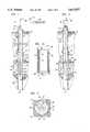
- FIG. 1is a vertical section view of a cased well prepared to have a set of casing perforations blocked or sealed by an apparatus and method of the present invention
- FIG. 2is a view of the well of FIG. 1 after deployment of a perforation blocking sleeve
- FIG. 3is a section view taken from the line 3--3 of FIG. 2;
- FIG. 3Ais a detail view showing a sleeve in a deployed position which has sealant material present on the sleeve;
- FIG. 4is a section view of one preferred embodiment of an apparatus for deploying a perforation blocking and sealing sleeve in accordance with the invention
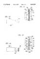
- FIG. 5is a transverse section view taken from the line 5--5 of FIG. 4;
- FIG. 5Ais a transverse section view similar to FIG. 5 illustrating an embodiment of the invention having strands of fuse as the main explosive charge;
- FIG. 6is a transverse section view similar to FIG. 5 showing a first alternate embodiment of a perforation blocking and sealing sleeve
- FIG. 7is a perspective view of the embodiment of the sleeve illustrated in FIG. 6;
- FIG. 8is a longitudinal section view of a well casing and a first alternate embodiment of an apparatus in accordance with the invention.
- FIG. 9is a transverse section view showing a sleeve deployed to block a rupture in the casing illustrated in FIG. 8;
- FIG. 10is a longitudinal central section view of a second alternate embodiment of an apparatus in accordance with the invention.
- FIG. 11is a detail transverse section showing a portion of a second alternate embodiment of a sleeve in accordance with the invention.
- FIG. 12is an uncoiled plan view of the sleeve shown in FIG. 11;
- FIG. 13is a detail transverse section view showing a portion of a third alternate embodiment of a sleeve
- FIG. 14is an uncoiled plan view of the sleeve shown in FIG. 13;
- FIG. 15is a longitudinal section view of a third alternate embodiment of an apparatus in accordance with the invention.
- a conventional cased fluid production well 12extending within an earth formation 14 including a zone 16 from which fluids have been produced during previous operation of the well.
- the well 12includes an elongated casing or liner 18 extending through the formation zone 16 and perforated at multiple perforations 20 through which fluids have been produced from the zone 16.
- the casing 18may, as shown, extend to a surface wellhead 22 of conventional design and from which hangs a production tubing string 24 extending within the well 12 to a lower distal end 26.
- the casing 18may also be connected to a suitable hanger, not shown, disposed intermediate the wellhead 22.
- the wellhead 22is also fitted with a conventional wireline lubricator 28 including a conventional lubricator valve 30.
- the zone 16may, for example, have been depleted of useful production fluids and be producing unwanted water or gas into the wellbore 13. Accordingly, it may be desirable to block some or all of the perforations 20 to prevent fluids from flowing between the formation zone 16 and the wellbore 13.
- Various methodshave been developed in the prior art for blocking the perforations 20 including forming temporary cement plugs which are then drilled out sufficiently to restore the wellbore 13, or bridging the area where the perforations exist by a relatively complicated tubing and packer structure. It is desirable to be able to seal the perforations 20 as simply as possible without providing additional complicated structure or carrying out wellbore operations which may result in having to inject cement mixtures or the like into the well.
- the elastic spring force of the coiled sleevemay not be sufficient to effectively seal the perforations 20 or to prevent unwanted displacement of the sleeve due to high differential pressure between the wellbore space 13 and the formation zone 16.
- the present inventioncontemplates the placement of a perforation or other casing opening blocking and sealing member which may comprise a coiled sleeve similar to that described in the above-mentioned application.
- deployment of the aforementioned sleeve in accordance with the present inventionforms a substantially fluid tight seal at some or all of the perforations 20 and retains the sleeve in its desired position more effectively.
- FIG. 1shows a unique apparatus 34 deployed in the wellbore 13 through the tubing string 24.
- the apparatus 34is connected to suitable deployment means comprising an elongated flexible cable 36 which may comprise suitable electrical conductors disposed within the hollow core of a braided or wound wire rope structural cable member, sometimes known as an electric or E-line.
- the cable 36is operable to be reeled into and out of the wellbore 13 by a conventional cable drum 38 and electrical signals may be transmitted to and through the cable in a manner known to those skilled in the art from a suitable controller 40 for a purpose to be described herein.
- the cable 36is extensible through the wireline lubricator 28 in a conventional manner.
- coilable tubinghaving suitable electrical conductors disposed therein may be used to deploy the apparatus 34 into the well.
- the apparatus 34may include suitable devices for automatic energization of the apparatus based on the pressure in the wellbore, or responsive to other sensors which would identify the position of the apparatus within the well including a gamma ray sensor or a device to count casing collars or other position identifying devices disposed along the casing or conduit through which the apparatus 34 is being conveyed.
- the apparatus 34supports a coiled perforation blocking sleeve 42 thereon which may be radially deployed into engagement with the casing inner wall 19 to effectively block or seal the perforations 20 from communicating fluid between the wellbore 13 and the formation zone 16.
- FIG. 2illustrates the sleeve 42 in its deployed position blocking the perforations 20.
- the sleeve 42may be formed of relatively thin metal plate which is wrapped or coiled into multiple layers so that it may be reduced in diameter and secured on the apparatus 34 for movement into the wellbore 13 through the tubing string 24. Accordingly, the maximum diameter of the apparatus 34 is slightly less than the inside diameter of the tubing 24.
- the apparatus 34may be deployed into the wellbore 13 through the lubricator 28, valve 30 and tubing string 24 in a manner similar to that used for deploying many types of wellbore devices.
- the sleeve 42may be elastically coiled into the position shown in FIG. 1 so that it has a tendency to uncoil and expand radially outward due to its own elastic memory.
- the sleeve 42may be held in its coiled position by suitable means including one or more tack welds 43 along a transverse edge 44.
- the sleeve 42may also be retained in its coiled condition by a weak adhesive between the sleeve layers or wraps. Alternate means for retaining the sleeve 42 in its coiled condition are described below in conjunction with FIG. 4 of the drawing.
- the sleeve 42may also be plastically coiled into the position illustrated in FIG.
- the sleevemay be deployed into engagement with the casing wall 19 by pumping fluid into a distendable bladder, not shown in FIG. 1, positioned inside the apparatus 34 to expand the sleeve into engagement with the casing inner wall 19.
- a distendable bladdernot shown in FIG. 1
- Other means of mechanically expanding the sleeve 42 to engage the casing inner wall 19may also be employed by those skilled in the art.
- FIG. 3illustrates the deployed working position of the sleeve 42 covering all of the perforations 20.
- the sleeve 42is of sufficient width such that, in the uncoiled condition illustrated in FIG. 3, opposite side edges 44 and 45 of the sleeve overlap, as shown, and the forcible deployment of the sleeve into engagement with the casing 18 may result in some plastic deformation of the sleeve into the perforations 20 such as indicated at 47. In this way, a substantially fluid tight seal is formed between the sleeve 42 and the casing 18 along edges which define the perforations 20.
- the sleeve 42may also, in its deployed position, still have multiple layers or wraps of material.
- FIG. 3Aillustrates a sleeve 42 in its deployed position in forcible engagement with the wall 19 of casing 18 and wherein multiple layers or wraps of the sleeve are formed in the deployed position and further wherein a layer of sealant 21 has been applied at least between the layers or wraps of the sleeve 42. In the deployed position, some sealant 21 has been squeezed out of the sleeve 42 at opposite ends to form somewhat beveled layers of sealant 23 and 25, as shown.
- the layers of sealant 23 and 25seal the ends of the sleeve 42 to prevent fluid leakage therealong and between the casing wall 19 and the sleeve. Moreover, the layers of sealant 23 and 25 also provide a continuous surface along the casing wall 18 to minimize the chance of interference of the movement of wellbore tools and devices through the casing 19.
- the sealant 21may be selected from any one of a group consisting of polysulfides, fluorosilicones, polyphosphazenes and combinations thereof.
- the term sealant as used hereinis distinct from the term adhesive. The use of the term adhesive is in the context of a material that is capable of forming a bond between the parts to be secured to each other whereas, the term sealant is used in the context of providing a substantially fluid tight seal to prevent unwanted fluid flow.
- the apparatus 34is illustrated in some detail and is characterized by opposed upper and lower head members 50 and 52 which are interconnected by a center column member 54.
- the column member 54may be threadedly connected to one or the other of the head members 50 and 52.
- the head members 50 and 52preferably have opposed reduced diameter flanges 56 and 58, each having a circumferential elastomeric seal ring 60 disposed thereon and engageable with an inner wrap of the coiled sleeve 42, as illustrated.
- the upper head member 50has a suitable axial projecting threaded portion 62 which is operable to be connected to a conventional cable socket 64 for connecting the apparatus 34 to the cable 36.
- FIG. 4also illustrates a suitable quantity of explosive or high pressure gas generating charge material 66 formed as an annular ring disposed between the flanges 56 and 58.
- the material 66may be a conventional explosive material of a type used in so-called explosive forming or shape modification of metals. Accordingly, the material 66 may be of either the detonating or deflagrating type.
- the explosive material 66may be operable to be energized by spaced apart igniter devices 68 and 70 which are suitably connected to electrical conductor means 72 extending within the column member 54 and the cable 36. Accordingly, the charge material 66 may be energized from the controller 40, at will, to effect displacement of the sleeve 42 into forcible engagement with the casing 18 as described above.
- the sleeve 42may actually require several overlapping wraps or layers 42a, 42b, 42c and 42d, in the radially contracted condition shown, in order for there to be sufficient circumferential length of the sleeve in the deployed position, including some overlap of the edges 44 and 45, to assure that a seal can be formed to substantially prevent fluid flow between the wellbore 13 and the formation zone 16 by way of the perforations 20.
- FIGS. 4 and 5also illustrate a modification to the apparatus 34 wherein plural relatively thin bands or straps 71 are disposed around the sleeve 42 to hold the sleeve disposed on the apparatus in a coiled condition.
- Each of the bands 71may be suitably provided with an explosive charge 73, as shown by example in FIG. 5, suitably connected to conductor means, not shown, operably in communication with the cable 36, to cause the bands to break, at will, to allow the sleeve 42 to deploy into forcible engagement with the casing or conduit wall 19.
- the sleeve 42may be secured against falling out of position through the wellbore 13 by plural flexible cables 33 secured to the head member 50 and to the sleeve 42 at spaced apart points, as indicated in FIG. 4.
- the cables 33are of sufficient length to allow the sleeve 42 to deploy into engagement with the casing wall 19 and, upon igniting the explosive charge 66, the cables may be severed from the sleeve to allow withdrawal of the apparatus 34 from the wellbore 13.
- FIG. 5Aan alternate arrangement of explosive material is illustrated wherein plural strands of commercially available detonator material are provided and generally designated by the numeral 61.
- the strands 61may be formed of a material commercially known as Mild Detonating Fuse.
- the detonator strands 61are disposed in suitable longitudinal grooves formed in the column member 54 and substantially coextensive therewith.
- the explosive chargemay be provided by a sufficient number of the strands 61 or the strands may be augmented by charge material 66 disposed between the head members 50 and 52.
- the apparatus 34may be deployed in the well 12 through the tubing string 24, as previously described, and positioned adjacent a portion of the casing 18 which is desired to be sealed to prevent communication between the wellbore and an earth formation interval.
- the band 71 or tack welds 43, or other means of retaining the sleeve 42 in its coiled conditionare broken by ignition of a suitable detonating fuse, not shown, such as a strip of Mild Detonating Fuse, or other severing means known to those skilled in the art.
- the sleeve 42is then capable of expanding by its own elastic memory or of being forced outward toward the casing wall 19 by other means discussed herein.
- the aforementioned ignitersare then initiated to plastically deform the sleeve 42 into the perforations 20.
- So-called latching mechanismsconstructed of mechanical features or chemical adhesives, as described hereinbelow, may be employed to lock the sleeve 42 in place against the casing wall 19, thus effecting a fluid tight seal between the sleeve and the casing 18.
- the working position of the sleeve 42is illustrated in FIG. 3, wherein the sleeve is plastically deformed with sufficient force to provide for firm engagement of the sleeve with the casing to effectively seal the perforations 20.
- the sleeve 42may be wrapped in the manner described above to provide a small enough diameter that the sleeve may be deployed into the well through a tubing string which is considerably smaller in diameter than the casing or liner to be sealed.
- an elongated sleeve of suitable buffer material 67may be disposed between the charge material 66 and the column member 54.
- This buffer material 67may be a suitable inert thixotropic material for distributing the charge energy and pressure substantially evenly circumferentially around the column member 54 to provide for uniform radial outward expansion of the sleeve 42.
- the inner space occupied by the buffer material 67may be occupied by the charge material 66 and a sleeve of buffer material provided between the charge material and the expansible sleeve 42 to assist in uniform distribution of the radial expansion forces exerted on the sleeve 42.
- the sleeve 76is preferably an elongated seamless or closed seam tubular member having plural radially projecting flutes 78 formed by circumferentially spaced external and internal folds 80 and 82, respectively.
- the sleeve 76may also be formed of multiple layers of this metal, initially coiled, then die formed to provide the folds 80 and 82.
- the explosive charge material 66is disposed between the center column member 54 and the buffer material 67, as illustrated.
- the sleeve 76may be radially expanded into a substantially circular configuration in forcible engagement with the inner wall 19 of the casing 18 in place of the sleeve 42.
- the sleeve 76may be initially expanded into engagement with the casing wall 19 by suitable means such as applying fluid pressure forces thereto.
- suitable meanssuch as applying fluid pressure forces thereto.
- An alternate embodiment of the invention having such a featureis described below in conjunction with FIG. 15.
- the configuration of the sleeve 76, in the undeployed position, as provided by the folds 80 and 82,enables the sleeve to also be of a small diameter sufficient to permit deployment of the sleeve 76 on the apparatus 34 into the well through a tubing string such as the tubing string 24.
- the sleeves 42 and 76may be expanded from their coiled and folded conditions to a substantially cylindrical diameter at least twice their maximum diameters in their coiled and folded positions, respectively.
- a well or other underground passagemay have a casing, liner or other conduit which has ruptured or failed wherein a cylindrical tubular sleeve may be inserted in the conduit and radially expanded into engagement with the conduit inner wall in substantially fluid tight sealing relationship thereto.
- the sleevedoes not require to be substantially radially expansible in the manner of the sleeves 42 or 76 but only in respect to being plastically deformed to a slightly larger diameter.
- FIG. 8shows, for example, a well 90 having a conduit or casing 92 disposed therein which has an unwanted rupture or opening 94 formed in the wall thereof.
- An apparatus 96 in accordance with the inventionis shown disposed in the casing or conduit 92 adjacent the opening 94 and suspended within the well by a cable 36 as described hereinabove.
- the cable 36is adapted to be connected to the controller 40 by way of a cable drum 38, neither of which is shown in FIG. 8.
- the apparatus 96includes opposed head members 98 and 100 interconnected by center column member 102.
- One or more strands of the above-mentioned Mild Detonating Fuse explosive detonator materialmay be disposed on the apparatus 96 between the head members 98 and 100 and along or near the center column member 102 as a preferred means of initiating a charge to plastically deform a tubular sleeve 112 into forcible engagement with the casing 92.
- An alternate method of initiating forcible deployment of the sleeve 112is by use of a quantity of explosive charge material 104 in place of or in addition to the strands of Mild Detonating Fuse material disposed on the apparatus 96 between the head members 98 and 100 and around the column member 102.
- Spaced apart electrically energizable igniters 106 and 108may be provided and operably connected to conductor means 110 in the column member 102 and connected to conductor means 72 within the cable 36.
- the metal tubular sleeve 112is disposed between the head members 98 and 100 and journalling the charge material 104.
- the sleeve 112is a cylindrical tube, preferably seamless, which is operable to be plastically, radially expanded, in response to ignition of the charge material 104, into substantially fluid tight sealing engagement with the inner wall 93 of the conduit or casing 92 to seal the opening 94.
- FIG. 9illustrates the sleeve 112 in its deployed position with the apparatus 96 removed from the interior of the casing 92.
- the sleeves 76 and 112may also be single or multiple layers of relatively thin alloy steel, for example. Alternatively, of course, as previously described, the sleeve may be formed by a continuous wrapped coil of relatively thin steel sheet.
- FIG. 10there is illustrated yet another embodiment of the invention wherein a well 120 has an elongated cylindrical pipe or casing 122 disposed therein and extending below a tubing string 124 having a diameter smaller than the diameter of the casing.
- An apparatus similar to one of the embodiments described in U.S. patent application Ser. No. 08/282,685is shown in FIG. 10 and generally designated by the numeral 128.
- the apparatus 128includes an elongated cylinder 130 which is open at its lower distal end 132 and has a closure head 134 disposed at its opposite end.
- the head 134is suitably connected to an elongated tube 136 which may comprise coilable tubing of the type used in well operations and adapted to be connected to a source of pressure fluid, not shown, at the earth's surface.
- a piston 138is slidably disposed in the cylinder 130 and defines a chamber 140 in the cylinder between the piston 138 and the head 134.
- the piston 138is connected to an elongated rod 142 which is connected to a lower head member 144 having an upwardly projecting circumferential flange portion 146 formed integral therewith, as illustrated.
- An elongated, radially expansible sleeve 148formed of multiple coils or wraps 148a, 148b in the position shown in FIG. 10, is disposed in the cylinder 130 and contained in the coiled condition at its lower distal end 152 by the flange 146.
- the sleeve 148is shorter than the distance between the lower transverse face 139 of the piston 138 and a transverse face 145 of the head 144.
- the sleeve 148is formed of an elastically expandable metal sheet wrapped into a coiled condition to form the wraps 148a, etc., for disposition within the cylinder 130, as illustrated.
- a quantity of explosive charge material 156is disposed around the rod 142 between the sleeve 148 and the rod and is provided with one or more spaced apart electrical igniter devices 158 and 160.
- the igniter devices 158 and 160are connected to suitable electrical conductor means 162 extending within the rod 142 through the piston 138 and is configured with suitable slack takeup coils 164 to be extensive within the tubing 136.
- the conductor means 162also extends within the tubing 136 to the surface and may be suitably connected to a controller 40, not shown in FIG. 10, in the same manner as the embodiments of FIGS. 1 and 8.
- the igniter devices 158 and 160may also be activated by suitable means engageable by the piston 138 as it reaches a limit position upon deployment of the sleeve 148.
- the apparatus 1208In the operation of the apparatus 128, it may be deployed into a desired position within the casing 122 through the tubing 124 and connected to the tubing 136. Once the tubing 136 has been extended into the well, such that the apparatus 128 is disposed beyond the distal end 125 of the tubing 124 and the sleeve 148 is placed adjacent to a portion of the casing to be sealed, pressure fluid may be conducted through the tubing 136 to force the piston 138 to traverse the cylinder 130 toward the distal end 132.
- Initial movement of the piston 138will result in the flange 146 moving away from the distal end 152 of the coiled sleeve 148 to allow the end of the sleeve to radially expand, thanks to the elastic memory of the coils or wraps 148a and 148b.
- the piston 138moves downward, viewing FIG. 10, it will engage the upper end face 149 of the sleeve 148 to push the sleeve out of the cylinder 130 and allow it to radially expand into engagement with the inner wall 123 of the casing 122.
- the movement of the piston 138is limited due to a re-entrant edge, not shown, on the distal end 132 of the cylinder 130.
- the charge material 156may have a suitable seal material provided thereover to minimize or prevent degradation due to exposure to wellbore fluids.
- the explosive charge 156may be detonated to provide a suitable shock wave to forcibly deform the sleeve 148 against the casing 122 and to provide some plastic displacement of the sleeve 148 into the perforations 127 whereby a substantially fluid-tight seal is formed.
- the charge material 156is provided with sufficient energy, upon detonation, to effect deformation of the sleeve 148 as described above, but having energy less than would be destructive to the casing itself. Compression of fluid in the interior of the casing 122 over several hundred or thousand feet may be sufficient to absorb the energy of the explosive charge travelling longitudinally within the casing. Accordingly, with the embodiment illustrated in FIG. 10 and described above, the sleeve 148 may be substantially placed in its working position before the explosive high energy forming process is initiated.
- FIG. 11there is illustrated a fragmentary transverse section view of the casing 18 showing a second alternate embodiment of a coilable type sleeve in accordance with the invention and generally designated by the numeral 160.
- the sleeve 160is similar to the sleeves 42 and 76 except that, preferably, both sides of the sleeve are provided with a coating 162 disposed on an elastically coilable metal plate core or substrate part 163, see FIG. 12 also.
- the coating 162may be a soft metal, such as lead, a thermite material or a pressure activated adhesive, for example.
- the coating 162is a soft metal, it will aid in providing a fluid tight seal between the sleeve 160 and the perforation 20 and will also be of some aid in providing a fluid tight seal between the layers of the sleeve 160 and between the outer layer of the sleeve and the casing wall 19.
- the soft metal coating 162will also easily deform and tend to fill any creases or indentations in the sleeve coils or layers.
- the coating 162is an adhesive, it may be applied to the substrate 163 with sufficient thickness to perform the above-mentioned sealing function and it will also aid in maintaining the sleeve in a deployed position in forcible engagement with the casing 18.
- the coating 162is a thermite material, it may be applied to the substrate 163 in a sufficient quantity to effectively weld the layers of the sleeve 160 together and to the casing wall 19, when energized.
- the thermite materialis, for example, comprised of inert metal powders such as aluminum and iron and is a material well known to those skilled in the art.
- the thermite materialmay be energized by the explosive charge or by other means causing a chemical reaction and generating enough heat to weld the sleeve layers to each other and to the casing wall 19.
- the initiation of the explosive charge material, such as Mild Detonating Fuse, to hydroform the sleeve into the casing perforations or openingis not necessary because the thermite weld provides an adequate seal between the sleeve and the casing or conduit opening or perforations, provided that the sleeve has been securely set in place against the casing or conduit wall.
- Use of the Mild Detonating Fuse material and a thermite coating applied to a sleeveis such that the resulting shock caused by the Mild Detonating Fuse material will energize the thermite material which welds the sleeve as it is being forced into closure of the casing or conduit openings or perforations.
- the Mild Detonating Fuse charge materialfunctions to deform the sleeve into the perforations or openings and also to initiate the thermite welding of the sleeve layers together and to the conduit wall.
- the types of adhesive that may be employedshould comprise, for example, characteristics of being capable of remaining an adhesive in a wide and varying range of temperatures and pressures.
- the adhesivemust be capable of withstanding at least a pressure of 10,000 psi directed from the innermost layer to the outermost layer of the sleeve and be capable of withstanding a pressure of at least 3600 psi directed from the outermost layer to the innermost layer of the sleeve.
- the adhesiveshould also be impervious to saltwater or brine, capable of forming an adhesive bond in an oily environment and capable of forming an adhesive bond in a short period of time (milliseconds).
- Such adhesivesmay be selected from a group consisting of epoxies, polyurethanes, polysulfides, fluorosilicones, polychloroprene rubbers, butadiene rubbers and combinations thereof.
- a third alternate embodiment of a coilable type perforation blocking sleeveis illustrated and generally designated by the numeral 164.
- the sleeve 164may be similar to the sleeve 42 or 160 in other respects but also has plural spaced apart projections 166 and corresponding recesses or indentations 168 formed over at least a portion of the sleeve so that when the multiple layers 164a and 164b, for example, overlap the projections 166 will engage the indentations 168 of the adjacent layer to aid in locking the sleeve in its deployed position.
- the projections 166are not of sufficient height to prevent this action, but once the sleeve has been partially uncoiled into its working position, it is highly likely that at least some of the projections 166 will nest in corresponding indentations 168 to essentially lock the sleeve in its working position.
- the projections 166preferably extend over slightly less than half of the uncoiled length of the sleeve 164. In this way when the sleeve is coiled in its working position shown in FIG. 13, an outer layer 164c of the sleeve which is in engagement with the casing wall 19 will not have the indentations 168 formed therein and which could form a leakage path from one of the perforations 20 into the wellbore 13.
- the projections 166 and corresponding indentations 168may be formed on the sleeve by a suitable coining operation, for example.
- FIG. 15there is illustrated a third alternate embodiment of an apparatus for deploying an expansible sleeve in accordance with the invention and generally designated by the numeral 174.
- the apparatus 174includes spaced apart head portions 176 and 178, similar in some respects to the head portions of the apparatus 34 and interconnected by a center column member 180.
- a radially expansible sleeve 182is disposed on the apparatus 174 between the head portions 174 and 178.
- the sleeve 182may be similar to the sleeve 42 or the sleeve 76, for example.
- a quantity of explosive charge material 184is disposed between the sleeve 182 and the center column member 180 and is adapted to be energized by spaced apart igniters 186 and 188 which, respectively, are adapted to be in communication with an electrical conductor 190.
- the conductor 190extends through the head 176 and within an elongated tubing 192 which may comprise conventional coilable tubing adapted to be reeled onto and off of a suitable tubing reel in a known manner.
- the tubing 192 with the conductor 190 disposed thereinmay be similar to that described in U.S. Pat. No. 4,685,516 to Smith et al. and assigned to Atlantic Richfield Company. Operation of the apparatus 174 in conjunction with the tubing deployment and retrieval apparatus described in the Smith et al. patent is believed to be within the purview of one skilled in the art.
- Pressure fluidmay be conducted through the tubing 192 to the head 176 and through a suitable passage 194 formed in the head and in communication with a suitable fitting 196 connected to an elastically distendable annular bladder member 198 disposed between the heads 176 and 178 and between the sleeve 182 and the charge material 184.
- the bladder member 198defines an annular chamber 199 into which pressure fluid may be conducted through the fitting 196.
- Pressure fluidmay be conducted through the tubing 192 to cause the bladder member 198 to radially distend and force the sleeve 182 radially outwardly into engagement with the inner wall of a casing or tubing, not shown in FIG. 15, prior to detonation of the charge material 184.
- a sleevesuch as the sleeve 182 may be deployed into engagement with the casing or conduit wall prior to detonation of the explosive charge in wellbores wherein, for example, a large quantity of liquid is present in the vicinity of deployment of the sleeve and cannot be evacuated from the well.
- the apparatus 174may be particularly useful in deploying a sleeve similar to the sleeve 76 having the longitudinal flutes or folds so that the sleeve may be deformed into a generally cylindrical configuration in engagement with the casing or conduit wall prior to ignition of the charge material.
- the high energy charge material used in the apparatus described hereinmay be one of a type commercially available for use in so-called explosive metal forming techniques and the associated igniter devices may be conventional explosive igniter elements or detonators.
- the apparatus 34, 96, 128 and 174may be constructed using conventional engineering materials for wellbore devices, suitably reinforced or modified as described herein and to be subjected to the detonation of the explosive charges and to survive such activity in sufficient manner to be retrievable from a working position in a well casing or tubing string.
- the various embodiments of the apparatusmay be traversed into and out of a well using conventional techniques including those described above.
Landscapes
- Life Sciences & Earth Sciences (AREA)
- Engineering & Computer Science (AREA)
- Geology (AREA)
- Mining & Mineral Resources (AREA)
- Physics & Mathematics (AREA)
- Environmental & Geological Engineering (AREA)
- Fluid Mechanics (AREA)
- General Life Sciences & Earth Sciences (AREA)
- Geochemistry & Mineralogy (AREA)
- Pressure Welding/Diffusion-Bonding (AREA)
Abstract
Description
Claims (23)
Priority Applications (1)
| Application Number | Priority Date | Filing Date | Title |
|---|---|---|---|
| US08/448,108US5613557A (en) | 1994-07-29 | 1995-05-23 | Apparatus and method for sealing perforated well casing |
Applications Claiming Priority (2)
| Application Number | Priority Date | Filing Date | Title |
|---|---|---|---|
| US08/282,685US5456319A (en) | 1994-07-29 | 1994-07-29 | Apparatus and method for blocking well perforations |
| US08/448,108US5613557A (en) | 1994-07-29 | 1995-05-23 | Apparatus and method for sealing perforated well casing |
Related Parent Applications (1)
| Application Number | Title | Priority Date | Filing Date |
|---|---|---|---|
| US08/282,685Continuation-In-PartUS5456319A (en) | 1994-07-29 | 1994-07-29 | Apparatus and method for blocking well perforations |
Publications (1)
| Publication Number | Publication Date |
|---|---|
| US5613557Atrue US5613557A (en) | 1997-03-25 |
Family
ID=46250383
Family Applications (1)
| Application Number | Title | Priority Date | Filing Date |
|---|---|---|---|
| US08/448,108Expired - LifetimeUS5613557A (en) | 1994-07-29 | 1995-05-23 | Apparatus and method for sealing perforated well casing |
Country Status (1)
| Country | Link |
|---|---|
| US (1) | US5613557A (en) |
Cited By (112)
| Publication number | Priority date | Publication date | Assignee | Title |
|---|---|---|---|---|
| US5709265A (en) | 1995-12-11 | 1998-01-20 | Weatherford/Lamb, Inc. | Wellbore window formation |
| US5791417A (en) | 1995-09-22 | 1998-08-11 | Weatherford/Lamb, Inc. | Tubular window formation |
| US5833001A (en)* | 1996-12-13 | 1998-11-10 | Schlumberger Technology Corporation | Sealing well casings |
| US6142230A (en)* | 1996-11-14 | 2000-11-07 | Weatherford/Lamb, Inc. | Wellbore tubular patch system |
| WO2001007753A1 (en)* | 1999-07-27 | 2001-02-01 | Shell Internationale Research Maatschappij B.V. | Method of creating a weld in a wellbore |
| US6253850B1 (en)* | 1999-02-24 | 2001-07-03 | Shell Oil Company | Selective zonal isolation within a slotted liner |
| RU2172387C2 (en)* | 1999-08-10 | 2001-08-20 | Открытое акционерное общество "Татнефть" Татарский научно-исследовательский и проектный институт нефти "ТатНИПИнефть" | Shoe for installation of shaped shutoff devices in wells |
| US6328113B1 (en) | 1998-11-16 | 2001-12-11 | Shell Oil Company | Isolation of subterranean zones |
| US6354373B1 (en)* | 1997-11-26 | 2002-03-12 | Schlumberger Technology Corporation | Expandable tubing for a well bore hole and method of expanding |
| GB2366581A (en)* | 2000-09-08 | 2002-03-13 | Baker Hughes Inc | Expanding seal for gravel pack flow aperture |
| US20020040787A1 (en)* | 1998-12-07 | 2002-04-11 | Cook Robert Lance | Forming a wellbore casing while simultaneously drilling a wellbore |
| GB2367842A (en)* | 2000-10-10 | 2002-04-17 | Baker Hughes Inc | An expanding tool for connection between an inner and an outer tubular. |
| US20020100595A1 (en)* | 1999-02-26 | 2002-08-01 | Shell Oil Co. | Flow control system for an apparatus for radially expanding tubular members |
| US6460618B1 (en) | 1999-11-29 | 2002-10-08 | Shell Oil Company | Method and apparatus for improving the permeability in an earth formation utilizing shock waves |
| US6470966B2 (en) | 1998-12-07 | 2002-10-29 | Robert Lance Cook | Apparatus for forming wellbore casing |
| WO2002088510A1 (en)* | 2001-04-27 | 2002-11-07 | Shell Internationale Research Maatschappij B.V. | Drilling system with expandable sleeve |
| US6557640B1 (en) | 1998-12-07 | 2003-05-06 | Shell Oil Company | Lubrication and self-cleaning system for expansion mandrel |
| WO2003046334A1 (en)* | 2001-11-28 | 2003-06-05 | Shell Internationale Research Maatschappij B.V. | Expandable tubes with overlapping end portions |
| US6575240B1 (en) | 1998-12-07 | 2003-06-10 | Shell Oil Company | System and method for driving pipe |
| US6575250B1 (en) | 1999-11-15 | 2003-06-10 | Shell Oil Company | Expanding a tubular element in a wellbore |
| GB2382830A (en)* | 2000-09-08 | 2003-06-11 | Baker Hughes Inc | Gravel pack expanding valve |
| US20030121558A1 (en)* | 1998-11-16 | 2003-07-03 | Cook Robert Lance | Radial expansion of tubular members |
| RU2208125C2 (en)* | 2001-06-18 | 2003-07-10 | Открытое акционерное общество "Татнефть" | Shoe for installation of shaping strutoff device in well |
| US6604763B1 (en) | 1998-12-07 | 2003-08-12 | Shell Oil Company | Expandable connector |
| US6634431B2 (en) | 1998-11-16 | 2003-10-21 | Robert Lance Cook | Isolation of subterranean zones |
| US6640903B1 (en) | 1998-12-07 | 2003-11-04 | Shell Oil Company | Forming a wellbore casing while simultaneously drilling a wellbore |
| US20030222455A1 (en)* | 1999-04-26 | 2003-12-04 | Shell Oil Co. | Expandable connector |
| US6712154B2 (en) | 1998-11-16 | 2004-03-30 | Enventure Global Technology | Isolation of subterranean zones |
| US6745845B2 (en) | 1998-11-16 | 2004-06-08 | Shell Oil Company | Isolation of subterranean zones |
| US20040140103A1 (en)* | 2003-01-21 | 2004-07-22 | Steele David J. | Multi-layer deformable composite construction for use in a subterranean well |
| US6775894B2 (en)* | 2001-07-11 | 2004-08-17 | Aera Energy, Llc | Casing patching tool |
| GB2398323A (en)* | 2001-12-10 | 2004-08-18 | Shell Int Research | Isolation of subterranean zones |
| US6823937B1 (en) | 1998-12-07 | 2004-11-30 | Shell Oil Company | Wellhead |
| US20050086187A1 (en)* | 1999-02-05 | 2005-04-21 | Xfi Corporation | Apparatus and methods for a computer-aided decision-making system |
| US6892819B2 (en) | 1998-12-07 | 2005-05-17 | Shell Oil Company | Forming a wellbore casing while simultaneously drilling a wellbore |
| US20050155773A1 (en)* | 2004-01-21 | 2005-07-21 | Schlumberger Technology Corporation | System and Method to Deploy and Expand Tubular Components Deployed Through Tubing |
| US20050173121A1 (en)* | 2004-02-06 | 2005-08-11 | Steele David J. | Multi-layered wellbore junction |
| US20050230108A1 (en)* | 2002-02-07 | 2005-10-20 | Baker Hughes Incorporated | Liner top test packer |
| US6976541B2 (en) | 2000-09-18 | 2005-12-20 | Shell Oil Company | Liner hanger with sliding sleeve valve |
| GB2417263A (en)* | 2004-08-20 | 2006-02-22 | Louis Jasper Wardlaw | Apparatus and method for repairing failure spots on subterranean well tubulars using shock waves |
| US20060037748A1 (en)* | 2004-08-20 | 2006-02-23 | Wardlaw Louis J | Subterranean well secondary plugging tool for repair of a first plug |
| US7011161B2 (en) | 1998-12-07 | 2006-03-14 | Shell Oil Company | Structural support |
| US7048067B1 (en) | 1999-11-01 | 2006-05-23 | Shell Oil Company | Wellbore casing repair |
| US7055608B2 (en) | 1999-03-11 | 2006-06-06 | Shell Oil Company | Forming a wellbore casing while simultaneously drilling a wellbore |
| US20060180316A1 (en)* | 2005-02-15 | 2006-08-17 | Steele David J | Assembly of downhole equipment in a wellbore |
| US7100685B2 (en) | 2000-10-02 | 2006-09-05 | Enventure Global Technology | Mono-diameter wellbore casing |
| US7100684B2 (en) | 2000-07-28 | 2006-09-05 | Enventure Global Technology | Liner hanger with standoffs |
| US7121352B2 (en) | 1998-11-16 | 2006-10-17 | Enventure Global Technology | Isolation of subterranean zones |
| US20060243452A1 (en)* | 2001-10-23 | 2006-11-02 | Jorg Ernst Eckerlin | System for lining a section of a wellbore |
| US20060260802A1 (en)* | 2003-05-05 | 2006-11-23 | Filippov Andrei G | Expansion device for expanding a pipe |
| US7152687B2 (en) | 2003-11-06 | 2006-12-26 | Halliburton Energy Services, Inc. | Expandable tubular with port valve |
| US7168496B2 (en) | 2001-07-06 | 2007-01-30 | Eventure Global Technology | Liner hanger |
| US7172024B2 (en) | 2000-10-02 | 2007-02-06 | Shell Oil Company | Mono-diameter wellbore casing |
| US7195064B2 (en) | 1998-12-07 | 2007-03-27 | Enventure Global Technology | Mono-diameter wellbore casing |
| US7231985B2 (en) | 1998-11-16 | 2007-06-19 | Shell Oil Company | Radial expansion of tubular members |
| US7234531B2 (en) | 1999-12-03 | 2007-06-26 | Enventure Global Technology, Llc | Mono-diameter wellbore casing |
| US7258168B2 (en) | 2001-07-27 | 2007-08-21 | Enventure Global Technology L.L.C. | Liner hanger with slip joint sealing members and method of use |
| EP1840324A1 (en) | 2006-03-31 | 2007-10-03 | Services Pétroliers Schlumberger | Method and apparatus for selective treatment of a perforated casing |
| US7290605B2 (en) | 2001-12-27 | 2007-11-06 | Enventure Global Technology | Seal receptacle using expandable liner hanger |
| US7290616B2 (en) | 2001-07-06 | 2007-11-06 | Enventure Global Technology, L.L.C. | Liner hanger |
| US7308755B2 (en) | 2003-06-13 | 2007-12-18 | Shell Oil Company | Apparatus for forming a mono-diameter wellbore casing |
| US7325602B2 (en) | 2000-10-02 | 2008-02-05 | Shell Oil Company | Method and apparatus for forming a mono-diameter wellbore casing |
| US7350563B2 (en) | 1999-07-09 | 2008-04-01 | Enventure Global Technology, L.L.C. | System for lining a wellbore casing |
| US7350564B2 (en) | 1998-12-07 | 2008-04-01 | Enventure Global Technology, L.L.C. | Mono-diameter wellbore casing |
| US7360591B2 (en) | 2002-05-29 | 2008-04-22 | Enventure Global Technology, Llc | System for radially expanding a tubular member |
| US7363984B2 (en) | 1998-12-07 | 2008-04-29 | Enventure Global Technology, Llc | System for radially expanding a tubular member |
| US7377326B2 (en) | 2002-08-23 | 2008-05-27 | Enventure Global Technology, L.L.C. | Magnetic impulse applied sleeve method of forming a wellbore casing |
| US7383889B2 (en) | 2001-11-12 | 2008-06-10 | Enventure Global Technology, Llc | Mono diameter wellbore casing |
| US20080142221A1 (en)* | 2006-12-13 | 2008-06-19 | Schlumberger Technology Corporation | Swellable polymeric materials |
| US7398832B2 (en) | 2002-06-10 | 2008-07-15 | Enventure Global Technology, Llc | Mono-diameter wellbore casing |
| US7404444B2 (en) | 2002-09-20 | 2008-07-29 | Enventure Global Technology | Protective sleeve for expandable tubulars |
| US7410000B2 (en) | 2001-01-17 | 2008-08-12 | Enventure Global Technology, Llc. | Mono-diameter wellbore casing |
| US7416027B2 (en) | 2001-09-07 | 2008-08-26 | Enventure Global Technology, Llc | Adjustable expansion cone assembly |
| US7424918B2 (en) | 2002-08-23 | 2008-09-16 | Enventure Global Technology, L.L.C. | Interposed joint sealing layer method of forming a wellbore casing |
| US20080224413A1 (en)* | 2007-03-15 | 2008-09-18 | Doane James C | Sealing material to metal bonding compositions and methods for bonding a sealing material to a metal surface |
| US7438133B2 (en) | 2003-02-26 | 2008-10-21 | Enventure Global Technology, Llc | Apparatus and method for radially expanding and plastically deforming a tubular member |
| US7503393B2 (en) | 2003-01-27 | 2009-03-17 | Enventure Global Technology, Inc. | Lubrication system for radially expanding tubular members |
| US7513313B2 (en) | 2002-09-20 | 2009-04-07 | Enventure Global Technology, Llc | Bottom plug for forming a mono diameter wellbore casing |
| US7516790B2 (en) | 1999-12-03 | 2009-04-14 | Enventure Global Technology, Llc | Mono-diameter wellbore casing |
| US7552776B2 (en) | 1998-12-07 | 2009-06-30 | Enventure Global Technology, Llc | Anchor hangers |
| US7571774B2 (en) | 2002-09-20 | 2009-08-11 | Eventure Global Technology | Self-lubricating expansion mandrel for expandable tubular |
| US7603758B2 (en) | 1998-12-07 | 2009-10-20 | Shell Oil Company | Method of coupling a tubular member |
| US7712522B2 (en) | 2003-09-05 | 2010-05-11 | Enventure Global Technology, Llc | Expansion cone and system |
| US7739917B2 (en) | 2002-09-20 | 2010-06-22 | Enventure Global Technology, Llc | Pipe formability evaluation for expandable tubulars |
| US7740076B2 (en) | 2002-04-12 | 2010-06-22 | Enventure Global Technology, L.L.C. | Protective sleeve for threaded connections for expandable liner hanger |
| US7775290B2 (en) | 2003-04-17 | 2010-08-17 | Enventure Global Technology, Llc | Apparatus for radially expanding and plastically deforming a tubular member |
| US7793721B2 (en) | 2003-03-11 | 2010-09-14 | Eventure Global Technology, Llc | Apparatus for radially expanding and plastically deforming a tubular member |
| US7819185B2 (en) | 2004-08-13 | 2010-10-26 | Enventure Global Technology, Llc | Expandable tubular |
| US7886831B2 (en) | 2003-01-22 | 2011-02-15 | Enventure Global Technology, L.L.C. | Apparatus for radially expanding and plastically deforming a tubular member |
| US7918284B2 (en) | 2002-04-15 | 2011-04-05 | Enventure Global Technology, L.L.C. | Protective sleeve for threaded connections for expandable liner hanger |
| RU2416021C1 (en)* | 2010-05-21 | 2011-04-10 | Открытое акционерное общество "Татнефть" имени В.Д. Шашина | Shoe for placement of profile shutter in well |
| USRE42733E1 (en) | 2001-10-23 | 2011-09-27 | Halliburton Energy Services, Inc. | Wear-resistant, variable diameter expansion tool and expansion methods |
| US8261842B2 (en) | 2009-12-08 | 2012-09-11 | Halliburton Energy Services, Inc. | Expandable wellbore liner system |
| WO2014042818A1 (en)* | 2012-09-17 | 2014-03-20 | Baker Hughes Incorporated | Fluid flow impedance system |
| US8807206B2 (en)* | 2012-11-27 | 2014-08-19 | Halliburton Energy Services, Inc. | Perforating gun debris retention assembly and method of use |
| US8839874B2 (en) | 2012-05-15 | 2014-09-23 | Baker Hughes Incorporated | Packing element backup system |
| US8905149B2 (en) | 2011-06-08 | 2014-12-09 | Baker Hughes Incorporated | Expandable seal with conforming ribs |
| US8955606B2 (en) | 2011-06-03 | 2015-02-17 | Baker Hughes Incorporated | Sealing devices for sealing inner wall surfaces of a wellbore and methods of installing same in a wellbore |
| WO2014108431A3 (en)* | 2013-01-08 | 2015-04-09 | Statoil Petroleum As | A method for plugging a hydrocarbon well |
| US20150211328A1 (en)* | 2014-01-30 | 2015-07-30 | Olympic Research, Inc. | Well sealing via thermite reactions |
| WO2015117924A3 (en)* | 2014-02-05 | 2015-12-10 | Saltel Industries | Expandable device |
| US9228412B2 (en) | 2014-01-30 | 2016-01-05 | Olympic Research, Inc. | Well sealing via thermite reactions |
| US9243490B2 (en) | 2012-12-19 | 2016-01-26 | Baker Hughes Incorporated | Electronically set and retrievable isolation devices for wellbores and methods thereof |
| US20160102526A1 (en)* | 2014-10-08 | 2016-04-14 | Weatherford Technology Holdings, Llc | Stage tool |
| US9394757B2 (en) | 2014-01-30 | 2016-07-19 | Olympic Research, Inc. | Well sealing via thermite reactions |
| US9429236B2 (en) | 2010-11-16 | 2016-08-30 | Baker Hughes Incorporated | Sealing devices having a non-elastomeric fibrous sealing material and methods of using same |
| US20190153809A1 (en)* | 2017-02-15 | 2019-05-23 | China University Of Petroleum - Beijing | Energy-gathered bundle type nesting plugging and wall reinforcing device and application thereof in karst cave plugging |
| US10365079B2 (en)* | 2017-11-01 | 2019-07-30 | Baker Hughes, A Ge Company, Llc | Igniter and ignition device for downhole setting tool power charge |
| US11149517B2 (en) | 2019-01-02 | 2021-10-19 | ISOL8 (Holdings) Limited | Expanding thermite reactions for downhole applications |
| US20220275706A1 (en)* | 2019-09-02 | 2022-09-01 | ISOL8 (Holdings) Limited | Downhole retainer |
| US20220325590A1 (en)* | 2019-07-19 | 2022-10-13 | DynaEnergetics Europe GmbH | Ballistically actuated wellbore tool |
| US20250137359A1 (en)* | 2023-10-31 | 2025-05-01 | Saudi Arabian Oil Company | Systems and methods for anchoring a sub-surface completion unit in a wellbore |
Citations (6)
| Publication number | Priority date | Publication date | Assignee | Title |
|---|---|---|---|---|
| US2214227A (en)* | 1939-03-29 | 1940-09-10 | English Aaron | Method and apparatus for securing objects in wells |
| US3167122A (en)* | 1962-05-04 | 1965-01-26 | Pan American Petroleum Corp | Method and apparatus for repairing casing |
| US3191677A (en)* | 1963-04-29 | 1965-06-29 | Myron M Kinley | Method and apparatus for setting liners in tubing |
| US4662450A (en)* | 1985-09-13 | 1987-05-05 | Haugen David M | Explosively set downhole apparatus |
| US4972906A (en)* | 1989-09-07 | 1990-11-27 | Conoco Inc. | Method for selective plugging of a zone in a well |
| US5456319A (en)* | 1994-07-29 | 1995-10-10 | Atlantic Richfield Company | Apparatus and method for blocking well perforations |
- 1995
- 1995-05-23USUS08/448,108patent/US5613557A/ennot_activeExpired - Lifetime
Patent Citations (6)
| Publication number | Priority date | Publication date | Assignee | Title |
|---|---|---|---|---|
| US2214227A (en)* | 1939-03-29 | 1940-09-10 | English Aaron | Method and apparatus for securing objects in wells |
| US3167122A (en)* | 1962-05-04 | 1965-01-26 | Pan American Petroleum Corp | Method and apparatus for repairing casing |
| US3191677A (en)* | 1963-04-29 | 1965-06-29 | Myron M Kinley | Method and apparatus for setting liners in tubing |
| US4662450A (en)* | 1985-09-13 | 1987-05-05 | Haugen David M | Explosively set downhole apparatus |
| US4972906A (en)* | 1989-09-07 | 1990-11-27 | Conoco Inc. | Method for selective plugging of a zone in a well |
| US5456319A (en)* | 1994-07-29 | 1995-10-10 | Atlantic Richfield Company | Apparatus and method for blocking well perforations |
Cited By (207)
| Publication number | Priority date | Publication date | Assignee | Title |
|---|---|---|---|---|
| US5791417A (en) | 1995-09-22 | 1998-08-11 | Weatherford/Lamb, Inc. | Tubular window formation |
| US5709265A (en) | 1995-12-11 | 1998-01-20 | Weatherford/Lamb, Inc. | Wellbore window formation |
| US6024169A (en) | 1995-12-11 | 2000-02-15 | Weatherford/Lamb, Inc. | Method for window formation in wellbore tubulars |
| US6142230A (en)* | 1996-11-14 | 2000-11-07 | Weatherford/Lamb, Inc. | Wellbore tubular patch system |
| US5833001A (en)* | 1996-12-13 | 1998-11-10 | Schlumberger Technology Corporation | Sealing well casings |
| US6102120A (en)* | 1996-12-13 | 2000-08-15 | Schlumberger Technology Corporation | Zone isolation tools |
| US6354373B1 (en)* | 1997-11-26 | 2002-03-12 | Schlumberger Technology Corporation | Expandable tubing for a well bore hole and method of expanding |
| US7168499B2 (en) | 1998-11-16 | 2007-01-30 | Shell Oil Company | Radial expansion of tubular members |
| US7275601B2 (en) | 1998-11-16 | 2007-10-02 | Shell Oil Company | Radial expansion of tubular members |
| US6328113B1 (en) | 1998-11-16 | 2001-12-11 | Shell Oil Company | Isolation of subterranean zones |
| US20030121558A1 (en)* | 1998-11-16 | 2003-07-03 | Cook Robert Lance | Radial expansion of tubular members |
| US7246667B2 (en) | 1998-11-16 | 2007-07-24 | Shell Oil Company | Radial expansion of tubular members |
| US7231985B2 (en) | 1998-11-16 | 2007-06-19 | Shell Oil Company | Radial expansion of tubular members |
| US7299881B2 (en) | 1998-11-16 | 2007-11-27 | Shell Oil Company | Radial expansion of tubular members |
| US7108072B2 (en) | 1998-11-16 | 2006-09-19 | Shell Oil Company | Lubrication and self-cleaning system for expansion mandrel |
| US7270188B2 (en) | 1998-11-16 | 2007-09-18 | Shell Oil Company | Radial expansion of tubular members |
| US7357190B2 (en) | 1998-11-16 | 2008-04-15 | Shell Oil Company | Radial expansion of tubular members |
| US7121352B2 (en) | 1998-11-16 | 2006-10-17 | Enventure Global Technology | Isolation of subterranean zones |
| US6745845B2 (en) | 1998-11-16 | 2004-06-08 | Shell Oil Company | Isolation of subterranean zones |
| US6712154B2 (en) | 1998-11-16 | 2004-03-30 | Enventure Global Technology | Isolation of subterranean zones |
| US6634431B2 (en) | 1998-11-16 | 2003-10-21 | Robert Lance Cook | Isolation of subterranean zones |
| US20030173090A1 (en)* | 1998-11-16 | 2003-09-18 | Shell Oil Co. | Lubrication and self-cleaning system for expansion mandrel |
| US7357188B1 (en) | 1998-12-07 | 2008-04-15 | Shell Oil Company | Mono-diameter wellbore casing |
| US6725919B2 (en) | 1998-12-07 | 2004-04-27 | Shell Oil Company | Forming a wellbore casing while simultaneously drilling a wellbore |
| US7011161B2 (en) | 1998-12-07 | 2006-03-14 | Shell Oil Company | Structural support |
| US20030098154A1 (en)* | 1998-12-07 | 2003-05-29 | Shell Oil Co. | Apparatus for radially expanding tubular members |
| US7240729B2 (en) | 1998-12-07 | 2007-07-10 | Shell Oil Company | Apparatus for expanding a tubular member |
| US6575240B1 (en) | 1998-12-07 | 2003-06-10 | Shell Oil Company | System and method for driving pipe |
| US7240728B2 (en) | 1998-12-07 | 2007-07-10 | Shell Oil Company | Expandable tubulars with a radial passage and wall portions with different wall thicknesses |
| US20020040787A1 (en)* | 1998-12-07 | 2002-04-11 | Cook Robert Lance | Forming a wellbore casing while simultaneously drilling a wellbore |
| US6561227B2 (en) | 1998-12-07 | 2003-05-13 | Shell Oil Company | Wellbore casing |
| US7216701B2 (en) | 1998-12-07 | 2007-05-15 | Shell Oil Company | Apparatus for expanding a tubular member |
| US6604763B1 (en) | 1998-12-07 | 2003-08-12 | Shell Oil Company | Expandable connector |
| US6557640B1 (en) | 1998-12-07 | 2003-05-06 | Shell Oil Company | Lubrication and self-cleaning system for expansion mandrel |
| US7198100B2 (en) | 1998-12-07 | 2007-04-03 | Shell Oil Company | Apparatus for expanding a tubular member |
| US6631760B2 (en) | 1998-12-07 | 2003-10-14 | Shell Oil Company | Tie back liner for a well system |
| US7195064B2 (en) | 1998-12-07 | 2007-03-27 | Enventure Global Technology | Mono-diameter wellbore casing |
| US7195061B2 (en) | 1998-12-07 | 2007-03-27 | Shell Oil Company | Apparatus for expanding a tubular member |
| US6640903B1 (en) | 1998-12-07 | 2003-11-04 | Shell Oil Company | Forming a wellbore casing while simultaneously drilling a wellbore |
| US7174964B2 (en) | 1998-12-07 | 2007-02-13 | Shell Oil Company | Wellhead with radially expanded tubulars |
| US7159665B2 (en) | 1998-12-07 | 2007-01-09 | Shell Oil Company | Wellbore casing |
| US7036582B2 (en) | 1998-12-07 | 2006-05-02 | Shell Oil Company | Expansion cone for radially expanding tubular members |
| US6497289B1 (en) | 1998-12-07 | 2002-12-24 | Robert Lance Cook | Method of creating a casing in a borehole |
| US7363984B2 (en) | 1998-12-07 | 2008-04-29 | Enventure Global Technology, Llc | System for radially expanding a tubular member |
| US6739392B2 (en) | 1998-12-07 | 2004-05-25 | Shell Oil Company | Forming a wellbore casing while simultaneously drilling a wellbore |
| US7350564B2 (en) | 1998-12-07 | 2008-04-01 | Enventure Global Technology, L.L.C. | Mono-diameter wellbore casing |
| US6758278B2 (en) | 1998-12-07 | 2004-07-06 | Shell Oil Company | Forming a wellbore casing while simultaneously drilling a wellbore |
| US7665532B2 (en) | 1998-12-07 | 2010-02-23 | Shell Oil Company | Pipeline |
| US7603758B2 (en) | 1998-12-07 | 2009-10-20 | Shell Oil Company | Method of coupling a tubular member |
| US7147053B2 (en) | 1998-12-07 | 2006-12-12 | Shell Oil Company | Wellhead |
| US7121337B2 (en) | 1998-12-07 | 2006-10-17 | Shell Oil Company | Apparatus for expanding a tubular member |
| US7108061B2 (en) | 1998-12-07 | 2006-09-19 | Shell Oil Company | Expander for a tapered liner with a shoe |
| US6470966B2 (en) | 1998-12-07 | 2002-10-29 | Robert Lance Cook | Apparatus for forming wellbore casing |
| US6823937B1 (en) | 1998-12-07 | 2004-11-30 | Shell Oil Company | Wellhead |
| US7077213B2 (en) | 1998-12-07 | 2006-07-18 | Shell Oil Company | Expansion cone for radially expanding tubular members |
| US7077211B2 (en) | 1998-12-07 | 2006-07-18 | Shell Oil Company | Method of creating a casing in a borehole |
| US7552776B2 (en) | 1998-12-07 | 2009-06-30 | Enventure Global Technology, Llc | Anchor hangers |
| US7048062B2 (en) | 1998-12-07 | 2006-05-23 | Shell Oil Company | Method of selecting tubular members |
| US7419009B2 (en) | 1998-12-07 | 2008-09-02 | Shell Oil Company | Apparatus for radially expanding and plastically deforming a tubular member |
| US7044218B2 (en) | 1998-12-07 | 2006-05-16 | Shell Oil Company | Apparatus for radially expanding tubular members |
| US6892819B2 (en) | 1998-12-07 | 2005-05-17 | Shell Oil Company | Forming a wellbore casing while simultaneously drilling a wellbore |
| US7434618B2 (en) | 1998-12-07 | 2008-10-14 | Shell Oil Company | Apparatus for expanding a tubular member |
| US20050086187A1 (en)* | 1999-02-05 | 2005-04-21 | Xfi Corporation | Apparatus and methods for a computer-aided decision-making system |
| US6253850B1 (en)* | 1999-02-24 | 2001-07-03 | Shell Oil Company | Selective zonal isolation within a slotted liner |
| US7159667B2 (en) | 1999-02-25 | 2007-01-09 | Shell Oil Company | Method of coupling a tubular member to a preexisting structure |
| US7040396B2 (en) | 1999-02-26 | 2006-05-09 | Shell Oil Company | Apparatus for releasably coupling two elements |
| US7556092B2 (en) | 1999-02-26 | 2009-07-07 | Enventure Global Technology, Llc | Flow control system for an apparatus for radially expanding tubular members |
| US6684947B2 (en) | 1999-02-26 | 2004-02-03 | Shell Oil Company | Apparatus for radially expanding a tubular member |
| US6631759B2 (en) | 1999-02-26 | 2003-10-14 | Shell Oil Company | Apparatus for radially expanding a tubular member |
| US6966370B2 (en) | 1999-02-26 | 2005-11-22 | Shell Oil Company | Apparatus for actuating an annular piston |
| US6568471B1 (en) | 1999-02-26 | 2003-05-27 | Shell Oil Company | Liner hanger |
| US6631769B2 (en) | 1999-02-26 | 2003-10-14 | Shell Oil Company | Method of operating an apparatus for radially expanding a tubular member |
| US20020100595A1 (en)* | 1999-02-26 | 2002-08-01 | Shell Oil Co. | Flow control system for an apparatus for radially expanding tubular members |
| US7044221B2 (en) | 1999-02-26 | 2006-05-16 | Shell Oil Company | Apparatus for coupling a tubular member to a preexisting structure |
| US6857473B2 (en) | 1999-02-26 | 2005-02-22 | Shell Oil Company | Method of coupling a tubular member to a preexisting structure |
| US6705395B2 (en) | 1999-02-26 | 2004-03-16 | Shell Oil Company | Wellbore casing |
| US7063142B2 (en) | 1999-02-26 | 2006-06-20 | Shell Oil Company | Method of applying an axial force to an expansion cone |
| US7055608B2 (en) | 1999-03-11 | 2006-06-06 | Shell Oil Company | Forming a wellbore casing while simultaneously drilling a wellbore |
| US7438132B2 (en) | 1999-03-11 | 2008-10-21 | Shell Oil Company | Concentric pipes expanded at the pipe ends and method of forming |
| US20030222455A1 (en)* | 1999-04-26 | 2003-12-04 | Shell Oil Co. | Expandable connector |
| US6968618B2 (en) | 1999-04-26 | 2005-11-29 | Shell Oil Company | Expandable connector |
| US7350563B2 (en) | 1999-07-09 | 2008-04-01 | Enventure Global Technology, L.L.C. | System for lining a wellbore casing |
| WO2001007753A1 (en)* | 1999-07-27 | 2001-02-01 | Shell Internationale Research Maatschappij B.V. | Method of creating a weld in a wellbore |
| RU2172387C2 (en)* | 1999-08-10 | 2001-08-20 | Открытое акционерное общество "Татнефть" Татарский научно-исследовательский и проектный институт нефти "ТатНИПИнефть" | Shoe for installation of shaped shutoff devices in wells |
| US7048067B1 (en) | 1999-11-01 | 2006-05-23 | Shell Oil Company | Wellbore casing repair |
| US6575250B1 (en) | 1999-11-15 | 2003-06-10 | Shell Oil Company | Expanding a tubular element in a wellbore |
| US6460618B1 (en) | 1999-11-29 | 2002-10-08 | Shell Oil Company | Method and apparatus for improving the permeability in an earth formation utilizing shock waves |
| US7234531B2 (en) | 1999-12-03 | 2007-06-26 | Enventure Global Technology, Llc | Mono-diameter wellbore casing |
| US7516790B2 (en) | 1999-12-03 | 2009-04-14 | Enventure Global Technology, Llc | Mono-diameter wellbore casing |
| US7100684B2 (en) | 2000-07-28 | 2006-09-05 | Enventure Global Technology | Liner hanger with standoffs |
| GB2382830A (en)* | 2000-09-08 | 2003-06-11 | Baker Hughes Inc | Gravel pack expanding valve |
| GB2366581A (en)* | 2000-09-08 | 2002-03-13 | Baker Hughes Inc | Expanding seal for gravel pack flow aperture |
| GB2366581B (en)* | 2000-09-08 | 2003-03-19 | Baker Hughes Inc | Gravel pack expanding valve |
| US7172021B2 (en) | 2000-09-18 | 2007-02-06 | Shell Oil Company | Liner hanger with sliding sleeve valve |
| US6976541B2 (en) | 2000-09-18 | 2005-12-20 | Shell Oil Company | Liner hanger with sliding sleeve valve |
| US7201223B2 (en) | 2000-10-02 | 2007-04-10 | Shell Oil Company | Method and apparatus for forming a mono-diameter wellbore casing |
| US7172024B2 (en) | 2000-10-02 | 2007-02-06 | Shell Oil Company | Mono-diameter wellbore casing |
| US7363690B2 (en) | 2000-10-02 | 2008-04-29 | Shell Oil Company | Method and apparatus for forming a mono-diameter wellbore casing |
| US7363691B2 (en) | 2000-10-02 | 2008-04-29 | Shell Oil Company | Method and apparatus for forming a mono-diameter wellbore casing |
| US7172019B2 (en) | 2000-10-02 | 2007-02-06 | Shell Oil Company | Method and apparatus for forming a mono-diameter wellbore casing |
| US7146702B2 (en) | 2000-10-02 | 2006-12-12 | Shell Oil Company | Method and apparatus for forming a mono-diameter wellbore casing |
| US7100685B2 (en) | 2000-10-02 | 2006-09-05 | Enventure Global Technology | Mono-diameter wellbore casing |
| US7325602B2 (en) | 2000-10-02 | 2008-02-05 | Shell Oil Company | Method and apparatus for forming a mono-diameter wellbore casing |
| US7204007B2 (en) | 2000-10-02 | 2007-04-17 | Shell Oil Company | Method and apparatus for forming a mono-diameter wellbore casing |
| US6450261B1 (en) | 2000-10-10 | 2002-09-17 | Baker Hughes Incorporated | Flexible swedge |
| GB2367842A (en)* | 2000-10-10 | 2002-04-17 | Baker Hughes Inc | An expanding tool for connection between an inner and an outer tubular. |
| GB2367842B (en)* | 2000-10-10 | 2003-05-14 | Baker Hughes Inc | Flexible swedge |
| US7410000B2 (en) | 2001-01-17 | 2008-08-12 | Enventure Global Technology, Llc. | Mono-diameter wellbore casing |
| US20040144568A1 (en)* | 2001-04-27 | 2004-07-29 | Van Dijk Robert Albertus | Drilling system with expandable sleeve |
| AU2002314030B2 (en)* | 2001-04-27 | 2007-06-21 | Shell Internationale Research Maatschappij B.V. | Drilling system with expandable sleeve |
| WO2002088510A1 (en)* | 2001-04-27 | 2002-11-07 | Shell Internationale Research Maatschappij B.V. | Drilling system with expandable sleeve |
| US7159673B2 (en) | 2001-04-27 | 2007-01-09 | Shell Oil Company | Drilling system with expandable sleeve |
| RU2208125C2 (en)* | 2001-06-18 | 2003-07-10 | Открытое акционерное общество "Татнефть" | Shoe for installation of shaping strutoff device in well |
| US7168496B2 (en) | 2001-07-06 | 2007-01-30 | Eventure Global Technology | Liner hanger |
| US7290616B2 (en) | 2001-07-06 | 2007-11-06 | Enventure Global Technology, L.L.C. | Liner hanger |
| US6775894B2 (en)* | 2001-07-11 | 2004-08-17 | Aera Energy, Llc | Casing patching tool |
| US7258168B2 (en) | 2001-07-27 | 2007-08-21 | Enventure Global Technology L.L.C. | Liner hanger with slip joint sealing members and method of use |
| US7416027B2 (en) | 2001-09-07 | 2008-08-26 | Enventure Global Technology, Llc | Adjustable expansion cone assembly |
| US20060243452A1 (en)* | 2001-10-23 | 2006-11-02 | Jorg Ernst Eckerlin | System for lining a section of a wellbore |
| US7172025B2 (en) | 2001-10-23 | 2007-02-06 | Shell Oil Company | System for lining a section of a wellbore |
| USRE42733E1 (en) | 2001-10-23 | 2011-09-27 | Halliburton Energy Services, Inc. | Wear-resistant, variable diameter expansion tool and expansion methods |
| US7559365B2 (en) | 2001-11-12 | 2009-07-14 | Enventure Global Technology, Llc | Collapsible expansion cone |
| US7383889B2 (en) | 2001-11-12 | 2008-06-10 | Enventure Global Technology, Llc | Mono diameter wellbore casing |
| GB2399116A (en)* | 2001-11-28 | 2004-09-08 | Shell Int Research | Expandable tubes with overlapping end portions |
| GB2399116B (en)* | 2001-11-28 | 2005-06-08 | Shell Int Research | Expandable tubes with overlapping end portions |
| WO2003046334A1 (en)* | 2001-11-28 | 2003-06-05 | Shell Internationale Research Maatschappij B.V. | Expandable tubes with overlapping end portions |
| US7380593B2 (en) | 2001-11-28 | 2008-06-03 | Shell Oil Company | Expandable tubes with overlapping end portions |
| US20050039910A1 (en)* | 2001-11-28 | 2005-02-24 | Lohbeck Wilhelmus Christianus Maria | Expandable tubes with overlapping end portions |
| GB2398323A (en)* | 2001-12-10 | 2004-08-18 | Shell Int Research | Isolation of subterranean zones |
| GB2398323B (en)* | 2001-12-10 | 2005-03-23 | Shell Int Research | Isolation of subterranean zones |
| US7290605B2 (en) | 2001-12-27 | 2007-11-06 | Enventure Global Technology | Seal receptacle using expandable liner hanger |
| US20050230108A1 (en)* | 2002-02-07 | 2005-10-20 | Baker Hughes Incorporated | Liner top test packer |
| US7740076B2 (en) | 2002-04-12 | 2010-06-22 | Enventure Global Technology, L.L.C. | Protective sleeve for threaded connections for expandable liner hanger |
| US7918284B2 (en) | 2002-04-15 | 2011-04-05 | Enventure Global Technology, L.L.C. | Protective sleeve for threaded connections for expandable liner hanger |
| US7360591B2 (en) | 2002-05-29 | 2008-04-22 | Enventure Global Technology, Llc | System for radially expanding a tubular member |
| US7398832B2 (en) | 2002-06-10 | 2008-07-15 | Enventure Global Technology, Llc | Mono-diameter wellbore casing |
| US7424918B2 (en) | 2002-08-23 | 2008-09-16 | Enventure Global Technology, L.L.C. | Interposed joint sealing layer method of forming a wellbore casing |
| US7377326B2 (en) | 2002-08-23 | 2008-05-27 | Enventure Global Technology, L.L.C. | Magnetic impulse applied sleeve method of forming a wellbore casing |
| US7739917B2 (en) | 2002-09-20 | 2010-06-22 | Enventure Global Technology, Llc | Pipe formability evaluation for expandable tubulars |
| US7513313B2 (en) | 2002-09-20 | 2009-04-07 | Enventure Global Technology, Llc | Bottom plug for forming a mono diameter wellbore casing |
| US7404444B2 (en) | 2002-09-20 | 2008-07-29 | Enventure Global Technology | Protective sleeve for expandable tubulars |
| US7571774B2 (en) | 2002-09-20 | 2009-08-11 | Eventure Global Technology | Self-lubricating expansion mandrel for expandable tubular |
| US20040140103A1 (en)* | 2003-01-21 | 2004-07-22 | Steele David J. | Multi-layer deformable composite construction for use in a subterranean well |
| FR2850128A1 (en)* | 2003-01-21 | 2004-07-23 | Halliburton Energy Serv Inc | MULTI-LAYERED DEFORMABLE COMPOSITE STRUCTURE FOR USE IN A SUBTERRANEAN WELL. |
| US6863130B2 (en)* | 2003-01-21 | 2005-03-08 | Halliburton Energy Services, Inc. | Multi-layer deformable composite construction for use in a subterranean well |
| US20060185856A1 (en)* | 2003-01-21 | 2006-08-24 | Steele David J | Multi-layer deformable composite construction for use in a subterranean well |
| US7216718B2 (en) | 2003-01-21 | 2007-05-15 | Halliburton Energy Services, Inc. | Multi-layer deformable composite construction for use in a subterranean well |
| US7063163B2 (en) | 2003-01-21 | 2006-06-20 | Halliburton Energy Services, Inc. | Multi-layer deformable composite construction for use in a subterranean well |
| US20050087345A1 (en)* | 2003-01-21 | 2005-04-28 | Halliburton Energy Services, Inc. | Multi-layer deformable composite construction for use in a subterranean well |
| US7886831B2 (en) | 2003-01-22 | 2011-02-15 | Enventure Global Technology, L.L.C. | Apparatus for radially expanding and plastically deforming a tubular member |
| US7503393B2 (en) | 2003-01-27 | 2009-03-17 | Enventure Global Technology, Inc. | Lubrication system for radially expanding tubular members |
| US7438133B2 (en) | 2003-02-26 | 2008-10-21 | Enventure Global Technology, Llc | Apparatus and method for radially expanding and plastically deforming a tubular member |
| US7793721B2 (en) | 2003-03-11 | 2010-09-14 | Eventure Global Technology, Llc | Apparatus for radially expanding and plastically deforming a tubular member |
| US7775290B2 (en) | 2003-04-17 | 2010-08-17 | Enventure Global Technology, Llc | Apparatus for radially expanding and plastically deforming a tubular member |
| US20060260802A1 (en)* | 2003-05-05 | 2006-11-23 | Filippov Andrei G | Expansion device for expanding a pipe |
| US7597140B2 (en) | 2003-05-05 | 2009-10-06 | Shell Oil Company | Expansion device for expanding a pipe |
| US7308755B2 (en) | 2003-06-13 | 2007-12-18 | Shell Oil Company | Apparatus for forming a mono-diameter wellbore casing |
| US7712522B2 (en) | 2003-09-05 | 2010-05-11 | Enventure Global Technology, Llc | Expansion cone and system |
| US7152687B2 (en) | 2003-11-06 | 2006-12-26 | Halliburton Energy Services, Inc. | Expandable tubular with port valve |
| US20050155773A1 (en)* | 2004-01-21 | 2005-07-21 | Schlumberger Technology Corporation | System and Method to Deploy and Expand Tubular Components Deployed Through Tubing |
| US7380595B2 (en)* | 2004-01-21 | 2008-06-03 | Schlumberger Technology Corporation | System and method to deploy and expand tubular components deployed through tubing |
| US7225875B2 (en)* | 2004-02-06 | 2007-06-05 | Halliburton Energy Services, Inc. | Multi-layered wellbore junction |
| US20050173121A1 (en)* | 2004-02-06 | 2005-08-11 | Steele David J. | Multi-layered wellbore junction |
| US7819185B2 (en) | 2004-08-13 | 2010-10-26 | Enventure Global Technology, Llc | Expandable tubular |
| GB2417263B (en)* | 2004-08-20 | 2009-09-23 | Louis Jasper Wardlaw | An apparatus and method for repairing a tubular |
| GB2417263A (en)* | 2004-08-20 | 2006-02-22 | Louis Jasper Wardlaw | Apparatus and method for repairing failure spots on subterranean well tubulars using shock waves |
| US20060037748A1 (en)* | 2004-08-20 | 2006-02-23 | Wardlaw Louis J | Subterranean well secondary plugging tool for repair of a first plug |
| US20070175634A1 (en)* | 2004-08-20 | 2007-08-02 | Wardlaw Louis J | Apparatus and method for repairing failure spots on subterranean well tubulars using shock waves |
| US7290609B2 (en)* | 2004-08-20 | 2007-11-06 | Cinaruco International S.A. Calle Aguilino De La Guardia | Subterranean well secondary plugging tool for repair of a first plug |
| US20060180316A1 (en)* | 2005-02-15 | 2006-08-17 | Steele David J | Assembly of downhole equipment in a wellbore |
| US7320366B2 (en) | 2005-02-15 | 2008-01-22 | Halliburton Energy Services, Inc. | Assembly of downhole equipment in a wellbore |
| US20100025036A1 (en)* | 2006-03-31 | 2010-02-04 | Philippe Gambier | Method and Apparatus for Selective Treatment of a Perforated Casing |
| US8474523B2 (en) | 2006-03-31 | 2013-07-02 | Schlumberger Technology Corporation | Method and apparatus for treatment of a perforated casing |
| US8312921B2 (en) | 2006-03-31 | 2012-11-20 | Schlumberger Technology Corporation | Method and apparatus for selective treatment of a perforated casing |
| EP1840324A1 (en) | 2006-03-31 | 2007-10-03 | Services Pétroliers Schlumberger | Method and apparatus for selective treatment of a perforated casing |
| US7665538B2 (en) | 2006-12-13 | 2010-02-23 | Schlumberger Technology Corporation | Swellable polymeric materials |
| US20080142221A1 (en)* | 2006-12-13 | 2008-06-19 | Schlumberger Technology Corporation | Swellable polymeric materials |
| US20100108308A1 (en)* | 2007-03-15 | 2010-05-06 | Doane James C | Sealing material to metal bonding compositions and methods for bonding a sealing material to a metal surface |
| US20080224413A1 (en)* | 2007-03-15 | 2008-09-18 | Doane James C | Sealing material to metal bonding compositions and methods for bonding a sealing material to a metal surface |
| US20100108253A1 (en)* | 2007-03-15 | 2010-05-06 | Doane James C | Sealing material to metal bonding compositions and methods for bonding a sealing material to a metal surface |
| US8261842B2 (en) | 2009-12-08 | 2012-09-11 | Halliburton Energy Services, Inc. | Expandable wellbore liner system |
| RU2416021C1 (en)* | 2010-05-21 | 2011-04-10 | Открытое акционерное общество "Татнефть" имени В.Д. Шашина | Shoe for placement of profile shutter in well |
| US9429236B2 (en) | 2010-11-16 | 2016-08-30 | Baker Hughes Incorporated | Sealing devices having a non-elastomeric fibrous sealing material and methods of using same |
| US8955606B2 (en) | 2011-06-03 | 2015-02-17 | Baker Hughes Incorporated | Sealing devices for sealing inner wall surfaces of a wellbore and methods of installing same in a wellbore |
| US8905149B2 (en) | 2011-06-08 | 2014-12-09 | Baker Hughes Incorporated | Expandable seal with conforming ribs |
| US8839874B2 (en) | 2012-05-15 | 2014-09-23 | Baker Hughes Incorporated | Packing element backup system |
| WO2014042818A1 (en)* | 2012-09-17 | 2014-03-20 | Baker Hughes Incorporated | Fluid flow impedance system |
| US8807206B2 (en)* | 2012-11-27 | 2014-08-19 | Halliburton Energy Services, Inc. | Perforating gun debris retention assembly and method of use |
| US9243490B2 (en) | 2012-12-19 | 2016-01-26 | Baker Hughes Incorporated | Electronically set and retrievable isolation devices for wellbores and methods thereof |
| WO2014108431A3 (en)* | 2013-01-08 | 2015-04-09 | Statoil Petroleum As | A method for plugging a hydrocarbon well |
| US20150211328A1 (en)* | 2014-01-30 | 2015-07-30 | Olympic Research, Inc. | Well sealing via thermite reactions |
| US9228412B2 (en) | 2014-01-30 | 2016-01-05 | Olympic Research, Inc. | Well sealing via thermite reactions |
| US9494011B1 (en) | 2014-01-30 | 2016-11-15 | Olympic Research, Inc. | Well sealing via thermite reactions |
| US9394757B2 (en) | 2014-01-30 | 2016-07-19 | Olympic Research, Inc. | Well sealing via thermite reactions |
| WO2015117924A3 (en)* | 2014-02-05 | 2015-12-10 | Saltel Industries | Expandable device |
| US20160102526A1 (en)* | 2014-10-08 | 2016-04-14 | Weatherford Technology Holdings, Llc | Stage tool |
| US11840905B2 (en)* | 2014-10-08 | 2023-12-12 | Weatherford Technology Holdings, Llc | Stage tool |
| US20190153809A1 (en)* | 2017-02-15 | 2019-05-23 | China University Of Petroleum - Beijing | Energy-gathered bundle type nesting plugging and wall reinforcing device and application thereof in karst cave plugging |
| US10822913B2 (en)* | 2017-02-15 | 2020-11-03 | China University Of Petroleum-Beijing | Energy-gathered bundle type nesting plugging and wall reinforcing device and application thereof in karst cave plugging |
| US10365079B2 (en)* | 2017-11-01 | 2019-07-30 | Baker Hughes, A Ge Company, Llc | Igniter and ignition device for downhole setting tool power charge |
| US11149517B2 (en) | 2019-01-02 | 2021-10-19 | ISOL8 (Holdings) Limited | Expanding thermite reactions for downhole applications |
| US20220325590A1 (en)* | 2019-07-19 | 2022-10-13 | DynaEnergetics Europe GmbH | Ballistically actuated wellbore tool |
| US11834920B2 (en)* | 2019-07-19 | 2023-12-05 | DynaEnergetics Europe GmbH | Ballistically actuated wellbore tool |
| US12110751B2 (en) | 2019-07-19 | 2024-10-08 | DynaEnergetics Europe GmbH | Ballistically actuated wellbore tool |
| US20220275706A1 (en)* | 2019-09-02 | 2022-09-01 | ISOL8 (Holdings) Limited | Downhole retainer |
| US12116866B2 (en)* | 2019-09-02 | 2024-10-15 | ISOL8 (Holdings) Limited | Downhole retainer |
| US20250137359A1 (en)* | 2023-10-31 | 2025-05-01 | Saudi Arabian Oil Company | Systems and methods for anchoring a sub-surface completion unit in a wellbore |
Similar Documents
| Publication | Publication Date | Title |
|---|---|---|
| US5613557A (en) | Apparatus and method for sealing perforated well casing | |
| US11542766B2 (en) | Compact setting tool | |
| US3167122A (en) | Method and apparatus for repairing casing | |
| EP1080296B1 (en) | Deformable liner tube | |
| CA2366874C (en) | Wellbore isolation technique | |
| RU2108448C1 (en) | Method for completion of uncased part of bore-hole | |
| US6854522B2 (en) | Annular isolators for expandable tubulars in wellbores | |
| CN101460699B (en) | A method and apparatus for patching a well by hydroforming a tubular metal patch, and a patch for this purpose | |
| EP2312119A1 (en) | An annular barrier | |
| US7870895B2 (en) | Packer | |
| EP2418348B1 (en) | Filler rings for swellable packers | |
| CA2509414C (en) | Method and apparatus for positioning a sleeve down hole in a hydrocarbon producing well and pipelines | |
| US10837264B2 (en) | Casing patch system | |
| US4716832A (en) | High temperature high pressure detonator | |
| US6626240B1 (en) | Device for annular well isolation | |
| MXPA02005119A (en) | Setting an annular seal. | |
| US11560769B2 (en) | Wire line deployable metal patch stackable system | |
| WO2021150120A1 (en) | Retrofit expandable annulus sealing (reas) | |
| EA040920B1 (en) | PROTECT PACKER ELEMENT CONSUMABLE MATERIAL FOR IMPROVED RUNNING TIME |
Legal Events
| Date | Code | Title | Description |
|---|---|---|---|
| AS | Assignment | Owner name:ATLANTIC RICHFIELD COMPANY, CALIFORNIA Free format text:ASSIGNMENT OF ASSIGNORS INTEREST;ASSIGNORS:BLOUNT, CURTIS G.;FERGUSON, KEITH R.;SCHEVE, DONALD F.;AND OTHERS;REEL/FRAME:007522/0332;SIGNING DATES FROM 19950426 TO 19950508 | |
| STCF | Information on status: patent grant | Free format text:PATENTED CASE | |
| FPAY | Fee payment | Year of fee payment:4 | |
| AS | Assignment | Owner name:PHILLIPS PETROLEUM COMPANY, OKLAHOMA Free format text:ASSIGNMENT OF ASSIGNORS INTEREST;ASSIGNOR:ATLANTIC RICHFIELD COMPANY;REEL/FRAME:012333/0329 Effective date:20010920 | |
| FEPP | Fee payment procedure | Free format text:PAYOR NUMBER ASSIGNED (ORIGINAL EVENT CODE: ASPN); ENTITY STATUS OF PATENT OWNER: LARGE ENTITY | |
| FPAY | Fee payment | Year of fee payment:8 | |
| FPAY | Fee payment | Year of fee payment:12 | |
| AS | Assignment | Owner name:CONOCOPHILLIPS COMPANY, TEXAS Free format text:CHANGE OF NAME;ASSIGNOR:PHILLIPS PETROLEUM COMPANY;REEL/FRAME:022793/0106 Effective date:20021212 |