US5613509A - Method and apparatus for removing contaminants and coatings from a substrate using pulsed radiant energy and liquid carbon dioxide - Google Patents
Method and apparatus for removing contaminants and coatings from a substrate using pulsed radiant energy and liquid carbon dioxideDownload PDFInfo
- Publication number
- US5613509A US5613509AUS08/460,732US46073295AUS5613509AUS 5613509 AUS5613509 AUS 5613509AUS 46073295 AUS46073295 AUS 46073295AUS 5613509 AUS5613509 AUS 5613509A
- Authority
- US
- United States
- Prior art keywords
- carbon dioxide
- liquid carbon
- source
- target area
- stream
- Prior art date
- Legal status (The legal status is an assumption and is not a legal conclusion. Google has not performed a legal analysis and makes no representation as to the accuracy of the status listed.)
- Expired - Fee Related
Links
Images


Classifications
- B—PERFORMING OPERATIONS; TRANSPORTING
- B24—GRINDING; POLISHING
- B24C—ABRASIVE OR RELATED BLASTING WITH PARTICULATE MATERIAL
- B24C1/00—Methods for use of abrasive blasting for producing particular effects; Use of auxiliary equipment in connection with such methods
- B24C1/08—Methods for use of abrasive blasting for producing particular effects; Use of auxiliary equipment in connection with such methods for polishing surfaces, e.g. smoothing a surface by making use of liquid-borne abrasives
- B24C1/086—Descaling; Removing coating films
- B—PERFORMING OPERATIONS; TRANSPORTING
- B08—CLEANING
- B08B—CLEANING IN GENERAL; PREVENTION OF FOULING IN GENERAL
- B08B7/00—Cleaning by methods not provided for in a single other subclass or a single group in this subclass
- B08B7/0035—Cleaning by methods not provided for in a single other subclass or a single group in this subclass by radiant energy, e.g. UV, laser, light beam or the like
- B08B7/0042—Cleaning by methods not provided for in a single other subclass or a single group in this subclass by radiant energy, e.g. UV, laser, light beam or the like by laser
- B—PERFORMING OPERATIONS; TRANSPORTING
- B23—MACHINE TOOLS; METAL-WORKING NOT OTHERWISE PROVIDED FOR
- B23K—SOLDERING OR UNSOLDERING; WELDING; CLADDING OR PLATING BY SOLDERING OR WELDING; CUTTING BY APPLYING HEAT LOCALLY, e.g. FLAME CUTTING; WORKING BY LASER BEAM
- B23K26/00—Working by laser beam, e.g. welding, cutting or boring
- B23K26/14—Working by laser beam, e.g. welding, cutting or boring using a fluid stream, e.g. a jet of gas, in conjunction with the laser beam; Nozzles therefor
- B23K26/144—Working by laser beam, e.g. welding, cutting or boring using a fluid stream, e.g. a jet of gas, in conjunction with the laser beam; Nozzles therefor the fluid stream containing particles, e.g. powder
- B—PERFORMING OPERATIONS; TRANSPORTING
- B23—MACHINE TOOLS; METAL-WORKING NOT OTHERWISE PROVIDED FOR
- B23K—SOLDERING OR UNSOLDERING; WELDING; CLADDING OR PLATING BY SOLDERING OR WELDING; CUTTING BY APPLYING HEAT LOCALLY, e.g. FLAME CUTTING; WORKING BY LASER BEAM
- B23K26/00—Working by laser beam, e.g. welding, cutting or boring
- B23K26/36—Removing material
- B23K26/362—Laser etching
- B23K26/364—Laser etching for making a groove or trench, e.g. for scribing a break initiation groove
- B—PERFORMING OPERATIONS; TRANSPORTING
- B24—GRINDING; POLISHING
- B24C—ABRASIVE OR RELATED BLASTING WITH PARTICULATE MATERIAL
- B24C1/00—Methods for use of abrasive blasting for producing particular effects; Use of auxiliary equipment in connection with such methods
- B24C1/003—Methods for use of abrasive blasting for producing particular effects; Use of auxiliary equipment in connection with such methods using material which dissolves or changes phase after the treatment, e.g. ice, CO2
- B—PERFORMING OPERATIONS; TRANSPORTING
- B44—DECORATIVE ARTS
- B44D—PAINTING OR ARTISTIC DRAWING, NOT OTHERWISE PROVIDED FOR; PRESERVING PAINTINGS; SURFACE TREATMENT TO OBTAIN SPECIAL ARTISTIC SURFACE EFFECTS OR FINISHES
- B44D3/00—Accessories or implements for use in connection with painting or artistic drawing, not otherwise provided for; Methods or devices for colour determination, selection, or synthesis, e.g. use of colour tables
- B44D3/16—Implements or apparatus for removing dry paint from surfaces, e.g. by scraping, by burning
- B44D3/166—Implements or apparatus for removing dry paint from surfaces, e.g. by scraping, by burning by heating, e.g. by burning
Definitions
- the present inventionrelates to an improved material removal method and system, and more particularly, to a material removal method and system that uses an intense, pulsed light source to pyrolyze and/or ablate contaminants or coatings on a substrate and a source of liquid carbon dioxide which undergoes phase transition to low temperature carbon dioxide gas and carbon dioxide snow which is subsequently directed towards the substrate to remove the contaminant or coating while simultaneously cleaning and cooling the substrate surface.
- Material coatingsplay an important role in our manufactured-products-based society. Coatings such as paints, lacquers, adhesives, resins, diamond films, and polymer films are used on many products used in both commercial and military applications. Material coatings will often improve the reliability, maintainability and quality of many products including microelectronics, optical surfaces, machinery, vehicles and standing structures. Such coatings provide immunity to corrosion, thermal insulation, as well as environmental shielding. In some applications the material coatings are required for very complex and specialized functions. These material coatings are selected because of specialized properties such as radio frequency absorbing properties, light absorption or reflection properties, and other predetermined optical properties. Many coatings are applied merely for aesthetic purposes such as appearance enhancement or item identification.
- paint coatingsrequire removal and replacement for a variety of reasons. For example, refurbishment of the paint on aircraft is a regular maintenance item. Commercial airlines repaint their aircraft about every 4-5 years of service. The United States military typically repaints its aircraft after three years of service, or less. Coatings on the exterior surfaces of large ships or bridges require periodic refurbishment in order to prevent or inhibit corrosion. Specialized coatings may only extend the service life of an end item for several years before serious degradation and failure may occur.
- Aircraft surfacesare large, irregularly shaped, and relatively delicate. Because the surfaces of aircraft are typically lightweight aluminum or organically based composite materials, such surfaces and the underlying substrates are particularly susceptible to damage while undergoing paint removal that could degrade their structural integrity.
- PMBparticle medium blast
- particlessuch as bb's, plastic media, steel shot, sodium bicarbonate, wheat starch, and/or sand.
- PMB methodsenergetic enough by themselves to remove hardened coatings such as paint may damage delicate surfaces. For example, if the nozzle supplying the impinging particles dwells too long at one location, the impinged surface may become pitted or stress hardened. This is especially important to avoid with regard to the surfaces of aircraft since pitting or stress hardening may change the mechanical properties of the surface material.
- High-energy PMB methodsmay also deform the surface of the substrate sufficiently to mask fatigue cracks and other anomalies that, if undetected and uncorrected, could lead to catastrophic failure of the substrate. PMB methods may also damage putty joints often found on aircraft between surface plates. Moreover, most PMB processes generate a large amount of particulate waste requiring costly disposal, since this waste is often contaminated by toxic constituents of the coating.
- Another methodinvolves the application of chemical agents to painted surfaces in order to chemically breakdown the layers of paint, thereby stripping the paint away from the surface to be exposed.
- chemical agentsmay pose a risk to human health, are usually toxic, and often not biodegradable. Overall, these types of compounds are difficult and costly to dispose of because they present serious environmental problems. Government regulations are increasingly restrictive of the use of such agents.
- U.S. Pat. No. 4,588,885entitled "Method Of And Apparatus For The Removal Of Paint And The Like From A Substrate” discloses a method for removing paint that employs a pulsed laser directed to irradiate a target area of a painted structure to vaporize incremental layers of paint.
- a second light sourceilluminates the target area with light which reflects off of the target area and is received by a grating.
- the gratingproduces a spatial dispersion on a focal plane array. Electrical signals generated by the focal plane array represent the spatial spectral dispersion of the light and are used to control the output of the laser.
- U.S. Pat. No. 5,281,798 and U.S. Pat. No. 5,194,723each disclose a material removal process which uses a radiant energy together with a particle stream.
- a preferred particle stream of carbon dioxide pelletsis directed at the irradiated surface.
- composite structuresmanufactured, for example, of graphite epoxy or other reinforced plastic materials is becoming increasingly common.
- Many aircraft and automobilesextensively employ carbon epoxy materials for surface structures.
- Such structuresare also painted or coated for a variety of reasons including aesthetics, identification, and camouflage.
- painted and coated surfacesdeteriorate under the action of weather and the mechanical forces to which they are subjected, thus requiring removal and replacement.
- a significant problem associated with removing paint or other coatings from these non-metallic substratesis the resulting damage to the composite substrate.
- a method and apparatusare provided for removing coatings or contaminants from a substrate, such as paint, adhesives, and other coatings.
- the methodcomprises the steps of: irradiating a target area of a substrate radiant energy having an intensity sufficient to pyrolyze and/or ablate the coating or contaminant without substantially damaging the substrate; phase transitioning a source of liquid carbon dioxide to carbon dioxide gas and carbon dioxide snow; and impinging the target area with a stream of low temperature carbon dioxide gas or low temperature carbon dioxide snow, or a combination thereof, to remove the material from the structure, clean the exposed surface and cool the substrate.
- the method for removing a material coating or contaminant from a substrateis implemented by a system or apparatus comprising a housing; a radiant energy source mounted in the housing for irradiating the target area of the substrate with the radiant energy sufficient to pyrolyze and/or ablate the substrate coating or contaminant; a liquid carbon dioxide source; an expansion chamber disposed adjacent to the housing and proximate to the liquid carbon dioxide source; and a nozzle connected to the expansion chamber for discharging the carbon dioxide.
- the expansion chamberis adapted receive the liquid carbon dioxide where the liquid carbon dioxide undergoes phase transition into low temperature carbon dioxide gas and low temperature carbon dioxide snow.
- the nozzleis adapted for directing the combination of carbon dioxide gas and carbon dioxide snow to the target area of the substrate.
- the apparatusis controlled with the use of a central control processor which is adapted for controlling, among other things, the rate of liquid carbon dioxide introduced into the expansion chamber which directly affects the phase transition of the liquid carbon dioxide, the velocity of the carbon dioxide gas and carbon dioxide snow exiting the nozzle and impinging the target area, and the frequency, magnitude and pulse width of the radiant energy source.
- a central control processorwhich is adapted for controlling, among other things, the rate of liquid carbon dioxide introduced into the expansion chamber which directly affects the phase transition of the liquid carbon dioxide, the velocity of the carbon dioxide gas and carbon dioxide snow exiting the nozzle and impinging the target area, and the frequency, magnitude and pulse width of the radiant energy source.
- the method of control used with the present inventioncan further include: photodetecting systems which are adapted for detecting various optical characteristics of the surface of the structure; photoacoustic systems which are adapted for detecting the photoacoustic signature signals form the surface of the structure; or video control systems which are adapted for recording and displaying the visual characteristics to allow an operator to manually control the operating characteristics of the system.
- a significant advantage of the inventionis that it produces a coating removal technique that is gentle and benign to underlying substrates.
- a low energy carbon dioxide streamis directed to the substrate which disposes or clears the ablated/pyrolyzed coating from the substrate while simultaneously cleaning and, more importantly, cooling the substrate surface.
- the carbon dioxide streamis formed from a liquid carbon dioxide source which passes through an expansion chamber and undergoes phase transition to yield predetermined amount of low temperature carbon dioxide gas and/or low temperature carbon dioxide snow.
- Such an arrangementeliminates the need for the carbon dioxide pelletizer, the carbon dioxide pellet transport hopper, and the compressed carrier gas used in related systems.
- the above described combination processis more benign than either an energetic pulsed light or a blast jet based process alone. Furthermore, in addition to being more economical and practical, the above described combination process is also thought to be even more benign than a combination process using pulsed radiant energy together with a solid particle blast jet process.
- the inventionis ideally suited for removing coatings from delicate, thin, or composite substrates. Another advantage of the invention is that it may be economically employed to remove coatings from large areas under the control of a data processor.
- Another objectis to provide a system and method for removing paints and other coatings from substrates that provides sufficient cooling and cleaning of the substrate concurrently with the coating removal.
- Another objectis to provide a system and method for removing paints and other coatings from substrates that is relatively economical to manufacture, operate, and maintain.
- Another objectis to provide a system and method for removing paints and other coatings from substrates that is non-abrasive, does not use solid particles, and therefore does not produce excessive waste.
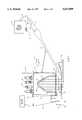
- FIG. 1is a schematic diagram of an apparatus embodying various features of the present invention for removing a coating or contaminant from a substrate by ablating the coating or contaminant from the surface of the substrate and impinging the surface with a stream of carbon dioxide.
- FIG. 2is a front, cross-sectional, elevation view of the housing in which the light source and reflector are mounted.
- FIG. 3is a side, cross-sectional, elevation view of the flashlamp mounted in the housing.
- FIG. 4illustrates the target area of the light source and the footprint of the carbon dioxide stream on the surface of the structure.
- FIG. 5shows the outlet of the nozzle through which the carbon dioxide stream is ejected.
- FIG. 6shows a cross-sectional view of the liquid carbon dioxide processing chamber where the liquid carbon dioxide source transitions to carbon dioxide gas and/or carbon dioxide snow suitable for use as a cleaning and cooling agent.
- FIG. 7is a block diagram of an embodiment of a system embodying various features of the present invention that employs a central control processor used to control certain parameters affecting the removal of the coating or contaminant.
- FIG. 8is a schematic diagram of another embodiment of a system embodying various features of the present invention which includes optical or acoustic feed back to control the removal of the coating.
- System 10includes a housing 12 in which is mounted a radiant energy source such as an optical energy source 14 and a reflector 16 such that optical energy (shown as arrows 18) generated by the optical energy source 14 is directed and/or reflected off of a reflective surface 19 through a window 20 so as to irradiate a target area on the surface 23 of a structure 22.
- the structure 22is comprised of substrate 28 on which is formed layers 26 and 24.
- the structure 22may include any number of layers, for purposes of illustration, the structure is described herein as having two layers 24 and 26.
- the optical energy source 14 and reflector 16are preferably cooled by deionized water provided from a water supply (not shown) to interior of housing 12 through inlet tube 58 and returned through outlet tube 59.
- Housing 12is supported by manipulator 29 which may be controlled to move housing 12 over the surface 23 of structure 22 at a standoff distance, d, in order to irradiate and scan the structure with optical energy generated by optical energy source 14.
- Standoff distance drepresents the perpendicular distance between window 20 and the top surface 23 of structure 22.
- a CIMROC 4000 Robot Controller manufactured by CIMCORP Precision Systems, Inc., Shoreview, Minn.is an example of a suitable manipulator 29.
- the optical energy source 14may be a broadband flashlamp.
- the output of a broadband flashlampoffers the advantage of providing a wide variety of electromagnetic spectrum components, enhancing the probability that some of the components will be absorbed by a wide variety of different materials.
- a flashlampoffers the further advantage of being readily adaptable for irradiating relatively large areas at the same time.
- the optical energy source 14irradiates a target area on the surface 23 of the structure 22 whereby the coating material irradiated by light energy absorbs the light energy in the form of heat. If the optical power intensity at the irradiated surface 23 of the material is sufficient, the material vaporizes, or is ablated.
- the ablation mode of many coatingsoccurs as a two step process. First, the coating is pyrolyzed which involves the breaking of chemical bonds within the coating. This results in reduced adhesion of the coating to the underlying substrate. Second, the smaller molecules remaining from the pyrolysis are subsequently individually ablated or burned producing even smaller molecules of primarily CO 2 , H 2 O and other combustion by-products. Hence, the ablation process is the rapid decomposition and vaporization of a material resulting from the absorption of energy by the material. Continued irradiation causes continued ablation, and hence removal of the irradiated coating material from the underlying structure.
- the intensity of light energy 18 incident on structure 22must be sufficient so that in response to being irradiated, layers 24 and 26 absorb enough light energy 18 that is converted to heat such that the layers 24 and 26 ablate or at least pyrolyze.
- the degree of ablation and/or pyrolysis of the layers 24 and 26 as a result of a single optical pulseis determined by the pulse width of optical energy source 14, the thickness of the layers, and the thermal characteristics of the materials comprising the structure.
- the embodiment of the inventionfurther includes a stream of carbon dioxide 31 mixed with air which is ejected from a nozzle 32 and directed toward the target area of the substrate 28 so as to drive away the vapors of any removed layers from the substrate 28 while simultaneously cleaning and cooling the substrate 28. Removing the vapors from around the target area that result from the ablation/pyrolysis of the material essentially prevents the vapors from depositing on the window of the flashlamp or other optical components of the system.
- the carbon dioxide stream 31is provided to the nozzle 32 via an expansion chamber 34 from a liquid carbon dioxide source 35 that is appropriately mixed with air.
- the expansion chamber 34is adapted to receive the liquid carbon dioxide where it is mixed with an air stream. Within the expansion chamber, the liquid carbon dioxide undergoes phase transition into low temperature carbon dioxide gas and low temperature carbon dioxide snow. The combination of carbon dioxide snow and carbon dioxide gas and air exits the expansion chamber via a nozzle 32 whereby it forms a low kinetic energy stream of carbon dioxide snow entrained in a gas.
- the nozzle 32is adapted for directing the combination of gas and carbon dioxide snow at the target area of the substrate 28.
- Nozzle 32is mounted to housing 12 so that as the housing 12 is translated, optical energy source 14 is moved to scan different target areas of structure 22 with nozzle 32 following.
- the structure 22is subjected to a continuous process whereby optical energy source 14 scans structure 22 to irradiate and pyrolyze/ablate selected regions of the structure 22 while carbon dioxide stream 31 disperses or drives away the material.
- carbon dioxide stream 31As the carbon dioxide stream 31 impinges the surface 30 of the substrate 28, it provides a means for controlling the temperature of, i.e. cooling, the surface 30 of the substrate 28 so that it does not become hot enough to sustain heat damage.
- the carbon dioxide stream 31is also particularly adapted for removing various contaminants and cleaning the exposed surface 30 of the substrate 28 while simultaneously preventing material debris and vapors from depositing on the flashlamp system.
- the inventionis controlled with the use of a central control processor which is adapted for controlling, among other things, the rate of liquid carbon dioxide introduced into the expansion chamber, the phase transition of the liquid carbon dioxide, the velocity of the carbon dioxide gas and carbon dioxide snow exiting the nozzle and impinging the target area, and the frequency, magnitude and pulse width of the radiant energy source.
- the method of control used with the present inventioncan further include: photodetecting systems which are adapted for detecting various optical characteristics of the surface of the structure; photoacoustic systems which are adapted for detecting the photoacoustic signature signals form the surface of the structure; or video control systems which are adapted for recording and displaying the visual characteristics to allow an operator to manually control the operating characteristics of the system.
- vacuum system 37draws the ablated and pyrolyzed material (shown as arrow 38) away from the irradiation site through nozzle 39.
- Such vacuum systemsare well known in the art.
- the incident intensity of light energy 18must be great enough to initiate the ablation/pyrolysis of substantial amounts of layers 24 and 26 at the target area.
- the incident intensity of light energy 18should generally be in the range of about 18-25 joules/cm 2 at a full-width, half-maximum (FWHM) pulse, between about 1000-2000 microseconds and typically 1700 microseconds, and time to peak of about 1 millisecond.
- FWHMfull-width, half-maximum
- Alternative embodimentscontemplate using different repetition rates and pulse widths.
- the scope of the present embodiment of the inventionincludes utilization of incidence intensities ranging anywhere up to 30 joules/cm 2 .
- Control of the intensity of radiant energy incident on the surface 23 of structure 22is easily effected primarily by employing an optical energy source 14 having a suitable output, and secondarily by establishing a suitable standoff distance d between the surface 23 of the structure 22 and the source of optical energy 14 at a scan rate that may typically be about 2.54 cm/second.
- a preferred system for removing contaminants and coatings from a substrate 10preferably includes broadband xenon flashlamp 14 mounted in housing 12.
- Broadband optical energygenerally refers to optical energy that includes spectral components with wavelengths that may range from 170 nm to 5000 nm.
- a flashlamp or flashtubeis a gas filled device which converts electrical energy to optical energy by passing current through a plasma typically contained in a transparent tube through which the optical energy is transmitted.
- Housing 12include upper housing 50 attached to lower housing 52 by fasteners 54.
- Reflector 16is mounted in lower housing 52 so that portions of light generated by flashlamp 14 are reflected out of housing 12 through quartz window 20.
- Housing 12may be fabricated from black, hard anodized aluminum.
- Gasket 56is interposed between upper and lower housings 50 and 52 to keep moist air from penetrating chamber 51 in upper housing 50.
- Electrical connectors 67 at the ends of optical energy source 14are supported in and extend through apertures 62 in walls 63 of lower housing 52.
- Flashlamp 14is positioned within fused quartz water jacket 61 mounted between walls 60 of lower housing 52. The position of flashlamp 14 is maintained by "O"-ring compression fittings 46 that fit over electrical connectors 67, and are fastened to walls 63 by threaded fasteners, not shown.
- "O"-rings 59 interposed between compression fittings 46 and walls 63provided a water tight seal therebetween.
- reflector 16may have an elliptical cross-section as shown in FIG.
- the longitudinal axis of flashlamp 14is generally coincident with a focus of reflector 16.
- the cross-section of reflector 516may be shaped in a variety of ways, preferably for example, as a keyhole or cusp.
- access to flashlamp 14is obtained through removable access plates 70 and 72 releasably mounted to lower housing 52 by means, not shown, as would be known by those skilled in the art.
- "O"-ring 71provides a watertight seal between access plate 70 and lower housing 52.
- "O"-ring 73provides a watertight seal between access plate 72 and lower housing 52.
- Electrical power to energize flashlamp 14is conventionally provided by high voltage coaxial cable 79 that penetrates upper housing 50 through cable fitting 68 and includes center conductor 66a and braided conductor strap 66b.
- Center conductor 66is conventionally connected to high voltage terminal post 69a with a lug 65a soldered or brazed to the center conductor.
- Terminal post 69ais electrically connected to flashlamp 14 via braided cable 75a brazed to high voltage electrical connector 67.
- Electrical returnis provided by braided cable 75b brazed or soldered to low voltage electrical connector 67 and to terminal post 69b.
- the end of braided conductor strap 66bis terminated with lug 65b which is connected to terminal post 69b.
- Flashlamp 14may be removed from lower housing 52 as follows: First, electrical power must be disconnected from housing 12. Then, quick connect fittings 55 are disconnected from inlet and outlet tubes 58 and 59, respectively. Fasteners 54 are removed from stantions 57 connected to lower housing 52 so that the lower housing may be separated from upper housing 50. Then, access plates 70 and 72 are removed from lower housing 52. Braided cables 75a and 75b are unbolted from terminal posts 69a and 69b, respectively. Compression fittings 46 are unfastened from walls 63 and slipped out over their respective braided cables 75a and 75b. Then, flashlamp 14 may be carefully slipped out of water jacket 61 through either of apertures 62 and out of lower housing 52. Replacement of flashlamp 14 is accomplished by performing in reverse order, the steps recited above for removing the flashlamp.
- Window 20is preferably manufactured of fused quartz or other synthetic materials that have excellent transparency and high resistance to heat. Further, the transparency of the window should not degrade from exposure to ultraviolet light.
- Gasket 81is interposed between window 20 and window frame 80 so that the window 20 is held in a watertight arrangement to lower housing 52 by bolts 82.
- Flashlamp 14 and reflector 16are preferably cooled with deionized water having a temperature, for example, of about 50° F. supplied at a rate of about 2 gallons per minute from a water supply (not shown) to housing 12 through inlet tube 58 and returned through outlet tube 59.
- the deionized waterpreferably has an electrical resistance of at least 1 megohm.
- Inlet tube 58penetrates upper housing 50 and is connected to manifold 74, mounted in lower housing 52, having multiple outlets 76 which penetrate reflector cavity 64 to distribute water over the length of flashlamp 14 and fill the reflector cavity 64. Water also penetrates the tapered ends 88 of quartz water jacket 61 to cool electrical connectors 67 and flashlamp 14. Heat resulting from the generation of radiant energy from flashlamp 14 is absorbed by the water and transported out of chamber 64 through port 78 in fluid communication with outlet tube 59.
- the operation of the flashlampshould be critically damped, that is, it should be operated with a dampening coefficient of about 0.77.
- Factors that determine the dampening coefficient of a flashlampinclude: inductance of a single mesh pulse forming network ("PFN") typically employed in a flashlamp power circuit, capacitance, C, of the PFN, arc length of the flashlamp, and operating voltage, V, across the terminals of the flashlamp.
- Vshould only be varied by no more than about ⁇ 5 per cent of the optimum voltage in order to maximize service life.
- a flashlampmay be configured as having a tube filled with xenon gas at a pressure of 450 Torr, a bore of about 17 mm, and an arc length of about 12 inches.
- Typical pulse lengths for a xenon flash lampare between 1 ⁇ sec and 5 msec.
- the energy required for this system for a given coating on a given substratecan be readily empirically determined.
- This particular flashlampis preferably operated at a repetition rate of 4-6 Hz with a FWHM fixed pulse width of about 1700 microseconds and an input energy of about 200 joules/cm of arc length, although in some circumstances it might be desirable to have a greater repetition rate and a shorter pulse width.
- the useful output energy of a flashlamp available to irradiate the surface 23 of structure 22is approximately 20-25 per cent of the input energy to the flashlamp.
- the flashlampis powered by a suitable power supply, not shown, as would be known by those of ordinary skill in the art.
- the preferred method of controlling the energy flux (joules/second) at the surface 23 of structure 22is to establish an appropriate distance between the flashlamp 14 and the surface 23 of the structure 22 since the incident energy intensity at the surface 23 of the structure 22 is generally inversely proportional to the distance between the surface and the flashlamp 14.
- the distance between the flashlamp 14 and the surface 23 of structure 22is more conveniently discussed with reference to the standoff distance, d, between the surface 23 of structure 22 and window 20, since the window 20 and the flashlamp 14 are a fixed distance apart.
- the temperature of layers 24 and 26are a function of the optical energy output of flashlamp 14 that is absorbed by the layers 24 and 26, the repetition rate of the flashlamp (or of any other radiant energy source), the albedo of the surface of layer 26 (the "surface” layer) the relative speed (also referred to as the scan rate) between flashlamp 14 and structure 22, the distance between flashlamp 14 and the surface 23 of structure 22, the temperature of carbon dioxide stream 31, and the mass flow rate of the carbon dioxide stream 31.
- the flashlamp 14is preferably operated at a constant repetition rate.
- the present inventionadvantageously allows varying the temperature and mass flow rate of carbon dioxide stream 31 to control the temperature of layers 24 and 26.
- the temperature of layers 24 and 26, as well as the temperature of substrate 28,may be controlled by varying the mass flow rate of carbon dioxide stream 31 because the carbon dioxide stream 31 absorbs heat energy from substrate 22.
- the mass flow rate of carbon dioxide stream 31may be increased.
- a suitable scan speed and standoff distanceare determined experimentally.
- a structureis scanned at an initial trial scan speed using the system and methods described with reference to FIG. 1.
- the initial trial speed at which the surface of structure 22 is scannedis intentionally controlled to be high enough so that at a given intensity of optical energy at the surface of structure 22, an insufficient amount of layers 24 and 26 are removed.
- the high scan speedavoids damaging substrate 28 by preventing too much optical energy from being absorbed by structure 22.
- the scan speedis decreased until, at a given incident intensity determined by the standoff distance, sufficient material is removed from layers 24 and 26 so as to exposed the surface of substrate 28 in undamaged condition.
- the standoff distance, dis controlled to provide an incident intensity at the surface 23 of structure 22 that may be in the range of 18-25 joules/cm 2 . If the surface 30 of substrate 28 is damaged, a faster scan speed may be tried. The maximum scan speed is limited by the performance characteristics of manipulator 29. If substrate 28 is damaged at the fastest reasonable scan speed of manipulator 29, then the standoff distance, d, should be increased.
- the inventionmay be operated where the incidence intensity at the surface 23 of structure 22 is about 18-25 joules/cm 2 with a scan speed that may range from about 2.54-3.0 cm/second.
- manipulator 29is positioned so that the standoff distance, d, between window 20 and the surface 23 of structure 22 is such that the radiant energy flux provided by optical energy 18 at the surface 23 of structure 22 is sufficient to initiate the ablation and/or pyrolysis of the layers 24 and 26.
- Manipulator 29is controlled to locate housing 12 such that optical energy source 14 is positioned over the area of structure 22 from which layers 24 and 26 are to be removed.
- Deionized watercirculates through housing 12 to cool reflector 16 and optical energy source 14.
- the optical energy source 14is then enabled and directed to irradiate and scan the surface of structure 22.
- the carbon dioxide stream 31is directed to impinge the surface of structure 22 and the vacuum system 37 is enabled to collect and remove the material 38 and expended carbon dioxide stream 31 from the target area.
- Pulsed optical energy 18 incident on the target area of the surface 23 of structure 22is absorbed and converted to heat, causing layers 24 and 26 to ablate. Exposure of additional areas of substrate 28 is accomplished by moving housing 12 so that optical energy source 14 scans structure 22 in the direction of arrow 21. During this time, the carbon dioxide stream 31 is directed to impinge the ablated/pyrolyzed region of layers 24 and 26. The carbon dioxide stream 31 is directed to impinge the structure 22 to clean and cool the surface 30 of substrate 22 while simultaneously dispersing the remains of the layers 24 and 26 thereby preventing any residual debris or vapors from depositing on the optical components (i.e. window) of the system 10.
- the vacuum system 37continuously draws the material 38 and expended carbon dioxide stream 31 through vacuum nozzle 36 to collect and remove them from the vicinity of the target area at the surface of structure 22. Because the carbon dioxide stream 31 is directed to impinge the surface of structure 22 at an angle, ⁇ , the remains of layers 24 and 26 and carbon dioxide stream 31 are ultimately dispersed towards the vacuum nozzle.
- Optical energy source 14is directed to scan structure 22 until a sufficient area of substrate 28 has been exposed and cleaned, at which time the system 10 may be shut down.
- Area 94includes a focus or "target" area 96, having a width, W L , that is subjected to the more intense irradiation and is surrounded by penumbra area 98 which is subjected to less intense irradiation.
- W La width
- penumbra area 98which is subjected to less intense irradiation.
- Area 96has a "leading" edge 99 and a "trailing" edge 100.
- area 96is shown to be substantially rectangular. However, the shape of area 96 depends on the particular configuration of reflector, which may be selected to suit the requirements of a specific application.
- carbon dioxide stream 31(not shown in FIG. 4) is directed to and impinges the surface 23 in the direction of arrow 21 with a pattern or footprint 102 that is determined by the shape of the outlet 103 of nozzle 32, shown in FIG. 5.
- the surface of structure 22 intended to be irradiated by optical energy sourcemay be referred to as a "target area.”
- footprint 102having a trailing edge 106, overlies a portion of area 96 such that the leading edge 104 of footprint 102 is just slightly ahead of the trailing edge 100 of area 96 in order to assure that carbon dioxide stream impinges affected regions of layers 24 and 26.
- the optical energy source and carbon dioxide streammay overlap the target area at the same time.
- leading edge 104 of footprint 102 of carbon dioxide streammay also impinge behind the affected regions of layers 24 and 26 provided that the region impinged by carbon dioxide stream is in an ablated state.
- the target areais first irradiated by optical energy source, and then momentarily later, is impinged by carbon dioxide stream which results in the removal of layers 24 and 26 to expose some of the surface 30 and preventing the debris or vapors from depositing on the window of the flashlamp.
- the shape of footprint 93is determined by the shape of outlet 103 of nozzle 32 and the angle, ⁇ , between the flow axis 108 of nozzle 32 and the surface 30 of substrate 28, as seen in FIG. 1.
- the shape of outlet 103may be an elongated rectangle, as shown, in FIG. 5 or oval.
- FIG. 6shows a cross-sectional view of the liquid carbon dioxide processing subsystem 33 where the liquid carbon dioxide source 35 undergoes phase transition to carbon dioxide gas and/or carbon dioxide snow.
- the liquid carbon dioxide processing subsystem 33preferably comprises a liquid carbon dioxide source 35; a liquid carbon dioxide injection tube 41; an injection valve or orifice 42 adapted to control the rate of liquid carbon dioxide injection; an air inlet port 43; and an expansion chamber 34.
- the expansion chamber 34is an enclosed chamber of a predetermined volume adapted to receive the liquid carbon dioxide source 35 where the liquid carbon dioxide expands under controlled conditions to form low temperature carbon dioxide gas and low temperature carbon dioxide snow.
- the phase transitioning of the liquid carbon dioxide source 35is controlled in part by the rate at which the liquid carbon dioxide source 35 is injected into the expansion chamber 34, the volume of the expansion chamber 34, and the air introduced into the expansion chamber 34.
- the carbon dioxide gas and/or carbon dioxide snoware directed to the nozzle 32.
- the nozzle 32is adapted for directing the combination of carbon dioxide gas and carbon dioxide snow at the target area of the structure.
- the carbon dioxide streamwhich consists of carbon dioxide snow within a gas stream provides an enhanced cooling effect of substrate 28 as compared to pelletized carbon dioxide attributable to the increased effective surface area of the low temperature carbon dioxide.
- the second embodimentalso provides a benign process and system for removing coatings from a substrate without damaging the substrate.
- the second embodimentfurther features a digital data processor which coordinates and controls the scan rate of optical energy and carbon dioxide stream across the surface of substrate. Control is effected using feedback provided by a detecting device such as an optical detecting circuit that detects the optical character of the surface of structure.
- the central control processorgenerates a signal 202 which enables the liquid carbon dioxide source 35 and is further adapted to control certain parameters of the liquid carbon dioxide subsystem 33. In this manner, the mass flow rate of the carbon dioxide stream, the temperature of the carbon dioxide stream, and the physical composition of the carbon dioxide stream are controlled.
- the central control processor 200also generates a signal 206 which enables the vacuum system 37.
- the central control processor 200generates a signal 208 adapted to control the output of the optical light source 14 by means of a light control circuit 210.
- Light control circuit 210generates a control signal 216 which establish the repetition rate and pulse width of the output of optical energy source 14 depending on the substrate surface and the coating materials that require removal.
- the central control processor 200also furnishes an output signal 212 which provides path and speed instructions to robotics controller 214.
- Robotics controller 214transforms signal 212 into control signals 218, 220 that direct the path and speed of robotics positioner 29.
- the path of robotics controller 214is determined in accordance with a suitable path-generating processing routine that is implemented by the central control processor 200 in accordance with techniques well known by those skilled in the art.
- the central control processor 200may be an IBM AT or AT compatible personal computer. As discussed above, the central control processor 200 may receive feedback data 228 from a detecting device 45 as well as a signal 232 from the robotics controller. Specifically, the feedback data may be collected from photodetecting systems, photoacoustic systems, or video control systems. Photodetecting systems are adapted for detecting various optical characteristics of the surface of the structure and/or the substrate. Photoacoustic systems, on the other hand, are adapted for detecting the photoacoustic signature signals from the surface of the structure or substrate. Signals corresponding to these optical or acoustic characteristics are fed into the central control processor. Various photodetecting systems and photoacoustic detection systems are discussed in detail in U.S. Pat. Nos. 5,194,723, 5,204,517, and 5,328,517, incorporated herein by reference.
- An alternative control systeminvolves the use of various video control systems which are adapted for recording and displaying the visual characteristics to allow an operator to manually control the operating characteristics of the system in real time by an operator using visual feedback based on observation of the trail of exposed surface.
- visual feedbackmay, for example, be provided by direct observation, or by a television system, not shown. If the operator observes that insufficient material is being removed at a particular region, the scan speed may be decreased, the standoff distance, d, may be reduced, or the carbon dioxide stream may be varied by the operator.
- housing 12optical energy source 14 and reflector 16, as described above with regard to the first embodiment and as represented by FIG. 1.
- Housing 12is supported by robotics positioner or manipulator 29 at a predetermined standoff distance from the surface 23 of structure 22. The standoff distance is determined as described further herein.
- Robotics positioner or manipulator 29is controlled to move housing 12 along a predetermined path at a controlled scan speed over the surface 23 of structure 22 so that optical energy source 14 and carbon dioxide stream 31 may be directed to scan and impinge, respectively, the coating or coatings formed on the surface 30 of substrate 28.
- Material removed from the surface 30 of substrate 28 and the expended carbon dioxide stream 30 after it impinges structure 22are collected by vacuum system 37 through nozzle 39 mounted to housing 12.
- a detecting device 45is mounted to housing 12 by means not shown and detects the predetermined physical, acoustic or optical characteristics of the surface 23 of structure 22 and substrate 28 and generates an output signal which is subsequently fed back to the central control processor (See FIG. 7).
- the carbon dioxide stream or "snow”manages the temperature and cleaning of the painted substrate by varying the carbon dioxide pressure and air mixture flow rate.
- the carbon dioxide pressure and orifice size, or flow opening to the nozzledictate the liquid carbon dioxide flow rate, or amount of "snow” deposited onto the painted surface. This flow rate controls the cooling level required to maintain an acceptable surface operating temperature.
- the carbon dioxide pressureis operated from the computer via an electric control valve, enabling real time adjustment.
- the carbon dioxide streamessentially prevents the depositing and accumulation of vapors on the window of the system as well as contributes to the cleaning of the substrate. Both of these aspects are controlled by varying the flow rate of the air mixed with the carbon dioxide. This operation is again controlled via an electrical control valve operated from the main control computer.
- the inventorwould envision a video camera which would monitor the surface soot deposits, such as a color sensor, in-turn varying the air flow rate.
- the present carbon dioxide control systemis operated in a manual fashion, but would be upgraded to automatic operation, as described above, for a turn-key system.
- the pulsed power modulator or lamp power sourceis preferably operated between about 2000 and 2300 volts at an operating frequency of 4 Hz or 4 pulses per second. These electrical characteristics result in an average operating power of 18 to 24 kW.
- the lamp and reflector assemblyare moved across the paint surface at a velocity of about 1 to 1.2 inches per second, maintaining a stand-off distance of about 1.5 to 1.8 inches.
- the carbon dioxide pressureis maintained between about 250 and 270 psi through a 1/8 inch orifice resulting in a flow rate between about 2.4 and 2.7 gallons per minute.
- the carbon dioxideis mixed with air, flowing at about 220 cubic feet per minute, at the nozzle resulting in a pressurized carbon dioxide stream of carbon dioxide gas and snow to the paint surface.
- Liquid carbon dioxide at high pressureis transported from a storage vessel. There is a slight pressure drop in the liquid carbon dioxide as the liquid carbon dioxide flows along the conduit and injection tube connecting the storage vessel and orifice. The liquid carbon dioxide is then expanded through the orifice which is located at the end of the liquid carbon dioxide injection tube. As the liquid carbon dioxide passes into the expansion chamber it flashes or changes phase into solid carbon dioxide snow and gaseous carbon dioxide. The preferred ratio is approximately 55% carbon dioxide snow and 45% carbon dioxide gas.
- the phase transitionoccurs immediately upon the expansion and corresponding reduction in pressure, preferably yielding a carbon dioxide gas/snow mixture at approximately -80° C. and approximately 1 atmosphere of pressure. Ideally, the expansion and phase transition occurs at a constant enthalpy.
- the orificesupports the pressure drop between the liquid carbon dioxide in the injection tube and the approximately 1 atmosphere of pressure in the expansion chamber.
- Operation under the aforementioned conditionswould remove between 1 and 4 mils of paint from a painted aluminum or composite substrate.
- the amount of material removeddepends on many variables including the color and reflection coefficient (i.e. reflectivity) of the material to be removed.
- the carbon dioxide streamimpinges the painted surface 1 to 2 inches behind the optical footprint at an angle between 20 and 40 degrees.
- the carbon dioxide streamkeeps the painted substrate at an acceptable temperature level. The actual temperature is dictated by the application in which the system is used and can be controlled by adjusting the carbon dioxide operating parameters.
- the carbon dioxide streamfurther cleans the surface following the ablation and/or pyrolysis process and prevents the ablated material from depositing on the equipment.
Landscapes
- Engineering & Computer Science (AREA)
- Physics & Mathematics (AREA)
- Optics & Photonics (AREA)
- Mechanical Engineering (AREA)
- Plasma & Fusion (AREA)
- Cleaning In General (AREA)
Abstract
Description
Claims (12)
Priority Applications (1)
| Application Number | Priority Date | Filing Date | Title |
|---|---|---|---|
| US08/460,732US5613509A (en) | 1991-12-24 | 1995-06-02 | Method and apparatus for removing contaminants and coatings from a substrate using pulsed radiant energy and liquid carbon dioxide |
Applications Claiming Priority (4)
| Application Number | Priority Date | Filing Date | Title |
|---|---|---|---|
| US07/813,872US5328517A (en) | 1991-12-24 | 1991-12-24 | Method and system for removing a coating from a substrate using radiant energy and a particle stream |
| CA002112606ACA2112606A1 (en) | 1991-12-24 | 1993-12-30 | Method and system for removing a coating from a substrate using radiant energy and a particle stream |
| US08/204,852US5782253A (en) | 1991-12-24 | 1994-03-02 | System for removing a coating from a substrate |
| US08/460,732US5613509A (en) | 1991-12-24 | 1995-06-02 | Method and apparatus for removing contaminants and coatings from a substrate using pulsed radiant energy and liquid carbon dioxide |
Related Parent Applications (1)
| Application Number | Title | Priority Date | Filing Date |
|---|---|---|---|
| US08/204,852Continuation-In-PartUS5782253A (en) | 1991-12-24 | 1994-03-02 | System for removing a coating from a substrate |
Publications (1)
| Publication Number | Publication Date |
|---|---|
| US5613509Atrue US5613509A (en) | 1997-03-25 |
Family
ID=27169675
Family Applications (1)
| Application Number | Title | Priority Date | Filing Date |
|---|---|---|---|
| US08/460,732Expired - Fee RelatedUS5613509A (en) | 1991-12-24 | 1995-06-02 | Method and apparatus for removing contaminants and coatings from a substrate using pulsed radiant energy and liquid carbon dioxide |
Country Status (1)
| Country | Link |
|---|---|
| US (1) | US5613509A (en) |
Cited By (35)
| Publication number | Priority date | Publication date | Assignee | Title |
|---|---|---|---|---|
| US5775127A (en)* | 1997-05-23 | 1998-07-07 | Zito; Richard R. | High dispersion carbon dioxide snow apparatus |
| DE19807635A1 (en)* | 1998-02-23 | 1999-08-26 | Air Liquide Gmbh | Procedure for removing bituminous and other adhering layers of impurities from wall surfaces |
| US6028316A (en)* | 1996-08-28 | 2000-02-22 | New Star Lasers, Inc. | Method and apparatus for removal of material utilizing near-blackbody radiator means |
| US6029681A (en)* | 1995-09-26 | 2000-02-29 | Hermetic Hydraulik Ab | Device for de-scaling semi-finished products |
| US6048369A (en)* | 1998-06-03 | 2000-04-11 | North Carolina State University | Method of dyeing hydrophobic textile fibers with colorant materials in supercritical fluid carbon dioxide |
| US6066032A (en)* | 1997-05-02 | 2000-05-23 | Eco Snow Systems, Inc. | Wafer cleaning using a laser and carbon dioxide snow |
| US6261326B1 (en) | 2000-01-13 | 2001-07-17 | North Carolina State University | Method for introducing dyes and other chemicals into a textile treatment system |
| US6347976B1 (en)* | 1999-11-30 | 2002-02-19 | The Boeing Company | Coating removal system having a solid particle nozzle with a detector for detecting particle flow and associated method |
| US20030010435A1 (en)* | 1998-11-04 | 2003-01-16 | Xenon Corporation | Spiral-shaped lamp for UV curing of coatings and bonding for a digital versatile disk (DVD) or compact disk ( CD) |
| WO2003044805A1 (en) | 2001-11-23 | 2003-05-30 | Korea Atomic Energy Research Institute | Method and device for collecting particulate contaminants during co2 blasting decontamination |
| KR100389015B1 (en)* | 2001-02-19 | 2003-06-25 | 한국전력공사 | CO2 snow decontamination equipments |
| US6676710B2 (en) | 2000-10-18 | 2004-01-13 | North Carolina State University | Process for treating textile substrates |
| US6701942B2 (en)* | 2001-03-28 | 2004-03-09 | Samsung Electronics Co., Ltd. | Method of and apparatus for removing contaminants from surface of a substrate |
| US6724134B1 (en)* | 2002-03-26 | 2004-04-20 | Phoenix Science And Technology, Inc. | Surface discharge lamp and system |
| US20050150878A1 (en)* | 2004-01-09 | 2005-07-14 | General Lasertronics Corporation | Color sensing for laser decoating |
| US20060042659A1 (en)* | 2004-09-01 | 2006-03-02 | Pinnacle West Capital Corporation | Robotic system and method for circumferential work processes and delivery of a medium |
| US20070000885A1 (en)* | 2004-01-09 | 2007-01-04 | General Lasertronics Corporation | Color sensing for laser decoating |
| WO2007106608A3 (en)* | 2006-01-18 | 2007-12-21 | Univ Northern Iowa Res Foundat | Light beam targeting and positioning system for a paint or coating removal blasting system |
| US20090007933A1 (en)* | 2007-03-22 | 2009-01-08 | Thomas James W | Methods for stripping and modifying surfaces with laser-induced ablation |
| US20090008827A1 (en)* | 2007-07-05 | 2009-01-08 | General Lasertronics Corporation, A Corporation Of The State Of California | Aperture adapters for laser-based coating removal end-effector |
| DE102009041798A1 (en)* | 2009-09-18 | 2011-03-24 | Khs Gmbh | Process for removing labels and soiling of all kinds |
| EP2305425A1 (en)* | 2009-10-05 | 2011-04-06 | Linde AG | Device for capturing material during dry ice blasting |
| EP2306467A1 (en)* | 2009-10-05 | 2011-04-06 | Linde Aktiengesellschaft | Method of capturing material during dry ice blasting |
| US8466434B2 (en) | 2010-11-02 | 2013-06-18 | Goodrich Corporation | Aircraft potable water system |
| US20160244871A1 (en)* | 2015-02-25 | 2016-08-25 | Fei Company | Multi-source gis for particle-optical apparatus |
| US9532693B1 (en)* | 2008-05-29 | 2017-01-03 | Bissell Homecare, Inc. | Unattended spot cleaning with surface sanitization |
| US9895771B2 (en)* | 2012-02-28 | 2018-02-20 | General Lasertronics Corporation | Laser ablation for the environmentally beneficial removal of surface coatings |
| US20180141164A1 (en)* | 2016-11-23 | 2018-05-24 | SLCR-Lasertechnik GmbH | Coating removal method |
| US20180269080A1 (en)* | 2017-03-17 | 2018-09-20 | Tel Fsi, Inc. | System and method for monitoring treatment of microelectronic substrates with fluid sprays such as cryogenic fluid sprays |
| US10086597B2 (en) | 2014-01-21 | 2018-10-02 | General Lasertronics Corporation | Laser film debonding method |
| US10112257B1 (en) | 2010-07-09 | 2018-10-30 | General Lasertronics Corporation | Coating ablating apparatus with coating removal detection |
| WO2020123529A1 (en)* | 2018-12-10 | 2020-06-18 | Molekule Inc. | System and method for coating removal |
| US11162031B2 (en)* | 2018-02-16 | 2021-11-02 | Paolo Peri | Method for the pyrolysis of raw materials, in particular raw materials deriving from tires or bitumen and pyrolysis equipment operating according to said method |
| US11235359B2 (en)* | 2019-02-11 | 2022-02-01 | The Boeing Company | Robotic laser and vacuum cleaning for environmental gains |
| US11317517B2 (en)* | 2020-06-12 | 2022-04-26 | PulseForge Incorporated | Method for connecting surface-mount electronic components to a circuit board |
Citations (36)
| Publication number | Priority date | Publication date | Assignee | Title |
|---|---|---|---|---|
| US3700850A (en)* | 1970-09-04 | 1972-10-24 | Western Electric Co | Method for detecting the amount of material removed by a laser |
| US3986391A (en)* | 1975-09-22 | 1976-10-19 | Western Electric Company, Inc. | Method and apparatus for the real-time monitoring of a continuous weld using stress-wave emission techniques |
| US4114018A (en)* | 1976-09-30 | 1978-09-12 | Lasag Ag | Method for ablating metal workpieces with laser radiation |
| US4249956A (en)* | 1979-08-01 | 1981-02-10 | Hartman Charles N | Method of removing paint from a brick surface |
| US4398961A (en)* | 1980-12-01 | 1983-08-16 | Mason Richard R | Method for removing paint with air stream heated by hot gas |
| US4419562A (en)* | 1982-01-19 | 1983-12-06 | Western Electric Co., Inc. | Nondestructive real-time method for monitoring the quality of a weld |
| US4491484A (en)* | 1981-11-24 | 1985-01-01 | Mobile Companies, Inc. | Cryogenic cleaning process |
| US4504727A (en)* | 1982-12-30 | 1985-03-12 | International Business Machines Corporation | Laser drilling system utilizing photoacoustic feedback |
| US4543486A (en)* | 1983-05-20 | 1985-09-24 | The United States Of America As Represented By The Secretary Of The Army | Method and apparatus for using a photoacoustic effect for controlling various processes utilizing laser and ion beams, and the like |
| US4582540A (en)* | 1983-05-03 | 1986-04-15 | Utvecklings Ab Carmen | Method for removing glazing putty from windows |
| US4588885A (en)* | 1984-02-07 | 1986-05-13 | International Technical Associates | Method of and apparatus for the removal of paint and the like from a substrate |
| US4631250A (en)* | 1985-03-13 | 1986-12-23 | Research Development Corporation Of Japan | Process for removing covering film and apparatus therefor |
| US4655847A (en)* | 1983-09-01 | 1987-04-07 | Tsuyoshi Ichinoseki | Cleaning method |
| US4682594A (en)* | 1985-03-11 | 1987-07-28 | Mcm Laboratories, Inc. | Probe-and-fire lasers |
| US4693756A (en)* | 1984-07-17 | 1987-09-15 | Schlick Roto-Jet Maschinenbau Gmbh | Method and retort for the removal of carbonizable coatings from the surfaces of metal objects |
| US4718974A (en)* | 1987-01-09 | 1988-01-12 | Ultraphase Equipment, Inc. | Photoresist stripping apparatus using microwave pumped ultraviolet lamp |
| US4731125A (en)* | 1984-04-19 | 1988-03-15 | Carr Lawrence S | Media blast paint removal system |
| US4737628A (en)* | 1984-02-07 | 1988-04-12 | International Technical Associates | Method and system for controlled and selective removal of material |
| US4756765A (en)* | 1982-01-26 | 1988-07-12 | Avco Research Laboratory, Inc. | Laser removal of poor thermally-conductive materials |
| US4803021A (en)* | 1986-02-14 | 1989-02-07 | Amoco Corporation | Ultraviolet laser treating of molded surfaces |
| US4806171A (en)* | 1987-04-22 | 1989-02-21 | The Boc Group, Inc. | Apparatus and method for removing minute particles from a substrate |
| US4836858A (en)* | 1986-09-02 | 1989-06-06 | The United States Of America As Represented By The Secretary Of The Air Force | Ultrasonic assisted paint removal method |
| US4867796A (en)* | 1982-04-05 | 1989-09-19 | Maxwell Laboratories, Inc. | Photodecontamination of surfaces |
| WO1990013807A1 (en)* | 1989-05-09 | 1990-11-15 | Richard Joseph Weniger | Optical sensor for detecting quantity of protective coating |
| US4994639A (en)* | 1989-01-11 | 1991-02-19 | British Aerospace Public Limited Company | Methods of manufacture and surface treatment using laser radiation |
| US5013366A (en)* | 1988-12-07 | 1991-05-07 | Hughes Aircraft Company | Cleaning process using phase shifting of dense phase gases |
| US5024968A (en)* | 1988-07-08 | 1991-06-18 | Engelsberg Audrey C | Removal of surface contaminants by irradiation from a high-energy source |
| US5026964A (en)* | 1986-02-28 | 1991-06-25 | General Electric Company | Optical breakthrough sensor for laser drill |
| US5035750A (en)* | 1987-06-23 | 1991-07-30 | Taiyo Sanso Co., Ltd. | Processing method for semiconductor wafers |
| US5062898A (en)* | 1990-06-05 | 1991-11-05 | Air Products And Chemicals, Inc. | Surface cleaning using a cryogenic aerosol |
| US5194723A (en)* | 1991-12-24 | 1993-03-16 | Maxwell Laboratories, Inc. | Photoacoustic control of a pulsed light material removal process |
| US5204517A (en)* | 1991-12-24 | 1993-04-20 | Maxwell Laboratories, Inc. | Method and system for control of a material removal process using spectral emission discrimination |
| US5217925A (en)* | 1990-11-30 | 1993-06-08 | Taiyo Sanso Co., Ltd. | Apparatus and method for cleaning semiconductor wafers |
| US5225000A (en)* | 1990-11-02 | 1993-07-06 | Ebara Research Co., Ltd. | Method for cleaning closed spaces with ultraviolet rays |
| US5281798A (en)* | 1991-12-24 | 1994-01-25 | Maxwell Laboratories, Inc. | Method and system for selective removal of material coating from a substrate using a flashlamp |
| US5328517A (en)* | 1991-12-24 | 1994-07-12 | Mcdonnell Douglas Corporation | Method and system for removing a coating from a substrate using radiant energy and a particle stream |
- 1995
- 1995-06-02USUS08/460,732patent/US5613509A/ennot_activeExpired - Fee Related
Patent Citations (36)
| Publication number | Priority date | Publication date | Assignee | Title |
|---|---|---|---|---|
| US3700850A (en)* | 1970-09-04 | 1972-10-24 | Western Electric Co | Method for detecting the amount of material removed by a laser |
| US3986391A (en)* | 1975-09-22 | 1976-10-19 | Western Electric Company, Inc. | Method and apparatus for the real-time monitoring of a continuous weld using stress-wave emission techniques |
| US4114018A (en)* | 1976-09-30 | 1978-09-12 | Lasag Ag | Method for ablating metal workpieces with laser radiation |
| US4249956A (en)* | 1979-08-01 | 1981-02-10 | Hartman Charles N | Method of removing paint from a brick surface |
| US4398961A (en)* | 1980-12-01 | 1983-08-16 | Mason Richard R | Method for removing paint with air stream heated by hot gas |
| US4491484A (en)* | 1981-11-24 | 1985-01-01 | Mobile Companies, Inc. | Cryogenic cleaning process |
| US4419562A (en)* | 1982-01-19 | 1983-12-06 | Western Electric Co., Inc. | Nondestructive real-time method for monitoring the quality of a weld |
| US4756765A (en)* | 1982-01-26 | 1988-07-12 | Avco Research Laboratory, Inc. | Laser removal of poor thermally-conductive materials |
| US4867796A (en)* | 1982-04-05 | 1989-09-19 | Maxwell Laboratories, Inc. | Photodecontamination of surfaces |
| US4504727A (en)* | 1982-12-30 | 1985-03-12 | International Business Machines Corporation | Laser drilling system utilizing photoacoustic feedback |
| US4582540A (en)* | 1983-05-03 | 1986-04-15 | Utvecklings Ab Carmen | Method for removing glazing putty from windows |
| US4543486A (en)* | 1983-05-20 | 1985-09-24 | The United States Of America As Represented By The Secretary Of The Army | Method and apparatus for using a photoacoustic effect for controlling various processes utilizing laser and ion beams, and the like |
| US4655847A (en)* | 1983-09-01 | 1987-04-07 | Tsuyoshi Ichinoseki | Cleaning method |
| US4737628A (en)* | 1984-02-07 | 1988-04-12 | International Technical Associates | Method and system for controlled and selective removal of material |
| US4588885A (en)* | 1984-02-07 | 1986-05-13 | International Technical Associates | Method of and apparatus for the removal of paint and the like from a substrate |
| US4731125A (en)* | 1984-04-19 | 1988-03-15 | Carr Lawrence S | Media blast paint removal system |
| US4693756A (en)* | 1984-07-17 | 1987-09-15 | Schlick Roto-Jet Maschinenbau Gmbh | Method and retort for the removal of carbonizable coatings from the surfaces of metal objects |
| US4682594A (en)* | 1985-03-11 | 1987-07-28 | Mcm Laboratories, Inc. | Probe-and-fire lasers |
| US4631250A (en)* | 1985-03-13 | 1986-12-23 | Research Development Corporation Of Japan | Process for removing covering film and apparatus therefor |
| US4803021A (en)* | 1986-02-14 | 1989-02-07 | Amoco Corporation | Ultraviolet laser treating of molded surfaces |
| US5026964A (en)* | 1986-02-28 | 1991-06-25 | General Electric Company | Optical breakthrough sensor for laser drill |
| US4836858A (en)* | 1986-09-02 | 1989-06-06 | The United States Of America As Represented By The Secretary Of The Air Force | Ultrasonic assisted paint removal method |
| US4718974A (en)* | 1987-01-09 | 1988-01-12 | Ultraphase Equipment, Inc. | Photoresist stripping apparatus using microwave pumped ultraviolet lamp |
| US4806171A (en)* | 1987-04-22 | 1989-02-21 | The Boc Group, Inc. | Apparatus and method for removing minute particles from a substrate |
| US5035750A (en)* | 1987-06-23 | 1991-07-30 | Taiyo Sanso Co., Ltd. | Processing method for semiconductor wafers |
| US5024968A (en)* | 1988-07-08 | 1991-06-18 | Engelsberg Audrey C | Removal of surface contaminants by irradiation from a high-energy source |
| US5013366A (en)* | 1988-12-07 | 1991-05-07 | Hughes Aircraft Company | Cleaning process using phase shifting of dense phase gases |
| US4994639A (en)* | 1989-01-11 | 1991-02-19 | British Aerospace Public Limited Company | Methods of manufacture and surface treatment using laser radiation |
| WO1990013807A1 (en)* | 1989-05-09 | 1990-11-15 | Richard Joseph Weniger | Optical sensor for detecting quantity of protective coating |
| US5062898A (en)* | 1990-06-05 | 1991-11-05 | Air Products And Chemicals, Inc. | Surface cleaning using a cryogenic aerosol |
| US5225000A (en)* | 1990-11-02 | 1993-07-06 | Ebara Research Co., Ltd. | Method for cleaning closed spaces with ultraviolet rays |
| US5217925A (en)* | 1990-11-30 | 1993-06-08 | Taiyo Sanso Co., Ltd. | Apparatus and method for cleaning semiconductor wafers |
| US5194723A (en)* | 1991-12-24 | 1993-03-16 | Maxwell Laboratories, Inc. | Photoacoustic control of a pulsed light material removal process |
| US5204517A (en)* | 1991-12-24 | 1993-04-20 | Maxwell Laboratories, Inc. | Method and system for control of a material removal process using spectral emission discrimination |
| US5281798A (en)* | 1991-12-24 | 1994-01-25 | Maxwell Laboratories, Inc. | Method and system for selective removal of material coating from a substrate using a flashlamp |
| US5328517A (en)* | 1991-12-24 | 1994-07-12 | Mcdonnell Douglas Corporation | Method and system for removing a coating from a substrate using radiant energy and a particle stream |
Non-Patent Citations (8)
| Title |
|---|
| Cates, M.C., "Modeling of the Flashblast Coating Removal Process", Proceedings of the DOD/Industry Advanced Coatings Removal Conference, San Diego, CA (Apr. 30-May 2, 1991). |
| Cates, M.C., Modeling of the Flashblast Coating Removal Process , Proceedings of the DOD/Industry Advanced Coatings Removal Conference , San Diego, CA (Apr. 30 May 2, 1991).* |
| Klauser, H.E., "Closed-Loop Laser Control System", IBM Technical Disclosure Bulletin, 24(9), (Feb. 1882). |
| Klauser, H.E., Closed Loop Laser Control System , IBM Technical Disclosure Bulletin , 24(9), (Feb. 1882).* |
| Schmitz, W.N., "Xenon Flashlamp/CO2 Pellet Blasting or Paint Stripping/Coatings Removal", Proceedings of the DOD/Industry Advanced Coatings Removal Concerence, San Diego, CA (Apr. 30/May 2, 1991). |
| Schmitz, W.N., Xenon Flashlamp/CO 2 Pellet Blasting or Paint Stripping/Coatings Removal , Proceedings of the DOD/Industry Advanced Coatings Removal Concerence , San Diego, CA (Apr. 30/May 2, 1991).* |
| Yaeck, C.E., et al., "Transient Photoacoustic Monitoring of Pulse Laser Drilling", Appl. Phys. Lett., 41(11), (Dec. 1, 1982). |
| Yaeck, C.E., et al., Transient Photoacoustic Monitoring of Pulse Laser Drilling , Appl. Phys. Lett ., 41(11), (Dec. 1, 1982).* |
Cited By (63)
| Publication number | Priority date | Publication date | Assignee | Title |
|---|---|---|---|---|
| US6029681A (en)* | 1995-09-26 | 2000-02-29 | Hermetic Hydraulik Ab | Device for de-scaling semi-finished products |
| US6028316A (en)* | 1996-08-28 | 2000-02-22 | New Star Lasers, Inc. | Method and apparatus for removal of material utilizing near-blackbody radiator means |
| US6066032A (en)* | 1997-05-02 | 2000-05-23 | Eco Snow Systems, Inc. | Wafer cleaning using a laser and carbon dioxide snow |
| US5775127A (en)* | 1997-05-23 | 1998-07-07 | Zito; Richard R. | High dispersion carbon dioxide snow apparatus |
| DE19807635B4 (en)* | 1998-02-23 | 2015-12-17 | Air Liquide Gmbh | Dosing weigher with means for removing bituminous and similar contaminant layers from the surface of a wall |
| DE19807635A1 (en)* | 1998-02-23 | 1999-08-26 | Air Liquide Gmbh | Procedure for removing bituminous and other adhering layers of impurities from wall surfaces |
| US6048369A (en)* | 1998-06-03 | 2000-04-11 | North Carolina State University | Method of dyeing hydrophobic textile fibers with colorant materials in supercritical fluid carbon dioxide |
| US20030010435A1 (en)* | 1998-11-04 | 2003-01-16 | Xenon Corporation | Spiral-shaped lamp for UV curing of coatings and bonding for a digital versatile disk (DVD) or compact disk ( CD) |
| US7150806B2 (en) | 1998-11-04 | 2006-12-19 | Xenon Corporation | Spiral-shaped lamp for UV curing of coatings and bonding for a digital versatile disk (DVD) or compact disk (CD) |
| US20070095480A1 (en)* | 1998-11-04 | 2007-05-03 | Xenon Corporation | Spiral-shaped lamp for UV curing of coatings and bonding for a digital versatile disk (DVD) or compact disk (CD) |
| US6347976B1 (en)* | 1999-11-30 | 2002-02-19 | The Boeing Company | Coating removal system having a solid particle nozzle with a detector for detecting particle flow and associated method |
| US6261326B1 (en) | 2000-01-13 | 2001-07-17 | North Carolina State University | Method for introducing dyes and other chemicals into a textile treatment system |
| US6615620B2 (en) | 2000-01-13 | 2003-09-09 | North Carolina State University | Method for introducing dyes and other chemicals into a textile treatment system |
| US6676710B2 (en) | 2000-10-18 | 2004-01-13 | North Carolina State University | Process for treating textile substrates |
| KR100389015B1 (en)* | 2001-02-19 | 2003-06-25 | 한국전력공사 | CO2 snow decontamination equipments |
| US6701942B2 (en)* | 2001-03-28 | 2004-03-09 | Samsung Electronics Co., Ltd. | Method of and apparatus for removing contaminants from surface of a substrate |
| US20040144401A1 (en)* | 2001-03-28 | 2004-07-29 | Lee Moon-Hee | Method of and apparatus for removing contaminants from surface of a substrate |
| US7141123B2 (en) | 2001-03-28 | 2006-11-28 | Samsung Electronics Co., Ltd. | Method of and apparatus for removing contaminants from surface of a substrate |
| WO2003044805A1 (en) | 2001-11-23 | 2003-05-30 | Korea Atomic Energy Research Institute | Method and device for collecting particulate contaminants during co2 blasting decontamination |
| EP1451829A4 (en)* | 2001-11-23 | 2007-10-31 | Korea Atomic Energy Res | METHOD AND APPARATUS FOR COLLECTING PARTICULATE CONTAMINANTS DURING CO 2 PROJECTION DECONTAMINATION |
| US6724134B1 (en)* | 2002-03-26 | 2004-04-20 | Phoenix Science And Technology, Inc. | Surface discharge lamp and system |
| US7633033B2 (en) | 2004-01-09 | 2009-12-15 | General Lasertronics Corporation | Color sensing for laser decoating |
| US20050150878A1 (en)* | 2004-01-09 | 2005-07-14 | General Lasertronics Corporation | Color sensing for laser decoating |
| EP1701816A4 (en)* | 2004-01-09 | 2008-12-10 | Gen Lasertronics Corp | COLOR DETECTION FOR LASER COATING REMOVAL |
| US8269135B2 (en) | 2004-01-09 | 2012-09-18 | General Lasertronics Corporation | Color sensing for laser decoating |
| US20070000885A1 (en)* | 2004-01-09 | 2007-01-04 | General Lasertronics Corporation | Color sensing for laser decoating |
| US20100044357A1 (en)* | 2004-01-09 | 2010-02-25 | General Lasertronics Corporation | Color sensing for laser decoating |
| US7800014B2 (en) | 2004-01-09 | 2010-09-21 | General Lasertronics Corporation | Color sensing for laser decoating |
| US9375807B2 (en) | 2004-01-09 | 2016-06-28 | General Lasertronics Corporation | Color sensing for laser decoating |
| US8030594B2 (en) | 2004-01-09 | 2011-10-04 | General Lasertronics Corporation | Color sensing for laser decoating |
| US20060042659A1 (en)* | 2004-09-01 | 2006-03-02 | Pinnacle West Capital Corporation | Robotic system and method for circumferential work processes and delivery of a medium |
| WO2007106608A3 (en)* | 2006-01-18 | 2007-12-21 | Univ Northern Iowa Res Foundat | Light beam targeting and positioning system for a paint or coating removal blasting system |
| US20090007933A1 (en)* | 2007-03-22 | 2009-01-08 | Thomas James W | Methods for stripping and modifying surfaces with laser-induced ablation |
| US9370842B2 (en) | 2007-03-22 | 2016-06-21 | General Lasertronics Corporation | Methods for stripping and modifying surfaces with laser-induced ablation |
| US8536483B2 (en) | 2007-03-22 | 2013-09-17 | General Lasertronics Corporation | Methods for stripping and modifying surfaces with laser-induced ablation |
| US20090008827A1 (en)* | 2007-07-05 | 2009-01-08 | General Lasertronics Corporation, A Corporation Of The State Of California | Aperture adapters for laser-based coating removal end-effector |
| US11297994B2 (en)* | 2008-05-29 | 2022-04-12 | Bissell Inc. | Unattended spot cleaning with surface sanitization |
| US20220192452A1 (en)* | 2008-05-29 | 2022-06-23 | Bissell Inc. | Unattended spot cleaning with surface sanitization |
| US11882971B2 (en)* | 2008-05-29 | 2024-01-30 | Bissell Inc. | Unattended spot cleaning with surface sanitization |
| US9532693B1 (en)* | 2008-05-29 | 2017-01-03 | Bissell Homecare, Inc. | Unattended spot cleaning with surface sanitization |
| DE102009041798A1 (en)* | 2009-09-18 | 2011-03-24 | Khs Gmbh | Process for removing labels and soiling of all kinds |
| EP2306467A1 (en)* | 2009-10-05 | 2011-04-06 | Linde Aktiengesellschaft | Method of capturing material during dry ice blasting |
| EP2305425A1 (en)* | 2009-10-05 | 2011-04-06 | Linde AG | Device for capturing material during dry ice blasting |
| US11045900B2 (en)* | 2010-07-09 | 2021-06-29 | General Lasertronics Corporation | Coating ablating apparatus with coating removal detection |
| US10112257B1 (en) | 2010-07-09 | 2018-10-30 | General Lasertronics Corporation | Coating ablating apparatus with coating removal detection |
| US11819939B2 (en)* | 2010-07-09 | 2023-11-21 | General Lasertronics Corporation | Coating ablating apparatus with coating removal detection |
| US20210308788A1 (en)* | 2010-07-09 | 2021-10-07 | General Lasertronics Corporation | Coating ablating apparatus with coating removal detection |
| US20240082947A1 (en)* | 2010-07-09 | 2024-03-14 | General Lasertronics Corporation | Coating ablating apparatus with coating removal detection |
| US8466434B2 (en) | 2010-11-02 | 2013-06-18 | Goodrich Corporation | Aircraft potable water system |
| US11338391B2 (en) | 2012-02-28 | 2022-05-24 | General Lasertronics Corporation | Laser ablation for the environmentally beneficial removal of surface coatings |
| US9895771B2 (en)* | 2012-02-28 | 2018-02-20 | General Lasertronics Corporation | Laser ablation for the environmentally beneficial removal of surface coatings |
| US10086597B2 (en) | 2014-01-21 | 2018-10-02 | General Lasertronics Corporation | Laser film debonding method |
| US20160244871A1 (en)* | 2015-02-25 | 2016-08-25 | Fei Company | Multi-source gis for particle-optical apparatus |
| US20180141164A1 (en)* | 2016-11-23 | 2018-05-24 | SLCR-Lasertechnik GmbH | Coating removal method |
| US10906133B2 (en)* | 2016-11-23 | 2021-02-02 | SLCR-Lasertechnik GmbH | Method of removing coating from a surface of a wheel |
| CN110621419A (en)* | 2017-03-17 | 2019-12-27 | 东京毅力科创Fsi公司 | System and method for monitoring microelectronic substrate processing using a fluid spray, such as a cryogenic fluid spray |
| US10748788B2 (en)* | 2017-03-17 | 2020-08-18 | Tel Fsi, Inc. | System and method for monitoring treatment of microelectronic substrates with fluid sprays such as cryogenic fluid sprays |
| US20180269080A1 (en)* | 2017-03-17 | 2018-09-20 | Tel Fsi, Inc. | System and method for monitoring treatment of microelectronic substrates with fluid sprays such as cryogenic fluid sprays |
| US11162031B2 (en)* | 2018-02-16 | 2021-11-02 | Paolo Peri | Method for the pyrolysis of raw materials, in particular raw materials deriving from tires or bitumen and pyrolysis equipment operating according to said method |
| WO2020123529A1 (en)* | 2018-12-10 | 2020-06-18 | Molekule Inc. | System and method for coating removal |
| US11998958B2 (en) | 2018-12-10 | 2024-06-04 | Molekule, Inc. | System and method for coating removal |
| US11235359B2 (en)* | 2019-02-11 | 2022-02-01 | The Boeing Company | Robotic laser and vacuum cleaning for environmental gains |
| US11317517B2 (en)* | 2020-06-12 | 2022-04-26 | PulseForge Incorporated | Method for connecting surface-mount electronic components to a circuit board |
Similar Documents
| Publication | Publication Date | Title |
|---|---|---|
| US5613509A (en) | Method and apparatus for removing contaminants and coatings from a substrate using pulsed radiant energy and liquid carbon dioxide | |
| EP0618850B1 (en) | Method and system for control of a material removal process using spectral emission discrimination | |
| US5328517A (en) | Method and system for removing a coating from a substrate using radiant energy and a particle stream | |
| US5782253A (en) | System for removing a coating from a substrate | |
| US5194723A (en) | Photoacoustic control of a pulsed light material removal process | |
| JP3093794B2 (en) | Coating removal method and system by ablation using pulsed light and optical feedback | |
| US5662762A (en) | Laser-based system and method for stripping coatings from substrates | |
| US6288362B1 (en) | Method and apparatus for treating surfaces and ablating surface material | |
| US6028316A (en) | Method and apparatus for removal of material utilizing near-blackbody radiator means | |
| US5512123A (en) | Method for using pulsed optical energy to increase the bondability of a surface | |
| JPH1128900A (en) | Paint removal method and laser processing device using laser light | |
| WO1998008626A9 (en) | Method and apparatus for removal of material utilizing near-blackbody radiation | |
| Litchfield et al. | Surface cleaning technologies for the removal of crosslinked epoxide resin | |
| JP2615362B2 (en) | Method and apparatus for removing surface deposits by laser | |
| JPH10305376A (en) | Laser processing apparatus and painting film removal method | |
| JPH10286774A (en) | Coating processing method and device | |
| Walters | Short-pulse laser removal of organic coatings | |
| JPH10309515A (en) | Method for removing coating by laser and laser processor | |
| Li et al. | Comparison of the characteristics HPDL, CO2, Nd: YAG and excimer lasers for paint stripping | |
| Ke et al. | Laser cleaning of rust on ship steel using TEA CO2 pulsed laser | |
| CA2134556A1 (en) | Method for using pulsed optical energy to increase the bondability of a surface | |
| AU2003248963B2 (en) | Method and apparatus for removing target material from a substrate | |
| Boquillon et al. | Principle of surface cleaning by laser impact | |
| Kelley | Surface processing and micromachining of polyimide driven by a high average power infra-red free electron laser | |
| Fabro | Laser shock-hardening, physics and applications |
Legal Events
| Date | Code | Title | Description |
|---|---|---|---|
| AS | Assignment | Owner name:MAXWELL LABORATORIES, INC., CALIFORNIA Free format text:ASSIGNMENT OF ASSIGNORS INTEREST;ASSIGNORS:KOLB, ALAN CHARLES;HAMM, RICHARD R.;CATES, MICHAEL C.;REEL/FRAME:007655/0031;SIGNING DATES FROM 19950414 TO 19950601 | |
| AS | Assignment | Owner name:MAXWELL LABORATORIES, INC., CALIFORNIA Free format text:ASSIGNMENT OF ASSIGNORS INTEREST;ASSIGNOR:BRAVERMAN, LEONARD WILLIAM;REEL/FRAME:007654/0993 Effective date:19950811 Owner name:MAXWELL LABORATORIES, INC., CALIFORNIA Free format text:ASSIGNMENT OF ASSIGNORS INTEREST;ASSIGNOR:SILBERMAN, CYRIL JAY;REEL/FRAME:007655/0018 Effective date:19950811 | |
| AS | Assignment | Owner name:MAXWELL TECHNOLOGIES, INC., CALIFORNIA Free format text:MERGER;ASSIGNOR:MAXWELL LABORATORIES, INC.;REEL/FRAME:008430/0433 Effective date:19960830 | |
| FEPP | Fee payment procedure | Free format text:PAYOR NUMBER ASSIGNED (ORIGINAL EVENT CODE: ASPN); ENTITY STATUS OF PATENT OWNER: LARGE ENTITY | |
| FPAY | Fee payment | Year of fee payment:4 | |
| AS | Assignment | Owner name:SANWA BANK CALIFORNIA, CALIFORNIA Free format text:ASSIGNMENT OF ASSIGNORS INTEREST;ASSIGNOR:MAXWELL TECHNOLOGIES, INC.;REEL/FRAME:011284/0617 Effective date:20001026 | |
| AS | Assignment | Owner name:MAXWELL TECHNOLOGIES, INC., CALIFORNIA Free format text:RELEASE OF SECURITY INTERESTS;ASSIGNOR:SANWA BANK CALIFORNIA;REEL/FRAME:011692/0451 Effective date:20010226 | |
| AS | Assignment | Owner name:TITAN CORPORATION, ILLINOIS Free format text:ASSIGNMENT OF ASSIGNORS INTEREST;ASSIGNOR:MAXWELL TECHNOLOGIES, INC.;REEL/FRAME:011770/0759 Effective date:20010430 | |
| AS | Assignment | Owner name:CREDIT SUISSE FIRST BOSTON, NEW YORK Free format text:SECURITY AGREEMENT;ASSIGNOR:TITAN CORPORATION, THE;REEL/FRAME:012199/0829 Effective date:20000223 | |
| AS | Assignment | Owner name:WACHOVIA BANK, N.A., AS ADMINISTRATIVE AGENT, NORT Free format text:PATENT SECURITY AGREEMENT;ASSIGNOR:TITAN CORPORATION, THE;REEL/FRAME:013438/0928 Effective date:20020523 | |
| REMI | Maintenance fee reminder mailed | ||
| LAPS | Lapse for failure to pay maintenance fees | ||
| STCH | Information on status: patent discontinuation | Free format text:PATENT EXPIRED DUE TO NONPAYMENT OF MAINTENANCE FEES UNDER 37 CFR 1.362 | |
| FP | Lapsed due to failure to pay maintenance fee | Effective date:20050325 |