US5613190A - Customer premise wireless distribution of audio-video, control signals and voice - Google Patents
Customer premise wireless distribution of audio-video, control signals and voiceDownload PDFInfo
- Publication number
- US5613190A US5613190AUS08/431,940US43194095AUS5613190AUS 5613190 AUS5613190 AUS 5613190AUS 43194095 AUS43194095 AUS 43194095AUS 5613190 AUS5613190 AUS 5613190A
- Authority
- US
- United States
- Prior art keywords
- video
- signals
- digital
- network
- broadband
- Prior art date
- Legal status (The legal status is an assumption and is not a legal conclusion. Google has not performed a legal analysis and makes no representation as to the accuracy of the status listed.)
- Expired - Lifetime
Links
- 238000009826distributionMethods0.000titleabstractdescription33
- 238000011144upstream manufacturingMethods0.000claimsabstractdescription33
- 238000009434installationMethods0.000claimsabstractdescription8
- 238000004891communicationMethods0.000claimsdescription51
- 230000011664signalingEffects0.000claimsdescription30
- 230000004044responseEffects0.000claimsdescription25
- 230000008878couplingEffects0.000claims5
- 238000010168coupling processMethods0.000claims5
- 238000005859coupling reactionMethods0.000claims5
- 230000005855radiationEffects0.000claims4
- 230000002452interceptive effectEffects0.000abstractdescription25
- 238000000034methodMethods0.000abstractdescription13
- 238000005516engineering processMethods0.000abstractdescription4
- 230000032258transportEffects0.000description45
- 230000005540biological transmissionEffects0.000description42
- 239000000835fiberSubstances0.000description31
- 230000003287optical effectEffects0.000description30
- 239000013307optical fiberSubstances0.000description21
- 230000006870functionEffects0.000description19
- 238000006243chemical reactionMethods0.000description7
- 230000005236sound signalEffects0.000description7
- 238000003780insertionMethods0.000description6
- 230000037431insertionEffects0.000description6
- 230000008569processEffects0.000description5
- 238000012545processingMethods0.000description5
- 238000001228spectrumMethods0.000description5
- 238000012546transferMethods0.000description5
- 239000002131composite materialSubstances0.000description4
- 230000006835compressionEffects0.000description4
- 238000010586diagramMethods0.000description4
- 230000007783downstream signalingEffects0.000description4
- 238000009825accumulationMethods0.000description3
- 238000013475authorizationMethods0.000description3
- 238000007906compressionMethods0.000description3
- 238000001514detection methodMethods0.000description3
- 238000007726management methodMethods0.000description3
- 238000013507mappingMethods0.000description3
- 239000000463materialSubstances0.000description3
- 238000012544monitoring processMethods0.000description3
- RGNPBRKPHBKNKX-UHFFFAOYSA-NhexaflumuronChemical compoundC1=C(Cl)C(OC(F)(F)C(F)F)=C(Cl)C=C1NC(=O)NC(=O)C1=C(F)C=CC=C1FRGNPBRKPHBKNKX-UHFFFAOYSA-N0.000description2
- 230000000737periodic effectEffects0.000description2
- 238000012552reviewMethods0.000description2
- 230000009750upstream signalingEffects0.000description2
- BDAGIHXWWSANSR-UHFFFAOYSA-MFormateChemical compound[O-]C=OBDAGIHXWWSANSR-UHFFFAOYSA-M0.000description1
- 206010047289Ventricular extrasystolesDiseases0.000description1
- 230000009471actionEffects0.000description1
- 230000003213activating effectEffects0.000description1
- 230000003044adaptive effectEffects0.000description1
- 230000004075alterationEffects0.000description1
- 238000013459approachMethods0.000description1
- 230000000903blocking effectEffects0.000description1
- 230000003139buffering effectEffects0.000description1
- 230000004656cell transportEffects0.000description1
- 238000010276constructionMethods0.000description1
- 238000012937correctionMethods0.000description1
- 238000013144data compressionMethods0.000description1
- 230000000694effectsEffects0.000description1
- 230000000977initiatory effectEffects0.000description1
- 230000007246mechanismEffects0.000description1
- 238000012986modificationMethods0.000description1
- 230000004048modificationEffects0.000description1
- 230000002093peripheral effectEffects0.000description1
- 230000010363phase shiftEffects0.000description1
- 230000008439repair processEffects0.000description1
- 238000010187selection methodMethods0.000description1
- 238000006467substitution reactionMethods0.000description1
- 230000001360synchronised effectEffects0.000description1
- 238000012360testing methodMethods0.000description1
Images
Classifications
- H—ELECTRICITY
- H04—ELECTRIC COMMUNICATION TECHNIQUE
- H04N—PICTORIAL COMMUNICATION, e.g. TELEVISION
- H04N7/00—Television systems
- H04N7/20—Adaptations for transmission via a GHz frequency band, e.g. via satellite
- H—ELECTRICITY
- H04—ELECTRIC COMMUNICATION TECHNIQUE
- H04L—TRANSMISSION OF DIGITAL INFORMATION, e.g. TELEGRAPHIC COMMUNICATION
- H04L12/00—Data switching networks
- H04L12/28—Data switching networks characterised by path configuration, e.g. LAN [Local Area Networks] or WAN [Wide Area Networks]
- H04L12/2801—Broadband local area networks
- H—ELECTRICITY
- H04—ELECTRIC COMMUNICATION TECHNIQUE
- H04N—PICTORIAL COMMUNICATION, e.g. TELEVISION
- H04N7/00—Television systems
- H04N7/10—Adaptations for transmission by electrical cable
- H04N7/106—Adaptations for transmission by electrical cable for domestic distribution
- H—ELECTRICITY
- H04—ELECTRIC COMMUNICATION TECHNIQUE
- H04N—PICTORIAL COMMUNICATION, e.g. TELEVISION
- H04N7/00—Television systems
- H04N7/16—Analogue secrecy systems; Analogue subscription systems
- H04N7/173—Analogue secrecy systems; Analogue subscription systems with two-way working, e.g. subscriber sending a programme selection signal
- H04N7/17309—Transmission or handling of upstream communications
- H04N7/17318—Direct or substantially direct transmission and handling of requests
- H—ELECTRICITY
- H04—ELECTRIC COMMUNICATION TECHNIQUE
- H04Q—SELECTING
- H04Q11/00—Selecting arrangements for multiplex systems
- H04Q11/04—Selecting arrangements for multiplex systems for time-division multiplexing
- H04Q11/0428—Integrated services digital network, i.e. systems for transmission of different types of digitised signals, e.g. speech, data, telecentral, television signals
- H04Q11/0435—Details
- H—ELECTRICITY
- H04—ELECTRIC COMMUNICATION TECHNIQUE
- H04Q—SELECTING
- H04Q11/00—Selecting arrangements for multiplex systems
- H04Q11/04—Selecting arrangements for multiplex systems for time-division multiplexing
- H04Q11/0428—Integrated services digital network, i.e. systems for transmission of different types of digitised signals, e.g. speech, data, telecentral, television signals
- H04Q11/0478—Provisions for broadband connections
- H—ELECTRICITY
- H04—ELECTRIC COMMUNICATION TECHNIQUE
- H04L—TRANSMISSION OF DIGITAL INFORMATION, e.g. TELEGRAPHIC COMMUNICATION
- H04L12/00—Data switching networks
- H04L12/54—Store-and-forward switching systems
- H04L12/56—Packet switching systems
- H04L12/5601—Transfer mode dependent, e.g. ATM
- H04L2012/5603—Access techniques
- H04L2012/5604—Medium of transmission, e.g. fibre, cable, radio
- H04L2012/5607—Radio
- H—ELECTRICITY
- H04—ELECTRIC COMMUNICATION TECHNIQUE
- H04L—TRANSMISSION OF DIGITAL INFORMATION, e.g. TELEGRAPHIC COMMUNICATION
- H04L12/00—Data switching networks
- H04L12/54—Store-and-forward switching systems
- H04L12/56—Packet switching systems
- H04L12/5601—Transfer mode dependent, e.g. ATM
- H04L2012/5614—User Network Interface
- H04L2012/5616—Terminal equipment, e.g. codecs, synch.
- H—ELECTRICITY
- H04—ELECTRIC COMMUNICATION TECHNIQUE
- H04L—TRANSMISSION OF DIGITAL INFORMATION, e.g. TELEGRAPHIC COMMUNICATION
- H04L12/00—Data switching networks
- H04L12/54—Store-and-forward switching systems
- H04L12/56—Packet switching systems
- H04L12/5601—Transfer mode dependent, e.g. ATM
- H04L2012/5638—Services, e.g. multimedia, GOS, QOS
- H04L2012/564—Connection-oriented
- H04L2012/5642—Multicast/broadcast/point-multipoint, e.g. VOD
- H—ELECTRICITY
- H04—ELECTRIC COMMUNICATION TECHNIQUE
- H04L—TRANSMISSION OF DIGITAL INFORMATION, e.g. TELEGRAPHIC COMMUNICATION
- H04L12/00—Data switching networks
- H04L12/54—Store-and-forward switching systems
- H04L12/56—Packet switching systems
- H04L12/5601—Transfer mode dependent, e.g. ATM
- H04L2012/5638—Services, e.g. multimedia, GOS, QOS
- H04L2012/5664—Support of Video, e.g. MPEG
Definitions
- the present inventionrelates to routing and access control and billing functionalities in video distribution networks capable of providing subscribers with access to multiple information service providers utilizing wireless distribution in at least a portion of the network.
- CATVCommunity Antenna Television
- cable television systemshave initiated distribution of premium channels viewable only by subscribers having appropriate descramblers.
- the subscribertunes the descrmbler to receive a premium channel, descramble the video and audio information and supply a signal capable of reception on a standard television set.
- Pay-per-view programswhich evolved later, include recently released movies, live concerts and popular sporting events. Subscribers wishing to view a pay-per-view program place an order with the cable operator.
- the subscriber's descrambleris activated by some control from the cable operator to permit viewing of the pay-per-view programming. However, the subscriber is still restricted to viewing the programming at the scheduled time. There is no capability of delivering programming to a subscriber on demand, that is, immediately or at a subscriber-specified time and date.
- U.S. Patentsdisclose representative examples of such digital video distributions networks: U.S. Pat. No. 5,253,275 to Yurt et al., U.S. Pat. No. 5,132,992 to Yurt et al., U.S. Pat. No. 5,133,079 to Ballantyne et al., U.S. Pat. No. 5,130,792 to Tindell et al., U.S. Pat. No. 5,057,932 to Lang, U.S. Pat. No. 4,963,995 to Lang, U.S.Pat. No.
- U.S. Pat. No. 5,247,347 to Litteral et al.discloses an enhanced public switched telephone network which also provides a video on demand service to subscribers over the public switched telephone network.
- a menu of video programming informationis displayed at the subcriber's premises by a set-top terminal and a TV set.
- the subscribermay transmit ordering information via the public switched telephone network to the independent video information providers.
- Video programmingmay be accessed and transmitted to the subscriber directly from a video information provider (VIP) or through a video buffer located at a central office (CO) serving the subscriber.
- VIPvideo information provider
- COcentral office
- ADSLasymmetrical digital subscriber line
- ADSL interface units at the central officemultiplex digital video information with voice information to be transmitted to the subscriber and support two-way transmission between the subcriber's line and the X0.25 packet data network of one or more control channels.
- a complimentary ADSL interface unit at the subcriber's premisesseparates downstream video control signals and voice telephone signals from the line and multiplexes upstream control signals and voice telephone signals onto the line.
- a subscribercan request transmission of video data using a telephone instrument by dialing a Voice Response Unit (VRU) of a video gateway device, through the voice telephone switch and dialing in selection information.
- VRUVoice Response Unit
- the usercan access the video gateway device and select a video using a remote control device, the set-top terminal and the control signaling channel through the network.
- the VIP's equipmentidentifies the requested title and determines if the title is available.
- the corresponding data fileis opened and a reserve idle communications port is identified for transmission of the video data to an input node of a digital cross-connect switch (DCS).
- the video data fileis transmitted from the VIP's video storage device, through the DCS, to the designated ADSL interfaces for transmission to the requesting subcriber's premises.
- the ADSL interface on the subscriber premisesdemultiplexes the broadband program transmission off of the subscriber loop and applies the digital data stream to a decoder unit in the set-top terminal.
- the decoder unitdecompresses the audio and video data, and converts the digital audio and video to corresponding analog signals.
- the decodercan supply baseband analog audio and video signals to a television receiver, or these analog signals can be modulated to a standard television channel frequency for use by the television receiver.
- a remote controllerwill provide wireless, line of sight operation of the VCR in response to a signal from the telephone set.
- the principal object of the present inventionis to provide an efficient system and method for providing wireless distribution of video and the like wide band information services throughout a premise.
- interactive multimedia servicesare provided to subscriber premises utilizing in whole or in part the public switched telephone network.
- the serviceis provided using an existing twisted wire pair subscriber line with Asymmetrical Digital Subscriber Line (ADSL) technology.
- the ADSL connectionprovides a 1.5 mbits/s downstream video information channel, a two-way telephone connection, and a 16 kbits/s control channel.
- This multiplexed signalis then separated and processed on premise and distributed in a two-way fashion as a complex radio frequency signal.
- Multiple television sets and telephone stationsmay be simultaneously served and may conversely communicate commands upstream to the multimedia network.
- a complete installationmay be made in an entire premise without the necessity for any significant installation of new wiring.
- the system and methodologyprovide flexibility and are adapted to serve as an integral termination for multiple multimedia distribution and delivery architectures.
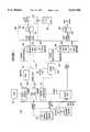
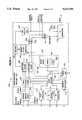
- FIG. 1is a block diagram of an example of a first Video Dial Tone Network utilizing a Level 1 Gateway which may be utilized with the present invention.
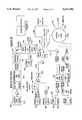
- FIG. 2is a block diagram of one example of an alternate network architecture utilizing a Level 1 Gateway in a manner adapted to the present invention.
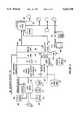
- FIG. 3illustrates a hybrid fiber coax network architecture utilizing the Level 1 Gateway in a manner adapted to the present invention.
- FIG. 4illustrates a digital entertainment terminal which may be utilized with the present invention.
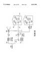
- FIG. 5illustrates the implementation of the invention according to one embodiment utilizing the type of network illustrated in FIG. 1.
- FIG. 6illustrates another embodiment of utilization of the invention in a network of the type illustrated in FIG. 1.
- FIG. 7shows a simplified block diagram of a translator or transponder which may be utilized in the invention.
- FIG. 1is a block diagram an exemplary broadband network for providing interactive services, such as video on demand, home shopping or purchasing, home banking, medical information, ticket ordering, gaming, etc.
- the customer premises equipmentCPE
- CPEcustomer premises equipment
- POTStelephone
- the connections to the central officeutilize Asymmetrical Digital Subscriber Line (ADSL) technology, typically over twisted wire pair, similar to that disclosed in the above cited Litteral et al. Patent.
- the ADSL connectionprovides a 1.5 mbits/s downstream video information channel, a two-way telephone connection and a two-way 16 kbits/s control channel.
- the illustrated Video Dial Tone network architecturemay use some form of fiber extension in the actual subscriber loops, to provide services to subscribers located more than 1.5 kilo-feet from a central office (see e.g. U.S. patent application No. 08/233,579, in the name of Bruce Kostreski, filed Apr. 26, 1994 and entitled "Extended Range Video On Demand System”).
- the drop to the subcriber's premisesis a wired ADSL loop.
- the network interface module in the DET 100connects to an ADSL multiplexer/demultiplexer 201 similar to the in-home ADSL unit in the above discussed Litteral et al. Patent.
- the connection between the network interface module of the DET 100 and the in-home ADSL unit 201may consist of an RJ48C line and connectors.
- Such a linkcomprises six wire pairs, two for the broadband data, two for upstream signaling and two for downstream signaling.
- the distribution on the premisewill differ in the region indicated by the broken lines 500, as is described in detail hereinafter.
- Each ADSL subscriber line 203connects to an ADSL bay 205 located in or associated with the subcriber's local central office.
- the ADSL bay 205includes an ADSL multiplexer/demultiplexer similar to the central office ADSL unit in the above discussed Litteral et al. Patent.
- the ADSL bay 205provides transport for voice signals on the subscriber loop to and from the associated voice switch 207.
- the ADSL bay 205also connects to an access concentrator 209 for providing two-way signaling connections through an X0.25 type packet switched data network 211.
- the ADSL bay 205also receives broadband digital signals for downstream transport over the ADSL line 203 to each subcriber's premises from a digital cross connect switch 213, labelled "Access DCS" in the drawing.
- One ADSL line 203 to the homecarries one channel of video programming and provides a single output channel.
- the output channelcan provide a video signal to a VCR (not shown) or to the TV set 100'.
- the various Access DCS switches throughout the networkare controlled by switch controller 212.
- the ADSL bay 205connects to the Access DCS 213 via an appropriate number of local DS1 connections 215.
- the ADSL baywill be located in a remote central office facility.
- Such a remote ADSL bayconnects to the Access DCS 213 via a SONET type optical fiber link 217 providing an appropriate number of multiplexed channels to service the number of subscribers connected to the particular ADSL bay.
- Video Information service Providersmay access the downstream broadband portion of the system at a hub location (not shown) within a given LATA.
- the hubwill not perform any switching.
- High capacity optical fiber linksare aggregated at the hub to provide each VIP with a number of connections (e.g. one or more OC-3 links) from their respective video server to each Access DCS within the LATA.
- the Access DCS 213provides both point-to-point connections and point-to-multipoint connections.
- Individualized interactive servicessuch as Video On Demand, home shopping/purchasing and banking, use point-to-point connections wherein the Access DCS connects one broadband input port from a VIP's server to one output port going to the subcriber's ADSL line.
- Narrowcast and broadcast servicesutilize point-to-multi-point connections of one input port to a plurality of output ports.
- the illustrated architecture of the Video Dial Tone networkutilizes two levels of gateways, both of which will communicate with subscribers' DET's via the X.25 data network 211 and the signaling channel on the ADSL subscriber loops 203.
- the Level 1 Gateway 221performs a variety of network connectivity related functions, including communications port management of transmissions of information between subscribers and servers, processing of billing information and session management. Normally, each subscriber accesses the Level 1 Gateway (e.g. to select and access a particular VIP's server) by operation of a remote control device which causes the subcriber's DET 100 to transmit data signals to the Level 1 Gateway via the 16 kbits/s control channel and the X.25 packet switched data network 211. The Level 1 Gateway transmits one or more selection menus to the subcriber's DET 100 as screens of text data carried by the same path back through the network.
- the Level 1 Gatewaytransmits one or more selection menus to the subcriber's DET 100 as screens of text data carried by the same path back through the network.
- text or graphics information from the Level 1 Gatewayis displayed as a page of data.
- the text or graphics datacould be overlaid on a video display received through the broadband network, e.g. over one of the broadcast channels carried through the more advanced networks discussed below.
- the userwould turn on the DET terminal 100, and in response to data signals from the Level 1 Gateway 221, the terminal would display an initial selection menu.
- the subscriberwould input a selection, and in response to an appropriate data signal from the DET 100, the Level 1 Gateway 221 would instruct the various network components to set up a virtual circuit to the level 2 gateway of a selected VIP for signaling purposes and a direct downstream path from the VIP's server through the digital cross-connect switch 213 for video transmission.
- the Level 1 Gateway 221accumulates usage statistics relating to the broadband communication links through the network and supplies those statistics to a billing system, e.g. to a carrier access billing system (CABS) 227 as shown in FIG. 1.
- CABScarrier access billing system
- the Level 1 Gateway 221also exchanges various network operational status information with the switch controller 212 and with a video provider service center (VPSC) 231.
- VPSCvideo provider service center
- a level 2 gatewayprovides a number of services for the Information Providers. These services include transmission of menus of available information to subscribers, searches of available information, targeted advertisement insertion, previews, trailers, etc.
- the level 2 gatewaywill download video or audio menus to each subcriber's DET for display, thereby allowing each subscriber to select desired information. Once a subscriber makes a selection, the level 2 gateway will signal the appropriate server to schedule transmission of the selected information through the established downstream video transmission path.
- the Level 1 Gatewayaccumulates connectivity charge information for purposes of billing each called VIP.
- the level 2 gatewayrecords transactions, e.g. movies viewed, by each subscriber for billing purposes.
- the level 2 gatewayalso interacts with the DET 100 and controls the associated servers to download executable program code for storage in the DET system memory.
- the switch controller 212monitors operations of the digital cross connect switches 213 and provides appropriate information to the Level 1 Gateway. For example, if the switch controller 212 indicates that a broadband communication link through one of the switches has failed for some reason, the Level 1 Gateway will terminate its accumulation of usage data for billing for the particular broadband session.
- the video provider service center (VPSC) 231performs a related monitoring function with regard to the ADSL loops.
- the ADSL bays 205monitor communications over the subscriber lines 203 by periodically enquiring as to the status of each on-premise ADSL unit 201.
- the ADSL bays 205in turn inform the video provider service center (VPSC) 231 of any detected failures via data connections to that center (only one such data connection is illustrated in FIG. 1).
- the service center (VPSC) 231is manned with operations support personnel.
- the center 231provides a display for review by one of the technicians.
- a VIPmay also call in and indicate that the VIP's system 252 has detected some form of failure.
- the techniciandecides whether in fact a failure has occurred. If so, the technician initiates an X.25 data call and transmission of a message from the video provider service center (VPSC) 231 to the Level 1 Gateway 221 identifying the failed link and instructing the Gateway 221 to tear down the particular broadband link.
- the Level 1 Gateway 221terminates its accumulation of usage time data for that link and instructs the switch controller 212 to tear down the link.
- personnel at the centercan initiate action to correct the fault. For example, if the switch controller 212 reports a fault in a particular switch 213, the personnel at the service center (VPSC) 231 can call a technician at the central office housing that switch and have that technician test the switch and correct any faults actually discovered. Similarly, if an ADSL bay 205 reports some fault on the twisted wire pair 203 or loss of communications with the on-premises ADSL unit 201, the personnel at the service center (VPSC) 231 can dispatch a repair technician to locate and correct the fault on the line or in the on-premises unit.
- the function of the video provider service center (VPSC) 231be fully automated to instruct the Level 1 Gateway 221 to stop billing data accumulation and tear down faulty broadband links without human intervention.
- the Video Dial Tone network of FIG. 1provides video on demand and other broadband interactive multimedia services offered by a plurality of service providers. For example, using the upstream data channel, the subscriber can send a request for a particular movie from his VIP of choice, and the VIP's server will retrieve and transmit that movie as an MPEG digital data stream on the 1.5 Mbits/s downstream channel to the digital audio/video processor in the subcriber's DET 100.
- MPEGmoving picture experts group
- MPEG 2is a second generation compression standard for packetized transport of one or more compressed video program signals in a single stream.
- a number of specific compression algorithmswill satisfy MPEG requirements.
- MPEGpermits encoding of audio/video program materials into digitized, compressed format at rates in the range of 1.5 to 6 Mbits/sec.
- the DET 100includes a CPU, comprising a 386 or 486 microprocessor and associated memory (RAM, ROM and EPROM) and an audio/video decoder, controlled by the CPU.
- the audio/video decoderdecompresses the digitized broadband information.
- the preferred embodiment of the audio/video decodercomprises an MPEG video decoder, an MPEG audio decoder, and an MPEG demultiplexer for selectively routing MPEG encoded video and audio packets carried on the digital broadband channel to the MPEG video decoder and the MPEG audio decoder, respectively.
- the DETalso includes a graphics display generator for generating displays of received text data, such as the initial turn-on selection menu, discussed in more detail below.
- the DETalso includes digital to analog converters and appropriate drivers to produce output signals compatible with a conventional television set from the decoded audio/video information and the graphics display.
- Each DETalso includes means to receive selection signals from a user and transmit appropriate data signals over a narrowband channel through the particular video network.
- the digital entertainment terminal (DET) 100is a programmable device to which different individual video information providers (VIP's) can download different applications software. At least one VIP, typically a vendor of the DET, also can download portions of the operating system.
- VIPtypically a vendor of the DET
- the DETwill permanently store only an operating system and a loader program, to control initial communications with a Level 1 Gateway or to facilitate initialization into a simplified CATV type mode of operation.
- FIG. 1The operation of the network of FIG. 1 is described in further detail in commonly assigned application Ser. No. 08/304,174 filed Sep. 12, 1994, entitled “Level 1 Gateway for Video Dial Tone Networks” (680-093), which is incorporated entirely herein by reference.
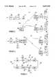
- FIG. 5there is shown one arrangement for providing wireless on-premise distribution of the 1.5 mbits/s downstream video information channel and two-way 16 kbits/s control channel using the ADSL architecture described above in connection with FIG. 1 according to a first embodiment of the invention. It will be understood that the invention is also applicable to other distribution architectures presently to be described. The same reference numerals have been used in FIG. 5 as are found in FIG. 1 where applicable.
- the CPE premiseincludes multiple television sets here indicated at 100' and 100" connected to multiple DET's 100 and 100a. These DETs are in turn connected to ADSL units 201 and 201'.
- the remote ADSL 205is shown beyond the CPE and is connected through a subscriber line to a filter 402 which separates the two-way voiceband signal to the POTS 404 and the multiplexed broadband 1.5 mbits/s television signal and two-way 16 kbits/s signaling channel delivered via connection 406. These signals on connection 406 are inputted to a suitable transponder 408.
- the transponder 408translates the frequency of these inputted signals to the radio frequency range and radiates the same through a suitable antenna 410.
- the radiated signalsare received by antennas 412 and 414 associated with transponders 416 and 418.
- the transponders 416 and 418translate the radio frequency signals back to the original 1.5 mbit/s and 16 kbits/s signals which are then fed as inputs to the ADSL units 201 and 201' for delivery to the DETs 100 and 100a and television sets 100' and 100" in the manner described in connection with FIG. 1.
- the transponderscomprise linear translators having a receiver or input pass band wide enough to include multiple channels. These signals are amplified, shifted to a new frequency range, and in the case of the transponder 408, then transmitted as radio frequency signals without modulation or alteration of the signal content.
- the transponders 416 and 418receive the radio frequency signals, translate the frequency to the original 1.5 mbits/s and 16 kbits/s and input the same to the ADSL units 201 and 201'.
- a typical such transponder or translatoris illustrated in FIG. 7.
- the transponderis in many respects similar to a transceiver in that it possesses a pair of signal handling channels for operating in converse fashions on signals in opposite directions.
- the input/output terminals 424 and 426are served by channel 420 to handle signals in the direction of the arrow 428 while channel 422 handles signals in the opposite direction indicated by the arrow 430.
- Channel 420may receive at input/output terminal 424 the 1.5 mbits/s and 16 kbits/s signals, amplify the same via amplifier 432, and deliver the amplified signals to a mixer 434, fed by the oscillator 436.
- the mixingraises the frequency to the radio frequency range and this signal is passed through a filter 438 and amplifier 440 to the input/output terminal 426.
- the terminal 426would terminate in the antenna 410.
- the transponders 416 and 418 receiving the radio signal from the antenna 410would handle the incoming signals in a converse fashion through the channel 422.
- the radio frequency signalswould be received by an antenna connected to the terminal 426.
- This signalwould pass through amplifier 442, mixer 444, controlled by oscillator 446, filter 448, and amplifier 450.
- the upstream 16 kbits/s control signal from the ADSLis raised to radio frequency and transmitted back to the transponder 408.
- the radio frequency signalis translated back to the 16 kbits/s form and delivered upstream to the remote ADSL 205 for the control purposes described in connection with FIG. 1.
- transponder circuitsmay be utilized in a manner well known in the art. See, Radio Handbook, 23d edition, William Orr, SAMS Division of MacMillan Computer Publishing, 1987; Satellite Communications, Robert M. Gagliardi, Lifetime Learning Publications, 1984; and Digital Satellite Communications, 2d edition, Tri T. Ha, McGraw-Hill Communications Series, McGraw-Hill Publishing Company, 1990.
- FIG. 6there is shown another embodiment of wireless CPE distribution using an ADSL system. Similar reference numbers are used where applicable.
- a single CPE ADSL unitis utilized connected to the subscriber line 203 and feeding the 1.5 mbits/s and 16 kbits/s signals to the transponder 408. These signals are translated to radio frequency and transmitted in turn to transponders 416 and 418. The transponders translate the radio frequency back to the original 1.5 mbits/s and 16 kbits/s signals and deliver the same to the DET's 100 and 100a.
- the return or upstream 16 kbits/s control signalsare translated to radio frequency in transponders 416 and 418, transmitted to transponder 408 and there returned to the 16 kbits/s form for input to the ADSL 201 and transmission upstream to the remote ADSL 205.
- the telephone (POTS or ISDN) circuitis separated from the incoming signal on the subscriber line at the filter 402 (or equivalent) device in the case of an ISDN installation.
- the POTS lineis broken out from the ADSL as described in connection with FIG. 1.
- FIG. 2depicts an example of one such advanced video dial tone network utilizing the Level 1 Gateway.
- the illustrated networkutilizes an advanced fiber to the curb system with ATM (Asynchronous Transport Mode) transport, and is similar to one of the networks disclosed in commonly assigned application Ser. No. 08/250,792, filed May. 27, 1994, entitled “Full Service Network” (attorney docket No. 680-080), the disclosure of which is incorporated herein entirely by reference.
- the network of FIG. 2uses essentially a switched star type architecture.
- the Full Service Network illustrated in FIG. 2provides broadcast video distribution, archival video services and interactive multi-media services as well as a suite of narrowband services including plain old telephone service.
- the broadcast video serviceswill initiate from a broadcast type server, such as ATM video source 1101 or aa digitally encoded off the air TV signal.
- the broadcast server source 1101includes an actual analog video source 1110. Although only one is shown, a typical broadcast service provider will have a plurality of such video sources in the same or separate server systems.
- the analog signal from the sourceis carried by any convenient means, such as an optical fiber, etc.
- Means(not shown) are provided as necessary to convert analog video transmission signals, e.g. NTSC broadcast signals, to baseband video and audio signals.
- the baseband signalsare applied to a real time encoder 1120.
- the real time encoder 1120digitizes the audio and video signals and performs data compression. As currently envisaged, the encoder will encode the program signal into an MPEG 2 format.
- the illustrated real time encoder 1120preferably is set up as a bank of encoders to process six or more sets of analog audio/video program signals in parallel.
- the bank of encoders 1110produces six 6 Mbits/sec MPEG 2 bit streams, which are combined together with appropriate overhead information into a single 45 Mbits/sec DS-3 type signal.
- the DS-3 signal from the encoder 1120is input to an interworking unit (IWU) 1130.
- the interworking unit 1130is the actual input point for the encoded broadcast video information into the Full Service Network of FIG. 2.
- the Full Service Networkuses asynchronous transfer mode (ATM) switching to transport all broadband or video information, including the broadcast video information.
- ATMis a packet oriented time division multiplexing technique.
- informationis organized into cells. Each cell includes a header, primarily for identifying cells relating to the same virtual connection, and an information field or "payload".
- a 53 octet ATM cellwould include a cell header consisting of 5 octets and a payload consisting of 48 octets of data.
- One MPEG 2 packetwould be mapped into payload data in four such ATM cells. Transfer is asynchronous in the sense that the recurrence of cells that contain information from any particular sender is not necessarily periodic.
- Each device using the ATM networksubmits a cell for transfer when they have a cell to send, not when they have an assigned or available transmission time slot.
- ATMallows any arbitrary information transfer rate up to the maximum supported by the ATM network, simply by transmitting cells more often as more bandwidth is needed.
- all video materialswill be transferred at a constant, standardized bit rate.
- Preferred later generations of the networkwill utilize the ATM capabilities of the network to permit transmission of video information over channels of different bit rates, e.g. 1.5 Mbits/sec, 3 Mbits/sec, 6 Mbits/sec, etc. It will also be possible to vary the bit rate during communication on an as needed basis.
- the interworking unit 1130grooms the continuous MPEG 2 bit streams of the broadcast services for ATM cell stream transmission over optical fiber transport links. For example, the interworking unit will divide the bit stream into appropriate length payloads and combine the payload data with appropriate cell headers, necessary for ATM transport. In an initial implementation, downstream links would carry an OC-12 bit rate, but higher rate transports such as OC-48 will be used in later implementations. Assuming use of OC-12, one such transport link will normally carry the equivalent of 112 DS-3's. However, conversion into ATM cell format with associated headers imposes added overhead requirements on the data transmissions. In the presently preferred embodiment, one interworking unit 1130 therefore processes up to ten DS-3 signals to produce an ATM bit stream at the OC-12 rate.
- a transport interface 1140converts the electrical signal from the interworking unit 1130 into an optical signal and transmits the optical signal through fiber 1150 to an adaptive digital multiplexer (ADM) identified in the drawing as a video bridging and insertion device 1160.
- ADMadaptive digital multiplexer
- the ADM 1160performs three functions, passive bridging, active bridging and insertion of signals from other broadcast service providers (if any). The three functions may actually be separate, but in the preferred embodiment, all three would be performed by elements collocated within the one network component ADM 1160.
- the real time encoders 1120each output a single DS-3 signal comprising up to 6 MPEG 2 bit streams.
- the interworking unit 1130processes up to ten DS-3 signals to produce an ATM bit stream at the OC-12 rate. Consequently, one broadcast video source 1101 may produce as many as 60 channels of CATV type broadcast programming for transport over one OC-12 type SONET optical fiber 1150. Many,providers, however, may not choose to broadcast so many channels. For example, the provider operating broadcast video source 1101 may offer only 42 channels. Such an ATM channel transmission on the optical fiber 1150 will not utilize the entire OC-12 channel capacity of that fiber. In the specific example, the 42 channels together require the equivalent of 7 of the available 10 DS-3's.
- the illustrated architecturepermits a second broadcast service provider to utilize the transport capacity not used by the first provider.
- the second broadcast service providerwould offer additional channels from a separate second source 1101'.
- the source 1101'is essentially identical in structure and operation to the source 1101, but the source 1101' will offer up to the number of channels necessary to fill the OC-12 transport capacity. In the example, if the source 1101 transmits 42 channels (7 DS-3's) via the fiber 1150, the second source 1101' could transmit up to 18 additional channels (3 DS-3's).
- the function of the insertion device in the ADM 1160is to combine the signals from the two sources into a single OC-12 rate signal (10 DS-3's in ATM cell format) for further transmission through the optical network.
- the two bridging functionsfacilitate dissemination of the broadcast material throughout the entire Full Service Network.
- the passive bridging elementsare optical splitters for splitting one OC-12 optical signal from the insertion device into a number of duplicates thereof, e.g. 1:2, 1:4, 1:8, etc.
- the active bridging elementsconvert an optical signal to an electrical signal, regenerate the electrical signal and convert the regenerated signal back to an optical signal for application to multiple output ports.
- the optical OC-12 output signals from the bridging componentsare transmitted over a large number of optical fibers 1170 to host digital terminals throughout the network service area.
- the host data terminal (HDT) 1180is shown as a representative example.
- the digital entertainment terminal (DET) in the subcriber's homeprovides a signal identifying the selected channel to the HDT 1180.
- the signaling between the digital entertainment terminal (DET) and the HDT 1180will be discussed in more detail below.
- the ATM cell stream from an optical fiber 1170is applied to a bus.
- One HDTwill communicate with a large number of optical network unit (ONU's) 1210, two of which are shown.
- the HDTwill communicate with each ONU 1210 via a pair of optical fibers 1190.
- each home or living unitwill have as many as four DET's.
- Each ONU 1210 and the downstream fiber of the pair 1190 to the ONU 1210will provide downstream video services to a number of homes, e.g. 8 to 24.
- the transmissions on the downstream fibers between the HDT and the ONU's 1210are synchronous, although the video information remains in ATM cell format.
- Each DET served by an ONU 1210is assigned a specified time slot on the downstream fiber of a pair 1190.
- the HDT 1180includes a component which is essentially a non-blocking type ATM switch.
- the HDT 1180accesses the appropriate bus and identifies each ATM cell on that bus for which the header information indicates that the cell represents information for the selected broadcast channel.
- the identified ATM cellsare bridged by the ATM switch from the bus to a line card providing transmissions over the optical fiber 1190 to the particular ONU 1210 which services the requesting subcriber's premises.
- elements on the line card communicating with the particular ONUwill buffer the cell as necessary and place the cell in the time slot for that DET on the downstream fiber of optical fiber pair 1190.
- the cells selected for a particular DETtogether with cells going to other DET's served by the same ONU multiplexed into their respective time slots, are applied to an electrical to optical converter and transmitted over the downstream fiber to the ONU 1210 serving the particular subcriber's premises.
- the basic purpose of the ONUis to desegregate the HDT side links into individual customer links and provide optical to electrical conversion for electrical delivery to the individual subscribers' premises.
- the drop cable to each subcriber's premisescomprises a coaxial cable for carrying the video and/or two-way digital data signals and a twisted wire pair for carrying telephone signaling.
- ADSL communications over twisted wire paircould be used between the ONU and the subscribers premises.
- the ONUincludes means to convert optical signals received over the downstream fiber to electrical signals and transmit signals from each DET's assigned time slot down over the coaxial cable to the subcriber's premises.
- the ONUalso provides two-way conversion between optical and electrical signals for voice telephone service over the twisted wire pairs and for the signaling channels to/from the DET's.
- a power source 1211supplies -130 V dc and battery reserve power for telephone service to the ONU's 1210.
- the power source 1211may connect to the ONU's via twisted pairs, but in the preferred embodiment, the power is carried over a coax distribution cable.
- the digital entertainment terminal (DET) 1217is a programmable device to which different applications programs and/or portions of the operating system will be downloaded from a gateway device in order to permit the DET to interact with different information service providers and thereby offer the user totally different types of services.
- the DETmay be similar to that used in the network of FIG. 1, with the exception that the network interface module within the DET 1217 provides the various broadband and signaling connections to a coaxial cable, instead of to an interface to an ADSL twisted wire pair type line, and the communication software within the DET is adapted to process ATM transported information.
- the DET 1217includes means (not shown) to demodulate received data and convert ATM cell stream data into bit stream data for further processing.
- the DET 1217also includes a digital signal processor to decompress received video signals as well as a graphics display generator for generating displays of text data, such as the initial turn-on selection menu.
- the DETwill also include a digital to analog converter and appropriate drivers to produce output signals compatible with a conventional television set.
- Each DET 1217also includes the means to receive selection signals from a user and transmit appropriate data signals over a narrowband channel on the coaxial drop cable to the ONU 1210.
- the ONUmultiplexes the user input data signals from the DET's it services together and transmits those signals to the HDT over an upstream fiber of the optical fiber pair 1190.
- the HDTtransmits the upstream control signals to control elements referred to as gateways.
- the HDT'scommunicate with the gateways through an X.25 type data network. Future implementations will use ATM communications for the signaling.
- the Level 1 Gateway 1230provides primary control of all routing and access functions of the network and accumulates various usage statistics, in a manner substantially similar to that of the Level 1 Gateway 221 in the network of FIG. 1.
- the control functionsinclude controlling access to broadcast programs by individual subscribers. Control of access to on demand programming and interactive multimedia services through a PVC controller 1420 and an ATM switch 1410 will be discussed in more detail below.
- the Level 1 Gatewayalso will transmit narrowband information to the DET 1217 instructing it to initiate display of various selection menus of available video information service providers.
- the Level 1 Gatewayconnects to a service administration module (SAM) which maintains a data base of video information service providers and customer profile data for the broadcast, archival and interactive video services available through the network. This data may include customized menus, pre-subscription information, identification of impulse pay per view events and premium channels, etc. Under different circumstances, the video information providers and/or the individual customers can access this data for provisioning.
- SAMservice administration module
- the Level 1 Gatewayalso connects to an operations support module (OSM).
- OSMoperations support module
- the operations support moduleprovides an interface to standard operating support systems used for additional network provisioning functions.
- the DET 1217transmits data upstream through the various network elements to the Level 1 Gateway identifying the selected channel.
- the Level 1 Gateway 1230accesses stored data regarding the broadcast services to which the customer currently subscribes. If the customer subscribes to the requested service, the Level L Gateway 1230 transmits an instruction to the HDT 1180 to route the cells for that channel to the subcriber's DET 1217 in the manner discussed above. If the customer is not currently a subscriber to that service, the Level 1 Gateway 1230 transmits a data message back to the DET 1217 instructing it to provide an appropriate television display, e.g. informing the customer of a service denial and/or asking the subscriber for appropriate inputs to initiate a new subscription.
- the above selection procedure through the Level 1 Gatewayprovides the Gateway 1230 with information as to each selection a subscriber makes and when the selection is made.
- the Level 1 Gatewayalso receives information as to when a DET session ends, e.g. upon turn-off of the DET or upon request for a session with a different provider.
- the Level 1 Gatewayhas all information necessary to accumulate a variety of statistics as to viewer usage both for billing purposes and for audience accounting purposes.
- certain relevant control datacould be downloaded to the HDT, either from the Gateway 1230 or from the service administration module (SAM).
- SAMservice administration module
- the broadcast VIP'swould provide provisioning data to the SAM, and the SAM periodically downloads that data to the appropriate HDT's, either directly or through the Level 1 Gateway 1230.
- the provisioning data downloaded to the HDT's 1180would include channel mapping information and subscriber authorization control information.
- the channel mapping informationspecifies what programs are carried on each ATM virtual circuit, within each DS-3, on each respective optical fiber 1170.
- the HDT 1180accesses the channel mapping information in response to each program selection by a subscriber to route the ATM cell stream to the requesting DET.
- the authorization control datawould indicate which program each subscriber is authorized to access, e.g. because that party has subscribed to the particular program service and is not delinquent in bill payments. When a subscriber requests a program, the HDT 1180 would check this data to determine whether or not to supply the program to the subcriber's DET 1217.
- the HDT 1180As the HDT 1180 routes selected channels to the DET's 1217, the HDT would accumulate usage data and/or pay per view event purchase data for the subscribers serviced thereby. The HDT 1180 would periodically upload such usage data to the Level 1 Gateway 1230 and/or to the SAM for subsequent transmission to appropriate billing systems of the network service provider or the VIP's, respectively.
- the network of FIG. 2offers subscribers access to other wideband services, such as video on demand and interactive multimedia services. Access to these additional broadband services is through an ATM switch 1410. As discussed in more detail below, the access through this switch is controlled by the Level 1 Gateway 1230 in a manner quite similar to the routing to a VIP in the network of FIG. 1.
- Each of the non-broadcast service providers 1400will have a level 2 Gateway 1401 and some form of file server 1403 or other source of information.
- the video information provider's (VIP's) systemmay provide ATM cell stream outputs for transmission through the network.
- the network operatorwould supply an interworking unit similar to the unit 1130 discussed above to convert the provider's bit stream data into an ATM cell stream format compatible with the Full Service Network.
- the ATM switchtransmits selected ATM cells via optical fibers 1415 to the HDT's 1180.
- a PVC controller 1420stores data tables defining all possible virtual circuits through the ATM switch and the HDT's to each terminal of a customer subscribing to a particular provider's services. These data tables define the header information and the particular fiber output port used to route cells to the correct HDT and the time slot information on the downstream fiber to the appropriate ONU serving each DET. The data tables thus define "permanent virtual circuits" (PVC's) between the providers and the DET's.
- the subcriber's DET 1217When a subscriber initiates a session with a broadband interactive service provider, for example VIP 1400, the subcriber's DET 1217 provides an appropriate "off-hook" signal to the HDT 1180.
- the HDT 1180sends the message through the X0.25 packet switched network to the Level 1 Gateway 1230.
- signalingmay also be achieved using ATM calls through HDT and ATM video switch to the level 1 Gateway 1230.
- the Level 1 Gateway 1230receives the addressed message from the HDT, that Gateway uses the X.121 or other protocols address of the caller included in the message to check its internal database to determine if the caller is a valid network customer. If the caller is not a valid customer, the system tears downs the session. If the caller is a valid customer, the Level 1 Gateway 1230 transmits an X.25 or ATM call accept message back to the terminal and waits for the first application level message.
- the DET 1217sends an initiation message that says "hello".
- This "hello" messageincludes basic information such as a customer premises equipment (CPE) identifier and a CPE type designation.
- the Level 1 Gateway 1230sends a menu and a banner through the downstream signaling channel, as in the earlier network embodiment.
- the menuis a screen of text listing VIP's available to this customer or the VIP's that the customer as previously selected for purposes of her customized menu presentation.
- the subscriberreviews the menu on their television set, and operates the arrow keys on the DET remote control to move a cursor across the menu to an appropriate point on the screen, after which the user presses an ⁇ ENTER> key on the keypad or remote control.
- the DET 1217transmits an appropriate data signal upstream through the network to the Level 1 Gateway 1230.
- the Level 1 Gatewaymay execute a PIN number access routine, as in the earlier embodiment, if the subscriber has previously requested such access control for selected ones of the VIP's. For simplicity here, it is assumed that the currently selected VIP is not subject to such a PIN number requirement.
- the Level 1 Gatewayis merely expecting to receive the VIP selection input from the DET within a predetermined period following the menu transmission. If the Level 1 Gateway receives the selection input message from the DET within the predetermined period, the Gateway 1230 translates that message into the 4 digit code for the selected VIP's Level 2 Gateway.
- the Level 1 Gatewaysends a message to the DET saying please wait while we connect to the VIP.
- the Level 1 Gatewaythen goes over the X.25 or ATM network to communicate with the selected VIP's Level 2 Gateway.
- the Level 1 Gateway 1230contacts the level 2 Gateway 1401 and indicates that it has a customer calling.
- the Level 1 Gateway 1230identifies the customer to the level 2 Gateway 1401 by sending the standard billing telephone number for the calling customer to the Level 2 Gateway.
- the CPE identification information and the CPE-type information that was sent in the initial origination messageis also sent to the Level 2 Gateway (VIP) at this time.
- VIPLevel 2 Gateway
- the VIP's Level 2 Gatewaymay accept or reject the call after receiving the initial request indicating a customer is available, as in the network of FIG. 1. If the Level 2 Gateway 1402 sends a message back to the Level 1 Gateway 1230 indicating a rejection of the call, the Level 1 Gateway transmits a message to the DET 1217 instructing that terminal to display some form of call rejection notice on the associated TV.
- the Level 2 Gateway 1401accepts the call, provides a server output port and gives a port identification for the port on the server 1403 to the Level 1 Gateway 1230.
- the Level 1 Gatewaytransmits the X.121 address of the calling customer's DET 1217 to the Level 2 Gateway 1401.
- the Level 2 Gatewayuses that address to initiate a new signaling communication through the X.25 network 1220 with the subcriber's set-top terminal DET 1217.
- the Level 1 Gatewayidentifies the broadband communication link number for the channel going out from the HDT to the requesting customer's DET 1217.
- the Gateway 1230sends a message to the PVC controller 1420 to establish a virtual circuit between the selected provider 1400 and the subcriber's DET 1217.
- the PVC controlleraccesses its data tables to identify an available permanent virtual circuit between the provider 1400 and the DET 1217 for which all necessary elements are currently available.
- the PVC controller 1420provides appropriate instructions to the ATM switch 1410 and informs the Level 1 Gateway 1230 of the virtual circuit identifier.
- the Level 1 Gateway 230informs the HDT 1180 of that virtual circuit identifier and instructs the HDT 1180 to "lock-up" that circuit as a currently active virtual circuit providing broadband communications from the server 1403 of the provider 1400 to the subcriber's DET 1217.
- the PVC controller 1420transmits back an appropriate indication thereof to the Level 1 Gateway 1230. Then the Level 1 Gateway tears down its own X.25 signaling connection with the subcriber's set-top terminal. At the same time, the Level 1 Gateway 1230 informs the Level 2 Gateway 1401 that it has set up a good broadband link, and the Level 1 Gateway initiates a billing record for the call. Alternatively, if the PVC controller 1420 informs the Level 1 Gateway 1230 that it could not establish the broadband connection, the Level 1 Gateway passes that information on to the Level 2 Gateway 1401 and provides an appropriate message for display by the DET 1217 informing the customer.
- the DETcan transmit control signaling upstream through the ONU 1210 the HDT 1180 and the X.25 data network to the Level 2 Gateway 1401.
- the Level 2 Gatewaycan also send signaling information, such as control data and text/graphics, downstream through the same path to the DET 1217.
- the server 1403will provide ATM cells with an appropriate header.
- the ATM switch 1410will route the cells using the header and transmit those cells over fiber 1415 to the HDT serving the requesting subscriber.
- the HDT 1180will recognize the header as currently assigned to the particular DET 1217 and will forward those cells through the downstream fiber of pair 1190 and the ONU 1210 to that DET, in essentially the same manner as for broadcast programming.
- the Level 2 Gatewayinstructs the Level 1 Gateway 1230 to tear down the broadband connection.
- the instructionincludes the customer's billing telephone number and the server port identification for the VIP port used for the broadband communication.
- the Level 1 Gateway 1230stops the billing timing for that broadband session and transmits and instruction through the PVC controller 1420 to tear down the broadband connection between the server port and the customer's broadband port.
- the Level 1 Gatewaycreates a log record of the interactive broadband call for purposes of billing the VIP 1400 for the broadband connect time.
- the Full Service Network illustrated in FIG. 2will also provide narrowband transport for voice and narrowband data services.
- a digital switch 1310 or an analog switch 1330will provide standard type plain old telephone service (POTS) for customers of the Full Service Network.
- POTSplain old telephone service
- the digital POTS switchprovides a DS-1 type digital input/output port through interfaces conforming to either TR008 or TR303.
- the outputmay go to a digital cross-connect switch (DCS) 1320 for routing to the various HDT's or directly to a multiplexer (MUX) 1325 serving a particular HDT.
- the MUX 1325may also receive telephone signals in DS-1 format from the analog switch through a central office terminal 1333.
- the central office terminal 1333converts analog signals to digital and digital signals to analog as necessary to allow communication between the analog switch 1330 and the rest of the network.
- the MUX 1325serves to multiplex a number of DS-1 signals for transmission over one fiber of an optical fiber pair 1335 to the HDT 1180 and to demultiplex signals received over the other fiber of the pair 1335.
- the fiber pairs between the HDT 1180 and the ONU's 1210will also have a number of DS-1 channels to carry telephone and narrowband data signals to and from the subcriber's premises.
- the subscribers' drops 1215include both a coaxial cable and one or more twisted wire pairs.
- the ONUwill provide telephone signals and appropriate power to the subscribers' premises over the twisted wire pairs connected to subscribers' telephone sets 1219.
- the ONU'swill also provide two-way narrowband data communication to the DET's in narrowband channels over coaxial cable.
- FIG. 3depicts an alternate implementation of a further video network utilizing a Level 1 Gateway in accordance with the present invention.
- the network of FIG. 3is a hybrid fiber-coax system which provides RF transport of both analog and digital broadband services.
- the illustrated networkprovides broadcast video distribution, archival video services and interactive multi-media services as well as plain old telephone service.
- a telcodeploys a number of Loop Transport Interfaces 300, only one of which appears in the drawing (FIG. 3).
- each Loop Transport Interface 300will be located in a telco central office.
- several different central officeswould each have a Loop Transport Interface similar in structure to the Interface 300 depicted in FIG. 3.
- each Loop Transport Interfacewill serve as the headend of an otherwise conventional optical fiber trunk and coaxial cable type CATV distribution network.
- a laser type optical transmitter 303transmits downstream signals through fibers 305 to optical to electrical nodes referred to as "optical network units" or ONU's.
- the laseroperates in a linear mode in the range of 5-750 MHz.
- the transmitterhas an optical splitter and can transmit to several ONU nodes 309. Each ONU 309 performs optical to electrical conversion on the downstream signals and supplies downstream RF electrical signals to a coaxial cable distribution system 311.
- the optical transmitterreceives and transmits signals from an RF (radio frequency) combiner 315.
- the combiner 315combines and levelizes RF signals from several sources to produce the appropriate signal spectrum for driving the optical transmitter 303.
- One set of signals supplied to the RF combiner 315will be group of AM--VSB (amplitude modulated vestigial sideband) analog television signals from one or more appropriate sources not separately shown.
- AM--VSBamplitude modulated vestigial sideband
- Such signalsare essentially "in-the-clear" CATV type broadcast signals capable of reception by any subcriber's cable ready television set.
- the analog television signalsare broadcast from the optical transmitter 303 through the tree and branch optical and coax distribution network to provide "basic" CATV type service to all subscribers on the network.
- the Network operating companyoffers a standard CATV type analog frequency converter, or the subscriber could choose to purchase a converter on the open market.
- the network interface module in the DET 100awill also include a tuner that permits subscribers to the digital services to receive the analog broadcast channels through the same equipment used for the digital services.
- the Network depicted in FIG. 3also provides transport for digitized and compressed audio/video programming, both for certain broadcast services and for interactive services, such as video on demand. Such programming will be encoded and compressed in MPEG-2 or other format. As discussed in more detail below, the present invention permits specific use of MPEG encoded materials to offer a variety of interactive services without continuously utilizing a full MPEG encoded broadband channel to transport information to the subcriber's DET 100'.
- the MPEG encoded videois transported to each Loop Transport Interface using asynchronous transfer mode (ATM) transport and switching.
- ATM informationis organized into cells each comprising a header, primarily for identifying cells relating to the same virtual connection, and an information field or "payload".
- the ATM cell header informationincludes a virtual circuit identifier/virtual path identifier (VCI/VPI) to identify the particular communication each cell relates to.
- VCI/VPIvirtual circuit identifier/virtual path identifier
- the VCI/VPIwill identify a particular program channel.
- the VCI/VPI in each header of the ATM cellswould effectively identify a specific end point of the virtual communication link.
- digital broadcast service signals 318 in MPEG encoded form and arranged in ATM cell packetsare applied to an ATM packet handler 319 in the Loop Transport Interface 300.
- These broadcast service signalsoriginate in one or more broadcast VIP's ATM servers which are essentially the same structure as the servers/sources 1101, 1101 shown in FIG. 2.
- the ATM broadcast serviceswill carry premium service type programming.
- the ATM broadcast signalsmay originate from any appropriate source (not shown).
- the ATM broadcast cell stream signalsoriginate from a server 403', as discussed in more detail below.
- Fully interactive broadband digital signals, in MPEG--ATM formatare also applied to the ATM packet handler from an ATM switch 401.
- the ATM packet handler 319terminates all ATM cell transport through the Network. This handler receives the ATM cell streams and converts the cell payload information into MPEG 2 bit streams.
- the RF combiner 315which prepares signals for downstream transmission by the optical transmitter 303 receives a variety of other analog RF signals from a group of RF digital modulators.
- the RF analog outputs from the modulatorscarry digital broadband information.
- the content for the digital RF modulatorscomes from the ATM packet handler 319.
- a network controller 323 and an associated network data processor (NDP) 325use the VCI/VPI header from the ATM cells to control the ATM packet handler 319 to route the MPEG bit streams to the appropriate ones of the digital RF modulators 317.
- U.S. Pat. No. 5,231,494 to Wachobteaches quadrature phase shift keyed (QPSK) modulation of a plurality of video, audio and data signals into a single data stream within a standard six MHz channel allocation for transmission over a CATV type distribution network.
- QPSKquadrature phase shift keyed
- the currently preferred implementationuses 64 QAM (quadrature amplitude modulation) or 16 VSB (vestigial sideband) modulation techniques in the RF modulators 317 in the Loop Transport Interface 300.
- 64 QAMquadrature amplitude modulation
- 16 VSBvestigial sideband modulation techniques
- 4 channels of 6 Mbits/s MPEG encoded digital video informationcan be modulated into one 6 MHz bandwidth analog channel.
- 16 VSByields 6 channels of 6 Mbits/s MPEG encoded digital video information modulated into one 6 MHz bandwidth analog channel.
- Each RF modulatorproduces a 6 MHz bandwidth output at a different carrier frequency.
- the 6 MHz bandwidth RF signals from the modulators 317are supplied to the optical transmitter 303 for downstream transmission together in a combined spectrum with the AM--VSB analog television signals 316.
- the downstream transport of the digital programmingis an RF transmission exactly the same as for the analog basic service channels, but each of the channels from the RF modulators 317 contains 4 or 6 digitized and compressed video program channels, referred to hereinafter as "slots".
- the 6 Mhz digital program channelswill be carried through the fiber and coaxial system in standard CATV channels not used by the analog basic service programming.
- the ONU 309is essentially transparent to both the analog basic service channels and the channels carrying the digital programming and supplies all of the signals as a combined broadcast over the coaxial cable network 311.
- the optical fiber 305 from the transmitter, the ONU's 309 and the coaxial distribution systems 311 thereforprovide a broadcast network transporting all downstream programming to all subscriber premises serviced thereby.
- a network interface module (NIM) 2101couples the set-top device or digital entertainment terminal (DET) 100a to a drop cable of the coaxial distribution network 311.
- the NIMincludes an analog frequency tuner controlled by the microprocessor 2110 (FIG. 4) to selectively receive the RF channel signals, including those channels carrying digital information.
- the NIMalso includes a QPSK, QAM or VSB demodulator to demodulate a selected one of the digitized program signals carried in one of the digital slots within a received 6 MHz channel and will perform a forward error correction function on the demodulated data.
- the digital audio/video signal processor 125 within the DETdecompresses received video signals, generates graphics display information and performs digital to analog conversion to produce output signals compatible with a conventional television set 100', exactly as in the earlier embodiments.
- the analog tuner in the NIMwill tune in all channel frequencies carried by the network, including those used for the analog broadcast services.
- the DET 100aincludes a bypass switch or the like and an analog demodulator to selectively supply analog signals from the basic service channels directly to the audio/video output terminals or to the modulator, to provide signals to drive a standard television receiver.
- the DET 100atherefore can be used as a frequency converter for reception of the analog signals.
- each DET 100aincludes a remote control and/or keypad to receive various selection signals from a user. At least in response to certain user inputs, such as selection of a pay per view event, the DET will relay data signals upstream over a signaling channel on the coaxial cable to the ONU 309. The actual transmission of any such data signals upstream from the DET 100a occurs in response to a polling of the DET by the ONU 309. The ONU 309 combines upstream data signals from the DET's serviced thereby and transmits those signals upstream over another optical fiber 307 to an optical receiver 308 in the Loop Transport Interface 300. Each DET 100a may transmit data on a different carrier frequency, in which case the network controller knows which DET sent particular data based on the received frequency channel. Alternatively, for interactive services, the DET may transmit a unique identification code with the upstream message.
- Certain digital program signals carried on the networkmay be encrypted using encryption technology and key codes. Details of specific encryption algorithms, the key codes and the precise techniques for downloading the key codes to the DET's are well known to those skilled in the art and familiar with the relevant patents and literature.
- an ACC 4000D 331serves as a video administration module (VAM). Obviously other equivalent products may be substituted.
- the ACC 4000D or VAMperforms set top management and specific program access control functions.
- service profiles for each customer on the network and their DET'sare set up and stored within the Level 1 Gateway 411.
- the Level 1 Gateway 411may also provide an interface to appropriate billing systems (not shown) for some broadcast services, such as pay per view.
- a subscriberwhen a subscriber first signs up, a portfolio of channels subscribed to by that customer is established in the subcriber's profile data within the VAM 331. Based on this profile data, the VAM will download a service map into the subcriber's DET 100a.
- the downstream transmission portion of the networkprovides an out-of-band downstream signaling channel to the DET's, for example for the downloading of the service map information from the VAM 331 to each DET 100a.
- This downstream signaling channelalso carries signals for controlling software downloading and/or selection of certain channels or frames for decoding in interactive services.
- each DET 100aincludes means for receiving and decoding each such digital broadcast service channel, as discussed above with regard to FIG. 1.
- the microprocessor in the DET 100acontrols access to any of these channels based on the downloaded map information stored in the system memory. For example, if one subscriber requests HBO, and that subscriber has paid to subscribe to HBO, the subcriber's DET 100a will contain map information instructing it to tune the RF channel and select and decode the digital program slot carrying HBO for display on the subcriber's television set 100'. However, if a requesting subscriber has not paid for HBO, the downloaded service map will not provide the requisite data for tuning and decoding of that channel.
- the illustrated Networkalso offers pay per view services through the ATM broadcast program channels 318.
- a userselects a pay per view event by operating the DET 100a.
- the DET 100atransmits a purchase message upstream through the Loop Transport Interface 300 to the Level 1 Gateway 411. If the authorization data in the subcriber's profile in the Level 1 Gateway indicates that the DET identification is valid and the subscriber is authorized to purchase such events, the Level 1 Gateway instructs the video manager 417 to authorize reception (and provide a decryption key if needed).
- the DET 100adecodes the pay per view event in essentially the same manner as for other premium services carried on the ATM broadcast channels 318, as outlined above. If the decryption key is needed, the Level 1 Gateway 411 actually instructs the video manager 417 to instruct the VAM 331 to transmit the key to subcriber's DET 100a.
- the implementation of the network illustrated in FIG. 3also provides telephone service. Between the optical network unit and the subscriber premises, the 700-750 MHz portion of the spectrum on the coaxial cable will carry the telephone signals. This allocated spectrum provides transport for 24 DS0 telephone channels. Each subscriber premises will have telephone interface referred to as a Cable Network Unit (CNU) 340 coupled to the coaxial cable which serves to couple two-way signals between a twisted wire pair into the home and the telephone frequency channels on the coaxial cable 311.
- CNUCable Network Unit
- Carrier frequencies used for telephone servicesmay be individually assigned to particular subcriber's CNU's.
- the telephone signal spectrumis carried on the same two fibers that carry the video and the upstream signaling between the Loop Transport Interface and the ONU.
- Upstream telephone signalsare applied from the optical receiver 308 to a host digital terminal (HDT) 343 which provides an interface to a standard digital telephone switch 345. Downstream telephone signals from that switch pass through the HDT 343 to the RF combiner 315 for transmission in the 700-750 MHz frequency range over the fiber to the ONU 309 and the coaxial cable distribution system 311.
- HDThost digital terminal
- the Loop Transport Interface 300would dynamically allocate the DS0 channels on the coaxial cable system 311 on a time-sharing basis, in essentially the same manner as in mobile radio systems. Two additional fibers and a second optical transmitter and receiver pair would carry the two-way telephone signals to and from the ONU 309. Because of the use of the separate optical links for telephone service in this alternate implementation the HDT and telephone switch need not be closely associated or collocated with any particular one of the Loop Transport Interfaces.
- the implementation of the network illustrated in FIG. 4offers access to video information providers (VIP's) for interactive broadband services, such as video on demand.
- VIPvideo information providers
- each VIPhas a Level 2 Gateway and some form of broadband information file server 403.
- the ATM switch 401provides communications links between the Loop Transport Interfaces 300 and the Level 2 Gateways and file servers 403.
- Customer access to the VIP'sis controlled through one or possibly more programmed computer or processor elements performing the processing functions of the Level 1 Gateway 411.
- a permanent virtual circuit (PVC) controller 415 and a video manager 417respond to signals from the Level 1 Gateway to control the point to point routing through the Network.
- PVCpermanent virtual circuit
- the PVC controller 415stores data tables defining all possible virtual circuits through the ATM switch 401 and the Loop Transport Interface 300 serving each DET terminal of a customer subscribing to each particular provider's services. These data tables define the header information and the switch port to the packet handlers needed to route cells to the correct Loop Transport Interface.
- the video manager 417stores similar data tables identifying the transmission fiber ports, RF channels and multiplexed digital channel slots which may be used to transport each data stream processed by the ATM packet handler 319 through the fiber 305 to the appropriate ONU 309 serving each DET.
- the data tables in the PVC controller 415 and the video manager 417thus define "permanent virtual circuits" between the VIP's equipment 403 and the DET's 100a.
- the subscriberoperates the DET 100a to interact with the Level 1 Gateway 411 and select a VIP in a manner similar to the operation in the network of FIG. 1.
- the PVC controller 415responds to instructions from the Level 1 Gateway by activating the ATM switch 401 to establish a downstream virtual circuit path between a port of the VIP's server and the ATM packet handler within the Loop Transport Interface 300 servicing a subscriber requesting a call connection to the particular VIP.
- the video manager 411assigns a particular one of the digitized video channel slots in a digital program type RF channel to carry the particular point to point communication.
- the video managercontrols the ATM packet handler 319 to route MPEG data recovered from the ATM cells for the particular point to point communication to the port for one of the RF modulators 317 so that the modulator will include the MPEG data in the assigned digital channel slot within a particular 6 MHz RF channel.
- the video manager 417also transmits a signal downstream through the signaling channel to the subcriber's DET 100a instructing the DET to tune to the particular RF channel and decode MPEG data from the specifically assigned digital channel within that RF channel.
- Similar dynamic assignments of RF channels on a CATV system to individual terminals for interactive servicesare disclosed in U.S. Pat. No. 5,220,420 to Hoarty et al. and U.S. Pat. No. 5,136,411 to Paik et al., the disclosures of which are incorporated herein in the entirety by reference.
- Level 1 Gateway 411would instruct the PVC controller 415 to control the ATM switch 401 to establish an upstream virtual circuit for control signals sent from the DET 100a up through the fiber-coax network and receiver 308 to the VIP's level 2, gateway.
- the combination of upstream and downstream, point to point channelsare used for downloading of operating system and applications software and for interactive service communications in essentially the same manner as in the Video Dial Tone Network of FIG. 1.
- the Level 1 Gateway 411receives status and failure notifications as part of its ongoing operations. These functions of the Gateway 411 are quite similar to those of the Gateway 212 in the network of FIG. 1 except that the Gateway 411 receives event notifications from more elements of the network. Also, in the presently preferred embodiment of the network of FIG. 3, the function of monitoring communications between the loop transport interface 300 and individual subscribers' DET's 100a is an automatic function of the video manager 417. In such an embodiment, there is no longer a need for the video provider service center (VPSC).
- VPSCvideo provider service center
- the video managermonitors 417 operations of the loop transport interface 300. As part of its monitoring function, the video manager 417 also determines the status of communications to each DET 100a. As such, the video manager automatically knows the status of all components between the input ports to the loop transport interface and the output ports of the DET's 100a.
- the video manager 417could periodically transmit a status interrogation signal to each DET 100a, through the out-of-band signaling channel. If currently operable, the DET would transmit a status message back upstream through the signaling channel informing the manager 417 of the DET's status, e.g. operable but idle or operable and actively in-service.
- a DET 100a detecting some problemcould transmit a fault signal upstream through the signaling channel to the video manager 417, either immediately in response to fault detection or in response the next periodic interrogation by the video manager.
- the video manager 417would also interpret a failure of a DET 100a to respond to an interrogation or to confirm any other message sent to the DET within a predefined period of time as a fault condition.
- the Level 1 Gateway 411may receive an indication from the PVC controller 415 and/or the video manager 417 that one or both can not establish a desired broadband connection.
- the PVC controller 415also monitors ongoing operations of the ATM switch 401, and the video manager 417 monitors communications through the loop transport interface 300 at all times, and each will inform the Level 1 Gateway 411 upon detection of any fault or interruption in any currently established broadband connection.
- the Level 1 Gateway 411transmits notice of an inability to establish a desired broadband session through the signaling channel to the requesting DET 100a, using notices such as shown in FIGS. 2F and 2G depending on whether or not other VIP's are available to the particular subscriber at the time of the call.
- Level 1 Gateway 411receives notice of a fault in an already established session, the Gateway 411 stops accumulating billing data for that session and transmits a message regarding the failure to the VIP's Level 2 Gateway.
- the Level 2 Gatewaymay provide an appropriate notice to the subscriber through the signaling link, if that portion of the session is still operative. Alternatively, the Level 1 Gateway may transmit an appropriate display notice to the DET 100a through the signaling channel.
- Level 1 Gateway 411instructs the PVC controller 415 and the video manager 417 to tear down a broadband communication session
- the Gateway 411expects responses from both of those controllers 415, 417 within a predetermined time interval. If either the PVC controller 415 or the video manager 417 does not respond within the predetermined time interval, the Level 1 Gateway 411 will send an ABORT message to the non-responsive controller 415 or 417 to cancel the original session establishment message, and the Gateway 411 will also record the failure in an alarm file.
- the DETwill connect to a number of different types of networks, such as the Video Dial Tone Network shown in FIG. 1, and more advanced video distribution networks disclosed in commonly assigned application Ser. No. 08/250,792 filed May. 27, 1994, entitled “Full Service Network” (680-080), the disclosure of which is incorporated herein entirely by reference.
- the DET 2100will include a network interface module 2101 providing the actual physical connection to the particular type of network.
- the network interface module 2101will also perform any format conversion necessary between signal formats utilized by the network and signal formate used within the DET 2100.
- the module 2101presents two connections to the rest of the DET, a high bit rate broadband connection and a low bit rate signaling connection.
- the broadband connectionis a one-way downstream only connection, but the low bit rate signaling connection is a two-way connection.
- the network interface modulewould provide corresponding connections to an in home ADSL multiplexer unit.
- the ADSL unitcould be included as one or more additional chips within the DET.
- the network interface modulewould include means to multiplex and demultiplex signals for transmission/reception over the coaxial cable or optical fiber.
- the network interface modulewould also include the means to physically connect to the particular network.
- the modulewould include a means for two-way conversion between electrical and optical signals and connections to one or more optical fibers for the necessary two-way transmission.
- the network interface module 2101takes the form of a plug in module.
- the module 2101would be similar to a daughter board or option card which can be plugged into a back plane of a personal computer (PC).
- PCpersonal computer
- typically a techniciancould replace the module in either the field or the shop, to modify a DET to connect to and communicate over a different network, and the technician would modify associated communications control software in the system memory.
- Alternative implementationsmay use a user replaceable cartridge type network interface module, similar to a video game cartridge, which may include memory in the module for storage of the communications control.
- the network interface modulecould include a digital signal processor controlled by the CPU of the DET and input/output connections compatible with all of the digital broadband networks currently available. The downloaded operating system software stored in the system memory of the DET would control operations of the digital signal processor to send and receive signals in accord with the particular network the subscriber chooses to connect the DET to.
- the DET 2100includes a CPU 2105, comprising a 386 or 486 microprocessor 2110 and associated system memory 2120.
- the system memory 2120includes at least 2 mbytes of volatile dynamic RAM 2122 and 1 mbyte of non-volatile RAM 2121.
- the microprocessor 2110includes a small amount of ROM (not shown) storing "loader" programming needed to control wake-up.
- An EPROM memory(not shown) also may be added.
- a digital audio/video signal processor 2125controlled by the CPU 2105, produces digital uncompressed audio and video signals from the audio and video MPEG encoded packets received from the network through the interface module 2101.
- the audio/video processor 2125includes an MPEG system demultiplexer 2127, an MPEG video decoder 2129, an MPEG audio decoder 2131, a graphics overlay controller 2133 and at least two frames (e.g. 8 mbytes) of video RAM 2135.
- the MPEG system demultiplexer circuitry 2127recognizes packets in the MPEG data stream received over the broadband channel through the network interface module 2101 and routes the packets to the appropriate components of the DET. For example, the MPEG system demultiplexer 2127 circuitry recognizes audio and video packets in the MPEG data stream and routes those packets to the decoders 2129, 2131, respectively.
- the MPEG video decoder 2129decompresses received video packet signals to produce a digital video signal
- the MPEG audio decoder 2131decompresses received audio packets to produce left and right digitized stereo signals.
- the MPEG decoders 2129, 2131may be controlled in response to signals from the microprocessor 2110.
- the MPEG video decoder 2129will internally include at least two frames (e.g. 8 mbytes) of RAM (not separately shown) for use as a frame reorder buffer during the MPEG video decoding process, and the MPEG audio decoder 2131 also may include some buffer memory.
- the video RAM 2135is not a specialized "video RAM” as that term is sometimes used in the television art.
- the RAM 2135is actually a standard digital data RAM, of appropriate size, which is used in the DET to store digitized frames of video data.
- the RAM within the MPEG video decoder 2129likewise consists of standard digital data RAM.
- the graphics display generatorproduces displays of text and graphics data, such as the initial turn-on selection menu received over the signaling channel, in response to instructions from the CPU 2105.
- the video RAM 2135sequentially receives each frame of digitized, uncompressed video information, as output from the MPEG video decoder 2129.
- the video RAM 2135also receives digital information and read/write control signals from the graphics overlay controller 2133 representing the several planes of text and graphics information and combines that information with the frames of decompressed video to produce composite video frames.
- the graphics overlay controller 2133 and the video RAM 2135actually cooperate to manipulate five different planes of video information, four of which can be active at any one time, to produce the composite video fame output signals.
- the individual planescomprise the decoded MPEG video frames, a cursor, two graphics/text image planes manipulated by the microprocessor 2110 and a backdrop plane.
- the backdrop planewould be switched in to replace the plane representing the decoded MPEG video frames, e.g. to present a blue background instead of the MPEG video background.
- the composite framesWhen there are no graphics or text, the composite frames would correspond entirely to the uncompressed received video frames output by the MPEG video decoder 2129.
- the information from the graphics overlay generator 2133would specify a background and the active planes of text or graphic information.
- the composite video framesinclude the uncompressed received video frames with selected pixels thereof replaced with graphics or textual data display pixels specified by the graphics overly controller 2133. In this last situation, the graphics overlay controller would deactivate the backdrop plane.
- the DETalso includes audio and video digital to analog converters and appropriate drivers to produce output signals compatible with a conventional television set.
- the converter and driver circuitry of the DET 2100includes audio digital to analog converters (DAC's) 2135 L , 2135 R , an audio mixer 2136, an NTSC encoder 2137, and an RF modulator 2139.
- DAC'saudio digital to analog converters
- the DAC's 2135 L and 2135 Rreceive the uncompressed left and right digitized audio signals output by the MPEG audio decoder 2131. In response, the DAC's 2135 L and 2135 R produce baseband analog audio signals for output to individual baseband output terminals.
- the audio mixer 2136also receives the baseband audio signals from the DAC's 2135 L and 2135 R . The mixer 2136 combines the left and right analog audio signals to produce a monaural audio signal as the audio input to modulator 2139.
- the NTSC encoder 2137also performs a digital to analog converter (DAC) function. In response to the digitized video output signals from the video RAM 2135, the NTSC encoder 2137 produces a baseband analog video signal in standard NTSC format.
- the baseband NTSC video signalis supplied to an output terminal of the DET 2100.
- the baseband NTSC video signalis also supplied to the RF modulator 2139.
- the RF modulator 2139responds to the mono audio signal, the NTSC video signal and an RF signal from a local RF oscillator 2141, to produce a standard RF television signal on an available TV channel, typically channel 3 or channel 4.
- the type of connection of the DET 2100 to the television setdepends on the capabilities of the user's television set. If the user has a monitor type television capable of receiving baseband video and stereo audio inputs, the appropriate terminals of the television would connect directly to the video and audio output terminals of the DET 2100. If the subscriber does not have such a television monitor, then the RF output of the modulator 2139 would be connected to the cable or antenna input connection of the television, e.g. by coaxial cable. Alternatively, the digitized video and audio may go to separate output terminals (not shown) for connection to inputs of digital display devices, for example, for high definition television (HDTV) sets.
- HDMIhigh definition television
- the DET 2100includes an infrared (IR) receiver 2145.
- the (IR) receiver 2145responds to inputs signals from a user operated IR remote control device (not shown) similar to that used today for controlling televisions and video cassette recorders.
- the receiver 2145produces corresponding digital data output signals.
- the microprocessor 2110interprets the digital data signals by the IR receiver 2145 as input commands. The precise interpretation of specific command signals can vary based on the downloaded applications programming and/or operating system software stored in the system memory 2120.
- the microprocessor 2110controls cursor position and alphanumeric information displayed as graphics and text on the associated television set.
- the microprocessor 2110will also respond to an appropriate input command from the user to formulate a message for upstream transmission though the network interface module 2101 and the signaling channel of the particular connected network.
- the DET 2100 of the present inventionmay also include a number of additional interface devices.
- the DET 2100includes an IR transmitter 2147.
- the transmitter 2147responds to digital data signals from the microprocessor 2110 and outputs corresponding IR signals for wireless transmission.
- the IR transmitter 2147 and IR receiver 2145may operate together to provide a two-way wireless data communication link to some remote device, such as a personal data assistant (PDA) or pocket organizer.
- PDApersonal data assistant
- the IR transmittermay send signals to a remote display device for use in a service not requiring the TV set. For example, in an audio on demand service, the IR transmitter would send display data to an LCD display located near the user's stereo system.
- the illustrated DETalso includes an RS-232 transceiver 2151 connected to the microprocessor 2110.
- An RS-232 portis a standardized two-way serial data interface typically used for connecting computers to peripheral devices, such as modems.
- the RS-232 transceiver 2151might provide a serial data connection to an external personal computer (PC), such that the DET permits communications between the PC and the Video Dial Tone network.
- PCpersonal computer
- this portmight connect the DET to a printer, e.g. to print coupons during home shopping/browsing services.
- a hand-held diagnostic terminalwould also connect to this port during servicing of the DET.
- the communications and protocols offered by the DET through the transceiver 2151would be controlled by the operating system and applications program software downloaded into the system memory 2120.
- FIG. 4also shows the DET 2100 including a magnetic card reader 2153 connected to the microprocessor 2110.
- This reader 2153could be used to scan credit card information encoded on magnetic strips on commonly available credit cards. In a home shopping and purchasing service, controlled by the downloaded software, the user would scan their own credit card through the magnetic card reader 2153 as part of the payment operations.
- the readercould also have magnetic write capabilities to perform debit card operations.
- the illustrated DET 2100further includes a personal computer memory-card interface adapter (PCMCIA) port 2155.
- PCMCIApersonal computer memory-card interface adapter
- Thisis a two-way interface for connection to and communication with a flash memory module, such as is now incorporated into advanced "smart card” devices.
- a usermight communicate with a medical information database through the DET 2100 and the broadband network.
- the user's personal medical history informationcould be read from the smart card and subsequently updated on the smart card, through the PCMCIA port 2155.
- Another use of this portmight involve communication to a connected video game system to download video game software to the video game system and/or play interactive video games.
- the devices connected to this port 2155can have other data processing capabilities, e.g. buffering and modem communication capability.
Landscapes
- Engineering & Computer Science (AREA)
- Signal Processing (AREA)
- Computer Networks & Wireless Communication (AREA)
- Multimedia (AREA)
- Physics & Mathematics (AREA)
- Astronomy & Astrophysics (AREA)
- General Physics & Mathematics (AREA)
- Data Exchanges In Wide-Area Networks (AREA)
- Two-Way Televisions, Distribution Of Moving Picture Or The Like (AREA)
Abstract
Description
The present invention relates to routing and access control and billing functionalities in video distribution networks capable of providing subscribers with access to multiple information service providers utilizing wireless distribution in at least a portion of the network.
Distribution of full motion video data has evolved from early television broadcasting to meet viewer demand. Earliest video distribution was by point-to-point wiring between a camera and a video monitor. This was followed by scheduled television broadcasting of programming over the public air waves. In the 1960s, Community Antenna Television (CATV) was chartered to provide off-air television signals to viewers in broadcast reception fringe areas. Later, under FCC regulation, the CATV industry was required to provide local access and original programming in addition to off-air broadcast signal distribution.
In response, several sources of cable network programming were established. Because of the wide bandwidth available on cable television systems, additional channels were available for the new programming. However, programming was generally prescheduled, with the viewer left to tune to the designated channel at the appointed time to view a particular program.
To increase revenues, cable television systems have initiated distribution of premium channels viewable only by subscribers having appropriate descramblers. The subscriber tunes the descrmbler to receive a premium channel, descramble the video and audio information and supply a signal capable of reception on a standard television set. Pay-per-view programs, which evolved later, include recently released movies, live concerts and popular sporting events. Subscribers wishing to view a pay-per-view program place an order with the cable operator. At the designated time, the subscriber's descrambler is activated by some control from the cable operator to permit viewing of the pay-per-view programming. However, the subscriber is still restricted to viewing the programming at the scheduled time. There is no capability of delivering programming to a subscriber on demand, that is, immediately or at a subscriber-specified time and date.
More recently, several different wideband digital distribution networks have been proposed for offering subscribers an array of video services, including true Video On Demand service. The following U.S. Patents disclose representative examples of such digital video distributions networks: U.S. Pat. No. 5,253,275 to Yurt et al., U.S. Pat. No. 5,132,992 to Yurt et al., U.S. Pat. No. 5,133,079 to Ballantyne et al., U.S. Pat. No. 5,130,792 to Tindell et al., U.S. Pat. No. 5,057,932 to Lang, U.S. Pat. No. 4,963,995 to Lang, U.S.Pat. No. 4,949,187 to Cohen, U.S. Pat. No. 5,027,400 to Baji et al., and U.S. Pat. No. 4,506,387 to Walter. In particular, Litteral et al. U.S. Pat. No. 5,247,347 discloses a digital video distribution network providing subscribers with access to multiple Video On Demand service providers through the public switched telephone network, as described in more detail below.
U.S. Pat. No. 5,247,347 to Litteral et al., the disclosure of which is hereby incorporated in its entirety into this disclosure by reference, discloses an enhanced public switched telephone network which also provides a video on demand service to subscribers over the public switched telephone network. A menu of video programming information is displayed at the subcriber's premises by a set-top terminal and a TV set. The subscriber may transmit ordering information via the public switched telephone network to the independent video information providers. Video programming may be accessed and transmitted to the subscriber directly from a video information provider (VIP) or through a video buffer located at a central office (CO) serving the subscriber.
Connectivity between the central office and the subscriber for transmission of video data is provided by an asymmetrical digital subscriber line (ADSL) system. ADSL interface units at the central office multiplex digital video information with voice information to be transmitted to the subscriber and support two-way transmission between the subcriber's line and the X0.25 packet data network of one or more control channels. A complimentary ADSL interface unit at the subcriber's premises separates downstream video control signals and voice telephone signals from the line and multiplexes upstream control signals and voice telephone signals onto the line.
A subscriber can request transmission of video data using a telephone instrument by dialing a Voice Response Unit (VRU) of a video gateway device, through the voice telephone switch and dialing in selection information. Alternatively, the user can access the video gateway device and select a video using a remote control device, the set-top terminal and the control signaling channel through the network. The VIP's equipment identifies the requested title and determines if the title is available.
If the title is found, the corresponding data file is opened and a reserve idle communications port is identified for transmission of the video data to an input node of a digital cross-connect switch (DCS). The video data file is transmitted from the VIP's video storage device, through the DCS, to the designated ADSL interfaces for transmission to the requesting subcriber's premises. The ADSL interface on the subscriber premises demultiplexes the broadband program transmission off of the subscriber loop and applies the digital data stream to a decoder unit in the set-top terminal. The decoder unit decompresses the audio and video data, and converts the digital audio and video to corresponding analog signals. The decoder can supply baseband analog audio and video signals to a television receiver, or these analog signals can be modulated to a standard television channel frequency for use by the television receiver.
While the foregoing patents deal with systems involving wired distribution of the data, entertainment and information within the consumer premises, a number of patents have proposed various schemes for wireless distribution of information of one sort or another.
Robbins U.S. Pat. No. 4,509,211, issued Apr. 2, 1985, describes an electrical system that utilizes and extended infrared radiation link for remote control, such as a TV selector or for data communication.
Williams U.S. Pat. No. 4,882,747, issued Nov. 21, 1989, describes a teleconferencing system including infrared communication apparatus that provides simultaneous video control at a number of remote teleconferencing sites from a central teleconferencing location.
Yasuoka et al. U.S. Pat. No. 4,885,766, issued Dec. 5, 1989, describes a tele-controller system including a control device that receives and stores incoming commands transmitted through a telephone line. The commands are used to operate various apparatuses such as VCR, air conditioner, lamp, etc., at pre-determined times.
Kameo et al. U.S. Pat. No. 4,899,370 issued Feb. 6, 1990, describes an apparatus enabling remote control of electronic equipment such as a VCR through the use of a remote telephone set. A remote controller will provide wireless, line of sight operation of the VCR in response to a signal from the telephone set.
Streck et al. U.S. Pat. Nos. 4,916,532, 5,012,350 and 5,023,931, issued Apr. 10, 1990, Apr. 30, 1991, and Jun. 11, 1991, respectively, describe the transmission of a wireless signal from a VCR to a TV. The output of the VCR is fed into a transmitter and sent to the TV receiver. These patents also describe several prior art arrangements for transmitting a signal from a VCR to a TV set without linking wiring.
The above discussed media distribution systems provide varied approaches to providing to business and residential premises numerous media services via different types of delivery mechanisms. However, all systems known to have been proposed to date have required a greater or lesser installation of additional signal distribution wiring or cabling in the served premise. In many instances, the installation of such facilities involves a major construction project and significant expense.
The principal object of the present invention is to provide an efficient system and method for providing wireless distribution of video and the like wide band information services throughout a premise.
According to the present invention, interactive multimedia services are provided to subscriber premises utilizing in whole or in part the public switched telephone network. In one preferred embodiment, the service is provided using an existing twisted wire pair subscriber line with Asymmetrical Digital Subscriber Line (ADSL) technology. The ADSL connection provides a 1.5 mbits/s downstream video information channel, a two-way telephone connection, and a 16 kbits/s control channel. This multiplexed signal is then separated and processed on premise and distributed in a two-way fashion as a complex radio frequency signal. Multiple television sets and telephone stations may be simultaneously served and may conversely communicate commands upstream to the multimedia network. A complete installation may be made in an entire premise without the necessity for any significant installation of new wiring. The system and methodology provide flexibility and are adapted to serve as an integral termination for multiple multimedia distribution and delivery architectures.
FIG. 1 is a block diagram of an example of a first Video Dial Tone Network utilizing aLevel 1 Gateway which may be utilized with the present invention.
FIG. 2 is a block diagram of one example of an alternate network architecture utilizing aLevel 1 Gateway in a manner adapted to the present invention.
FIG. 3 illustrates a hybrid fiber coax network architecture utilizing theLevel 1 Gateway in a manner adapted to the present invention.
FIG. 4 illustrates a digital entertainment terminal which may be utilized with the present invention.
FIG. 5 illustrates the implementation of the invention according to one embodiment utilizing the type of network illustrated in FIG. 1.
FIG. 6 illustrates another embodiment of utilization of the invention in a network of the type illustrated in FIG. 1.
FIG. 7 shows a simplified block diagram of a translator or transponder which may be utilized in the invention.
FIG. 1 is a block diagram an exemplary broadband network for providing interactive services, such as video on demand, home shopping or purchasing, home banking, medical information, ticket ordering, gaming, etc. In the network shown, the customer premises equipment (CPE) consists of a set top terminal identified as "DET" (digital entertainment terminal) 100 and a telephone (POTS or ISDN). The connections to the central office utilize Asymmetrical Digital Subscriber Line (ADSL) technology, typically over twisted wire pair, similar to that disclosed in the above cited Litteral et al. Patent. The ADSL connection provides a 1.5 mbits/s downstream video information channel, a two-way telephone connection and a two-way 16 kbits/s control channel. The illustrated Video Dial Tone network architecture may use some form of fiber extension in the actual subscriber loops, to provide services to subscribers located more than 1.5 kilo-feet from a central office (see e.g. U.S. patent application No. 08/233,579, in the name of Bruce Kostreski, filed Apr. 26, 1994 and entitled "Extended Range Video On Demand System"). In the network illustrated in FIG. 1, the drop to the subcriber's premises is a wired ADSL loop.
As shown in FIG. 1, the network interface module in theDET 100 connects to an ADSL multiplexer/demultiplexer 201 similar to the in-home ADSL unit in the above discussed Litteral et al. Patent. As described in that patent, the connection between the network interface module of theDET 100 and the in-home ADSL unit 201 may consist of an RJ48C line and connectors. Such a link comprises six wire pairs, two for the broadband data, two for upstream signaling and two for downstream signaling. However, according to the present invention, the distribution on the premise will differ in the region indicated by thebroken lines 500, as is described in detail hereinafter.
EachADSL subscriber line 203 connects to anADSL bay 205 located in or associated with the subcriber's local central office. For eachsubscriber line 203, theADSL bay 205 includes an ADSL multiplexer/demultiplexer similar to the central office ADSL unit in the above discussed Litteral et al. Patent. TheADSL bay 205 provides transport for voice signals on the subscriber loop to and from the associatedvoice switch 207. TheADSL bay 205 also connects to anaccess concentrator 209 for providing two-way signaling connections through an X0.25 type packet switcheddata network 211. TheADSL bay 205 also receives broadband digital signals for downstream transport over theADSL line 203 to each subcriber's premises from a digital cross connectswitch 213, labelled "Access DCS" in the drawing. OneADSL line 203 to the home carries one channel of video programming and provides a single output channel. The output channel can provide a video signal to a VCR (not shown) or to the TV set 100'. The various Access DCS switches throughout the network are controlled byswitch controller 212.
If theADSL bay 205 is local, i.e. located in the same telephone company central office as the cross connectswitch DCS 213, theADSL bay 205 connects to theAccess DCS 213 via an appropriate number oflocal DS1 connections 215. In service areas where an ADSL bay does not carry enough traffic to warrant an associated Access DCS, the ADSL bay will be located in a remote central office facility. Such a remote ADSL bay connects to theAccess DCS 213 via a SONET typeoptical fiber link 217 providing an appropriate number of multiplexed channels to service the number of subscribers connected to the particular ADSL bay.
Video Information service Providers (VIP's) may access the downstream broadband portion of the system at a hub location (not shown) within a given LATA. The hub will not perform any switching. High capacity optical fiber links are aggregated at the hub to provide each VIP with a number of connections (e.g. one or more OC-3 links) from their respective video server to each Access DCS within the LATA.
TheAccess DCS 213 provides both point-to-point connections and point-to-multipoint connections. Individualized interactive services, such as Video On Demand, home shopping/purchasing and banking, use point-to-point connections wherein the Access DCS connects one broadband input port from a VIP's server to one output port going to the subcriber's ADSL line. Narrowcast and broadcast services utilize point-to-multi-point connections of one input port to a plurality of output ports.
The illustrated architecture of the Video Dial Tone network utilizes two levels of gateways, both of which will communicate with subscribers' DET's via the X.25data network 211 and the signaling channel on theADSL subscriber loops 203.
TheLevel 1Gateway 221 performs a variety of network connectivity related functions, including communications port management of transmissions of information between subscribers and servers, processing of billing information and session management. Normally, each subscriber accesses theLevel 1 Gateway (e.g. to select and access a particular VIP's server) by operation of a remote control device which causes the subcriber'sDET 100 to transmit data signals to theLevel 1 Gateway via the 16 kbits/s control channel and the X.25 packet switcheddata network 211. TheLevel 1 Gateway transmits one or more selection menus to the subcriber'sDET 100 as screens of text data carried by the same path back through the network.
In the present implementation, text or graphics information from theLevel 1 Gateway is displayed as a page of data. Alternatively, the text or graphics data could be overlaid on a video display received through the broadband network, e.g. over one of the broadcast channels carried through the more advanced networks discussed below.
In a typical scenario, the user would turn on theDET terminal 100, and in response to data signals from theLevel 1Gateway 221, the terminal would display an initial selection menu. The subscriber would input a selection, and in response to an appropriate data signal from theDET 100, theLevel 1Gateway 221 would instruct the various network components to set up a virtual circuit to thelevel 2 gateway of a selected VIP for signaling purposes and a direct downstream path from the VIP's server through the digitalcross-connect switch 213 for video transmission.
TheLevel 1Gateway 221 accumulates usage statistics relating to the broadband communication links through the network and supplies those statistics to a billing system, e.g. to a carrier access billing system (CABS) 227 as shown in FIG. 1. TheLevel 1Gateway 221 also exchanges various network operational status information with theswitch controller 212 and with a video provider service center (VPSC) 231.
Alevel 2 gateway provides a number of services for the Information Providers. These services include transmission of menus of available information to subscribers, searches of available information, targeted advertisement insertion, previews, trailers, etc. Thelevel 2 gateway will download video or audio menus to each subcriber's DET for display, thereby allowing each subscriber to select desired information. Once a subscriber makes a selection, thelevel 2 gateway will signal the appropriate server to schedule transmission of the selected information through the established downstream video transmission path. TheLevel 1 Gateway accumulates connectivity charge information for purposes of billing each called VIP. Thelevel 2 gateway records transactions, e.g. movies viewed, by each subscriber for billing purposes. Thelevel 2 gateway also interacts with theDET 100 and controls the associated servers to download executable program code for storage in the DET system memory.
Theswitch controller 212 monitors operations of the digital cross connectswitches 213 and provides appropriate information to theLevel 1 Gateway. For example, if theswitch controller 212 indicates that a broadband communication link through one of the switches has failed for some reason, theLevel 1 Gateway will terminate its accumulation of usage data for billing for the particular broadband session. The video provider service center (VPSC) 231 performs a related monitoring function with regard to the ADSL loops.
TheADSL bays 205 monitor communications over thesubscriber lines 203 by periodically enquiring as to the status of each on-premise ADSL unit 201. TheADSL bays 205 in turn inform the video provider service center (VPSC) 231 of any detected failures via data connections to that center (only one such data connection is illustrated in FIG. 1). In the presently preferred embodiment of the network of FIG. 1, the service center (VPSC) 231 is manned with operations support personnel. In response to a failure alarm indicating one of the ADSL lines is down, thecenter 231 provides a display for review by one of the technicians. A VIP may also call in and indicate that the VIP'ssystem 252 has detected some form of failure. Based on the displayed information and/or the information from the VIP, the technician decides whether in fact a failure has occurred. If so, the technician initiates an X.25 data call and transmission of a message from the video provider service center (VPSC) 231 to theLevel 1Gateway 221 identifying the failed link and instructing theGateway 221 to tear down the particular broadband link. TheLevel 1Gateway 221 terminates its accumulation of usage time data for that link and instructs theswitch controller 212 to tear down the link.
Upon detection of a fault and reporting thereof to the video provider service center (VPSC) 231, personnel at the center can initiate action to correct the fault. For example, if theswitch controller 212 reports a fault in aparticular switch 213, the personnel at the service center (VPSC) 231 can call a technician at the central office housing that switch and have that technician test the switch and correct any faults actually discovered. Similarly, if anADSL bay 205 reports some fault on thetwisted wire pair 203 or loss of communications with the on-premises ADSL unit 201, the personnel at the service center (VPSC) 231 can dispatch a repair technician to locate and correct the fault on the line or in the on-premises unit.
As discussed in more detail with regard to later network embodiments, it is preferred for more advanced versions of the network that the function of the video provider service center (VPSC) 231 be fully automated to instruct theLevel 1Gateway 221 to stop billing data accumulation and tear down faulty broadband links without human intervention.
The Video Dial Tone network of FIG. 1 provides video on demand and other broadband interactive multimedia services offered by a plurality of service providers. For example, using the upstream data channel, the subscriber can send a request for a particular movie from his VIP of choice, and the VIP's server will retrieve and transmit that movie as an MPEG digital data stream on the 1.5 Mbits/s downstream channel to the digital audio/video processor in the subcriber'sDET 100.
Although other digital compression encoding schemes may be used, such as DIGICIPHER™, the preferred embodiments of the present invention utilize MPEG encoding and decoding. MPEG (moving picture experts group) is a broad generic standard for video program compression, andMPEG 2 is a second generation compression standard for packetized transport of one or more compressed video program signals in a single stream. A number of specific compression algorithms will satisfy MPEG requirements. Typically, MPEG permits encoding of audio/video program materials into digitized, compressed format at rates in the range of 1.5 to 6 Mbits/sec.
In the illustrated network, theDET 100 includes a CPU, comprising a 386 or 486 microprocessor and associated memory (RAM, ROM and EPROM) and an audio/video decoder, controlled by the CPU. The audio/video decoder decompresses the digitized broadband information. The preferred embodiment of the audio/video decoder comprises an MPEG video decoder, an MPEG audio decoder, and an MPEG demultiplexer for selectively routing MPEG encoded video and audio packets carried on the digital broadband channel to the MPEG video decoder and the MPEG audio decoder, respectively. The DET also includes a graphics display generator for generating displays of received text data, such as the initial turn-on selection menu, discussed in more detail below. The DET also includes digital to analog converters and appropriate drivers to produce output signals compatible with a conventional television set from the decoded audio/video information and the graphics display. Each DET also includes means to receive selection signals from a user and transmit appropriate data signals over a narrowband channel through the particular video network.
The digital entertainment terminal (DET) 100 is a programmable device to which different individual video information providers (VIP's) can download different applications software. At least one VIP, typically a vendor of the DET, also can download portions of the operating system. The DET will permanently store only an operating system and a loader program, to control initial communications with aLevel 1 Gateway or to facilitate initialization into a simplified CATV type mode of operation.
The operation of the network of FIG. 1 is described in further detail in commonly assigned application Ser. No. 08/304,174 filed Sep. 12, 1994, entitled "Level 1 Gateway for Video Dial Tone Networks" (680-093), which is incorporated entirely herein by reference.
Referring to FIG. 5, there is shown one arrangement for providing wireless on-premise distribution of the 1.5 mbits/s downstream video information channel and two-way 16 kbits/s control channel using the ADSL architecture described above in connection with FIG. 1 according to a first embodiment of the invention. It will be understood that the invention is also applicable to other distribution architectures presently to be described. The same reference numerals have been used in FIG. 5 as are found in FIG. 1 where applicable. In the embodiment of FIG. 5 the CPE premise includes multiple television sets here indicated at 100' and 100" connected to multiple DET's 100 and 100a. These DETs are in turn connected toADSL units 201 and 201'.
Theremote ADSL 205 is shown beyond the CPE and is connected through a subscriber line to afilter 402 which separates the two-way voiceband signal to thePOTS 404 and the multiplexed broadband 1.5 mbits/s television signal and two-way 16 kbits/s signaling channel delivered viaconnection 406. These signals onconnection 406 are inputted to asuitable transponder 408. Thetransponder 408 translates the frequency of these inputted signals to the radio frequency range and radiates the same through asuitable antenna 410. The radiated signals are received byantennas transponders transponders ADSL units 201 and 201' for delivery to theDETs 100 and 100a andtelevision sets 100' and 100" in the manner described in connection with FIG. 1.
As will be understood by those skilled in the art, the transponders comprise linear translators having a receiver or input pass band wide enough to include multiple channels. These signals are amplified, shifted to a new frequency range, and in the case of thetransponder 408, then transmitted as radio frequency signals without modulation or alteration of the signal content. Thetransponders ADSL units 201 and 201'. A typical such transponder or translator is illustrated in FIG. 7.
Referring to FIG. 7, the transponder is in many respects similar to a transceiver in that it possesses a pair of signal handling channels for operating in converse fashions on signals in opposite directions. Thus there is seen one channel indicated at 420 and another channel indicated at 422. The input/output terminals channel 420 to handle signals in the direction of thearrow 428 whilechannel 422 handles signals in the opposite direction indicated by thearrow 430.Channel 420 may receive at input/output terminal 424 the 1.5 mbits/s and 16 kbits/s signals, amplify the same viaamplifier 432, and deliver the amplified signals to amixer 434, fed by theoscillator 436. The mixing raises the frequency to the radio frequency range and this signal is passed through afilter 438 andamplifier 440 to the input/output terminal 426. In the case oftransponder 408 in FIG. 5, the terminal 426 would terminate in theantenna 410.
Thetransponders antenna 410 would handle the incoming signals in a converse fashion through thechannel 422. Thus the radio frequency signals would be received by an antenna connected to the terminal 426. This signal would pass throughamplifier 442,mixer 444, controlled byoscillator 446,filter 448, andamplifier 450. In this case, the upstream 16 kbits/s control signal from the ADSL is raised to radio frequency and transmitted back to thetransponder 408. Intransponder 408 the radio frequency signal is translated back to the 16 kbits/s form and delivered upstream to theremote ADSL 205 for the control purposes described in connection with FIG. 1.
It will be apparent that other transponder circuits may be utilized in a manner well known in the art. See, Radio Handbook, 23d edition, William Orr, SAMS Division of MacMillan Computer Publishing, 1987; Satellite Communications, Robert M. Gagliardi, Lifetime Learning Publications, 1984; and Digital Satellite Communications, 2d edition, Tri T. Ha, McGraw-Hill Communications Series, McGraw-Hill Publishing Company, 1990.
Referring to FIG. 6, there is shown another embodiment of wireless CPE distribution using an ADSL system. Similar reference numbers are used where applicable. In this embodiment, a single CPE ADSL unit is utilized connected to thesubscriber line 203 and feeding the 1.5 mbits/s and 16 kbits/s signals to thetransponder 408. These signals are translated to radio frequency and transmitted in turn totransponders transponders transponder 408 and there returned to the 16 kbits/s form for input to theADSL 201 and transmission upstream to theremote ADSL 205. In the embodiment of the invention illustrated in FIG. 5, the telephone (POTS or ISDN) circuit is separated from the incoming signal on the subscriber line at the filter 402 (or equivalent) device in the case of an ISDN installation. In the embodiment illustrated in FIG. 6 the POTS line is broken out from the ADSL as described in connection with FIG. 1.
While the foregoing discussion has concentrated on the operation of those embodiments of the invention utilizing an ADSL architecture, the invention is equally applicable utilizing other architectures such as those now described in connection with FIGS. 2 and 3.
FIG. 2 depicts an example of one such advanced video dial tone network utilizing theLevel 1 Gateway. The illustrated network utilizes an advanced fiber to the curb system with ATM (Asynchronous Transport Mode) transport, and is similar to one of the networks disclosed in commonly assigned application Ser. No. 08/250,792, filed May. 27, 1994, entitled "Full Service Network" (attorney docket No. 680-080), the disclosure of which is incorporated herein entirely by reference. The network of FIG. 2 uses essentially a switched star type architecture.
The Full Service Network illustrated in FIG. 2 provides broadcast video distribution, archival video services and interactive multi-media services as well as a suite of narrowband services including plain old telephone service. As illustrated in that drawing, the broadcast video services will initiate from a broadcast type server, such asATM video source 1101 or aa digitally encoded off the air TV signal. Thebroadcast server source 1101 includes an actualanalog video source 1110. Although only one is shown, a typical broadcast service provider will have a plurality of such video sources in the same or separate server systems. The analog signal from the source is carried by any convenient means, such as an optical fiber, etc. Means (not shown) are provided as necessary to convert analog video transmission signals, e.g. NTSC broadcast signals, to baseband video and audio signals. The baseband signals are applied to areal time encoder 1120.
Thereal time encoder 1120 digitizes the audio and video signals and performs data compression. As currently envisaged, the encoder will encode the program signal into anMPEG 2 format.
The illustratedreal time encoder 1120 preferably is set up as a bank of encoders to process six or more sets of analog audio/video program signals in parallel. As such, the bank ofencoders 1110 produces six 6 Mbits/sec MPEG 2 bit streams, which are combined together with appropriate overhead information into a single 45 Mbits/sec DS-3 type signal. The DS-3 signal from theencoder 1120 is input to an interworking unit (IWU) 1130. Theinterworking unit 1130 is the actual input point for the encoded broadcast video information into the Full Service Network of FIG. 2.
The Full Service Network uses asynchronous transfer mode (ATM) switching to transport all broadband or video information, including the broadcast video information. ATM is a packet oriented time division multiplexing technique. In ATM, information is organized into cells. Each cell includes a header, primarily for identifying cells relating to the same virtual connection, and an information field or "payload". In one proposal, a 53 octet ATM cell would include a cell header consisting of 5 octets and a payload consisting of 48 octets of data. OneMPEG 2 packet would be mapped into payload data in four such ATM cells. Transfer is asynchronous in the sense that the recurrence of cells that contain information from any particular sender is not necessarily periodic. Each device using the ATM network submits a cell for transfer when they have a cell to send, not when they have an assigned or available transmission time slot. ATM allows any arbitrary information transfer rate up to the maximum supported by the ATM network, simply by transmitting cells more often as more bandwidth is needed. In an initial implementation of the Network of FIG. 2, however, all video materials will be transferred at a constant, standardized bit rate. Preferred later generations of the network will utilize the ATM capabilities of the network to permit transmission of video information over channels of different bit rates, e.g. 1.5 Mbits/sec, 3 Mbits/sec, 6 Mbits/sec, etc. It will also be possible to vary the bit rate during communication on an as needed basis.
Theinterworking unit 1130 grooms thecontinuous MPEG 2 bit streams of the broadcast services for ATM cell stream transmission over optical fiber transport links. For example, the interworking unit will divide the bit stream into appropriate length payloads and combine the payload data with appropriate cell headers, necessary for ATM transport. In an initial implementation, downstream links would carry an OC-12 bit rate, but higher rate transports such as OC-48 will be used in later implementations. Assuming use of OC-12, one such transport link will normally carry the equivalent of 112 DS-3's. However, conversion into ATM cell format with associated headers imposes added overhead requirements on the data transmissions. In the presently preferred embodiment, oneinterworking unit 1130 therefore processes up to ten DS-3 signals to produce an ATM bit stream at the OC-12 rate.
Atransport interface 1140 converts the electrical signal from theinterworking unit 1130 into an optical signal and transmits the optical signal throughfiber 1150 to an adaptive digital multiplexer (ADM) identified in the drawing as a video bridging andinsertion device 1160. TheADM 1160 performs three functions, passive bridging, active bridging and insertion of signals from other broadcast service providers (if any). The three functions may actually be separate, but in the preferred embodiment, all three would be performed by elements collocated within the onenetwork component ADM 1160.
As noted above, thereal time encoders 1120 each output a single DS-3 signal comprising up to 6MPEG 2 bit streams. Theinterworking unit 1130 processes up to ten DS-3 signals to produce an ATM bit stream at the OC-12 rate. Consequently, onebroadcast video source 1101 may produce as many as 60 channels of CATV type broadcast programming for transport over one OC-12 type SONEToptical fiber 1150. Many,providers, however, may not choose to broadcast so many channels. For example, the provider operatingbroadcast video source 1101 may offer only 42 channels. Such an ATM channel transmission on theoptical fiber 1150 will not utilize the entire OC-12 channel capacity of that fiber. In the specific example, the 42 channels together require the equivalent of 7 of the available 10 DS-3's.
The illustrated architecture permits a second broadcast service provider to utilize the transport capacity not used by the first provider. The second broadcast service provider would offer additional channels from a separate second source 1101'. The source 1101' is essentially identical in structure and operation to thesource 1101, but the source 1101' will offer up to the number of channels necessary to fill the OC-12 transport capacity. In the example, if thesource 1101 transmits 42 channels (7 DS-3's) via thefiber 1150, the second source 1101' could transmit up to 18 additional channels (3 DS-3's). The function of the insertion device in theADM 1160 is to combine the signals from the two sources into a single OC-12 rate signal (10 DS-3's in ATM cell format) for further transmission through the optical network.
The two bridging functions facilitate dissemination of the broadcast material throughout the entire Full Service Network. The passive bridging elements are optical splitters for splitting one OC-12 optical signal from the insertion device into a number of duplicates thereof, e.g. 1:2, 1:4, 1:8, etc. The active bridging elements convert an optical signal to an electrical signal, regenerate the electrical signal and convert the regenerated signal back to an optical signal for application to multiple output ports. The optical OC-12 output signals from the bridging components are transmitted over a large number ofoptical fibers 1170 to host digital terminals throughout the network service area. The host data terminal (HDT) 1180 is shown as a representative example.
When a subscriber requests a specific broadcast channel, the digital entertainment terminal (DET) in the subcriber's home provides a signal identifying the selected channel to theHDT 1180. The signaling between the digital entertainment terminal (DET) and theHDT 1180 will be discussed in more detail below. Inside the HDT, the ATM cell stream from anoptical fiber 1170 is applied to a bus. To carry larger numbers of channels, there would be duplicate sources, insertion devices and bridging elements to transport the additional channels over fibers parallel to the illustratedfibers 1170. Signals from one or more such additional parallel fibers would be applied to corresponding parallel buses insideHDT 1180.
One HDT will communicate with a large number of optical network unit (ONU's) 1210, two of which are shown. The HDT will communicate with eachONU 1210 via a pair ofoptical fibers 1190. In the presently preferred implementation, each home or living unit will have as many as four DET's. EachONU 1210 and the downstream fiber of thepair 1190 to theONU 1210 will provide downstream video services to a number of homes, e.g. 8 to 24. The transmissions on the downstream fibers between the HDT and the ONU's 1210 are synchronous, although the video information remains in ATM cell format. Each DET served by anONU 1210 is assigned a specified time slot on the downstream fiber of apair 1190.
TheHDT 1180 includes a component which is essentially a non-blocking type ATM switch. In response to the selection signal from a DET, theHDT 1180 accesses the appropriate bus and identifies each ATM cell on that bus for which the header information indicates that the cell represents information for the selected broadcast channel. The identified ATM cells are bridged by the ATM switch from the bus to a line card providing transmissions over theoptical fiber 1190 to theparticular ONU 1210 which services the requesting subcriber's premises. When the HDT selects each ATM cell for transmission to a specific DET, elements on the line card communicating with the particular ONU will buffer the cell as necessary and place the cell in the time slot for that DET on the downstream fiber ofoptical fiber pair 1190. The cells selected for a particular DET, together with cells going to other DET's served by the same ONU multiplexed into their respective time slots, are applied to an electrical to optical converter and transmitted over the downstream fiber to theONU 1210 serving the particular subcriber's premises.
The basic purpose of the ONU is to desegregate the HDT side links into individual customer links and provide optical to electrical conversion for electrical delivery to the individual subscribers' premises. Although depicted by a single line in the drawing, in the currently preferred implementation, the drop cable to each subcriber's premises comprises a coaxial cable for carrying the video and/or two-way digital data signals and a twisted wire pair for carrying telephone signaling. Alternatively, ADSL communications over twisted wire pair could be used between the ONU and the subscribers premises. In the preferred embodiment, the ONU includes means to convert optical signals received over the downstream fiber to electrical signals and transmit signals from each DET's assigned time slot down over the coaxial cable to the subcriber's premises. The ONU also provides two-way conversion between optical and electrical signals for voice telephone service over the twisted wire pairs and for the signaling channels to/from the DET's.
Apower source 1211 supplies -130 V dc and battery reserve power for telephone service to the ONU's 1210. Thepower source 1211 may connect to the ONU's via twisted pairs, but in the preferred embodiment, the power is carried over a coax distribution cable.
The digital entertainment terminal (DET) 1217 is a programmable device to which different applications programs and/or portions of the operating system will be downloaded from a gateway device in order to permit the DET to interact with different information service providers and thereby offer the user totally different types of services. The DET may be similar to that used in the network of FIG. 1, with the exception that the network interface module within theDET 1217 provides the various broadband and signaling connections to a coaxial cable, instead of to an interface to an ADSL twisted wire pair type line, and the communication software within the DET is adapted to process ATM transported information.
TheDET 1217 includes means (not shown) to demodulate received data and convert ATM cell stream data into bit stream data for further processing. As in the earlier embodiment, theDET 1217 also includes a digital signal processor to decompress received video signals as well as a graphics display generator for generating displays of text data, such as the initial turn-on selection menu. The DET will also include a digital to analog converter and appropriate drivers to produce output signals compatible with a conventional television set. EachDET 1217 also includes the means to receive selection signals from a user and transmit appropriate data signals over a narrowband channel on the coaxial drop cable to theONU 1210.
The ONU multiplexes the user input data signals from the DET's it services together and transmits those signals to the HDT over an upstream fiber of theoptical fiber pair 1190. The HDT transmits the upstream control signals to control elements referred to as gateways. In an initial implementation, the HDT's communicate with the gateways through an X.25 type data network. Future implementations will use ATM communications for the signaling.
In the network of FIG. 2, theLevel 1Gateway 1230 provides primary control of all routing and access functions of the network and accumulates various usage statistics, in a manner substantially similar to that of theLevel 1Gateway 221 in the network of FIG. 1. The control functions include controlling access to broadcast programs by individual subscribers. Control of access to on demand programming and interactive multimedia services through aPVC controller 1420 and anATM switch 1410 will be discussed in more detail below. TheLevel 1 Gateway also will transmit narrowband information to theDET 1217 instructing it to initiate display of various selection menus of available video information service providers.
TheLevel 1 Gateway connects to a service administration module (SAM) which maintains a data base of video information service providers and customer profile data for the broadcast, archival and interactive video services available through the network. This data may include customized menus, pre-subscription information, identification of impulse pay per view events and premium channels, etc. Under different circumstances, the video information providers and/or the individual customers can access this data for provisioning. TheLevel 1 Gateway also connects to an operations support module (OSM). The operations support module provides an interface to standard operating support systems used for additional network provisioning functions.
When the subscriber selects a specific broadcast channel, theDET 1217 transmits data upstream through the various network elements to theLevel 1 Gateway identifying the selected channel. In response, theLevel 1Gateway 1230 accesses stored data regarding the broadcast services to which the customer currently subscribes. If the customer subscribes to the requested service, theLevel L Gateway 1230 transmits an instruction to theHDT 1180 to route the cells for that channel to the subcriber'sDET 1217 in the manner discussed above. If the customer is not currently a subscriber to that service, theLevel 1Gateway 1230 transmits a data message back to theDET 1217 instructing it to provide an appropriate television display, e.g. informing the customer of a service denial and/or asking the subscriber for appropriate inputs to initiate a new subscription.
The above selection procedure through theLevel 1 Gateway provides theGateway 1230 with information as to each selection a subscriber makes and when the selection is made. TheLevel 1 Gateway also receives information as to when a DET session ends, e.g. upon turn-off of the DET or upon request for a session with a different provider. As such, theLevel 1 Gateway has all information necessary to accumulate a variety of statistics as to viewer usage both for billing purposes and for audience accounting purposes.
As an alternative to the real time control of broadcast program selection and access by theLevel 1 Gateway discussed above, certain relevant control data could be downloaded to the HDT, either from theGateway 1230 or from the service administration module (SAM). With this modification, the broadcast VIP's would provide provisioning data to the SAM, and the SAM periodically downloads that data to the appropriate HDT's, either directly or through theLevel 1Gateway 1230.
The provisioning data downloaded to the HDT's 1180 would include channel mapping information and subscriber authorization control information. The channel mapping information specifies what programs are carried on each ATM virtual circuit, within each DS-3, on each respectiveoptical fiber 1170. TheHDT 1180 accesses the channel mapping information in response to each program selection by a subscriber to route the ATM cell stream to the requesting DET. The authorization control data would indicate which program each subscriber is authorized to access, e.g. because that party has subscribed to the particular program service and is not delinquent in bill payments. When a subscriber requests a program, theHDT 1180 would check this data to determine whether or not to supply the program to the subcriber'sDET 1217. As theHDT 1180 routes selected channels to the DET's 1217, the HDT would accumulate usage data and/or pay per view event purchase data for the subscribers serviced thereby. TheHDT 1180 would periodically upload such usage data to theLevel 1Gateway 1230 and/or to the SAM for subsequent transmission to appropriate billing systems of the network service provider or the VIP's, respectively.
In addition to broadcast video, the network of FIG. 2 offers subscribers access to other wideband services, such as video on demand and interactive multimedia services. Access to these additional broadband services is through anATM switch 1410. As discussed in more detail below, the access through this switch is controlled by theLevel 1Gateway 1230 in a manner quite similar to the routing to a VIP in the network of FIG. 1.
Each of thenon-broadcast service providers 1400 will have alevel 2Gateway 1401 and some form offile server 1403 or other source of information. The video information provider's (VIP's) system may provide ATM cell stream outputs for transmission through the network. Alternatively, if the provider's equipment transmits only bit stream data, the network operator would supply an interworking unit similar to theunit 1130 discussed above to convert the provider's bit stream data into an ATM cell stream format compatible with the Full Service Network. The ATM switch transmits selected ATM cells viaoptical fibers 1415 to the HDT's 1180.
To establish a broadband communication session or connection through the network between an interactiveinformation service provider 1400 and aparticular DET 1217 requires establishment of a virtual circuit through theATM switch 1410 and theappropriate HDT 1180. In the network of FIG. 2, aPVC controller 1420 stores data tables defining all possible virtual circuits through the ATM switch and the HDT's to each terminal of a customer subscribing to a particular provider's services. These data tables define the header information and the particular fiber output port used to route cells to the correct HDT and the time slot information on the downstream fiber to the appropriate ONU serving each DET. The data tables thus define "permanent virtual circuits" (PVC's) between the providers and the DET's.
When a subscriber initiates a session with a broadband interactive service provider, forexample VIP 1400, the subcriber'sDET 1217 provides an appropriate "off-hook" signal to theHDT 1180. TheHDT 1180 sends the message through the X0.25 packet switched network to theLevel 1Gateway 1230. Alternatively, signaling may also be achieved using ATM calls through HDT and ATM video switch to thelevel 1Gateway 1230. When theLevel 1Gateway 1230 receives the addressed message from the HDT, that Gateway uses the X.121 or other protocols address of the caller included in the message to check its internal database to determine if the caller is a valid network customer. If the caller is not a valid customer, the system tears downs the session. If the caller is a valid customer, theLevel 1Gateway 1230 transmits an X.25 or ATM call accept message back to the terminal and waits for the first application level message.
Once the call is accepted and an X.25 signaling link is provided, theDET 1217 sends an initiation message that says "hello". This "hello" message includes basic information such as a customer premises equipment (CPE) identifier and a CPE type designation. TheLevel 1Gateway 1230 sends a menu and a banner through the downstream signaling channel, as in the earlier network embodiment. As discussed above, the menu is a screen of text listing VIP's available to this customer or the VIP's that the customer as previously selected for purposes of her customized menu presentation. The subscriber reviews the menu on their television set, and operates the arrow keys on the DET remote control to move a cursor across the menu to an appropriate point on the screen, after which the user presses an <ENTER> key on the keypad or remote control. In response to the VIP selection input, theDET 1217 transmits an appropriate data signal upstream through the network to theLevel 1Gateway 1230.
TheLevel 1 Gateway may execute a PIN number access routine, as in the earlier embodiment, if the subscriber has previously requested such access control for selected ones of the VIP's. For simplicity here, it is assumed that the currently selected VIP is not subject to such a PIN number requirement. TheLevel 1 Gateway is merely expecting to receive the VIP selection input from the DET within a predetermined period following the menu transmission. If theLevel 1 Gateway receives the selection input message from the DET within the predetermined period, theGateway 1230 translates that message into the 4 digit code for the selected VIP'sLevel 2 Gateway.
At that time, theLevel 1 Gateway sends a message to the DET saying please wait while we connect to the VIP. TheLevel 1 Gateway then goes over the X.25 or ATM network to communicate with the selected VIP'sLevel 2 Gateway. Assuming that the subscriber selectedVIP 1400, theLevel 1Gateway 1230 contacts thelevel 2Gateway 1401 and indicates that it has a customer calling. TheLevel 1Gateway 1230 identifies the customer to thelevel 2Gateway 1401 by sending the standard billing telephone number for the calling customer to theLevel 2 Gateway. The CPE identification information and the CPE-type information that was sent in the initial origination message is also sent to theLevel 2 Gateway (VIP) at this time. The VIP'sLevel 2 Gateway may accept or reject the call after receiving the initial request indicating a customer is available, as in the network of FIG. 1. If theLevel 2 Gateway 1402 sends a message back to theLevel 1Gateway 1230 indicating a rejection of the call, theLevel 1 Gateway transmits a message to theDET 1217 instructing that terminal to display some form of call rejection notice on the associated TV.
Alternatively, theLevel 2Gateway 1401 accepts the call, provides a server output port and gives a port identification for the port on theserver 1403 to theLevel 1Gateway 1230. In response, theLevel 1 Gateway transmits the X.121 address of the calling customer'sDET 1217 to theLevel 2Gateway 1401. TheLevel 2 Gateway uses that address to initiate a new signaling communication through the X.25network 1220 with the subcriber's set-top terminal DET 1217. TheLevel 1 Gateway identifies the broadband communication link number for the channel going out from the HDT to the requesting customer'sDET 1217. TheGateway 1230 sends a message to thePVC controller 1420 to establish a virtual circuit between the selectedprovider 1400 and the subcriber'sDET 1217. The PVC controller accesses its data tables to identify an available permanent virtual circuit between theprovider 1400 and theDET 1217 for which all necessary elements are currently available. When an available circuit is identified, thePVC controller 1420 provides appropriate instructions to theATM switch 1410 and informs theLevel 1Gateway 1230 of the virtual circuit identifier. TheLevel 1 Gateway 230 informs theHDT 1180 of that virtual circuit identifier and instructs theHDT 1180 to "lock-up" that circuit as a currently active virtual circuit providing broadband communications from theserver 1403 of theprovider 1400 to the subcriber'sDET 1217.
If the broadband communication connection is successfully established between the VIP's server port and the customer's DET, thePVC controller 1420 transmits back an appropriate indication thereof to theLevel 1Gateway 1230. Then theLevel 1 Gateway tears down its own X.25 signaling connection with the subcriber's set-top terminal. At the same time, theLevel 1Gateway 1230 informs theLevel 2Gateway 1401 that it has set up a good broadband link, and theLevel 1 Gateway initiates a billing record for the call. Alternatively, if thePVC controller 1420 informs theLevel 1Gateway 1230 that it could not establish the broadband connection, theLevel 1 Gateway passes that information on to theLevel 2Gateway 1401 and provides an appropriate message for display by theDET 1217 informing the customer.
During the communication session between the subscriber and theVIP 1400, the DET can transmit control signaling upstream through theONU 1210 theHDT 1180 and the X.25 data network to theLevel 2Gateway 1401. TheLevel 2 Gateway can also send signaling information, such as control data and text/graphics, downstream through the same path to theDET 1217. For downstream transmission, theserver 1403 will provide ATM cells with an appropriate header. TheATM switch 1410 will route the cells using the header and transmit those cells overfiber 1415 to the HDT serving the requesting subscriber. TheHDT 1180 will recognize the header as currently assigned to theparticular DET 1217 and will forward those cells through the downstream fiber ofpair 1190 and theONU 1210 to that DET, in essentially the same manner as for broadcast programming.
When a broadband session ends, e.g. as indicated by an exchange of appropriate messages between theDET 1217 and theLevel 2Gateway 1401, theLevel 2 Gateway instructs theLevel 1Gateway 1230 to tear down the broadband connection. The instruction includes the customer's billing telephone number and the server port identification for the VIP port used for the broadband communication. In response, theLevel 1Gateway 1230 stops the billing timing for that broadband session and transmits and instruction through thePVC controller 1420 to tear down the broadband connection between the server port and the customer's broadband port. As in the network of FIG. 1, theLevel 1 Gateway creates a log record of the interactive broadband call for purposes of billing theVIP 1400 for the broadband connect time.
The Full Service Network illustrated in FIG. 2 will also provide narrowband transport for voice and narrowband data services. Adigital switch 1310 or ananalog switch 1330 will provide standard type plain old telephone service (POTS) for customers of the Full Service Network. The digital POTS switch provides a DS-1 type digital input/output port through interfaces conforming to either TR008 or TR303. The output may go to a digital cross-connect switch (DCS) 1320 for routing to the various HDT's or directly to a multiplexer (MUX) 1325 serving a particular HDT. TheMUX 1325 may also receive telephone signals in DS-1 format from the analog switch through acentral office terminal 1333. Thecentral office terminal 1333 converts analog signals to digital and digital signals to analog as necessary to allow communication between theanalog switch 1330 and the rest of the network.
TheMUX 1325 serves to multiplex a number of DS-1 signals for transmission over one fiber of anoptical fiber pair 1335 to theHDT 1180 and to demultiplex signals received over the other fiber of thepair 1335. The fiber pairs between theHDT 1180 and the ONU's 1210 will also have a number of DS-1 channels to carry telephone and narrowband data signals to and from the subcriber's premises. The subscribers'drops 1215 include both a coaxial cable and one or more twisted wire pairs. In addition to the video services discussed above, the ONU will provide telephone signals and appropriate power to the subscribers' premises over the twisted wire pairs connected to subscribers' telephone sets 1219. The ONU's will also provide two-way narrowband data communication to the DET's in narrowband channels over coaxial cable.
FIG. 3 depicts an alternate implementation of a further video network utilizing aLevel 1 Gateway in accordance with the present invention. The network of FIG. 3 is a hybrid fiber-coax system which provides RF transport of both analog and digital broadband services. The illustrated network provides broadcast video distribution, archival video services and interactive multi-media services as well as plain old telephone service.
Within an area containing a large number of subscribers, such as a LATA, a telco deploys a number of Loop Transport Interfaces 300, only one of which appears in the drawing (FIG. 3). At least as currently envisaged, eachLoop Transport Interface 300 will be located in a telco central office. In an area serviced through multiple central offices, several different central offices would each have a Loop Transport Interface similar in structure to theInterface 300 depicted in FIG. 3. In some respects, each Loop Transport Interface will serve as the headend of an otherwise conventional optical fiber trunk and coaxial cable type CATV distribution network.
In theLoop Transport Interface 300, a laser typeoptical transmitter 303 transmits downstream signals throughfibers 305 to optical to electrical nodes referred to as "optical network units" or ONU's. The laser operates in a linear mode in the range of 5-750 MHz. The transmitter has an optical splitter and can transmit toseveral ONU nodes 309. EachONU 309 performs optical to electrical conversion on the downstream signals and supplies downstream RF electrical signals to a coaxialcable distribution system 311.
The optical transmitter receives and transmits signals from an RF (radio frequency)combiner 315. Thecombiner 315 combines and levelizes RF signals from several sources to produce the appropriate signal spectrum for driving theoptical transmitter 303. One set of signals supplied to theRF combiner 315 will be group of AM--VSB (amplitude modulated vestigial sideband) analog television signals from one or more appropriate sources not separately shown. Such signals are essentially "in-the-clear" CATV type broadcast signals capable of reception by any subcriber's cable ready television set.
The analog television signals are broadcast from theoptical transmitter 303 through the tree and branch optical and coax distribution network to provide "basic" CATV type service to all subscribers on the network. For subscribers choosing only analog television service who do not have a cable ready television, the Network operating company offers a standard CATV type analog frequency converter, or the subscriber could choose to purchase a converter on the open market. The network interface module in the DET 100a will also include a tuner that permits subscribers to the digital services to receive the analog broadcast channels through the same equipment used for the digital services.
The Network depicted in FIG. 3 also provides transport for digitized and compressed audio/video programming, both for certain broadcast services and for interactive services, such as video on demand. Such programming will be encoded and compressed in MPEG-2 or other format. As discussed in more detail below, the present invention permits specific use of MPEG encoded materials to offer a variety of interactive services without continuously utilizing a full MPEG encoded broadband channel to transport information to the subcriber's DET 100'.
In the illustrated Network, the MPEG encoded video is transported to each Loop Transport Interface using asynchronous transfer mode (ATM) transport and switching. As noted above, ATM information is organized into cells each comprising a header, primarily for identifying cells relating to the same virtual connection, and an information field or "payload". The ATM cell header information includes a virtual circuit identifier/virtual path identifier (VCI/VPI) to identify the particular communication each cell relates to. For example, for broadcast signals, the VCI/VPI will identify a particular program channel. For a point to point transmission, e.g. for video on demand, the VCI/VPI in each header of the ATM cells would effectively identify a specific end point of the virtual communication link.
In the illustrated network, digital broadcast service signals 318 in MPEG encoded form and arranged in ATM cell packets are applied to anATM packet handler 319 in theLoop Transport Interface 300. These broadcast service signals originate in one or more broadcast VIP's ATM servers which are essentially the same structure as the servers/sources ATM switch 401. TheATM packet handler 319 terminates all ATM cell transport through the Network. This handler receives the ATM cell streams and converts the cell payload information intoMPEG 2 bit streams.
In addition to the analog broadcast signals, theRF combiner 315 which prepares signals for downstream transmission by theoptical transmitter 303 receives a variety of other analog RF signals from a group of RF digital modulators. The RF analog outputs from the modulators carry digital broadband information. The content for the digital RF modulators comes from theATM packet handler 319. Anetwork controller 323 and an associated network data processor (NDP) 325 use the VCI/VPI header from the ATM cells to control theATM packet handler 319 to route the MPEG bit streams to the appropriate ones of thedigital RF modulators 317.
U.S. Pat. No. 5,231,494 to Wachob, the disclosure of which is incorporated herein in its entirety by reference, teaches quadrature phase shift keyed (QPSK) modulation of a plurality of video, audio and data signals into a single data stream within a standard six MHz channel allocation for transmission over a CATV type distribution network. The currently preferred implementation uses 64 QAM (quadrature amplitude modulation) or 16 VSB (vestigial sideband) modulation techniques in theRF modulators 317 in theLoop Transport Interface 300. Using 64 QAM, 4 channels of 6 Mbits/s MPEG encoded digital video information can be modulated into one 6 MHz bandwidth analog channel. Similarly, 16 VSB yields 6 channels of 6 Mbits/s MPEG encoded digital video information modulated into one 6 MHz bandwidth analog channel. Each RF modulator produces a 6 MHz bandwidth output at a different carrier frequency.
The 6 MHz bandwidth RF signals from themodulators 317 are supplied to theoptical transmitter 303 for downstream transmission together in a combined spectrum with the AM--VSB analog television signals 316. The downstream transport of the digital programming is an RF transmission exactly the same as for the analog basic service channels, but each of the channels from theRF modulators 317 contains 4 or 6 digitized and compressed video program channels, referred to hereinafter as "slots". The 6 Mhz digital program channels will be carried through the fiber and coaxial system in standard CATV channels not used by the analog basic service programming. TheONU 309 is essentially transparent to both the analog basic service channels and the channels carrying the digital programming and supplies all of the signals as a combined broadcast over thecoaxial cable network 311. Theoptical fiber 305 from the transmitter, the ONU's 309 and thecoaxial distribution systems 311 therefor provide a broadcast network transporting all downstream programming to all subscriber premises serviced thereby.
At the subscriber premises, a network interface module (NIM) 2101 (FIG. 4) couples the set-top device or digital entertainment terminal (DET) 100a to a drop cable of thecoaxial distribution network 311. In this Network configuration, the NIM includes an analog frequency tuner controlled by the microprocessor 2110 (FIG. 4) to selectively receive the RF channel signals, including those channels carrying digital information. The NIM also includes a QPSK, QAM or VSB demodulator to demodulate a selected one of the digitized program signals carried in one of the digital slots within a received 6 MHz channel and will perform a forward error correction function on the demodulated data. The digital audio/video signal processor 125 within the DET decompresses received video signals, generates graphics display information and performs digital to analog conversion to produce output signals compatible with a conventional television set 100', exactly as in the earlier embodiments.
The analog tuner in the NIM will tune in all channel frequencies carried by the network, including those used for the analog broadcast services. The DET 100a includes a bypass switch or the like and an analog demodulator to selectively supply analog signals from the basic service channels directly to the audio/video output terminals or to the modulator, to provide signals to drive a standard television receiver. The DET 100a therefore can be used as a frequency converter for reception of the analog signals.
As preferred in all embodiments, each DET 100a includes a remote control and/or keypad to receive various selection signals from a user. At least in response to certain user inputs, such as selection of a pay per view event, the DET will relay data signals upstream over a signaling channel on the coaxial cable to theONU 309. The actual transmission of any such data signals upstream from the DET 100a occurs in response to a polling of the DET by theONU 309. TheONU 309 combines upstream data signals from the DET's serviced thereby and transmits those signals upstream over anotheroptical fiber 307 to anoptical receiver 308 in theLoop Transport Interface 300. Each DET 100a may transmit data on a different carrier frequency, in which case the network controller knows which DET sent particular data based on the received frequency channel. Alternatively, for interactive services, the DET may transmit a unique identification code with the upstream message.
Certain digital program signals carried on the network may be encrypted using encryption technology and key codes. Details of specific encryption algorithms, the key codes and the precise techniques for downloading the key codes to the DET's are well known to those skilled in the art and familiar with the relevant patents and literature.
In the implementation of the network illustrated in FIG. 3, anACC 4000DACC 4000D or VAM performs set top management and specific program access control functions. In particular, service profiles for each customer on the network and their DET's are set up and stored within theLevel 1Gateway 411. TheLevel 1Gateway 411 may also provide an interface to appropriate billing systems (not shown) for some broadcast services, such as pay per view. For ATM broadcast services, when a subscriber first signs up, a portfolio of channels subscribed to by that customer is established in the subcriber's profile data within theVAM 331. Based on this profile data, the VAM will download a service map into the subcriber's DET 100a. The downstream transmission portion of the network provides an out-of-band downstream signaling channel to the DET's, for example for the downloading of the service map information from theVAM 331 to each DET 100a. This downstream signaling channel also carries signals for controlling software downloading and/or selection of certain channels or frames for decoding in interactive services.
All digital broadcast service signals are broadcast into each subcriber's premises, and each DET 100a includes means for receiving and decoding each such digital broadcast service channel, as discussed above with regard to FIG. 1. The microprocessor in the DET 100a controls access to any of these channels based on the downloaded map information stored in the system memory. For example, if one subscriber requests HBO, and that subscriber has paid to subscribe to HBO, the subcriber's DET 100a will contain map information instructing it to tune the RF channel and select and decode the digital program slot carrying HBO for display on the subcriber's television set 100'. However, if a requesting subscriber has not paid for HBO, the downloaded service map will not provide the requisite data for tuning and decoding of that channel.
The illustrated Network also offers pay per view services through the ATMbroadcast program channels 318. A user selects a pay per view event by operating the DET 100a. The DET 100a transmits a purchase message upstream through theLoop Transport Interface 300 to theLevel 1Gateway 411. If the authorization data in the subcriber's profile in theLevel 1 Gateway indicates that the DET identification is valid and the subscriber is authorized to purchase such events, theLevel 1 Gateway instructs thevideo manager 417 to authorize reception (and provide a decryption key if needed). In response to an appropriate instruction from theLevel 1Gateway 411, the DET 100a decodes the pay per view event in essentially the same manner as for other premium services carried on theATM broadcast channels 318, as outlined above. If the decryption key is needed, theLevel 1Gateway 411 actually instructs thevideo manager 417 to instruct theVAM 331 to transmit the key to subcriber's DET 100a.
The implementation of the network illustrated in FIG. 3 also provides telephone service. Between the optical network unit and the subscriber premises, the 700-750 MHz portion of the spectrum on the coaxial cable will carry the telephone signals. This allocated spectrum provides transport for 24 DS0 telephone channels. Each subscriber premises will have telephone interface referred to as a Cable Network Unit (CNU) 340 coupled to the coaxial cable which serves to couple two-way signals between a twisted wire pair into the home and the telephone frequency channels on thecoaxial cable 311.
Carrier frequencies used for telephone services may be individually assigned to particular subcriber's CNU's. Also, the telephone signal spectrum is carried on the same two fibers that carry the video and the upstream signaling between the Loop Transport Interface and the ONU. Upstream telephone signals are applied from theoptical receiver 308 to a host digital terminal (HDT) 343 which provides an interface to a standarddigital telephone switch 345. Downstream telephone signals from that switch pass through theHDT 343 to theRF combiner 315 for transmission in the 700-750 MHz frequency range over the fiber to theONU 309 and the coaxialcable distribution system 311.
In an alternate implementation not shown, theLoop Transport Interface 300 would dynamically allocate the DS0 channels on thecoaxial cable system 311 on a time-sharing basis, in essentially the same manner as in mobile radio systems. Two additional fibers and a second optical transmitter and receiver pair would carry the two-way telephone signals to and from theONU 309. Because of the use of the separate optical links for telephone service in this alternate implementation the HDT and telephone switch need not be closely associated or collocated with any particular one of the Loop Transport Interfaces.
Battery power for telephone service and for the various interfaces will be applied through the ONU's 309 and supplied downstream over the coaxial cable.
The implementation of the network illustrated in FIG. 4 offers access to video information providers (VIP's) for interactive broadband services, such as video on demand. For archival services and many other interactive services, each VIP has aLevel 2 Gateway and some form of broadbandinformation file server 403. TheATM switch 401 provides communications links between the Loop Transport Interfaces 300 and theLevel 2 Gateways andfile servers 403. Customer access to the VIP's is controlled through one or possibly more programmed computer or processor elements performing the processing functions of theLevel 1Gateway 411. A permanent virtual circuit (PVC)controller 415 and avideo manager 417 respond to signals from theLevel 1 Gateway to control the point to point routing through the Network.
ThePVC controller 415 stores data tables defining all possible virtual circuits through theATM switch 401 and theLoop Transport Interface 300 serving each DET terminal of a customer subscribing to each particular provider's services. These data tables define the header information and the switch port to the packet handlers needed to route cells to the correct Loop Transport Interface. Thevideo manager 417 stores similar data tables identifying the transmission fiber ports, RF channels and multiplexed digital channel slots which may be used to transport each data stream processed by theATM packet handler 319 through thefiber 305 to theappropriate ONU 309 serving each DET. The data tables in thePVC controller 415 and thevideo manager 417 thus define "permanent virtual circuits" between the VIP'sequipment 403 and the DET's 100a.
For a full, broadband interactive session, the subscriber operates the DET 100a to interact with theLevel 1Gateway 411 and select a VIP in a manner similar to the operation in the network of FIG. 1. ThePVC controller 415 responds to instructions from theLevel 1 Gateway by activating theATM switch 401 to establish a downstream virtual circuit path between a port of the VIP's server and the ATM packet handler within theLoop Transport Interface 300 servicing a subscriber requesting a call connection to the particular VIP. Thevideo manager 411 assigns a particular one of the digitized video channel slots in a digital program type RF channel to carry the particular point to point communication. Specifically, the video manager controls theATM packet handler 319 to route MPEG data recovered from the ATM cells for the particular point to point communication to the port for one of theRF modulators 317 so that the modulator will include the MPEG data in the assigned digital channel slot within a particular 6 MHz RF channel. Thevideo manager 417 also transmits a signal downstream through the signaling channel to the subcriber's DET 100a instructing the DET to tune to the particular RF channel and decode MPEG data from the specifically assigned digital channel within that RF channel. Similar dynamic assignments of RF channels on a CATV system to individual terminals for interactive services are disclosed in U.S. Pat. No. 5,220,420 to Hoarty et al. and U.S. Pat. No. 5,136,411 to Paik et al., the disclosures of which are incorporated herein in the entirety by reference.
Concurrently, theLevel 1Gateway 411 would instruct thePVC controller 415 to control theATM switch 401 to establish an upstream virtual circuit for control signals sent from the DET 100a up through the fiber-coax network andreceiver 308 to the VIP'slevel 2, gateway. The combination of upstream and downstream, point to point channels are used for downloading of operating system and applications software and for interactive service communications in essentially the same manner as in the Video Dial Tone Network of FIG. 1.
As noted above, theLevel 1Gateway 411 receives status and failure notifications as part of its ongoing operations. These functions of theGateway 411 are quite similar to those of theGateway 212 in the network of FIG. 1 except that theGateway 411 receives event notifications from more elements of the network. Also, in the presently preferred embodiment of the network of FIG. 3, the function of monitoring communications between theloop transport interface 300 and individual subscribers' DET's 100a is an automatic function of thevideo manager 417. In such an embodiment, there is no longer a need for the video provider service center (VPSC).
The video manager monitors 417 operations of theloop transport interface 300. As part of its monitoring function, thevideo manager 417 also determines the status of communications to each DET 100a. As such, the video manager automatically knows the status of all components between the input ports to the loop transport interface and the output ports of the DET's 100a.
A variety of known techniques can be used to check the status of communications to the individual DET's. For example, thevideo manager 417 could periodically transmit a status interrogation signal to each DET 100a, through the out-of-band signaling channel. If currently operable, the DET would transmit a status message back upstream through the signaling channel informing themanager 417 of the DET's status, e.g. operable but idle or operable and actively in-service. A DET 100a detecting some problem could transmit a fault signal upstream through the signaling channel to thevideo manager 417, either immediately in response to fault detection or in response the next periodic interrogation by the video manager. Thevideo manager 417 would also interpret a failure of a DET 100a to respond to an interrogation or to confirm any other message sent to the DET within a predefined period of time as a fault condition.
During the call set up processing, theLevel 1Gateway 411 may receive an indication from thePVC controller 415 and/or thevideo manager 417 that one or both can not establish a desired broadband connection. ThePVC controller 415 also monitors ongoing operations of theATM switch 401, and thevideo manager 417 monitors communications through theloop transport interface 300 at all times, and each will inform theLevel 1Gateway 411 upon detection of any fault or interruption in any currently established broadband connection. TheLevel 1Gateway 411 transmits notice of an inability to establish a desired broadband session through the signaling channel to the requesting DET 100a, using notices such as shown in FIGS. 2F and 2G depending on whether or not other VIP's are available to the particular subscriber at the time of the call. If theLevel 1Gateway 411 receives notice of a fault in an already established session, theGateway 411 stops accumulating billing data for that session and transmits a message regarding the failure to the VIP'sLevel 2 Gateway. TheLevel 2 Gateway may provide an appropriate notice to the subscriber through the signaling link, if that portion of the session is still operative. Alternatively, theLevel 1 Gateway may transmit an appropriate display notice to the DET 100a through the signaling channel.
When theLevel 1Gateway 411 instructs thePVC controller 415 and thevideo manager 417 to tear down a broadband communication session, theGateway 411 expects responses from both of thosecontrollers PVC controller 415 or thevideo manager 417 does not respond within the predetermined time interval, theLevel 1Gateway 411 will send an ABORT message to thenon-responsive controller Gateway 411 will also record the failure in an alarm file.
The DET will connect to a number of different types of networks, such as the Video Dial Tone Network shown in FIG. 1, and more advanced video distribution networks disclosed in commonly assigned application Ser. No. 08/250,792 filed May. 27, 1994, entitled "Full Service Network" (680-080), the disclosure of which is incorporated herein entirely by reference.
Referring to FIG. 4, for each different type of network, theDET 2100 will include anetwork interface module 2101 providing the actual physical connection to the particular type of network. Thenetwork interface module 2101 will also perform any format conversion necessary between signal formats utilized by the network and signal formate used within theDET 2100. Themodule 2101 presents two connections to the rest of the DET, a high bit rate broadband connection and a low bit rate signaling connection. The broadband connection is a one-way downstream only connection, but the low bit rate signaling connection is a two-way connection. In the Video Dial Tone Network of FIG. 1, the network interface module would provide corresponding connections to an in home ADSL multiplexer unit. Alternatively, the ADSL unit could be included as one or more additional chips within the DET. In other networks, for example using coaxial cable or optical fiber, the network interface module would include means to multiplex and demultiplex signals for transmission/reception over the coaxial cable or optical fiber. The network interface module would also include the means to physically connect to the particular network. For example, in a fiber to the home network, the module would include a means for two-way conversion between electrical and optical signals and connections to one or more optical fibers for the necessary two-way transmission.
Thenetwork interface module 2101 takes the form of a plug in module. In the preferred embodiment, themodule 2101 would be similar to a daughter board or option card which can be plugged into a back plane of a personal computer (PC). In such an embodiment, typically a technician could replace the module in either the field or the shop, to modify a DET to connect to and communicate over a different network, and the technician would modify associated communications control software in the system memory. Alternative implementations may use a user replaceable cartridge type network interface module, similar to a video game cartridge, which may include memory in the module for storage of the communications control. As a further alternative, the network interface module could include a digital signal processor controlled by the CPU of the DET and input/output connections compatible with all of the digital broadband networks currently available. The downloaded operating system software stored in the system memory of the DET would control operations of the digital signal processor to send and receive signals in accord with the particular network the subscriber chooses to connect the DET to.
TheDET 2100 includes aCPU 2105, comprising a 386 or 486microprocessor 2110 and associatedsystem memory 2120. Thesystem memory 2120 includes at least 2 mbytes of volatiledynamic RAM non-volatile RAM 2121. Themicroprocessor 2110 includes a small amount of ROM (not shown) storing "loader" programming needed to control wake-up. An EPROM memory (not shown) also may be added.
A digital audio/video signal processor 2125, controlled by theCPU 2105, produces digital uncompressed audio and video signals from the audio and video MPEG encoded packets received from the network through theinterface module 2101. The audio/video processor 2125 includes anMPEG system demultiplexer 2127, anMPEG video decoder 2129, anMPEG audio decoder 2131, agraphics overlay controller 2133 and at least two frames (e.g. 8 mbytes) ofvideo RAM 2135.
The MPEGsystem demultiplexer circuitry 2127 recognizes packets in the MPEG data stream received over the broadband channel through thenetwork interface module 2101 and routes the packets to the appropriate components of the DET. For example, theMPEG system demultiplexer 2127 circuitry recognizes audio and video packets in the MPEG data stream and routes those packets to thedecoders
TheMPEG video decoder 2129 decompresses received video packet signals to produce a digital video signal, and theMPEG audio decoder 2131 decompresses received audio packets to produce left and right digitized stereo signals. For at least some functions, theMPEG decoders microprocessor 2110. TheMPEG video decoder 2129 will internally include at least two frames (e.g. 8 mbytes) of RAM (not separately shown) for use as a frame reorder buffer during the MPEG video decoding process, and theMPEG audio decoder 2131 also may include some buffer memory.
Thevideo RAM 2135 is not a specialized "video RAM" as that term is sometimes used in the television art. TheRAM 2135 is actually a standard digital data RAM, of appropriate size, which is used in the DET to store digitized frames of video data. The RAM within theMPEG video decoder 2129 likewise consists of standard digital data RAM.
The graphics display generator produces displays of text and graphics data, such as the initial turn-on selection menu received over the signaling channel, in response to instructions from theCPU 2105. Thevideo RAM 2135 sequentially receives each frame of digitized, uncompressed video information, as output from theMPEG video decoder 2129. Thevideo RAM 2135 also receives digital information and read/write control signals from thegraphics overlay controller 2133 representing the several planes of text and graphics information and combines that information with the frames of decompressed video to produce composite video frames.
Thegraphics overlay controller 2133 and thevideo RAM 2135 actually cooperate to manipulate five different planes of video information, four of which can be active at any one time, to produce the composite video fame output signals. The individual planes comprise the decoded MPEG video frames, a cursor, two graphics/text image planes manipulated by themicroprocessor 2110 and a backdrop plane. The backdrop plane would be switched in to replace the plane representing the decoded MPEG video frames, e.g. to present a blue background instead of the MPEG video background.
When there are no graphics or text, the composite frames would correspond entirely to the uncompressed received video frames output by theMPEG video decoder 2129. When no received video frames are to be output, either when none are received or when they are to be entirely replaced, the information from thegraphics overlay generator 2133 would specify a background and the active planes of text or graphic information. When received video frames are combined with text and/or graphics, the composite video frames include the uncompressed received video frames with selected pixels thereof replaced with graphics or textual data display pixels specified by the graphics overlycontroller 2133. In this last situation, the graphics overlay controller would deactivate the backdrop plane.
The DET also includes audio and video digital to analog converters and appropriate drivers to produce output signals compatible with a conventional television set. Specifically, the converter and driver circuitry of theDET 2100 includes audio digital to analog converters (DAC's) 2135L, 2135R, anaudio mixer 2136, anNTSC encoder 2137, and anRF modulator 2139.
The DAC's 2135L and 2135R receive the uncompressed left and right digitized audio signals output by theMPEG audio decoder 2131. In response, the DAC's 2135L and 2135R produce baseband analog audio signals for output to individual baseband output terminals. Theaudio mixer 2136 also receives the baseband audio signals from the DAC's 2135L and 2135R. Themixer 2136 combines the left and right analog audio signals to produce a monaural audio signal as the audio input tomodulator 2139.
TheNTSC encoder 2137 also performs a digital to analog converter (DAC) function. In response to the digitized video output signals from thevideo RAM 2135, theNTSC encoder 2137 produces a baseband analog video signal in standard NTSC format. The baseband NTSC video signal is supplied to an output terminal of theDET 2100. The baseband NTSC video signal is also supplied to theRF modulator 2139. TheRF modulator 2139 responds to the mono audio signal, the NTSC video signal and an RF signal from alocal RF oscillator 2141, to produce a standard RF television signal on an available TV channel, typically channel 3 or channel 4.
The type of connection of theDET 2100 to the television set depends on the capabilities of the user's television set. If the user has a monitor type television capable of receiving baseband video and stereo audio inputs, the appropriate terminals of the television would connect directly to the video and audio output terminals of theDET 2100. If the subscriber does not have such a television monitor, then the RF output of themodulator 2139 would be connected to the cable or antenna input connection of the television, e.g. by coaxial cable. Alternatively, the digitized video and audio may go to separate output terminals (not shown) for connection to inputs of digital display devices, for example, for high definition television (HDTV) sets.
In the embodiment illustrated in FIG. 4, theDET 2100 includes an infrared (IR)receiver 2145. The (IR)receiver 2145 responds to inputs signals from a user operated IR remote control device (not shown) similar to that used today for controlling televisions and video cassette recorders. In response to the IR signals, thereceiver 2145 produces corresponding digital data output signals. Themicroprocessor 2110 interprets the digital data signals by theIR receiver 2145 as input commands. The precise interpretation of specific command signals can vary based on the downloaded applications programming and/or operating system software stored in thesystem memory 2120. In response to the input commands, themicroprocessor 2110 controls cursor position and alphanumeric information displayed as graphics and text on the associated television set. Themicroprocessor 2110 will also respond to an appropriate input command from the user to formulate a message for upstream transmission though thenetwork interface module 2101 and the signaling channel of the particular connected network.
TheDET 2100 of the present invention may also include a number of additional interface devices. In the example illustrated in FIG. 4, theDET 2100 includes anIR transmitter 2147. Thetransmitter 2147 responds to digital data signals from themicroprocessor 2110 and outputs corresponding IR signals for wireless transmission. TheIR transmitter 2147 andIR receiver 2145 may operate together to provide a two-way wireless data communication link to some remote device, such as a personal data assistant (PDA) or pocket organizer. Alternatively, the IR transmitter may send signals to a remote display device for use in a service not requiring the TV set. For example, in an audio on demand service, the IR transmitter would send display data to an LCD display located near the user's stereo system.
The illustrated DET also includes an RS-232 transceiver 2151 connected to themicroprocessor 2110. An RS-232 port is a standardized two-way serial data interface typically used for connecting computers to peripheral devices, such as modems. In the present system, the RS-232 transceiver 2151 might provide a serial data connection to an external personal computer (PC), such that the DET permits communications between the PC and the Video Dial Tone network. Alternatively, this port might connect the DET to a printer, e.g. to print coupons during home shopping/browsing services. A hand-held diagnostic terminal would also connect to this port during servicing of the DET. The communications and protocols offered by the DET through the transceiver 2151 would be controlled by the operating system and applications program software downloaded into thesystem memory 2120.
FIG. 4 also shows theDET 2100 including amagnetic card reader 2153 connected to themicroprocessor 2110. Thisreader 2153 could be used to scan credit card information encoded on magnetic strips on commonly available credit cards. In a home shopping and purchasing service, controlled by the downloaded software, the user would scan their own credit card through themagnetic card reader 2153 as part of the payment operations. The reader could also have magnetic write capabilities to perform debit card operations.
The illustratedDET 2100 further includes a personal computer memory-card interface adapter (PCMCIA)port 2155. This is a two-way interface for connection to and communication with a flash memory module, such as is now incorporated into advanced "smart card" devices. In a medical service, a user might communicate with a medical information database through theDET 2100 and the broadband network. The user's personal medical history information could be read from the smart card and subsequently updated on the smart card, through thePCMCIA port 2155. Another use of this port might involve communication to a connected video game system to download video game software to the video game system and/or play interactive video games. Although specified as a "memory" port and mapped by the CPU as part of its system memory space, the devices connected to thisport 2155 can have other data processing capabilities, e.g. buffering and modem communication capability.
It will be readily seen by one of ordinary skill in the art that the present invention fulfills all of the objects set forth above. After reading the foregoing specification, one of ordinary skill will be able to effect various changes, substitutions of equivalents and various other aspects of the invention as broadly disclosed herein. It is therefore intended that the protection granted hereon be limited only by the definition contained in the appended claims and equivalents thereof.
Claims (9)
1. In a system comprising:
a communication network selectively providing broadband communications links;
a plurality of information service provider systems connected to the network for transmitting broadband digital information signal via communication links through the network;
a gateway for connecting selected information provider systems to user terminals responsive to user terminals transmitting control signals upstream through the network in response to user inputs;
wherein said user terminals include a digital entertainment terminal for coupling to a communication link transporting at least said broadband digital information and upstream and downstream control signaling;
said digital entertainment terminal being coupled to said communication link transporting at least said broadband digital information and two-way upstream and downstream control signaling through a coupling including:
a first transponder located at the premise for receiving and transmitting radio frequency signals, said transponder translating into radio frequency signals and transmitting by radiation, upstream control signals received from said digital entertainment terminal, and receiving and translating from radio frequency and delivering to said digital entertainment terminal, broadband and downstream control signals received;
a second transponder located at the premise for receiving and transmitting radio frequency signals, said transponder translating into radio frequency signals and transmitting by radiation, broadband and downstream control signals received from said communication link, and receiving and translating from radio frequency and delivering to said communication link upstream control signals received from said first transponder;
said coupling of said digital entertainment terminal to said communication link including a pair of multiplexing/demultiplexing circuits, wherein one of said multiplexing/demultiplexing circuits is at said premise and the other said multiplexing/demultiplexing circuit is removed from said premise; and
wherein said one of said multiplexing/demultiplexing circuits is connected between said digital entertainment terminal and said first transponder.
2. A system according to claim 1 wherein the other of said multiplexing/demultiplexing circuits is connected to said communication link distal from said premise.
3. A system according to claim 1 including between said second transponder and said communication link is said other multiplexing/demultiplexing circuit.
4. A system according to claim 1 wherein said multiplexer/demultiplexer circuits use frequency multiplexing.
5. A system according to claim 1 wherein said multiplexer/demultiplexer circuit between said digital entertainment terminal and said first transponder demultiplexes and delivers to said digital entertainment terminal said broadband digital information and downstream control signal.
6. A system according to claim 5 wherein the other multiplexing/demultiplexing circuit multiplexes said broadband digital information, downstream control signal, and a voice signal.
7. A system according to claim 1 wherein said digital entertainment terminal comprises:
a control processor controlling operations of the terminal and sending and receiving said control signals over a two-way control signal channel;
means for receiving inputs from a user providing corresponding signals to the control processor; and
an audio/video processor controlled by the control processor, said audio/video processor being responsive to broadband information including compressed, digital audio and video information channel to produce signals for driving a video display associated with one of said user terminals.
8. A customer premise installation for distributing on said premise from a communication network terminating link, broadband digital information signal and multiple two-way narrow band channels, wherein at least one of said two-way channels carries upstream and downstream control signals, comprising:
at least one user video terminal connected to a digital entertainment terminal;
said digital entertainment terminal being coupled to said terminating link through a coupling including:
a first transponder located at the premise for receiving and transmitting radio frequency signals, said transponder translating into radio frequency signals and transmitting by radiation, upstream control signals received from said digital entertainment terminal, and receiving and translating from radio frequency and delivering to said digital entertainment terminal, broadband and downstream control signals;
a second transponder located at the premise for receiving and transmitting radio frequency signals, said transponder translating into radio frequency signals and transmitting by radiation, broadband and downstream control signals received from said terminating link, and receiving and translating from radio frequency and delivering to said terminating link, upstream control signals received from said first transponder;
said digital entertainment terminal including:
a control processor controlling operations of the digital entertainment terminal and sending and receiving said control signals over said two-way channels;
means for receiving inputs from a user providing corresponding signals to the control processor; and
an audio/video processor controlled by the control processor, said audio/video processor being responsive to compressed, digital audio and video information received over tile broadband channel to produce signals for driving the video display of said video terminals including in said coupling of said digital entertainment terminal to said terminating link a multiplexing/demultiplexing circuit;
wherein said multiplexing/demultiplexing circuit is connected between said digital entertainment terminal and said first transponder and demultiplexes and delivers to said digital entertainment terminal said broadband digital information and downstream control signal.
9. A system according to claim 8 wherein said multiplexing/demultiplexing circuit is connected between said second transponder and said terminating link and demultiplexes said broadband information, said downstream control signal and a voice signal.
Priority Applications (5)
| Application Number | Priority Date | Filing Date | Title |
|---|---|---|---|
| US08/431,940US5613190A (en) | 1995-05-01 | 1995-05-01 | Customer premise wireless distribution of audio-video, control signals and voice |
| US08/508,131US5613191A (en) | 1995-05-01 | 1995-07-27 | Customer premise wireless distribution of audio-video, control signals and voice using CDMA |
| US08/508,345US5630204A (en) | 1995-05-01 | 1995-07-27 | Customer premise wireless distribution of broad band signals and two-way communication of control signals over power lines |
| US08/516,590US5708961A (en) | 1995-05-01 | 1995-08-18 | Wireless on-premises video distribution using digital multiplexing |
| US08/560,786US5793413A (en) | 1995-05-01 | 1995-11-21 | Wireless video distribution |
Applications Claiming Priority (1)
| Application Number | Priority Date | Filing Date | Title |
|---|---|---|---|
| US08/431,940US5613190A (en) | 1995-05-01 | 1995-05-01 | Customer premise wireless distribution of audio-video, control signals and voice |
Related Child Applications (4)
| Application Number | Title | Priority Date | Filing Date |
|---|---|---|---|
| US08/508,345Continuation-In-PartUS5630204A (en) | 1995-05-01 | 1995-07-27 | Customer premise wireless distribution of broad band signals and two-way communication of control signals over power lines |
| US08/508,131Continuation-In-PartUS5613191A (en) | 1995-05-01 | 1995-07-27 | Customer premise wireless distribution of audio-video, control signals and voice using CDMA |
| US08/516,590Continuation-In-PartUS5708961A (en) | 1995-05-01 | 1995-08-18 | Wireless on-premises video distribution using digital multiplexing |
| US08/560,786Continuation-In-PartUS5793413A (en) | 1995-05-01 | 1995-11-21 | Wireless video distribution |
Publications (1)
| Publication Number | Publication Date |
|---|---|
| US5613190Atrue US5613190A (en) | 1997-03-18 |
Family
ID=23714074
Family Applications (1)
| Application Number | Title | Priority Date | Filing Date |
|---|---|---|---|
| US08/431,940Expired - LifetimeUS5613190A (en) | 1995-05-01 | 1995-05-01 | Customer premise wireless distribution of audio-video, control signals and voice |
Country Status (1)
| Country | Link |
|---|---|
| US (1) | US5613190A (en) |
Cited By (121)
| Publication number | Priority date | Publication date | Assignee | Title |
|---|---|---|---|---|
| US5742527A (en)* | 1996-03-15 | 1998-04-21 | Motorola, Inc. | Flexible asymmetrical digital subscriber line (ADSL) receiver, central office using same, and method therefor |
| US5793413A (en)* | 1995-05-01 | 1998-08-11 | Bell Atlantic Network Services, Inc. | Wireless video distribution |
| US5805203A (en)* | 1996-05-21 | 1998-09-08 | Jsm Co., Inc. | Time division, multiplexed, shared bandwidth communication system |
| US5812786A (en)* | 1995-06-21 | 1998-09-22 | Bell Atlantic Network Services, Inc. | Variable rate and variable mode transmission system |
| US5835128A (en)* | 1996-11-27 | 1998-11-10 | Hughes Electronics Corporation | Wireless redistribution of television signals in a multiple dwelling unit |
| US5852610A (en)* | 1996-05-15 | 1998-12-22 | Olaniyan; Olajide O. | Remote broadcast listening system which receives radio/broadcast signals using receivers which includes antennas and interconnects receivers to customer telephones/interface means |
| EP0893934A1 (en)* | 1997-07-26 | 1999-01-27 | Nokia Telecommunications Oy | A device for simultaneous switching of different telecommunications signals |
| WO1998047251A3 (en)* | 1997-04-14 | 1999-01-28 | Next Level Comm | Unified access platform distributing atm cells and telephony signals to subscriber premises over twisted wire pairs |
| US5917958A (en)* | 1996-10-31 | 1999-06-29 | Sensormatic Electronics Corporation | Distributed video data base with remote searching for image data features |
| WO1999059322A1 (en)* | 1998-05-12 | 1999-11-18 | Telefonaktiebolaget Lm Ericsson (Publ) | A method and an arrangement for securing an adsl connection |
| US6014110A (en)* | 1997-04-11 | 2000-01-11 | Hughes Electronics Corporation | Antenna and method for receiving or transmitting radiation through a dielectric material |
| US6021120A (en)* | 1997-04-30 | 2000-02-01 | Siemens Information And Communication Networks, Inc. | System and method for creating full duplex virtual circuits based on multiple asymmetrical links |
| WO1999065179A3 (en)* | 1998-06-08 | 2000-02-03 | Jetstream Communications Inc | System and method for communicating voice and data over a local packet network |
| US6038425A (en)* | 1998-08-03 | 2000-03-14 | Jeffrey; Ross A. | Audio/video signal redistribution system |
| US6092111A (en)* | 1996-11-19 | 2000-07-18 | Motorola, Inc. | Data communications system with session control |
| US6100853A (en)* | 1997-09-10 | 2000-08-08 | Hughes Electronics Corporation | Receiver/transmitter system including a planar waveguide-to-stripline adapter |
| US6141356A (en)* | 1997-11-10 | 2000-10-31 | Ameritech Corporation | System and method for distributing voice and data information over wireless and wireline networks |
| FR2793582A1 (en)* | 1999-05-12 | 2000-11-17 | Soule Materiel Electr | Terminal/wire network apparatus transmission having network/base and primary/secondary bidirectional conversion with secondary signal transmitted using module electric field conversion. |
| WO2001016666A3 (en)* | 1999-08-27 | 2001-07-26 | Matrix Pacific Media Group Inc | Method, program and system for advertising over the internet |
| WO2001056289A1 (en)* | 2000-01-27 | 2001-08-02 | Spike Broadband Systems, Inc. | Hybrid cable/wireless two-way communication systems and methods |
| US20010021185A1 (en)* | 2000-03-13 | 2001-09-13 | Hannu Heusala | Data transmission method, terminal equipment and data transmission system |
| US20010030910A1 (en)* | 2000-03-30 | 2001-10-18 | Yukiko Takita | Content distribution system preventing content from being taken out without permission, content reception apparatus, content distribution apparatus, content reception method, content distribution method, machine-readable recording medium with content reception program recorded thereon, machine-readable recording medium with content distribution program recorded thereon, and program product |
| US6314102B1 (en) | 1997-07-10 | 2001-11-06 | Alcatel | Telecommunications system for providing both narrowband and broadband services to subscribers |
| WO2001084840A1 (en)* | 2000-04-28 | 2001-11-08 | Hifinity Systems Pty. Ltd. | Communication service system and method |
| US6317884B1 (en) | 1997-02-19 | 2001-11-13 | Next Level Communications | Video, data and telephony gateway |
| US20010053679A1 (en)* | 2000-06-16 | 2001-12-20 | Ken Hashimoto | Apparatus and method for confirming data broadcasting |
| WO2002003691A1 (en)* | 2000-06-30 | 2002-01-10 | Fast Tv Server Ag | Method for providing information on a tv set |
| US20020007490A1 (en)* | 1998-08-03 | 2002-01-17 | Jeffery Ross A. | Audio/video and data signal redistribution system |
| WO2001069847A3 (en)* | 2000-03-13 | 2002-01-24 | Dslb It Hantro Oy | Data transmission method, terminal equipment and data transmission system |
| US20020021691A1 (en)* | 1999-04-22 | 2002-02-21 | Ameritech Corporation | Method and system for providing facsimile service over a digital subscriber line |
| US20020031224A1 (en)* | 1998-09-08 | 2002-03-14 | On Command Corporation | Secure multimedia communications system |
| US20020034220A1 (en)* | 2000-09-21 | 2002-03-21 | Tom Duxbury | Apparatus and method for digital subscriber line signal communications |
| US6370137B1 (en) | 1997-07-17 | 2002-04-09 | Ameritech Corporation | Method and apparatus for providing broadband access conferencing services |
| US20020048448A1 (en)* | 1993-03-29 | 2002-04-25 | Microsoft Corporation | Pausing the display of a television program as a signal including the television program is received |
| US20020075404A1 (en)* | 2000-09-08 | 2002-06-20 | International Business Machines Corporation | Method and apparatus for receiving and playing back data |
| US20020100044A1 (en)* | 1993-03-29 | 2002-07-25 | Daniels John J. | Remotely controlling a video recorder |
| US20020110115A1 (en)* | 1998-07-20 | 2002-08-15 | Ameritech Corporation | Telecommunication system, method and subscriber unit for use therein |
| US6466656B1 (en) | 1998-12-02 | 2002-10-15 | Eci Telecom Ltd. | System employing XDSL spectrum relocation |
| US20020167949A1 (en)* | 1998-02-26 | 2002-11-14 | Gordon Bremer | Apparatus and method for asynchronous transfer mode (ATM) adaptive time domain duplex (ATDD) communication |
| US20030039348A1 (en)* | 1997-02-28 | 2003-02-27 | Gordon Bremer | Simultaneous transmission of an analog pots signal and a digital signal on a subscriber line |
| US20030093800A1 (en)* | 2001-09-12 | 2003-05-15 | Jason Demas | Command packets for personal video recorder |
| US6585596B1 (en)* | 1998-02-13 | 2003-07-01 | Arista Enterprises Inc. | Wireless game control units |
| US20030128983A1 (en)* | 1999-05-11 | 2003-07-10 | Buabbud George H. | Digital RF return over fiber |
| US6598231B1 (en) | 1998-09-08 | 2003-07-22 | Asvan Technology, Llc | Enhanced security communications system |
| US6615248B1 (en) | 1999-08-16 | 2003-09-02 | Pitney Bowes Inc. | Method and system for presenting content selection options |
| US20030192053A1 (en)* | 1997-02-19 | 2003-10-09 | Next Level Communications, Inc. | Method and apparatus for transmitting wireless signals over media |
| US20040005880A1 (en)* | 1999-12-06 | 2004-01-08 | Shanahan Michael E. | Methods and apparatuses for programming user-defined information into electronic devices |
| US20040060074A1 (en)* | 2002-09-19 | 2004-03-25 | Ganesh Basawapatna | Video distribution system with increased centralized processing |
| US20040057393A1 (en)* | 1999-04-21 | 2004-03-25 | Opencell Corporation | Architecture for signal distribution in wireless data networks |
| US6712702B2 (en) | 1996-01-19 | 2004-03-30 | Sheldon F. Goldberg | Method and system for playing games on a network |
| US20040068751A1 (en)* | 2002-10-02 | 2004-04-08 | Ganesh Basawapatna | Video distribution system for digital and analog subscribers |
| US20040083493A1 (en)* | 1997-02-19 | 2004-04-29 | Next Level Communications, Inc. | Transmitting caller ID within a digital stream |
| US20040085945A1 (en)* | 1999-03-31 | 2004-05-06 | Kabushiki Kaisha Toshiba | Radio communication system and radio terminal device using faster and slower radio networks cooperatively |
| US6738474B1 (en) | 2000-02-23 | 2004-05-18 | Eci Telecom, Ltd. | System for providing pots splitters externally with respect to digital subscriber loop access multiplexers and remote terminal and central office equipment racks |
| US20040114567A1 (en)* | 1995-10-05 | 2004-06-17 | Kubler Joseph J. | Hierarchical data collection network supporting packetized voice communications among wireless terminals and telephones |
| US20040163124A1 (en)* | 1998-09-08 | 2004-08-19 | Ganesh Basawapatna | Enhanced security communications system |
| US20040230643A1 (en)* | 1996-08-20 | 2004-11-18 | Invensys Systems, Inc. | Methods and apparatus for remote process control |
| US6829246B2 (en) | 2001-03-23 | 2004-12-07 | Rad Data Communications Ltd. | System and method for extending the range of xDSL services |
| US20040255326A1 (en)* | 2000-12-28 | 2004-12-16 | John Alson Hicks | Digital residential entertainment system |
| US20040261112A1 (en)* | 2000-12-28 | 2004-12-23 | Hicks John Alson | System and method for multimedia on demand services |
| US20050010633A1 (en)* | 1999-12-06 | 2005-01-13 | Shanahan Michael E. | Methods and apparatuses for programming user-defined information into electronic devices |
| US6848116B1 (en)* | 1999-01-13 | 2005-01-25 | Itt Manufacturing Enterprises, Inc. | Method and apparatus for on-demand video program access control using integrated out-of-band signaling for channel selection |
| US20050018655A1 (en)* | 1999-04-21 | 2005-01-27 | Opencell, Inc. | Architecture for signal and power distribution in wireless data network |
| US20050018630A1 (en)* | 1999-04-21 | 2005-01-27 | Opencell Corp. | Architecture for signal distribution in wireless data network |
| US20050063355A1 (en)* | 2003-09-09 | 2005-03-24 | Sony Corporation | System and method for multi-link communication in home network |
| US6873628B1 (en)* | 2000-12-27 | 2005-03-29 | Bellsouth Intellectual Property Corporation | Asynchronous digital subscriber line (ADSL) resource planning |
| US20050074021A1 (en)* | 1999-04-22 | 2005-04-07 | Sbc Properties, L.P. | Wide area communication networking |
| US20050086694A1 (en)* | 2000-12-28 | 2005-04-21 | John Hicks | Digital residential entertainment system |
| US20050100043A1 (en)* | 2000-04-19 | 2005-05-12 | Serconet Ltd | Network combining wired and non-wired segments |
| US20050105498A1 (en)* | 2003-11-17 | 2005-05-19 | Sony Corporation | Method and system for wireless digital multimedia transmission |
| US6941154B1 (en)* | 1998-01-09 | 2005-09-06 | Swisscom Mobile Ag | Telecommunication method |
| US20050198672A1 (en)* | 2004-02-16 | 2005-09-08 | Yasunari Ikeda | Wireless transmission/reception system |
| US6978474B1 (en) | 1997-02-19 | 2005-12-20 | Next Level Communications, Inc | Media interface device |
| US7016362B2 (en)* | 2002-01-11 | 2006-03-21 | Lockheed Martin Corporation | System for and method of implementing wireless neighborhood area networks |
| US20060062096A1 (en)* | 2004-09-07 | 2006-03-23 | Eastman Kodak Company | System for updating a content bearing medium |
| US20060061682A1 (en)* | 2004-09-22 | 2006-03-23 | Bradley Bruce R | User selectable content stream |
| US20060084504A1 (en)* | 2004-04-30 | 2006-04-20 | Chan Andy K | Wireless communication systems |
| US7039939B1 (en)* | 2000-05-09 | 2006-05-02 | Cisco Technology, Inc. | Method and apparatus for creating virtual upstream channels for enhanced lookahead channel parameter testing |
| US20060206866A1 (en)* | 1999-05-17 | 2006-09-14 | Invensys Systems, Inc. | Methods and apparatus for control configuration using live data |
| CN1295927C (en)* | 2001-07-04 | 2007-01-17 | Lg电子株式会社 | Service system for electric home appliances and method thereof |
| US20070036169A1 (en)* | 1996-11-01 | 2007-02-15 | Sbc Properties, L.P. | Telecommunication system, method and subscriber unit for use therein |
| US7224935B2 (en) | 2000-11-29 | 2007-05-29 | Visteon Global Technologies, Inc. | Telematics application for implementation in conjunction with a satellite broadcast delivery system |
| US20070135038A1 (en)* | 2005-12-14 | 2007-06-14 | Sony Ericsson Mobile Communications Ab | Portable a/v relay device |
| US20070143783A1 (en)* | 2001-10-01 | 2007-06-21 | Microsoft Corporation | Remote task scheduling for a set top box |
| US20070147369A1 (en)* | 2003-03-13 | 2007-06-28 | Serconet Ltd. | Telephone system having multiple sources and accessories therefor |
| US7257831B1 (en)* | 1999-03-10 | 2007-08-14 | Sony Corportion | Program distribution system, method of program distribution, transmitter and receiver |
| US7313811B1 (en) | 1997-02-19 | 2007-12-25 | General Instrument Corporation | Optical conversion device |
| US20080013529A1 (en)* | 2000-04-18 | 2008-01-17 | Serconet Ltd. | Telephone communication system over a single telephone line |
| US20080052386A1 (en)* | 1999-06-11 | 2008-02-28 | Invensys Systems, Inc. | Methods and apparatus for control using control devices that provide a virtual machine environment and that communicate via an ip network |
| US20080081557A1 (en)* | 2000-10-03 | 2008-04-03 | At&T Corporation | Intra-Premises Wireless Broadband Service Using Lumped and Distributed Wireless Radiation From Cable Source Input |
| US20080120663A1 (en)* | 2001-10-11 | 2008-05-22 | Serconet Ltd. | Outlet with analog signal adapter, a method for use thereof and a network using said outlet |
| US20080117091A1 (en)* | 2004-11-08 | 2008-05-22 | Serconet Ltd. | Outlet with analog signal adapter, a method for use thereof and a network using said outlet |
| US20080126210A1 (en)* | 2003-01-28 | 2008-05-29 | Shanahan Michael E | Method and Apparatus for Electronic Product Information and Business Transactions |
| US20080254886A1 (en)* | 1996-11-14 | 2008-10-16 | Kelly Bryan M | Network gaming system |
| US20080287115A1 (en)* | 1999-12-06 | 2008-11-20 | Shanahan Michael E | Methods and Apparatuses for Programming User-Defined Information Into Electronic Devices |
| US20090012864A1 (en)* | 2007-07-02 | 2009-01-08 | Goldberg Sheldon F | Compensation model for network services |
| US20090046722A1 (en)* | 2000-12-27 | 2009-02-19 | Hary Tang | Asynchronous digital subscriber line (ADSL) resource planning |
| US7496943B1 (en) | 1996-01-19 | 2009-02-24 | Beneficial Innovations, Inc. | Network system for presenting advertising |
| US20090060151A1 (en)* | 1999-07-20 | 2009-03-05 | Serconet, Ltd | Network for telephony and data communication |
| US20090132440A1 (en)* | 1996-01-19 | 2009-05-21 | Dennis J. Dupray | Compensation model for network services |
| US7542554B2 (en) | 2001-07-05 | 2009-06-02 | Serconet, Ltd | Telephone outlet with packet telephony adapter, and a network using same |
| US7686653B2 (en) | 2003-09-07 | 2010-03-30 | Mosaid Technologies Incorporated | Modular outlet |
| US7702095B2 (en) | 2003-01-30 | 2010-04-20 | Mosaid Technologies Incorporated | Method and system for providing DC power on local telephone lines |
| US20100115570A1 (en)* | 2008-11-06 | 2010-05-06 | Wilbur Howard Long | Methods and Devices For Providing Dedicated Bandwidth On-Demand |
| US7715534B2 (en) | 2000-03-20 | 2010-05-11 | Mosaid Technologies Incorporated | Telephone outlet for implementing a local area network over telephone lines and a local area network using such outlets |
| US7725913B1 (en)* | 2001-06-15 | 2010-05-25 | At&T Intellectual Property I, L.P. | System and method for delivering communication signals |
| US7761923B2 (en) | 2004-03-01 | 2010-07-20 | Invensys Systems, Inc. | Process control methods and apparatus for intrusion detection, protection and network hardening |
| US7827581B1 (en) | 2000-02-29 | 2010-11-02 | BE Labs, Inc. | Wireless multimedia system |
| US7860857B2 (en) | 2006-03-30 | 2010-12-28 | Invensys Systems, Inc. | Digital data processing apparatus and methods for improving plant performance |
| US7965735B2 (en) | 1998-07-28 | 2011-06-21 | Mosaid Technologies Incorporated | Local area network of serial intelligent cells |
| US7990908B2 (en) | 2002-11-13 | 2011-08-02 | Mosaid Technologies Incorporated | Addressable outlet, and a network using the same |
| US8127060B2 (en) | 2009-05-29 | 2012-02-28 | Invensys Systems, Inc | Methods and apparatus for control configuration with control objects that are fieldbus protocol-aware |
| US8368640B2 (en) | 1999-05-17 | 2013-02-05 | Invensys Systems, Inc. | Process control configuration system with connection validation and configuration |
| US8463964B2 (en) | 2009-05-29 | 2013-06-11 | Invensys Systems, Inc. | Methods and apparatus for control configuration with enhanced change-tracking |
| US8582598B2 (en) | 1999-07-07 | 2013-11-12 | Mosaid Technologies Incorporated | Local area network for distributing data communication, sensing and control signals |
| US8594814B2 (en) | 2008-06-20 | 2013-11-26 | Invensys Systems, Inc. | Systems and methods for immersive interaction with actual and/or simulated facilities for process, environmental and industrial control |
| US8611528B2 (en) | 2004-02-16 | 2013-12-17 | Mosaid Technologies Incorporated | Outlet add-on module |
| US8892495B2 (en) | 1991-12-23 | 2014-11-18 | Blanding Hovenweep, Llc | Adaptive pattern recognition based controller apparatus and method and human-interface therefore |
| US9535563B2 (en) | 1999-02-01 | 2017-01-03 | Blanding Hovenweep, Llc | Internet appliance system and method |
| US10986165B2 (en) | 2004-01-13 | 2021-04-20 | May Patents Ltd. | Information device |
| CN115834473A (en)* | 2022-10-18 | 2023-03-21 | 中国电子科技集团公司第十研究所 | Route switching equipment |
Citations (19)
| Publication number | Priority date | Publication date | Assignee | Title |
|---|---|---|---|---|
| US4506387A (en)* | 1983-05-25 | 1985-03-19 | Walter Howard F | Programming-on-demand cable system and method |
| US4509211A (en)* | 1983-05-16 | 1985-04-02 | Xantech Corporation | Infrared extension system |
| US4822747A (en)* | 1986-12-09 | 1989-04-18 | Miles Inc. | Polyacrylamide gel particles having hapten moieties bound thereto as immunoassay reagent |
| US4885766A (en)* | 1986-01-31 | 1989-12-05 | Sharp Kabushiki Kaisha | Remote control device using a telephone line |
| US4899370A (en)* | 1987-06-12 | 1990-02-06 | Matsushita Electric Industrial Co., Ltd. | Remote control apparatus for electronic equipment |
| US4916532A (en)* | 1987-09-15 | 1990-04-10 | Jerry R. Iggulden | Television local wireless transmission and control |
| US4949187A (en)* | 1988-12-16 | 1990-08-14 | Cohen Jason M | Video communications system having a remotely controlled central source of video and audio data |
| US4963995A (en)* | 1988-12-27 | 1990-10-16 | Explore Technology, Inc. | Audio/video transceiver apparatus including compression means |
| US5023931A (en)* | 1987-09-15 | 1991-06-11 | Jerry Iggulden | Television local wireless transmission and control |
| US5027400A (en)* | 1988-08-19 | 1991-06-25 | Hitachi Ltd. | Multimedia bidirectional broadcast system |
| US5047860A (en)* | 1990-06-01 | 1991-09-10 | Gary Rogalski | Wireless audio and video signal transmitter and receiver system apparatus |
| US5057932A (en)* | 1988-12-27 | 1991-10-15 | Explore Technology, Inc. | Audio/video transceiver apparatus including compression means, random access storage means, and microwave transceiver means |
| US5130792A (en)* | 1990-02-01 | 1992-07-14 | Usa Video Inc. | Store and forward video system |
| US5132992A (en)* | 1991-01-07 | 1992-07-21 | Paul Yurt | Audio and video transmission and receiving system |
| US5133079A (en)* | 1990-07-30 | 1992-07-21 | Ballantyne Douglas J | Method and apparatus for distribution of movies |
| US5243415A (en)* | 1991-04-05 | 1993-09-07 | Primo Microphoes, Inc. | Limited range stereo-audio video RF transmitter to multiple receiver system |
| US5247347A (en)* | 1991-09-27 | 1993-09-21 | Bell Atlantic Network Services, Inc. | Pstn architecture for video-on-demand services |
| US5253275A (en)* | 1991-01-07 | 1993-10-12 | H. Lee Browne | Audio and video transmission and receiving system |
| US5408260A (en)* | 1994-01-11 | 1995-04-18 | Northern Telecom Limited | Customer premises ADSL signal distribution arrangement |
- 1995
- 1995-05-01USUS08/431,940patent/US5613190A/ennot_activeExpired - Lifetime
Patent Citations (22)
| Publication number | Priority date | Publication date | Assignee | Title |
|---|---|---|---|---|
| US4509211A (en)* | 1983-05-16 | 1985-04-02 | Xantech Corporation | Infrared extension system |
| US4506387A (en)* | 1983-05-25 | 1985-03-19 | Walter Howard F | Programming-on-demand cable system and method |
| US4885766A (en)* | 1986-01-31 | 1989-12-05 | Sharp Kabushiki Kaisha | Remote control device using a telephone line |
| US4822747A (en)* | 1986-12-09 | 1989-04-18 | Miles Inc. | Polyacrylamide gel particles having hapten moieties bound thereto as immunoassay reagent |
| US4899370A (en)* | 1987-06-12 | 1990-02-06 | Matsushita Electric Industrial Co., Ltd. | Remote control apparatus for electronic equipment |
| US4916532A (en)* | 1987-09-15 | 1990-04-10 | Jerry R. Iggulden | Television local wireless transmission and control |
| US5012350B1 (en)* | 1987-09-15 | 1996-07-09 | Donald A Streck | Television local wireless transmission and control |
| US5023931B1 (en)* | 1987-09-15 | 1992-11-03 | A Streck Donald | |
| US5012350A (en)* | 1987-09-15 | 1991-04-30 | Jerry R. Iggulden | Television local wireless transmission and control |
| US5023931A (en)* | 1987-09-15 | 1991-06-11 | Jerry Iggulden | Television local wireless transmission and control |
| US5027400A (en)* | 1988-08-19 | 1991-06-25 | Hitachi Ltd. | Multimedia bidirectional broadcast system |
| US4949187A (en)* | 1988-12-16 | 1990-08-14 | Cohen Jason M | Video communications system having a remotely controlled central source of video and audio data |
| US5057932A (en)* | 1988-12-27 | 1991-10-15 | Explore Technology, Inc. | Audio/video transceiver apparatus including compression means, random access storage means, and microwave transceiver means |
| US4963995A (en)* | 1988-12-27 | 1990-10-16 | Explore Technology, Inc. | Audio/video transceiver apparatus including compression means |
| US5130792A (en)* | 1990-02-01 | 1992-07-14 | Usa Video Inc. | Store and forward video system |
| US5047860A (en)* | 1990-06-01 | 1991-09-10 | Gary Rogalski | Wireless audio and video signal transmitter and receiver system apparatus |
| US5133079A (en)* | 1990-07-30 | 1992-07-21 | Ballantyne Douglas J | Method and apparatus for distribution of movies |
| US5132992A (en)* | 1991-01-07 | 1992-07-21 | Paul Yurt | Audio and video transmission and receiving system |
| US5253275A (en)* | 1991-01-07 | 1993-10-12 | H. Lee Browne | Audio and video transmission and receiving system |
| US5243415A (en)* | 1991-04-05 | 1993-09-07 | Primo Microphoes, Inc. | Limited range stereo-audio video RF transmitter to multiple receiver system |
| US5247347A (en)* | 1991-09-27 | 1993-09-21 | Bell Atlantic Network Services, Inc. | Pstn architecture for video-on-demand services |
| US5408260A (en)* | 1994-01-11 | 1995-04-18 | Northern Telecom Limited | Customer premises ADSL signal distribution arrangement |
Cited By (350)
| Publication number | Priority date | Publication date | Assignee | Title |
|---|---|---|---|---|
| US8892495B2 (en) | 1991-12-23 | 2014-11-18 | Blanding Hovenweep, Llc | Adaptive pattern recognition based controller apparatus and method and human-interface therefore |
| US7437751B2 (en) | 1993-03-29 | 2008-10-14 | Microsoft Corporation | Pausing television programming in response to selection of hypertext link |
| US8046800B2 (en) | 1993-03-29 | 2011-10-25 | Microsoft Corporation | Remotely controlling a video recorder |
| US20020100044A1 (en)* | 1993-03-29 | 2002-07-25 | Daniels John J. | Remotely controlling a video recorder |
| US20020048448A1 (en)* | 1993-03-29 | 2002-04-25 | Microsoft Corporation | Pausing the display of a television program as a signal including the television program is received |
| US20050188409A1 (en)* | 1993-03-29 | 2005-08-25 | Microsoft Corporation | Pausing the display of a television program as a signal including the television program is received |
| US20060037044A1 (en)* | 1993-03-29 | 2006-02-16 | Microsoft Corporation | Pausing television programming in response to selection of hypertext link |
| US5793413A (en)* | 1995-05-01 | 1998-08-11 | Bell Atlantic Network Services, Inc. | Wireless video distribution |
| US5812786A (en)* | 1995-06-21 | 1998-09-22 | Bell Atlantic Network Services, Inc. | Variable rate and variable mode transmission system |
| US6246695B1 (en) | 1995-06-21 | 2001-06-12 | Bell Atlantic Network Services, Inc. | Variable rate and variable mode transmission system |
| US7894423B2 (en) | 1995-10-05 | 2011-02-22 | Broadcom Corporation | Hierarchical data collection network supporting packetized voice communications among wireless terminals and telephones |
| US7920553B2 (en) | 1995-10-05 | 2011-04-05 | Broadcom Corporation | Hierarchical data collection network supporting packetized voice communications among wireless terminals and telephones |
| US20090059903A1 (en)* | 1995-10-05 | 2009-03-05 | Kubler Joseph J | Hierarchical data collection network supporting packetized voice communications among wireless terminals and telephones |
| US8228879B2 (en) | 1995-10-05 | 2012-07-24 | Broadcom Corporation | Hierarchical data collection network supporting packetized voice communications among wireless terminals and telephones |
| US7646743B2 (en) | 1995-10-05 | 2010-01-12 | Broadcom Corporation | Hierarchical data collection network supporting packetized voice communications among wireless terminals and telephones |
| US20090022304A1 (en)* | 1995-10-05 | 2009-01-22 | Kubler Joseph J | Hierarchical Data Collection Network Supporting Packetized Voice Communications Among Wireless Terminals and Telephones |
| US7688811B2 (en) | 1995-10-05 | 2010-03-30 | Broadcom Corporation | Hierarchical data collection network supporting packetized voice communications among wireless terminals and telephones |
| US20100080182A1 (en)* | 1995-10-05 | 2010-04-01 | Kubler Joseph J | Hierarchical data collection network supporting packetized voice communications among wireless terminals and telephones |
| US20040114567A1 (en)* | 1995-10-05 | 2004-06-17 | Kubler Joseph J. | Hierarchical data collection network supporting packetized voice communications among wireless terminals and telephones |
| US7697467B2 (en) | 1995-10-05 | 2010-04-13 | Broadcom Corporation | Hierarchical data collection network supporting packetized voice communications among wireless terminals and telephones |
| US8238264B2 (en) | 1995-10-05 | 2012-08-07 | Broadcom Corporation | Hierarchical data collection network supporting packetized voice communication among wireless terminals and telephones |
| US7715375B2 (en) | 1995-10-05 | 2010-05-11 | Broadcom Corporation | Hierarchical data collection network supporting packetized voice communications among wireless terminals and telephones |
| US20100118864A1 (en)* | 1995-10-05 | 2010-05-13 | Kubler Joseph J | Hierarchical Data Collection Network Supporting Packetized Voice Communications Among Wireless Terminals And Telephones |
| US20100142518A1 (en)* | 1995-10-05 | 2010-06-10 | Kubler Joseph J | Hierarchical Data Collection Network Supporting Packetized Voice Communications Among Wireless Terminals and Telephones |
| US20100142503A1 (en)* | 1995-10-05 | 2010-06-10 | Kubler Joseph J | Hierarchical Data Collection Network Supporting Packetized Voice Communications Among Wireless Terminals And Telephones |
| US20040146037A1 (en)* | 1995-10-05 | 2004-07-29 | Kubler Joseph J. | Hierarchical data collection network supporting packetized voice communications among wireless terminals and telephones |
| US7760703B2 (en) | 1995-10-05 | 2010-07-20 | Broadcom Corporation | Hierarchical data collection network supporting packetized voice communications among wireless terminals and telephones |
| US7768951B2 (en) | 1995-10-05 | 2010-08-03 | Broadcom Corporation | Hierarchical data collection network supporting packetized voice communications among wireless terminals and telephones |
| US20100232312A1 (en)* | 1995-10-05 | 2010-09-16 | Kubler Joseph J | Hierarchical Data Collection Network Supporting Packetized Voice Communications Among Wireless Terminals And Telephones |
| US20040146020A1 (en)* | 1995-10-05 | 2004-07-29 | Kubler Joseph J. | Hierarchical data collection network supporting packetized voice communications among wireless terminals and telephones |
| US20100232323A1 (en)* | 1995-10-05 | 2010-09-16 | Kubler Joseph J | Hierarchical data collection network supporting packetized voice communications among wireless terminals and telephones |
| US7586861B2 (en) | 1995-10-05 | 2009-09-08 | Broadcom Corporation | Hierarchical data collection network supporting packetized voice communications among wireless terminals and telephones |
| US20100260110A1 (en)* | 1995-10-05 | 2010-10-14 | Kubler Joseph J | Hierarchical Data Collection Network Supporting Packetized Voice Communications Among Wireless Terminals and Telephones |
| US7848316B2 (en) | 1995-10-05 | 2010-12-07 | Broadcom Corporation | Hierarchical data collection network supporting packetized voice communications among wireless terminals and telephones |
| US8194595B2 (en) | 1995-10-05 | 2012-06-05 | Broadcom Corporation | Hierarchical data collection network supporting packetized voice communications among wireless terminals and telephones |
| US7899007B2 (en) | 1995-10-05 | 2011-03-01 | Broadcom Corporation | Hierarchical data collection network supporting packetized voice communications among wireless terminals and telephones |
| US7912043B2 (en) | 1995-10-05 | 2011-03-22 | Broadcom Corporation | Hierarchical data collection network supporting packetized voice communications among wireless terminals and telephones |
| US7912016B2 (en) | 1995-10-05 | 2011-03-22 | Broadcom Corporation | Hierarchical data collection network supporting packetized voice communications among wireless terminals and telephones |
| US7916706B2 (en) | 1995-10-05 | 2011-03-29 | Broadcom Corporation | Hierarchical data collection network supporting packetized voice communications among wireless terminals and telephones |
| US7633934B2 (en) | 1995-10-05 | 2009-12-15 | Broadcom Corporation | Hierarchical data collection network supporting packetized voice communications among wireless terminals and telephones |
| US7933252B2 (en)* | 1995-10-05 | 2011-04-26 | Broadcom Corporation | Hierarchical data collection network supporting packetized voice communications among wireless terminals and telephones |
| US7936713B2 (en) | 1995-10-05 | 2011-05-03 | Broadcom Corporation | Hierarchical data collection network supporting packetized voice communications among wireless terminals and telephones |
| US7586907B2 (en) | 1995-10-05 | 2009-09-08 | Broadcom Corporation | Hierarchical data collection network supporting packetized voice communications among wireless terminals and telephones |
| US20050254475A1 (en)* | 1995-10-05 | 2005-11-17 | Kubler Joseph J | Hierarchical data collection network supporting packetized voice communications among wireless terminals and telephones |
| US7580384B2 (en) | 1995-10-05 | 2009-08-25 | Broadcom Corporation | Hierarchical data collection network supporting packetized voice communications among wireless terminals and telephones |
| US20040145775A1 (en)* | 1995-10-05 | 2004-07-29 | Kubler Joseph J. | Hierarchical data collection network supporting packetized voice communications among wireless terminals and telephones |
| US8018907B2 (en) | 1995-10-05 | 2011-09-13 | Broadcom Corporation | Hierarchical data collection network supporting packetized voice communications among wireless terminals and telephones |
| US20040151151A1 (en)* | 1995-10-05 | 2004-08-05 | Kubler Joseph J. | Hierarchical data collection network supporting packetized voice communications among wireless terminals and telephones |
| US20050083872A1 (en)* | 1995-10-05 | 2005-04-21 | Kubler Joseph J. | Hierarchical data collection network supporting packetized voice communications among wireless terminals and telephones |
| US20040151164A1 (en)* | 1995-10-05 | 2004-08-05 | Kubler Joseph J. | Hierarchical data collection network supporting packetized voice communications among wireless terminals and telephones |
| US20040160912A1 (en)* | 1995-10-05 | 2004-08-19 | Kubler Joseph J. | Hierarchical data collection network supporting packetized voice communication among wireless terminals and telephones |
| US20050036467A1 (en)* | 1995-10-05 | 2005-02-17 | Kubler Joseph J. | Hierarchical data collection network supporting packetized voice communications among wireless terminals and telephones |
| US20050013266A1 (en)* | 1995-10-05 | 2005-01-20 | Kubler Joseph J. | Hierarchical data collection network supporting packetized voice communications among wireless terminals and telephones |
| US20040174843A1 (en)* | 1995-10-05 | 2004-09-09 | Kubler Joseph J. | Hierarchical data collection network supporting packetized voice communications among wireless terminals and telephones |
| US8139749B2 (en) | 1995-10-05 | 2012-03-20 | Broadcom Corporation | Hierarchical data collection network supporting packetized voice communications among wireless terminals and telephones |
| US8149825B2 (en) | 1995-10-05 | 2012-04-03 | Broadcom Corporation | Hierarchical data collection network supporting packetized voice communications among wireless terminals and telephones |
| US20040246940A1 (en)* | 1995-10-05 | 2004-12-09 | Kubler Joseph J. | Hierarchical data collection network supporting packetized voice communications among wireless terminals and telephones |
| USRE44566E1 (en) | 1996-01-19 | 2013-10-29 | Beneficial Innovations, Inc. | Advertising system for the internet and local area networks |
| US8065702B2 (en) | 1996-01-19 | 2011-11-22 | Beneficial Innovations, Inc. | Network advertising and game playing |
| US20090186704A1 (en)* | 1996-01-19 | 2009-07-23 | Beneficial Innovations, Inc. | Network advertising and game playing |
| USRE44323E1 (en) | 1996-01-19 | 2013-06-25 | Beneficial Innovations, Inc. | Method and system for playing games on a network |
| US20100235233A1 (en)* | 1996-01-19 | 2010-09-16 | Beneficial Innovations, Inc. | Network gaming system |
| US9530150B2 (en) | 1996-01-19 | 2016-12-27 | Adcension, Llc | Compensation model for network services |
| US20090132440A1 (en)* | 1996-01-19 | 2009-05-21 | Dennis J. Dupray | Compensation model for network services |
| US6712702B2 (en) | 1996-01-19 | 2004-03-30 | Sheldon F. Goldberg | Method and system for playing games on a network |
| US7496943B1 (en) | 1996-01-19 | 2009-02-24 | Beneficial Innovations, Inc. | Network system for presenting advertising |
| US5742527A (en)* | 1996-03-15 | 1998-04-21 | Motorola, Inc. | Flexible asymmetrical digital subscriber line (ADSL) receiver, central office using same, and method therefor |
| US5852610A (en)* | 1996-05-15 | 1998-12-22 | Olaniyan; Olajide O. | Remote broadcast listening system which receives radio/broadcast signals using receivers which includes antennas and interconnects receivers to customer telephones/interface means |
| US5805203A (en)* | 1996-05-21 | 1998-09-08 | Jsm Co., Inc. | Time division, multiplexed, shared bandwidth communication system |
| US7899070B2 (en) | 1996-08-20 | 2011-03-01 | Invensys Systems, Inc. | Control system apparatus with change updates |
| US20080222276A1 (en)* | 1996-08-20 | 2008-09-11 | Invensys Systems, Inc. | Control system apparatus and systems based thereon that transfer control apparatus information over IP networks in web page-less transfers |
| US7979488B2 (en) | 1996-08-20 | 2011-07-12 | Invensys Systems, Inc. | Control system methods using value-based transfers |
| US7739361B2 (en) | 1996-08-20 | 2010-06-15 | Thibault Richard L | Methods for remote process control with networked digital data processors and a virtual machine environment |
| US8023500B2 (en) | 1996-08-20 | 2011-09-20 | Invensys Systems, Inc. | Methods for process control with change updates |
| US20080052632A1 (en)* | 1996-08-20 | 2008-02-28 | Invensys Systems, Inc. | Methods for remote process control with networked digital data processors and a virtual machine environment |
| US7502656B2 (en) | 1996-08-20 | 2009-03-10 | Invensys Systems, Inc. | Methods and apparatus for remote process control |
| US7882197B2 (en) | 1996-08-20 | 2011-02-01 | Invensys Systems, Inc. | Control system methods that transfer control apparatus information over IP networks in web page-less transfers |
| US7720944B2 (en) | 1996-08-20 | 2010-05-18 | Invensys Systems, Inc. | Process control system with networked digital data processors and a virtual machine environment |
| US8081584B2 (en) | 1996-08-20 | 2011-12-20 | Invensys Systems, Inc. | Control system apparatus and systems using value-based transfers |
| US20080148170A1 (en)* | 1996-08-20 | 2008-06-19 | Invensys Systems, Inc. | Control system apparatus with change updates |
| US20040230643A1 (en)* | 1996-08-20 | 2004-11-18 | Invensys Systems, Inc. | Methods and apparatus for remote process control |
| US5917958A (en)* | 1996-10-31 | 1999-06-29 | Sensormatic Electronics Corporation | Distributed video data base with remote searching for image data features |
| US7187686B1 (en) | 1996-11-01 | 2007-03-06 | Sbc Properties, B.P. | Telecommunication system, method and subscriber unit for use therein |
| US20070036169A1 (en)* | 1996-11-01 | 2007-02-15 | Sbc Properties, L.P. | Telecommunication system, method and subscriber unit for use therein |
| US8550921B2 (en) | 1996-11-14 | 2013-10-08 | Bally Gaming, Inc. | Network gaming system |
| US20080254886A1 (en)* | 1996-11-14 | 2008-10-16 | Kelly Bryan M | Network gaming system |
| US8172683B2 (en) | 1996-11-14 | 2012-05-08 | Bally Gaming International, Inc. | Network gaming system |
| US8092307B2 (en) | 1996-11-14 | 2012-01-10 | Bally Gaming International, Inc. | Network gaming system |
| US20090186699A9 (en)* | 1996-11-14 | 2009-07-23 | Kelly Bryan M | Network gaming system |
| US6092111A (en)* | 1996-11-19 | 2000-07-18 | Motorola, Inc. | Data communications system with session control |
| US5835128A (en)* | 1996-11-27 | 1998-11-10 | Hughes Electronics Corporation | Wireless redistribution of television signals in a multiple dwelling unit |
| US20030192053A1 (en)* | 1997-02-19 | 2003-10-09 | Next Level Communications, Inc. | Method and apparatus for transmitting wireless signals over media |
| US7313811B1 (en) | 1997-02-19 | 2007-12-25 | General Instrument Corporation | Optical conversion device |
| US6317884B1 (en) | 1997-02-19 | 2001-11-13 | Next Level Communications | Video, data and telephony gateway |
| US20040083493A1 (en)* | 1997-02-19 | 2004-04-29 | Next Level Communications, Inc. | Transmitting caller ID within a digital stream |
| US6978474B1 (en) | 1997-02-19 | 2005-12-20 | Next Level Communications, Inc | Media interface device |
| US20030039348A1 (en)* | 1997-02-28 | 2003-02-27 | Gordon Bremer | Simultaneous transmission of an analog pots signal and a digital signal on a subscriber line |
| US7020266B2 (en) | 1997-02-28 | 2006-03-28 | Paradyne Corporation | Simultaneous transmission of an analog pots signal and a digital signal on a subscriber line |
| US20050163303A1 (en)* | 1997-02-28 | 2005-07-28 | Gordon Bremer | Apparatus and method for simultaneous multiple telephone type services on a single telephone line |
| US6580785B2 (en) | 1997-02-28 | 2003-06-17 | Paradyne Corporation | Apparatus and method for simultaneous multiple telephone type services on a single telephone line |
| US20070286187A1 (en)* | 1997-02-28 | 2007-12-13 | Gordon Bremer | Apparatus and Method for Simultaneous Multiple Telephone Type Services on a Single Telephone Line |
| US7961850B2 (en) | 1997-02-28 | 2011-06-14 | Paradyne Corporation | Apparatus and method for simultaneous multiple telephone type services on a single telephone line |
| US6014110A (en)* | 1997-04-11 | 2000-01-11 | Hughes Electronics Corporation | Antenna and method for receiving or transmitting radiation through a dielectric material |
| AU744631B2 (en)* | 1997-04-14 | 2002-02-28 | Next Level Communications Inc. | Unified access platform for simultaneously delivering voice and cell-based services |
| US6282189B1 (en)* | 1997-04-14 | 2001-08-28 | Next Level Communications, L.L.P. | Unified access platform for simultaneously delivering voice and cell-based services |
| WO1998047251A3 (en)* | 1997-04-14 | 1999-01-28 | Next Level Comm | Unified access platform distributing atm cells and telephony signals to subscriber premises over twisted wire pairs |
| EP0976210A4 (en)* | 1997-04-14 | 2005-10-12 | Next Level Communications Inc | Unified access platform |
| US6021120A (en)* | 1997-04-30 | 2000-02-01 | Siemens Information And Communication Networks, Inc. | System and method for creating full duplex virtual circuits based on multiple asymmetrical links |
| US7042900B2 (en) | 1997-07-10 | 2006-05-09 | Alcatel | Housing for connection to both broadband and narrowband networks as a shelf in a telecommunications rack |
| US20020015412A1 (en)* | 1997-07-10 | 2002-02-07 | Czerwiec Richard M. | Line termination equipment |
| US20010048679A1 (en)* | 1997-07-10 | 2001-12-06 | Alcatel | Housing for connection to both broadband and narrowband networks as a shelf in a telecommunications rack |
| US6940859B2 (en) | 1997-07-10 | 2005-09-06 | Alcatel | Line termination equipment |
| US7023875B2 (en) | 1997-07-10 | 2006-04-04 | Alcatel | Telecommunications system and subscriber equipment therefor |
| US6314102B1 (en) | 1997-07-10 | 2001-11-06 | Alcatel | Telecommunications system for providing both narrowband and broadband services to subscribers |
| US20020031116A1 (en)* | 1997-07-10 | 2002-03-14 | Czerwiec Richard M. | Line termination equipment |
| US20020044525A1 (en)* | 1997-07-10 | 2002-04-18 | Czerwiec Richard M. | Telecommunications rack including shelves with nonredundant backplanes used redundantly |
| US20020012354A1 (en)* | 1997-07-10 | 2002-01-31 | Czerwiec Richard M. | Telecommunications system and subscriber equipment therefor |
| US20020012355A1 (en)* | 1997-07-10 | 2002-01-31 | Czerwiec Richard M. | Replacable printed board assembly (PBA) |
| US7039065B2 (en)* | 1997-07-10 | 2006-05-02 | Alcatel | Telecommunications rack including shelves with nonredundant backplanes used redundantly |
| US7099313B2 (en) | 1997-07-10 | 2006-08-29 | Alcatel | Replaceable printed board assembly (PBA) |
| US7092394B2 (en) | 1997-07-10 | 2006-08-15 | Alcatel | Line termination equipment |
| US20040252675A1 (en)* | 1997-07-17 | 2004-12-16 | Sbc Properties, L.P. | Method and apparatus for providing broadband access conferencing services |
| US6370137B1 (en) | 1997-07-17 | 2002-04-09 | Ameritech Corporation | Method and apparatus for providing broadband access conferencing services |
| WO1999005884A1 (en)* | 1997-07-26 | 1999-02-04 | Nokia Networks Oy | A device for simultaneous switching of different telecommunications signals |
| EP0893934A1 (en)* | 1997-07-26 | 1999-01-27 | Nokia Telecommunications Oy | A device for simultaneous switching of different telecommunications signals |
| US6100853A (en)* | 1997-09-10 | 2000-08-08 | Hughes Electronics Corporation | Receiver/transmitter system including a planar waveguide-to-stripline adapter |
| US6268781B1 (en) | 1997-09-10 | 2001-07-31 | Hughes Electronics Corporation | Planar waveguide-to-stripline adapter |
| US8594115B2 (en) | 1997-11-10 | 2013-11-26 | At&T Intellectual Property I, L.P. | Distributing voice and data information over wireless and wireline networks |
| US6917624B1 (en) | 1997-11-10 | 2005-07-12 | Sbc Properties, L.P. | Method and apparatus for providing a derived digital telephone voice channel |
| US7995601B2 (en) | 1997-11-10 | 2011-08-09 | At&T Intellectual Property I, L.P. | System and method for distributing voice and data information over wireless and wireline networks |
| US20050271080A1 (en)* | 1997-11-10 | 2005-12-08 | Sbc Properties, L.P. | System and method for distributing voice and data information over wireless and wireline networks |
| US6141356A (en)* | 1997-11-10 | 2000-10-31 | Ameritech Corporation | System and method for distributing voice and data information over wireless and wireline networks |
| US7525959B2 (en) | 1997-11-10 | 2009-04-28 | At&T Intellectual Property I, L.P. | System and method for distributing voice and data information over wireless and wireline networks |
| US6941154B1 (en)* | 1998-01-09 | 2005-09-06 | Swisscom Mobile Ag | Telecommunication method |
| US6585596B1 (en)* | 1998-02-13 | 2003-07-01 | Arista Enterprises Inc. | Wireless game control units |
| US6743101B2 (en)* | 1998-02-13 | 2004-06-01 | Freedom Wave Llc | Wireless game control units |
| US20020167949A1 (en)* | 1998-02-26 | 2002-11-14 | Gordon Bremer | Apparatus and method for asynchronous transfer mode (ATM) adaptive time domain duplex (ATDD) communication |
| WO1999059322A1 (en)* | 1998-05-12 | 1999-11-18 | Telefonaktiebolaget Lm Ericsson (Publ) | A method and an arrangement for securing an adsl connection |
| US6542520B1 (en) | 1998-05-12 | 2003-04-01 | Telefonaktiebolaget Lm Ericsson (Publ) | Method and arrangement for securing an ADSL connection |
| US6075784A (en)* | 1998-06-08 | 2000-06-13 | Jetstream Communications, Inc. | System and method for communicating voice and data over a local packet network |
| US6639913B1 (en) | 1998-06-08 | 2003-10-28 | Paradyne Corporation | System and method for communicating voice and data over a local packet network |
| WO1999065179A3 (en)* | 1998-06-08 | 2000-02-03 | Jetstream Communications Inc | System and method for communicating voice and data over a local packet network |
| US20020110115A1 (en)* | 1998-07-20 | 2002-08-15 | Ameritech Corporation | Telecommunication system, method and subscriber unit for use therein |
| US7126958B2 (en) | 1998-07-20 | 2006-10-24 | Sbc Properties, L.P. | Telecommunication system, method and subscriber unit for use therein |
| US20070140228A1 (en)* | 1998-07-20 | 2007-06-21 | Sbc Properties, L.P. | Telecommunication system, method and subscriber unit for use therein |
| US8908673B2 (en) | 1998-07-28 | 2014-12-09 | Conversant Intellectual Property Management Incorporated | Local area network of serial intelligent cells |
| US8885659B2 (en) | 1998-07-28 | 2014-11-11 | Conversant Intellectual Property Management Incorporated | Local area network of serial intelligent cells |
| US7986708B2 (en) | 1998-07-28 | 2011-07-26 | Mosaid Technologies Incorporated | Local area network of serial intelligent cells |
| US7965735B2 (en) | 1998-07-28 | 2011-06-21 | Mosaid Technologies Incorporated | Local area network of serial intelligent cells |
| US8885660B2 (en) | 1998-07-28 | 2014-11-11 | Conversant Intellectual Property Management Incorporated | Local area network of serial intelligent cells |
| US8325636B2 (en) | 1998-07-28 | 2012-12-04 | Mosaid Technologies Incorporated | Local area network of serial intelligent cells |
| US8867523B2 (en) | 1998-07-28 | 2014-10-21 | Conversant Intellectual Property Management Incorporated | Local area network of serial intelligent cells |
| US20080060040A1 (en)* | 1998-08-03 | 2008-03-06 | Jeffery Ross A | Audio/video and data signal redistribution system |
| US20080052752A1 (en)* | 1998-08-03 | 2008-02-28 | Jeffery Ross A | Audio/video and data signal redistribution system |
| US8151309B2 (en) | 1998-08-03 | 2012-04-03 | North Vu Inc. | Audio/video and data signal redistribution system |
| US8484688B2 (en) | 1998-08-03 | 2013-07-09 | Northvu Inc. | Audio/video and data signal redistribution system |
| US8127334B2 (en) | 1998-08-03 | 2012-02-28 | Techbanc Inc. | Audio/video and data signal redistribution system |
| US6038425A (en)* | 1998-08-03 | 2000-03-14 | Jeffrey; Ross A. | Audio/video signal redistribution system |
| US20020007490A1 (en)* | 1998-08-03 | 2002-01-17 | Jeffery Ross A. | Audio/video and data signal redistribution system |
| US9078018B2 (en) | 1998-08-03 | 2015-07-07 | Northvu Inc. | Audio/video and data signal redistribution system |
| US6567981B1 (en) | 1998-08-03 | 2003-05-20 | Elysium Broadband Inc. | Audio/video signal redistribution system |
| US6745392B1 (en) | 1998-09-08 | 2004-06-01 | Symphony Media Systems, Llc | Enhanced security communication system |
| US20040163124A1 (en)* | 1998-09-08 | 2004-08-19 | Ganesh Basawapatna | Enhanced security communications system |
| US6598231B1 (en) | 1998-09-08 | 2003-07-22 | Asvan Technology, Llc | Enhanced security communications system |
| US20020031224A1 (en)* | 1998-09-08 | 2002-03-14 | On Command Corporation | Secure multimedia communications system |
| US6466656B1 (en) | 1998-12-02 | 2002-10-15 | Eci Telecom Ltd. | System employing XDSL spectrum relocation |
| US6848116B1 (en)* | 1999-01-13 | 2005-01-25 | Itt Manufacturing Enterprises, Inc. | Method and apparatus for on-demand video program access control using integrated out-of-band signaling for channel selection |
| US9535563B2 (en) | 1999-02-01 | 2017-01-03 | Blanding Hovenweep, Llc | Internet appliance system and method |
| US7257831B1 (en)* | 1999-03-10 | 2007-08-14 | Sony Corportion | Program distribution system, method of program distribution, transmitter and receiver |
| US7606243B2 (en) | 1999-03-31 | 2009-10-20 | Kabushiki Kaisha Toshiba | Radio communication system and radio terminal device using faster and slower radio networks cooperatively |
| US20040085945A1 (en)* | 1999-03-31 | 2004-05-06 | Kabushiki Kaisha Toshiba | Radio communication system and radio terminal device using faster and slower radio networks cooperatively |
| US20050118985A1 (en)* | 1999-03-31 | 2005-06-02 | Kabushiki Kaisha Toshiba | Radio communication system and radio terminal device using faster and slower radio networks cooperatively |
| US20110216751A1 (en)* | 1999-04-21 | 2011-09-08 | Lgc Wireless, Inc. | Architecture for signal and power distribution in wireless data network |
| US8379569B2 (en) | 1999-04-21 | 2013-02-19 | Adc Telecommunications, Inc. | Architecture for signal distribution in wireless data network |
| US10142813B2 (en) | 1999-04-21 | 2018-11-27 | Commscope Technologies Llc | Architecture for signal and power distribution in wireless data network |
| US9674678B2 (en) | 1999-04-21 | 2017-06-06 | Commscope Technologies Llc | Architecture for signal and power distribution in wireless data network |
| US20050018630A1 (en)* | 1999-04-21 | 2005-01-27 | Opencell Corp. | Architecture for signal distribution in wireless data network |
| US20040057393A1 (en)* | 1999-04-21 | 2004-03-25 | Opencell Corporation | Architecture for signal distribution in wireless data networks |
| US7969965B2 (en) | 1999-04-21 | 2011-06-28 | Lgc Wireless, Inc. | Architecture for signal and power distribution in wireless data network |
| US7359392B2 (en) | 1999-04-21 | 2008-04-15 | Adc Wireless Solutions, Llc | Architecture for signal distribution in wireless data networks |
| US8824457B2 (en) | 1999-04-21 | 2014-09-02 | Adc Telecommunications, Inc. | Architecture for signal and power distribution in wireless data network |
| US20050018655A1 (en)* | 1999-04-21 | 2005-01-27 | Opencell, Inc. | Architecture for signal and power distribution in wireless data network |
| US7525990B2 (en) | 1999-04-22 | 2009-04-28 | At&T Intellectual Property I, L.P. | Wide area communication networking |
| US8238354B2 (en) | 1999-04-22 | 2012-08-07 | At&T Intellectual Property I, L.P. | Wide area communication networking |
| US20050074021A1 (en)* | 1999-04-22 | 2005-04-07 | Sbc Properties, L.P. | Wide area communication networking |
| US20020021691A1 (en)* | 1999-04-22 | 2002-02-21 | Ameritech Corporation | Method and system for providing facsimile service over a digital subscriber line |
| US20030128983A1 (en)* | 1999-05-11 | 2003-07-10 | Buabbud George H. | Digital RF return over fiber |
| FR2793582A1 (en)* | 1999-05-12 | 2000-11-17 | Soule Materiel Electr | Terminal/wire network apparatus transmission having network/base and primary/secondary bidirectional conversion with secondary signal transmitted using module electric field conversion. |
| US8028272B2 (en) | 1999-05-17 | 2011-09-27 | Invensys Systems, Inc. | Control system configurator and methods with edit selection |
| US7984420B2 (en) | 1999-05-17 | 2011-07-19 | Invensys Systems, Inc. | Control systems and methods with composite blocks |
| US20060206866A1 (en)* | 1999-05-17 | 2006-09-14 | Invensys Systems, Inc. | Methods and apparatus for control configuration using live data |
| US8368640B2 (en) | 1999-05-17 | 2013-02-05 | Invensys Systems, Inc. | Process control configuration system with connection validation and configuration |
| US8028275B2 (en) | 1999-05-17 | 2011-09-27 | Invensys Systems, Inc. | Control systems and methods with smart blocks |
| US7890927B2 (en) | 1999-05-17 | 2011-02-15 | Invensys Systems, Inc. | Apparatus and method for configuring and editing a control system with live data |
| US8229579B2 (en) | 1999-05-17 | 2012-07-24 | Invensys Systems, Inc. | Control systems and methods with versioning |
| US8225271B2 (en) | 1999-05-17 | 2012-07-17 | Invensys Systems, Inc. | Apparatus for control systems with objects that are associated with live data |
| US8060222B2 (en) | 1999-05-17 | 2011-11-15 | Invensys Systems, Inc. | Control system configurator and methods with object characteristic swapping |
| US20080052386A1 (en)* | 1999-06-11 | 2008-02-28 | Invensys Systems, Inc. | Methods and apparatus for control using control devices that provide a virtual machine environment and that communicate via an ip network |
| US8090452B2 (en) | 1999-06-11 | 2012-01-03 | Invensys Systems, Inc. | Methods and apparatus for control using control devices that provide a virtual machine environment and that communicate via an IP network |
| US8582598B2 (en) | 1999-07-07 | 2013-11-12 | Mosaid Technologies Incorporated | Local area network for distributing data communication, sensing and control signals |
| US8351582B2 (en) | 1999-07-20 | 2013-01-08 | Mosaid Technologies Incorporated | Network for telephony and data communication |
| US20090060151A1 (en)* | 1999-07-20 | 2009-03-05 | Serconet, Ltd | Network for telephony and data communication |
| US8929523B2 (en) | 1999-07-20 | 2015-01-06 | Conversant Intellectual Property Management Inc. | Network for telephony and data communication |
| US6615248B1 (en) | 1999-08-16 | 2003-09-02 | Pitney Bowes Inc. | Method and system for presenting content selection options |
| WO2001016666A3 (en)* | 1999-08-27 | 2001-07-26 | Matrix Pacific Media Group Inc | Method, program and system for advertising over the internet |
| US20040005880A1 (en)* | 1999-12-06 | 2004-01-08 | Shanahan Michael E. | Methods and apparatuses for programming user-defined information into electronic devices |
| US20040008829A1 (en)* | 1999-12-06 | 2004-01-15 | Shanahan Michael E. | Methods and apparatuses for programming user-defined information into electronic devices |
| US20090131105A1 (en)* | 1999-12-06 | 2009-05-21 | Shanahan Michael E | Methods and Apparatuses for Programming User-Defined Information into Electronic Devices |
| US20050014495A1 (en)* | 1999-12-06 | 2005-01-20 | Shanahan Michael E. | Methods and apparatus for programming user-defined information into electronic devices |
| US20050010633A1 (en)* | 1999-12-06 | 2005-01-13 | Shanahan Michael E. | Methods and apparatuses for programming user-defined information into electronic devices |
| US8170538B2 (en) | 1999-12-06 | 2012-05-01 | Solocron Media, Llc | Methods and apparatuses for programming user-defined information into electronic devices |
| US8224394B2 (en) | 1999-12-06 | 2012-07-17 | Solocron Media, Llc | Methods and apparatuses for programming user-defined information into electronic devices |
| US20080287115A1 (en)* | 1999-12-06 | 2008-11-20 | Shanahan Michael E | Methods and Apparatuses for Programming User-Defined Information Into Electronic Devices |
| US8249572B2 (en) | 1999-12-06 | 2012-08-21 | Solocron Media, Llc | Methods and apparatuses for programming user-defined information into electronic devices |
| US20040014459A1 (en)* | 1999-12-06 | 2004-01-22 | Shanahan Michael E. | Methods and apparatuses for programming user-defined information into electronic devices |
| US8326278B2 (en) | 1999-12-06 | 2012-12-04 | Solocron Media, Llc | Methods and apparatuses for programming user-defined information into electronic devices |
| US8401537B2 (en) | 1999-12-06 | 2013-03-19 | Solocron Media, Llc | Methods and apparatuses for programming user-defined information into electronic devices |
| US8447290B2 (en) | 1999-12-06 | 2013-05-21 | Solocron Media, Llc | Methods and apparatuses for programming user-defined information into electronic devices |
| US8452272B2 (en) | 1999-12-06 | 2013-05-28 | Solocron Media, Llc | Methods and apparatuses for programming user-defined information into electronic devices |
| US7742759B2 (en) | 1999-12-06 | 2010-06-22 | Twenty Year Innovations, Inc | Methods and apparatuses for programming user-defined information into electronic devices |
| US7555317B2 (en) | 1999-12-06 | 2009-06-30 | Twenty Year Innovations, Inc | Methods and apparatus for programming user-defined information into electronic devices |
| US7319866B2 (en) | 1999-12-06 | 2008-01-15 | Shanahan Michael E | Methods and apparatus for programming user-defined information into electronic devices |
| US8509759B2 (en) | 1999-12-06 | 2013-08-13 | Solocron Media, Llc | Methods and apparatuses for programming user-defined information into electronic devices |
| US7149509B2 (en) | 1999-12-06 | 2006-12-12 | Twenty Year Innovations, Inc. | Methods and apparatuses for programming user-defined information into electronic devices |
| US8521234B2 (en) | 1999-12-06 | 2013-08-27 | Solocron Media, Llc | Methods and apparatuses for programming user-defined information into electronic devices |
| US7295864B2 (en) | 1999-12-06 | 2007-11-13 | Michael E Shanahan | Methods and apparatuses for programming user-defined information into electronic devices |
| US7289798B2 (en) | 1999-12-06 | 2007-10-30 | Shanahan Michael E | Methods and apparatuses for programming user-defined information into electronic devices |
| US7257395B2 (en) | 1999-12-06 | 2007-08-14 | Michael E Shanahan | Methods and apparatuses for programming user-defined information into electronic devices |
| US20070099604A1 (en)* | 1999-12-06 | 2007-05-03 | Shanahan Michael E | Methods and apparatuses for programming user-defined information into electronic devices |
| US20070099605A1 (en)* | 1999-12-06 | 2007-05-03 | Shanahan Michael E | Methods and apparatus for programming user-defined information into electronic devices |
| US7620427B2 (en) | 1999-12-06 | 2009-11-17 | Twenty Year Innovations, Inc. | Methods and apparatuses for programming user-defined information into electronic devices |
| US8594651B2 (en) | 1999-12-06 | 2013-11-26 | Solocron Media, Llc | Methods and apparatuses for programming user-defined information into electronic devices |
| US8768329B2 (en) | 1999-12-06 | 2014-07-01 | Solocron Media, Llc | Methods and apparatuses for programming user-defined information into electronic devices |
| WO2001056289A1 (en)* | 2000-01-27 | 2001-08-02 | Spike Broadband Systems, Inc. | Hybrid cable/wireless two-way communication systems and methods |
| US6738474B1 (en) | 2000-02-23 | 2004-05-18 | Eci Telecom, Ltd. | System for providing pots splitters externally with respect to digital subscriber loop access multiplexers and remote terminal and central office equipment racks |
| US7827581B1 (en) | 2000-02-29 | 2010-11-02 | BE Labs, Inc. | Wireless multimedia system |
| US9344183B2 (en) | 2000-02-29 | 2016-05-17 | Be-Labs, Inc. | Wireless multimedia system |
| WO2001069847A3 (en)* | 2000-03-13 | 2002-01-24 | Dslb It Hantro Oy | Data transmission method, terminal equipment and data transmission system |
| US20010021185A1 (en)* | 2000-03-13 | 2001-09-13 | Hannu Heusala | Data transmission method, terminal equipment and data transmission system |
| US6850560B2 (en) | 2000-03-13 | 2005-02-01 | Finoc Design Consulting Oy | Data transmission method, terminal equipment and data transmission system |
| EP2190158A1 (en) | 2000-03-13 | 2010-05-26 | Hannu Heusala | Data transmission method and data transmission system |
| US8855277B2 (en) | 2000-03-20 | 2014-10-07 | Conversant Intellectual Property Managment Incorporated | Telephone outlet for implementing a local area network over telephone lines and a local area network using such outlets |
| US7715534B2 (en) | 2000-03-20 | 2010-05-11 | Mosaid Technologies Incorporated | Telephone outlet for implementing a local area network over telephone lines and a local area network using such outlets |
| US8363797B2 (en) | 2000-03-20 | 2013-01-29 | Mosaid Technologies Incorporated | Telephone outlet for implementing a local area network over telephone lines and a local area network using such outlets |
| US20010030910A1 (en)* | 2000-03-30 | 2001-10-18 | Yukiko Takita | Content distribution system preventing content from being taken out without permission, content reception apparatus, content distribution apparatus, content reception method, content distribution method, machine-readable recording medium with content reception program recorded thereon, machine-readable recording medium with content distribution program recorded thereon, and program product |
| US20080232579A1 (en)* | 2000-04-18 | 2008-09-25 | Serconet Ltd. | Telephone communication system over a single telephone line |
| US8223800B2 (en) | 2000-04-18 | 2012-07-17 | Mosaid Technologies Incorporated | Telephone communication system over a single telephone line |
| US8000349B2 (en) | 2000-04-18 | 2011-08-16 | Mosaid Technologies Incorporated | Telephone communication system over a single telephone line |
| US8559422B2 (en) | 2000-04-18 | 2013-10-15 | Mosaid Technologies Incorporated | Telephone communication system over a single telephone line |
| US20080013529A1 (en)* | 2000-04-18 | 2008-01-17 | Serconet Ltd. | Telephone communication system over a single telephone line |
| US7593394B2 (en) | 2000-04-18 | 2009-09-22 | Mosaid Technologies Incorporated | Telephone communication system over a single telephone line |
| US8982903B2 (en) | 2000-04-19 | 2015-03-17 | Conversant Intellectual Property Management Inc. | Network combining wired and non-wired segments |
| US7715441B2 (en) | 2000-04-19 | 2010-05-11 | Mosaid Technologies Incorporated | Network combining wired and non-wired segments |
| US8982904B2 (en) | 2000-04-19 | 2015-03-17 | Conversant Intellectual Property Management Inc. | Network combining wired and non-wired segments |
| US8867506B2 (en) | 2000-04-19 | 2014-10-21 | Conversant Intellectual Property Management Incorporated | Network combining wired and non-wired segments |
| US7933297B2 (en) | 2000-04-19 | 2011-04-26 | Mosaid Technologies Incorporated | Network combining wired and non-wired segments |
| US8873586B2 (en) | 2000-04-19 | 2014-10-28 | Conversant Intellectual Property Management Incorporated | Network combining wired and non-wired segments |
| US20050259691A1 (en)* | 2000-04-19 | 2005-11-24 | Serconet Ltd | Network combining wired and non-wired segments |
| US20100135191A1 (en)* | 2000-04-19 | 2010-06-03 | Mosaid Technologies Incorporated | Network Combining Wired and Non-Wired Segments |
| US8289991B2 (en) | 2000-04-19 | 2012-10-16 | Mosaid Technologies Incorporated | Network combining wired and non-wired segments |
| US7636373B2 (en) | 2000-04-19 | 2009-12-22 | Mosaid Technologies Incorporated | Network combining wired and non-wired segments |
| US8848725B2 (en) | 2000-04-19 | 2014-09-30 | Conversant Intellectual Property Management Incorporated | Network combining wired and non-wired segments |
| US20050100043A1 (en)* | 2000-04-19 | 2005-05-12 | Serconet Ltd | Network combining wired and non-wired segments |
| US7633966B2 (en) | 2000-04-19 | 2009-12-15 | Mosaid Technologies Incorporated | Network combining wired and non-wired segments |
| US7876767B2 (en) | 2000-04-19 | 2011-01-25 | Mosaid Technologies Incorporated | Network combining wired and non-wired segments |
| US8873575B2 (en) | 2000-04-19 | 2014-10-28 | Conversant Intellectual Property Management Incorporated | Network combining wired and non-wired segments |
| WO2001084840A1 (en)* | 2000-04-28 | 2001-11-08 | Hifinity Systems Pty. Ltd. | Communication service system and method |
| US7039939B1 (en)* | 2000-05-09 | 2006-05-02 | Cisco Technology, Inc. | Method and apparatus for creating virtual upstream channels for enhanced lookahead channel parameter testing |
| US20010053679A1 (en)* | 2000-06-16 | 2001-12-20 | Ken Hashimoto | Apparatus and method for confirming data broadcasting |
| US7185354B2 (en)* | 2000-06-16 | 2007-02-27 | Fujitsu Limited | Apparatus and method for confirming data broadcasting |
| WO2002003691A1 (en)* | 2000-06-30 | 2002-01-10 | Fast Tv Server Ag | Method for providing information on a tv set |
| US20020075404A1 (en)* | 2000-09-08 | 2002-06-20 | International Business Machines Corporation | Method and apparatus for receiving and playing back data |
| US7703122B2 (en)* | 2000-09-08 | 2010-04-20 | International Business Machines Corporation | Method and apparatus for receiving and playing back data |
| US8104067B2 (en)* | 2000-09-08 | 2012-01-24 | International Business Machines Corporation | Apparatus for receiving and playing back data |
| US20100257575A1 (en)* | 2000-09-08 | 2010-10-07 | International Business Machines Corporation | Apparatus for receiving and playing back data |
| US20020034220A1 (en)* | 2000-09-21 | 2002-03-21 | Tom Duxbury | Apparatus and method for digital subscriber line signal communications |
| US9264741B2 (en) | 2000-10-03 | 2016-02-16 | At&T Intellectual Property Ii, Lp | Intra-premises wireless broadband service using lumped and distributed wireless radiation from cable source input |
| US8150308B2 (en)* | 2000-10-03 | 2012-04-03 | At&T Intellectual Property Ii, L.P. | Intra-premises wireless broadband service using lumped and distributed wireless radiation from cable source input |
| US20110069646A1 (en)* | 2000-10-03 | 2011-03-24 | At&T Intellectual Property Ii, L.P. | Intra-premises wireless broadband service using lumped and distributed wireless radiation from cable source input |
| US20080081557A1 (en)* | 2000-10-03 | 2008-04-03 | At&T Corporation | Intra-Premises Wireless Broadband Service Using Lumped and Distributed Wireless Radiation From Cable Source Input |
| US8660477B2 (en) | 2000-10-03 | 2014-02-25 | At&T Intellectual Property Ii, Lp. | Intra-premises wireless broadband service using lumped and distributed wireless radiation from cable source input |
| US10080040B2 (en) | 2000-10-03 | 2018-09-18 | At&T Intellectual Property Ii, L.P. | Intra-premises wireless broadband service using lumped and distributed wireless radiation from cable source input |
| US7697887B2 (en)* | 2000-10-03 | 2010-04-13 | At&T Intellectual Property Ii, L.P. | Intra-premises wireless broadband service using lumped and distributed wireless radiation from cable source input |
| US7224935B2 (en) | 2000-11-29 | 2007-05-29 | Visteon Global Technologies, Inc. | Telematics application for implementation in conjunction with a satellite broadcast delivery system |
| US6873628B1 (en)* | 2000-12-27 | 2005-03-29 | Bellsouth Intellectual Property Corporation | Asynchronous digital subscriber line (ADSL) resource planning |
| US20090046722A1 (en)* | 2000-12-27 | 2009-02-19 | Hary Tang | Asynchronous digital subscriber line (ADSL) resource planning |
| US7688759B2 (en) | 2000-12-27 | 2010-03-30 | At&T Intellectual Property I, L.P. | Asynchronous digital subscriber line (ADSL) resource planning |
| US20050086694A1 (en)* | 2000-12-28 | 2005-04-21 | John Hicks | Digital residential entertainment system |
| US8601519B1 (en) | 2000-12-28 | 2013-12-03 | At&T Intellectual Property I, L.P. | Digital residential entertainment system |
| US20040261112A1 (en)* | 2000-12-28 | 2004-12-23 | Hicks John Alson | System and method for multimedia on demand services |
| US20040255326A1 (en)* | 2000-12-28 | 2004-12-16 | John Alson Hicks | Digital residential entertainment system |
| US8677423B2 (en)* | 2000-12-28 | 2014-03-18 | At&T Intellectual Property I, L. P. | Digital residential entertainment system |
| US7698723B2 (en) | 2000-12-28 | 2010-04-13 | At&T Intellectual Property I, L.P. | System and method for multimedia on demand services |
| US6829246B2 (en) | 2001-03-23 | 2004-12-07 | Rad Data Communications Ltd. | System and method for extending the range of xDSL services |
| US7725913B1 (en)* | 2001-06-15 | 2010-05-25 | At&T Intellectual Property I, L.P. | System and method for delivering communication signals |
| CN1295927C (en)* | 2001-07-04 | 2007-01-17 | Lg电子株式会社 | Service system for electric home appliances and method thereof |
| US7680255B2 (en) | 2001-07-05 | 2010-03-16 | Mosaid Technologies Incorporated | Telephone outlet with packet telephony adaptor, and a network using same |
| US7769030B2 (en) | 2001-07-05 | 2010-08-03 | Mosaid Technologies Incorporated | Telephone outlet with packet telephony adapter, and a network using same |
| US8761186B2 (en) | 2001-07-05 | 2014-06-24 | Conversant Intellectual Property Management Incorporated | Telephone outlet with packet telephony adapter, and a network using same |
| US8472593B2 (en) | 2001-07-05 | 2013-06-25 | Mosaid Technologies Incorporated | Telephone outlet with packet telephony adaptor, and a network using same |
| US7542554B2 (en) | 2001-07-05 | 2009-06-02 | Serconet, Ltd | Telephone outlet with packet telephony adapter, and a network using same |
| US20030093800A1 (en)* | 2001-09-12 | 2003-05-15 | Jason Demas | Command packets for personal video recorder |
| US20070143783A1 (en)* | 2001-10-01 | 2007-06-21 | Microsoft Corporation | Remote task scheduling for a set top box |
| US7640570B2 (en) | 2001-10-01 | 2009-12-29 | Microsoft Corporation | Remote task scheduling for a set top box |
| US7860084B2 (en) | 2001-10-11 | 2010-12-28 | Mosaid Technologies Incorporated | Outlet with analog signal adapter, a method for use thereof and a network using said outlet |
| US7953071B2 (en) | 2001-10-11 | 2011-05-31 | Mosaid Technologies Incorporated | Outlet with analog signal adapter, a method for use thereof and a network using said outlet |
| US7889720B2 (en) | 2001-10-11 | 2011-02-15 | Mosaid Technologies Incorporated | Outlet with analog signal adapter, a method for use thereof and a network using said outlet |
| US20080120663A1 (en)* | 2001-10-11 | 2008-05-22 | Serconet Ltd. | Outlet with analog signal adapter, a method for use thereof and a network using said outlet |
| US7016362B2 (en)* | 2002-01-11 | 2006-03-21 | Lockheed Martin Corporation | System for and method of implementing wireless neighborhood area networks |
| US20040060074A1 (en)* | 2002-09-19 | 2004-03-25 | Ganesh Basawapatna | Video distribution system with increased centralized processing |
| US20040068751A1 (en)* | 2002-10-02 | 2004-04-08 | Ganesh Basawapatna | Video distribution system for digital and analog subscribers |
| US7690022B2 (en) | 2002-10-02 | 2010-03-30 | Ganesh Basawapatna | Video distribution system for digital and analog subscribers |
| US7990908B2 (en) | 2002-11-13 | 2011-08-02 | Mosaid Technologies Incorporated | Addressable outlet, and a network using the same |
| US20080126210A1 (en)* | 2003-01-28 | 2008-05-29 | Shanahan Michael E | Method and Apparatus for Electronic Product Information and Business Transactions |
| US8787562B2 (en) | 2003-01-30 | 2014-07-22 | Conversant Intellectual Property Management Inc. | Method and system for providing DC power on local telephone lines |
| US8107618B2 (en) | 2003-01-30 | 2012-01-31 | Mosaid Technologies Incorporated | Method and system for providing DC power on local telephone lines |
| US7702095B2 (en) | 2003-01-30 | 2010-04-20 | Mosaid Technologies Incorporated | Method and system for providing DC power on local telephone lines |
| US8238328B2 (en) | 2003-03-13 | 2012-08-07 | Mosaid Technologies Incorporated | Telephone system having multiple distinct sources and accessories therefor |
| US7746905B2 (en) | 2003-03-13 | 2010-06-29 | Mosaid Technologies Incorporated | Private telephone network connected to more than one public network |
| US20070147369A1 (en)* | 2003-03-13 | 2007-06-28 | Serconet Ltd. | Telephone system having multiple sources and accessories therefor |
| US7738453B2 (en) | 2003-03-13 | 2010-06-15 | Mosaid Technologies Incorporated | Telephone system having multiple sources and accessories therefor |
| US7656904B2 (en) | 2003-03-13 | 2010-02-02 | Mosaid Technologies Incorporated | Telephone system having multiple distinct sources and accessories therefor |
| US7686653B2 (en) | 2003-09-07 | 2010-03-30 | Mosaid Technologies Incorporated | Modular outlet |
| US7965673B2 (en) | 2003-09-09 | 2011-06-21 | Sony Corporation | System and method for multi-link communication in home network |
| US20050063355A1 (en)* | 2003-09-09 | 2005-03-24 | Sony Corporation | System and method for multi-link communication in home network |
| US7020121B2 (en) | 2003-11-17 | 2006-03-28 | Sony Corporation | Method and system for wireless digital multimedia transmission |
| US20050105498A1 (en)* | 2003-11-17 | 2005-05-19 | Sony Corporation | Method and system for wireless digital multimedia transmission |
| US11032353B2 (en) | 2004-01-13 | 2021-06-08 | May Patents Ltd. | Information device |
| US10986165B2 (en) | 2004-01-13 | 2021-04-20 | May Patents Ltd. | Information device |
| US10986164B2 (en) | 2004-01-13 | 2021-04-20 | May Patents Ltd. | Information device |
| US7317930B2 (en)* | 2004-02-16 | 2008-01-08 | Sony Corporation | Wireless transmission/reception system |
| US8611528B2 (en) | 2004-02-16 | 2013-12-17 | Mosaid Technologies Incorporated | Outlet add-on module |
| US20050198672A1 (en)* | 2004-02-16 | 2005-09-08 | Yasunari Ikeda | Wireless transmission/reception system |
| US7761923B2 (en) | 2004-03-01 | 2010-07-20 | Invensys Systems, Inc. | Process control methods and apparatus for intrusion detection, protection and network hardening |
| US20060084504A1 (en)* | 2004-04-30 | 2006-04-20 | Chan Andy K | Wireless communication systems |
| US8035482B2 (en) | 2004-09-07 | 2011-10-11 | Eastman Kodak Company | System for updating a content bearing medium |
| US20060062096A1 (en)* | 2004-09-07 | 2006-03-23 | Eastman Kodak Company | System for updating a content bearing medium |
| US20060061682A1 (en)* | 2004-09-22 | 2006-03-23 | Bradley Bruce R | User selectable content stream |
| US7873058B2 (en) | 2004-11-08 | 2011-01-18 | Mosaid Technologies Incorporated | Outlet with analog signal adapter, a method for use thereof and a network using said outlet |
| US20080117091A1 (en)* | 2004-11-08 | 2008-05-22 | Serconet Ltd. | Outlet with analog signal adapter, a method for use thereof and a network using said outlet |
| US7518503B2 (en)* | 2005-12-14 | 2009-04-14 | Sony Ericsson Mobile Communications Ab | Portable A/V relay device |
| US20070135038A1 (en)* | 2005-12-14 | 2007-06-14 | Sony Ericsson Mobile Communications Ab | Portable a/v relay device |
| US7860857B2 (en) | 2006-03-30 | 2010-12-28 | Invensys Systems, Inc. | Digital data processing apparatus and methods for improving plant performance |
| US20090012864A1 (en)* | 2007-07-02 | 2009-01-08 | Goldberg Sheldon F | Compensation model for network services |
| US8594814B2 (en) | 2008-06-20 | 2013-11-26 | Invensys Systems, Inc. | Systems and methods for immersive interaction with actual and/or simulated facilities for process, environmental and industrial control |
| US20100115570A1 (en)* | 2008-11-06 | 2010-05-06 | Wilbur Howard Long | Methods and Devices For Providing Dedicated Bandwidth On-Demand |
| US8127060B2 (en) | 2009-05-29 | 2012-02-28 | Invensys Systems, Inc | Methods and apparatus for control configuration with control objects that are fieldbus protocol-aware |
| US8463964B2 (en) | 2009-05-29 | 2013-06-11 | Invensys Systems, Inc. | Methods and apparatus for control configuration with enhanced change-tracking |
| CN115834473A (en)* | 2022-10-18 | 2023-03-21 | 中国电子科技集团公司第十研究所 | Route switching equipment |
| CN115834473B (en)* | 2022-10-18 | 2024-04-16 | 中国电子科技集团公司第十研究所 | Route switching equipment |
Similar Documents
| Publication | Publication Date | Title |
|---|---|---|
| US5613190A (en) | Customer premise wireless distribution of audio-video, control signals and voice | |
| US5613191A (en) | Customer premise wireless distribution of audio-video, control signals and voice using CDMA | |
| US5793413A (en) | Wireless video distribution | |
| US5630204A (en) | Customer premise wireless distribution of broad band signals and two-way communication of control signals over power lines | |
| US5682325A (en) | Level 1 gateway for video tone networks | |
| US5740075A (en) | Access subnetwork controller for video dial tone networks | |
| US6041056A (en) | Full service network having distributed architecture | |
| US5677905A (en) | Access subnetwork controller for video dial tone networks | |
| US5544161A (en) | ATM packet demultiplexer for use in full service network having distributed architecture | |
| US5583864A (en) | Level 1 gateway for video dial tone networks | |
| US5621728A (en) | Level 1 gateway controlling broadband communications for video dial tone networks | |
| CA2116801C (en) | Integrated television services system | |
| US5708961A (en) | Wireless on-premises video distribution using digital multiplexing | |
| US5650994A (en) | Operation support system for service creation and network provisioning for video dial tone networks | |
| US5583863A (en) | Full service network using asynchronous transfer mode multiplexing | |
| US5734589A (en) | Digital entertainment terminal with channel mapping | |
| Chang et al. | An open-systems approach to video on demand | |
| US5826166A (en) | Digital entertainment terminal providing dynamic execution in video dial tone networks | |
| US5818511A (en) | Full service network | |
| US5635979A (en) | Dynamically programmable digital entertainment terminal using downloaded software to control broadband data operations | |
| US6857132B1 (en) | Head end multiplexer to select and transmit video-on-demand and other requested programs and services | |
| US6219355B1 (en) | Video and data communication system | |
| US7089577B1 (en) | Process for supplying video-on-demand and other requested programs and services from a headend | |
| US5793410A (en) | Video pedestal network | |
| JP4277094B2 (en) | Bidirectional multiple access communication system and central station and user station for use in the system |
Legal Events
| Date | Code | Title | Description |
|---|---|---|---|
| AS | Assignment | Owner name:BELL ATLANTIC NETWORK SERVICES, INC., VIRGINIA Free format text:ASSIGNMENT OF ASSIGNORS INTEREST;ASSIGNOR:HYLTON, DENNY L.;REEL/FRAME:007497/0346 Effective date:19950428 | |
| STCF | Information on status: patent grant | Free format text:PATENTED CASE | |
| FPAY | Fee payment | Year of fee payment:4 | |
| FPAY | Fee payment | Year of fee payment:8 | |
| FPAY | Fee payment | Year of fee payment:12 | |
| AS | Assignment | Owner name:VERIZON SERVICES CORP., VIRGINIA Free format text:CHANGE OF NAME;ASSIGNOR:BELL ATLANTIC NETWORK SERVICES, INC.;REEL/FRAME:027921/0065 Effective date:20000801 | |
| AS | Assignment | Owner name:VERIZON PATENT AND LICENSING INC., NEW JERSEY Free format text:ASSIGNMENT OF ASSIGNORS INTEREST;ASSIGNOR:VERIZON SERVICES CORP.;REEL/FRAME:032851/0319 Effective date:20140409 |