US5613074A - Automatic disabling of SCSI bus terminators - Google Patents
Automatic disabling of SCSI bus terminatorsDownload PDFInfo
- Publication number
- US5613074A US5613074AUS08/366,510US36651094AUS5613074AUS 5613074 AUS5613074 AUS 5613074AUS 36651094 AUS36651094 AUS 36651094AUS 5613074 AUS5613074 AUS 5613074A
- Authority
- US
- United States
- Prior art keywords
- scsi
- bus
- termination
- data width
- bus port
- Prior art date
- Legal status (The legal status is an assumption and is not a legal conclusion. Google has not performed a legal analysis and makes no representation as to the accuracy of the status listed.)
- Expired - Lifetime
Links
Images


Classifications
- G—PHYSICS
- G06—COMPUTING OR CALCULATING; COUNTING
- G06F—ELECTRIC DIGITAL DATA PROCESSING
- G06F13/00—Interconnection of, or transfer of information or other signals between, memories, input/output devices or central processing units
- G06F13/38—Information transfer, e.g. on bus
- G06F13/40—Bus structure
- G06F13/4063—Device-to-bus coupling
- G06F13/4068—Electrical coupling
- G06F13/4072—Drivers or receivers
Definitions
- the inventionrelates to terminating SCSI buses, and more particularly to automatically terminating wide and narrow SCSI buses depending on usage.
- SCSISmall Computer System Interface
- ANSIAmerican National Standard for Information System
- SCSI-3SCSI-3 under development.
- the peripheral devicesinclude hard disk drives, CD-ROM drives, tape units, optical drives, scanners and others as commonly used with small computers.
- SCSISerial Advanced Technology Attachment
- a second advantage of SCSIis that it is a high performance standard. Thus, as it becomes more widely supported, computer system performance will increase. Because of the high performance capabilities, specialized controller integrated circuits have been developed. These chips handle many of the low level complexities of interfacing to the SCSI bus, which is the connection between the controller and the various devices. This reduction to an integrated circuit level improves performance and simplifies the software device drivers which execute on the host computer system. Recent controller chips have become quite advanced. One example is the 53C825 SCSI I/O Processor from NCR Corporation (NCR) of Dayton, Ohio. This device includes a DMA interface to allow movement of data between the SCSI devices and host computer memory without host processor intervention. This provides a large performance increase.
- the 53C825further includes the capability to communicate with both wide and narrow SCSI devices.
- a narrow SCSI devicehas an 8-bit parallel data bus, while a wide SCSI device has a 16-bit parallel data bus.
- a wide SCSI buscan also accommodate narrow SCSI devices by using a wide-to-narrow connecting cable.
- the SCSI buscan accept up to eight devices, each device having a specific ID. As one device must be a controller, then only seven SCSI devices can be connected to the controller. The connection is physically accomplished by daisy chaining the SCSI devices together with a cable. Familiarity with the NCR 53C825 SCSI I/O controller or a similar device and operations on the SCSI bus are assumed in this specification.
- a requirement of the SCSI busis that it be terminated to preserve signal integrity as is common on distributed capacitive loads such as the SCSI bus.
- the SCSI busmust be terminated at each end of the bus, but the terminators may be internal to the SCSI devices at the end of the cable. Terminators are specified by the SCSI standard to be 220 ohms to Terminal Power and 330 ohms to ground for passive termination. Active termination using a 2.85 volt regulator and a 110 ohm resistor is recommended for data rates of 5 Mbytes per second or higher. Terminal Power is equivalent to 5 volt power with a backflow current prevention diode. The design for generating Terminal Power, or TERMPWR, is well known and is not discussed herein.
- SCSI controlleris driving a SCSI bus where the bus controller is in the middle of the bus, rather than at one end.
- the internal busis for the system hard drive and other SCSI peripherals added internally to the computer system.
- the external SCSI busprovides expandability so that devices external to the computer system can still communicate over the installed SCSI bus.
- An external SCSI connectoris typically provided at the rear of the computer system.
- the controllermay find itself not at the end of the SCSI bus, but in the middle. In this case, the devices at the end of the internal and external SCSI branches are responsible for terminating the SCSI bus.
- the controllerwould be at the end of the bus and therefore would be required to supply a terminator.
- the wide SCSI busescan also be configured to communicate with narrow SCSI devices by using a wide-to-narrow cable.
- the controlleris in the middle and all termination will be handled by the SCSI devices since they are at the ends of the SCSI bus.
- a SCSI termination circuitutilizes the ground signals of the SCSI bus to determine the presence and width of a SCSI device located on the SCSI bus.
- the SCSI bussupports both wide and narrow SCSI devices with the same controller.
- a computer system designed according to the present inventioncontains an internal narrow SCSI bus or an internal wide SCSI bus and an external wide SCSI bus. All buses are driven by the same controller.
- Circuitry of the present inventiondetects the size of the internal SCSI device to determine which terminators to disable. If a narrow SCSI device is connected, then the upper data bits of the SCSI bus will be terminated. If a wide SCSI device is connected, then all the terminators corresponding to the internal SCSI bus are disabled.
- the present inventiondetects the presence and size of an external device to adjust the external SCSI bus terminators accordingly. If a narrow SCSI device is connected, then the upper data bits of the SCSI bus are terminated. If a wide SCSI device is connected, then all the terminators corresponding to the external SCSI bus are disabled. If no external SCSI device is attached, then all the terminators corresponding to the external SCSI bus are enabled.
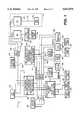
- FIG. 1is a block diagram illustrating a computer system board containing a SCSI system designed according to the present invention
- FIG. 2is a block diagram illustrating a CPU board designed to be used with the computer system board of FIG. 1;
- FIG. 3shows a simplified block diagram of the SCSI system designed according to the present invention
- FIG. 4shows a detailed schematic drawing of the SCSI termination control circuitry according to the present invention
- FIG. 5shows a simplified block diagram of one form of backplane including terminators
- FIG. 6shows a simplified block diagram of an alternative form of backplane including terminators
- FIG. 7is a simplified drawing showing the location of the SCSI terminators and connectors of the system board of FIG. 1.
- the system board S of a computer system for use according to the present inventionis shown.
- the system boardscontain circuitry and slots for receiving interchangeable circuit boards.
- the first busis the PCI or Peripheral Component Interconnect bus P which includes address/data portion 100, control and byte enable portion 102 and control signal portion 104.
- the second primary bus on the system board Sis the EISA bus E.
- the EISA bus Eincludes LA address portion 106, SA address portion 108, SD data portion 110 and EISA/ISA control signal portion 112.
- the PCI and EISA buses P and Eform the backbones of the system board S.
- a CPU connector 114is connected to the PCI bus P to receive interchangeable processor cards, such as the one shown in FIG. 2.
- a series of three PCI option connectors 118are also connected to the PCI bus P to receive any additional cards designed according to the PCI standard.
- a SCSI controller 170 contained in a SCSI subsystem 171, which is shown in more detail in FIG. 3,is connected to the PCI bus P to communicate with SCSI standard devices, such as hard drives, CD-ROMs and tape drives (not shown).
- the SCSI controller 170is an 53C825 manufactured by National Cash Register.
- the SCSI controller 170includes the capabilities necessary to act as a PCI bus master and slave and provide a SCSI bus 172.
- the SCSI devicescommunicate over the SCSI bus 172 through the SCSI connectors 122 provided on the system board S.
- a network interface (NIC) controller 120is connected to the PCI bus P.
- the controller 120includes the capabilities necessary to act as a PCI bus master and slave and the circuitry to act as an Ethernet interface.
- An Ethernet connector 124is provided on the system board S and is connected to filter and transformer circuitry 126, which in turn is connected to the controller 120. This forms a network or Ethernet connection for connecting the system boards and computer to a local area network (LAN).
- LANlocal area network
- a PCI-EISA bridge 130is provided to convert signals between the PCI bus P and the EISA bus E.
- the PCI-EISA bridge 130includes the necessary address and data buffers and latches, arbitration and bus master control logic for the PCI bus, EISA arbitration circuitry, and EISA bus controller as conventionally used in EISA systems and a DMA controller.
- the PCI-EISA bridge 130is a single integrated circuit, but other combinations are possible.
- a miscellaneous system logic chip 132is connected to the EISA bus E.
- the miscellaneous system logic chip 132contains counters and timers as conventionally present in personal computer systems, an interrupt controller for both the PCI and EISA buses P and E and power management logic, as well as other miscellaneous circuitry.
- a series of six EISA slots 134are connected to the EISA bus E to receive ISA and EISA adapter cards.
- a combination I/O chip 136is connected to the EISA bus E.
- the combination I/O chip 136preferably includes a floppy disk controller, real time clock (RTC)/CMOS memory, two UARTs, a parallel port and various address decode logic.
- a floppy disk connector 138 for receiving a cable to a floppy disk driveis connected to the combination I/O chip 136.
- a pair of serial port connectorsare also connected to the combination I/O chip 136, as is a parallel port connector 142.
- a non-volatile random access memory (NVRAM) 148is connected to the EISA bus E and receives its control signals from the combination I/O chip 136.
- An address latch 150is connected to the EISA bus E and controlled by the combination I/O chip 136 to provide additional addressing capability for the NVRAM 148.
- the NVRAM 148is used to contain certain system information.
- a data buffer 152is connected to the SD portion of the EISA bus E to provide an additional data bus XD for various additional components of the computer system.
- the NVRAM 148is connected to the XD data bus to receive its data bits.
- a flash ROM 154receives its control and address signals from the EISA bus E and is connected to the XD bus for data transfer.
- the flash ROM 154contains the BIOS information for the computer system and can be reprogrammed to allow for revisions of the BIOS.
- An 8742 or keyboard controller 156is connected to the XD bus and EISA address and control portions 108 and 112.
- the keyboard controller 156is of conventional design and is connected in turn to a keyboard connector 158 and a mouse or pointing device connector 160.
- a graphics controller 166receives its control and address from the EISA bus E and is connected to the XD bus for data transfer.
- the graphics controller 166provides video graphics to a monitor (not shown) for user interaction.
- the processor board Pis shown.
- the CPU or processor 200can be any of a plurality of processors, such as the 486DX/33, 486DX2/66, 486DX4/50-100, 486DX4/33-100, 486DX4/33-83, P24T, P54C/M, Pentium 50/75, Pentium 60/90, and Pentium 66/100, and other similar and compatible processors.
- the processor 200provides data, address and control portions 202, 204 and 206 to form a processor bus PB.
- a level 2 (L2) or external cache memory system 208is connected to the processor bus PB to provide additional caching capabilities to improve performance of the computer system.
- the L2 cache 208can be organized as a 128 kbyte direct mapped cache or 256 kbyte two-way set associative cache when used with 486 family processor and as a 256 or 512 kbyte direct mapped or two-way set associative cache when used with Pentium family processors.
- a cache and memory controller (CMC) and PCI bridge chip 210is connected to the control portion 206 and to the address portion 204.
- the CMC 210is connected to the L2 cache 208 as it incorporates the cache controller and therefore controls the operations of the cache memory devices in the L2 cache 208.
- the CMC 210is also connected to control a series of address and data buffers 212.
- the data buffers 212are utilized to handle memory data to a main memory array 214.
- the data buffers 212are connected to the processor data portion 202 and receive control signals from the CMC 210.
- the data buffers 212provide a memory address bus 216 and a memory data bus 218 to the memory array 214.
- a memory control signal bus 220 and memory address bus 216is provided from the CMC 210.
- Clock distribution and generation circuitry 222is associated with the processor card P and is connected to the CMC 210.
- a processor connector 224such as a card edge, is provided to be mateably received by the processor connector 114.
- the processor connector 224is connected to the CMC 210, the data buffers 212 and the clock distribution circuitry 222 to provide clocks to the computer system and to provide a PCI interface to allow the processor 200 to access the PCI and EISA buses P and E and to allow PCI and EISA bus masters to access the main memory array 214.
- the SCSI controller 170is shown connected to the PCI bus P and the SCSI bus 172.
- the preferred 53C825 SCSI controllerhas the capability of communicating with both wide and narrow SCSI devices on the SCSI bus 172.
- ANSIAmerican National Standards Institute
- the SCSI standardwas extended and now a SCSI-2 standard provides for several types of data transfers.
- Narrow SCSIrefers to the conventional 8-bit SCSI devices.
- Wide SCSIrefers to SCSI devices having 16 data bits.
- fast SCSIrefers to transfers that exceed the conventional SCSI standard transfer rate by allowing data transfers over the SCSI bus at up to 10 Mbyte/sec for fast-narrow SCSI and 20 Mbyte/sec for fast-wide SCSI.
- the 53C825supports all of these different types of transfers.
- the SCSI bus 172is connected to the SCSI connectors 122 for communicating with SCSI devices. More specifically, the SCSI bus 172 is connected to an external 16-bit connector 306, an internal 16-bit connector 308 and an internal 8-bit connector 310. The 16-bit connectors 306 and 308 are 68-pin SCSI connectors. The internal 8-bit connector is a 50 pin SCSI connector. Thus the SCSI bus 172 has three possible branches. Each branch will be discussed more fully below.
- Each of these connectors 306, 308 and 310receives a cable for coupling to the SCSI devices.
- each SCSI deviceis daisy-chained. So, the first SCSI device is cabled to a connector, with the next SCSI device being cabled to the first SCSI device, and so on.
- the SCSI controller 170can communicate with up to seven SCSI devices spread over the branches of the SCSI bus 172.
- the external 16-bit connector 306provides optional expansion.
- the external 16-bit connector 306receives a SCSI cable 326 if coupling to an optional SCSI device 314. It is noted that the SCSI device 314 is shown singularly, but up to seven devices can connect to the SCSI controller 170.
- An internal SCSI devicemust be utilized, so either the internal 16-bit connector 308 or the internal 8-bit connector 310 must be coupled to a SCSI device. Only one of the two may be used.
- the internal 16-bit connector 308may receive a SCSI cable 328 and the internal 8-bit connector 310 may receive a SCSI cable 330 for coupling to a backplane connector 316 and SCSI device 318 respectively. It is noted that the SCSI device 318 is shown singularly, however, up to seven devices can connect to the SCSI controller 170.
- the computer systemhas two mutually exclusive configurations for supporting internal SCSI devices.
- One alternativeis to connect the internal SCSI devices through connector 310, in which case connector 308 cannot be used. This configuration only supports narrow SCSI devices.
- the other alternativeis to connect the internal SCSI devices through a connector 308 which couples to a backplane connector 316.
- the 16-bit connector 306is capable of receiving a wide or wide-to-narrow SCSI cable 326, the wide cable transferring 16-bits of data in parallel while the wide-to-narrow cable transfers 8-bits in parallel.
- the backplanescould be located in an external chassis and then be connected to the external connector 306 using a SCSI cable.
- the SCSI standardalso defines the pinout for the SCSI connectors and cables. To keep noise minimal, multiple ground pins and signals are defined for interleaving between the SCSI signals in the cable and at the connectors. In the present invention, all of the pins defined as ground pins are not connected to ground at connectors 306, 308 and 310 as conventionally performed. At SCSI device 318 and backplane connector 316 the pins defined as ground pins are connected to ground as conventionally defined by SCSI standard.
- pins 1 and 50are not grounded but instead are connected to a termination control circuit 312 shown in detail in FIG. 4. It is noted that other typical ground pins could be used.
- pin 50iS connected to a pull-up resistor R12 in the termination control circuit 312, discussed below, by a SCSI cable external low signal, termed SC -- EXT -- LO#, and pin 1 is connected to a pull-up resistor R11 in the termination control circuit 312, discussed below, by a SCSI cable external high signal, termed SC -- EXT -- HI#.
- the SC -- EXT -- LO# and SC -- EXT -- HI# signalswill be pulled low by the grounded pins of SCSI device 314. A wide SCSI device will make contact with both signals. If a wide-to-narrow cable 326 is coupled between connector 306 and the SCSI device 314 to allow communication with narrow SCSI devices, the SC -- EXT -- LO# signal will be pulled low by the grounded pin of the narrow SCSI device, but the SC -- EXT -- HI# signal will remain high since the narrow SCSI device does not make contact with this signal. A narrow SCSI device connects only with the SC -- EXT -- LO# signal.
- the termination control circuit 312can detect the presence, or lack of presence, of either a wide or narrow SCSI configuration coupled to external 16-bit connector 306.
- internal 16-bit connector 308has a pin 50 connected to a pull-up resistor R1 in the termination control circuit 312, discussed below, by a SCSI cable internal 16 low signal, termed SC -- INT -- 16 -- LO#, and pin 1 is connected to a pull-up resistor R9 in the termination control circuit 312, discussed below, by a SCSI cable internal 16 high signal, termed SC -- INT -- 16 -- HI#. If the backplane configuration is selected and a cable 328 is coupling backplane connector 316 to internal 16-bit connector 308, then the SC -- INT -- 16 -- LO# and SC INT 16 HI# signals will be pulled low by the grounded pins of backplane connector 316.
- the termination control circuit 312could detect the presence, or lack of presence, of either a wide or narrow SCSI configuration coupled to the internal 16-bit connector 308 in that case.
- the internal 8-bit connector 310being a 50-pin SCSI connector, has a pin 22 not connected to ground as conventionally performed, but instead connected to a pull-up resistor R2 in the termination control circuit 312, discussed below, by a SCSI internal 8 signal, termed SCSI -- INT -- 8#. If a SCSI cable 330 is coupled between connector 310 and the SCSI device 318, the SCSI -- INT -- 8# signal will be pulled low by the corresponding grounded pin of SCSI device 318. If the internal 8-bit connector 310 is not used, then the SCSI -- INT -- 8# signal will remain high. Thus, the termination control circuit 312 can detect the presence, or lack or presence, of a narrow SCSI device coupled to internal 8-bit connector 310.
- a power circuit 324generates a Terminal Power signal, called TERMPWR, by connecting a current backflow diode to system power line. This is a well known circuit to provide the TERMPWR signal for the SCSI bus 172 and the terminators.
- the termination control circuit 312is shown in more detail.
- the TERMPWR signalis shown connected to one end of resistors R1, R2, R9, R10, R11, R12, R13 and R14.
- Resistors R3, R4, R5, R6, R7, R8, R15 and R16are connected to system power at one end.
- a SCSI internal enable signaltermed SCSI -- INT -- EN#, is connected to the output of an open collector inverter 418 and the second end of the resistor R8.
- the output of an open collector inverter 412is connected to the input of inverter 418 and the second end of resistor R6.
- inverter 412is connected to the input of an open collector inverter 414, the output of open collector inverter 408, the output of open collector inverter 410 and the second end of resistor R5.
- the input of inverter 408is connected to the output of open collector inverter 400 and the second end of resistor R3.
- the input to open collector inverter 400is connected to the SC -- INT -- 16 -- LO# signal, the input to open collector inverter 404, the second end of resistor R1 and one end of a capacitor C1, whose other end is connected to ground.
- the input of open collector inverter 410is connected to the output of open collector inverter 402 and the second end of resistor R4.
- inverter 402is connected to a SCSI -- INT -- 8# signal, the input of open collector inverter 406, the second end of resistor R2 and one end of capacitor C2, whose other end is connected to ground.
- SC -- INT -- 16 -- LO# signal or the SCSI -- INT -- 8# signalis driven low, the SCSI -- INT -- EN signal will be driven low or active.
- a SCSI error signaltermed SCSI -- ERROR#
- SCSI -- ERROR#is connected to the outputs of open collector inserters 414 and 416 and the second end of resistor R7.
- the input to inverter 416is connected to the outputs of open collector inserters 404 and 406 and the second end of resistor R16.
- the SCSI -- ERROR# signalindicates when this condition is not true. If both the SC -- INT -- 16 -- LO# and SCSI -- INT -- 8# signals are driven low, then the SCSI -- ERROR# signal will also be driven low, indicating an error because both internal buses are used, which is an impermissible configuration.
- a SCSI cable internal high disabled signaltermed SC -- INT -- HI -- DIS, is connected to the output of an open collector inverter 420 and the second end of resistor R10.
- the input of inverter 420is connected to the SCSI cable internal 16 high signal SC -- INT -- 16 -- HI#, the second end of resistor R9 and one end of capacitor C3, whose other end is connected to ground.
- a SCSI external enable signaltermed SCSI -- EXT -- EN#
- SCSI -- EXT -- EN#is connected to the output of an open collector inverter 426 and the second end of resistor R15.
- a SCSI cable external low disable signaltermed SC -- EXT -- LO -- DIS
- SC -- EXT -- LO -- DISis connected to the input of inverter 426, the output of an open collector inverter 424 and the second end of resistor R14.
- the SCSI cable external low SC -- EXT -- LO# signalis connected to the input of inverter 424, one end of resistor R12 and the second end of capacitor C5, whose other end is connected to ground.
- a SCSI cable external high disable signaltermed SC -- EXT -- HI -- DIS, is connected to the output of open collector inverter 422 and the second end of resistor R13.
- the SCSI cable external high signal SC -- EXT -- HI#is connected to the input of inverter 422, the second end of resistor R11 and one end of capacitor C4, whose other end is connected to ground.
- the block diagramillustrates the connection between the termination control circuit 312 and terminators 300, 302 and 304.
- the terminatorsprovide active termination of the SCSI bus 172 signal lines and have the capability to disconnect, thereby removing termination if desired.
- the terminatorsare a UC5601/03 manufactured by Unitrode Integrated Circuits.
- Terminator 300is preferably a UC5601 compatible terminator which provides termination for all required control lines and the low 8 data lines of SCSI bus 172.
- Terminator 300in place of a single UC5601 two separate UC5603 terminators could be used, as each UC5603 provides only 9 terminators and therefore two would be required to replace one UC5601.
- the termination control circuit 312provides the SC -- EXT -- HI -- DIS signal to the disable input of a terminator 302.
- the terminator 302terminates the high 8 data lines when enabled.
- the SC -- INT -- HI -- DIS signalprovided by termination control circuit 312, connects to the disable input of a terminator 304 which is preferably compatible with UC5603.
- the terminator 304terminates the high 8 data lines when enabled.
- the general locations of the connectors 306, 308 and 310, the SCSI controller 170 and the terminators 300, 302, 304 on the computer system boardare shown in FIG. 7. As can be seen, terminators 302 and 304 are both necessary as the distance between the internal and external connectors is greater than an acceptable distance from a termination point. Therefore the two terminators 302 and 304 are utilized.
- the SCSI controller 170receives the SCSI -- INT -- EN# and SCSI -- EXT -- EN# signals from the termination control circuit 312. The signals are connected to a pair of general purpose interface inputs for allowing the SCSI controller 170 and the computer system generally to detect the presence of external or internal SCSI devices.
- the SCSI -- ERROR# signalis also connected to a general purpose interface input of SCSI controller 170 for detecting the lack of an internal SCSI device.
- the seven wide SCSI backplane formis shown with a terminator 354.
- the backplane connector 316receives the SCSI -- DA(15:0), SCSI -- CONTROL, TERMPWR, SC -- INT -- 16 -- LO# and SC INT 16 HI# signals. As previously described, the SC -- INT -- 16 -- LO# and SC -- INT -- 16 -- HI# signals are grounded at the backplane connector 316.
- Seven wide SCSI connectors 340are connected to the SCSI backplane connector 316 for engaging up to seven wide SCSI devices (not shown).
- a terminator 354receives the SCSI -- DA(15:0) and SCSI -- CONTROL signals from the last wide SCSI connector 340 for terminating these signals.
- the signalsare each terminated to +2.85 volts through an individual 110 ohm resistor (not shown).
- a voltage converter 356receives the TERMPWR signal for providing the converted +2.85 volt signal to terminator 354.
- the five wide/two narrow SCSI backplane formis shown with a terminator 346.
- the backplane connector 316receives the SCSI -- D(15:0), SCSI -- CONTROL, TERMPWR, SC -- INT -- 16 -- LO# and SC -- INT -- 16 -- HI# signals.
- Five wide SCSI connectors 342are connected to the SCSI backplane connector 316 for engaging up to five wide SCSI devices (not shown).
- a 50 pin header 344is connected to the last wide SCSI connector 342 for coupling to up to two narrow SCSI devices (not shown). Only the lower eight data bits SCSI -- DA(7:0) are connected to the 50 pin header 344.
- a TRMDIS -- B signalis connected to a pin of the 50 pin header 344, the input of an inverting means 348 and one end of a resistor R20 whose second end is connected to TERMPWR.
- the output of the inverting means 348provides a DISCONNECT signal to the disable input of a terminator 346.
- the terminator 346also receives the SCSI -- DA(7:0) and SCSI -- CONTROL signals at its terminator inputs.
- a terminator 350is connected to the SCSI DA(15:8) signals for always terminating these signals. Terminator 350 terminates each signal to +2.85 volts through an individual 110 ohm resistor (not shown). A voltage converter 352 receives the TERMPWR signal for providing the converted +2.85 volt signal to terminator 350.
Landscapes
- Engineering & Computer Science (AREA)
- General Engineering & Computer Science (AREA)
- Theoretical Computer Science (AREA)
- Computer Hardware Design (AREA)
- Physics & Mathematics (AREA)
- General Physics & Mathematics (AREA)
- Bus Control (AREA)
Abstract
Description
Claims (19)
Priority Applications (1)
| Application Number | Priority Date | Filing Date | Title |
|---|---|---|---|
| US08/366,510US5613074A (en) | 1994-12-30 | 1994-12-30 | Automatic disabling of SCSI bus terminators |
Applications Claiming Priority (1)
| Application Number | Priority Date | Filing Date | Title |
|---|---|---|---|
| US08/366,510US5613074A (en) | 1994-12-30 | 1994-12-30 | Automatic disabling of SCSI bus terminators |
Publications (1)
| Publication Number | Publication Date |
|---|---|
| US5613074Atrue US5613074A (en) | 1997-03-18 |
Family
ID=23443329
Family Applications (1)
| Application Number | Title | Priority Date | Filing Date |
|---|---|---|---|
| US08/366,510Expired - LifetimeUS5613074A (en) | 1994-12-30 | 1994-12-30 | Automatic disabling of SCSI bus terminators |
Country Status (1)
| Country | Link |
|---|---|
| US (1) | US5613074A (en) |
Cited By (34)
| Publication number | Priority date | Publication date | Assignee | Title |
|---|---|---|---|---|
| US5734208A (en)* | 1996-06-14 | 1998-03-31 | Dell Usa, L.P. | Dynamic termination for signal buses going to a connector |
| US5765034A (en)* | 1995-10-20 | 1998-06-09 | International Business Machines Corporation | Fencing system for standard interfaces for storage devices |
| WO1999009485A1 (en)* | 1997-08-18 | 1999-02-25 | Nexar Technologies, Inc. | Section access for ide or scsi hard drives |
| US5892973A (en)* | 1996-11-15 | 1999-04-06 | Digital Equipment Corporation | System and method for determining attributes and coupling characteristics of components by comparatively observing provided reference signal |
| US5905888A (en)* | 1997-02-19 | 1999-05-18 | On Spec Electronic, Inc. | Bootable redundant hard disk attached to a PC's parallel port with rom-address auto-detect and configure during BIOS scan |
| US5983296A (en)* | 1995-05-02 | 1999-11-09 | Lsi Logic Corporation | Method and apparatus for terminating busses having different widths |
| US6029216A (en)* | 1997-06-27 | 2000-02-22 | Lsi Logic Corporation | Auto-termination method and apparatus for use with either active high or active low terminators |
| US6035425A (en)* | 1997-09-29 | 2000-03-07 | Lsi Logic Corporation | Testing a peripheral bus for data transfer integrity by detecting corruption of transferred data |
| US6055582A (en)* | 1998-01-16 | 2000-04-25 | Compaq Computer Corporation | SCSI duplex-ready backplane for selectively enabling SCSI simplex and duplex modes based on indication of desired SCSI mode |
| US6061806A (en)* | 1997-05-12 | 2000-05-09 | Lsi Logic Corporation | Method and apparatus for maintaining automatic termination of a bus in the event of a host failure |
| US6070206A (en)* | 1997-03-31 | 2000-05-30 | Lsi Logic Corporation | Method and apparatus for terminating a bus |
| US6078979A (en)* | 1998-06-19 | 2000-06-20 | Dell Usa, L.P. | Selective isolation of a storage subsystem bus utilzing a subsystem controller |
| US6092131A (en)* | 1997-07-28 | 2000-07-18 | Lsi Logic Corporation | Method and apparatus for terminating a bus at a device interface |
| US6108740A (en)* | 1998-10-14 | 2000-08-22 | Lsi Logic Corporation | Method and apparatus for terminating a bus such that stub length requirements are met |
| US6188973B1 (en) | 1996-11-15 | 2001-02-13 | Compaq Computer Corporation | Automatic mapping, monitoring, and control of computer room components |
| US6192433B1 (en)* | 1998-07-14 | 2001-02-20 | Tandem Computers Incorporated | Automatic SCSI termination readjustment |
| US20020056018A1 (en)* | 2000-09-08 | 2002-05-09 | Schumacher Matthew J. | Method and apparatus implementing a tuned stub SCSI topology |
| US6425025B1 (en)* | 1999-06-03 | 2002-07-23 | Dell Usa, L.P. | System and method for connecting electronic circuitry in a computer system |
| US6438639B1 (en)* | 1996-08-27 | 2002-08-20 | International Business Machines Corporation | Computer system bus network providing concurrent communication and connection transition of peripheral devices |
| US6480925B1 (en)* | 1996-01-11 | 2002-11-12 | Computer Performance, Inc. | Compact and versatile SCA to SCSI bus adapter |
| US6487613B1 (en)* | 1999-10-14 | 2002-11-26 | Dell Products L.P. | System for indicating channel availability by having a light emitting diode operative to signal of connection of a data storage device to an internal connector |
| US6493785B1 (en) | 1999-02-19 | 2002-12-10 | Compaq Information Technologies Group, L.P. | Communication mode between SCSI devices |
| US6510532B1 (en)* | 1998-10-15 | 2003-01-21 | Hewlett-Packard Company | Bus and/or interface local capture module for diagnostic analyzer |
| US6546445B1 (en)* | 2000-01-13 | 2003-04-08 | Dell Usa, L.P. | Method and system for connecting dual storage interfaces |
| US6546497B1 (en) | 1999-02-19 | 2003-04-08 | Hewlett-Packard Development Company, L.P. | SCSI clock stretching |
| US6546444B2 (en)* | 2000-09-08 | 2003-04-08 | Hewlett-Packard Development Company, L.P. | Tuned stub, SCSI topology |
| US6557064B1 (en) | 1999-02-19 | 2003-04-29 | Hewlett-Packard Development Company | Set up time adjust |
| US6636921B1 (en) | 1999-02-19 | 2003-10-21 | Hewlett-Packard Development Company, Lp. | SCSI repeater circuit with SCSI address translation and enable |
| US6675244B1 (en) | 1999-02-19 | 2004-01-06 | Hewlett-Packard Development Company, L.P. | SCSI data rate speed determination |
| US20040071097A1 (en)* | 1998-11-30 | 2004-04-15 | Halter Richard A. | J1850 application specific integrated circuit (ASIC) and messaging technique |
| US6731132B2 (en) | 2002-06-20 | 2004-05-04 | Texas Instruments Incorporated | Programmable line terminator |
| US20040088616A1 (en)* | 2002-07-11 | 2004-05-06 | Vuong Vinh T. | Multi-mode SCSI backplane and detection logic |
| US20110078336A1 (en)* | 2009-09-29 | 2011-03-31 | Micron Technology, Inc. | State change in systems having devices coupled in a chained configuration |
| US20120026018A1 (en)* | 2010-07-29 | 2012-02-02 | Getac Technology Corporation | Apparatus for detecting bus connection |
Citations (18)
| Publication number | Priority date | Publication date | Assignee | Title |
|---|---|---|---|---|
| US4320508A (en)* | 1979-04-06 | 1982-03-16 | Fuji Electric Co., Ltd. | Self-diagnosing, self-correcting communications network |
| US4402082A (en)* | 1980-10-31 | 1983-08-30 | Foster Wheeler Energy Corporation | Automatic line termination in distributed industrial process control system |
| GB2168574A (en)* | 1984-12-15 | 1986-06-18 | Stc Plc | Transmission system |
| US4920339A (en)* | 1989-01-06 | 1990-04-24 | Western Digital Corp. | Switchable bus termination and address selector |
| USRE33521E (en)* | 1981-04-03 | 1991-01-15 | Hitachi, Ltd. | Method and apparatus for detecting a faulty computer in a multicomputer system |
| JPH0316445A (en)* | 1989-06-14 | 1991-01-24 | Fujitsu Ltd | Termination method |
| JPH0323706A (en)* | 1989-06-21 | 1991-01-31 | Nec Corp | Signal termination circuit |
| US5033049A (en)* | 1989-06-12 | 1991-07-16 | International Business Machines Corporation | On-board diagnostic sub-system for SCSI interface |
| US5120909A (en)* | 1991-04-26 | 1992-06-09 | Ag Communication Systems Corporation | Terminating devices detection and verification circuit |
| JPH04247742A (en)* | 1991-02-01 | 1992-09-03 | Fujitsu Ltd | Bus line termination system |
| US5272396A (en)* | 1991-09-05 | 1993-12-21 | Unitrode Corporation | Controllable bus terminator with voltage regulation |
| US5309569A (en)* | 1992-04-24 | 1994-05-03 | Digital Equipment Corporation | Self-configuring bus termination component |
| US5313595A (en)* | 1992-12-10 | 1994-05-17 | Digital Equipment Corporation | Automatic signal termination system for a computer bus |
| US5357519A (en)* | 1991-10-03 | 1994-10-18 | Apple Computer, Inc. | Diagnostic system |
| US5434516A (en)* | 1993-07-09 | 1995-07-18 | Future Domain Corporation | Automatic SCSI termination circuit |
| JP3016445U (en) | 1995-03-31 | 1995-10-03 | 茂樹 佐野 | Back traveling device in cultivator |
| US5467453A (en)* | 1993-07-20 | 1995-11-14 | Dell Usa, L.P. | Circuit for providing automatic SCSI bus termination |
| JP3023706U (en) | 1995-10-12 | 1996-04-30 | 株式会社渋谷製作所 | Fluid leakage prevention seal |
- 1994
- 1994-12-30USUS08/366,510patent/US5613074A/ennot_activeExpired - Lifetime
Patent Citations (23)
| Publication number | Priority date | Publication date | Assignee | Title |
|---|---|---|---|---|
| US4320508A (en)* | 1979-04-06 | 1982-03-16 | Fuji Electric Co., Ltd. | Self-diagnosing, self-correcting communications network |
| US4402082A (en)* | 1980-10-31 | 1983-08-30 | Foster Wheeler Energy Corporation | Automatic line termination in distributed industrial process control system |
| USRE33521E (en)* | 1981-04-03 | 1991-01-15 | Hitachi, Ltd. | Method and apparatus for detecting a faulty computer in a multicomputer system |
| GB2168574A (en)* | 1984-12-15 | 1986-06-18 | Stc Plc | Transmission system |
| US4920339A (en)* | 1989-01-06 | 1990-04-24 | Western Digital Corp. | Switchable bus termination and address selector |
| US5033049A (en)* | 1989-06-12 | 1991-07-16 | International Business Machines Corporation | On-board diagnostic sub-system for SCSI interface |
| JPH0316445A (en)* | 1989-06-14 | 1991-01-24 | Fujitsu Ltd | Termination method |
| JPH0323706A (en)* | 1989-06-21 | 1991-01-31 | Nec Corp | Signal termination circuit |
| JPH04247742A (en)* | 1991-02-01 | 1992-09-03 | Fujitsu Ltd | Bus line termination system |
| US5120909A (en)* | 1991-04-26 | 1992-06-09 | Ag Communication Systems Corporation | Terminating devices detection and verification circuit |
| US5272396A (en)* | 1991-09-05 | 1993-12-21 | Unitrode Corporation | Controllable bus terminator with voltage regulation |
| US5338979A (en)* | 1991-09-05 | 1994-08-16 | Unitrode Corporation | Controllable bus terminator |
| US5272396B1 (en)* | 1991-09-05 | 1996-02-13 | Unitrode Corp | Controllable bus terminator with voltage regulation |
| US5338979B1 (en)* | 1991-09-05 | 1996-02-13 | Unitrode Corp | Controllable bus terminator |
| US5272396B2 (en)* | 1991-09-05 | 1996-11-26 | Unitrode Corp | Controllable bus terminator with voltage regulation |
| US5338979B2 (en)* | 1991-09-05 | 1996-11-26 | Unitrode Corp | Controllable bus terminator |
| US5357519A (en)* | 1991-10-03 | 1994-10-18 | Apple Computer, Inc. | Diagnostic system |
| US5309569A (en)* | 1992-04-24 | 1994-05-03 | Digital Equipment Corporation | Self-configuring bus termination component |
| US5313595A (en)* | 1992-12-10 | 1994-05-17 | Digital Equipment Corporation | Automatic signal termination system for a computer bus |
| US5434516A (en)* | 1993-07-09 | 1995-07-18 | Future Domain Corporation | Automatic SCSI termination circuit |
| US5467453A (en)* | 1993-07-20 | 1995-11-14 | Dell Usa, L.P. | Circuit for providing automatic SCSI bus termination |
| JP3016445U (en) | 1995-03-31 | 1995-10-03 | 茂樹 佐野 | Back traveling device in cultivator |
| JP3023706U (en) | 1995-10-12 | 1996-04-30 | 株式会社渋谷製作所 | Fluid leakage prevention seal |
Non-Patent Citations (9)
| Title |
|---|
| Notebook Small Computer System Interface 2, Working Draft, X3T9.2 Project 375D, printed Sep. 7, 1993.* |
| Notebook--Small Computer System Interface--2, Working Draft, X3T9.2 Project 375D, printed Sep. 7, 1993. |
| Unitrode Integrated Circuits 9 Line SCSI Activer Terminator (UC5603), Sep. 1994.* |
| Unitrode Integrated Circuits 9-Line SCSI Activer Terminator (UC5603), Sep. 1994. |
| Unitrode Integrated Circuits SCSI Activer Terminator (UC5601), Sep. 1994.* |
| X3T10/1071D draft proposed American National Standard for Information Systems SCSI 3 Fast 20, revision 6 (Oct., 1994).* |
| X3T10/1071D draft proposed American National Standard for Information Systems--SCSI-3 Fast-20, revision 6 (Oct., 1994). |
| X3T10/855D draft proposed American National Standard Information Technology SCSI 3 Parallel Interface, revision 15a (Feb., 1992).* |
| X3T10/855D draft proposed American National Standard Information Technology--SCSI-3 Parallel Interface, revision 15a (Feb., 1992). |
Cited By (44)
| Publication number | Priority date | Publication date | Assignee | Title |
|---|---|---|---|---|
| US5983296A (en)* | 1995-05-02 | 1999-11-09 | Lsi Logic Corporation | Method and apparatus for terminating busses having different widths |
| US5765034A (en)* | 1995-10-20 | 1998-06-09 | International Business Machines Corporation | Fencing system for standard interfaces for storage devices |
| US6480925B1 (en)* | 1996-01-11 | 2002-11-12 | Computer Performance, Inc. | Compact and versatile SCA to SCSI bus adapter |
| US5734208A (en)* | 1996-06-14 | 1998-03-31 | Dell Usa, L.P. | Dynamic termination for signal buses going to a connector |
| US6438639B1 (en)* | 1996-08-27 | 2002-08-20 | International Business Machines Corporation | Computer system bus network providing concurrent communication and connection transition of peripheral devices |
| US5892973A (en)* | 1996-11-15 | 1999-04-06 | Digital Equipment Corporation | System and method for determining attributes and coupling characteristics of components by comparatively observing provided reference signal |
| US6188973B1 (en) | 1996-11-15 | 2001-02-13 | Compaq Computer Corporation | Automatic mapping, monitoring, and control of computer room components |
| US5905888A (en)* | 1997-02-19 | 1999-05-18 | On Spec Electronic, Inc. | Bootable redundant hard disk attached to a PC's parallel port with rom-address auto-detect and configure during BIOS scan |
| US6070206A (en)* | 1997-03-31 | 2000-05-30 | Lsi Logic Corporation | Method and apparatus for terminating a bus |
| US6061806A (en)* | 1997-05-12 | 2000-05-09 | Lsi Logic Corporation | Method and apparatus for maintaining automatic termination of a bus in the event of a host failure |
| US6029216A (en)* | 1997-06-27 | 2000-02-22 | Lsi Logic Corporation | Auto-termination method and apparatus for use with either active high or active low terminators |
| US6092131A (en)* | 1997-07-28 | 2000-07-18 | Lsi Logic Corporation | Method and apparatus for terminating a bus at a device interface |
| WO1999009485A1 (en)* | 1997-08-18 | 1999-02-25 | Nexar Technologies, Inc. | Section access for ide or scsi hard drives |
| US6035425A (en)* | 1997-09-29 | 2000-03-07 | Lsi Logic Corporation | Testing a peripheral bus for data transfer integrity by detecting corruption of transferred data |
| US6055582A (en)* | 1998-01-16 | 2000-04-25 | Compaq Computer Corporation | SCSI duplex-ready backplane for selectively enabling SCSI simplex and duplex modes based on indication of desired SCSI mode |
| US6078979A (en)* | 1998-06-19 | 2000-06-20 | Dell Usa, L.P. | Selective isolation of a storage subsystem bus utilzing a subsystem controller |
| US6192433B1 (en)* | 1998-07-14 | 2001-02-20 | Tandem Computers Incorporated | Automatic SCSI termination readjustment |
| US6108740A (en)* | 1998-10-14 | 2000-08-22 | Lsi Logic Corporation | Method and apparatus for terminating a bus such that stub length requirements are met |
| US6510532B1 (en)* | 1998-10-15 | 2003-01-21 | Hewlett-Packard Company | Bus and/or interface local capture module for diagnostic analyzer |
| US20040071097A1 (en)* | 1998-11-30 | 2004-04-15 | Halter Richard A. | J1850 application specific integrated circuit (ASIC) and messaging technique |
| US7283488B2 (en) | 1998-11-30 | 2007-10-16 | Chrysler Llc | J1850 application specific integrated circuit (ASIC) and messaging technique |
| US6493785B1 (en) | 1999-02-19 | 2002-12-10 | Compaq Information Technologies Group, L.P. | Communication mode between SCSI devices |
| US6546497B1 (en) | 1999-02-19 | 2003-04-08 | Hewlett-Packard Development Company, L.P. | SCSI clock stretching |
| US6557064B1 (en) | 1999-02-19 | 2003-04-29 | Hewlett-Packard Development Company | Set up time adjust |
| US6636921B1 (en) | 1999-02-19 | 2003-10-21 | Hewlett-Packard Development Company, Lp. | SCSI repeater circuit with SCSI address translation and enable |
| US6675244B1 (en) | 1999-02-19 | 2004-01-06 | Hewlett-Packard Development Company, L.P. | SCSI data rate speed determination |
| US6425025B1 (en)* | 1999-06-03 | 2002-07-23 | Dell Usa, L.P. | System and method for connecting electronic circuitry in a computer system |
| US6487613B1 (en)* | 1999-10-14 | 2002-11-26 | Dell Products L.P. | System for indicating channel availability by having a light emitting diode operative to signal of connection of a data storage device to an internal connector |
| US6546445B1 (en)* | 2000-01-13 | 2003-04-08 | Dell Usa, L.P. | Method and system for connecting dual storage interfaces |
| US20020056018A1 (en)* | 2000-09-08 | 2002-05-09 | Schumacher Matthew J. | Method and apparatus implementing a tuned stub SCSI topology |
| US6546444B2 (en)* | 2000-09-08 | 2003-04-08 | Hewlett-Packard Development Company, L.P. | Tuned stub, SCSI topology |
| US7103694B2 (en)* | 2000-09-08 | 2006-09-05 | Hewlett-Packard Development Company, L.P. | Method and apparatus implementing a tuned stub SCSI topology |
| US6731132B2 (en) | 2002-06-20 | 2004-05-04 | Texas Instruments Incorporated | Programmable line terminator |
| US20040088616A1 (en)* | 2002-07-11 | 2004-05-06 | Vuong Vinh T. | Multi-mode SCSI backplane and detection logic |
| US6901458B2 (en) | 2002-07-11 | 2005-05-31 | Hewlett-Packard Development Company, L.P. | Multi-mode SCSI backplane and detection logic |
| US20110078336A1 (en)* | 2009-09-29 | 2011-03-31 | Micron Technology, Inc. | State change in systems having devices coupled in a chained configuration |
| US8271697B2 (en) | 2009-09-29 | 2012-09-18 | Micron Technology, Inc. | State change in systems having devices coupled in a chained configuration |
| US8539117B2 (en) | 2009-09-29 | 2013-09-17 | Micron Technology, Inc. | State change in systems having devices coupled in a chained configuration |
| US9075765B2 (en) | 2009-09-29 | 2015-07-07 | Micron Technology, Inc. | State change in systems having devices coupled in a chained configuration |
| US9235343B2 (en) | 2009-09-29 | 2016-01-12 | Micron Technology, Inc. | State change in systems having devices coupled in a chained configuration |
| US10089250B2 (en) | 2009-09-29 | 2018-10-02 | Micron Technology, Inc. | State change in systems having devices coupled in a chained configuration |
| US10762003B2 (en) | 2009-09-29 | 2020-09-01 | Micron Technology, Inc. | State change in systems having devices coupled in a chained configuration |
| US20120026018A1 (en)* | 2010-07-29 | 2012-02-02 | Getac Technology Corporation | Apparatus for detecting bus connection |
| US8279093B2 (en)* | 2010-07-29 | 2012-10-02 | Getac Technology Corporation | Apparatus for detecting bus connection |
Similar Documents
| Publication | Publication Date | Title |
|---|---|---|
| US5613074A (en) | Automatic disabling of SCSI bus terminators | |
| US5751977A (en) | Wide SCSI bus controller with buffered acknowledge signal | |
| US5835784A (en) | System for booting processor from remote memory by preventing host processor from configuring an environment of processor while configuring an interface unit between processor and remote memory | |
| US6256691B1 (en) | Universal docking station | |
| US6845420B2 (en) | System for supporting both serial and parallel storage devices on a connector | |
| US6292859B1 (en) | Automatic selection of an upgrade controller in an expansion slot of a computer system motherboard having an existing on-board controller | |
| US5923860A (en) | Apparatus, method and system for remote peripheral component interconnect bus using accelerated graphics port logic circuits | |
| US5892964A (en) | Computer bridge interfaces for accelerated graphics port and peripheral component interconnect devices | |
| US5727184A (en) | Method and apparatus for interfacing between peripherals of multiple formats and a single system bus | |
| US5619659A (en) | System for extending ISA bus without using dedicated device driver software by using E2 P2 interface which provides multiplexed bus signal through standard parallel port connector | |
| US5561772A (en) | Expansion bus system for replicating an internal bus as an external bus with logical interrupts replacing physical interrupt lines | |
| US6519669B1 (en) | Apparatus and method of connecting a computer and a peripheral device | |
| US5761527A (en) | PCI bus hard disk activity LED circuit | |
| US5701514A (en) | System providing user definable selection of different data transmission modes of drivers of an I/O controller transmitting to peripherals with different data transmission rate | |
| CN1233799A (en) | PCI and adapter requirements after reset | |
| WO1996017302A1 (en) | Bridge between two buses | |
| EP0775959B1 (en) | Method and apparatus for optimizing PCI interrupt binding and associated latency in extended/bridged PCI busses | |
| EP0836141B1 (en) | A fault-tolerant bus system | |
| CN112988637A (en) | Promotion and I2C backward compatible I3C hub | |
| US6523071B1 (en) | Process and apparatus for configuring the direct memory access transfer mode of a motherboard or host computer | |
| WO1996008773A2 (en) | Pcmcia dma data bus mastering | |
| US6567880B1 (en) | Computer bridge interfaces for accelerated graphics port and peripheral component interconnect devices | |
| US6065079A (en) | Apparatus for switching a bus power line to a peripheral device to ground in response to a signal indicating single ended configuration of the bus | |
| US5764925A (en) | Multiple long bus architecture having a non-terminal termination arrangement | |
| US6457089B1 (en) | Microprocessor bus structure |
Legal Events
| Date | Code | Title | Description |
|---|---|---|---|
| AS | Assignment | Owner name:COMPAQ COMPUTER CORPORATION Free format text:ASSIGNMENT OF ASSIGNORS INTEREST;ASSIGNOR:GALLOWAY, WILLIAM C.;REEL/FRAME:007418/0052 Effective date:19950315 | |
| FEPP | Fee payment procedure | Free format text:PAYOR NUMBER ASSIGNED (ORIGINAL EVENT CODE: ASPN); ENTITY STATUS OF PATENT OWNER: LARGE ENTITY | |
| STCF | Information on status: patent grant | Free format text:PATENTED CASE | |
| FPAY | Fee payment | Year of fee payment:4 | |
| FEPP | Fee payment procedure | Free format text:PAYOR NUMBER ASSIGNED (ORIGINAL EVENT CODE: ASPN); ENTITY STATUS OF PATENT OWNER: LARGE ENTITY Free format text:PAYER NUMBER DE-ASSIGNED (ORIGINAL EVENT CODE: RMPN); ENTITY STATUS OF PATENT OWNER: LARGE ENTITY | |
| AS | Assignment | Owner name:COMPAQ INFORMATION TECHNOLOGIES GROUP, L.P., TEXAS Free format text:ASSIGNMENT OF ASSIGNORS INTEREST;ASSIGNOR:COMPAQ COMPUTER CORPORATION;REEL/FRAME:012418/0222 Effective date:20010620 | |
| AS | Assignment | Owner name:HEWLETT-PACKARD DEVELOPMENT COMPANY, L.P., TEXAS Free format text:CHANGE OF NAME;ASSIGNOR:COMPAQ INFORMATION TECHNOLOGIES GROUP, LP;REEL/FRAME:015000/0305 Effective date:20021001 | |
| FPAY | Fee payment | Year of fee payment:8 | |
| FPAY | Fee payment | Year of fee payment:12 |