US5612890A - System and method for controlling product dispensation utilizing metered valve apparatus and electronic interconnection map corresponding to plumbing interconnections - Google Patents
System and method for controlling product dispensation utilizing metered valve apparatus and electronic interconnection map corresponding to plumbing interconnectionsDownload PDFInfo
- Publication number
- US5612890A US5612890AUS08/445,053US44505395AUS5612890AUS 5612890 AUS5612890 AUS 5612890AUS 44505395 AUS44505395 AUS 44505395AUS 5612890 AUS5612890 AUS 5612890A
- Authority
- US
- United States
- Prior art keywords
- fluid
- central controller
- block
- dispensing
- conduit
- Prior art date
- Legal status (The legal status is an assumption and is not a legal conclusion. Google has not performed a legal analysis and makes no representation as to the accuracy of the status listed.)
- Expired - Fee Related
Links
- 238000000034methodMethods0.000titleclaimsabstractdescription40
- 238000009428plumbingMethods0.000titleclaimsabstractdescription7
- 239000012530fluidSubstances0.000claimsabstractdescription154
- 230000006854communicationEffects0.000claimsabstractdescription32
- 238000004891communicationMethods0.000claimsabstractdescription30
- 230000004044responseEffects0.000claimsabstractdescription25
- 238000013475authorizationMethods0.000claimsabstractdescription21
- 230000005540biological transmissionEffects0.000claimsabstractdescription11
- 230000001276controlling effectEffects0.000claimsdescription15
- 230000008859changeEffects0.000claimsdescription12
- 239000010705motor oilSubstances0.000claimsdescription10
- 239000000463materialSubstances0.000claimsdescription6
- 230000000977initiatory effectEffects0.000claimsdescription5
- 230000000007visual effectEffects0.000claimsdescription5
- 230000001105regulatory effectEffects0.000claimsdescription3
- 239000000446fuelSubstances0.000claimsdescription2
- 239000013590bulk materialSubstances0.000claims3
- 230000008878couplingEffects0.000claims1
- 238000010168coupling processMethods0.000claims1
- 238000005859coupling reactionMethods0.000claims1
- 230000008054signal transmissionEffects0.000claims1
- 238000010586diagramMethods0.000description68
- 239000010432diamondSubstances0.000description45
- 229910003460diamondInorganic materials0.000description44
- 238000012545processingMethods0.000description29
- 230000008569processEffects0.000description26
- 230000006870functionEffects0.000description22
- 238000005086pumpingMethods0.000description14
- 238000012360testing methodMethods0.000description7
- 239000003921oilSubstances0.000description5
- 238000009434installationMethods0.000description2
- 230000008439repair processEffects0.000description2
- 210000003813thumbAnatomy0.000description2
- 206010019233HeadachesDiseases0.000description1
- 230000007175bidirectional communicationEffects0.000description1
- 239000003086colorantSubstances0.000description1
- 238000004590computer programMethods0.000description1
- 230000001186cumulative effectEffects0.000description1
- 238000013479data entryMethods0.000description1
- 230000001934delayEffects0.000description1
- 238000002405diagnostic procedureMethods0.000description1
- 239000002283diesel fuelSubstances0.000description1
- 239000003502gasolineSubstances0.000description1
- 231100000869headacheToxicity0.000description1
- 238000012423maintenanceMethods0.000description1
- 230000007246mechanismEffects0.000description1
- 238000012986modificationMethods0.000description1
- 230000004048modificationEffects0.000description1
- 238000012544monitoring processMethods0.000description1
- 230000000737periodic effectEffects0.000description1
- 239000003208petroleumSubstances0.000description1
- 238000012913prioritisationMethods0.000description1
- 230000009467reductionEffects0.000description1
- 239000007787solidSubstances0.000description1
- 238000005507sprayingMethods0.000description1
- 230000001960triggered effectEffects0.000description1
Images


Classifications
- B—PERFORMING OPERATIONS; TRANSPORTING
- B67—OPENING, CLOSING OR CLEANING BOTTLES, JARS OR SIMILAR CONTAINERS; LIQUID HANDLING
- B67D—DISPENSING, DELIVERING OR TRANSFERRING LIQUIDS, NOT OTHERWISE PROVIDED FOR
- B67D7/00—Apparatus or devices for transferring liquids from bulk storage containers or reservoirs into vehicles or into portable containers, e.g. for retail sale purposes
- B67D7/04—Apparatus or devices for transferring liquids from bulk storage containers or reservoirs into vehicles or into portable containers, e.g. for retail sale purposes for transferring fuels, lubricants or mixed fuels and lubricants
- B—PERFORMING OPERATIONS; TRANSPORTING
- B67—OPENING, CLOSING OR CLEANING BOTTLES, JARS OR SIMILAR CONTAINERS; LIQUID HANDLING
- B67D—DISPENSING, DELIVERING OR TRANSFERRING LIQUIDS, NOT OTHERWISE PROVIDED FOR
- B67D7/00—Apparatus or devices for transferring liquids from bulk storage containers or reservoirs into vehicles or into portable containers, e.g. for retail sale purposes
- B67D7/06—Details or accessories
- B67D7/08—Arrangements of devices for controlling, indicating, metering or registering quantity or price of liquid transferred
- B67D7/14—Arrangements of devices for controlling, indicating, metering or registering quantity or price of liquid transferred responsive to input of recorded programmed information, e.g. on punched cards
- B67D7/145—Arrangements of devices for controlling, indicating, metering or registering quantity or price of liquid transferred responsive to input of recorded programmed information, e.g. on punched cards by wireless communication means, e.g. RF, transponders or the like
Definitions
- the inventionrelates to a controlled, remote dispensation of fluids and other materials and, more particularly, to a method and system for controlling a dispensation of fluids including a remote communication link between a central controller and at least one metered valve apparatus.
- fluidssuch as motor oil and transmission fluid are stored in bulk and are dispensed for use in individual vehicles.
- each of the bulk fluid tanksare coupled to individual work stations or bays by flow lines including a metering device.
- a metering deviceassociated with each work station or bay is an electrically operated valve and a manual valve.
- a thumb wheel electromechanical deviceis set to the number of quarts of fluid (such as oil) to be dispensed, and the electromagnetic valve associated with one bay is opened. Wires extend from the Parts Department to the electrical valve at each work station or bay, to provide actuation of the electrical valve, thus enabling fluid flow to the selected work station or bay.
- the metering devicesends signals back to the thumb wheel device, successively stepping it toward zero as the oil is dispensed.
- the electrical valveis closed and oil flow is stopped.
- the foregoing relatively primitive systeminvolves the need for telephone calls from the work station to the Parts Shop or vice versa when the dispense operation is completed, and delays when the mechanics at several bays are requesting the dispensing, of fluids, or do not promptly dispense fluid following energization of the electromagnetic valves. Further, because no automatic record is made of the fluid dispensing, many facilities have encountered very substantial losses of valuable fluids, both during and after office hours.
- Prior artuses a manually-operated controller.
- the operatoruses a switch to select which station to pump to. This selects both the service bay and the fluid dispensed.
- the controllerthen counts clicks from a flow meter in that line.
- the only intelligence in the systemis the control operator who must queue the jobs and determine when the job has finished pumping (the full quantity may not actually be needed, as when a transmission is being topped off).
- the operatorusually has no visibility when a technician has stopped pumping short of the specified quantity.
- the operatoralso does not know if a technician requesting a dispense has walked away from the dispensing station or otherwise abandoned the requisite dispense.
- the operatoris responsible for billing the correct amount of fluid to the correct job, a task which is often imprecisely performed at best.
- Present systemsdo not maintain or provide any inventory information. In fact, present systems will initiate a dispense even if there is no fluid in the tank to dispense.
- an object of the present inventionis to provide a method and system for controlling a dispensing of fluids characterized by the following advantageous features:
- the control PCis linked by radio or telephone to the Remote Controllers (RCs), eliminating a large wiring headache between buildings.
- RCsRemote Controllers
- Buildingsmay be separated from the Control point by up to a mile or so with radio-interconnect, or by many miles with telephone interconnect.
- Intelligencecomputers are placed at two points in the system, greatly reducing operator workload and attention, and avoiding dependence on operator memory.
- Power interruption at the Control PCdoes not interrupt or interfere with already-authorized dispenses.
- the RCwill finish them and retain the results in memory until the Control PC comes back on-line.
- Power interruptions at the RCwill cause temporary interruption of operating dispenses because of lose of control of valves and pumps, but the system can be made to pick up where it left off when power is restored.
- Pumpscan be started and stopped with each dispense, or the system can automatically accommodate a "pumps-always-on" system.
- This systemcan provide 1/20th quart visibility if symmetric-switched flow meters (equal on and off times) are used.
- a current inventoryonce entered by the operator, is maintained by the system, with re-order indications to the operator at user-controlled inventory points. A dispense cannot be initiated without sufficient inventory on hand.
- the systemprovides password protection at several levels. Each dispense must be authorized by a named person, which is recorded.
- the systeminterconnects with the user's fire alarm system, providing automatic shutdown of all pumping in a building which experiences a fire. All fluid dispensed at the time of a fire-induced shutdown is still reported to the Control PC, but pumps and valves are turned off to prevent spraying fire-enhancing fluids from ruptured lines.
- an automatic fire-extinguishing systemmay be activated by an RC whose alarm is triggered.
- a system for controlling a dispensing of materials such as fluidsincludes at least one metered quantity control apparatus such as a valve apparatus, a central controller and a remote communication link therebetween.
- the valve apparatuscontrols a movement of fluid from at least one bulk fluid reservoir through at least one conduit in response to an authorization signal.
- the central controllerestablishes an electronic interconnection "map" corresponding to plumbing interconnections between the at least one bulk fluid reservoir and the at least one fluid conduit.
- the central processoremploys the electronic interconnection map to generate the authorization signal which is provided from the central processor to at least one metered valve apparatus via the remote communication link.
- the at least one metered valve apparatusgenerates fluid dispensing signals (indicating quantities of fluid flow) in response to movement of the fluid through the at least one conduit.
- the central controllerfurther employs the fluid dispensing signals to generate the authorization signal.
- the central controllerincludes a storage device for storing system configuration information and transaction records including the electronic interconnection map.
- the systemfurther includes an operator interface to the central controller for initiating a configuration change to the system configuration information or for providing a visual indication of the system configuration information and the transaction records.
- a method for controlling the dispensing of a fluidincludes the steps of:
- each stationincluding at least one fluid dispensing conduit, at least one metered valve apparatus for regulating movement of fluids through the at least one fluid dispensing conduit and a processor for controlling the at least one metered valve apparatus, each processor being electrically connected to the central controller via a communication link;
- system configuration information and transaction recordsincluding an electronic fluid-station interconnection map corresponding to fluid-station plumbing interconnections between the at least one fluid and the at least one dispensing station;
- the scheme described hereinis a method for remote control of such operations or processes as dispensing fluids, solids, or other materials, or exercising remote control of systems.
- the method describeddoes away with the extensive wiring between the point at which the operator exercises control, and the building or place where that control is exerted. It also automates much of the operation, freeing the operator of constant monitoring once the operation has been started. It also contains security features which prevent unauthorized removal of inventory and provides extensive record-keeping of inventory increases and reductions, up-to-the-second inventories, and inventory re-order warnings.
- FIG. 1is a block diagram of the remote control system of the present invention
- FIG. 2is a partial block diagram and partial perspective view of the system for controlling a dispensation of fluids
- FIGS. 3A, 3B, 3Care an overview block diagram of the PC control program
- FIG. 4is a detailed block diagram of the PC control program start up, comm check and stranded job processing routines
- FIG. 5is a block diagram of the PC control program main menu
- FIG. 6is a detailed block diagram of the PC control program show job queue menu
- FIG. 7is a detailed block diagram of the PC control program display stations subroutine
- FIG. 8is a detailed block diagram of the PC control program display fluids subroutine
- FIG. 9is a detailed block diagram of the PC control program display technicians subroutine
- FIG. 10is a detailed block diagram of the PC control program display operations subroutine
- FIG. 11is a detailed block diagram of the PC control program close jobs subroutine
- FIG. 12is a detailed block diagram of the PC control program delete jobs subroutine
- FIG. 13is a detailed block diagram of the PC control program add jobs subroutine
- FIG. 14is a detailed block diagram of the PC control program modify jobs subroutine
- FIG. 15is a detailed block diagram of the PC control program "menus" menu
- FIG. 16is a detailed block diagram of the PC control program menu A subroutine
- FIG. 17is a detailed block diagram of the PC control program menu B subroutine
- FIG. 18is a detailed block diagram of the PC control program menu C subroutine
- FIG. 19is a detailed block diagram of the PC control program system menu
- FIG. 20is a detailed block diagram of the PC control program exit routine
- FIG. 21is a detailed block diagram of the PC control program communications interrupt
- FIG. 22is a detailed block diagram of the remote controller start up procedure
- FIG. 23is a block diagram of the remote controller scheduler
- FIG. 24is a detailed block diagram of the remote controller meter polling subroutine
- FIG. 25is a detailed block diagram of the remote controller subtask scheduler subroutine
- FIG. 26is a detailed block diagram of the remote controller PC-incoming message processing subroutine
- FIG. 27is a detailed block diagram of the remote controller PC-command processing subroutine
- FIG. 28is a detailed block diagram of the remote controller PC-outgoing message processing subroutine
- FIG. 29is a detailed block diagram of the remote controller response message processing subroutine
- FIG. 30is a detailed block diagram of the remote controller chain-incoming message processing subroutine
- FIG. 31is a detailed block diagram of the remote controller chain-outgoing message processing subroutine
- FIG. 32is a detailed block diagram of the remote controller background tasks subroutine
- FIG. 33is a detailed block diagram of the remote controller new job start subroutine
- FIG. 34is a detailed block diagram of the remote controller serial interrupt from PC port
- FIG. 35is a detailed block diagram of the remote controller serial interrupt from chain port.
- FIG. 36is a detailed block diagram of the remote controller one second time tick interrupt.
- FIG. 1is a block diagram of a remote control system 50.
- the basic system 50consists of one or more personal computers, designated as PC1 through PCn, each of which is connected to a wireless modem 54, designated as WMp1 through WMpn, or to one or more telephone lines through telephone modems.
- a wireless modem 54designated as WMp1 through WMpn
- RC1 through RCnAt the other end of the radio or telephone link is one or more Remote Controllers 56, designated as RC1 through RCn.
- the PC computers 52include and provide interface(s) with the human operator(s) who control the system.
- the PC computers 52execute a control program which is tailored to the particular remote control application.
- wireless modems WMp1 through WMpnthere may be one or more other wireless modems 58 of the same type, designated as WMc1 through WMcn.
- Each modem 58is connected to a Remote Controller 56 to provide a communication link between the PCs 52 and the RCs 56.
- the PCs 52can be connected to RCs 56 via one or more telephone lines, using telephone modems in place of radio modems.
- the distance(s) between the PCs 52 and the RCs 56are not limited by radio transmission range when a telephone interconnect is used. Leased, constantly-connected telephone lines are preferred since dial-up is not normally used.
- Any PC 52can control any. RC which is connected via the communication link or which is chained (e.g., "chained" RC2 and RC21 as shown in FIG. 1) to an RC 56 which is so connected. Similarly, any PC 52 can control any RC 56 which is connected to the communication link via telephone line or telephone modem.
- a remote complexmay be connected to the communication link via telephone modem (e.g., modem WMp4). Such a wireless modem interconnection allows telephone line control of an entire remote building complex via wireless modem.
- Each RC 56includes a remote controller or processor 60 and control circuitry containing various measuring equipment (including but not limited to fluid flow meters 62, electric valves 64, technicians dispensing nozzles 66 and other transducers) and output controls or switches.
- the measuring equipmentallows the RC processor 60 to obtain information about the process being controlled, and the output controls or switches allow the processor 60 to exercise local control of these processes.
- a Remote Controller 56may be connected either to a wireless modem, to a telephone-line modem, or to another RC 56. Extensive inter-building wiring may be eliminated by providing Remote Controllers 56 in different buildings, or at opposite ends of the same large building, with their own wireless or telephone modems.
- Remote Controllers 56can be utilized singly or can be inter-connected in "chains", or both In a chained system, only the first RCs 56 needs a wireless or telephone modem. Each of the other Remote Controllers 56 in a chain obtains information from the Remote Controller 56 preceding it in the chain. No limit is placed on the number of PCs 52, buildings or Remote Controllers 56.
- each Remote Controller 56 connected to a modem 58has a unique address, which may be referred to as a "building address". Such addressing distinguishes each Remote Controller chain from the other chains.
- the second and other Remote Controllers 56 in each chaindo not need a building address.
- each RC 56has a "controller address" which differentiates it from other RCs 56 in the chain.
- an RC 56 connected to a modem 58may be designated as "Remote Controller #1" in that building; an RC 56 connected “down-chain” from RC #1 is designated as “Remote Controller #2” at the same building address, another RC connected "down-chain” from RC #2 is designated as “Remote Controller #3", and so on
- the "building address" of the first RC 56 in each chainwhich is set, for example, via a plug-in jumper/header
- all Remote Controllers 56are alike; addressing is automatically implemented in the Controller's software.
- the PC 52which provides a user interface to an operator of the system 50 exercises control by generating a "control message" which instructs a particular Remote Controller 56 in the system 50 (e.g., Building #2, Remote Controller #3) to perform a specified operation, such as "dispense 4.5 quarts of 30-weight motor oil at bay #4".
- the appropriate Remote Controller 56receives the message and acknowledges it, and executes the order as soon as any prior orders received by it which utilize the same equipment (flow meter, dispense valve, etc.) are cleared. Orders which cannot be executed immediately by a Remote Controller 56 are queued in that RC 56 and executed in turn. In appropriate situations, a priority control message can be sent which causes its execution out-of-turn, before other preceding messages.
- messagespass between a control PC 52 and a Remote Controller 56 without human operator intervention. These messages give the control PC 52 information on the current status of the controlled operation, and, when the operation is finished, give an indication of completion or, perhaps, partial completion or timeout.
- the messages and the transmission linkcontain information allowing security and error-checking.
- the back-and-forth messagespass only between the PC 52 which initiated the operation and the RC 60 to which the operation was addressed.
- the operator interfaceis a PC program which allows the operator to select the operation to be performed and the particular building and location where it will be performed.
- the PC programallows extensive record-keeping and prevents inventory decrease without a record.
- the PC programadvantageously stores and updates inventory data and additionally prevents an unauthorized release of inventory.
- the system 50may be installed in a large auto-repair facility with several out-buildings, where dispensations of fluids such as automobile motor oil, truck motor oil and automatic transmission fluid are controlled by an operator in the parts department.
- fluidssuch as automobile motor oil, truck motor oil and automatic transmission fluid are controlled by an operator in the parts department.
- a mechanic or techniciangoes to the parts department or calls in by telephone, indicating that 4.5 quarts of motor oil are needed in service bay #4.
- the PC computer programautomatically knows that motor oil in bay #4 is in building #2 connected to valve X, pump Y, and meter Z (this information has been put into the PC's memory at time of installation, and doesn't need to be known by the human operator).
- the parts clerkauthorizes a dispensation of 4.5 quarts of motor oil to bay #4 by sending a message to building #2, controller #1. If someone was already dispensing motor oil using the same flow meter (although at a different bay), the controller would queue the message until the flow meter was no longer in use on that prior dispense.
- the controllerWhen the earlier dispense was finished, the controller would activate bay #4's valve X and pump Y, and would illuminate a light on the dispense reel to notify the mechanic.
- the RC 56also informs the PC 52 that this dispensation was “enabled”.
- the mechanicstarts pumping by inserting the nozzle in a car engine and pulling the trigger release, the RC 56 notifies the PC 52 that the job is "pumping" and keeps track of how much is dispensed by, for example, 1/10 quart increments by reading flow meter Z to determine when pumping started and how much was pumped.
- the RC 56turns off the valves (and pump, if necessary) after 4.5 quarts are dispensed, and notifies the PC 52 of completion.
- the Remote Controller 56continues to monitor flow (or non-flow, in this case) for a specified period of time, and then notifies the PC 52 of a partial dispense completion by timeout, with a report of how much was actually dispensed. The amount dispensed is automatically subtracted from the PC-kept inventory, and the appropriate job order is debited with the amount of oil actually pumped.
- the Fluid Control System 50preferably uses one Control PC 52 as a control point and can queue a large number of jobs, limited only by the capacity of memory devices within the PCs 52, the RCs 56 or elsewhere.
- No wiresconnect the Control PC 52 with the various out-buildings where fluids are dispensed.
- a radio data modem or a telephone lineis used to connect the Control PC 52 with the buildings, which may be located nearby or, by telephone connection, miles away.
- the useful range of currently-approved radio data modemsis about one mile line-of-sight.
- the processors 60 of the Remote Controllers 56provide intelligence in the form of an embedded--microprocessor "computer", for example, which gives the RCs 56 a measure of autonomy.
- the Remote Controller 56immediately enables the dispensation and illuminates a light at the dispense position to inform the operator, if there are no conflicts.
- a conflictexists when a necessary element (e.g., the flow meter 62) is in use in an already-proceeding job. If there is a conflict, the RC 56 queues the job with a received time-stamp.
- the necessary pump 68(which is connected via a fluid conduit 70 to a bulk fluid reservoir 72) is also started if the operator elects to leave pumps 68 off until needed rather than leaving the pumps 68 on the full work-day. A pump 68 is left on until a dispensation is finished. Since some fluid dispense systems use one pump per fluid on a line which might service several bays, a pump 68 is not turned off at the end of a fluid dispensation if another already-in-progress dispensation is employing that same pump 68.
- the next job in time order which uses that flow meter 62will be activated automatically by the RC 56.
- a priority systemin included to allow the operator to send out a job which will take priority; it will be the next job executed (using a specified flow meter 62) regardless of when it is received.
- the fluid dispensationcontinues until finished or until pumping has stopped for a user-specified period of time (a "timeout").
- a timeoutis also used for pumping initiation; if a technician has not started to pump within a user-specified time, the RC 56 will abandon the dispensation (either discarding it or moving it down one in the queue, or to the end of the queue).
- Each of these two timeout valuesis independently user-selectable.
- step sizemay be 1/20 quart.
- Control PC 52can be interfaced with an existing accounting computer 74 to provide automatic data entry of transaction information.
- a custom-programmed interface to the accounting computer 74may be provided or the accounting computer 74 may be configured to recognize a generic report prepared by the Control PC 52.
- a dedicated custom controller 76may be interfaced to the Control PC 52.
- a communication link 78is shown in dashed lines between the radio modem 54 and the radio modems 58.
- the PC 52includes a visual display or monitor 80 and a keyboard 82 providing a user interface.
- the PC programis loaded into a memory device within the PC 52 via a disk drive 84. Additionally, the PC 52 is electronically connected to a printer 86 for obtaining hard copies of information provided at the operator interface.
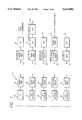
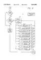
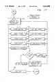
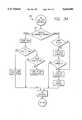
- FIGS. 3A, 3B and 3Cprovide an overview block diagram of the PC control program. After a program start 100 a program start up block 102 is executed. After comm checks are performed at block 104, stranded jobs are processed at block 106. Next, the PC control program proceeds to the display main menu block 108. Block 110 provides that the background comms are checked every second. As may be readily appreciated, other appropriate time intervals may be employed.
- the function keys of the keyboard 82are set up or programmed so that the operator can easily direct operation of the PC control program as desired. If function key F1 is selected, the PC control program proceeds to the show job queue block 112. If function key F2 is selected, a display stations block 114 is executed. If function key F3 is selected, a display fluids block 116 is executed. If function key F4 is selected, a display text block 118 is executed. If function key F5 is selected, a display operator's block 120 is executed. If function day F6 is selected, a close jobs block 122 is executed. If function key F7 is selected, a delete jobs block 124 is executed. If function F8 is selected, an add jobs block 126 is executed.
- the PC control programexecutes a menus block 128 providing the operator with a sub-menu of options. If the escape key is selected, a quit program block 130 initiates an exit from the PC control program 132 to the operating system of the PC 52.
- FIG. 4shows executable blocks 100, 102, 104 and 106 are shown in greater detail.
- FIG. 5shows in greater detail how the function keys are used to direct execution of the PC control program into various subroutines and that the operator is returned to the main menu after execution of the selected subroutine.
- a show job queue menuis presented to the PC operator with execution of the show job queue block 112.
- the PC control programis written to assign various program subroutines to different function keys as desired.
- other keys of the keyboard 82may be appropriately dedicated for use by the operator or that alternative user interfaces such as touch screens, cursors driven by movement of a mouse device, voice recognition systems, light sensitive devices or the like may be used by the PC operator to initiate execution of a desired program subroutine.
- a display job queue menu 134 shown in FIG. 6is executed.
- the following description of FIG. 6also describes the bottom half of FIG. 3B.
- the PC operatoris able to access information about fluid dispensing jobs by station, fluid type, technician and operator. Additionally, the operator may close, delete, add and modify jobs from this menu. If the tab key is selected at block 136, the operator is returned to the show job queue menu. If the function key F2 is selected, a display stations block 138 is executed. If the function key F3 is selected, a display fluids block 140 is executed. If the function key F4 is selected, a display technician block 142 is executed.
- a display operators block 144is executed. If the function key F6 is selected, a close job block 146 is executed. If the function key F7 is selected, a delete job block 148 is executed. If the function key F8 is selected, an add job block 150 is executed. If the function key F9 is selected, a modified job block 152 is executed. If the escape key is selected, a return to main menu block 154 is executed.
- FIG. 7shows a detailed block diagram of the PC control program display stations subroutine.
- a display station detail block 156 of the display stations subroutineallows the PC operator to obtain information about a selected station. Such information includes the identity of the technician working at the station, a description of jobs being performed at the station and of jobs waiting to be performed at the station, the nature of these jobs (i.e., what type of fluid is to be dispensed, the quantity to be dispensed, etc.), and the current prioritization of the pending jobs.
- FIG. 8shows a detailed block diagram of the PC control program display fluids subroutine.
- the PC operatoris provided with an interface whereby information about the various bulk fluids may be accessed.
- the PC 52maintains records of all fluid dispensations and uses these records to appropriately adjust baseline bulk fluid inventories.
- FIG. 9is a detailed block diagram of the PC control program display technicians subroutine.
- the PC operatorDuring execution of a display tech list block 160 of the display technicians subroutine, the PC operator is provided with information about the technicians and with a user interface for manipulating such information.
- the add tech selected block 162allows the PC operator to assign the selected technician to a particular work station.
- a delete tech selected block 164allows the PC operator to enter information into the system showing that a technician has finished his or her shift or has left the station for lunch, a coffee break or for some other reason.
- An edit tech selected block 166allows the PC operator to change the identity of a technician at a particular work station at a shift change.
- a print tech selected block 168prints or otherwise makes available data pertaining to the selected technician.
- block 168may be programmed to print information about all fluid dispensations performed by the selected technician during a particular day. Additionally or alternatively, block 168 may provide access to cumulative information pertaining to the selected technician such as a history of completed jobs, hours worked, etc.
- An escape selected block 170returns the PC operator to the main menu.
- FIG. 10shows a detailed block diagram of the PC control program display operator's subroutine.
- the PC operatoris able to view information about the various PC operators and to edit this information.
- the display operator's subroutineis substantially identical to the display technician's subroutine and, for the sake of brevity, will not be further discussed.
- FIG. 11is a detailed block diagram of the PC control program close jobs subroutine.
- a decisional diamond 174determines whether or not any jobs are qualified to close.
- a job which is qualified to closeis one which has been pumped to completion. If at least one job is completed, the close jobs subroutine proceeds to a more than one job to close diamond 176.
- a display eligible jobs block 178is executed if more than one job has been pumped to completion. If fewer than all of the jobs eligible to be closed are to be closed, a decisional diamond 180 directs further execution of the close jobs subroutine to a select job to close block 182. After a final decision by the operator is made to close a job at diamond 184, the operator enters his or her name and the job is closed at executable block 186.
- FIG. 12is a detailed block diagram of the PC control program delete jobs subroutine.
- a decisional diamond 188determines whether or not any jobs are qualified to be deleted.
- a job which is qualified to be deletedis a job which was never pumped.
- Subsequent executable blocks and decisional diamonds in FIG. 12are substantially identical to those of FIG. 11.
- FIG. 13is a detailed block diagram of the PC control program add jobs subroutine. After execution of a get job document number block 190, the program add jobs subroutine determines whether or not the PC operator has cancelled the job. If not, a get job information from user block 192 is executed thereby providing an interface through which the operator can enter information to add a job. If the entered job is not cancelled, an enter and send job block 194 is then executed.
- FIG. 14is a detailed block diagram of the PC control program modify job subroutine.
- a show menu: get operator selection block 195provides the PC operator with an interface whereby queued jobs may be modified. Through selection of appropriately dedicated keys, the operator can direct the PC control program to recycle a "no start” job which was authorized but not commenced before a time out condition occurred. Such "no start” jobs are stored in a memory device of the PC 52 and may be recycled through execution of a select job and recycle it block 196. When a job is to be released from the queue so that it may be started by the technician, the PC operator selects the appropriate key to execute a select job and release it block 197.
- the PC operatorselects an appropriate key to direct the program modify job subroutine toward execution of a select job and prioritize it block 198.
- the program modify job subroutineadditionally includes a select job and display information block 199.
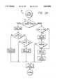
- FIG. 15is a detailed block diagram of the PC control program "menus" shown in the top half of FIG. 3C. The following description of FIG. 15 also describes the top half of FIG. 3C.
- the PC control programqueries the operator for a valid password at diamond 200. After a valid password is entered by the operator, a display menus block 202 is executed. From the "menus" display, the PC control program responds to selections by the operator of various keys from the keyboard 82. If the A key is selected, a job history report or summaries block 204 is executed. If the B key is selected, a fluid/station functions block 206 is executed. If the C key is selected, a lock buildings/remotes block 208 is executed.
- a backup/restore/reindex block 210is executed. If the H key is selected, a change configuration block 212 is executed. If the J key is selected, a change passwords block 214 is executed. If the K key is selected, a set date/time block 216 is executed. If the L or M keys are selected, a change screen display or change colors block 218 is executed. If the N or O keys are selected, a display version numbers block 220 is executed. If the escape key is selected, an exist block 222 is executed returning the operator to the main menu.
- FIG. 16is a detailed block diagram of the PC control program menu A subroutine.
- a display inventory/transaction menu block 224is executed.
- the menu A subroutineallows the PC operator to initiate, through the appropriate key selection, execution of a print report block 226. Reports generated from execution of block 226 include inventory and transaction reports.
- the PC operatormay also select an appropriate key to execute a print tech block 228 which allows a report pertinent to a selected technician to be printed.
- a file history data block 230provides a job history report or the like when executed.
- a fix history errors block 232is executed, the PC operator is presented with an opportunity to correct erroneous data discovered in displayed job histories. If the escape block 234 is executed, the PC operator is returned to the "menus" display.
- FIG. 17is a detailed block diagram of the PC control program menu B subroutine.
- a display station/fluid maintenance menu block 236is activated.
- the menu B subroutineprovides the PC operator with a user interface through which bulk fluid information may be accessed and modified as desired.
- the operatorinitiates execution of a change fluid data block 238 where, for example, a displayed quantity of fluid in a bulk fluid reservoir may be modified.
- Execution of a rename station block 240enables the operator to change the name of a station as it is recognized by the PCs 52.
- a rename fluid block 242similarly allows the PC operator to re-enter information stored in the PCs 52 and, more particularly, to rename a fluid associated with a particular bulk fluid reservoir 72. Such a software feature is desirable when a different type or grade of motor oil or when a different type of automotive fluid is to be dispensed from the bulk fluid reservoir 72.
- the appropriate keyis selected to initiate execution of a printer port block 244. Additionally, the PC operator may initiate execution of a rebuild fluid inventory block 246.
- the PC control programwill only rebuild the inventory when no jobs are open by reindexing all files and thereafter rebuilding inventory quantities from appropriately processed history files.
- the PC operatorinitiates execution of an escape block 248 to return to the "menus" display.
- FIG. 18is a detailed block diagram of the PC control program menu C subroutine.
- a display system lock/unlock menu block 250is executed.
- the menu C subroutinegenerally provides the PC operator with the ability to selectively lock or unlock single units or the entire system. Additionally, lock statuses may be displayed via the menu C subroutine.
- the remaining display options of the "menus" displayare discussed below.
- the PC operatorselects the E key, disk backup, restore, and reindex files become accessible and are preferably presented in a user friendly manner to the operator.
- Important informationsuch as transaction histories and fluid inventories can be archived as often as desired.
- the PC operatormay initiate a reindexing of stored filed.
- the PC control programmay alternatively be implemented to automatically backup transaction records and to reindex information on a desired periodic basis.
- a PC operatoris presented with yet another menu structure after successfully gaining access to the "menus" display.
- the PC operatoris prompted at diamond 252 as to whether or not access to a system menu is desired.
- access to the systems menumay additionally be made contingent upon entry of a valid password by the PC operator.
- FIG. 19is a detailed block diagram of the PC control program system menu shown in the bottom half of FIG. 3C. The following description of FIG. 19 also describes the bottom half of FIG. 3C.
- access to the system menuis determined at valid passwords diamond 254.
- the systems menuprovides access to and the ability to modify vital information such as fluid inventories modem configurations, etc.
- an additional level of securityis implemented by again asking the operator to provide a password.
- the password provided at diamond 254is different from the password provided at diamond 200.
- a display system menu block 256is executed. If the A key is selected, a modified fluid configuration block 258 is executed allowing the operator to add, modify or delete fluid data as desired.
- a modify station configuration block 260is executed allowing the operator to add, modify or delete station data. If the C key is selected, a print reports block 262 is executed providing printouts of work sheets and configuration data.
- the execution of blocks 258, 260 and 262may, but do not necessarily, provide access to and the ability to manipulate data beyond that which may be accessed or manipulated with other routines of the PC control program outside of the systems menu structure.
- Other keyboard activated routines accessible from the system menuprincipally pertain to testing and verifying communications between the PCs 52 and the remote controllers 56, adjusting communications timing, and establishing modem configurations.
- FIG. 20is a detailed block diagram of the PC program exit routine which is initiated by selecting the escape key from the main menu. Upon execution, the exit routine determines at diamond 264 whether or not a program forced exit exists. Such conditions include but are not limited to a fire alert condition, a theft alert condition, and a loss of power condition. Mechanisms for detecting these and other conditions and the provision of signals indicative of such conditions to computer interfaces are well known and therefore not illustrated in the figures accompanying this disclosure.
- the exit routinedetermines at diamond 266 whether or not any fluid dispensation jobs are still pending. If not, the exit routine turns off communications, clocks, closes data files, saves current statuses and quits the PC control program exiting to the operating system of the PC 52. If jobs are still pending, the operator is given an opportunity at diamond 268 to return to the main menu.
- FIG. 21is a detailed block diagram of the PC control program communications interrupt.
- the PC control programdetermines whether or not an incoming message from the remote controllers is present. After receiving such a message at receiving incoming messages block 272, the communications interrupt routine determines whether or not such messages are valid at diamond 274. If the job corresponding to the incoming message is to be processed, the update job status block 276 is executed. In either case, a send acknowledgement to remote block 278 is executed before the communications interrupt routine checks at diamond 280 to determine whether or not this is the last message to process.
- a job processing path of the communications interrupt routineis executed when there are no more valid incoming messages to be processed. First, a position at start of job file block 282 is executed. A process next job block 284, a last job in file diamond 286 and a communicate with remote if necessary block 288 are then sequentially executed until there are no more jobs in the file to be processed. At this point, a remove any deleted jobs and update job status block 290 is executed before the communications interrupt routine is exited.
- the remote controllers 56remotely communicate with the PCs 52 and are characterized by processing capability realized in software executed from the processors 60.
- PC serial portsprovide a remote communication link between the personal computers 52 and the remote controllers 56 and chain serial ports provide a communications interface, whether remote or otherwise, between different remote controllers 56.
- FIG. 22is a detailed block diagram of the remote controller start up procedure.
- the processor 60is set up at CPU set up block 292 and the building or site addresses are read at block 294.
- a system initialization block 296, an interrupt initialization block 298 and a serial port initialization block 300are then executed during the start up routine.
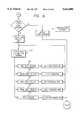
- FIG. 23is a block diagram of the remote controller scheduler. After initialization, the remote controllers 56 execute a poll subroutine 302 and a tasks subroutine 304 as shown in FIG. 23.
- the remote controller softwareis additionally programmed to respond to a PC port interrupt 306, a chain port interrupt 308 and a one second time tick 310.
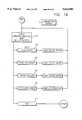
- FIG. 24is a detailed block diagram of the remote controller meter polling subroutine.
- the meter polling subroutinechecks all records which were addressed to and are now stored in memory of the remote controller 56. Further processing of queued jobs next proceeds to diamond 314 where the remote controller meter polling subroutine determines whether or not the first record calls for a real or test dispense.
- a perform selected test block 316executes diagnostic tests verifying the functionality of communications with the fluid flow meters 62 and the electric valves 64 and operation of the software controlled switching without actually pumping fluids.
- preprogrammed diagnosticsinclude a full dispense test, a partial dispense test and a never pump test.
- the meter polling subroutinechecks at diamond 318 to determine whether or not the status of the record is enabled. If yes, the meter polling subroutine then determines at diamond 320 whether or not a fluid dispensation is still in progress. The foregoing determination is made by checking to see whether a flow meter has clicked since it was last read. If yes, a mark record as pumping block 322 is executed. A flow meter click count is then incremented at block 324 before the meter polling subroutine checks at diamond 326 to determine whether or not the full authorized quantity has been pumped. If the entire authorized quantity has been dispensed, an end dispense block 328 is executed.
- a dispense time out diamond 330directs subsequent execution of the meter polling subroutine to the end dispense block 328 if the technician failed to dispense any of the bulk fluid for the duration of a predetermined dispense time out.
- the status of the recordis appropriately marked at block 332 depending upon whether or not the full authorized quantity was dispensed, a partial quantity was dispensed, or a no start condition occurred.
- a reset timer block 334resets the dispensed time out timer while fluids are actually being pumped thereby preventing a time out condition from occurring while a large volume of fluids is being dispensed.
- the meter polling subroutinedetermines at diamond 336 whether or not there are more records to check. If yes, then an appropriate pointer in the remote controller is directed toward the next record at block 338. If all queued records have been checked, the meter polling subroutine executes a poll fire alarm, set status block 340 and then returns to the scheduler routine.
- FIG. 25is a detailed block diagram of the remote controller subtask scheduler subroutine.
- the remote controller software"multiplexes" between the meter polling subroutine of FIG. 24 and a number of other subtasks as shown in FIG. 25.
- the subtask schedulerprocesses one of the following subroutines: process incoming PC messages; process outgoing PC messages; make a response message; process message to chain; process message from chain; do a background task; and start a new dispense.
- These subroutinesmay be executed sequentially in the order listed in the preceding sentence. Alternatively, other sequences may be provided depending upon the relative importance of the various subroutines with some of the subroutines being selected more frequently than others.
- FIG. 25is a detailed block diagram of the remote controller subtask scheduler subroutine.
- the remote controller software"multiplexes" between the meter polling subroutine of FIG. 24 and a number of other subtasks as shown in FIG. 25.
- the subtask schedulerprocesses one of
- the subtask schedulerincludes a process incoming PC message block 344, a process outgoing PC message block 346, a make a response message block 348, a process message to chain block 350, a process message from chain block 352, a do a background task block 354 and a start a new dispense block 356.
- the remote controller softwareexits from the subtask scheduler subroutine and returns to the meter polling subroutine.
- FIG. 26is a detailed block diagram of the remote controller PC-incoming message processing subroutine. If any message is received via the PC serial port needs to be processed, a decision diamond 358 directs the algorithm to a find oldest incoming message block 360. The "oldest incoming message" is the unprocessed message received earliest in time or a message which has been given priority to appear to be the oldest message. A message valid diamond 362 passes valid messages to a set flags from message block 364 where the remote controller software sets various software flags corresponding to particular bits of the processed message. Such flags indicate whether or not the message is to be passed at diamond 366 to another remote controller 56 further down the chain. If the message is addressed to a different remote controller 56, a queue chain out message block 368 is executed.
- a diamond 370directs the PC-incoming message processing subroutine to a queue and acknowledgement PC-out message block 372. Independent of whether or not the remote controller 56 needs to acknowledge the PC message, the PC-incoming message processing subroutine next executes a PC-command processing subroutine 374.
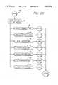
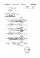
- FIG. 27is a detailed block diagram of the remote controller PC-command processing subroutine.
- a process by type of message block 376differentiates received messages by reading predesignated bit header information or the like.
- the remote controller 56responds to PC commands by modifying parameters stored within a memory device of the remote controller 56 or by transmitting information via the port to the PC 52.
- the PC-command processing subroutineexecutes a process cancel message block 378, a process status request block 380, a process new dispense message block 382, a process incoming acknowledgement message block 384, a process prioritize message block 386 or a process software version request block 388. After one of the foregoing blocks is executed, the remote controller software returns to the PC-incoming message processing subroutine.
- the PC-incoming message processing subroutineincludes a decrement incoming message count block 390 which is executed after a PC incoming message is processed and when the incoming message is for a different remote controller 56. After the incoming message count is decremented, the remote controller software returns to the meter polling subroutine.
- FIG. 28is a detailed block diagram of the remote controller PC-outgoing message processing subroutine. Messages are transmitted from ports to the PCs 52 when an affirmative determination is made at an outgoing message to process diamond 392. Another decisional diamond 394 returns the remote controller software to the meter polling subroutine if a message is presently being transmitted to the PCs 52. If no such transmission is occurring, a find an outgoing message to send now block 396 is executed. If a message is found, a send outgoing message block 398 and then a decrement message count block 400 are executed.
- FIG. 29is a detailed block diagram of the remote controller response message processing subroutine.
- a processor pointeris initially directed toward the memory location of a first record in a dispense list pursuant to execution block 402. As not all records require a response from the remote controllers 56, a record requires response diamond 404 directs execution to a process response by type block 406 only when a response is required. If no response is required, a point to next record in list block 408 is executed.
- the response message processing subroutineprocesses the messages by type and then executes a queue enabled message block 410, a queue pumping message block 412, a queue finished message block 414, a queue time out message block 416, or a resend old message not acknowledged block 418.
- a decisional diamond 420directs execution of the remote controller software back to the meter polling subroutine.
- FIG. 30is a detailed block diagram of the remote controller chain-incoming message processing subroutine.
- the remote controller software embodied in each processor 60facilitates bi-directional communication along a chain of serially or otherwise electronically interconnected remote controllers 56. After an affirmative determination is made at an incoming message to process decision diamond 422, a find incoming message block 424 is executed. Next, an adjust and queue outgoing message block 426 is executed.
- a storage device within the remote controllers 56stores queued incoming and outgoing messages from other remote controllers 56 and tracks how many such messages are queued at any given time. Accordingly, the chain-incoming message processing subroutine then executes an add to outgoing message count block 428 and then a decrement incoming message count block 430.
- FIG. 31is a detailed block diagram of the remote controller chain-outgoing message processing subroutine.
- a decisional diamond 432first determines whether or not an outgoing message to another remote controller 56 needs to be processed. If yes, a message sending now diamond 434 checks to see if a message is presently being transmitted via the PC serial port. If no, a find an outgoing message to send now block 436 is executed. If a message is found, a send an outgoing message block 438 and then a decrement message count block 440 are executed.
- FIG. 32is a detailed block diagram of the remote controller background tasks subroutine. After execution of a select one task each time through block 442, the background tasks subroutine performs at least one task from a group including but not limited to a count dispense records block 444, a write interrupt table block 446, a verified PC out message count block 448, a verified chain-out message count block 450, a verified PC-in message count block 452 and a verified chain-in message count block 454.
- An ordering of and a determination of how frequently the foregoing tasks will be selectedmay be adjusted to depend upon the relative importance of each task at any given time during execution of the remote controller software.
- FIG. 33is a detailed block diagram of the remote controller new job start subroutine.
- the remote controller softwareallows the PC operator to send a job to a specified fluid flow meter 62.
- An affirmative determination at a start job with a specified meter diamond 456directs execution of the remote controller software to another diamond 458 where the new job start subroutine determines whether or not the selected meter is available for use. If the meter is not in use, a diamond 460 directs execution of the remote controller software to an enable this pumping job block 462 only if the job is a real job rather than a test job. In either case, a mark record as enabled block 464 is executed thereafter.
- the PC operatormay alternatively wish to send the job to any available fluid station which is dispensing the desired bulk fluid from one of its meters 62.
- diamond 456directs execution of the remote controller software to a find an unstarted job block 466.
- the new job start subroutinethen checks at diamond 468 whether or not any request conflicts exist. If no conflict is present, the remote controller software advances to the diamond 458 and continues execution as discussed above. If a start up cannot be initiated without a conflict, the remote controller software returns to the meter polling subroutine.
- FIG. 34is a detailed block diagram of the remote controller serial interrupt from PC port.
- the serial interrupt from PC port routinedetermines whether or not a message is to be received or transmitted during interrupt processing.
- the respective processing paths of the receive and transmit interruptsare carried out as shown in FIG. 34 and are self explanatory.
- FIG. 35is a detailed block diagram of the remote controller serial interrupt from chain port.
- a decisional diamond 472determines whether or not the chain serial port interrupt requires processing for a receive or transmit signal.
- FIG. 36is a detailed block diagram of the remote controller one second time tick interrupt.
- a decisional diamond 474provides an input to a watch dog timer block 476 which in turn initiates the toggling of a light emitting diode or similar device at block 478.
- the remote controllers 56may additionally include a user interface enabling the technicians to request authorization for a fluid dispensation.
- the PCs 52may be programmed to automatically update inventories and other stored information. Communication links between the PCs 52 and the remote controllers 56 are not necessarily limited to those including serial port interfaces as other more advanced transmission techniques are contemplated as being within the scope of the present invention.
- a full keyboard, monitor and computeras shown at the upper left in FIG.
Landscapes
- Engineering & Computer Science (AREA)
- Mechanical Engineering (AREA)
- Physics & Mathematics (AREA)
- Mathematical Physics (AREA)
- Theoretical Computer Science (AREA)
- Computer Networks & Wireless Communication (AREA)
- Selective Calling Equipment (AREA)
- Loading And Unloading Of Fuel Tanks Or Ships (AREA)
Abstract
Description
Claims (23)
Priority Applications (4)
| Application Number | Priority Date | Filing Date | Title |
|---|---|---|---|
| US08/445,053US5612890A (en) | 1995-05-19 | 1995-05-19 | System and method for controlling product dispensation utilizing metered valve apparatus and electronic interconnection map corresponding to plumbing interconnections |
| PCT/US1996/007046WO1996036924A1 (en) | 1995-05-19 | 1996-05-16 | Remote control dispensing system |
| CA002221362ACA2221362C (en) | 1995-05-19 | 1996-05-16 | Remote control dispensing system |
| AU57517/96AAU5751796A (en) | 1995-05-19 | 1996-05-16 | Remote control dispensing system |
Applications Claiming Priority (1)
| Application Number | Priority Date | Filing Date | Title |
|---|---|---|---|
| US08/445,053US5612890A (en) | 1995-05-19 | 1995-05-19 | System and method for controlling product dispensation utilizing metered valve apparatus and electronic interconnection map corresponding to plumbing interconnections |
Publications (1)
| Publication Number | Publication Date |
|---|---|
| US5612890Atrue US5612890A (en) | 1997-03-18 |
Family
ID=23767430
Family Applications (1)
| Application Number | Title | Priority Date | Filing Date |
|---|---|---|---|
| US08/445,053Expired - Fee RelatedUS5612890A (en) | 1995-05-19 | 1995-05-19 | System and method for controlling product dispensation utilizing metered valve apparatus and electronic interconnection map corresponding to plumbing interconnections |
Country Status (4)
| Country | Link |
|---|---|
| US (1) | US5612890A (en) |
| AU (1) | AU5751796A (en) |
| CA (1) | CA2221362C (en) |
| WO (1) | WO1996036924A1 (en) |
Cited By (53)
| Publication number | Priority date | Publication date | Assignee | Title |
|---|---|---|---|---|
| US5969691A (en)* | 1998-02-10 | 1999-10-19 | Gilbarco Inc. | Fuel dispenser transponder antenna arrangement |
| FR2787417A1 (en)* | 1998-12-22 | 2000-06-23 | Tokheim Corp | Remote controlled automated fuel dispensing system in service station, uses robotic actuator for refueling based on positioned relationship of fuel inlet actuator and nozzle determined by vision system |
| WO2000042522A1 (en)* | 1999-01-14 | 2000-07-20 | Rawls & Winstead, Inc. | Method and apparatus for site management |
| US6101427A (en)* | 1998-02-02 | 2000-08-08 | Yang; Yun Jong | Automatic lubricating oil feeding system capable of centralized control via radio link |
| WO2000064745A1 (en)* | 1999-04-22 | 2000-11-02 | Tokheim Corporation | Method of providing automated remote control of the operation of multiple refueling stations |
| US6360141B1 (en)* | 1997-05-26 | 2002-03-19 | Metax-Olie A/S | System for establishing automatic access to fuel upright and method for filling up of a vehicle |
| US20020152123A1 (en)* | 1999-02-19 | 2002-10-17 | Exxonmobil Research And Engineering Company | System and method for processing financial transactions |
| US6470288B1 (en) | 1999-06-18 | 2002-10-22 | Tokheim Corporation | Dispenser with updatable diagnostic system |
| EP1208690A4 (en)* | 1999-08-06 | 2003-01-15 | Tokheim Corp | Telephonic energy or fuel dispenser activation and payment system |
| US20030043052A1 (en)* | 1994-10-24 | 2003-03-06 | Fisher-Rosemount Systems, Inc. | Apparatus for providing redundant wireless access to field devices in a distributed control system |
| US6625519B2 (en) | 2001-10-01 | 2003-09-23 | Veeder-Root Company Inc. | Pump controller for submersible turbine pumps |
| US6659306B2 (en) | 2001-10-02 | 2003-12-09 | Badger Meter, Inc. | Electronic lube gun with master station control |
| US20040004555A1 (en)* | 2002-07-03 | 2004-01-08 | Schlumbergersema Inc. | Field selectable communication network |
| US6704617B2 (en) | 2002-04-11 | 2004-03-09 | Flexible Products Company | Automated system for control and diagnostics for dispensing systems |
| US6760792B1 (en)* | 2001-10-15 | 2004-07-06 | Advanced Micro Devices, Inc. | Buffer circuit for rotating outstanding transactions |
| US20040140327A1 (en)* | 2003-01-02 | 2004-07-22 | Osborne Michael D. | Pressurized fluid dispenser |
| US6823270B1 (en)* | 2001-06-20 | 2004-11-23 | Curtis Roys | Fluid flow monitoring system |
| US6850849B1 (en)* | 2001-06-20 | 2005-02-01 | Curtis Roys | Fluid flow monitor and control system |
| US20050096785A1 (en)* | 2003-11-03 | 2005-05-05 | Moncrief James W. | System and software of enhanced pharmaceutical operations in long-term care facilities and related methods |
| US20050225441A1 (en)* | 2004-04-06 | 2005-10-13 | Kernan Timothy S | System and method for monitoring management |
| US20060032533A1 (en)* | 2002-07-08 | 2006-02-16 | Fisher-Rosemount Systems, Inc. | System and method for automating or metering fluid recovered at a well |
| US20060047360A1 (en)* | 2004-08-24 | 2006-03-02 | Burns Patrick J Sr | Control system and method for chemical injection |
| US20060168085A1 (en)* | 1995-06-05 | 2006-07-27 | Tetsuro Motoyama | Method and system for diagnosis and control of machines using connection and connectionless modes of communication |
| US20070068393A1 (en)* | 2005-04-11 | 2007-03-29 | Coffee Equipment Company | Machine for brewing a beverage such as coffee and related method |
| US20090095165A1 (en)* | 2005-04-11 | 2009-04-16 | Coffee Equipment Company | Machine for brewing a beverage such as coffee and related method |
| US20090112364A1 (en)* | 2007-10-31 | 2009-04-30 | Honeywell International Inc. | Chemical treatment system and method |
| US20090107921A1 (en)* | 2007-10-26 | 2009-04-30 | Honeywell International Inc. | Chemical treatment system and method |
| US7571139B1 (en) | 1999-02-19 | 2009-08-04 | Giordano Joseph A | System and method for processing financial transactions |
| US7640185B1 (en) | 1995-12-29 | 2009-12-29 | Dresser, Inc. | Dispensing system and method with radio frequency customer identification |
| US20130277148A1 (en)* | 2012-04-20 | 2013-10-24 | Aktiebolaget Skf | Lubrication system and controller |
| US9298176B2 (en) | 2012-01-17 | 2016-03-29 | Fisher-Rosemount Systems, Inc. | Compensating for setpoint changes in a non-periodically updated controller |
| US9506785B2 (en) | 2013-03-15 | 2016-11-29 | Rain Bird Corporation | Remote flow rate measuring |
| US20180265344A1 (en)* | 2013-03-13 | 2018-09-20 | Berg Company, Llc | Wireless Control System for Dispensing Beverages from a Bottle |
| US10423127B2 (en) | 2012-01-17 | 2019-09-24 | Fisher-Rosemount Systems, Inc. | Velocity based control in a non-periodically updated controller |
| US10473494B2 (en) | 2017-10-24 | 2019-11-12 | Rain Bird Corporation | Flow sensor |
| US10634538B2 (en) | 2016-07-13 | 2020-04-28 | Rain Bird Corporation | Flow sensor |
| US10796500B2 (en)* | 2017-08-01 | 2020-10-06 | Ford Global Technologies, Llc | Electronic communication modules provisioning for smart connectivity |
| US11108865B1 (en) | 2020-07-27 | 2021-08-31 | Zurn Industries, Llc | Battery powered end point device for IoT applications |
| US11153945B1 (en) | 2020-12-14 | 2021-10-19 | Zurn Industries, Llc | Facility occupancy detection with thermal grid sensor |
| US11199824B2 (en) | 2012-01-17 | 2021-12-14 | Fisher-Rosemount Systems, Inc. | Reducing controller updates in a control loop |
| US11221601B1 (en) | 2021-05-24 | 2022-01-11 | Zurn Industries, Llc | Various IoT sensory products and cloud-purge for commercial building solutions utilizing LoRa to BACnet conversion for efficient data management and monitoring |
| US11316908B1 (en) | 2021-02-01 | 2022-04-26 | Zurn Industries, Llc | BACnet conversion of water management data for building management solutions |
| US11488457B2 (en) | 2020-06-08 | 2022-11-01 | Zurn Industries, Llc | Cloud-connected occupancy lights and status indication |
| US11514679B1 (en) | 2022-02-18 | 2022-11-29 | Zurn Industries, Llc | Smart method for noise rejection in spatial human detection systems for a cloud connected occupancy sensing network |
| US11543791B1 (en) | 2022-02-10 | 2023-01-03 | Zurn Industries, Llc | Determining operations for a smart fixture based on an area status |
| US11555734B1 (en) | 2022-02-18 | 2023-01-17 | Zurn Industries, Llc | Smart and cloud connected detection mechanism and real-time internet of things (IoT) system management |
| US11594119B2 (en) | 2021-05-21 | 2023-02-28 | Zurn Industries, Llc | System and method for providing a connection status of a battery powered end point device |
| US11662242B2 (en) | 2018-12-31 | 2023-05-30 | Rain Bird Corporation | Flow sensor gauge |
| US11803166B2 (en) | 2021-09-03 | 2023-10-31 | Zurn Industries, Llc | Systems and methods for determining operations of a smart fixture |
| US20240295167A1 (en)* | 2023-03-03 | 2024-09-05 | Halliburton Energy Services, Inc. | Packing lubrication system for multiple pumping units |
| US12269729B2 (en) | 2023-01-27 | 2025-04-08 | Vgp Ipco Llc | Reusable or refillable container for dispensing motor oil |
| US12301661B2 (en) | 2019-12-06 | 2025-05-13 | Zurn Water, Llc | Water management system and user interface |
| US12443208B2 (en) | 2023-02-08 | 2025-10-14 | Rain Bird Corporation | Control zone devices, systems and methods |
Citations (26)
| Publication number | Priority date | Publication date | Assignee | Title |
|---|---|---|---|---|
| US3541513A (en)* | 1967-09-01 | 1970-11-17 | Gen Electric | Communications control apparatus for sequencing digital data and analog data from remote stations to a central data processor |
| US3927800A (en)* | 1973-09-20 | 1975-12-23 | Dresser Ind | Control and data system |
| US4127845A (en)* | 1975-01-10 | 1978-11-28 | General Signal Corporation | Communications system |
| US4135181A (en)* | 1976-01-30 | 1979-01-16 | General Electric Company | Automatic remote meter reading and control system |
| US4161720A (en)* | 1977-05-23 | 1979-07-17 | General Electric Company | Meter terminal unit for use in automatic remote meter reading and control system |
| US4204195A (en)* | 1977-05-23 | 1980-05-20 | General Electric Company | Meter terminal unit for use in automatic remote meter reading and control system |
| US4608560A (en)* | 1981-06-09 | 1986-08-26 | Adec, Inc. | Computer controlled energy monitoring system |
| US4636950A (en)* | 1982-09-30 | 1987-01-13 | Caswell Robert L | Inventory management system using transponders associated with specific products |
| US4644547A (en)* | 1984-06-28 | 1987-02-17 | Westinghouse Electric Corp. | Digital message format for two-way communication and control network |
| US4855729A (en)* | 1986-02-10 | 1989-08-08 | Tokyo Keiki Company Ltd. | Communication control system of fluid control valve |
| US4879756A (en)* | 1986-09-22 | 1989-11-07 | Stevens John K | Radio broadcast communication systems |
| US4910658A (en)* | 1985-09-04 | 1990-03-20 | Eaton Leonard Technologies, Inc. | Real time process controller with serial I/O bus |
| US4930665A (en)* | 1988-09-19 | 1990-06-05 | Gilbarco Inc. | Liquid dispensing system with electronically controlled valve remote from nozzle |
| US4934565A (en)* | 1988-09-19 | 1990-06-19 | Gilbarco Inc. | Liquid dispensing system with electronically controlled valve remote from nozzle |
| US5054995A (en)* | 1989-11-06 | 1991-10-08 | Ingersoll-Rand Company | Apparatus for controlling a fluid compression system |
| US5056017A (en)* | 1989-07-31 | 1991-10-08 | Lrs, Inc. | System to monitor fuel level in a tank, and fuel dispensed from the tank, to determine fuel leakage and theft losses |
| US5058044A (en)* | 1989-03-30 | 1991-10-15 | Auto I.D. Inc. | Automated maintenance checking system |
| US5077671A (en)* | 1989-07-05 | 1991-12-31 | The Boeing Company | Test cart for aircraft control surface measurements |
| US5122948A (en)* | 1990-06-28 | 1992-06-16 | Allen-Bradley Company, Inc. | Remote terminal industrial control communication system |
| US5249129A (en)* | 1991-02-22 | 1993-09-28 | Alain Lamoureux | Method and system for dispensing precise amount of fluid with automatic set reset |
| US5252967A (en)* | 1990-05-25 | 1993-10-12 | Schlumberger Industries, Inc. | Reader/programmer for two and three wire utility data communications system |
| US5270943A (en)* | 1992-01-03 | 1993-12-14 | Progressive International Electronics | Fuel pump control card |
| US5270701A (en)* | 1988-03-08 | 1993-12-14 | Kokusai Denshin Denwa Co., Ltd. | Service processing system with distributed data bases |
| US5361216A (en)* | 1992-07-02 | 1994-11-01 | Progressive International Electronics | Flow signal monitor for a fuel dispensing system |
| US5394336A (en)* | 1993-12-22 | 1995-02-28 | Progressive International Electronics | Fuel dispenser-cash register control console |
| US5400253A (en)* | 1993-11-26 | 1995-03-21 | Southern Power, Inc. | Automated statistical inventory reconcilation system for convenience stores and auto/truck service stations |
Family Cites Families (4)
| Publication number | Priority date | Publication date | Assignee | Title |
|---|---|---|---|---|
| CA1085513A (en)* | 1975-10-03 | 1980-09-09 | Allen F. Pearson | Dispensing system |
| US5225995A (en)* | 1985-01-25 | 1993-07-06 | Sharp Kabushiki Kaisha | Flow rate measurement control for refuelling control system |
| US5029100A (en)* | 1989-12-15 | 1991-07-02 | Gilbarco Inc. | Blender system for fuel dispenser |
| CA2056099A1 (en)* | 1990-12-07 | 1992-06-08 | Gregory S. Lieto | Direct interface between fuel pump and computer/cash register |
- 1995
- 1995-05-19USUS08/445,053patent/US5612890A/ennot_activeExpired - Fee Related
- 1996
- 1996-05-16CACA002221362Apatent/CA2221362C/ennot_activeExpired - Fee Related
- 1996-05-16AUAU57517/96Apatent/AU5751796A/ennot_activeAbandoned
- 1996-05-16WOPCT/US1996/007046patent/WO1996036924A1/enactiveSearch and Examination
Patent Citations (26)
| Publication number | Priority date | Publication date | Assignee | Title |
|---|---|---|---|---|
| US3541513A (en)* | 1967-09-01 | 1970-11-17 | Gen Electric | Communications control apparatus for sequencing digital data and analog data from remote stations to a central data processor |
| US3927800A (en)* | 1973-09-20 | 1975-12-23 | Dresser Ind | Control and data system |
| US4127845A (en)* | 1975-01-10 | 1978-11-28 | General Signal Corporation | Communications system |
| US4135181A (en)* | 1976-01-30 | 1979-01-16 | General Electric Company | Automatic remote meter reading and control system |
| US4161720A (en)* | 1977-05-23 | 1979-07-17 | General Electric Company | Meter terminal unit for use in automatic remote meter reading and control system |
| US4204195A (en)* | 1977-05-23 | 1980-05-20 | General Electric Company | Meter terminal unit for use in automatic remote meter reading and control system |
| US4608560A (en)* | 1981-06-09 | 1986-08-26 | Adec, Inc. | Computer controlled energy monitoring system |
| US4636950A (en)* | 1982-09-30 | 1987-01-13 | Caswell Robert L | Inventory management system using transponders associated with specific products |
| US4644547A (en)* | 1984-06-28 | 1987-02-17 | Westinghouse Electric Corp. | Digital message format for two-way communication and control network |
| US4910658A (en)* | 1985-09-04 | 1990-03-20 | Eaton Leonard Technologies, Inc. | Real time process controller with serial I/O bus |
| US4855729A (en)* | 1986-02-10 | 1989-08-08 | Tokyo Keiki Company Ltd. | Communication control system of fluid control valve |
| US4879756A (en)* | 1986-09-22 | 1989-11-07 | Stevens John K | Radio broadcast communication systems |
| US5270701A (en)* | 1988-03-08 | 1993-12-14 | Kokusai Denshin Denwa Co., Ltd. | Service processing system with distributed data bases |
| US4930665A (en)* | 1988-09-19 | 1990-06-05 | Gilbarco Inc. | Liquid dispensing system with electronically controlled valve remote from nozzle |
| US4934565A (en)* | 1988-09-19 | 1990-06-19 | Gilbarco Inc. | Liquid dispensing system with electronically controlled valve remote from nozzle |
| US5058044A (en)* | 1989-03-30 | 1991-10-15 | Auto I.D. Inc. | Automated maintenance checking system |
| US5077671A (en)* | 1989-07-05 | 1991-12-31 | The Boeing Company | Test cart for aircraft control surface measurements |
| US5056017A (en)* | 1989-07-31 | 1991-10-08 | Lrs, Inc. | System to monitor fuel level in a tank, and fuel dispensed from the tank, to determine fuel leakage and theft losses |
| US5054995A (en)* | 1989-11-06 | 1991-10-08 | Ingersoll-Rand Company | Apparatus for controlling a fluid compression system |
| US5252967A (en)* | 1990-05-25 | 1993-10-12 | Schlumberger Industries, Inc. | Reader/programmer for two and three wire utility data communications system |
| US5122948A (en)* | 1990-06-28 | 1992-06-16 | Allen-Bradley Company, Inc. | Remote terminal industrial control communication system |
| US5249129A (en)* | 1991-02-22 | 1993-09-28 | Alain Lamoureux | Method and system for dispensing precise amount of fluid with automatic set reset |
| US5270943A (en)* | 1992-01-03 | 1993-12-14 | Progressive International Electronics | Fuel pump control card |
| US5361216A (en)* | 1992-07-02 | 1994-11-01 | Progressive International Electronics | Flow signal monitor for a fuel dispensing system |
| US5400253A (en)* | 1993-11-26 | 1995-03-21 | Southern Power, Inc. | Automated statistical inventory reconcilation system for convenience stores and auto/truck service stations |
| US5394336A (en)* | 1993-12-22 | 1995-02-28 | Progressive International Electronics | Fuel dispenser-cash register control console |
Non-Patent Citations (2)
| Title |
|---|
| Vehicle Lubrication Systems - 114 Catalog, Graco Inc. Form No. 303-040, Rev. Feb. 1992, pp. 8-9, 48-50. |
| Vehicle Lubrication Systems 114 Catalog, Graco Inc. Form No. 303 040, Rev. Feb. 1992, pp. 8 9, 48 50.* |
Cited By (116)
| Publication number | Priority date | Publication date | Assignee | Title |
|---|---|---|---|---|
| US20050047330A1 (en)* | 1994-10-24 | 2005-03-03 | Fisher-Rosemount System, Inc. | Wireless transceiver pair disposed within a process control system |
| US7623479B2 (en) | 1994-10-24 | 2009-11-24 | Fisher-Rosemount Systems, Inc. | Process control system devices with dual hardwired and wireless communication ports |
| US8184562B2 (en) | 1994-10-24 | 2012-05-22 | Fisher-Rosemount Systems, Inc. | Process control system having dual wireless communication links |
| US20050076151A1 (en)* | 1994-10-24 | 2005-04-07 | Fisher-Rosemount Systems, Inc. | Wireless bridge device within a process control system |
| US20050047331A1 (en)* | 1994-10-24 | 2005-03-03 | Fisher-Rosemount Systems, Inc. | Process control system devices with dual hardwired and wireless communication ports |
| US20050049727A1 (en)* | 1994-10-24 | 2005-03-03 | Fisher-Rosemount Systems, Inc. | Wireless communications within a process control system using a bus protocol |
| US7453834B2 (en) | 1994-10-24 | 2008-11-18 | Fisher-Rosemount Systems, Inc. | Distributed control system for controlling material flow having wireless transceiver connected to industrial process control field device to provide redundant wireless access |
| US7602741B2 (en) | 1994-10-24 | 2009-10-13 | Fisher-Rosemount Systems, Inc. | Field device in a process control system using wireless radio communications to transmit and receive sense and control signals |
| US7609660B2 (en) | 1994-10-24 | 2009-10-27 | Fisher-Rosemount Systems, Inc. | Wireless transceiver pair disposed within a process control system |
| US20100074156A1 (en)* | 1994-10-24 | 2010-03-25 | Fisher-Rosemount Systems, Inc. | Process Control System Using Wireless Communication Links |
| US7519012B2 (en)* | 1994-10-24 | 2009-04-14 | Fisher-Rosemount Systems, Inc. | Distributed control system for controlling material flow having wireless transceiver connected to industrial process control field device to provide redundant wireless access |
| US20030043052A1 (en)* | 1994-10-24 | 2003-03-06 | Fisher-Rosemount Systems, Inc. | Apparatus for providing redundant wireless access to field devices in a distributed control system |
| US7447809B2 (en)* | 1995-06-05 | 2008-11-04 | Ricoh Company, Ltd. | System using internet application for monitoring metering device and sharing metering information among departments |
| US20060168085A1 (en)* | 1995-06-05 | 2006-07-27 | Tetsuro Motoyama | Method and system for diagnosis and control of machines using connection and connectionless modes of communication |
| US7640185B1 (en) | 1995-12-29 | 2009-12-29 | Dresser, Inc. | Dispensing system and method with radio frequency customer identification |
| US6360141B1 (en)* | 1997-05-26 | 2002-03-19 | Metax-Olie A/S | System for establishing automatic access to fuel upright and method for filling up of a vehicle |
| US6101427A (en)* | 1998-02-02 | 2000-08-08 | Yang; Yun Jong | Automatic lubricating oil feeding system capable of centralized control via radio link |
| US5969691A (en)* | 1998-02-10 | 1999-10-19 | Gilbarco Inc. | Fuel dispenser transponder antenna arrangement |
| US6367516B1 (en)* | 1998-12-22 | 2002-04-09 | Tokheim Corporation | Method of providing automated remote control of the operation of multiple refueling stations |
| WO2000037355A1 (en)* | 1998-12-22 | 2000-06-29 | Tokheim Corporation | Automated fueling system with remote service facility to operate multiple refuelling stations |
| FR2787417A1 (en)* | 1998-12-22 | 2000-06-23 | Tokheim Corp | Remote controlled automated fuel dispensing system in service station, uses robotic actuator for refueling based on positioned relationship of fuel inlet actuator and nozzle determined by vision system |
| US6390151B1 (en)* | 1998-12-22 | 2002-05-21 | Tokheim Corporation | Automated fueling system with remote service facility to operate multiple refueling stations |
| WO2000042522A1 (en)* | 1999-01-14 | 2000-07-20 | Rawls & Winstead, Inc. | Method and apparatus for site management |
| US6259956B1 (en)* | 1999-01-14 | 2001-07-10 | Rawl & Winstead, Inc. | Method and apparatus for site management |
| US7571139B1 (en) | 1999-02-19 | 2009-08-04 | Giordano Joseph A | System and method for processing financial transactions |
| US8538801B2 (en) | 1999-02-19 | 2013-09-17 | Exxonmobile Research & Engineering Company | System and method for processing financial transactions |
| US20020152123A1 (en)* | 1999-02-19 | 2002-10-17 | Exxonmobil Research And Engineering Company | System and method for processing financial transactions |
| WO2000064745A1 (en)* | 1999-04-22 | 2000-11-02 | Tokheim Corporation | Method of providing automated remote control of the operation of multiple refueling stations |
| EP1178926A4 (en)* | 1999-04-22 | 2004-03-17 | Tokheim Corp | Method of providing automated remote control of the operation of multiple refueling stations |
| FR2792925A1 (en)* | 1999-04-22 | 2000-11-03 | Tokheim Corp | METHOD FOR CREATING A REMOTE CONTROL OF THE OPERATION OF MULTIPLE FUEL SUPPLY STATIONS |
| US6470288B1 (en) | 1999-06-18 | 2002-10-22 | Tokheim Corporation | Dispenser with updatable diagnostic system |
| EP1208690A4 (en)* | 1999-08-06 | 2003-01-15 | Tokheim Corp | Telephonic energy or fuel dispenser activation and payment system |
| US6823270B1 (en)* | 2001-06-20 | 2004-11-23 | Curtis Roys | Fluid flow monitoring system |
| US20110231114A1 (en)* | 2001-06-20 | 2011-09-22 | Curtis Roys | Fluid flow monitor and control system |
| US7970558B1 (en) | 2001-06-20 | 2011-06-28 | Coltec Industrial Products Llc | Fluid flow monitor and control system |
| US7720574B1 (en)* | 2001-06-20 | 2010-05-18 | Curtis Roys | Fluid flow monitor and control system |
| US7379827B1 (en) | 2001-06-20 | 2008-05-27 | Curtis Roys | Fluid flow monitoring system |
| US8561477B2 (en) | 2001-06-20 | 2013-10-22 | Coltec Industrial Products Llc | Fluid flow monitor and control system |
| US6850849B1 (en)* | 2001-06-20 | 2005-02-01 | Curtis Roys | Fluid flow monitor and control system |
| US6625519B2 (en) | 2001-10-01 | 2003-09-23 | Veeder-Root Company Inc. | Pump controller for submersible turbine pumps |
| US6659306B2 (en) | 2001-10-02 | 2003-12-09 | Badger Meter, Inc. | Electronic lube gun with master station control |
| US6760792B1 (en)* | 2001-10-15 | 2004-07-06 | Advanced Micro Devices, Inc. | Buffer circuit for rotating outstanding transactions |
| US6704617B2 (en) | 2002-04-11 | 2004-03-09 | Flexible Products Company | Automated system for control and diagnostics for dispensing systems |
| US20040004555A1 (en)* | 2002-07-03 | 2004-01-08 | Schlumbergersema Inc. | Field selectable communication network |
| US20060032533A1 (en)* | 2002-07-08 | 2006-02-16 | Fisher-Rosemount Systems, Inc. | System and method for automating or metering fluid recovered at a well |
| US7878250B2 (en) | 2002-07-08 | 2011-02-01 | Fisher-Rosemount Systems, Inc. | System and method for automating or metering fluid recovered at a well |
| US20040140327A1 (en)* | 2003-01-02 | 2004-07-22 | Osborne Michael D. | Pressurized fluid dispenser |
| US20100198615A1 (en)* | 2003-11-03 | 2010-08-05 | Tech Pharmacy Services, Inc. | System and Software of Enhanced Pharmaceutical Operations in Long-Term Care Facilities and Related Methods |
| US9740830B2 (en) | 2003-11-03 | 2017-08-22 | Tech Pharmacy Services, Llc | Method of enhanced distribution of pharmaceuticals in long-term care facilities |
| US11348054B2 (en) | 2003-11-03 | 2022-05-31 | Tech Pharmacy Services, Llc | System and method of enhanced distribution of pharmaceuticals in long-term care facilities |
| US11341450B2 (en) | 2003-11-03 | 2022-05-24 | Tech Pharmacy Services, Llc | Method of enhanced distribution of pharmaceuticals in long-term care facilities |
| US9747422B2 (en) | 2003-11-03 | 2017-08-29 | Tech Pharmacy Services, Llc | System and method of enhanced distribution of pharmaceuticals in long-term care facilities |
| US9710609B2 (en) | 2003-11-03 | 2017-07-18 | Tech Pharmacy Services, Llc | System of enhanced distribution of pharmaceuticals in long-term care facilities |
| US7685004B2 (en) | 2003-11-03 | 2010-03-23 | Tech Pharmacy Services, Inc. | System and software of enhanced pharmaceutical operations in long-term care facilities and related methods |
| US8954338B2 (en) | 2003-11-03 | 2015-02-10 | Tech Pharmacy Services, Inc. | System and method of enhanced distribution of pharmaceuticals in long-term care facilities |
| US7698019B2 (en)* | 2003-11-03 | 2010-04-13 | Tech Pharmacy Services, Inc. | System and software of enhanced pharmaceutical operations in long-term care facilities and related methods |
| US20080091467A1 (en)* | 2003-11-03 | 2008-04-17 | Tech Pharmacy Services, Inc. | System and Software of Enhanced Pharmaceutical Operations in Long-Term Care Facilities and Related Methods |
| US8612256B1 (en) | 2003-11-03 | 2013-12-17 | Tech Pharmacy Services, Inc. | System and software of enhanced pharmaceutical operations in long-term care facilities and related methods |
| US20070250210A1 (en)* | 2003-11-03 | 2007-10-25 | Tech Pharmacy Services, Inc. | System and software of enhanced pharmaceutical operations in long-term care facilities and related methods |
| US20050096785A1 (en)* | 2003-11-03 | 2005-05-05 | Moncrief James W. | System and software of enhanced pharmaceutical operations in long-term care facilities and related methods |
| US8554574B2 (en) | 2003-11-03 | 2013-10-08 | Tech Pharmacy Services, Inc. | System and software of enhanced pharmaceutical operations in long-term care facilities and related methods |
| US8489425B2 (en) | 2003-11-03 | 2013-07-16 | Tech Pharmacy Services, Inc. | System and software of enhanced pharmaceutical operations in long-term care facilities and related methods |
| USRE44127E1 (en) | 2003-11-03 | 2013-04-02 | Tech Pharmacy Services, Inc. | System and software of enhanced pharmaceutical operations in long-term care facilities and related methods |
| US8260632B2 (en) | 2003-11-03 | 2012-09-04 | Tech Pharmacy Services, Inc. | System and software of enhanced pharmaceutical operations in long-term care facilities and related methods |
| US8204761B2 (en) | 2003-11-03 | 2012-06-19 | Tech Pharmacy Services, Inc. | System and software of enhanced pharmaceutical operations in long-term care facilities and related methods |
| US8209193B2 (en) | 2003-11-03 | 2012-06-26 | Tech Pharmacy Services, Inc. | System and software of enhanced pharmaceutical operations in long-term care facilities and related methods |
| US7457869B2 (en) | 2004-04-06 | 2008-11-25 | Sitewatch Technologies, Llc | System and method for monitoring management |
| US20050225441A1 (en)* | 2004-04-06 | 2005-10-13 | Kernan Timothy S | System and method for monitoring management |
| US7277778B2 (en)* | 2004-08-24 | 2007-10-02 | Burns Control Company | Control system and method for chemical injection |
| US20060047360A1 (en)* | 2004-08-24 | 2006-03-02 | Burns Patrick J Sr | Control system and method for chemical injection |
| WO2006022891A3 (en)* | 2004-08-24 | 2007-08-23 | Burns Control Company | Control system and method for chemical injection |
| US7673555B2 (en) | 2005-04-11 | 2010-03-09 | Starbucks Corporation | Machine for brewing a beverage such as coffee and related method |
| US20100024657A9 (en)* | 2005-04-11 | 2010-02-04 | Coffee Equipment Company | Machine for brewing a beverage such as coffee and related method |
| US8371211B2 (en) | 2005-04-11 | 2013-02-12 | Starbucks Corporation | Machine for brewing a beverage such as coffee and related method |
| US8621982B2 (en) | 2005-04-11 | 2014-01-07 | Starbucks Corporation | Temperature-controlled beverage brewing |
| US20070068393A1 (en)* | 2005-04-11 | 2007-03-29 | Coffee Equipment Company | Machine for brewing a beverage such as coffee and related method |
| US20090095165A1 (en)* | 2005-04-11 | 2009-04-16 | Coffee Equipment Company | Machine for brewing a beverage such as coffee and related method |
| US9402406B2 (en) | 2005-04-11 | 2016-08-02 | Starbucks Corporation | Beverage brewer with flavor base removal |
| US20110088560A1 (en)* | 2005-04-11 | 2011-04-21 | Starbucks Corporation | Machine for Brewing a Beverage Such as Coffee and Related Method |
| US20100154645A1 (en)* | 2005-09-20 | 2010-06-24 | Starbucks Corporation | Method for brewing a beverage such as coffee and related method |
| US8794127B2 (en) | 2005-09-20 | 2014-08-05 | Starbucks Corporation | Machine for brewing a beverage such as coffee and related method |
| US10667642B2 (en) | 2005-09-20 | 2020-06-02 | Starbucks Corporation | Machine for brewing a beverage such as coffee and related method |
| US20090107921A1 (en)* | 2007-10-26 | 2009-04-30 | Honeywell International Inc. | Chemical treatment system and method |
| US20090112364A1 (en)* | 2007-10-31 | 2009-04-30 | Honeywell International Inc. | Chemical treatment system and method |
| US9298176B2 (en) | 2012-01-17 | 2016-03-29 | Fisher-Rosemount Systems, Inc. | Compensating for setpoint changes in a non-periodically updated controller |
| US10423127B2 (en) | 2012-01-17 | 2019-09-24 | Fisher-Rosemount Systems, Inc. | Velocity based control in a non-periodically updated controller |
| US11199824B2 (en) | 2012-01-17 | 2021-12-14 | Fisher-Rosemount Systems, Inc. | Reducing controller updates in a control loop |
| US9920878B2 (en)* | 2012-04-20 | 2018-03-20 | Lincoln Industrial Corporation | Lubrication system and controller |
| US20130277148A1 (en)* | 2012-04-20 | 2013-10-24 | Aktiebolaget Skf | Lubrication system and controller |
| US10689242B2 (en)* | 2013-03-13 | 2020-06-23 | Berg Company, Llc | Wireless control system for dispensing beverages from a bottle |
| US20180265344A1 (en)* | 2013-03-13 | 2018-09-20 | Berg Company, Llc | Wireless Control System for Dispensing Beverages from a Bottle |
| US9506785B2 (en) | 2013-03-15 | 2016-11-29 | Rain Bird Corporation | Remote flow rate measuring |
| US10634538B2 (en) | 2016-07-13 | 2020-04-28 | Rain Bird Corporation | Flow sensor |
| US10796500B2 (en)* | 2017-08-01 | 2020-10-06 | Ford Global Technologies, Llc | Electronic communication modules provisioning for smart connectivity |
| US10473494B2 (en) | 2017-10-24 | 2019-11-12 | Rain Bird Corporation | Flow sensor |
| US11662242B2 (en) | 2018-12-31 | 2023-05-30 | Rain Bird Corporation | Flow sensor gauge |
| US12301661B2 (en) | 2019-12-06 | 2025-05-13 | Zurn Water, Llc | Water management system and user interface |
| US11847905B2 (en) | 2020-06-08 | 2023-12-19 | Zurn Industries, Llc | Cloud-connected occupancy lights and status indication |
| US11488457B2 (en) | 2020-06-08 | 2022-11-01 | Zurn Industries, Llc | Cloud-connected occupancy lights and status indication |
| US11108865B1 (en) | 2020-07-27 | 2021-08-31 | Zurn Industries, Llc | Battery powered end point device for IoT applications |
| US11770452B2 (en) | 2020-07-27 | 2023-09-26 | Zurn Industries, Llc | Battery powered end point device for IoT applications |
| US11153945B1 (en) | 2020-12-14 | 2021-10-19 | Zurn Industries, Llc | Facility occupancy detection with thermal grid sensor |
| US11776260B2 (en) | 2020-12-14 | 2023-10-03 | Whiffaway Ltd | Facility occupancy detection with thermal grid sensor |
| US11805155B2 (en) | 2021-02-01 | 2023-10-31 | Zurn Industries, Llc | BACnet conversion of water management data for building management solutions |
| US11316908B1 (en) | 2021-02-01 | 2022-04-26 | Zurn Industries, Llc | BACnet conversion of water management data for building management solutions |
| US11594119B2 (en) | 2021-05-21 | 2023-02-28 | Zurn Industries, Llc | System and method for providing a connection status of a battery powered end point device |
| US11221601B1 (en) | 2021-05-24 | 2022-01-11 | Zurn Industries, Llc | Various IoT sensory products and cloud-purge for commercial building solutions utilizing LoRa to BACnet conversion for efficient data management and monitoring |
| US11768473B2 (en) | 2021-05-24 | 2023-09-26 | Zurn Industries, Llc | IoT network with BACnet communication for various sensors in a building management system (BMS) platform |
| US11803166B2 (en) | 2021-09-03 | 2023-10-31 | Zurn Industries, Llc | Systems and methods for determining operations of a smart fixture |
| US12216436B2 (en) | 2021-09-03 | 2025-02-04 | Zurn Water, Llc | Systems and methods for determining operations of a smart fixture |
| US11543791B1 (en) | 2022-02-10 | 2023-01-03 | Zurn Industries, Llc | Determining operations for a smart fixture based on an area status |
| US11555734B1 (en) | 2022-02-18 | 2023-01-17 | Zurn Industries, Llc | Smart and cloud connected detection mechanism and real-time internet of things (IoT) system management |
| US11514679B1 (en) | 2022-02-18 | 2022-11-29 | Zurn Industries, Llc | Smart method for noise rejection in spatial human detection systems for a cloud connected occupancy sensing network |
| US12269729B2 (en) | 2023-01-27 | 2025-04-08 | Vgp Ipco Llc | Reusable or refillable container for dispensing motor oil |
| US12443208B2 (en) | 2023-02-08 | 2025-10-14 | Rain Bird Corporation | Control zone devices, systems and methods |
| US20240295167A1 (en)* | 2023-03-03 | 2024-09-05 | Halliburton Energy Services, Inc. | Packing lubrication system for multiple pumping units |
Also Published As
| Publication number | Publication date |
|---|---|
| CA2221362A1 (en) | 1996-11-21 |
| CA2221362C (en) | 2000-04-04 |
| WO1996036924A1 (en) | 1996-11-21 |
| AU5751796A (en) | 1996-11-29 |
Similar Documents
| Publication | Publication Date | Title |
|---|---|---|
| US5612890A (en) | System and method for controlling product dispensation utilizing metered valve apparatus and electronic interconnection map corresponding to plumbing interconnections | |
| US6128551A (en) | Method and apparatus for management of automated fuel delivery system | |
| US5367452A (en) | Mobile merchandising business management system which provides comprehensive support services for transportable business operations | |
| US5608643A (en) | System for managing multiple dispensing units and method of operation | |
| CA2629523C (en) | Fuel dispenser management | |
| CA2349665C (en) | Automated fueling system with remote service facility to operate multiple refuelling stations | |
| US6859759B2 (en) | Method and apparatus for monitoring catalyst requirements of a fluid catalytic cracking catalyst injection system | |
| US20010034567A1 (en) | Remote management of retail petroleum equipment | |
| US5831861A (en) | Point-of-sales interface for mechanical pumps | |
| US5663887A (en) | Dispenser control console interfaced to a register | |
| EP0974940A2 (en) | Apparatus and method for using a transponder as an information buffer | |
| US5394336A (en) | Fuel dispenser-cash register control console | |
| WO1996005561A1 (en) | Remotely controllable attendantless lng field station management system | |
| CN101102924A (en) | Lock control system and method for working machine, working machine, lock control device and lock control management device for working machine | |
| JP2003500743A (en) | Beverage dispenser | |
| US6367516B1 (en) | Method of providing automated remote control of the operation of multiple refueling stations | |
| WO2004074948A1 (en) | Managing operations of a product dispense system | |
| WO2008008815A9 (en) | Station for dispensing liquid colorant for wet concrete | |
| US4216529A (en) | Fluid dispensing control system | |
| WO2003029134A1 (en) | Fuel-pump controller | |
| EP0546782B1 (en) | Control device for a plurality of fuel dispensers | |
| JP2010058793A (en) | Fueling system | |
| JP7455736B2 (en) | Self-lubrication system | |
| JP2023111153A (en) | Refueling management system | |
| JP7261912B2 (en) | fuel supply system |
Legal Events
| Date | Code | Title | Description |
|---|---|---|---|
| AS | Assignment | Owner name:F C SYSTEMS, INC., CALIFORNIA Free format text:ASSIGNMENT OF ASSIGNORS INTEREST;ASSIGNORS:STRASSER, JOHN GEORGE;REYMANN, JOSEPH;FAIL, JOHN EDWARD;REEL/FRAME:007491/0476 Effective date:19950517 | |
| FPAY | Fee payment | Year of fee payment:4 | |
| REMI | Maintenance fee reminder mailed | ||
| LAPS | Lapse for failure to pay maintenance fees | ||
| STCH | Information on status: patent discontinuation | Free format text:PATENT EXPIRED DUE TO NONPAYMENT OF MAINTENANCE FEES UNDER 37 CFR 1.362 | |
| FP | Lapsed due to failure to pay maintenance fee | Effective date:20050318 | |
| AS | Assignment | Owner name:ROYNAT BUSINESS CAPITAL INC., NORTH CAROLINA Free format text:NOTICE OF GRANT OF SECURITY INTEREST;ASSIGNOR:ORANGE LINE OIL COMPANY, INC.;REEL/FRAME:018777/0678 Effective date:20050621 | |
| AS | Assignment | Owner name:ROYNAT BUSINESS CAPITAL INC., NORTH CAROLINA Free format text:NOTICE OF GRANT OF SECURITY INTEREST;ASSIGNOR:ORANGE LINE OIL COMPANY, INC.;REEL/FRAME:018787/0258 Effective date:20050621 | |
| AS | Assignment | Owner name:ORANGE LINE OIL COMPANY, INC., CALIFORNIA Free format text:ASSIGNMENT OF ASSIGNORS INTEREST;ASSIGNOR:FC SYSTEMS, INC.;REEL/FRAME:018883/0001 Effective date:20070208 |