US5612885A - Method for constructing a heart valve stent - Google Patents
Method for constructing a heart valve stentDownload PDFInfo
- Publication number
- US5612885A US5612885AUS08/475,030US47503095AUS5612885AUS 5612885 AUS5612885 AUS 5612885AUS 47503095 AUS47503095 AUS 47503095AUS 5612885 AUS5612885 AUS 5612885A
- Authority
- US
- United States
- Prior art keywords
- stent
- posts
- tissue
- valve
- base
- Prior art date
- Legal status (The legal status is an assumption and is not a legal conclusion. Google has not performed a legal analysis and makes no representation as to the accuracy of the status listed.)
- Expired - Lifetime
Links
Images


Classifications
- A—HUMAN NECESSITIES
- A61—MEDICAL OR VETERINARY SCIENCE; HYGIENE
- A61F—FILTERS IMPLANTABLE INTO BLOOD VESSELS; PROSTHESES; DEVICES PROVIDING PATENCY TO, OR PREVENTING COLLAPSING OF, TUBULAR STRUCTURES OF THE BODY, e.g. STENTS; ORTHOPAEDIC, NURSING OR CONTRACEPTIVE DEVICES; FOMENTATION; TREATMENT OR PROTECTION OF EYES OR EARS; BANDAGES, DRESSINGS OR ABSORBENT PADS; FIRST-AID KITS
- A61F2/00—Filters implantable into blood vessels; Prostheses, i.e. artificial substitutes or replacements for parts of the body; Appliances for connecting them with the body; Devices providing patency to, or preventing collapsing of, tubular structures of the body, e.g. stents
- A61F2/02—Prostheses implantable into the body
- A61F2/24—Heart valves ; Vascular valves, e.g. venous valves; Heart implants, e.g. passive devices for improving the function of the native valve or the heart muscle; Transmyocardial revascularisation [TMR] devices; Valves implantable in the body
- A61F2/2412—Heart valves ; Vascular valves, e.g. venous valves; Heart implants, e.g. passive devices for improving the function of the native valve or the heart muscle; Transmyocardial revascularisation [TMR] devices; Valves implantable in the body with soft flexible valve members, e.g. tissue valves shaped like natural valves
- A61F2/2415—Manufacturing methods
- A—HUMAN NECESSITIES
- A61—MEDICAL OR VETERINARY SCIENCE; HYGIENE
- A61F—FILTERS IMPLANTABLE INTO BLOOD VESSELS; PROSTHESES; DEVICES PROVIDING PATENCY TO, OR PREVENTING COLLAPSING OF, TUBULAR STRUCTURES OF THE BODY, e.g. STENTS; ORTHOPAEDIC, NURSING OR CONTRACEPTIVE DEVICES; FOMENTATION; TREATMENT OR PROTECTION OF EYES OR EARS; BANDAGES, DRESSINGS OR ABSORBENT PADS; FIRST-AID KITS
- A61F2/00—Filters implantable into blood vessels; Prostheses, i.e. artificial substitutes or replacements for parts of the body; Appliances for connecting them with the body; Devices providing patency to, or preventing collapsing of, tubular structures of the body, e.g. stents
- A61F2/02—Prostheses implantable into the body
- A61F2/24—Heart valves ; Vascular valves, e.g. venous valves; Heart implants, e.g. passive devices for improving the function of the native valve or the heart muscle; Transmyocardial revascularisation [TMR] devices; Valves implantable in the body
- A61F2/2409—Support rings therefor, e.g. for connecting valves to tissue
- A—HUMAN NECESSITIES
- A61—MEDICAL OR VETERINARY SCIENCE; HYGIENE
- A61F—FILTERS IMPLANTABLE INTO BLOOD VESSELS; PROSTHESES; DEVICES PROVIDING PATENCY TO, OR PREVENTING COLLAPSING OF, TUBULAR STRUCTURES OF THE BODY, e.g. STENTS; ORTHOPAEDIC, NURSING OR CONTRACEPTIVE DEVICES; FOMENTATION; TREATMENT OR PROTECTION OF EYES OR EARS; BANDAGES, DRESSINGS OR ABSORBENT PADS; FIRST-AID KITS
- A61F2/00—Filters implantable into blood vessels; Prostheses, i.e. artificial substitutes or replacements for parts of the body; Appliances for connecting them with the body; Devices providing patency to, or preventing collapsing of, tubular structures of the body, e.g. stents
- A61F2/02—Prostheses implantable into the body
- A61F2/24—Heart valves ; Vascular valves, e.g. venous valves; Heart implants, e.g. passive devices for improving the function of the native valve or the heart muscle; Transmyocardial revascularisation [TMR] devices; Valves implantable in the body
- A61F2/2412—Heart valves ; Vascular valves, e.g. venous valves; Heart implants, e.g. passive devices for improving the function of the native valve or the heart muscle; Transmyocardial revascularisation [TMR] devices; Valves implantable in the body with soft flexible valve members, e.g. tissue valves shaped like natural valves
- A—HUMAN NECESSITIES
- A61—MEDICAL OR VETERINARY SCIENCE; HYGIENE
- A61F—FILTERS IMPLANTABLE INTO BLOOD VESSELS; PROSTHESES; DEVICES PROVIDING PATENCY TO, OR PREVENTING COLLAPSING OF, TUBULAR STRUCTURES OF THE BODY, e.g. STENTS; ORTHOPAEDIC, NURSING OR CONTRACEPTIVE DEVICES; FOMENTATION; TREATMENT OR PROTECTION OF EYES OR EARS; BANDAGES, DRESSINGS OR ABSORBENT PADS; FIRST-AID KITS
- A61F2/00—Filters implantable into blood vessels; Prostheses, i.e. artificial substitutes or replacements for parts of the body; Appliances for connecting them with the body; Devices providing patency to, or preventing collapsing of, tubular structures of the body, e.g. stents
- A61F2/02—Prostheses implantable into the body
- A61F2/24—Heart valves ; Vascular valves, e.g. venous valves; Heart implants, e.g. passive devices for improving the function of the native valve or the heart muscle; Transmyocardial revascularisation [TMR] devices; Valves implantable in the body
- A61F2/2472—Devices for testing
- Y—GENERAL TAGGING OF NEW TECHNOLOGICAL DEVELOPMENTS; GENERAL TAGGING OF CROSS-SECTIONAL TECHNOLOGIES SPANNING OVER SEVERAL SECTIONS OF THE IPC; TECHNICAL SUBJECTS COVERED BY FORMER USPC CROSS-REFERENCE ART COLLECTIONS [XRACs] AND DIGESTS
- Y10—TECHNICAL SUBJECTS COVERED BY FORMER USPC
- Y10S—TECHNICAL SUBJECTS COVERED BY FORMER USPC CROSS-REFERENCE ART COLLECTIONS [XRACs] AND DIGESTS
- Y10S623/00—Prosthesis, i.e. artificial body members, parts thereof, or aids and accessories therefor
- Y10S623/90—Stent for heart valve
Definitions
- This inventionrelates to the fabrication of bioprosthetic heart valve replacements.
- Valve replacementsare required for patients having a heart valve which is diseased or otherwise incompetent.
- heart valve bioprosthesesare made from a combination of animal tissue and mechanical elements. These bioprostheses have an advantage over purely mechanical valves in that they do not require the use of anticoagulant therapy that plagues purely mechanical valves.
- U.S. Pat. No. 5,163,955discloses such a bioprosthetic valve, in which an inner stent, on which the tissue used to construct the valve is wrapped, is inserted into a spreadable outer stent containing a self-adjusting tensioning spring around the circumference of its base.
- the inner stent postsare fitted with a plurality of outwardly-projecting pegs which register with holes cut in the tissue, and the inner stent assembly is covered with cloth.
- the spread outer stentclamps the stents together at its base and at a plurality of posts projecting from the bases of both the inner and outer stents. This clamping thus secures the tissue while compensating for irregularities and supplying a clamping force which is evenly distributed over the entire circumference of the tissue.
- the outer stent disclosed in the '955 patenthas an annular base constructed with a groove around its circumference, into which a self-adjusting tensioning means such as a garter spring is fitted.
- the garter springprovides a clamping force when the inner stent is inserted into the outer stent.
- the posts on the outer stentare configured with windows surrounded by struts, which give shape to the post.
- the windowis shaped to conform to the shape of the inner stent posts while leaving a small gap between the inner stent posts and the struts when the inner stent is inserted into the outer stent.
- Such an arrangementfacilitates the insertion of the inner stent into the outer stent and provides for a uniform application of the clamping force to the tissue.
- each of the windows in the outer stent postsare slots which segment the base into a plurality of arcuate portions.
- the slotsenable the outer stent to be spread open so that it can easily be fitted over the inner stent without damaging the tissue during the valve assembly process.
- An elastomeric sewing ringis bonded to the base of the outer stent assembly to facilitate the sewing of the assembled heart valve into the patient.
- the entire assemblyis covered with a fabric cover, typically made out of DACRON, which is bonded to the bottom of the outer stent base.
- an improved outer stentfor a heart valve for securing an inner stent with a base and a plurality of posts extending and spaced around the base and having tissue wrapped thereon.
- the inner and outer stentscooperate to form a heart valve implanted into a patient, typically by the use of sutures,
- the outer stenthas a base including a plurality of slots and preferably two tensioning springs disposed around the circumference of the base to prevent the inner and outer stents from becoming unsecured if one of the springs breaks.
- the provision of more than one tensioning springis an advantageous feature of the present invention which gives the valve redundancy, for if one spring breaks, another will continue to provide the outer stent's clamping force on the inner stent.
- the slots around the outer stent baseare advantageously fashioned to be narrow enough to decrease the potential for the suturing needle becoming entangled in the tensioning springs during the insertion procedure.
- Their widthis selected to be the minimum sufficient to allow the outer stent to supply an adequate clamping force if a small amount of tissue or debris becomes lodged in the slot.
- the outer stenthas a plurality of posts extending upwardly from its base connected to each other by scalloped portions and registering with the inner stent when the inner and outer stents are secured together.
- the postseach include a window to allow the registry of the corresponding inner stent posts with the outer stent.
- a further advantageous feature of the present inventionis the provision of a wedge-shaped elastic ring bonded to the base of the outer stent to provide a better fit for the valve in the patient's aortic root.
- the geometry of the inner and outer stentsis determined using three basic parameters, the inner stent post width, the height of the scallops on the inner stent connecting its posts, and the inner diameter of the valve. These parameters are chosen based on the size required of the heart valve to be replaced. The chosen values for these parameters are then input into a computer-aided design (CAD) software package, which utilizes curve-fitting algorithms to generate three-dimensional surfaces corresponding to the inner stent blank.
- CADcomputer-aided design
- the outer stent geometryis derived from the curves developed during computation of the inner stent geometry.
- An important object of the outer stent geometry computation processis the provision of sufficient clearance between the inner and outer stents at all points to prevent the tissue from being too tightly clamped and forming stress raisers which increase the chances of fatigue tearing of the tissue.
- the outer stent assemblyis typically molded out of DELRIN or another suitable thermoplastic and is covered by a fabric sock, typically of DACRON.
- the sockis attached to the stent by first bonding it to the bottom surface of the base of the outer stent at a first weld, then wrapping the covering around both the outer and inner surfaces of the outer stent, covering the base of the outer stent a second time, and finally securing the other end of the sock to the top of the outer stent base with a second weld.
- This method of constructionis a significant feature of the present invention, since it provides two layers of fabric around the outside of the base of the outer stent.
- the outermost layer of fabriccovers the first weld and thus keeps it out of the patient's bloodstream, thereby preventing blood clots from forming on the weld and entering the patient's bloodstream.
- the extra layeralso provides increased strength for the valve base assembly by virtue of the double thickness it imparts to the cloth covering.
- the two layers of fabric covering the outer stent baseare advantageously bonded together with a suitable adhesive. This is done to prevent a tunnel from forming between the layers at points over the slots in the base; such a tunnel could serve as the formation point for blood clots.
- the stent of the present inventiontherefore achieves the objects of providing a reliable securing force for the tissue mounted on the inner stent of a bioprosthetic heart valve while minimizing insertion difficulties and preventing the formation of blood clots.
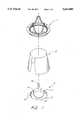
- FIG. 1is a perspective view of the major components in the valve assembly.
- FIG. 2is a view of the geometry of construction of the inner stent.
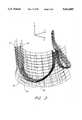
- FIG. 3is a wireframe view of a partially-constructed inner stent, particularly showing the scallop geometry.
- FIG. 4is a perspective view of a portion of the inner stent.
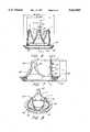
- FIG. 5is a partial cross-sectional view of a portion of an outer stent of the present invention.
- FIG. 6is a side view of the bare inner stent inserted into the outer stent.
- FIG. 7is a cutaway view of the inner and outer stents mated together, showing the relevant clearances between the inner and outer stents.
- FIG. 8is a perspective view of the mated inner and outer stents.
- FIG. 9is an exploded view of the outer stent, securing springs, and covering sock of the present invention.
- FIG. 10is a cross section of a post of the outer stent, showing part of the process of covering the outer stent with a fabric sock.
- FIG. 11is a cross section of a post of the outer stent when fully covered with a fabric sock, showing the bonding of the fabric to the surface of the outer stent.
- FIG. 12a side view illustrating the placement of adhesive between the fabric layers covering the outer stent.
- FIG. 1The components which make up the assembled valve are illustrated in FIG. 1. As illustrated, these components include outer stent 1, tissue 2, and inner stent 3.
- the inner and outer stentshave frames, respectively constructed out of a thermoplastic such as DELRIN or the like using injection molding to form the entire component using unibody construction techniques, instead of welding or the like to attach any protuberances. Unibody construction is less risky to the patient than welding, since welded bonds can break more easily, leading to the injection of valve components or fragments into the bloodstream.
- a thermoplasticsuch as DELRIN or the like
- the outer stent frameis integrated with other components, including a sewing ring and a plurality of garter springs or similar tensioning members, and both frames are covered with a fabric such as DACRON or the like, to form the completed inner and outer stents used in the valve assembly.
- the inner stent frameis preferably constructed with an annular base 12 with three posts 14, 16, and 18 extending from the annular base along the axis of the valve in the direction of blood flow through the valve.
- three such postsare spaced uniformly around the annular base, i.e. such that the centers of adjacent posts are separated by 120 degrees on a circle passing through all three.
- the postsare connected by scalloped walls, such as that illustrated at 20.
- the postsare configured with a plurality of outward-facing members 22. These members are later shaped into tissue alignment members for use in holding the tissue in place while the valve is being assembled.
- the inner stentis covered by a fabric sock made of DACRON or a similar material, the sock being secured by bonding to the base of the inner stent.
- the outer stent 1has a base 99, from which rise scalloped edges 90, which separate the outer stent posts, such as that shown at 92.
- the post 92includes a strut 93 and has a window 94 cut out of it for receiving an inner stent post.
- At the bottom of the windoware fillets 96 and slots 98 segmenting the base of the outer stent into arcuate portions, such as 100.
- An important advantage of the present inventionis that the slots 98 are made as thin as possible to minimize the risk that the sutures used in implanting the valve in the patient will become entangled in the securing springs located around the base of the outer stent.
- the tissue 2is preferably taken from the patient during the surgical procedure, and is preferably pericardium. However, other types of tissue, such as autologous fascia lata or animal or cadaver tissue, may also be used as well.
- tissueAfter being harvested from the patient, the tissue is immersed in a weak glutaraldehyde solution for a brief period of time, and is preferably cut into the proper shape using a die described in the '955 patent, which is fully incorporated herein by reference.
- the current assignee's application Ser. No. 08/169,620, filed Dec. 17, 1993, now U.S. Pat. No. 5,425,741.discloses an improved tissue cutting die, and is also incorporated herein by reference. The use of other means of cutting the tissue, such as a scalpel, is also possible.
- the completed valveis assembled by wrapping the tissue 2 around the inner stent 3, spreading open the outer stent 1, and inserting the inner stent into the outer stent.
- a technique and tools for performing this operationare disclosed in the present assignee's application Ser. No. 08/238,463, filed Dec. 17, 1993, now U.S. Pat. No. 5,522,885, which is incorporated fully herein by reference.
- the design of the inner and outer stentsmust achieve several important objectives. Firstly, the inner and outer stents should remain slightly separated from each other when mated, If they do not, the tissue wrapped on the inner stent will be pinched by the outer stent at the locations where they have insufficient separation, potentially resulting in fatigue tearing and failure of the tissue. Secondly, the tissue wrapped around the inner stent should form three spherically-shaped cusps to distribute the stresses of closure as evenly as possible over the valve. Finally, the inner stent scallops on which the tissue rests should have a horizontal profile to prevent the formation of stress raisers at the points of contact between the tissue and the scallops.
- the outer and inner stentsare designed with a complex, three-dimensional shape corresponding to the desired valve size in order to achieve these goals.
- the designis preferably carried out on a computer using computer-aided design (CAD) software having the capability to represent three-dimensional objects.
- CADcomputer-aided design
- the designerfirst creates a basic geometry for the stents and uses this to define the scallop geometry. This scallop geometry is used to split a rotational surface created to define the stent blank, creating the proper shape for the stent in three dimensions. Necessary surfaces and fillets are finally added to this shape to create the final stent shape. This shape is then input into machine tooling which cuts an electrode into the corresponding shape. Finally, the electrode is used to dissolve a pattern into a block of a suitable metal, such as a nickel-steel alloy, into the final mold for injection-molding the stents.
- a suitable metalsuch as a nickel-steel alloy
- the basic geometry of the inner stent 3is determined by three parameters dependent on the size and strength of the valve desired, namely the post width, the scallop height above the base, and the inner diameter of the valve.
- the post widthis determined from the strength desired for the inner stent and the requirement that the completed valve fully close.
- the postmust be made wide enough to give the inner stent sufficient strength but must not be made so wide that the amount of tissue draped over the inner stent posts is so great that the valve cannot properly close. Representative values for this dimension which have been found acceptable in practice for variously-sized valves are given in column K in Table 1.
- the scallop heightmust be sufficient to achieve three objectives: (1) allow the leaflets of the valve to completely close, (2) provide sufficient flexibility to absorb the shock of valve closure, and (3) distribute the stresses encountered during normal use of the valve evenly throughout the tissue leaflet area.
- the choice of the inner diameter of the valveis based on the size of the patient's annulus, as measured during the surgical procedure with an obturator such as that disclosed in the present assignee's pending application Ser. No. 08/169,618, filed Dec. 17, 1993, now U.S. Pat. No. 5,489,296, which is incorporated by reference herein.
- Values for the scallop height as a function of inner diameterwhich have been determined to be satisfactory in practice can be determined by subtracting dimension D in Table 1, which is the distance from the scallop base to the top of the inner stent posts, from the height of the inner stent, shown as dimension E in Table 1.
- An important advantage of the design methodology of the present inventionis that it allows the use of a single method to easily fabricate size-specific stent kits corresponding to varying annulus diameters.
- the parameters associated with each annulus diameterare easily input into the computer-aided design (CAD) software, which generates a corresponding stent geometry while requiring little user input.
- CADcomputer-aided design
- FIG. 2which illustrates the construction of the inner stent basic geometry from these parameters
- the designertypically operating on a computer having CAD software, creates inner and outer circles 30 and 32 respectively in the x-z plane of the space in which the valve design will be created
- a stent post primitive 34which represents a cross section of the inner stent blank, is rotated about the y-axis to create the stent blank.
- the stent post primitivehas a base section 36, which has a taper, typically approximately 15 degrees, and an upper section 38, to which the outwardly-projecting members 22 are attached.
- the upper section 38is preferably parallel to the y axis.
- the taperhelps bias the valve into a closed position, which enables the valve to close more easily in low-pressure conditions. It also produces a "jet nozzle” effect which reduces turbulence as blood flows through the valve, leading to a smaller net pressure drop across the valve and resulting in less energy loss to the cardiac cycle.
- the stent post widthis shown as dimension A in FIG. 2 and is drawn onto the annulus between the circles 30 and 32 at three equally-spaced intervals separated by 120 degrees, creating locations 37, 39, and 41, which represent the positions of the stent posts of the completed stent.
- posts 37 and 41are shown spaced 30 degrees each from the x-axis to facilitate understanding of the construction process described below.
- a vector, such as that shown at 40is drawn from a point 42 at the intersection of the post edge closest (in the x-direction) to the center of the circles and the circle 32, to a point 44 corresponding to the intersection of the post edge closest (in the x-direction) to the center of the circles and the circle 30.
- This vectoris projected onto the x axis, forming a line having endpoints 46 and 48. This procedure is repeated for post 41, resulting in a projection having endpoints 50 and 52.
- the geometry of the scalloped edge separating posts 37 and 41is determined from the points 46, 48, 50, and 52 that result from the projection operations described above as follows: vertical lines parallel to the y-axis, 54, 56, 58, and 60 are dropped from the respective points 46, 48, 50, and 52, and semicircles 62 and 64 are constructed to intersect, at their edges, the lines 58, 56, 54, and 60 respectively.
- the semicirclesare constructed to be tangent to a line parallel to the x axis and spaced a distance ⁇ , the height of the scallop above the outer stent base, from the base of the stent primitive.
- the union of these semicircles and their respective vertical linesforms curves which will be referred to hereinafter as splines 66 and 68.
- splines 66 and 68As will be seen, these splines, when projected onto the surface of rotation formed with the stent primitive, determine the shape of the scalloped edge separating posts 37 and 41.
- the three-dimensional solid model of the inner stentis created by revolving the inner stent post primitive 34 about the y-axis, thereby creating an inner surface 70 and an outer surface 72 of the inner stent.
- the inner spline 66is then projected onto the inner surface 70 in three dimensions, and the outer spline 68 is projected onto the outer surface 72.
- the resulting spline curves 74 and 76are thus functions of all three spatial variables.
- a ruled surface 78 connecting splines 74 and 76is created.
- This ruled surfacemay be transformed into a b-surface containing many nodes by a suitable surface-fitting algorithm to more precisely define the scallop surface, if required by the particular CAD system employed in the design process.
- the ruled surface 78 or a similar b-surfacerepresents the actual surface in space of the scallop connecting stent posts 37 and 41 and will eventually be sectioned out of the surface of revolution defining the solid model of the inner stent blank.
- the scallop profileis perpendicular to the axis of the stent, i.e. that a line connecting the inner and outer surfaces of the inner stent along the surface defining the scallop is always parallel to the x-z plane at all positions along the scallop. This feature permits the tissue, which is draped over the scallops, to contact the inner stent along its entire width, thereby preventing the formation of possible points of fatigue on the tissue.
- the inner stentis designed so that cusps of the valve are spherical sections.
- the arcs 62 and 64are chosen to be circular because such a geometry results in a spherical configuration for each cusp of the heart valve. This spherical configuration is important in ensuring adequate stress distribution throughout the tissue comprising the valve leaflets.
- ruled surface 78After the creation of the ruled surface 78 between the stent posts 37 and 41, two other ruled surfaces constructed in an identical fashion to the ruled surface 78 are added between the other stent post 39 and the posts 37 and 41. These surfaces are used to form the scallops by splitting the solid model of the inner stent blank at their intersection with the solid inner stent model.
- the finished three-dimensional model of the inner stentwhich is output to programmable tooling, is created by deleting the remaining surfaces and adding the fillets 80 and 82 to the inner stent posts, as shown in FIG. 4, to smooth the upper surfaces of each of the posts.
- the outward-facing tissue alignment members 22are also added.
- the programmable toolingis used to fabricate an electrode having a shape corresponding to that output by the CAD system. This electrode dissolves a pattern into a block of a suitable alloy into the proper shape to create the final injection mold for the inner stent.
- the outer stent post primitive 84is created with a tapered portion 86 and a vertical portion 88.
- the lower portion of the outer stent primitiveis displaced outwardly a suitable distance, typically 20 mils, from the location of the corresponding inner stent primitive 34, and the outer stent blank is revolved about the y-axis to create an outer stent solid model (not shown).
- the solid modelis cut by calculated ruled or b-surfaces defining the scallops, and the required fillets are added to the final model.
- the scalloped edges 90are created somewhat differently from those of the inner stent, however.
- An important objective in the design of the outer stent 1is the maintenance of sufficient clearance between it and the inner stent 3 to prevent the tissue 2 wrapped around the inner stent from being pinched by the outer stent when the stents are mated together during the valve assembly process. Such pinching could lead to the formation of stress raisers in the tissue and ultimately result in tearing of the valve tissue. As seen in FIGS. 6 and 7, unwanted pinching could occur, for example, in the radially-outward direction at the base of both stents at location 95, between the posts of the inner stent and the windows 94 of the outer stent in both the radial and tangential directions at location 97, or anywhere in the volume formed between the inner and outer stents connecting these locations. It is thus important to provide sufficient clearance along the entire inner/outer stent mating region, which passes through these locations.
- the outer stent designmust also simultaneously achieve the objective of providing sufficient strength to the posts 92 to withstand the wear the valve will be subjected to over the life of its user. Both of these objectives are advantageously realized by forming the window 94 into a spaded shape by including the fillet 96 and slightly deforming the ruled or b-surfaces used to create the inner stent scalloped edges to contain a cusp, as shown at numeral 90 in FIG. 8.
- the spaded window shapeallows the outer stent posts to maintain sufficient clearance in both the tangential and radial directions with the inner stent posts and the tissue wrapped thereon, while the cusp-shaped scallop design imparts sufficient thickness to each of the struts 93 to provide the required strength to each post 92.
- the clearance required between the inner and outer stents along the mating surfaces, as at locations 95 and 97,is typically approximately 20 mils if a thin DACRON sock is used to cover the inner and outer stents, and tissue having a thickness of approximately 15 mils is used to fabricate the valve. Such a value for the clearance also allows the tissue to penetrate the interstices of the DACRON cover, resulting in less slippage between the tissue and the stents.
- Other dimensions for the inner and outer stentsare identified with the letters A-K in FIGS. 6 and 7. These dimensions are proportional to the size of the annulus to be fitted with the valve. Table 1 shows the preferable relationship between these dimensions (in inches) and a variety of possible sizes of the annulus to be fitted:
- valve sizesare possible, such as valves configured for young children, where the annulus size might be as small as 14 mm.
- Table 1The dimensions in Table 1 have proven to be acceptable in practice, and allow the formation of spherical cusps, which have the advantages described above, from the tissue 2 in the completed valve.
- FIGS. 10-11Other features incorporated into the outer stent are illustrated in FIGS. 10-11.
- the base 99 of the outer stentis provided with a plurality of garter springs 102 or other securing members extending around the length of its base.
- the garter springs 102provide the tension force which secures the inner and outer stents together.
- More than one garter springis advantageously used in the present invention to increase the redundancy of the valve. If one garter spring breaks, the presence of another spring ensures that the outer stent is still able to fulfill its role of clamping the tissue around the inner stent. Such a result would not be possible if only one spring is used around the base of the outer stent.
- Another advantageous feature of the present inventionis the provision of a wedge-shaped sewing ring 104, which is attached to the annular base of the outer stent.
- the sewing ring 104provides a site on the valve assembly for securing it into the patient's annulus by use of sutures or similar means.
- a wedge-shaped sewing ringhas been found to fit better into the aortic root of a patient than other shapes when the valve is used as an aortic replacement.
- the outer stentis covered with a DACRON sock 106.
- Covering the stent frameaccomplishes the purpose of isolating nonbiological material, such as the stent frame thermoplastic, from the body. This also helps avoid the problem of thromboembolism, which occurs with the use of mechanical valves. It also accomplishes the purpose of promoting tissue ingrowth into the interstices of the fabric, to further isolate the nonbiological material from the body, and integrate the valve into the heart. Additionally, it accomplishes the purpose of providing an interface to the tissue clamped between the stents which is gentle, and which helps nourish the tissue and promote its viability by allowing free passage of blood to the tissue.
- a three-fingered DACRON sockis formed by heat seaming inner and outer sections of DACRON fabric together utilizing either hot wire or ultrasonic techniques. Alternatively, the sock can be woven as one piece or sewn. The sock is then pulled over the outer stent frame and its outer section 107 is secured at the outer stent base at weld 108. Next, the sock's inner section 109 is wrapped around the inner surface of the outer stent, as well as around the outer stent base itself. The inner layer is secured to the top of the base at a second weld 110.
- the present inventionadvantageously utilizes a medical-grade adhesive, such as RTV silicone adhesive, to secure the outer and inner sections of the sock together along segments such as 112. Adhesive is applied to the inner or outer section along the portions of the outer stent base overlying a slot.
- a medical-grade adhesivesuch as RTV silicone adhesive
Landscapes
- Health & Medical Sciences (AREA)
- Engineering & Computer Science (AREA)
- Cardiology (AREA)
- Biomedical Technology (AREA)
- Heart & Thoracic Surgery (AREA)
- Transplantation (AREA)
- Oral & Maxillofacial Surgery (AREA)
- Vascular Medicine (AREA)
- Life Sciences & Earth Sciences (AREA)
- Animal Behavior & Ethology (AREA)
- General Health & Medical Sciences (AREA)
- Public Health (AREA)
- Veterinary Medicine (AREA)
- Manufacturing & Machinery (AREA)
- Prostheses (AREA)
Abstract
Description
TABLE 1 __________________________________________________________________________SIZE (MM) A DIA B DIA C DIA D E F G H J K __________________________________________________________________________17 .641 .895 .482 .299 .373 .454 .022 .021 .085 .049 19 .708 .992 .540 .342 .419 .506 .025 .021 .090 .054 21 .773 1.079 .592 .378 .460 .553 .027 .023 .092 .060 23 .844 1.180 .650 .414 .505 .606 .030 .025 .103 .060 25 .915 1.277 .708 .450 .549 .657 .033 .027 .115 .069 TOL. -.040 +.040 -.005 +.005 +.005 +.005 +.002 -.003 +.005 -.005 __________________________________________________________________________
Claims (8)
Priority Applications (1)
| Application Number | Priority Date | Filing Date | Title |
|---|---|---|---|
| US08/475,030US5612885A (en) | 1993-12-17 | 1995-06-06 | Method for constructing a heart valve stent |
Applications Claiming Priority (2)
| Application Number | Priority Date | Filing Date | Title |
|---|---|---|---|
| US08/169,336US5755782A (en) | 1991-01-24 | 1993-12-17 | Stents for autologous tissue heart valve |
| US08/475,030US5612885A (en) | 1993-12-17 | 1995-06-06 | Method for constructing a heart valve stent |
Related Parent Applications (1)
| Application Number | Title | Priority Date | Filing Date |
|---|---|---|---|
| US08/169,336DivisionUS5755782A (en) | 1991-01-24 | 1993-12-17 | Stents for autologous tissue heart valve |
Publications (1)
| Publication Number | Publication Date |
|---|---|
| US5612885Atrue US5612885A (en) | 1997-03-18 |
Family
ID=22615244
Family Applications (2)
| Application Number | Title | Priority Date | Filing Date |
|---|---|---|---|
| US08/169,336Expired - LifetimeUS5755782A (en) | 1991-01-24 | 1993-12-17 | Stents for autologous tissue heart valve |
| US08/475,030Expired - LifetimeUS5612885A (en) | 1993-12-17 | 1995-06-06 | Method for constructing a heart valve stent |
Family Applications Before (1)
| Application Number | Title | Priority Date | Filing Date |
|---|---|---|---|
| US08/169,336Expired - LifetimeUS5755782A (en) | 1991-01-24 | 1993-12-17 | Stents for autologous tissue heart valve |
Country Status (6)
| Country | Link |
|---|---|
| US (2) | US5755782A (en) |
| EP (1) | EP0734236A1 (en) |
| JP (1) | JPH09508537A (en) |
| CA (1) | CA2179263A1 (en) |
| TW (1) | TW249198B (en) |
| WO (1) | WO1995016412A1 (en) |
Cited By (35)
| Publication number | Priority date | Publication date | Assignee | Title |
|---|---|---|---|---|
| US5741215A (en)* | 1993-09-10 | 1998-04-21 | The University Of Queensland | Stereolithographic anatomical modelling process |
| US6045576A (en)* | 1997-09-16 | 2000-04-04 | Baxter International Inc. | Sewing ring having increased annular coaptation |
| US6162237A (en)* | 1999-04-19 | 2000-12-19 | Chan; Winston Kam Yew | Temporary intravascular stent for use in retrohepatic IVC or hepatic vein injury |
| US6164339A (en)* | 1998-08-14 | 2000-12-26 | Prodesco, Inc. | Method of forming a woven textile |
| US6250308B1 (en) | 1998-06-16 | 2001-06-26 | Cardiac Concepts, Inc. | Mitral valve annuloplasty ring and method of implanting |
| US6309417B1 (en) | 1999-05-12 | 2001-10-30 | Paul A. Spence | Heart valve and apparatus for replacement thereof |
| US6334873B1 (en) | 1998-09-28 | 2002-01-01 | Autogenics | Heart valve having tissue retention with anchors and an outer sheath |
| US6348068B1 (en)* | 1999-07-23 | 2002-02-19 | Sulzer Carbomedics Inc. | Multi-filament valve stent for a cardisc valvular prosthesis |
| US6454799B1 (en)* | 2000-04-06 | 2002-09-24 | Edwards Lifesciences Corporation | Minimally-invasive heart valves and methods of use |
| US6491511B1 (en) | 1999-10-14 | 2002-12-10 | The International Heart Institute Of Montana Foundation | Mold to form stent-less replacement heart valves from biological membranes |
| US20030209835A1 (en)* | 2002-05-10 | 2003-11-13 | Iksoo Chun | Method of forming a tubular membrane on a structural frame |
| US20030225447A1 (en)* | 2002-05-10 | 2003-12-04 | Majercak David Christopher | Method of making a medical device having a thin wall tubular membrane over a structural frame |
| US20040034408A1 (en)* | 2002-05-10 | 2004-02-19 | Majercak David Christopher | Method of placing a tubular membrane on a structural frame |
| US6709457B1 (en) | 1999-11-24 | 2004-03-23 | St. Jude Medical, Inc. | Attachment of suture cuff to prosthetic heart valve |
| US20040093070A1 (en)* | 2002-05-10 | 2004-05-13 | Hikmat Hojeibane | Frame based unidirectional flow prosthetic implant |
| US20040176678A1 (en)* | 2001-04-30 | 2004-09-09 | Chase Medical, L.P. | System and method for facilitating cardiac intervention |
| US20040209692A1 (en)* | 2003-04-17 | 2004-10-21 | Grips Elektronik G.M.B.H. | Player insert for a gaming machine, a gaming system and a method of operating a gaming system |
| US20050240262A1 (en)* | 2002-05-03 | 2005-10-27 | The General Hospital Corporation | Involuted endovascular valve and method of construction |
| US7070616B2 (en) | 2003-10-31 | 2006-07-04 | Cordis Corporation | Implantable valvular prosthesis |
| US20060147487A1 (en)* | 2004-12-31 | 2006-07-06 | Jamie Henderson | Smart textile vascular graft |
| US20070168022A1 (en)* | 2006-01-17 | 2007-07-19 | Eldridge Charles J | Heart valve |
| US7347869B2 (en) | 2003-10-31 | 2008-03-25 | Cordis Corporation | Implantable valvular prosthesis |
| US20090139914A1 (en)* | 2006-11-01 | 2009-06-04 | Raf Technology, Inc. | Mailpiece reject processing of first pass dps rejects |
| US7840393B1 (en)* | 2000-10-04 | 2010-11-23 | Trivascular, Inc. | Virtual prototyping and testing for medical device development |
| US8066755B2 (en) | 2007-09-26 | 2011-11-29 | Trivascular, Inc. | System and method of pivoted stent deployment |
| US8083789B2 (en) | 2007-11-16 | 2011-12-27 | Trivascular, Inc. | Securement assembly and method for expandable endovascular device |
| US8226701B2 (en) | 2007-09-26 | 2012-07-24 | Trivascular, Inc. | Stent and delivery system for deployment thereof |
| US8328861B2 (en) | 2007-11-16 | 2012-12-11 | Trivascular, Inc. | Delivery system and method for bifurcated graft |
| US20140005773A1 (en)* | 2011-02-18 | 2014-01-02 | David J. Wheatley | Heart Valve |
| US8663309B2 (en) | 2007-09-26 | 2014-03-04 | Trivascular, Inc. | Asymmetric stent apparatus and method |
| US8992595B2 (en) | 2012-04-04 | 2015-03-31 | Trivascular, Inc. | Durable stent graft with tapered struts and stable delivery methods and devices |
| US9498363B2 (en) | 2012-04-06 | 2016-11-22 | Trivascular, Inc. | Delivery catheter for endovascular device |
| CN106980729A (en)* | 2015-07-24 | 2017-07-25 | 安徽工业大学 | A kind of continuous casting breakout prediction method based on mixed model |
| US10159557B2 (en) | 2007-10-04 | 2018-12-25 | Trivascular, Inc. | Modular vascular graft for low profile percutaneous delivery |
| US20190373863A1 (en)* | 2017-01-31 | 2019-12-12 | The Board Of Regents Of The University Of Oklahoma | Animal wound model and methods of use |
Families Citing this family (80)
| Publication number | Priority date | Publication date | Assignee | Title |
|---|---|---|---|---|
| DK124690D0 (en)* | 1990-05-18 | 1990-05-18 | Henning Rud Andersen | FAT PROTECTION FOR IMPLEMENTATION IN THE BODY FOR REPLACEMENT OF NATURAL FLEET AND CATS FOR USE IN IMPLEMENTING A SUCH FAT PROTECTION |
| US5865723A (en)* | 1995-12-29 | 1999-02-02 | Ramus Medical Technologies | Method and apparatus for forming vascular prostheses |
| US6494904B1 (en) | 1996-12-27 | 2002-12-17 | Ramus Medical Technologies | Method and apparatus for forming vascular prostheses |
| US5928281A (en) | 1997-03-27 | 1999-07-27 | Baxter International Inc. | Tissue heart valves |
| AU6786400A (en)* | 1999-08-16 | 2001-03-13 | Citron Limited | Autologous tissue suture ring used in heart valve implantation |
| US6598307B2 (en) | 1999-11-17 | 2003-07-29 | Jack W. Love | Device and method for assessing the geometry of a heart valve |
| NL1014095C2 (en)* | 2000-01-17 | 2001-07-18 | Cornelis Hendrikus Anna Witten | Implant valve for implantation into a blood vessel. |
| US8366769B2 (en) | 2000-06-01 | 2013-02-05 | Edwards Lifesciences Corporation | Low-profile, pivotable heart valve sewing ring |
| US6409758B2 (en) | 2000-07-27 | 2002-06-25 | Edwards Lifesciences Corporation | Heart valve holder for constricting the valve commissures and methods of use |
| US6425902B1 (en) | 2001-05-04 | 2002-07-30 | Cardiomend Llc | Surgical instrument for heart valve reconstruction |
| US6893460B2 (en) | 2001-10-11 | 2005-05-17 | Percutaneous Valve Technologies Inc. | Implantable prosthetic valve |
| US6755857B2 (en) | 2001-12-12 | 2004-06-29 | Sulzer Carbomedics Inc. | Polymer heart valve with perforated stent and sewing cuff |
| US7201771B2 (en) | 2001-12-27 | 2007-04-10 | Arbor Surgical Technologies, Inc. | Bioprosthetic heart valve |
| US7959674B2 (en) | 2002-07-16 | 2011-06-14 | Medtronic, Inc. | Suture locking assembly and method of use |
| US8551162B2 (en) | 2002-12-20 | 2013-10-08 | Medtronic, Inc. | Biologically implantable prosthesis |
| US8021421B2 (en) | 2003-08-22 | 2011-09-20 | Medtronic, Inc. | Prosthesis heart valve fixturing device |
| US7556647B2 (en) | 2003-10-08 | 2009-07-07 | Arbor Surgical Technologies, Inc. | Attachment device and methods of using the same |
| US7871435B2 (en) | 2004-01-23 | 2011-01-18 | Edwards Lifesciences Corporation | Anatomically approximate prosthetic mitral heart valve |
| US20050228494A1 (en)* | 2004-03-29 | 2005-10-13 | Salvador Marquez | Controlled separation heart valve frame |
| US8216299B2 (en)* | 2004-04-01 | 2012-07-10 | Cook Medical Technologies Llc | Method to retract a body vessel wall with remodelable material |
| WO2005099623A1 (en)* | 2004-04-08 | 2005-10-27 | Cook Incorporated | Implantable medical device with optimized shape |
| US8574257B2 (en) | 2005-02-10 | 2013-11-05 | Edwards Lifesciences Corporation | System, device, and method for providing access in a cardiovascular environment |
| US7513909B2 (en) | 2005-04-08 | 2009-04-07 | Arbor Surgical Technologies, Inc. | Two-piece prosthetic valves with snap-in connection and methods for use |
| JP4912395B2 (en) | 2005-05-24 | 2012-04-11 | エドワーズ ライフサイエンシーズ コーポレイション | Rapid placement prosthetic heart valve |
| US8211169B2 (en) | 2005-05-27 | 2012-07-03 | Medtronic, Inc. | Gasket with collar for prosthetic heart valves and methods for using them |
| US7776084B2 (en)* | 2005-07-13 | 2010-08-17 | Edwards Lifesciences Corporation | Prosthetic mitral heart valve having a contoured sewing ring |
| WO2007016165A1 (en)* | 2005-07-29 | 2007-02-08 | Cook Incorporated | Elliptical implantable device |
| US7967857B2 (en) | 2006-01-27 | 2011-06-28 | Medtronic, Inc. | Gasket with spring collar for prosthetic heart valves and methods for making and using them |
| JP2009535128A (en) | 2006-04-29 | 2009-10-01 | アーバー・サージカル・テクノロジーズ・インコーポレイテッド | Multi-part prosthetic heart valve assembly and apparatus and method for delivering the same |
| US8021161B2 (en)* | 2006-05-01 | 2011-09-20 | Edwards Lifesciences Corporation | Simulated heart valve root for training and testing |
| US20080177380A1 (en)* | 2007-01-19 | 2008-07-24 | Starksen Niel F | Methods and devices for heart tissue repair |
| US7846199B2 (en) | 2007-11-19 | 2010-12-07 | Cook Incorporated | Remodelable prosthetic valve |
| PL4223257T3 (en)* | 2008-06-06 | 2024-09-23 | Edwards Lifesciences Corporation | LOW-PROFILE TRANSCATHETIC HEART VALVE |
| US8449625B2 (en) | 2009-10-27 | 2013-05-28 | Edwards Lifesciences Corporation | Methods of measuring heart valve annuluses for valve replacement |
| EP2370138B1 (en) | 2008-11-25 | 2020-12-30 | Edwards Lifesciences Corporation | Apparatus for in situ expansion of prosthetic device |
| US8308798B2 (en) | 2008-12-19 | 2012-11-13 | Edwards Lifesciences Corporation | Quick-connect prosthetic heart valve and methods |
| US9980818B2 (en) | 2009-03-31 | 2018-05-29 | Edwards Lifesciences Corporation | Prosthetic heart valve system with positioning markers |
| US8348998B2 (en) | 2009-06-26 | 2013-01-08 | Edwards Lifesciences Corporation | Unitary quick connect prosthetic heart valve and deployment system and methods |
| FR2951549B1 (en) | 2009-10-15 | 2013-08-23 | Olivier Schussler | PROCESS FOR OBTAINING IMPLANTABLE MEDICAL BIOPROTHESES |
| US8986374B2 (en) | 2010-05-10 | 2015-03-24 | Edwards Lifesciences Corporation | Prosthetic heart valve |
| US9554901B2 (en) | 2010-05-12 | 2017-01-31 | Edwards Lifesciences Corporation | Low gradient prosthetic heart valve |
| US8641757B2 (en) | 2010-09-10 | 2014-02-04 | Edwards Lifesciences Corporation | Systems for rapidly deploying surgical heart valves |
| US9370418B2 (en) | 2010-09-10 | 2016-06-21 | Edwards Lifesciences Corporation | Rapidly deployable surgical heart valves |
| US9125741B2 (en) | 2010-09-10 | 2015-09-08 | Edwards Lifesciences Corporation | Systems and methods for ensuring safe and rapid deployment of prosthetic heart valves |
| US8845720B2 (en) | 2010-09-27 | 2014-09-30 | Edwards Lifesciences Corporation | Prosthetic heart valve frame with flexible commissures |
| US8690764B2 (en) | 2010-10-20 | 2014-04-08 | Covidien Lp | Endoscope cleaner |
| US20120116496A1 (en) | 2010-11-05 | 2012-05-10 | Chuter Timothy A | Stent structures for use with valve replacements |
| US8945209B2 (en) | 2011-05-20 | 2015-02-03 | Edwards Lifesciences Corporation | Encapsulated heart valve |
| US9078747B2 (en) | 2011-12-21 | 2015-07-14 | Edwards Lifesciences Corporation | Anchoring device for replacing or repairing a heart valve |
| EP3281608B1 (en)* | 2012-02-10 | 2020-09-16 | CVDevices, LLC | Medical product comprising a frame and visceral pleura |
| US9693862B2 (en) | 2012-07-31 | 2017-07-04 | Edwards Lifesciences Corporation | Holders for prosthetic heart valves |
| WO2014145811A1 (en) | 2013-03-15 | 2014-09-18 | Edwards Lifesciences Corporation | Valved aortic conduits |
| US11007058B2 (en) | 2013-03-15 | 2021-05-18 | Edwards Lifesciences Corporation | Valved aortic conduits |
| US9468527B2 (en) | 2013-06-12 | 2016-10-18 | Edwards Lifesciences Corporation | Cardiac implant with integrated suture fasteners |
| US9919137B2 (en) | 2013-08-28 | 2018-03-20 | Edwards Lifesciences Corporation | Integrated balloon catheter inflation system |
| EP3046512B1 (en) | 2013-09-20 | 2024-03-06 | Edwards Lifesciences Corporation | Heart valves with increased effective orifice area |
| US20150122687A1 (en) | 2013-11-06 | 2015-05-07 | Edwards Lifesciences Corporation | Bioprosthetic heart valves having adaptive seals to minimize paravalvular leakage |
| US9549816B2 (en) | 2014-04-03 | 2017-01-24 | Edwards Lifesciences Corporation | Method for manufacturing high durability heart valve |
| US9585752B2 (en) | 2014-04-30 | 2017-03-07 | Edwards Lifesciences Corporation | Holder and deployment system for surgical heart valves |
| CA2914094C (en) | 2014-06-20 | 2021-01-05 | Edwards Lifesciences Corporation | Surgical heart valves identifiable post-implant |
| USD867594S1 (en) | 2015-06-19 | 2019-11-19 | Edwards Lifesciences Corporation | Prosthetic heart valve |
| WO2016022797A1 (en) | 2014-08-06 | 2016-02-11 | Edwards Lifesciences Corporation | Multi-lumen cannulae |
| CA2989437C (en) | 2015-07-02 | 2023-08-08 | Edwards Lifesciences Corporation | Hybrid heart valves adapted for post-implant expansion |
| CN107920894B (en) | 2015-07-02 | 2020-04-28 | 爱德华兹生命科学公司 | Integrated hybrid heart valve |
| ITUB20152409A1 (en) | 2015-07-22 | 2017-01-22 | Sorin Group Italia Srl | VALVE SLEEVE FOR VALVULAR PROSTHESIS AND CORRESPONDING DEVICE |
| CN108135592B (en) | 2015-09-02 | 2021-05-14 | 爱德华兹生命科学公司 | Spacer for securing a transcatheter valve to a bioprosthetic cardiac structure |
| US10080653B2 (en) | 2015-09-10 | 2018-09-25 | Edwards Lifesciences Corporation | Limited expansion heart valve |
| US10667904B2 (en) | 2016-03-08 | 2020-06-02 | Edwards Lifesciences Corporation | Valve implant with integrated sensor and transmitter |
| US10456245B2 (en) | 2016-05-16 | 2019-10-29 | Edwards Lifesciences Corporation | System and method for applying material to a stent |
| USD846122S1 (en) | 2016-12-16 | 2019-04-16 | Edwards Lifesciences Corporation | Heart valve sizer |
| US10463485B2 (en) | 2017-04-06 | 2019-11-05 | Edwards Lifesciences Corporation | Prosthetic valve holders with automatic deploying mechanisms |
| EP3614969B1 (en) | 2017-04-28 | 2023-05-03 | Edwards Lifesciences Corporation | Prosthetic heart valve with collapsible holder |
| EP3694562A2 (en) | 2017-10-13 | 2020-08-19 | Edwards Lifesciences Corporation | Method for sterilizing heart valves |
| EP3743016B1 (en) | 2018-01-23 | 2024-10-02 | Edwards Lifesciences Corporation | Prosthetic valve holders, systems, and methods |
| USD908874S1 (en) | 2018-07-11 | 2021-01-26 | Edwards Lifesciences Corporation | Collapsible heart valve sizer |
| US11412921B2 (en) | 2018-10-02 | 2022-08-16 | Covidien Lp | Multi lumen access device |
| WO2020163145A1 (en) | 2019-02-05 | 2020-08-13 | Edwards Lifesciences Corporation | Prosthetic heart valve with suture loop preventing member |
| US11357542B2 (en) | 2019-06-21 | 2022-06-14 | Covidien Lp | Valve assembly and retainer for surgical access assembly |
| WO2021025979A1 (en) | 2019-08-02 | 2021-02-11 | Edwards Lifesciences Corporation | Rotary application of fibrous material to medical devices |
| CR20210655A (en) | 2019-12-16 | 2022-06-02 | Edwards Lifesciences Corp | Valve holder assembly with suture looping protection |
Citations (40)
| Publication number | Priority date | Publication date | Assignee | Title |
|---|---|---|---|---|
| US2822819A (en)* | 1953-08-07 | 1958-02-11 | Geeraert Corp | Cuspate check valve |
| US3022802A (en)* | 1954-11-08 | 1962-02-27 | Harvey M Lewis | Reenforced hollow circular plastic objects |
| GB1189399A (en)* | 1967-08-05 | 1970-04-22 | Amis | Non-Return Valve |
| US3532016A (en)* | 1968-10-18 | 1970-10-06 | Warren Zeph Lane | Method and apparatus for cutting autogenous tissue for cardiac valve repair |
| US3548418A (en)* | 1968-05-03 | 1970-12-22 | Cutter Lab | Graft valve transplantation for human hearts and graft-support ring therefor |
| US3570014A (en)* | 1968-09-16 | 1971-03-16 | Warren D Hancock | Stent for heart valve |
| GB1264472A (en)* | 1969-09-25 | 1972-02-23 | ||
| GB1264471A (en)* | 1968-01-12 | 1972-02-23 | ||
| US3714671A (en)* | 1970-11-30 | 1973-02-06 | Cutter Lab | Tissue-type heart valve with a graft support ring or stent |
| US3755823A (en)* | 1971-04-23 | 1973-09-04 | Hancock Laboratories Inc | Flexible stent for heart valve |
| US3824140A (en)* | 1971-06-11 | 1974-07-16 | Linde Ag | Method of insulating ducts |
| US4035849A (en)* | 1975-11-17 | 1977-07-19 | William W. Angell | Heart valve stent and process for preparing a stented heart valve prosthesis |
| FR2337543A1 (en)* | 1976-01-09 | 1977-08-05 | American Hospital Supply Corp | BIOPROTHETIC HEART VALVE SUPPORTED BY A FLEXIBLE FRAME |
| US4084268A (en)* | 1976-04-22 | 1978-04-18 | Shiley Laboratories, Incorporated | Prosthetic tissue heart valve |
| FR2377543A1 (en)* | 1977-01-14 | 1978-08-11 | Danescu Septimius | DEVICE FOR ASSEMBLING PROFILE BARS |
| US4172295A (en)* | 1978-01-27 | 1979-10-30 | Shiley Scientific, Inc. | Tri-cuspid three-tissue prosthetic heart valve |
| US4192020A (en)* | 1975-05-07 | 1980-03-11 | Washington University | Heart valve prosthesis |
| US4247292A (en)* | 1979-06-06 | 1981-01-27 | Angell William W | Natural tissue heart valve fixation process |
| US4297749A (en)* | 1977-04-25 | 1981-11-03 | Albany International Corp. | Heart valve prosthesis |
| US4388735A (en)* | 1980-11-03 | 1983-06-21 | Shiley Inc. | Low profile prosthetic xenograft heart valve |
| US4427470A (en)* | 1981-09-01 | 1984-01-24 | University Of Utah | Vacuum molding technique for manufacturing a ventricular assist device |
| US4470157A (en)* | 1981-04-27 | 1984-09-11 | Love Jack W | Tricuspid prosthetic tissue heart valve |
| US4478661A (en)* | 1981-03-20 | 1984-10-23 | Dayco Corporation | Method of making a reinforced collapsible hose construction |
| US4490859A (en)* | 1982-01-20 | 1985-01-01 | University Of Sheffield | Artificial heart valves |
| US4501030A (en)* | 1981-08-17 | 1985-02-26 | American Hospital Supply Corporation | Method of leaflet attachment for prosthetic heart valves |
| US4512471A (en)* | 1984-04-06 | 1985-04-23 | Angicor Limited | Storage unit |
| SU1116573A1 (en)* | 1983-01-07 | 1985-07-15 | Предприятие П/Я А-1619 | Bioprosthesis of heart valve |
| US4597767A (en)* | 1982-12-15 | 1986-07-01 | Andrew Lenkei | Split leaflet heart valve |
| US4605407A (en)* | 1983-01-11 | 1986-08-12 | The University Of Sheffield | Heart valve replacements |
| US4687483A (en)* | 1984-09-28 | 1987-08-18 | University Court Of The University Of Glasgow | Heart valve prosthesis |
| US4725274A (en)* | 1986-10-24 | 1988-02-16 | Baxter Travenol Laboratories, Inc. | Prosthetic heart valve |
| US4838288A (en)* | 1988-03-14 | 1989-06-13 | Pioneering Technologies, Inc. | Heart valve and xenograft washing system |
| US4851000A (en)* | 1987-07-31 | 1989-07-25 | Pacific Biomedical Holdings, Ltd. | Bioprosthetic valve stent |
| US5037434A (en)* | 1990-04-11 | 1991-08-06 | Carbomedics, Inc. | Bioprosthetic heart valve with elastic commissures |
| US5147391A (en)* | 1990-04-11 | 1992-09-15 | Carbomedics, Inc. | Bioprosthetic heart valve with semi-permeable commissure posts and deformable leaflets |
| US5163955A (en)* | 1991-01-24 | 1992-11-17 | Autogenics | Rapid assembly, concentric mating stent, tissue heart valve with enhanced clamping and tissue alignment |
| US5197979A (en)* | 1990-09-07 | 1993-03-30 | Baxter International Inc. | Stentless heart valve and holder |
| US5345546A (en)* | 1990-12-20 | 1994-09-06 | Ricoh Company, Ltd. | Method and apparatus for generating fillet surface between two surfaces |
| US5401257A (en)* | 1993-04-27 | 1995-03-28 | Boston Scientific Corporation | Ureteral stents, drainage tubes and the like |
| US5480424A (en)* | 1993-11-01 | 1996-01-02 | Cox; James L. | Heart valve replacement using flexible tubes |
Family Cites Families (6)
| Publication number | Priority date | Publication date | Assignee | Title |
|---|---|---|---|---|
| US1266423A (en)* | 1917-07-26 | 1918-05-14 | Charles Frederick Denise | Device for holding strainers over cream-separators. |
| FR766025A (en)* | 1933-09-16 | 1934-06-20 | Masch Ind A G Johann Klinger | Automatic hose clamp |
| US2708950A (en)* | 1953-04-13 | 1955-05-24 | P T Mcdonough | Pipe end cover and protector |
| US5036312A (en)* | 1989-01-03 | 1991-07-30 | Motorola, Inc. | Spring failure detection and safety system |
| US5060716A (en)* | 1989-03-31 | 1991-10-29 | Heine William F | Heat dissipating device and combination including same |
| BR9205978A (en)* | 1991-05-08 | 1994-07-26 | Nika Health Products Ltd | Process and apparatus for the production of a heart valve prosthesis |
- 1993
- 1993-12-17USUS08/169,336patent/US5755782A/ennot_activeExpired - Lifetime
- 1994
- 1994-06-17TWTW083105524Apatent/TW249198B/enactive
- 1994-12-16CACA002179263Apatent/CA2179263A1/ennot_activeAbandoned
- 1994-12-16EPEP95906050Apatent/EP0734236A1/ennot_activeWithdrawn
- 1994-12-16WOPCT/US1994/014720patent/WO1995016412A1/ennot_activeApplication Discontinuation
- 1994-12-16JPJP7517023Apatent/JPH09508537A/enactivePending
- 1995
- 1995-06-06USUS08/475,030patent/US5612885A/ennot_activeExpired - Lifetime
Patent Citations (45)
| Publication number | Priority date | Publication date | Assignee | Title |
|---|---|---|---|---|
| US2822819A (en)* | 1953-08-07 | 1958-02-11 | Geeraert Corp | Cuspate check valve |
| US3022802A (en)* | 1954-11-08 | 1962-02-27 | Harvey M Lewis | Reenforced hollow circular plastic objects |
| GB1189399A (en)* | 1967-08-05 | 1970-04-22 | Amis | Non-Return Valve |
| GB1264471A (en)* | 1968-01-12 | 1972-02-23 | ||
| US3548418A (en)* | 1968-05-03 | 1970-12-22 | Cutter Lab | Graft valve transplantation for human hearts and graft-support ring therefor |
| US3570014A (en)* | 1968-09-16 | 1971-03-16 | Warren D Hancock | Stent for heart valve |
| US3532016A (en)* | 1968-10-18 | 1970-10-06 | Warren Zeph Lane | Method and apparatus for cutting autogenous tissue for cardiac valve repair |
| GB1264472A (en)* | 1969-09-25 | 1972-02-23 | ||
| US3714671A (en)* | 1970-11-30 | 1973-02-06 | Cutter Lab | Tissue-type heart valve with a graft support ring or stent |
| US3755823A (en)* | 1971-04-23 | 1973-09-04 | Hancock Laboratories Inc | Flexible stent for heart valve |
| US3824140A (en)* | 1971-06-11 | 1974-07-16 | Linde Ag | Method of insulating ducts |
| US4192020A (en)* | 1975-05-07 | 1980-03-11 | Washington University | Heart valve prosthesis |
| US4035849A (en)* | 1975-11-17 | 1977-07-19 | William W. Angell | Heart valve stent and process for preparing a stented heart valve prosthesis |
| FR2337543A1 (en)* | 1976-01-09 | 1977-08-05 | American Hospital Supply Corp | BIOPROTHETIC HEART VALVE SUPPORTED BY A FLEXIBLE FRAME |
| US4106129A (en)* | 1976-01-09 | 1978-08-15 | American Hospital Supply Corporation | Supported bioprosthetic heart valve with compliant orifice ring |
| US4084268A (en)* | 1976-04-22 | 1978-04-18 | Shiley Laboratories, Incorporated | Prosthetic tissue heart valve |
| FR2377543A1 (en)* | 1977-01-14 | 1978-08-11 | Danescu Septimius | DEVICE FOR ASSEMBLING PROFILE BARS |
| US4297749A (en)* | 1977-04-25 | 1981-11-03 | Albany International Corp. | Heart valve prosthesis |
| US4172295A (en)* | 1978-01-27 | 1979-10-30 | Shiley Scientific, Inc. | Tri-cuspid three-tissue prosthetic heart valve |
| US4247292A (en)* | 1979-06-06 | 1981-01-27 | Angell William W | Natural tissue heart valve fixation process |
| US4388735A (en)* | 1980-11-03 | 1983-06-21 | Shiley Inc. | Low profile prosthetic xenograft heart valve |
| US4478661A (en)* | 1981-03-20 | 1984-10-23 | Dayco Corporation | Method of making a reinforced collapsible hose construction |
| US4470157A (en)* | 1981-04-27 | 1984-09-11 | Love Jack W | Tricuspid prosthetic tissue heart valve |
| US4501030A (en)* | 1981-08-17 | 1985-02-26 | American Hospital Supply Corporation | Method of leaflet attachment for prosthetic heart valves |
| US4427470A (en)* | 1981-09-01 | 1984-01-24 | University Of Utah | Vacuum molding technique for manufacturing a ventricular assist device |
| US4490859A (en)* | 1982-01-20 | 1985-01-01 | University Of Sheffield | Artificial heart valves |
| US4597767A (en)* | 1982-12-15 | 1986-07-01 | Andrew Lenkei | Split leaflet heart valve |
| SU1116573A1 (en)* | 1983-01-07 | 1985-07-15 | Предприятие П/Я А-1619 | Bioprosthesis of heart valve |
| US4605407A (en)* | 1983-01-11 | 1986-08-12 | The University Of Sheffield | Heart valve replacements |
| US4512471A (en)* | 1984-04-06 | 1985-04-23 | Angicor Limited | Storage unit |
| EP0179562B1 (en)* | 1984-09-28 | 1989-07-12 | The University of Glasgow, University Court | A heart valve prosthesis |
| US4687483A (en)* | 1984-09-28 | 1987-08-18 | University Court Of The University Of Glasgow | Heart valve prosthesis |
| US4725274A (en)* | 1986-10-24 | 1988-02-16 | Baxter Travenol Laboratories, Inc. | Prosthetic heart valve |
| US4851000A (en)* | 1987-07-31 | 1989-07-25 | Pacific Biomedical Holdings, Ltd. | Bioprosthetic valve stent |
| US4838288A (en)* | 1988-03-14 | 1989-06-13 | Pioneering Technologies, Inc. | Heart valve and xenograft washing system |
| US5147391A (en)* | 1990-04-11 | 1992-09-15 | Carbomedics, Inc. | Bioprosthetic heart valve with semi-permeable commissure posts and deformable leaflets |
| WO1991015167A1 (en)* | 1990-04-11 | 1991-10-17 | Carbomedics, Inc. | Bioprosthetic heart valve with elastic commissures |
| US5037434A (en)* | 1990-04-11 | 1991-08-06 | Carbomedics, Inc. | Bioprosthetic heart valve with elastic commissures |
| US5197979A (en)* | 1990-09-07 | 1993-03-30 | Baxter International Inc. | Stentless heart valve and holder |
| US5345546A (en)* | 1990-12-20 | 1994-09-06 | Ricoh Company, Ltd. | Method and apparatus for generating fillet surface between two surfaces |
| US5163955A (en)* | 1991-01-24 | 1992-11-17 | Autogenics | Rapid assembly, concentric mating stent, tissue heart valve with enhanced clamping and tissue alignment |
| US5326371A (en)* | 1991-01-24 | 1994-07-05 | Autogenics | Rapid assembly, concentric mating stent, tissue heart valve with enhanced clamping and tissue alignment |
| US5326370A (en)* | 1991-01-24 | 1994-07-05 | Autogenics | Prefabricated sterile and disposable kits for the rapid assembly of a tissue heart valve |
| US5401257A (en)* | 1993-04-27 | 1995-03-28 | Boston Scientific Corporation | Ureteral stents, drainage tubes and the like |
| US5480424A (en)* | 1993-11-01 | 1996-01-02 | Cox; James L. | Heart valve replacement using flexible tubes |
Non-Patent Citations (17)
| Title |
|---|
| "A Frascia Lata Mitral Valve Based on the `frustum` pinciple", Brownlee et al., Guy's HOspital, London, Thorax (1971), 26, 284. |
| "A method for preparing and inserting a homograft aortic valve", Barratt-Boyes, Brit. J. Surg. 1965, vol. 52, No. 11, Nov. pp. 847-856. |
| "Doppler and Hemodynamic Characteristics of the Autogenics Bioprosthetic Valve", Khan et al.; Aug. 31, 1990. |
| "Frame-mounted Tissue Heart Valves: Technique of Construction", Bartek et al., Dept. of Cardiothoracic Surgery, The General Infirmary at Leeds and Leeds University; 1974. |
| "In Vitro Testing of Bioprostheses", Reul et al., vol. XXXIV Trans Am Soc Artif Organs, 1988. |
| "Rapid Intraoperative Fabrication of an Autogenous Tissue Heart Valve: A New Technique", Love et al.; date unknown. |
| "The Flexible Stent", Reis et al., reprint from The Journal of Thoracic and Cardiovascular Surgery, vol. 62, No. 5, pp. 683-689, Nov. 1971. |
| A Frascia Lata Mitral Valve Based on the frustum pinciple , Brownlee et al., Guy s HOspital, London, Thorax (1971), 26, 284.* |
| A method for preparing and inserting a homograft aortic valve , Barratt Boyes, Brit. J. Surg. 1965, vol. 52, No. 11, Nov. pp. 847 856.* |
| Doppler and Hemodynamic Characteristics of the Autogenics Bioprosthetic Valve , Khan et al.; Aug. 31, 1990.* |
| Frame mounted Tissue Heart Valves: Technique of Construction , Bartek et al., Dept. of Cardiothoracic Surgery, The General Infirmary at Leeds and Leeds University; 1974.* |
| In Vitro Testing of Bioprostheses , Reul et al., vol. XXXIV Trans Am Soc Artif Organs, 1988.* |
| Love, et al., "Pericardial Tissue as a Cardiac Valve Substitute--Proceedings of a Symposium", Thumersback, Austria, Sep. 1988 pp. 1-221. |
| Love, et al., Pericardial Tissue as a Cardiac Valve Substitute Proceedings of a Symposium , Thumersback, Austria, Sep. 1988 pp. 1 221.* |
| Rapid Intraoperative Fabrication of an Autogenous Tissue Heart Valve: A New Technique , Love et al.; date unknown.* |
| The Autogenous Tissue Heart Valve: Current Status: Charles S. Love, B.A., and Jack W. Love, D. Phil., M.D., vol. 6, No. 4, 1991.* |
| The Flexible Stent , Reis et al., reprint from The Journal of Thoracic and Cardiovascular Surgery, vol. 62, No. 5, pp. 683 689, Nov. 1971.* |
Cited By (61)
| Publication number | Priority date | Publication date | Assignee | Title |
|---|---|---|---|---|
| US5741215A (en)* | 1993-09-10 | 1998-04-21 | The University Of Queensland | Stereolithographic anatomical modelling process |
| US6045576A (en)* | 1997-09-16 | 2000-04-04 | Baxter International Inc. | Sewing ring having increased annular coaptation |
| US6565603B2 (en) | 1998-06-16 | 2003-05-20 | Cardiac Concepts, Inc. | Mitral valve annuloplasty ring |
| US6250308B1 (en) | 1998-06-16 | 2001-06-26 | Cardiac Concepts, Inc. | Mitral valve annuloplasty ring and method of implanting |
| US6164339A (en)* | 1998-08-14 | 2000-12-26 | Prodesco, Inc. | Method of forming a woven textile |
| US6334873B1 (en) | 1998-09-28 | 2002-01-01 | Autogenics | Heart valve having tissue retention with anchors and an outer sheath |
| US6162237A (en)* | 1999-04-19 | 2000-12-19 | Chan; Winston Kam Yew | Temporary intravascular stent for use in retrohepatic IVC or hepatic vein injury |
| US6309417B1 (en) | 1999-05-12 | 2001-10-30 | Paul A. Spence | Heart valve and apparatus for replacement thereof |
| US6883522B2 (en) | 1999-05-12 | 2005-04-26 | Paul A. Spence | Heart valve and apparatus for replacement thereof |
| US20040106990A1 (en)* | 1999-05-12 | 2004-06-03 | Paul Spence | Heart valve and apparatus for replacement thereof |
| US6348068B1 (en)* | 1999-07-23 | 2002-02-19 | Sulzer Carbomedics Inc. | Multi-filament valve stent for a cardisc valvular prosthesis |
| US6491511B1 (en) | 1999-10-14 | 2002-12-10 | The International Heart Institute Of Montana Foundation | Mold to form stent-less replacement heart valves from biological membranes |
| US6709457B1 (en) | 1999-11-24 | 2004-03-23 | St. Jude Medical, Inc. | Attachment of suture cuff to prosthetic heart valve |
| US20040186565A1 (en)* | 2000-04-06 | 2004-09-23 | Stefan Schreck | Minimally-invasive heart valves with wireforms |
| US7381218B2 (en) | 2000-04-06 | 2008-06-03 | Edwards Lifesciences Corporation | System and method for implanting a two-part prosthetic heart valve |
| US6767362B2 (en) | 2000-04-06 | 2004-07-27 | Edwards Lifesciences Corporation | Minimally-invasive heart valves and methods of use |
| US6454799B1 (en)* | 2000-04-06 | 2002-09-24 | Edwards Lifesciences Corporation | Minimally-invasive heart valves and methods of use |
| US8666714B2 (en) | 2000-10-04 | 2014-03-04 | Trivascular, Inc. | Virtual prototyping and testing for medical device development |
| US7840393B1 (en)* | 2000-10-04 | 2010-11-23 | Trivascular, Inc. | Virtual prototyping and testing for medical device development |
| US8224632B2 (en) | 2000-10-04 | 2012-07-17 | Trivascular, Inc. | Virtual prototyping and testing for medical device development |
| US7646901B2 (en) | 2001-04-30 | 2010-01-12 | Chase Medical, L.P. | System and method for facilitating cardiac intervention |
| US7773785B2 (en)* | 2001-04-30 | 2010-08-10 | Chase Medical, L.P. | System and method for facilitating cardiac intervention |
| US20040176678A1 (en)* | 2001-04-30 | 2004-09-09 | Chase Medical, L.P. | System and method for facilitating cardiac intervention |
| US20040176679A1 (en)* | 2001-04-30 | 2004-09-09 | Chase Medical, L.P. | System and method for facilitating cardiac intervention |
| US7331993B2 (en) | 2002-05-03 | 2008-02-19 | The General Hospital Corporation | Involuted endovascular valve and method of construction |
| US20050240262A1 (en)* | 2002-05-03 | 2005-10-27 | The General Hospital Corporation | Involuted endovascular valve and method of construction |
| US20080036113A1 (en)* | 2002-05-10 | 2008-02-14 | Iksoo Chun | Method of forming a tubular membrane on a structural frame |
| US20030225447A1 (en)* | 2002-05-10 | 2003-12-04 | Majercak David Christopher | Method of making a medical device having a thin wall tubular membrane over a structural frame |
| US7270675B2 (en) | 2002-05-10 | 2007-09-18 | Cordis Corporation | Method of forming a tubular membrane on a structural frame |
| US7758632B2 (en) | 2002-05-10 | 2010-07-20 | Cordis Corporation | Frame based unidirectional flow prosthetic implant |
| US20030209835A1 (en)* | 2002-05-10 | 2003-11-13 | Iksoo Chun | Method of forming a tubular membrane on a structural frame |
| US20030236568A1 (en)* | 2002-05-10 | 2003-12-25 | Hikmat Hojeibane | Multi-lobed frame based unidirectional flow prosthetic implant |
| US20040034408A1 (en)* | 2002-05-10 | 2004-02-19 | Majercak David Christopher | Method of placing a tubular membrane on a structural frame |
| US20040093070A1 (en)* | 2002-05-10 | 2004-05-13 | Hikmat Hojeibane | Frame based unidirectional flow prosthetic implant |
| US7351256B2 (en) | 2002-05-10 | 2008-04-01 | Cordis Corporation | Frame based unidirectional flow prosthetic implant |
| US7485141B2 (en) | 2002-05-10 | 2009-02-03 | Cordis Corporation | Method of placing a tubular membrane on a structural frame |
| US8663541B2 (en) | 2002-05-10 | 2014-03-04 | Cordis Corporation | Method of forming a tubular membrane on a structural frame |
| US20040209692A1 (en)* | 2003-04-17 | 2004-10-21 | Grips Elektronik G.M.B.H. | Player insert for a gaming machine, a gaming system and a method of operating a gaming system |
| US7347869B2 (en) | 2003-10-31 | 2008-03-25 | Cordis Corporation | Implantable valvular prosthesis |
| US7070616B2 (en) | 2003-10-31 | 2006-07-04 | Cordis Corporation | Implantable valvular prosthesis |
| US7318838B2 (en) | 2004-12-31 | 2008-01-15 | Boston Scientific Scimed, Inc. | Smart textile vascular graft |
| US20080114434A1 (en)* | 2004-12-31 | 2008-05-15 | Boston Scientific Scimed, Inc. | Smart textile vascular graft |
| US20060147487A1 (en)* | 2004-12-31 | 2006-07-06 | Jamie Henderson | Smart textile vascular graft |
| US20070168022A1 (en)* | 2006-01-17 | 2007-07-19 | Eldridge Charles J | Heart valve |
| WO2007084479A3 (en)* | 2006-01-17 | 2007-12-06 | Charles J Eldridge | Heart valve |
| US20090139914A1 (en)* | 2006-11-01 | 2009-06-04 | Raf Technology, Inc. | Mailpiece reject processing of first pass dps rejects |
| US8226701B2 (en) | 2007-09-26 | 2012-07-24 | Trivascular, Inc. | Stent and delivery system for deployment thereof |
| US8663309B2 (en) | 2007-09-26 | 2014-03-04 | Trivascular, Inc. | Asymmetric stent apparatus and method |
| US8066755B2 (en) | 2007-09-26 | 2011-11-29 | Trivascular, Inc. | System and method of pivoted stent deployment |
| US10159557B2 (en) | 2007-10-04 | 2018-12-25 | Trivascular, Inc. | Modular vascular graft for low profile percutaneous delivery |
| US10682222B2 (en) | 2007-10-04 | 2020-06-16 | Trivascular, Inc. | Modular vascular graft for low profile percutaneous delivery |
| US12016766B2 (en) | 2007-10-04 | 2024-06-25 | Trivascular, Inc. | Modular vascular graft for low profile percutaneous delivery |
| US8083789B2 (en) | 2007-11-16 | 2011-12-27 | Trivascular, Inc. | Securement assembly and method for expandable endovascular device |
| US8328861B2 (en) | 2007-11-16 | 2012-12-11 | Trivascular, Inc. | Delivery system and method for bifurcated graft |
| US20140005773A1 (en)* | 2011-02-18 | 2014-01-02 | David J. Wheatley | Heart Valve |
| US9259313B2 (en)* | 2011-02-18 | 2016-02-16 | David J. Wheatley | Heart valve |
| US8992595B2 (en) | 2012-04-04 | 2015-03-31 | Trivascular, Inc. | Durable stent graft with tapered struts and stable delivery methods and devices |
| US9498363B2 (en) | 2012-04-06 | 2016-11-22 | Trivascular, Inc. | Delivery catheter for endovascular device |
| CN106980729A (en)* | 2015-07-24 | 2017-07-25 | 安徽工业大学 | A kind of continuous casting breakout prediction method based on mixed model |
| US20190373863A1 (en)* | 2017-01-31 | 2019-12-12 | The Board Of Regents Of The University Of Oklahoma | Animal wound model and methods of use |
| US10779517B2 (en)* | 2017-01-31 | 2020-09-22 | The Board Of Regents Of The University Of Oklahoma | Animal wound model and methods of use |
Also Published As
| Publication number | Publication date |
|---|---|
| JPH09508537A (en) | 1997-09-02 |
| CA2179263A1 (en) | 1995-06-22 |
| TW249198B (en) | 1995-06-11 |
| WO1995016412A1 (en) | 1995-06-22 |
| EP0734236A1 (en) | 1996-10-02 |
| US5755782A (en) | 1998-05-26 |
Similar Documents
| Publication | Publication Date | Title |
|---|---|---|
| US5612885A (en) | Method for constructing a heart valve stent | |
| US5489298A (en) | Rapid assembly concentric mating stent, tissue heart valve with enhanced clamping and tissue exposure | |
| US5662705A (en) | Test device for and method of testing rapid assembly tissue heart valve | |
| US20230000626A1 (en) | Thrombus Management And Structural Compliance Features For Prosthetic Heart Valves | |
| KR102658262B1 (en) | Heart valve frame design with uneven struts | |
| US6334873B1 (en) | Heart valve having tissue retention with anchors and an outer sheath | |
| EP0705081B1 (en) | Stented bioprosthetic heart valve | |
| EP0986348B1 (en) | Natural tissue heart valve prosthesis | |
| US4501030A (en) | Method of leaflet attachment for prosthetic heart valves | |
| EP0179562B1 (en) | A heart valve prosthesis | |
| AU620411B2 (en) | Heart valve prosthesis | |
| US20070179604A1 (en) | Gasket with spring collar for prosthetic heart valves and methods for making and using them | |
| JPH09503679A (en) | Cardiac surgery prosthetic ring | |
| CN116437876A (en) | System and method for manufacturing a prosthetic heart valve using a one-piece valve subassembly | |
| WO1994004099A1 (en) | Tissue heart valve with concentric mating stents | |
| EP4248913A1 (en) | Device for heart valve repair | |
| EP4522084A1 (en) | Modular bioprosthetic valves and methods for designing and making them | |
| HK1150742A (en) | An intraparietal aortic valve reinforcement device and a reinforced biological aortic valve |
Legal Events
| Date | Code | Title | Description |
|---|---|---|---|
| STCF | Information on status: patent grant | Free format text:PATENTED CASE | |
| FPAY | Fee payment | Year of fee payment:4 | |
| AS | Assignment | Owner name:PFG AUTOGENICS INVESTMENTS, LLC, CALIFORNIA Free format text:SECURITY INTEREST;ASSIGNOR:AUTOGENICS;REEL/FRAME:011219/0615 Effective date:20000816 | |
| AS | Assignment | Owner name:PFG AUTOGENICS INVESTMENTS, LLC, CALIFORNIA Free format text:AMENDMENT TO SECURITY AGREEMENT;ASSIGNOR:AUTOGENICS;REEL/FRAME:012463/0263 Effective date:20010330 | |
| FPAY | Fee payment | Year of fee payment:8 | |
| FPAY | Fee payment | Year of fee payment:12 | |
| AS | Assignment | Owner name:PFG AUTOGENICS INVESTMENTS, LLC,CALIFORNIA Free format text:ASSIGNMENT OF ASSIGNORS INTEREST;ASSIGNOR:AUTOGENICS, INC.;REEL/FRAME:024140/0194 Effective date:20030205 Owner name:ARBOR SURGICAL TECHNOLOGIES, INC.,CALIFORNIA Free format text:ASSIGNMENT OF ASSIGNORS INTEREST;ASSIGNOR:PFG AUTOGENICS INVESTMENTS, LLC;REEL/FRAME:024140/0203 Effective date:20030205 | |
| AS | Assignment | Owner name:MEDTRONIC, INC.,MINNESOTA Free format text:ASSIGNMENT OF ASSIGNORS INTEREST;ASSIGNOR:ARBOR SURGICAL TECHNOLOGIES, INC.;REEL/FRAME:024151/0001 Effective date:20100205 | |
| AS | Assignment | Owner name:AUTOGENICS,UNITED KINGDOM Free format text:ASSIGNMENT OF ASSIGNORS INTEREST;ASSIGNORS:LOVE, CHARLES S.;LOVE, JACK W.;CALVIN, JOHN H.;SIGNING DATES FROM 19961220 TO 19970127;REEL/FRAME:024160/0300 | |
| AS | Assignment | Owner name:PFG AUTOGENICS INVESTMENTS, LLC, CALIFORNIA Free format text:CORRECTIVE ASSIGNMENT TO CORRECT THE NAME OF THE ASSIGNOR, ERRONIOUSLY RECORDED AS AUTOGENICS, INC. PREVIOUSLY RECORDED ON REEL 024140 FRAME 0194. ASSIGNOR(S) HEREBY CONFIRMS THE CORRECT NAME OF THE ASSIGNOR IS AUTOGENICS;ASSIGNOR:AUTOGENICS;REEL/FRAME:024723/0123 Effective date:20030205 |