US5612685A - Combined motion detector/transmitter for a traffic information warning system - Google Patents
Combined motion detector/transmitter for a traffic information warning systemDownload PDFInfo
- Publication number
- US5612685A US5612685AUS08/618,855US61885596AUS5612685AUS 5612685 AUS5612685 AUS 5612685AUS 61885596 AUS61885596 AUS 61885596AUS 5612685 AUS5612685 AUS 5612685A
- Authority
- US
- United States
- Prior art keywords
- carrier signal
- reflected signal
- oscillator
- target
- disturbance field
- Prior art date
- Legal status (The legal status is an assumption and is not a legal conclusion. Google has not performed a legal analysis and makes no representation as to the accuracy of the status listed.)
- Expired - Lifetime
Links
- 230000033001locomotionEffects0.000titleclaimsabstractdescription14
- 230000005540biological transmissionEffects0.000description2
- 238000010586diagramMethods0.000description1
- 230000035945sensitivityEffects0.000description1
- 230000000007visual effectEffects0.000description1
Images
Classifications
- H—ELECTRICITY
- H01—ELECTRIC ELEMENTS
- H01Q—ANTENNAS, i.e. RADIO AERIALS
- H01Q1/00—Details of, or arrangements associated with, antennas
- H01Q1/27—Adaptation for use in or on movable bodies
- H01Q1/32—Adaptation for use in or on road or rail vehicles
- H01Q1/3208—Adaptation for use in or on road or rail vehicles characterised by the application wherein the antenna is used
- H01Q1/3233—Adaptation for use in or on road or rail vehicles characterised by the application wherein the antenna is used particular used as part of a sensor or in a security system, e.g. for automotive radar, navigation systems
- G—PHYSICS
- G01—MEASURING; TESTING
- G01S—RADIO DIRECTION-FINDING; RADIO NAVIGATION; DETERMINING DISTANCE OR VELOCITY BY USE OF RADIO WAVES; LOCATING OR PRESENCE-DETECTING BY USE OF THE REFLECTION OR RERADIATION OF RADIO WAVES; ANALOGOUS ARRANGEMENTS USING OTHER WAVES
- G01S13/00—Systems using the reflection or reradiation of radio waves, e.g. radar systems; Analogous systems using reflection or reradiation of waves whose nature or wavelength is irrelevant or unspecified
- G01S13/02—Systems using reflection of radio waves, e.g. primary radar systems; Analogous systems
- G01S13/50—Systems of measurement based on relative movement of target
- G01S13/52—Discriminating between fixed and moving objects or between objects moving at different speeds
- G01S13/56—Discriminating between fixed and moving objects or between objects moving at different speeds for presence detection
- G—PHYSICS
- G08—SIGNALLING
- G08G—TRAFFIC CONTROL SYSTEMS
- G08G1/00—Traffic control systems for road vehicles
- G08G1/09—Arrangements for giving variable traffic instructions
- G08G1/0962—Arrangements for giving variable traffic instructions having an indicator mounted inside the vehicle, e.g. giving voice messages
- G08G1/0965—Arrangements for giving variable traffic instructions having an indicator mounted inside the vehicle, e.g. giving voice messages responding to signals from another vehicle, e.g. emergency vehicle
- G—PHYSICS
- G01—MEASURING; TESTING
- G01S—RADIO DIRECTION-FINDING; RADIO NAVIGATION; DETERMINING DISTANCE OR VELOCITY BY USE OF RADIO WAVES; LOCATING OR PRESENCE-DETECTING BY USE OF THE REFLECTION OR RERADIATION OF RADIO WAVES; ANALOGOUS ARRANGEMENTS USING OTHER WAVES
- G01S13/00—Systems using the reflection or reradiation of radio waves, e.g. radar systems; Analogous systems using reflection or reradiation of waves whose nature or wavelength is irrelevant or unspecified
- G01S13/86—Combinations of radar systems with non-radar systems, e.g. sonar, direction finder
- G—PHYSICS
- G01—MEASURING; TESTING
- G01S—RADIO DIRECTION-FINDING; RADIO NAVIGATION; DETERMINING DISTANCE OR VELOCITY BY USE OF RADIO WAVES; LOCATING OR PRESENCE-DETECTING BY USE OF THE REFLECTION OR RERADIATION OF RADIO WAVES; ANALOGOUS ARRANGEMENTS USING OTHER WAVES
- G01S13/00—Systems using the reflection or reradiation of radio waves, e.g. radar systems; Analogous systems using reflection or reradiation of waves whose nature or wavelength is irrelevant or unspecified
- G01S13/88—Radar or analogous systems specially adapted for specific applications
- G01S13/91—Radar or analogous systems specially adapted for specific applications for traffic control
- G01S13/92—Radar or analogous systems specially adapted for specific applications for traffic control for velocity measurement
Definitions
- This inventionrelates to vehicular traffic information systems which warn, or otherwise advise, motorists of various traffic hazards and conditions in their particular operating vicinity. More particularly, the invention is a combined motion detector/transmitter for use in a vehicular traffic information system.
- U.S. Pat. No. 5,497,148assigned to the assignee of the present invention, describes one such system.
- the system disclosed thereinincludes a receiver, a transmitter and associated circuitry. Unmodulated carrier signals are transmitted from the transmitter, received by the receiver and interpreted by circuitry so that traffic information is conveyed.
- Transmittersare placed in emergency vehicles, near railroad crossings or near traffic hazards, among other places.
- Police carsfor example, may carry a transmitter.
- Dangers associated with being a police officerpresent a special problem for which the present invention is designed. Specifically, as part of their duties, police officers patrol streets and neighborhoods, and many times detain vehicles. In some situations, vehicles may be detained because their drivers have committed traffic violations, while in other situations because of suspicious behavior on the part of the drivers or other occupants.
- the devicecomprises a combined transmitter and motion detector adapted for placement at the advisory site, such as a police car.
- the deviceincludes first and second oscillators for transmitting first and second carrier signals, respectively, and for setting up respective first and second disturbance fields.
- the first carrier signalhas a first carrier signal frequency and the second carrier signal has a second carrier signal frequency.
- the carrier signalsare used to transmit a message regarding a traffic situation either by the magnitude of the frequency difference between the first and second carrier signal frequencies or the frequency locations of the carrier signals.
- a first reflected signal receiveris associated with the first oscillator and receives a first reflected signal when a target is within the first disturbance field.
- a second reflected signal receiveris associated with the second oscillator and receives a second reflected signal when a target is within the second disturbance field.
- First and second detector circuitsare provided for detecting the presence or absence of a moving target in the first and second disturbance fields, respectively.
- the deviceincludes an indicator for indicating the detected presence of a moving target in either the first or second disturbance fields.
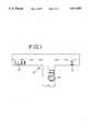
- FIG. 1is a schematic plan view of a traffic situation
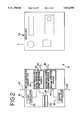
- FIG. 2is a block diagram of a traffic information warning system showing a combined transmitter and motion detector, and a receiver;
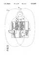
- FIG. 3is a diagrammatic representation showing the operation of the combined motion detector/transmitter.
- Traffic information warning systemsare used to convey messages regarding traffic situations. Two such traffic information warning systems are described in U.S. Pat. No. 5,497,148 and U.S. application Ser. No. 08/564,468, both of which are assigned to the assignee of the present invention and both of which are incorporated herein by reference.
- a traffic information warning systemgenerally designated by reference numeral 10 is used to convey a message regarding a traffic situation from a traffic advisory site, such as an emergency vehicle 12 or a roadside hazard 14, to a vehicle 16 as illustrated in FIG. 1.
- the system 10comprises a combined motion detector/transmitter 18 adapted for placement at the advisory site, such as inside the emergency vehicle 12 or alongside the roadside hazard 14.
- the system 10further comprises a receiver 20 adapted for placement inside the vehicle 16.
- the combined transmitter and motion detector of the present inventionis designed to meet these needs and to minimize the dangers a police officer may encounter while detaining a vehicle.
- the combined motion detector/transmitter 18includes a first oscillator 22 for transmitting a first carrier signal having a first carrier signal frequency S 1 and a second oscillator 24 for transmitting a second carrier signal having a second carrier signal frequency S 2 .
- unmodulated carrier signalsare used to transmit a message regarding a traffic situation either by the magnitude of the frequency difference between the first and second carrier signal frequencies S 1 , S 2 or the specific frequency locations of the carrier signals.
- the first and second carrier signalsare used to set up first and second disturbance fields D 1 , D 2 .
- the combined motion detector/transmitter 18indicates when a target T is moving through either of the disturbance fields. This is accomplished through use of first and second reflected signal receivers 26, 28 and first and second detector circuits 30, 32.
- the first oscillator 22transmits a first carrier signal at a first carrier signal frequency S 1 and sets up a first disturbance field D 1 .
- a target Tis within the first disturbance field D 1
- the first carrier signalis reflected by the target as a first reflected signal R 1 .
- the first reflected signal receiver 26picks up the first reflected signal R 1 and in conjunction with first detector circuit 30 determines the frequency and phase of the first reflected signal R 1 .
- the first reflected signal R 1will have a frequency and phase identical to the first carrier signal. However, if the target T is moving, the frequency of the first reflected signal R 1 will vary based upon the velocity of the target T and will vary in phase based upon the direction of movement of the target T.
- the first detector circuit 30is fed the frequency and phase of the first carrier signal. Thus, by comparing the first reflected signal R 1 to the first carrier signal, the first detector circuit 30 can determine the speed and direction of the target T.
- the frequency of the first reflected signalwill vary 72.2 Hertz per mile per hour.
- Second oscillator 24, second reflected signal receiver 28 and second detector circuit 32is similar to the operation of the first oscillator 22, first reflected signal receiver 26 and first detector circuit 30.
- the area covered by the combination of the fieldsis greater than by a single disturbance field.
- the other detector circuitassuming it is functioning properly, serves to cover for the nonfunctioning detector in those areas where the disturbance fields overlap.
- the first or second detector circuits 30, 32determine that the target T is moving within the first or second disturbance fields D 1 , D 2 . If the first or second detector circuits 30, 32 determine that the target T is moving within the first or second disturbance fields D 1 , D 2 , then the first or second detector circuits 30, 32 transmit a signal to an indicator 34 which indicates the detected presence of a moving target in either of the first or second disturbance fields D 1 , D 2 .
- the indicatorcan be either audio or visual, or both. If the indicator is of the audio type, the indicator could be a voice-synthesized message, for example.
- first oscillator antenna 36 and second oscillator antenna 38respectively cooperate with first and second oscillators 22, 24 to direct first and second carrier signals and to set up first and second disturbance fields D 1 , D 2 .
- First and second oscillator antennas 36, 38can take on various forms. It is preferred, however, that the first oscillator antenna 36 include a pair of patch antennas placed back-to-back. Similarly, back-to-back patch antennas are preferred for the second oscillator antenna 38. Using a pair of patch antennas placed back-to-back provides a nearly omnidirectional transmission of the carrier signals and hence, omnidirectional disturbance fields due to the well-known transmission characteristics of patch antennas.
- First receiver antenna 40which cooperates with first reflected signal receiver 26, and second receiver antenna 42, which cooperates with second reflected signal receiver 28, are used to receive first and second reflected signals R 1 , R 2 , respectively.
- These antennasmay also take on various forms. In the preferred embodiment, however, the first receiver antenna 40 and the second receiver antenna 42 are both patch antennas.
- the sensitivity of the detector circuits 30, 32is set so that the first detector circuit 30 does not confuse the first reflected signal R 1 with the second reflected signal R 2 and the second detector circuit 32 does not confuse the second reflected signal R 2 with the first reflected signal R 1 .
Landscapes
- Engineering & Computer Science (AREA)
- Radar, Positioning & Navigation (AREA)
- Remote Sensing (AREA)
- Physics & Mathematics (AREA)
- General Physics & Mathematics (AREA)
- Computer Security & Cryptography (AREA)
- Computer Networks & Wireless Communication (AREA)
- Business, Economics & Management (AREA)
- Emergency Management (AREA)
- Traffic Control Systems (AREA)
Abstract
Description
Claims (16)
Priority Applications (3)
| Application Number | Priority Date | Filing Date | Title |
|---|---|---|---|
| US08/618,855US5612685A (en) | 1996-03-20 | 1996-03-20 | Combined motion detector/transmitter for a traffic information warning system |
| PCT/US1997/003762WO1997035353A1 (en) | 1996-03-20 | 1997-03-11 | Combined motion detector/transmitter for a traffic information warning system |
| AU22032/97AAU2203297A (en) | 1996-03-20 | 1997-03-11 | Combined motion detector/transmitter for a traffic information warning system |
Applications Claiming Priority (1)
| Application Number | Priority Date | Filing Date | Title |
|---|---|---|---|
| US08/618,855US5612685A (en) | 1996-03-20 | 1996-03-20 | Combined motion detector/transmitter for a traffic information warning system |
Publications (1)
| Publication Number | Publication Date |
|---|---|
| US5612685Atrue US5612685A (en) | 1997-03-18 |
Family
ID=24479405
Family Applications (1)
| Application Number | Title | Priority Date | Filing Date |
|---|---|---|---|
| US08/618,855Expired - LifetimeUS5612685A (en) | 1996-03-20 | 1996-03-20 | Combined motion detector/transmitter for a traffic information warning system |
Country Status (3)
| Country | Link |
|---|---|
| US (1) | US5612685A (en) |
| AU (1) | AU2203297A (en) |
| WO (1) | WO1997035353A1 (en) |
Cited By (9)
| Publication number | Priority date | Publication date | Assignee | Title |
|---|---|---|---|---|
| WO1997035353A1 (en)* | 1996-03-20 | 1997-09-25 | Cobra Electronics Corp. | Combined motion detector/transmitter for a traffic information warning system |
| US6130607A (en)* | 1998-10-19 | 2000-10-10 | Eaton Corporation | Back-up protection sensor for a vehicle |
| US6367936B2 (en)* | 1998-06-04 | 2002-04-09 | Honda Giken Kogyo Kabushiki Kaisha | Road-curve mirror with radio wave reflection plate |
| US20030084599A1 (en)* | 2001-11-05 | 2003-05-08 | Rafael Elul | Restroom display systems |
| US20030102985A1 (en)* | 2001-11-30 | 2003-06-05 | Turbeville Terry A. | Emergency vehicle detection system |
| GB2489113A (en)* | 2012-03-21 | 2012-09-19 | Renesas Mobile Corp | A cellular based intelligent transportation system using a secondary cell carrier |
| US8581744B2 (en) | 2010-04-13 | 2013-11-12 | Lamar University | Traffic information warning systems and methods |
| US20140345396A1 (en)* | 2011-11-16 | 2014-11-27 | Airbus Operations Gmbh | Monitoring device and method for monitoring a movement profile of a user in the region of an actuating element of an aircraft or spacecraft |
| US8963738B2 (en) | 2010-04-13 | 2015-02-24 | Lamar University | Vehicle information systems and methods |
Citations (18)
| Publication number | Priority date | Publication date | Assignee | Title |
|---|---|---|---|---|
| US3673560A (en)* | 1970-05-21 | 1972-06-27 | Aerojet General Co | Vehicle alerting system |
| US3772641A (en)* | 1972-03-31 | 1973-11-13 | H Grosser | Self-testing emergency automotive warning system |
| US3784970A (en)* | 1971-02-17 | 1974-01-08 | W Simpkin | Emergency warning system with range control |
| US4196412A (en)* | 1978-01-16 | 1980-04-01 | General Signal Corporation | Driver alert system |
| US4216545A (en)* | 1977-06-15 | 1980-08-05 | Blaupunkt Werke Gmbh | Method and apparatus of communicating emergency signals from a transceiver in a transceiver communication network, particularly for citizen-band emergency use |
| US4358756A (en)* | 1979-06-26 | 1982-11-09 | Agence Centrale De Services (Acds) | Alarm transmission system |
| US4443790A (en)* | 1979-05-29 | 1984-04-17 | Bishop Frank A | Broadcast band siren alarm transmitter system for vehicles |
| US4454510A (en)* | 1978-12-18 | 1984-06-12 | Crow Robert P | Discrete address beacon, navigation and landing system (DABNLS) |
| US4529972A (en)* | 1982-04-21 | 1985-07-16 | Racal Security Limited | Signal transmitting and receiving arrangements |
| US4547778A (en)* | 1981-06-09 | 1985-10-15 | Texas Instruments Incorporated | Method and apparatus for automatic distress call signal transmission |
| US4794394A (en)* | 1987-09-08 | 1988-12-27 | Halstead Thomas L | Emergency vehicle proximity warning system |
| US4947151A (en)* | 1989-03-24 | 1990-08-07 | Rosenberger Jerome C | Wheel mounted motion and tampering alarm |
| US5091906A (en)* | 1989-12-18 | 1992-02-25 | Motorola, Inc. | Quasi-duplex radio system using bi-directional hole extension |
| US5210521A (en)* | 1990-07-26 | 1993-05-11 | Gary M. Hojell | Vehicle alarm apparatus and method for preventing injury to nearby persons |
| US5235329A (en)* | 1991-10-01 | 1993-08-10 | E A S Emergency Alert Systems, Inc. | Emergency vehicle detection device |
| US5307060A (en)* | 1992-03-17 | 1994-04-26 | Sy Prevulsky | Emergency vehicle alert system |
| US5493269A (en)* | 1991-09-20 | 1996-02-20 | C.A.R.E., Inc. | Vehicular safety sensor and warning system |
| US5497148A (en)* | 1994-08-30 | 1996-03-05 | Cobra Electronics Corporation | Traffic information warning system |
Family Cites Families (1)
| Publication number | Priority date | Publication date | Assignee | Title |
|---|---|---|---|---|
| US5612685A (en)* | 1996-03-20 | 1997-03-18 | Cobra Electronics Corp. | Combined motion detector/transmitter for a traffic information warning system |
- 1996
- 1996-03-20USUS08/618,855patent/US5612685A/ennot_activeExpired - Lifetime
- 1997
- 1997-03-11AUAU22032/97Apatent/AU2203297A/ennot_activeAbandoned
- 1997-03-11WOPCT/US1997/003762patent/WO1997035353A1/enactiveApplication Filing
Patent Citations (18)
| Publication number | Priority date | Publication date | Assignee | Title |
|---|---|---|---|---|
| US3673560A (en)* | 1970-05-21 | 1972-06-27 | Aerojet General Co | Vehicle alerting system |
| US3784970A (en)* | 1971-02-17 | 1974-01-08 | W Simpkin | Emergency warning system with range control |
| US3772641A (en)* | 1972-03-31 | 1973-11-13 | H Grosser | Self-testing emergency automotive warning system |
| US4216545A (en)* | 1977-06-15 | 1980-08-05 | Blaupunkt Werke Gmbh | Method and apparatus of communicating emergency signals from a transceiver in a transceiver communication network, particularly for citizen-band emergency use |
| US4196412A (en)* | 1978-01-16 | 1980-04-01 | General Signal Corporation | Driver alert system |
| US4454510A (en)* | 1978-12-18 | 1984-06-12 | Crow Robert P | Discrete address beacon, navigation and landing system (DABNLS) |
| US4443790A (en)* | 1979-05-29 | 1984-04-17 | Bishop Frank A | Broadcast band siren alarm transmitter system for vehicles |
| US4358756A (en)* | 1979-06-26 | 1982-11-09 | Agence Centrale De Services (Acds) | Alarm transmission system |
| US4547778A (en)* | 1981-06-09 | 1985-10-15 | Texas Instruments Incorporated | Method and apparatus for automatic distress call signal transmission |
| US4529972A (en)* | 1982-04-21 | 1985-07-16 | Racal Security Limited | Signal transmitting and receiving arrangements |
| US4794394A (en)* | 1987-09-08 | 1988-12-27 | Halstead Thomas L | Emergency vehicle proximity warning system |
| US4947151A (en)* | 1989-03-24 | 1990-08-07 | Rosenberger Jerome C | Wheel mounted motion and tampering alarm |
| US5091906A (en)* | 1989-12-18 | 1992-02-25 | Motorola, Inc. | Quasi-duplex radio system using bi-directional hole extension |
| US5210521A (en)* | 1990-07-26 | 1993-05-11 | Gary M. Hojell | Vehicle alarm apparatus and method for preventing injury to nearby persons |
| US5493269A (en)* | 1991-09-20 | 1996-02-20 | C.A.R.E., Inc. | Vehicular safety sensor and warning system |
| US5235329A (en)* | 1991-10-01 | 1993-08-10 | E A S Emergency Alert Systems, Inc. | Emergency vehicle detection device |
| US5307060A (en)* | 1992-03-17 | 1994-04-26 | Sy Prevulsky | Emergency vehicle alert system |
| US5497148A (en)* | 1994-08-30 | 1996-03-05 | Cobra Electronics Corporation | Traffic information warning system |
Cited By (13)
| Publication number | Priority date | Publication date | Assignee | Title |
|---|---|---|---|---|
| WO1997035353A1 (en)* | 1996-03-20 | 1997-09-25 | Cobra Electronics Corp. | Combined motion detector/transmitter for a traffic information warning system |
| US6367936B2 (en)* | 1998-06-04 | 2002-04-09 | Honda Giken Kogyo Kabushiki Kaisha | Road-curve mirror with radio wave reflection plate |
| US6130607A (en)* | 1998-10-19 | 2000-10-10 | Eaton Corporation | Back-up protection sensor for a vehicle |
| US20030084599A1 (en)* | 2001-11-05 | 2003-05-08 | Rafael Elul | Restroom display systems |
| US6778101B2 (en)* | 2001-11-30 | 2004-08-17 | Terry A. Turbeville | Emergency vehicle detection system |
| WO2003049061A1 (en)* | 2001-11-30 | 2003-06-12 | Turbeville Terry A | Emergency vehicle detection system |
| US20030102985A1 (en)* | 2001-11-30 | 2003-06-05 | Turbeville Terry A. | Emergency vehicle detection system |
| US8581744B2 (en) | 2010-04-13 | 2013-11-12 | Lamar University | Traffic information warning systems and methods |
| US8963738B2 (en) | 2010-04-13 | 2015-02-24 | Lamar University | Vehicle information systems and methods |
| US20140345396A1 (en)* | 2011-11-16 | 2014-11-27 | Airbus Operations Gmbh | Monitoring device and method for monitoring a movement profile of a user in the region of an actuating element of an aircraft or spacecraft |
| US9720011B2 (en)* | 2011-11-16 | 2017-08-01 | Airbus Operations Gmbh | Monitoring device and method for monitoring a movement profile of a user in the region of an actuating element of an aircraft or spacecraft |
| GB2489113A (en)* | 2012-03-21 | 2012-09-19 | Renesas Mobile Corp | A cellular based intelligent transportation system using a secondary cell carrier |
| GB2489113B (en)* | 2012-03-21 | 2013-12-18 | Renesas Mobile Corp | Method and apparatus for dynamic vehicular communications |
Also Published As
| Publication number | Publication date |
|---|---|
| WO1997035353A1 (en) | 1997-09-25 |
| AU2203297A (en) | 1997-10-10 |
Similar Documents
| Publication | Publication Date | Title |
|---|---|---|
| US5554982A (en) | Wireless train proximity alert system | |
| US5497148A (en) | Traffic information warning system | |
| US5699986A (en) | Railway crossing collision avoidance system | |
| US6384776B1 (en) | EM signal detection and position broadcasting system and method | |
| USRE38763E1 (en) | Emergency vehicle warning system and method | |
| US6615137B2 (en) | Method and apparatus for transferring information between vehicles | |
| US7099774B2 (en) | GPS based vehicle warning and location system | |
| US5594432A (en) | Traffic information warning system | |
| US6472978B1 (en) | Traffic system to prevent from accidents | |
| US7113108B1 (en) | Emergency vehicle control system traffic loop preemption | |
| US6236336B1 (en) | Traffic information warning system with single modulated carrier | |
| CA2292280A1 (en) | Method and apparatus for remote location, identification and/or control of motor vehicles | |
| US5612685A (en) | Combined motion detector/transmitter for a traffic information warning system | |
| JPH07105500A (en) | Intersection warning system | |
| JPH05508948A (en) | Warning system for road accident prevention | |
| RU2540816C1 (en) | System to ensure traffic safety for carriers and pedestrians | |
| SI9300634A (en) | Safety preventive method and coresponding device | |
| Najm et al. | Analysis of crossing path crash countermeasure systems | |
| EP0992965B1 (en) | Highway driving assistance system for car drivers | |
| US5052048A (en) | Crime deterrent system | |
| JPH0245264A (en) | Road condition monitoring device | |
| WO1998015845A1 (en) | Automatic collision notification | |
| JPH11110688A (en) | Traffic safety device and traffic safety system | |
| US3101394A (en) | Highway informer keying system | |
| TR2024000807U5 (en) | EMERGENCY WARNING SYSTEM FOR ROAD VEHICLES |
Legal Events
| Date | Code | Title | Description |
|---|---|---|---|
| AS | Assignment | Owner name:COBRA ELECTRONICS CORP., ILLINOIS Free format text:ASSIGNMENT OF ASSIGNORS INTEREST;ASSIGNOR:OLIVA, DAVID C.;REEL/FRAME:008027/0875 Effective date:19960315 | |
| STCF | Information on status: patent grant | Free format text:PATENTED CASE | |
| FEPP | Fee payment procedure | Free format text:PAYOR NUMBER ASSIGNED (ORIGINAL EVENT CODE: ASPN); ENTITY STATUS OF PATENT OWNER: SMALL ENTITY | |
| FPAY | Fee payment | Year of fee payment:4 | |
| AS | Assignment | Owner name:LASALLE BANK NATIONAL ASSOCIATION, ILLINOIS Free format text:SECURITY AGREEMENT;ASSIGNOR:COBRA ELECTRONICS CORPORATION;REEL/FRAME:012551/0547 Effective date:20020131 | |
| FPAY | Fee payment | Year of fee payment:8 | |
| AS | Assignment | Owner name:COBRA ELECTRONICS CORPORATION, ILLINOIS Free format text:RELEASE BY SECURED PARTY;ASSIGNOR:LASALLE BANK NATIONAL ASSOCIATION;REEL/FRAME:020808/0694 Effective date:20080215 | |
| AS | Assignment | Owner name:THE PRIVATEBANK AND TRUST COMPANY, ILLINOIS Free format text:SECURITY AGREEMENT;ASSIGNOR:COBRA ELECTRONICS CORPORATION;REEL/FRAME:021523/0748 Effective date:20080215 | |
| FPAY | Fee payment | Year of fee payment:12 | |
| AS | Assignment | Owner name:HARRIS N.A., AS ADMINISTRATIVE AGENT, ILLINOIS Free format text:SECURITY AGREEMENT;ASSIGNOR:COBRA ELECTRONICS CORPORATION;REEL/FRAME:025105/0015 Effective date:20100716 | |
| AS | Assignment | Owner name:COBRA ELECTRONICS CORPORATION, ILLINOIS Free format text:RELEASE BY SECURED PARTY;ASSIGNOR:THE PRIVATEBANK AND TRUST COMPANY;REEL/FRAME:025105/0746 Effective date:20100716 | |
| AS | Assignment | Owner name:COBRA ELECTRONICS CORPORATION, ILLINOIS Free format text:RELEASE BY SECURED PARTY;ASSIGNOR:BMO HARRIS BANK N.A.;REEL/FRAME:033925/0334 Effective date:20141008 | |
| AS | Assignment | Owner name:ASPEN FINCO, LLC, NEW YORK Free format text:SECURITY INTEREST;ASSIGNORS:VENOM ELECTRONICS HOLDINGS, INC.;COBRA ELECTRONICS CORPORATION;REEL/FRAME:033946/0769 Effective date:20141014 | |
| AS | Assignment | Owner name:ASPEN FINCO, LLC, NEW YORK Free format text:SECURITY INTEREST;ASSIGNORS:VENOM ELECTRONICS CORPORATION;COBRA ELECTRONICS CORPORATION;REEL/FRAME:033957/0426 Effective date:20141008 | |
| AS | Assignment | Owner name:WELLS FARGO BANK, NATIONAL ASSOCIATION, PENNSYLVAN Free format text:SECURITY INTEREST;ASSIGNOR:COBRA ELECTRONICS CORPORATION;REEL/FRAME:033968/0393 Effective date:20141017 | |
| AS | Assignment | Owner name:ASPEN FINCO, LLC, NEW YORK Free format text:CORRECTIVE ASSIGNMENT TO CORRECT THE DATE OF THE ASSIGNMENT PREVIOUSLY RECORDED ON REEL 033946 FRAME 0769. ASSIGNOR(S) HEREBY CONFIRMS THE ASSIGNMENT. THIS ASSIGNMENT DATED 10/17/14 REPLACES IN ITS ENTIRETY THE ASSIGNMENT DATED 10/14/14 RECORDED AT R/F 033946/0769.;ASSIGNORS:VENOM ELECTRONICS HOLDINGS, INC.;COBRA ELECTRONICS CORPORATION;REEL/FRAME:034056/0859 Effective date:20141017 | |
| AS | Assignment | Owner name:LBC CREDIT PARTNERS III, L.P., AS AGENT, PENNSYLVA Free format text:SECURITY INTEREST;ASSIGNOR:COBRA ELECTRONICS CORPORATION;REEL/FRAME:035992/0497 Effective date:20150626 | |
| AS | Assignment | Owner name:CAPITALSOUTH PARTNERS SBIC FUND III, L.P., AS AGEN Free format text:SECURITY INTEREST;ASSIGNOR:COBRA ELECTRONICS CORPORATION;REEL/FRAME:035998/0779 Effective date:20150626 Owner name:COBRA ELECTRONICS CORPORATION, ILLINOIS Free format text:RELEASE BY SECURED PARTY;ASSIGNOR:WELLS FARGO BANK, NATIONAL ASSOCIATION, AS AGENT;REEL/FRAME:035988/0051 Effective date:20150626 Owner name:VENOM ELECTRONICS HOLDINGS, INC., ILLINOIS Free format text:RELEASE BY SECURED PARTY;ASSIGNOR:WELLS FARGO BANK, NATIONAL ASSOCIATION, AS AGENT;REEL/FRAME:035988/0051 Effective date:20150626 | |
| AS | Assignment | Owner name:VENOM ELECTRONICS HOLDINGS, INC., ILLINOIS Free format text:RELEASE BY SECURED PARTY;ASSIGNOR:ASPEN FINCO, LLC, AS AGENT;REEL/FRAME:035976/0227 Effective date:20150626 Owner name:COBRA ELECTRONICS CORPORATION, ILLINOIS Free format text:RELEASE BY SECURED PARTY;ASSIGNOR:ASPEN FINCO, LLC, AS AGENT;REEL/FRAME:035976/0227 Effective date:20150626 | |
| AS | Assignment | Owner name:COBRA ELECTRONICS CORPORATION, ILLINOIS Free format text:RELEASE BY SECURED PARTY;ASSIGNOR:CAPITALSOUTH PARTNERS SBIC FUND III, L.P., AS AGENT;REEL/FRAME:045852/0861 Effective date:20180402 |