US5611746A - Vehicle drivetrain coupling - Google Patents
Vehicle drivetrain couplingDownload PDFInfo
- Publication number
- US5611746A US5611746AUS08/496,250US49625095AUS5611746AUS 5611746 AUS5611746 AUS 5611746AUS 49625095 AUS49625095 AUS 49625095AUS 5611746 AUS5611746 AUS 5611746A
- Authority
- US
- United States
- Prior art keywords
- casing
- rotary members
- coupling
- pair
- clutch
- Prior art date
- Legal status (The legal status is an assumption and is not a legal conclusion. Google has not performed a legal analysis and makes no representation as to the accuracy of the status listed.)
- Expired - Lifetime
Links
Images


Classifications
- F—MECHANICAL ENGINEERING; LIGHTING; HEATING; WEAPONS; BLASTING
- F16—ENGINEERING ELEMENTS AND UNITS; GENERAL MEASURES FOR PRODUCING AND MAINTAINING EFFECTIVE FUNCTIONING OF MACHINES OR INSTALLATIONS; THERMAL INSULATION IN GENERAL
- F16H—GEARING
- F16H48/00—Differential gearings
- F16H48/20—Arrangements for suppressing or influencing the differential action, e.g. locking devices
- F16H48/22—Arrangements for suppressing or influencing the differential action, e.g. locking devices using friction clutches or brakes
- B—PERFORMING OPERATIONS; TRANSPORTING
- B60—VEHICLES IN GENERAL
- B60K—ARRANGEMENT OR MOUNTING OF PROPULSION UNITS OR OF TRANSMISSIONS IN VEHICLES; ARRANGEMENT OR MOUNTING OF PLURAL DIVERSE PRIME-MOVERS IN VEHICLES; AUXILIARY DRIVES FOR VEHICLES; INSTRUMENTATION OR DASHBOARDS FOR VEHICLES; ARRANGEMENTS IN CONNECTION WITH COOLING, AIR INTAKE, GAS EXHAUST OR FUEL SUPPLY OF PROPULSION UNITS IN VEHICLES
- B60K17/00—Arrangement or mounting of transmissions in vehicles
- B60K17/04—Arrangement or mounting of transmissions in vehicles characterised by arrangement, location or kind of gearing
- B60K17/16—Arrangement or mounting of transmissions in vehicles characterised by arrangement, location or kind of gearing of differential gearing
- B60K17/20—Arrangement or mounting of transmissions in vehicles characterised by arrangement, location or kind of gearing of differential gearing in which the differential movement is limited
- F—MECHANICAL ENGINEERING; LIGHTING; HEATING; WEAPONS; BLASTING
- F16—ENGINEERING ELEMENTS AND UNITS; GENERAL MEASURES FOR PRODUCING AND MAINTAINING EFFECTIVE FUNCTIONING OF MACHINES OR INSTALLATIONS; THERMAL INSULATION IN GENERAL
- F16H—GEARING
- F16H48/00—Differential gearings
- F16H48/06—Differential gearings with gears having orbital motion
- F16H48/08—Differential gearings with gears having orbital motion comprising bevel gears
Definitions
- This inventionrelates to a coupling for use with a vehicle drivetrain to rotatively couple a pair of rotary members about a rotational axis.
- Hydraulic couplingshave previously utilized hydraulic pumps to couple rotary members of a vehicle drivetrain.
- U.S. Pat. No. 4,012,968 Kelbeldiscloses a differential mechanism wherein a hydraulic pump of the gerotor type is located radially outward from the axis of rotation of the two members and provides pumped hydraulic fluid to a clutch that controls operation of a bevel type planetary gear set to limit the differential action so as to thus have a limited slip function.
- U.S. Pat. No. 4,730,514 Shikata et aldiscloses another differential mechanism wherein a hydraulic pump controls operation of a bevel gear type planetary gear set that extends between two rotary members such that a limited slip function of the differential gear operation is also provided.
- United States Patent Okcuoglu et aldiscloses a vehicle drivetrain hydraulic coupling having a hydraulic clutch of the gerotor type. Furthermore, U.S. Pat. Nos. 3,748,928 Shiber; 4,719,998 Hiramatsu et al; 4,719,998 Hiramatsu et al; 4,727,966 Hiramatsu et al; and 4,909,371 Okamoto et al disclose hydraulic pumps utilized within vehicle drivetrains to control actuation of a clutch that connects two rotary members of a vehicle drivetrain.
- An object of the present inventionis to provide an improved coupling for use with a vehicle drivetrain to rotatively couple a pair of rotary members about a rotational axis.
- the vehicle drivetrain coupling of the inventionhas a bevel type planetary gear set and includes a lock for selectively preventing the extent of torque transferred from a coupling casing through the planetary gear set to a pair of rotary members from affecting actuation of a clutch that couples the rotary members.
- the lockincludes a thrust plate and a lock member that is selectively movable between an unlocked position where the planetary gear set can actuate the clutch according to the level of torque transmitted and a locked position where such actuation is prevented.
- the lockhas particular utility when utilized with a coupling having a hydraulic pump that actuates the clutch and also functions as a brake in coupling the pair of rotary members to each other.
- the couplingincludes a pump and has an adjuster for adjusting the resistance of fluid flow from a hydraulic pump that operates in response to differential rotation between the two rotary members.
- This adjusterin a supercharged embodiment of the coupling has adjustable valves for controlling the cross-sectional flow area at both a transfer port through which pumped hydraulic fluid is fed to a chamber and an outlet port that further controls pumped hydraulic fluid flow from the chamber back to the pump.
- the adjusterhas an adjustable valve at only the transfer port.
- the adjusterhas particular utility when utilized with a coupling having a clutch that is actuated by the pumped hydraulic fluid to couple the two rotary members to each other and especially when the coupling also has a planetary gear set that cooperates in coupling the two rotary members to each other.
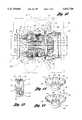
- FIG. 1is a sectional view taken through one embodiment of a coupling constructed in accordance with the present invention to couple a pair of rotary members and is illustrated as having a hydraulic pump that operates in a supercharged manner and has an associated clutch for limiting differential operation of a bevel type planetary gear set;
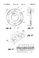
- FIG. 2is a sectional view taken through the coupling along the direction of line 2--2 in FIG. 1 and discloses the pump as having an impeller with six teeth meshed with an internal ring gear having seven teeth to provide a pumping action that allows the pump to function as a brake while still having relatively constant pumping pressure that facilitates actuation of the associated clutch without fluid pressure pulsation;
- FIG. 3is a view similar to FIG. 2 to illustrate that the pump can also have its impeller provided with five teeth and its internal ring gear provided with six teeth when a greater pumping capacity is desired;
- FIG. 4is a view similar to FIGS. 2 and 3 but illustrating the impeller as having seven teeth and the internal ring gear as having eight teeth when a more constant fluid pressure is desired;
- FIG. 5an exploded perspective view illustrating the construction of inlet valves for inlet ports through which hydraulic fluid is pumped into a casing of the coupling;
- FIG. 6is a sectional view taken along the direction of line 6--6 in FIG. 5 to illustrate the opening and closing valve operation
- FIG. 7is a partial view of FIG. 1 but taken on an enlarged scale and illustrating a lock for selectively preventing the level of torque carried by the bevel type planetary gear set of the coupling from affecting actuation of the clutch of the coupling;
- FIG. 8is a partial view of FIG. 1 but taken on an enlarged scale and illustrating the construction of an adjuster valve for a transfer port of the coupling;
- FIG. 9is a partial view of FIG. 1 but taken on an enlarged scale and illustrating the construction of an adjuster valve for an outlet port of the coupling;
- FIG. 10is a partial sectional view taken along the direction of arrows 10--10 in FIG. 9 to illustrate the construction of the control valve at the outlet port with a valve element thereof shown in a solid line indicated open position and a phantom line indicated closed position with respect to the outlet port;
- FIG. 11is a perspective view that further illustrates the construction of the outlet port and the associated valve
- FIG. 12is a sectional view of another embodiment of the coupling that is similar to the embodiment of FIG. 1 but, instead of having a pump that operates in a supercharged manner, has its outlet port extending through a clutch actuating piston of the coupling;
- FIG. 13is an enlarged sectional view illustrating the transfer port and associated check valve through which the hydraulic fluid is pumped to the clutch actuating piston of each embodiment of the coupling;
- FIG. 14is a partial perspective view that further illustrates the transfer port check valve in its closed position
- FIG. 15is a partial perspective view similar to FIG. 14 but with the transfer port check valve shown in its open position;
- FIG. 16is an axial view of one construction of an actuating piston of the clutch
- FIG. 17is a sectional view of the actuating piston taken along the direction of line 17--17 in FIG. 16;
- FIG. 18is a perspective view illustrating the piston mounted control valve outlet port which includes a main passage and a bleed passage and which is located within a recess;
- FIG. 19is a sectional view taken through the control valve generally in the direction of line 19--19 in FIG. 18 and also illustrates the valve element that controls fluid flow through the port illustrated;
- FIG. 20is a partial perspective view of another construction of the control valve element for defining the bleed passage.
- FIG. 21is a schematic view that illustrates the fluid flow of the supercharged circuit of the coupling embodiment of FIG. 1.
- a partially illustrated vehicle drivetrainthat is generally indicated by 20 includes a differential 22 that is rotatively driven from the vehicle engine by a rotary drive member 24 and operates to drive a pair of axial half shafts 26 and 28 that respectively embody a pair of rotary members which rotate about a rotational axis A.
- the differentialincludes a housing 30 for containing hydraulic fluid and having suitable unshown seals through which the rotary members 24, 26 and 28 project.
- the differentialincludes a coupling 32 that embodies the present invention and operates to rotatively couple the axial half shafts 26 and 28 driven by the rotary drive member 24 as is hereinafter more fully described.
- the hydraulic coupling 32includes a casing 34 of a hollow construction that is rotatable within the housing about the rotational axis A and connected to the pair of rotary members 26 and 28 by a bevel type planetary gear set 36 as is hereinafter more fully described.
- Casing 34 as illustratedincludes a somewhat cup-shaped member 38 and a cap member 40 which each have peripheral flanges secured to each other by circumferentially spaced bolts 42.
- Another set of circumferentially spaced bolts 43secures a bevel type ring gear 44 to the cup-shaped casing member 38 for rotational driving of the casing 34 about axis A by the drive member 24.
- a pair of antifriction bearing assemblies 45a and 45brespectively mount the casing cap member 40 and the ring gear 44 secured to the casing cup-shaped member 38 to cooperatively support casing 34 for rotation within the differential housing about axis A.
- a ring seal assembly 46extends between the housing and the cap member 40 of the casing.
- the coupling 32also includes a hydraulic pump 48 located within the casing 34 along the rotational axis A and including a pumping component embodied by an impeller 50 having external teeth 52.
- the hydraulic pumpalso includes an internal ring gear 54 mounted by the casing 34 for rotation eccentrically with respect to the toothed impeller 50 and including internal teeth 56 of a number that is one more than the impeller teeth and which are in a meshing relationship with the impeller teeth to provide a pumping action upon relative rotation between the casing and the toothed impeller.
- the impeller 50most preferably has six teeth 52 and the internal ring gear 54 has seven teeth 56 which is a relationship that provides sufficient pumping capacity so that the hydraulic pump can act effectively as a brake while still having relatively constant pumping pressure without fluid pulsation that would adversely affect the hydraulic coupling provided between the rotary members.
- the hydraulic pump 48'it is also possible for the hydraulic pump 48' to have its impeller 50' provided with five external teeth 52' and for the ring gear 54' to have six teeth 56' meshed with the impeller teeth which is a construction that will provide a somewhat greater pumping capacity but less consistency in the fluid pressure, but not so inconsistent as to interfere with effective hydraulic coupling between the rotary members.
- FIG. 3it is also possible for the hydraulic pump 48' to have its impeller 50' provided with five external teeth 52' and for the ring gear 54' to have six teeth 56' meshed with the impeller teeth which is a construction that will provide a somewhat greater pumping capacity but less consistency in the fluid pressure, but not so inconsistent as to interfere with effective hydraulic coupling between
- the hydraulic pump 48"it is also possible for the hydraulic pump 48" to have its impeller 50" provided with seven internal teeth 52" and its internal ring gear 54" to have eight teeth 56" when more consistent fluid pressure is desirable even though there is an accompanying decrease in the amount of pumped fluid.
- the impellerhas between five and seven external teeth with six being most preferable while the internal ring gear has one more tooth than the number of impeller teeth utilized.
- each of the inlets 58includes an associated check valve 60 for opening and closing inlet bores 62 (FIG. 5) of varying size along the direction of rotation.
- Each check valve 60 as shown in FIGS. 5 and 6has a thin valve element 64 that is mounted by guides such as the threaded bolts 66 shown for movement between the solid line indicated open position of FIG. 6 and the phantom line indicated closed position.
- one of the check valves 60opens to permit the hydraulic fluid to be pumped from the housing 30 into the casing 34 while the other check valve 60 is then closed so that the hydraulic fluid is not pumped out of the casing through the other inlet port.
- the open and closed positions of the inlet ports 58is reversed.
- a clutch 68is received within the cup-shaped member 38 of casing 34. Adjacent the junction of the casing cup-shaped member 38 with the casing cap member 40, a pump housing insert 70 is mounted and receives the hydraulic pump 48 as well as interfacing with the clutch 68.
- This insert 70has an annular piston chamber 71 that receives a clutch actuating piston 72 that engages the clutch 68 as is hereinafter more fully described to couple the casing 34 with the left axle half shaft 28 and also with the right axle half shaft 26 as is also hereinafter more fully described.
- Insert 70also has a wall defining a pair of transfer ports 74 (FIG. 21) through which hydraulic fluid is pumped from the hydraulic pump 48 to the piston chamber to act on the clutch actuating piston.
- This flow through the transfer ports 74is through one of the transfer ports upon one direction of relative rotation between the impeller 52 and the ring gear 54 and is through the other transfer port during the other direction of relative rotation between the impeller and the ring gear.
- Each of the transfer ports 74has an associated check valve 76 of a construction that is hereinafter more fully described in connection with FIGS. 13 through 15. These check valves 76 ensure that the hydraulic fluid pumped through either transfer port to the clutch actuating piston is not pumped back into the hydraulic pump 48 through the other transfer port.
- an outlet port 78is also provided and in the embodiment of FIG. 1 is located on the pump housing insert 70 such that the pumped fluid flows from the piston chamber 71 back to the low pressure side of the pump in a supercharged manner.
- a control valve 80 associated with each outlet port 78closes the outlet port as is hereinafter more fully described when the pumped fluid reaches a predetermined pressure which is proportional to the rate of rotation between the pump impeller and ring gear and thus corresponds to the relative rotation between the right axle half shaft 26 connected through the differential 36 to the casing 34 and the left axle half shaft 28 that is connected to the impeller 50.
- the valve 80closes as is hereinafter more fully described to close the outlet port 78 and thus prevent the hydraulic fluid from being pumped from the hydraulic pump 48. This causes the hydraulic pump 48 to act as a brake by coupling the impeller 52 with the internal ring gear 54 and thereby also couples the rotary members embodied by the right and left axle half shafts 26 and 28 to each other.
- control valve 80includes an elongated metallic strip valve element 82 having one end 84 that is mounted in a spaced relationship to the outlet port 78 in any suitable manner such as by the headed bolts 86 illustrated.
- Valve element 82also has another distal end 88 that is movable between a solid line indicated open position spaced from the outlet port 78 as shown in FIG. 10 and a phantom line indicated closed position that closes the outlet port.
- This valve element 82is of the bimetallic type and thus includes two metals 90 and 92 that have different coefficients of thermal expansion so as to cause the valve element to move as its temperature is raised and lowered.
- valve element end 88moves toward the outlet port 78 with the net result being that the less viscous fluid will close the valve 80 at the same pressure of pumped fluid corresponding to the same amount of relative rotation between the axle half shafts. Furthermore, upon cooling of the hydraulic fluid such as after rest for a certain period of time, the valve element end 88 moves away from the outlet port 78 such that the valve closes at the same pressure of pumping of the more viscous hydraulic fluid.
- the bimetallic valve element 82compensates for viscosity changes as the hydraulic fluid is heated and cooled to ensure that the coupling between the two rotary members embodied by the two axle half shafts takes place at the same rate of relative rotation.
- valve closingcauses the hydraulic pump 48 to then function as a brake that limits the relative rotation between the two rotary members embodied by the two axle half shafts and also causes the actuation of the clutch 68 to further couple the two axle half shafts to each other.
- the outlet port 78preferably includes a main passage 94 that is closed by the valve element 82 as its end 88 moves from the open position to the closed position as previously described.
- Outlet port 78also includes a bleed passage 96 that remains open even when the valve element 82 is closed with respect to the main passage 94. This bleed passage 94 dampens the closing action of the control valve element 82 and also allows fluid flow that, upon termination of the torque loading between the two rotary members, releases the fluid pressure in the piston chamber to permit opening of the control valve 80.
- valve element 82When the valve element 82 opens, the fluid flow through both passages of the outlet port 78 provides cleaning of the bleed passage 96 to remove any small particles that might block the smaller cross-sectional flow area of the bleed passage.
- the control valve 80is thus self cleaning during normal usage. Also, as the bleed passage 96 allows valve opening and pressurized fluid to flow from the piston chamber 71 when the hydraulic pumping stops as the pair of rotary members are unloaded, the clutch 68 is disengaged as the pressure in the piston chamber drops as is hereinafter more fully described.
- the couplingincludes an elongated mounting recess 98 having one end 100 at which the one end 84 of the valve element 82 is mounted and having another end 102 at which the main passage 94 and bleed passage 96 of the outlet port 78 are located.
- This recessin cooperation with the bimetallic valve element 82 provides a continually varying change in the cross-sectional flow area of flow to the outlet port 78 from the other side of the valve element such that movement of the valve element end 88 in response to temperature changes provides an accurate control of the pressure at which the valve element closes to initiate the operation of the hydraulic pump as a brake and the actuation of the clutch.
- valve element 82For any given predetermined open position of the valve element 82, there is a certain pressure at which the hydraulic fluid of a certain velocity will cause closure of the valve element. This results from the flow of the hydraulic fluid between the valve element end 88 and the adjacent end of the recess 102 to the outlet port 78. This flow causes a pressure drop in the fluid upon passage past the valve element end 88 so that there is less force acting on the outlet side of the valve element end 88 than on the hydraulic pump side which are respectively the lower and upper sides as illustrated in FIG. 10.
- Movement of the valve element 82 to change the position of its end 88 in response to temperature changesvaries the cross-sectional area of flow between this valve element end and the recess end 102 so as to thereby accurately compensate for temperature changes and ensure that the closure of the valve 80 corresponds to the same rate of relative rotation between the rotary members embodied by the axle half shafts 26 and 28 shown in FIG. 1.
- the coupling 32whose one rotary member embodied by the right axle half shaft 26 is connected with the casing 34 also has the clutch 68 previously described that extends between the other rotary member embodied by the other axle half shaft 28 and the casing.
- This clutch 68 as shown in FIG. 7includes alternating sets of clutch plates 112 and 114 with the one set of clutch plates 112 having outer peripheries with spline connections 116 to the casing 34, and with the other set of clutch plates 114 having a central opening with spline connections 117 to a hub 118 that has spline connections 119 to the planetary gear set 36 as is hereinafter more fully described.
- the left axle half shaft 28has a spline connection 120 to the planetary gear set 36 as shown in FIG. 7 and a spline connection 121 to the pump impeller 50 as shown in FIG. 1 on the opposite side of the insert 70 from the clutch 68.
- Pumped hydraulic fluid acting on the clutch piston 72compresses the sets of clutch plates 112 and 114 to provide the coupling between the pair of rotary members embodied by the axle half shafts 26 and 28.
- the hydraulic coupling 32 illustrated in FIG. 1has the planetary gear set 36 which is of the bevel gear type connecting the casing 34 and the one rotary member embodied by the right axle half shaft 26.
- This planetary gear set 36includes a pair of bevel side gears 124 and 126 which have respective spline connections 128 and 120 to the rotary members embodied by the axle half shafts 26 and 28.
- Bevel planet gears 132 of the gear set 36are each meshed with the pair of bevel side gears 124 and 126 and are rotatably supported by a cross pin 134 that extends through the rotational axis A between opposite sides of the casing 34.
- the clutch 68is connected as shown in FIG.
- Planetary gear set 36provides a differential action between the rotary members embodied by the axle half shafts 26 and 28 until closure of the control valve 80 causes the hydraulic pump 48 to function as a brake and also actuate the clutch 68 as previously described whereupon the axle half shaft 26 is coupled through the spline connections 128, bevel side gear 124, planet gears 132, bevel side gear 126 and the spline connection 120 with the other axle half shaft 28.
- FIG. 12another embodiment of the coupling is indicated by reference numeral 32a.
- This embodiment of the hydraulic coupling 32ahas the same construction as the embodiment disclosed in FIGS. 1-11 except as will be noted and thus has like reference numerals applied to like components thereof such that much of the previous description is applicable and thus need not be repeated.
- the outlet port 78extends through the piston 72 within the piston chamber 71.
- the control valve 80which has the same construction as previously described is mounted on the piston 72 that actuates the clutch. Fluid that flows through the control valve 80 prior to its closing and the bleed fluid that flows therethrough lubricates the clutch 68 in this embodiment.
- this embodimentunlike the previously described embodiment of the coupling does not operate in a supercharged manner with the pumped fluid from the piston chamber 71 being fed back to the low pressure side of the pump.
- this embodiment of the coupling 32adoes have a pair of the transfer ports 74 so as to operate in both directions of relative rotation between the rotary members embodied by the axle half shafts, but only one outlet portion is needed for effective operation.
- each transfer port 74extends through the insert 70 from the pump side toward the piston side and has the associated check valve 76 mounted on the piston side where the piston is sealed between inner and outer annular flanges 142 and 144 by respective O-rings 146 and 148.
- the transfer port 74On the pump side, the transfer port 74 has an enlarged shallow collection portion 150 that allows the pumped hydraulic fluid to be received from different radial locations for eventual flow through the transfer port and the check valve 76 in the piston side in order to provide the piston actuation as previously described. As best illustrated in FIGS.
- each check valve 76includes a metallic strip valve element 152 having one end 154 mounted on the metallic insert by suitable fasteners 156 such as the headed bolts shown and has another distal end 158 that is normally biased to the closed position of FIG. 14 by a resilient spring force of the valve element.
- the pressurized fluid upon pumpingacts against the spring bias to provide opening of the valve distal end 158 as shown in FIG. 15 to permit the fluid flow that moves the piston and actuates the clutch as previously described.
- An adjustment capability of the cross-sectional flow area through each transfer port 74 and outlet port 78 of the FIG. 1 embodiment, and of each transfer port 74 of the FIG. 12 embodiment, as is hereinafter more fully described,allows these ports to be tuned from a normal relationship where the flow areas are approximately equal to each other. Tuning of the coupling can also be performed so the cross-sectional flow area of the transfer port 74 is smaller than the cross-sectional flow area of the outlet port 78 such that the closing of the open control valve 80 is delayed as is the consequent actuation of the clutch 68. Furthermore, faster control valve closing and consequent clutch actuation can be achieved by adjusting the cross-sectional flow area of the transfer port 74 to be larger than the cross-sectional flow area of the open control valve 80. In addition, it may also be possible to tune the operation by controlling the closing spring bias of the transfer port valve element 152.
- FIGS. 16 and 17another embodiment of the piston 72 of the FIG. 12 embodiment of the coupling is illustrated as having the control valve 80 mounted thereon as previously described and also is shown as having a coating 160 of an elastomeric rubber-like material, such as for example an ethylene acrylic resin, on its one side which faces the hydraulic pump in the assembled condition.
- This coating 160also defines outer and inner annular seals 162 and 163 for sealing with the adjacent outer and inner annular walls of the coupling to provide a slidably sealed relationship.
- This coating 160is injection molded on a stamped steel plate 164 of the piston 72 and also has positioning lugs 166 spaced circumferentially about its periphery so as to protect the seal 162 when the piston moves to its full extent toward the left within the casing of the coupling.
- the piston coating 160is injection molded to define the outlet port 78 with its main passage 94 and bleed passage 96 previously described as well as to define the mounting recess 98 in which the valve element 82 of the control valve 80 is mounted as specifically shown in FIG. 19. Injection molding of the coating facilitates the provision of the outlet port 78 with its main passage 94 and bleed passage 96.
- the coating 160may have an annular portion 168 that extends through a hole in the piston plate 164 to readily define the required cross-sectional flow area of the main passage 94 of the outlet port 78 to thereby also facilitate tuning of the coupling as described above.
- the bleed passage 96' of the outlet portmay be provided by forming the distal end of the control valve element 82 as illustrated. Upon opening of the control valve element 82, cleaning flow of the bleed passage takes place in the same manner previously described where the bleed passage is located on either the pump insert 70 or the piston 72.
- two sets of transfer and outlet ports 74 and 78 with associated check valves 76 and control valves 80are provided with each set located within an associate collection portion 150 on the pump side of the insert wall through which the ports extend.
- the pumped hydraulic fluidflows from the hydraulic pump through the left transfer and outlet ports 74 and 78 shown in FIG. 21 to the piston chamber for flow to the right outlet port 78 back to the low pressure side of the pump as illustrated by the two solid line indicated arrows 170 and 172.
- the hydraulic fluidflows from the pump through the right transfer and outlet ports 74 and 78 into the piston chamber for flow to the left outlet port 78 as shown by the phantom line indicated arrows 174 and 176.
- the coupling embodiments 32 and 32a respectively illustrated by FIGS. 1 and 12each has a thrust plate 200 as illustrated in FIG. 7 located between the planetary gear set 36 and the clutch 68.
- This thrust plate 200has an annular construction extending about the left bevel side gear 126 and is axially engaged therewith at an annular thrust interface 202.
- the clutch hub 118is also axially engaged by the thrust plate 200 at an interface 203 and is slidable with respect to the clutch at the spline connection 117 and with respect to the left bevel side gear 126 at the spline connection 119 along the direction of rotation.
- each embodiment of the couplinghas a lock 204 for selectively preventing the planetary gear set 36 from forcing its side gears away from each other to actuate the clutch 68.
- This lock 204utilizes the thrust plate 200 through which the planetary gear set 36 operates as previously described to apply force to actuate the clutch 68 and also includes at least one lock member 206 movable between the solid line indicated unlocked position in FIG. 7 and the phantom line indicated locked position. In the solid indicated unlocked position, the thrust plate 200 is movable to actuate the clutch 68 as described above. In the phantom line indicated locked position, the lock member 206 extends between the thrust plate 200 and the casing 34 to prevent movement of the thrust plate and actuation of clutch 68.
- the lock 204includes a plurality of the lock members 206 spaced circumferentially around the thrust plate 200. Furthermore, the casing 34 has a tapered opening 208 associated with each lock member 206 and the thrust plate 200 has a threaded hole 210 associated therewith. Each lock member 206 has a threaded shank 212 received by the associated threaded hole 210 of the thrust plate 202. Each lock member 206 also has a tapered head 214 with a suitable wrench socket opening that allows rotation of the lock member within its thrust plate threaded hole 210. Such rotation moves the lock member 206 as shown in FIG.
- the pump 48biases the piston 72 within the piston chamber 71 to actuate the clutch 68 in response to the differential rotation between the axle half shafts 26 and 28.
- the lock 204can be utilized without any such hydraulic pump actuation of the clutch to result in an open differential with the lock in its locked position
- the construction illustratedhas particular utility in the manner in which the clutch 68 is also actuated in response to the rate of differential rotation between the axle half shafts regardless of whether the lock is in its locked or unlocked position.
- each of the embodiments of the coupling 32 and 32a respectively illustrated in FIGS. 1 and 12has an adjuster 216 for adjusting the resistance of fluid flow to control the coupling of the pair of rotary members embodied by the axle half shafts 26 and 28 to each other.
- the adjuster 216includes an adjustable valve 218 for adjusting the flow area of the transfer port 74 from the hydraulic pump 48 to the piston chamber 71 through the associated check valve 76.
- This adjustable valve 218includes a valve element 220 having a threaded portion that is received by a threaded hole in the insert 70 and having an end 222 that projects into the transfer port 74.
- a head 224 of the valve element 220is engageable by a suitable tool to rotate the valve element for adjusting the flow area of the transfer port 74.
- the embodiment of the coupling 32 illustrated in FIG. 1also has its adjuster 216 provided with another adjustable valve 226 as illustrated in FIG. 9 for adjusting the flow area of the outlet port 78 from the piston chamber 71 through the control valve 80 and the outlet port 78 back to the hydraulic pump 48 as previously described.
- This adjustable valve 226includes a valve element 228 having a threaded portion that is threaded into a threaded hole in the insert 70 and has an end 230 that projects into the outlet port 78.
- the valve element 228has a head 232 that is engaged by a suitable tool to rotate the valve element and thereby position its end 230 for adjusting the cross-sectional flow area of the outlet port 78.
- both the transfer ports 74 and the outlet ports 78can be adjusted to tune the coupling for desired operation.
- tuningcan effectively eliminate the operation of the transfer ports as previously described since each outlet port 78 in the supercharged manner can function as either the transfer port or the outlet port depending upon the direction of relative rotation between the pair of rotary members being coupled.
Landscapes
- Engineering & Computer Science (AREA)
- General Engineering & Computer Science (AREA)
- Mechanical Engineering (AREA)
- Chemical & Material Sciences (AREA)
- Combustion & Propulsion (AREA)
- Transportation (AREA)
- Retarders (AREA)
- Arrangement And Driving Of Transmission Devices (AREA)
Abstract
Description
Claims (20)
Priority Applications (4)
| Application Number | Priority Date | Filing Date | Title |
|---|---|---|---|
| US08/496,250US5611746A (en) | 1995-06-28 | 1995-06-28 | Vehicle drivetrain coupling |
| EP96920568AEP0835397A4 (en) | 1995-06-28 | 1996-05-30 | Vehicle drivetrain coupling |
| PCT/US1996/007988WO1997001720A1 (en) | 1995-06-28 | 1996-05-30 | Vehicle drivetrain coupling |
| AU58836/96AAU5883696A (en) | 1995-06-28 | 1996-05-30 | Vehicle drivetrain coupling |
Applications Claiming Priority (1)
| Application Number | Priority Date | Filing Date | Title |
|---|---|---|---|
| US08/496,250US5611746A (en) | 1995-06-28 | 1995-06-28 | Vehicle drivetrain coupling |
Publications (1)
| Publication Number | Publication Date |
|---|---|
| US5611746Atrue US5611746A (en) | 1997-03-18 |
Family
ID=23971875
Family Applications (1)
| Application Number | Title | Priority Date | Filing Date |
|---|---|---|---|
| US08/496,250Expired - LifetimeUS5611746A (en) | 1995-06-28 | 1995-06-28 | Vehicle drivetrain coupling |
Country Status (4)
| Country | Link |
|---|---|
| US (1) | US5611746A (en) |
| EP (1) | EP0835397A4 (en) |
| AU (1) | AU5883696A (en) |
| WO (1) | WO1997001720A1 (en) |
Cited By (34)
| Publication number | Priority date | Publication date | Assignee | Title |
|---|---|---|---|---|
| US5704863A (en)* | 1996-07-01 | 1998-01-06 | New Venture Gear, Inc. | Two-speed transfer case with on-demand torque control having a coupling pump and a supply pump |
| US5735764A (en)* | 1993-02-10 | 1998-04-07 | Asha Corporation | Hydraulic coupling for vehicle drivetrain |
| US5827145A (en)* | 1997-03-17 | 1998-10-27 | Asha Corporation | Hydraulic coupling having supplemental actuation |
| WO1998055336A1 (en) | 1997-06-07 | 1998-12-10 | Rover Group Limited | Transmission for four-wheel drive vehicle |
| WO1999024731A1 (en)* | 1997-11-07 | 1999-05-20 | New Venture Gear, Inc. | Self-contained hydraulic coupling |
| US5938556A (en)* | 1998-07-13 | 1999-08-17 | Asha Corporation | Differential speed-sensitive and torque-sensitive limited slip coupling |
| US5971881A (en)* | 1996-10-28 | 1999-10-26 | Tecumseh Products Company | Variable speed transmission and transaxle |
| US6041903A (en)* | 1997-12-17 | 2000-03-28 | New Venture Gear, Inc. | Hydraulic coupling for vehicular power transfer systems |
| US6056658A (en)* | 1997-11-25 | 2000-05-02 | Steyr-Daimler-Puch Fahrzeugtechnik Ag & Co.K.G. | Power train for a vehicle |
| WO2000035700A1 (en) | 1998-12-16 | 2000-06-22 | Land Rover Group Limited | Motor vehicle transmission |
| US6095939A (en)* | 1998-12-09 | 2000-08-01 | New Venture Gear, Inc. | Differential for vehicular power transfer systems |
| US6112874A (en)* | 1999-01-12 | 2000-09-05 | New Venture Gear, Inc. | Hydromechanical coupling with torque-limiting and temperature-sensitive unloading features |
| US6120408A (en)* | 1999-03-08 | 2000-09-19 | Mclaren Automotive Group, Inc. | Limited slip differential with temperature compensating valve |
| US6155947A (en)* | 1999-05-26 | 2000-12-05 | Mclaren Automotive Group, Inc. | Speed-sensitive differential |
| US6161643A (en)* | 1997-12-10 | 2000-12-19 | Daimlerchrysler Corporation | System of controlling torque transfer in a motor vehicle and related method |
| US6168545B1 (en) | 1999-05-26 | 2001-01-02 | Mclaren Automotive Group, Inc. | Limited slip differential with spring-loaded clutches |
| US6216841B1 (en) | 1997-12-23 | 2001-04-17 | Steyr-Daimler-Puch Fahrzeugtechnik Ag & Co Kg | Hydraulic clutch |
| US6250444B1 (en) | 1998-10-29 | 2001-06-26 | Steyr-Daimler-Puch Fahrzeugtechnik Ag & Co. Kg. | Hydraulic clutch which is dependent on rotation speed difference and has torque limiting |
| US6315097B1 (en) | 2000-03-29 | 2001-11-13 | New Venture Gear, Inc. | Hydromechanical coupling with adaptive clutch control |
| US6354978B1 (en) | 1999-10-26 | 2002-03-12 | Simplicity Manufacturing, Inc. | Differential and method for variable traction control |
| US6402656B1 (en) | 2000-03-03 | 2002-06-11 | Mark Peralta | Limited slip differential |
| US6419607B1 (en)* | 1999-06-15 | 2002-07-16 | Hydraulik-Ring Gmbh | Actuating device for a differential lock, preferably a frictional lock |
| US6440027B1 (en) | 1999-01-26 | 2002-08-27 | Steyr-Daimler-Puch Fahrzeugtechnik | Speed difference-dependent hydraulic coupling with temperature compensation |
| US6464056B1 (en) | 1999-08-06 | 2002-10-15 | Mclaren Automotive Group, Inc. | Electronically controlled hydraulic coupling |
| US6484856B1 (en)* | 1999-10-12 | 2002-11-26 | Steyr-Daimler-Puch Fahrzeugtechnik Ag & Co. Kg | Speed-difference-dependent hydraulic coupling with control valves |
| US6605015B1 (en) | 2001-03-07 | 2003-08-12 | Torque-Traction Technologies, Inc. | Tunable clutch for axle assembly |
| US6634976B1 (en)* | 2001-05-29 | 2003-10-21 | Dennis E. Britt | Speed variator transmission |
| US6705966B2 (en)* | 2001-03-09 | 2004-03-16 | Daimlerchrysler Ag | Motor-vehicle drive train |
| US20070074949A1 (en)* | 2005-09-30 | 2007-04-05 | Jun Yoshioka | Torque coupling assembly with venting passage |
| US20070167271A1 (en)* | 2003-10-20 | 2007-07-19 | Adrian Chludek | Differential carrier with an increased strength |
| US20110017540A1 (en)* | 2009-07-24 | 2011-01-27 | King Darin D | Differential assembly including differential lock and blocking member |
| WO2012105874A1 (en)* | 2011-02-03 | 2012-08-09 | Volvo Construction Equipment Ab | An arrangement for supplying oil to a brake |
| US20130065720A1 (en)* | 2011-09-09 | 2013-03-14 | Robert L. Wood, JR. | Effective Cooling System For Limited Slip Differential Assembly |
| US12253116B1 (en)* | 2023-08-22 | 2025-03-18 | Allison Transmission, Inc. | Hydraulic piston design |
Citations (61)
| Publication number | Priority date | Publication date | Assignee | Title |
|---|---|---|---|---|
| US2004929A (en)* | 1931-11-25 | 1935-06-18 | Manly Corp | Control means for varying the relative speeds of members driven through a common differential mechanism |
| US2026777A (en)* | 1934-11-10 | 1936-01-07 | Ugo Antongiovanni | Automatic variable speed transmission |
| US2397374A (en)* | 1945-02-03 | 1946-03-26 | Theodor F Schlicksupp | Differential gearing |
| US2775141A (en)* | 1952-01-23 | 1956-12-25 | Rouning Adolph | Differential |
| US2922319A (en)* | 1956-08-06 | 1960-01-26 | Bingham F Burner | Differential mechanism |
| US3229550A (en)* | 1962-02-02 | 1966-01-18 | Claude H Nickell | Variable hydraulically and mechanically locking differential |
| US3230795A (en)* | 1963-05-31 | 1966-01-25 | Mueller Otto | Differential transmission |
| US3251244A (en)* | 1962-02-02 | 1966-05-17 | Claude H Nickell | Torque divided hydraulically proportioned output differential |
| US3350961A (en)* | 1965-08-09 | 1967-11-07 | Adiel Y Dodge | Locking differential |
| US3361008A (en)* | 1964-12-04 | 1968-01-02 | Gleason Works | Hydraulically restricted differential |
| US3393582A (en)* | 1966-07-28 | 1968-07-23 | Mueller Otto | Differential transmission |
| US3407599A (en)* | 1966-06-16 | 1968-10-29 | Inst Leichtbau Und Oekonomisch | Hydrodynamic power transmission assembly |
| US3490312A (en)* | 1968-05-31 | 1970-01-20 | Gen Motors Corp | Expansible chamber device with hydrodynamic bearing pump and limited slip differential employing same |
| US3686976A (en)* | 1970-07-10 | 1972-08-29 | Eugene O Philippi | Hydraulic limited slip and stabilizing differential gearing unit |
| US3724289A (en)* | 1971-03-29 | 1973-04-03 | Caterpillar Tractor Co | Limited slip differential with clutch control means |
| US3748928A (en)* | 1971-09-20 | 1973-07-31 | Borg Warner | Control system for mutiple driving axle vehicle |
| US3752280A (en)* | 1971-12-22 | 1973-08-14 | Gen Motors Corp | Constant speed differential fluid clutch |
| US3835730A (en)* | 1972-08-04 | 1974-09-17 | J Pemberton | Hydraulically controlled non-slip differential |
| US3894446A (en)* | 1974-06-03 | 1975-07-15 | Twin Disc Inc | Power transmission having friction clutch bias differential with automatic clutch release |
| US3987689A (en)* | 1974-12-23 | 1976-10-26 | Borg-Warner Corporation | Speed-sensitive differential mechanism |
| US4012968A (en)* | 1974-12-23 | 1977-03-22 | Borg-Warner Corporation | Speed-sensitive differential mechanism |
| US4041804A (en)* | 1974-10-10 | 1977-08-16 | Caterpillar Tractor Co. | Limited slip differential with clutch control means |
| GB2038429A (en)* | 1978-09-07 | 1980-07-23 | Gkn Axles | Differential Gearing |
| US4258588A (en)* | 1979-03-16 | 1981-03-31 | Yum Robert S | Differential transmission with limited torque transmitter |
| US4263824A (en)* | 1976-09-22 | 1981-04-28 | Eaton Corporation | Differential device |
| US4272993A (en)* | 1978-10-11 | 1981-06-16 | General Motors Corporation | Hydraulically controlled differential |
| US4388196A (en)* | 1980-08-14 | 1983-06-14 | Claude A. Patalidis | Filter with heat controlled fluid flow bypass |
| SU1079479A1 (en)* | 1983-03-18 | 1984-03-15 | Харьковский Дважды Ордена Ленина, Ордена Октябрьской Революции И Ордена Трудового Красного Знамени Тракторный Завод Им.С.Орджоникидзе | Enhanced-friction differential gear |
| US4445400A (en)* | 1981-09-28 | 1984-05-01 | Rockwell International Corporation | Differential speed limiting device |
| US4493387A (en)* | 1982-08-12 | 1985-01-15 | Ford Motor Company | Clutch driven front axle fourwheel drive system |
| US4548096A (en)* | 1982-12-15 | 1985-10-22 | Joseph Giocastro | Compact fluid drive transmission |
| US4601359A (en)* | 1985-06-10 | 1986-07-22 | Chrysler Corporation | Part time on-demand four-wheel drive vehicle transaxle with viscous clutch |
| US4606428A (en)* | 1985-04-18 | 1986-08-19 | Eaton Corporation | Transaxle differential |
| US4630505A (en)* | 1985-10-24 | 1986-12-23 | Williamson Archie O | Hydraulic-controlled differential |
| US4644822A (en)* | 1985-02-11 | 1987-02-24 | American Motors Corporation | Transfer case for vehicle drivetrains |
| US4650028A (en)* | 1986-02-03 | 1987-03-17 | Chrysler Motors Corporation | Viscous coupling apparatus for on-demand four wheel drive system |
| US4679463A (en)* | 1984-08-31 | 1987-07-14 | Nissan Motor Co., Ltd. | Limited slip differential |
| US4714129A (en)* | 1985-03-02 | 1987-12-22 | Dr. Ing. H.C.F. Porsche Aktiengesellschaft | Transmission system with intermediate differential for all-wheel drive vehicle |
| US4719998A (en)* | 1984-05-29 | 1988-01-19 | Mitsubishi Jidosha Kogyo Kabushiki Kaisha | Power transmission system for vehicle |
| EP0256746A2 (en)* | 1986-08-05 | 1988-02-24 | Toyota Jidosha Kabushiki Kaisha | Differential controlling device for differential gear |
| US4727966A (en)* | 1984-05-30 | 1988-03-01 | Mitsubishi Jidosha Kogyo Kabushiki Kaisha | Differential with differential motion limiting mechanism |
| US4730514A (en)* | 1985-04-22 | 1988-03-15 | Mitsubishi Jidosha Kogyo Kabushiki Kaisha | Differential speed limiting device mechanism |
| US4732052A (en)* | 1987-03-09 | 1988-03-22 | Clark Equipment Company | Limited slip differential |
| US4821604A (en)* | 1986-06-06 | 1989-04-18 | Toyoda Koki Kabushiki Kaisha | Four-wheel drive system |
| US4867012A (en)* | 1987-05-18 | 1989-09-19 | Mcgarraugh Clifford B | Variable speed transmission |
| US4876921A (en)* | 1987-01-13 | 1989-10-31 | Toyota Jidosha Kabushiki Kaisha | Differential gear unit with limited slip mechanism |
| US4884470A (en)* | 1987-12-15 | 1989-12-05 | Tochigifujisangyo Kabushiki Kaisha | Power transmission apparatus |
| US4905808A (en)* | 1987-03-27 | 1990-03-06 | Toyoda Koki Kabushiki Kaisha | Torque transmission device for a four-wheel drive vehicle |
| US4909371A (en)* | 1987-07-23 | 1990-03-20 | Daihatsu Motor Co., Ltd. | Four wheel driving power |
| US4919006A (en)* | 1988-01-22 | 1990-04-24 | Gkn Automotive, Inc. | Viscous differential |
| US4934213A (en)* | 1987-04-20 | 1990-06-19 | Tochigifujisangyo Kabushiki Kaisha | Power transmission apparatus |
| US4957473A (en)* | 1987-11-06 | 1990-09-18 | Nissan Motor Co., Ltd. | Rotational speed differential responsive type torque transmitting assembly |
| US4960011A (en)* | 1988-07-27 | 1990-10-02 | Toyoda Koki Kabushiki Kaisha | Differential drive mechanism |
| US4966268A (en)* | 1988-07-07 | 1990-10-30 | Toyoda Koki Kabushiki Kaisha | Driving power transmission device |
| US4974471A (en)* | 1987-05-18 | 1990-12-04 | Mcgarraugh Clifford B | Controllable pinion differential device |
| US5005131A (en)* | 1987-09-29 | 1991-04-02 | Nissan Motor Co., Ltd. | Slip control device for differential |
| US5125490A (en)* | 1989-01-27 | 1992-06-30 | Aisin Seiki K.K. | Center differential lock mechanism controlling device |
| US5189930A (en)* | 1990-02-19 | 1993-03-02 | Mazda Motor Corp. | Vehicle power transmitting mechanism |
| US5215506A (en)* | 1991-02-06 | 1993-06-01 | Nissan Motor Co., Ltd. | Electronically controlled differential limiting system |
| US5299986A (en)* | 1991-01-21 | 1994-04-05 | Carraro S.P.A. | Differential lock device |
| US5310388A (en)* | 1993-02-10 | 1994-05-10 | Asha Corporation | Vehicle drivetrain hydraulic coupling |
- 1995
- 1995-06-28USUS08/496,250patent/US5611746A/ennot_activeExpired - Lifetime
- 1996
- 1996-05-30AUAU58836/96Apatent/AU5883696A/ennot_activeAbandoned
- 1996-05-30WOPCT/US1996/007988patent/WO1997001720A1/ennot_activeApplication Discontinuation
- 1996-05-30EPEP96920568Apatent/EP0835397A4/ennot_activeWithdrawn
Patent Citations (61)
| Publication number | Priority date | Publication date | Assignee | Title |
|---|---|---|---|---|
| US2004929A (en)* | 1931-11-25 | 1935-06-18 | Manly Corp | Control means for varying the relative speeds of members driven through a common differential mechanism |
| US2026777A (en)* | 1934-11-10 | 1936-01-07 | Ugo Antongiovanni | Automatic variable speed transmission |
| US2397374A (en)* | 1945-02-03 | 1946-03-26 | Theodor F Schlicksupp | Differential gearing |
| US2775141A (en)* | 1952-01-23 | 1956-12-25 | Rouning Adolph | Differential |
| US2922319A (en)* | 1956-08-06 | 1960-01-26 | Bingham F Burner | Differential mechanism |
| US3251244A (en)* | 1962-02-02 | 1966-05-17 | Claude H Nickell | Torque divided hydraulically proportioned output differential |
| US3229550A (en)* | 1962-02-02 | 1966-01-18 | Claude H Nickell | Variable hydraulically and mechanically locking differential |
| US3230795A (en)* | 1963-05-31 | 1966-01-25 | Mueller Otto | Differential transmission |
| US3361008A (en)* | 1964-12-04 | 1968-01-02 | Gleason Works | Hydraulically restricted differential |
| US3350961A (en)* | 1965-08-09 | 1967-11-07 | Adiel Y Dodge | Locking differential |
| US3407599A (en)* | 1966-06-16 | 1968-10-29 | Inst Leichtbau Und Oekonomisch | Hydrodynamic power transmission assembly |
| US3393582A (en)* | 1966-07-28 | 1968-07-23 | Mueller Otto | Differential transmission |
| US3490312A (en)* | 1968-05-31 | 1970-01-20 | Gen Motors Corp | Expansible chamber device with hydrodynamic bearing pump and limited slip differential employing same |
| US3686976A (en)* | 1970-07-10 | 1972-08-29 | Eugene O Philippi | Hydraulic limited slip and stabilizing differential gearing unit |
| US3724289A (en)* | 1971-03-29 | 1973-04-03 | Caterpillar Tractor Co | Limited slip differential with clutch control means |
| US3748928A (en)* | 1971-09-20 | 1973-07-31 | Borg Warner | Control system for mutiple driving axle vehicle |
| US3752280A (en)* | 1971-12-22 | 1973-08-14 | Gen Motors Corp | Constant speed differential fluid clutch |
| US3835730A (en)* | 1972-08-04 | 1974-09-17 | J Pemberton | Hydraulically controlled non-slip differential |
| US3894446A (en)* | 1974-06-03 | 1975-07-15 | Twin Disc Inc | Power transmission having friction clutch bias differential with automatic clutch release |
| US4041804A (en)* | 1974-10-10 | 1977-08-16 | Caterpillar Tractor Co. | Limited slip differential with clutch control means |
| US4012968A (en)* | 1974-12-23 | 1977-03-22 | Borg-Warner Corporation | Speed-sensitive differential mechanism |
| US3987689A (en)* | 1974-12-23 | 1976-10-26 | Borg-Warner Corporation | Speed-sensitive differential mechanism |
| US4263824A (en)* | 1976-09-22 | 1981-04-28 | Eaton Corporation | Differential device |
| GB2038429A (en)* | 1978-09-07 | 1980-07-23 | Gkn Axles | Differential Gearing |
| US4272993A (en)* | 1978-10-11 | 1981-06-16 | General Motors Corporation | Hydraulically controlled differential |
| US4258588A (en)* | 1979-03-16 | 1981-03-31 | Yum Robert S | Differential transmission with limited torque transmitter |
| US4388196A (en)* | 1980-08-14 | 1983-06-14 | Claude A. Patalidis | Filter with heat controlled fluid flow bypass |
| US4445400A (en)* | 1981-09-28 | 1984-05-01 | Rockwell International Corporation | Differential speed limiting device |
| US4493387A (en)* | 1982-08-12 | 1985-01-15 | Ford Motor Company | Clutch driven front axle fourwheel drive system |
| US4548096A (en)* | 1982-12-15 | 1985-10-22 | Joseph Giocastro | Compact fluid drive transmission |
| SU1079479A1 (en)* | 1983-03-18 | 1984-03-15 | Харьковский Дважды Ордена Ленина, Ордена Октябрьской Революции И Ордена Трудового Красного Знамени Тракторный Завод Им.С.Орджоникидзе | Enhanced-friction differential gear |
| US4719998A (en)* | 1984-05-29 | 1988-01-19 | Mitsubishi Jidosha Kogyo Kabushiki Kaisha | Power transmission system for vehicle |
| US4727966A (en)* | 1984-05-30 | 1988-03-01 | Mitsubishi Jidosha Kogyo Kabushiki Kaisha | Differential with differential motion limiting mechanism |
| US4679463A (en)* | 1984-08-31 | 1987-07-14 | Nissan Motor Co., Ltd. | Limited slip differential |
| US4644822A (en)* | 1985-02-11 | 1987-02-24 | American Motors Corporation | Transfer case for vehicle drivetrains |
| US4714129A (en)* | 1985-03-02 | 1987-12-22 | Dr. Ing. H.C.F. Porsche Aktiengesellschaft | Transmission system with intermediate differential for all-wheel drive vehicle |
| US4606428A (en)* | 1985-04-18 | 1986-08-19 | Eaton Corporation | Transaxle differential |
| US4730514A (en)* | 1985-04-22 | 1988-03-15 | Mitsubishi Jidosha Kogyo Kabushiki Kaisha | Differential speed limiting device mechanism |
| US4601359A (en)* | 1985-06-10 | 1986-07-22 | Chrysler Corporation | Part time on-demand four-wheel drive vehicle transaxle with viscous clutch |
| US4630505A (en)* | 1985-10-24 | 1986-12-23 | Williamson Archie O | Hydraulic-controlled differential |
| US4650028A (en)* | 1986-02-03 | 1987-03-17 | Chrysler Motors Corporation | Viscous coupling apparatus for on-demand four wheel drive system |
| US4821604A (en)* | 1986-06-06 | 1989-04-18 | Toyoda Koki Kabushiki Kaisha | Four-wheel drive system |
| EP0256746A2 (en)* | 1986-08-05 | 1988-02-24 | Toyota Jidosha Kabushiki Kaisha | Differential controlling device for differential gear |
| US4876921A (en)* | 1987-01-13 | 1989-10-31 | Toyota Jidosha Kabushiki Kaisha | Differential gear unit with limited slip mechanism |
| US4732052A (en)* | 1987-03-09 | 1988-03-22 | Clark Equipment Company | Limited slip differential |
| US4905808A (en)* | 1987-03-27 | 1990-03-06 | Toyoda Koki Kabushiki Kaisha | Torque transmission device for a four-wheel drive vehicle |
| US4934213A (en)* | 1987-04-20 | 1990-06-19 | Tochigifujisangyo Kabushiki Kaisha | Power transmission apparatus |
| US4867012A (en)* | 1987-05-18 | 1989-09-19 | Mcgarraugh Clifford B | Variable speed transmission |
| US4974471A (en)* | 1987-05-18 | 1990-12-04 | Mcgarraugh Clifford B | Controllable pinion differential device |
| US4909371A (en)* | 1987-07-23 | 1990-03-20 | Daihatsu Motor Co., Ltd. | Four wheel driving power |
| US5005131A (en)* | 1987-09-29 | 1991-04-02 | Nissan Motor Co., Ltd. | Slip control device for differential |
| US4957473A (en)* | 1987-11-06 | 1990-09-18 | Nissan Motor Co., Ltd. | Rotational speed differential responsive type torque transmitting assembly |
| US4884470A (en)* | 1987-12-15 | 1989-12-05 | Tochigifujisangyo Kabushiki Kaisha | Power transmission apparatus |
| US4919006A (en)* | 1988-01-22 | 1990-04-24 | Gkn Automotive, Inc. | Viscous differential |
| US4966268A (en)* | 1988-07-07 | 1990-10-30 | Toyoda Koki Kabushiki Kaisha | Driving power transmission device |
| US4960011A (en)* | 1988-07-27 | 1990-10-02 | Toyoda Koki Kabushiki Kaisha | Differential drive mechanism |
| US5125490A (en)* | 1989-01-27 | 1992-06-30 | Aisin Seiki K.K. | Center differential lock mechanism controlling device |
| US5189930A (en)* | 1990-02-19 | 1993-03-02 | Mazda Motor Corp. | Vehicle power transmitting mechanism |
| US5299986A (en)* | 1991-01-21 | 1994-04-05 | Carraro S.P.A. | Differential lock device |
| US5215506A (en)* | 1991-02-06 | 1993-06-01 | Nissan Motor Co., Ltd. | Electronically controlled differential limiting system |
| US5310388A (en)* | 1993-02-10 | 1994-05-10 | Asha Corporation | Vehicle drivetrain hydraulic coupling |
Cited By (51)
| Publication number | Priority date | Publication date | Assignee | Title |
|---|---|---|---|---|
| US5735764A (en)* | 1993-02-10 | 1998-04-07 | Asha Corporation | Hydraulic coupling for vehicle drivetrain |
| US5704863A (en)* | 1996-07-01 | 1998-01-06 | New Venture Gear, Inc. | Two-speed transfer case with on-demand torque control having a coupling pump and a supply pump |
| US5971881A (en)* | 1996-10-28 | 1999-10-26 | Tecumseh Products Company | Variable speed transmission and transaxle |
| US5827145A (en)* | 1997-03-17 | 1998-10-27 | Asha Corporation | Hydraulic coupling having supplemental actuation |
| WO1998055336A1 (en) | 1997-06-07 | 1998-12-10 | Rover Group Limited | Transmission for four-wheel drive vehicle |
| US6076646A (en)* | 1997-11-07 | 2000-06-20 | New Venture Gear, Inc. | Self-contained hydraulic coupling |
| WO1999024731A1 (en)* | 1997-11-07 | 1999-05-20 | New Venture Gear, Inc. | Self-contained hydraulic coupling |
| US6056658A (en)* | 1997-11-25 | 2000-05-02 | Steyr-Daimler-Puch Fahrzeugtechnik Ag & Co.K.G. | Power train for a vehicle |
| US6161643A (en)* | 1997-12-10 | 2000-12-19 | Daimlerchrysler Corporation | System of controlling torque transfer in a motor vehicle and related method |
| US6041903A (en)* | 1997-12-17 | 2000-03-28 | New Venture Gear, Inc. | Hydraulic coupling for vehicular power transfer systems |
| US6216841B1 (en) | 1997-12-23 | 2001-04-17 | Steyr-Daimler-Puch Fahrzeugtechnik Ag & Co Kg | Hydraulic clutch |
| DE19854867B4 (en)* | 1997-12-23 | 2008-01-31 | Steyr-Daimler-Puch Fahrzeugtechnik Ag & Co. Kg | Speed difference-dependent hydraulic clutch |
| US5938556A (en)* | 1998-07-13 | 1999-08-17 | Asha Corporation | Differential speed-sensitive and torque-sensitive limited slip coupling |
| WO2000003161A1 (en) | 1998-07-13 | 2000-01-20 | Mclaren Automotive Group | Differential speed-sensitive and torque-sensitive limited slip coupling |
| DE19948478B4 (en)* | 1998-10-29 | 2004-08-12 | Steyr-Daimler-Puch Fahrzeugtechnik Ag & Co. Kg | Speed difference-dependent hydraulic clutch with torque limiter |
| US6250444B1 (en) | 1998-10-29 | 2001-06-26 | Steyr-Daimler-Puch Fahrzeugtechnik Ag & Co. Kg. | Hydraulic clutch which is dependent on rotation speed difference and has torque limiting |
| US6095939A (en)* | 1998-12-09 | 2000-08-01 | New Venture Gear, Inc. | Differential for vehicular power transfer systems |
| WO2000035700A1 (en) | 1998-12-16 | 2000-06-22 | Land Rover Group Limited | Motor vehicle transmission |
| GB2362437B (en)* | 1998-12-16 | 2002-10-16 | Land Rover Group Ltd | Motor vehicle transmission |
| GB2362437A (en)* | 1998-12-16 | 2001-11-21 | Land Rover Group Ltd | Motor vehicle transmission |
| US6112874A (en)* | 1999-01-12 | 2000-09-05 | New Venture Gear, Inc. | Hydromechanical coupling with torque-limiting and temperature-sensitive unloading features |
| US6440027B1 (en) | 1999-01-26 | 2002-08-27 | Steyr-Daimler-Puch Fahrzeugtechnik | Speed difference-dependent hydraulic coupling with temperature compensation |
| US6120408A (en)* | 1999-03-08 | 2000-09-19 | Mclaren Automotive Group, Inc. | Limited slip differential with temperature compensating valve |
| US6168545B1 (en) | 1999-05-26 | 2001-01-02 | Mclaren Automotive Group, Inc. | Limited slip differential with spring-loaded clutches |
| US6155947A (en)* | 1999-05-26 | 2000-12-05 | Mclaren Automotive Group, Inc. | Speed-sensitive differential |
| US6419607B1 (en)* | 1999-06-15 | 2002-07-16 | Hydraulik-Ring Gmbh | Actuating device for a differential lock, preferably a frictional lock |
| US6464056B1 (en) | 1999-08-06 | 2002-10-15 | Mclaren Automotive Group, Inc. | Electronically controlled hydraulic coupling |
| US6484856B1 (en)* | 1999-10-12 | 2002-11-26 | Steyr-Daimler-Puch Fahrzeugtechnik Ag & Co. Kg | Speed-difference-dependent hydraulic coupling with control valves |
| US6684991B1 (en)* | 1999-10-12 | 2004-02-03 | Steyr-Daimler-Puch Fahrzeugtechnik Ag & Co Kg | Rotational speed differential hydraulic clutch having control valves |
| US6354978B1 (en) | 1999-10-26 | 2002-03-12 | Simplicity Manufacturing, Inc. | Differential and method for variable traction control |
| US6402656B1 (en) | 2000-03-03 | 2002-06-11 | Mark Peralta | Limited slip differential |
| US6315097B1 (en) | 2000-03-29 | 2001-11-13 | New Venture Gear, Inc. | Hydromechanical coupling with adaptive clutch control |
| US6605015B1 (en) | 2001-03-07 | 2003-08-12 | Torque-Traction Technologies, Inc. | Tunable clutch for axle assembly |
| US6705966B2 (en)* | 2001-03-09 | 2004-03-16 | Daimlerchrysler Ag | Motor-vehicle drive train |
| US6634976B1 (en)* | 2001-05-29 | 2003-10-21 | Dennis E. Britt | Speed variator transmission |
| US7585246B2 (en)* | 2003-10-20 | 2009-09-08 | Gkn Driveline International Gmbh | Differential carrier with an increased strength |
| US20070167271A1 (en)* | 2003-10-20 | 2007-07-19 | Adrian Chludek | Differential carrier with an increased strength |
| US7353928B2 (en) | 2005-09-30 | 2008-04-08 | Dana Automotive Systems Group, Llc. | Torque coupling assembly with venting passage |
| US20070074949A1 (en)* | 2005-09-30 | 2007-04-05 | Jun Yoshioka | Torque coupling assembly with venting passage |
| US20110017540A1 (en)* | 2009-07-24 | 2011-01-27 | King Darin D | Differential assembly including differential lock and blocking member |
| US8152672B2 (en)* | 2009-07-24 | 2012-04-10 | Honda Motor Company, Ltd. | Differential assembly including differential lock and blocking member |
| US9068614B2 (en) | 2011-02-03 | 2015-06-30 | Volvo Construction Equipment Ab | Arrangement for supplying oil to a brake |
| WO2012105874A1 (en)* | 2011-02-03 | 2012-08-09 | Volvo Construction Equipment Ab | An arrangement for supplying oil to a brake |
| CN103477111B (en)* | 2011-02-03 | 2016-06-22 | 沃尔沃建筑设备公司 | device for supplying oil to the brakes |
| CN103477111A (en)* | 2011-02-03 | 2013-12-25 | 沃尔沃建筑设备公司 | An arrangement for supplying oil to a brake |
| US20130065720A1 (en)* | 2011-09-09 | 2013-03-14 | Robert L. Wood, JR. | Effective Cooling System For Limited Slip Differential Assembly |
| US8740741B2 (en)* | 2011-09-09 | 2014-06-03 | Deere & Company | Effective cooling system for limited slip differential assembly |
| CN102996749A (en)* | 2011-09-09 | 2013-03-27 | 迪尔公司 | Effective cooling system for limited slip differential assembly |
| RU2609249C2 (en)* | 2011-09-09 | 2017-01-31 | Дир Энд Компани | Self-locking differential gear unit efficient cooling system |
| CN102996749B (en)* | 2011-09-09 | 2017-07-25 | 迪尔公司 | Effective cooling system for limited slip differential assembly |
| US12253116B1 (en)* | 2023-08-22 | 2025-03-18 | Allison Transmission, Inc. | Hydraulic piston design |
Also Published As
| Publication number | Publication date |
|---|---|
| WO1997001720A1 (en) | 1997-01-16 |
| EP0835397A1 (en) | 1998-04-15 |
| EP0835397A4 (en) | 2000-07-12 |
| AU5883696A (en) | 1997-01-30 |
Similar Documents
| Publication | Publication Date | Title |
|---|---|---|
| US5611746A (en) | Vehicle drivetrain coupling | |
| US5536215A (en) | Hydraulic coupling for vehicle drivetrain | |
| US6176800B1 (en) | Hydraulic coupling for vehicle drivetrain | |
| US5310388A (en) | Vehicle drivetrain hydraulic coupling | |
| US6145644A (en) | Multi-function control valve for hydraulic coupling | |
| AU727417B2 (en) | Hydraulic coupling having supplemental actuation | |
| US6378682B1 (en) | Multi-function control valve for hydraulic coupling | |
| US6095939A (en) | Differential for vehicular power transfer systems | |
| US6076646A (en) | Self-contained hydraulic coupling | |
| EP0496469A1 (en) | A transmission for vehicles | |
| US6464056B1 (en) | Electronically controlled hydraulic coupling | |
| WO1993019310A1 (en) | Vehicle drivetrain hydraulic coupling | |
| US6342022B1 (en) | Modular pressure relief valve for differential assembly | |
| JP2989437B2 (en) | Hydraulic power transmission coupling | |
| JP2815755B2 (en) | Hydraulic power transmission coupling | |
| GB2321679A (en) | Hydrodynamic torque converter bridging clutch with valve opened in dependence on viscosity | |
| MXPA99008467A (en) | Hydraulic coupling having supplemental actuation | |
| JPH02190626A (en) | Hydraulic power transmitting coupling |
Legal Events
| Date | Code | Title | Description |
|---|---|---|---|
| AS | Assignment | Owner name:ASHA CORPORATIN, CALIFORNIA Free format text:ASSIGNMENT OF ASSIGNORS INTEREST;ASSIGNOR:SHAFFER, THEODORE E.;REEL/FRAME:007719/0800 Effective date:19950901 | |
| STCF | Information on status: patent grant | Free format text:PATENTED CASE | |
| FEPP | Fee payment procedure | Free format text:PAYOR NUMBER ASSIGNED (ORIGINAL EVENT CODE: ASPN); ENTITY STATUS OF PATENT OWNER: LARGE ENTITY Free format text:PAT HOLDER CLAIMS SMALL ENTITY STATUS - SMALL BUSINESS (ORIGINAL EVENT CODE: SM02); ENTITY STATUS OF PATENT OWNER: LARGE ENTITY | |
| FPAY | Fee payment | Year of fee payment:4 | |
| AS | Assignment | Owner name:EATON CORPORATION, OHIO Free format text:ASSIGNMENT OF ASSIGNORS INTEREST;ASSIGNOR:MCLAREN PERFORMANCE TECHNOLOGY, INC.;REEL/FRAME:013484/0160 Effective date:20020723 | |
| FEPP | Fee payment procedure | Free format text:PAYER NUMBER DE-ASSIGNED (ORIGINAL EVENT CODE: RMPN); ENTITY STATUS OF PATENT OWNER: LARGE ENTITY Free format text:PAYOR NUMBER ASSIGNED (ORIGINAL EVENT CODE: ASPN); ENTITY STATUS OF PATENT OWNER: LARGE ENTITY | |
| FPAY | Fee payment | Year of fee payment:8 | |
| FEPP | Fee payment procedure | Free format text:PAT HOLDER NO LONGER CLAIMS SMALL ENTITY STATUS, ENTITY STATUS SET TO UNDISCOUNTED (ORIGINAL EVENT CODE: STOL); ENTITY STATUS OF PATENT OWNER: LARGE ENTITY | |
| REFU | Refund | Free format text:REFUND - PAYMENT OF MAINTENANCE FEE, 8TH YR, SMALL ENTITY (ORIGINAL EVENT CODE: R2552); ENTITY STATUS OF PATENT OWNER: LARGE ENTITY | |
| FPAY | Fee payment | Year of fee payment:12 |