US5611338A - Multi-purpose multi-parameter cardiac catheter - Google Patents
Multi-purpose multi-parameter cardiac catheterDownload PDFInfo
- Publication number
- US5611338A US5611338AUS08/315,033US31503394AUS5611338AUS 5611338 AUS5611338 AUS 5611338AUS 31503394 AUS31503394 AUS 31503394AUS 5611338 AUS5611338 AUS 5611338A
- Authority
- US
- United States
- Prior art keywords
- catheter
- lumen
- thermal element
- distal end
- main body
- Prior art date
- Legal status (The legal status is an assumption and is not a legal conclusion. Google has not performed a legal analysis and makes no representation as to the accuracy of the status listed.)
- Expired - Lifetime
Links
- 230000000747cardiac effectEffects0.000titleclaimsabstractdescription64
- 238000005259measurementMethods0.000claimsabstractdescription30
- 239000008280bloodSubstances0.000claimsabstractdescription26
- 210000004369bloodAnatomy0.000claimsabstractdescription26
- 238000010790dilutionMethods0.000claimsabstractdescription15
- 239000012895dilutionSubstances0.000claimsabstractdescription15
- QVGXLLKOCUKJST-UHFFFAOYSA-Natomic oxygenChemical compound[O]QVGXLLKOCUKJST-UHFFFAOYSA-N0.000claimsabstractdescription12
- 229910052760oxygenInorganic materials0.000claimsabstractdescription12
- 239000001301oxygenSubstances0.000claimsabstractdescription12
- 230000003287optical effectEffects0.000claimsabstractdescription7
- 239000000835fiberSubstances0.000claimsdescription33
- 239000012530fluidSubstances0.000claimsdescription11
- 238000012544monitoring processMethods0.000claimsdescription8
- 230000000694effectsEffects0.000claimsdescription4
- 239000010409thin filmSubstances0.000claimsdescription4
- 239000011248coating agentSubstances0.000claimsdescription3
- 238000000576coating methodMethods0.000claimsdescription3
- 238000003780insertionMethods0.000claimsdescription3
- 230000037431insertionEffects0.000claimsdescription3
- 239000004033plasticSubstances0.000claimsdescription3
- 229920003023plasticPolymers0.000claimsdescription3
- 238000009529body temperature measurementMethods0.000claims11
- 238000004804windingMethods0.000claims3
- 238000002347injectionMethods0.000claims2
- 239000007924injectionSubstances0.000claims2
- 238000011144upstream manufacturingMethods0.000claims2
- 239000000463materialSubstances0.000claims1
- 238000011156evaluationMethods0.000abstractdescription3
- 238000000034methodMethods0.000description14
- 229920000271Kevlar®Polymers0.000description8
- 239000004761kevlarSubstances0.000description8
- 230000008859changeEffects0.000description6
- 238000012986modificationMethods0.000description5
- 230000004048modificationEffects0.000description5
- 230000008901benefitEffects0.000description4
- 239000013307optical fiberSubstances0.000description4
- 239000004800polyvinyl chlorideSubstances0.000description4
- 210000001147pulmonary arteryAnatomy0.000description4
- 230000007704transitionEffects0.000description4
- JOYRKODLDBILNP-UHFFFAOYSA-NEthyl urethaneChemical compoundCCOC(N)=OJOYRKODLDBILNP-UHFFFAOYSA-N0.000description3
- 239000000203mixtureSubstances0.000description3
- 230000002093peripheral effectEffects0.000description3
- 239000011527polyurethane coatingSubstances0.000description3
- 229920000915polyvinyl chloridePolymers0.000description3
- 210000005241right ventricleAnatomy0.000description3
- 208000028399Critical IllnessDiseases0.000description2
- 230000017531blood circulationEffects0.000description2
- 238000010276constructionMethods0.000description2
- 238000010348incorporationMethods0.000description2
- 238000002156mixingMethods0.000description2
- 238000012545processingMethods0.000description2
- 230000001105regulatory effectEffects0.000description2
- 239000007787solidSubstances0.000description2
- RYGMFSIKBFXOCR-UHFFFAOYSA-NCopperChemical compound[Cu]RYGMFSIKBFXOCR-UHFFFAOYSA-N0.000description1
- 239000000853adhesiveSubstances0.000description1
- 230000001070adhesive effectEffects0.000description1
- 230000002411adverseEffects0.000description1
- 210000004204blood vesselAnatomy0.000description1
- 229910052802copperInorganic materials0.000description1
- 239000010949copperSubstances0.000description1
- 238000013461designMethods0.000description1
- 238000001514detection methodMethods0.000description1
- 238000003113dilution methodMethods0.000description1
- 230000009977dual effectEffects0.000description1
- 238000005516engineering processMethods0.000description1
- 239000012634fragmentSubstances0.000description1
- 230000006872improvementEffects0.000description1
- 210000005240left ventricleAnatomy0.000description1
- 230000007246mechanismEffects0.000description1
- 239000002184metalSubstances0.000description1
- 229910052751metalInorganic materials0.000description1
- 239000002991molded plasticSubstances0.000description1
- 238000002496oximetryMethods0.000description1
- 230000009467reductionEffects0.000description1
- 230000004044responseEffects0.000description1
- 238000012546transferMethods0.000description1
- 210000003462veinAnatomy0.000description1
- 230000002861ventricularEffects0.000description1
- 230000003245working effectEffects0.000description1
Images


Classifications
- A—HUMAN NECESSITIES
- A61—MEDICAL OR VETERINARY SCIENCE; HYGIENE
- A61B—DIAGNOSIS; SURGERY; IDENTIFICATION
- A61B5/00—Measuring for diagnostic purposes; Identification of persons
- A61B5/02—Detecting, measuring or recording for evaluating the cardiovascular system, e.g. pulse, heart rate, blood pressure or blood flow
- A61B5/026—Measuring blood flow
- A61B5/0275—Measuring blood flow using tracers, e.g. dye dilution
- A61B5/028—Measuring blood flow using tracers, e.g. dye dilution by thermo-dilution
- A—HUMAN NECESSITIES
- A61—MEDICAL OR VETERINARY SCIENCE; HYGIENE
- A61B—DIAGNOSIS; SURGERY; IDENTIFICATION
- A61B5/00—Measuring for diagnostic purposes; Identification of persons
- A61B5/145—Measuring characteristics of blood in vivo, e.g. gas concentration or pH-value ; Measuring characteristics of body fluids or tissues, e.g. interstitial fluid or cerebral tissue
- A61B5/1455—Measuring characteristics of blood in vivo, e.g. gas concentration or pH-value ; Measuring characteristics of body fluids or tissues, e.g. interstitial fluid or cerebral tissue using optical sensors, e.g. spectral photometrical oximeters
- A61B5/1459—Measuring characteristics of blood in vivo, e.g. gas concentration or pH-value ; Measuring characteristics of body fluids or tissues, e.g. interstitial fluid or cerebral tissue using optical sensors, e.g. spectral photometrical oximeters invasive, e.g. introduced into the body by a catheter
Definitions
- the present inventionrelates to multi-purpose catheters and in particular, to multi-purpose multi-parameter cardiac catheters having multiple lumens and useable separately to perform diverse independent procedures including oximetry, thermal dilution and continuous cardiac output to obtain significantly useful blood parameters, such as oxygen saturation values (SvO 2 ), thermal dilution values and continuous cardiac output values.
- Multi-lumen cardiac cathetersare known. Further, it is known to provide within a multi-lumen catheter a plurality of optical fibers, such optical fibers used in conjunction with a signal processing apparatus to measure the oxygen concentration (SVO 2 ) in the blood.
- SVO 2oxygen concentration
- Thermal dilution cathetershave been provided for the measurement of the temperature of mixed fluids in the blood and veins in order to provide important diagnostic information.
- Exemplary of the patent art relating to such cathetersis the patent of H. Khalil, U.S. Pat. No. 4,217,910 and the patents and literature referred to therein.
- Thermal dilutionis the application of the calorimetric principle that, in a mixture of fluids of different temperatures, the heat lost by one fluid equals the heat gained by the other. For each fluid the mathematical product of the temperature change, specific heat and mass is equal.
- the recognized method for the study of blood circulationinvolves producing a temperature change in the blood at one point in the blood flow and measuring the temperatures change at a second point downstream of the first one. Assuming that the measurement of the temperature change occurs at a point downstream of the heat source, and that the heat content of the blood is uniform, the measured change will reflect the amount of blood passing through the blood vessel.
- thermal dilution techniquescan provide an intermittent measure of cardiac output.
- a multi-purpose, multi-parameter cardiac catheterwhich incorporates fiber optic technology so as to measure oxygen concentration (SVO 2 ) in the blood, as well as incorporates in such catheter means for conducting a continuous cardiac output evaluation for the patient.
- the multi-purpose, multi-parameter cardiac catheter of the present inventionalso includes injectate ports compatible with a thermal dilution technique to provide intermittent cardiac output measurements from the same catheter.
- the multi-purpose multi-parameter cardiac cathetercomprises a pulmonary artery multi-lumen catheter wherein certain of the lumens receive fiber optic filaments which extend through the catheter to provide a fiber optic interface in the blood stream of the patient at the distal end of the catheter, as well as a fiber optic electronic interface at the proximal end to the catheter connectable to a monitor for reading and monitoring oxygen concentration in the blood.
- the thermal elementis mounted at a necked down portion of the catheter body, provided on the catheter so that the thermal element does not protrude outwardly from the main body of the catheter. Further modifications to the necked down portion of the catheter and the transitional regions adjacent thereto enable a smooth transition for the thermal element connectors descending along the lumen and the thermal element disposed in the necked down portion of the catheter. Moreover, the interior structure of the catheter has been modified at the necked down portion to accommodate the thermal element mounted thereon and to enhance the performance of the other catheter lumen functions. Further, modifications to the catheter at the transitional areas at opposite ends of the necked down portion of the catheter substantially improve the placement of the thermal element therein.
- a thermistor provided downstream of the thermal elementcan also be used in conjunction with an injectate port provided in one of the lumens of the catheter to enable such catheter to also be used in conducting thermal dilution measurements, such thermal dilution measurements provided as intermittent measurements of cardiac output to support or replace the readings taken through the catheter under continuous cardiac output monitoring.
- the multi-purpose, multi-parameter cardiac catheter of the present inventionenables the user to conduct a variety of monitoring techniques which measure and monitor significant blood-related parameters useful in the treatment of the critically ill cardiac patient. Moreover, the multi-purpose multi-parameter cardiac catheter of the present invention allows such disparate techniques to be conducted using the same catheter, thus enabling the caregiver to monitor multiple parameters at a single catheter location. Moreover, the multi-purpose multi-parameter cardiac catheter of the present invention further incorporates therein apparatus for performing thermal dilution measurements, thus to provide a secondary measurement of cardiac output to compare with the continuous cardiac measurements or to substitute therefor as needed.
- the multi-purpose cardiac catheter of the present inventionthus provides substantial advantages over known single purpose catheters and substantially advances the ability of the caregiver to treat a critical ill patient and further to limit the number of invasive procedures associated with such treatment.
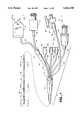
- FIG. 1is a side elevational view of the multi-purpose, multi-parameter cardiac catheter of the present invention, the catheter being shown with broken lines to display all the significant features of the catheter from its distal end to its proximal end;
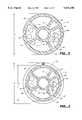
- FIG. 2is an enlarged cross-sectional view taken along the lines 2--2 of FIG. 1;
- FIG. 3is an enlarged cross-sectional view taken along lines 3--3 of FIG. 1;
- FIG. 4is an enlarged plan view taken along lines 4--4 of FIG. 1;
- FIG. 5is an exploded perspective view of the heater plug of FIG. 1;
- FIG. 6is a side elevation, partially in section, of a manifold of the catheter of FIG. 1;
- FIG. 6Ais an end view of FIG. 6 taken along lines 6A--6A of FIG. 6;
- FIG. 7is an enlarged view in partial section of a proximal notch provided near a proximal end of a thermal element and the distal end of the catheter;
- FIG. 7Ais a sectional view of the thermal element connection shown in FIG. 7;
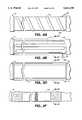
- FIG. 8is an enlarged sectional view taken at the distal end of the thermal element at the distal end of the catheter;
- FIG. 8Ais a second alternative embodiment of the thermal element of the catheter of the present invention.
- FIG. 8Bis a third alternative embodiment of the thermal element of the catheter of the present invention.
- FIG. 8Cis an enlarged cross-sectional view, taken along the lines 8C--8C of FIG. 8B;
- FIG. 8Dis a fourth alternative embodiment of the thermal element of the catheter of the present invention.
- FIG. 8Eis an enlarged cross-sectional view, taken along the lines 8E--8E of FIG. 8D;
- FIG. 8Fis a fifth alternative embodiment of the thermal element of the catheter of the present invention.
- FIG. 8Gis an enlarged cross-sectional view, taken along the lines 8G--8G of FIG. 8F;
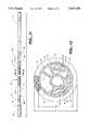
- FIG. 9is an enlarged side elevation in partial section of the distal end of the catheter.
- FIG. 10is an enlarged plan view of the distal end of the catheter, taken generally along the lines 10--10 of FIG. 1;
- FIG. 11is an enlarged view of the distal end of the catheter of FIG. 1 showing modifications occurring in the distal end of the catheter in an alternative embodiment of the present invention
- FIG. 12is a sectional view taken along the lines 12--12 of FIG. 11;
- FIG. 13is a partial view of the catheter taking a fragment of the catheter body proximal of the thermal element 55 of FIG. 11;
- FIG. 14is a partial view showing the thermal connection in the thermal element connector lumen of the catheter at the fragmented section of FIG. 13;
- FIG. 15is a view which combines FIGS. 13 and 14;
- FIG. 16is apartial view taken along the lines 16--16 of FIG. 15;
- FIG. 17is a sectional view taken at the proximal end of the thermal element of the catheter of FIG. 11 with certain parts removed for clarity;
- FIG. 18is a partial elevation taken at the distal end of the catheter and showing the necked down portion thereof;
- FIG. 19is the detail 19 of FIG. 18.
- FIG. 20is a detail view similar to FIG. 19 in which the thermal element 55 is wound about the necked down portion of the catheter.
- FIG. 1is a perspective view of the multi-purpose, multi-parameter catheter 10 of the present invention.
- the main body 12 of the catheter 10is an extended section of polyvinyl chloride (PVC) tubing.
- tubing 12is a complex multi-lumen tubing having a central lumen 13 defined by an interior PVC core 14 which is connected to a peripheral wall 16 of the tubing 12 by support ribs 17. Spaces between support ribs 17, the interior core 14 and the peripheral wall 16 define a series of interior longitudinal lumens in the catheter tubing 12.
- Central or distal lumen 13, the optics lumen 18, the balloon lumen 20, the distal thermal element pressure port lumen 22, the thermal element connector lumen 23 and the proximal lumen 24are generally parallel and coextensive for the entire working length of the catheter main body tubing 12, which in the preferred embodiment is 110 centimeters.
- a manifold 26Interposed between the catheter tubing 12 and catheter interconnects (discussed below) at the proximal end of the catheter 10 is a manifold 26 which will be described in greater detail below.
- a series of interconnects between the catheter lumensis provided at the proximal end 27 of the catheter 10 at the proximal end 27 of the catheter 10 at the proximal end 27 of the catheter 10 at the proximal end 27 of the catheter 10 at the proximal end 27 of the catheter 10 at the proximal end 27 of the catheter 10 at the proximal end 27 of the catheter 10 at the proximal end 27 of the catheter 10 at the proximal end 27 of the catheter 10 is provided a series of interconnects between the catheter lumens, with the interface between said interconnects and the catheter lumens being provided in the manifold 26.
- the first of the interconnects noted aboveis a fiber optic coupler 28.
- the coupler body 30is a molded plastic body which plugs into an optical module associated with a SVO 2 monitor (not shown).
- a pair of plug-in members 32which receive fiber optic filaments 33 (also see FIG. 4).
- fiber optic filaments 33also see FIG. 4
- a series of elongated Kevlar elements 34Included with the fiber optic filaments 33 are a series of elongated Kevlar elements 34 (FIG.
- a thermistor connector 42includes a pair of thermistor wires 43 (FIG. 2) which extend through tubing 44 connected at the thermistor connector 42 by molded fitting 46 and are received into the secondary manifold 37 and stopcock 38 to be received into the tubing 40 connected to the manifold 26.
- Luer lock fitting 47ais connected to tubing section 48a, and tubing 48a is connected at its distal end to the pulmonary artery distal lumen 13 in the manifold 26.
- the CVP luer lock 47bis connected to tubing section 48b which is in turn connected at its distal end to the proximal lumen 24 in the manifold 26.
- luer lock fitting 47cis connected at its proximal end to tubing section 48c which is in turn connected at its distal end to the distal thermal element pressure port lumen 22 in the manifold 26.
- Thermal element plug 50comprises a plastic body 51 having a cylindrical disc 52 joined thereto at a mid portion of the plug.
- the disc 52a peripheral flange which extends beyond the body 51 of the plug 50.
- Mounted in the disc 52are a plurality of metal pins 53 (FIG. 5) which extend through the plug 50 to protrude at an opposite end thereof.
- Connected to the lower end of the pins 53are thermal element connectors or wires 54 which connect to the pins 53 that protrude from the back of the disc 52 to be received into extension tubing 56 which is connected between the thermal plug 50 and the manifold 26.
- Connected to the upper ends of the pins 53is a temperature control apparatus such as described and claimed in U.S. Pat. No.
- the thermal element connectorscan be heater wires 54 as in the preferred embodiment of FIG. 1, or could be replaced by coils carrying temperature regulated fluid therein as described in greater detail below.
- the thermal element connectors 54continue through the manifold 26 into the thermal element connector lumen 23 to extend along the working length of the catheter tubing 12 to a thermal element 55, disposed near the distal end of the catheter 10.
- Stop cock 57which includes stop cock valve 58, stop cock sleeve 59 and extension tubing 60 interfaces with the balloon lumen 20 at the manifold 26.
- FIG. 6the manifold 26 is shown partly in section. Not all lumen/tubing interfaces in the manifold 26 are shown in FIG. 6, but sufficient detail is provided in FIG. 6 to give an understanding of the construction within the interior of the manifold 26.
- each extension tubeis aligned and abutted with its respective lumen of the catheter 10 at the interface thereof, the manifold 26 fixing the position of the main body tubing 12 of the catheter 10 with respect to the extension tubing.
- the tubing 40 connected to the optics lumen 18is shown in section in FIG. 6, the drawing is illustrative to depict the manifold interface for each catheter lumen and its respective extension tubing section.
- FIGS. 2 and 3can now be reexamined to understand the interior workings of the catheter 10.
- the optics, Kevlar and thermistor lumen 18includes not only optical fiber filaments 33 but also the supporting Kevlar filaments 34, as well as thermistor wires 43.
- Opposite lumen 18is the thermal element lumen 23 which receives therein thermal element connectors 54.
- FIG. 3is taken looking toward the distal end of the catheter 10 and is taken about 25 centimeters from that distal end.
- the 110 centimeter length of the catheter tubing 12is referred to as the working length, for about 85 centimeters the main body tubing 12 is essentially smooth. In the 25 centimeters of main body tubing 12 beginning at the distal end and moving forward are located many of the apparatus associated with the detection of blood-related parameters through the use of the catheter 10.
- a proximal notch 64(FIG. 7) provided in the proximal lumen 24.
- the proximal lumen 24is plugged by a solid PVC plug 66 to direct the flow of injectate into the blood stream rather than permitting it to advance in the proximal lumen 24 beyond the proximal notch 64.
- the thermal element connector wires 54emerge from the thermal element connector lumen 23 at a notch 67 (FIG. 7A).
- connector wires 54connect with bifilar wires 55a, 55b which emerge from the lumen 23 at notch 67 to thereafter circumferentially be wound about the catheter main body 12 at a reduced diameter section 68 to form a thermal element 55 about 10 centimeters long.
- Such reduced diameter section 68is also depicted in FIG. 3. Note in the reduced diameter portion 68 of catheter 10 shown in FIG. 3 that although the diameter of the tubing 68 is reduced from diameter D 1 to diameter D 2 , and that all lumens, including the optics, Kevlar and thermistor lumen 18', the balloon lumen 20', the distal thermal element pressure port lumen 22', the thermal element connector lumen 23' and the proximal lumen 24' are reduced in size, such lumens remain sufficiently large to receive and support the fiber optic filaments 33, the Kevlar filaments 34 and the thermistor wires 43 in reduced diameter section lumen 18' and the thermal element connectors 54 in reduced diameter section lumen 23'.
- thermal element 55could be mounted at the distal end of a fiber optic catheter having a catheter body of uniform cross-section at a location comparable to the reduced-diameter portion 68 and continue to provide many of the advantages ascribed to the multi-lumen, multi-purpose catheter of the preferred embodiment of the present invention.
- the opening 67is potted to cover the connection of wires 54 and 55.
- the bifilar wires 55a and 55bare of a soft copper composition and are circumferentially wound about the reduced diameter portion 68 of the catheter body 12 for about 10 centimeters and terminate at a second notch 70 in the heater wire lumen 23.
- the terminus of the thermal element wires 55a, 55bis best seen in FIG. 8 in which the wires 55a, 55b are joined to a solid PVC rod 72.
- FIGS. 7 and 8also show the pitch or spacing of the wires 55a, 55b to be 0.017" center to center.
- the notch 70is also potted to enclose the wires 55 with a polyurethane coating 74. As can also been seen in FIGS. 1, 3 and 7, a polyurethane coating 74 overlies the wires 55a, 55b for the entire length of the thermal element 55.
- FIGS. 8A through 8GAlternative embodiments of the thermal element 55 are shown in FIGS. 8A through 8G.
- a second embodiment of the thermal element 55comprises thin film member 56a, which is spiral wound about the reduced-diameter section 68 of the catheter body 12.
- a third embodiment of the thermal element 55comprises thin film sleeve 56b, incorporating a coiled conductive element 57b embedded therein in the coiled pattern shown, which overlies the reduced-diameter portion 68 of the catheter body 12.
- the relationship between the sleeve 56b and the catheter body 12 at reduced-diameter portion 68is better seen in the enlarged cross-sectional view of FIG. 8C.
- a fourth embodiment of the thermal element 55comprises a self-regulating conductive plastic sleeve 55d, incorporating power wires 57d, on opposite sides thereof as shown in FIG. 8E, mounted on the reduced-diameter section 68 of the catheter body 12.
- a fifth embodiment of the thermal element 55comprises a heat exchanger 55f, having an interior fluid-filled jacket 56f, an exterior sheath 57f, and coils (not shown) comparable to connectors 54 associated therewith, to transfer thermally regulated fluids from an external heat exchanger (not shown) to heat exchanger 55f.
- each thermal element 55a-55fis connected to an appropriate thermal regulator or heater exchanger (not shown) by thermal wires or coils 54 extending from the thermal element 55 to an appropriate connector, comparable to thermal plug 51, disposed at the proximal end of the catheter 10.
- a distal thermal pressure port 76(FIG. 1).
- the distal thermal pressure port 76is very similar to the proximal notch 64 and the structural details of the proximal notch 64 as shown in FIG. 7 apply equally to the pressure port 76.
- the distal thermal pressure port 76can be used with the lumen 22 as an injectate lumen, or, because of its proximity to the distal end of thermal element 55 can be used with the appropriate monitoring capabilities of the CCO monitor, shown in above-mentioned U.S. Pat. No. 5,277,191 to serve as a locator for the thermal element 55.
- waveform monitoring at the distal thermal pressure port 76would substantially facilitate placement of the thermal element 55 of the catheter 12 in the right ventricle of the heart, a preferred location for the thermal element for the generation of continuous cardiac output data. That is the waveform generated in the right ventricle is substantially different from the waveform generated in the pulmonary artery and identification of the ventricular waveform enables placement of the thermal element 55 in the right ventricle of the patient's heart.
- Thermistor 77is exposed to the blood stream and senses the temperature therein.
- the distal end of the catheter body 12shows a balloon 78 secured to the catheter body 12 at opposite ends 78a and 78b by adhesive 80.
- the balloon 78is attached to the periphery of the catheter body 12 and is inflated through the balloon lumen 20 at an opening 81 which opens into the balloon lumen 20 at the distal end of the catheter 10.
- the balloon 78is inflated by a means well known in the art.
- the distal end of the catheter as seen in FIG. 10includes an open port 79 which is the exit port 79 for the distal lumen 13 and a closed port 80 which is the distal port 80 for the optics, Kevlar and thermistor lumen 18. Exposed at the distal end 82 of the catheter body 12 are the ends 83 of optical fibers 33.
- FIGS. 11-17An alternative embodiment of the catheter of the present invention is shown in FIGS. 11-17.
- the alternative embodimentis similar to the first embodiment in all respects except for the changes at the distal end of the catheter. Accordingly an enlarged view of the distal end of the catheter is shown in FIG. 11.
- transitional opening 83is proximal of opening 84a in which the beginning of the thermal element 55 begins to wind around the necked down portion of the catheter body 12.
- Similar opening 84bis provided at the distal end of the thermal element 55.
- locators for the thermal element 55are radio-opaque markers 86a and 86b at opposite ends of the heater element.
- the necked down portion of the catheter 12is substantially modified to maintain the size and shape of the optics, Kevlar and thermistor lumen 18', the balloon lumen 20', the central lumen 13' and the distal thermal pressure port lumen 22'.
- the size and shape of the thermal element connector lumen 23' and the proximal lumen 24'have been considerably reduced to accommodate the reduced size of the catheter body 12 at the necked down portion of the catheter.
- the thermal element connector lumen 23'terminates at the necked down portion of the catheter there is no reason to maintain the size and shape of such lumen throughout the necked down portion of the catheter.
- the discharge point of the proximal lumen 24is proximal of the heater element of 55 and there is no need to maintain the size and shape of the proximal lumen 24' in the necked down portion of the catheter body. Further, by maintaining the size and shape of lumens 13', 18', 20' and 22' at the necked down portion of the catheter substantially maintains consistent catheter function of all lumens for the entire working length of the catheter 12.
- FIGS. 13-17Further modifications to the catheter body 12 are accomplished in FIGS. 13-17 to effect a smooth transition of the bifilar thermal coils which comprise the thermal element 55 and are wrapped around the necked down portion 68 of the catheter.
- the catheter body 12 adjacent to a proximal end of the thermal element 55includes an opening 83. Disposed in the opening 83 are the thermal connectors 54. Bifilar wires 88a and 88b are wrapped around respective thermal connector ends 54a, 54b to emerge from opening 90 at the proximal end of the necked down portion and wrap around the necked down portion 68 to form the thermal element 55.
- FIG. 17provides a sectional view along the axis of the catheter 12 at the connection between wires 88 and connectors 54 in which thermal element wire 88b and connector wire 54b have been deleted.
- the effect of the modified connection between the thermal element wires 88a, 88b and the heater connectors 54a, 54benables a smoother transition between the two wires to achieve better flex at the proximal end of the thermal element 55 and to accomplish strain relief at the interface of the connectors 54 and the thermal element 55.
- a polyurethane coating 74is applied as the thermal element wire 88 is wound around the catheter at the necked down section 68, the coating 74 overlying the necked down section as shown in FIG. 12 to complete the assembly.
- the alternative embodimentprovides an improvement in the interface between the connectors 54 and the thermal element wires 88. Further, the modified lumens at the interior of the catheter body at the necked down section substantially maintain the size and shape of the remaining lumens which extend therethrough to the distal end of the catheter body 12. Thus, the alternative embodiment of FIGS. 11-17 provides an additional configuration which also maintains the efficacy of the catheter lumens in the necked down section of the catheter.
- FIGS. 18-20show a further modification of the catheter 12 in the necked down portion 68 in an alternative embodiment of the present invention.
- disposed at opposite ends of the necked down portion 68are sloped shoulders 68a and 68b.
- a helix angle provided at shoulders 68a, 68bmatches the pitch angle of bifilar coil wires 55a and 55b such that first and last turns of wires 55a, 55b are parallel to the shoulder which allows an easy blending of the urethane overcoat 74.
- the shoulders 68a and 68beach have grooves 90 tapering downward from the neck down surface.
- the bifilar coil wiretends to roll up on edge as it enters the notch.
- the groove 90allows the wires 55 to stay at a low profile so as not to create a bump in the otherwise smooth overcoat.
- a micro-notch 90ais in the deepest end of the groove. Minimizing the notch size allows the thermal element coil 55 to be wound right up to the shoulder for easy blending for the urethane overcoat 74.
- the catheter 10 of the present inventionincorporates thermal element 55 at a reduced diameter portion of the catheter body 12 coil for use in the measurement of continuous cardiac output measurement, such measurement taken in conjunction with the thermistor 77 located distal to the thermal element 55.
- thermal element 55for use in an application for measurement of continuous cardiac output, please refer to U.S. Pat. No. 5,277,191 noted above.
- thermal element 55into the catheter body 12 for the measurement of continuous cardiac output is achieved with no loss in the capability of the catheter to provide a measurement of oxygen concentration or SVO 2 in the blood through the use of fiber optics as described in U.S. Pat. No. 4,453,218 entitled "Signal Filter Method and Apparatus" and assigned to the assignee of the present invention.
- Such dual capacityis permitted by the provision of a reduced diameter body portion of the catheter body 12 which reduces not only the diameter of the catheter body at such body portion but also reduces the size of the lumens in which the heater wires are located and the proximal lumen.
- a reduced diameter body portion of the catheter body 12which reduces not only the diameter of the catheter body at such body portion but also reduces the size of the lumens in which the heater wires are located and the proximal lumen.
- such reduction in lumen sizeis not adverse to fiber optic performance as it relates to measurement of SVO 2 or to thermistor performance as it relates to the measurement of temperature.
- the reduced diameter portion of the catheter 10has no impact on the efficacy of the thermal element connectors 54 used in the thermal element 55.
- the reduced diameter catheter body portionhave any effect on the flow of injectates through the flow ports or the removal of samples through those ports.
- the reduced diameter portion 68 of the catheter body 12has no impact on the measurements to be taken by the catheter 10 in connection with the evaluation of separate blood-related parameters associated with oxygen saturation, continuous cardiac output and thermal dilution values.
- the catheter 10is useable for continuous cardiac output measurements and has a symmetric diameter for its entire working length.
- An alternative construction, such as a catheter body of a single diameter throughout its working length, which then wound a thermal element about the distal end thereofwould produce a discontinuity in such catheter and such discontinuity could be noticeable in the insertion and removal of such catheter.
- the multi-purpose, multi-parameter cardiac catheter of the present inventionincorporates the thermal element at a reduced diameter section thereof at the distal end of the catheter and yet generally maintains a single diameter throughout the working length of the catheter, because the addition of the thermal element and coating at the reduced diameter portion creates an overall diameter at that portion that is consistent with the diameter at the remainder of the working length of the catheter. Consistency of diametric proportions throughout the working length of the catheter should facilitate insertion and removal of the catheter of the preferred embodiment of the present invention.
Landscapes
- Health & Medical Sciences (AREA)
- Life Sciences & Earth Sciences (AREA)
- Physics & Mathematics (AREA)
- Molecular Biology (AREA)
- Animal Behavior & Ethology (AREA)
- Veterinary Medicine (AREA)
- Biophysics (AREA)
- Pathology (AREA)
- Engineering & Computer Science (AREA)
- Biomedical Technology (AREA)
- Heart & Thoracic Surgery (AREA)
- Medical Informatics (AREA)
- Public Health (AREA)
- Surgery (AREA)
- General Health & Medical Sciences (AREA)
- Physiology (AREA)
- Hematology (AREA)
- Cardiology (AREA)
- Spectroscopy & Molecular Physics (AREA)
- Optics & Photonics (AREA)
- Measuring Pulse, Heart Rate, Blood Pressure Or Blood Flow (AREA)
- Measurement Of The Respiration, Hearing Ability, Form, And Blood Characteristics Of Living Organisms (AREA)
- Media Introduction/Drainage Providing Device (AREA)
- Measuring And Recording Apparatus For Diagnosis (AREA)
- Electrotherapy Devices (AREA)
- Apparatus For Radiation Diagnosis (AREA)
Abstract
Description
Claims (18)
Priority Applications (1)
| Application Number | Priority Date | Filing Date | Title |
|---|---|---|---|
| US08/315,033US5611338A (en) | 1992-07-16 | 1994-09-29 | Multi-purpose multi-parameter cardiac catheter |
Applications Claiming Priority (2)
| Application Number | Priority Date | Filing Date | Title |
|---|---|---|---|
| US07/914,279US5435308A (en) | 1992-07-16 | 1992-07-16 | Multi-purpose multi-parameter cardiac catheter |
| US08/315,033US5611338A (en) | 1992-07-16 | 1994-09-29 | Multi-purpose multi-parameter cardiac catheter |
Related Parent Applications (1)
| Application Number | Title | Priority Date | Filing Date |
|---|---|---|---|
| US07/914,279Continuation-In-PartUS5435308A (en) | 1992-07-16 | 1992-07-16 | Multi-purpose multi-parameter cardiac catheter |
Publications (1)
| Publication Number | Publication Date |
|---|---|
| US5611338Atrue US5611338A (en) | 1997-03-18 |
Family
ID=25434126
Family Applications (3)
| Application Number | Title | Priority Date | Filing Date |
|---|---|---|---|
| US07/914,279Expired - LifetimeUS5435308A (en) | 1992-07-16 | 1992-07-16 | Multi-purpose multi-parameter cardiac catheter |
| US08/300,272Expired - LifetimeUS5634720A (en) | 1992-07-16 | 1994-09-02 | Multi-purpose multi-parameter cardiac catheter |
| US08/315,033Expired - LifetimeUS5611338A (en) | 1992-07-16 | 1994-09-29 | Multi-purpose multi-parameter cardiac catheter |
Family Applications Before (2)
| Application Number | Title | Priority Date | Filing Date |
|---|---|---|---|
| US07/914,279Expired - LifetimeUS5435308A (en) | 1992-07-16 | 1992-07-16 | Multi-purpose multi-parameter cardiac catheter |
| US08/300,272Expired - LifetimeUS5634720A (en) | 1992-07-16 | 1994-09-02 | Multi-purpose multi-parameter cardiac catheter |
Country Status (11)
| Country | Link |
|---|---|
| US (3) | US5435308A (en) |
| EP (1) | EP0652727B1 (en) |
| JP (1) | JP3273612B2 (en) |
| AT (1) | ATE205681T1 (en) |
| AU (1) | AU677593B2 (en) |
| CA (1) | CA2139780C (en) |
| DE (1) | DE69330792T2 (en) |
| DK (1) | DK0652727T3 (en) |
| ES (1) | ES2162821T3 (en) |
| PT (1) | PT652727E (en) |
| WO (1) | WO1994002066A1 (en) |
Cited By (29)
| Publication number | Priority date | Publication date | Assignee | Title |
|---|---|---|---|---|
| WO1998032373A1 (en)* | 1997-01-24 | 1998-07-30 | Eggers Philip E | Method, system and apparatus for evaluating hemodynamic parameters |
| US5916171A (en)* | 1994-05-31 | 1999-06-29 | Mayevsky; Avraham | Tissue monitor |
| US5928155A (en)* | 1997-01-24 | 1999-07-27 | Cardiox Corporation | Cardiac output measurement with metabolizable analyte containing fluid |
| US6004275A (en)* | 1995-04-14 | 1999-12-21 | Billiet; Erik | System for the measurement of continuous cardiac output |
| US6210363B1 (en)* | 1999-02-23 | 2001-04-03 | Cardeon Corporation | Methods and devices for occluding a vessel and performing differential perfusion |
| US6299583B1 (en) | 1998-03-17 | 2001-10-09 | Cardiox Corporation | Monitoring total circulating blood volume and cardiac output |
| US6383144B1 (en) | 2000-01-18 | 2002-05-07 | Edwards Lifesciences Corporation | Devices and methods for measuring temperature of a patient |
| US20020077564A1 (en)* | 1996-07-29 | 2002-06-20 | Farallon Medsystems, Inc. | Thermography catheter |
| US20020111662A1 (en)* | 2001-02-09 | 2002-08-15 | Iaizzo Paul A. | System and method for placing an implantable medical device within a body |
| US6475159B1 (en) | 1995-09-20 | 2002-11-05 | S. Ward Casscells | Method of detecting vulnerable atherosclerotic plaque |
| US20030171691A1 (en)* | 1999-06-25 | 2003-09-11 | Casscells S. Ward | Method and apparatus for detecting vulnerable atherosclerotic plaque |
| US20040073132A1 (en)* | 2002-05-07 | 2004-04-15 | Tracy Maahs | Systems and methods for detecting vulnerable plaque |
| US6763261B2 (en) | 1995-09-20 | 2004-07-13 | Board Of Regents, The University Of Texas System | Method and apparatus for detecting vulnerable atherosclerotic plaque |
| US7123968B1 (en) | 1996-09-20 | 2006-10-17 | The Board Of Regents Of The University Of Texas System | Heat treatment of inflamed tissue |
| US20070044809A1 (en)* | 2005-08-29 | 2007-03-01 | Dawn Flynn | Disposable sheath for telementry leads of a monitoring device |
| US20070167861A1 (en)* | 2005-11-29 | 2007-07-19 | Lopez George A | Cardiac output measurement devices and methods |
| US20070276210A1 (en)* | 2003-11-14 | 2007-11-29 | Guillermo Gutierrez | Apparatus and method for measuring myocardial oxygen consumption |
| US20080161797A1 (en)* | 2006-12-29 | 2008-07-03 | Huisun Wang | Ablation catheter electrode having multiple thermal sensors and method of use |
| US7603166B2 (en) | 1996-09-20 | 2009-10-13 | Board Of Regents University Of Texas System | Method and apparatus for detection of vulnerable atherosclerotic plaque |
| US20110282217A1 (en)* | 2008-12-03 | 2011-11-17 | Omega Critical Care Limited | Method and device for determining dysfunction of the heart |
| US20130295192A1 (en)* | 2012-03-30 | 2013-11-07 | Russel Hirsch | Method to identify tissue oxygenation state by spectrographic analysis |
| US10960176B2 (en) | 2014-12-19 | 2021-03-30 | Hospital For Special Surgery | Multi-catheter infusion system and method thereof |
| US11622695B1 (en) | 2020-04-23 | 2023-04-11 | Shifamed Holdings, Llc | Intracardiac sensors with switchable configurations and associated systems and methods |
| US11633194B2 (en) | 2020-11-12 | 2023-04-25 | Shifamed Holdings, Llc | Adjustable implantable devices and associated methods |
| US11801369B2 (en) | 2020-08-25 | 2023-10-31 | Shifamed Holdings, Llc | Adjustable interatrial shunts and associated systems and methods |
| US12090290B2 (en) | 2021-03-09 | 2024-09-17 | Shifamed Holdings, Llc | Shape memory actuators for adjustable shunting systems, and associated systems and methods |
| WO2024206174A1 (en)* | 2023-03-24 | 2024-10-03 | Edwards Lifesciences Corporation | Systems and methods for continuous cardiac output monitoring |
| US12151071B2 (en) | 2019-09-09 | 2024-11-26 | Shifamed Holdings, Llc | Adjustable shunts and associated systems and methods |
| US12440656B2 (en) | 2021-04-23 | 2025-10-14 | Shifamed Holdings, Llc | Power management for interatrial shunts and associated systems and methods |
Families Citing this family (118)
| Publication number | Priority date | Publication date | Assignee | Title |
|---|---|---|---|---|
| US6387052B1 (en)* | 1991-01-29 | 2002-05-14 | Edwards Lifesciences Corporation | Thermodilution catheter having a safe, flexible heating element |
| US5435308A (en)* | 1992-07-16 | 1995-07-25 | Abbott Laboratories | Multi-purpose multi-parameter cardiac catheter |
| US6161543A (en) | 1993-02-22 | 2000-12-19 | Epicor, Inc. | Methods of epicardial ablation for creating a lesion around the pulmonary veins |
| US6036654A (en)* | 1994-09-23 | 2000-03-14 | Baxter International Inc. | Multi-lumen, multi-parameter catheter |
| US6409722B1 (en) | 1998-07-07 | 2002-06-25 | Medtronic, Inc. | Apparatus and method for creating, maintaining, and controlling a virtual electrode used for the ablation of tissue |
| US5897553A (en) | 1995-11-02 | 1999-04-27 | Medtronic, Inc. | Ball point fluid-assisted electrocautery device |
| US5865801A (en)* | 1995-07-18 | 1999-02-02 | Houser; Russell A. | Multiple compartmented balloon catheter with external pressure sensing |
| US5673694A (en)* | 1995-08-08 | 1997-10-07 | Henry Ford Health System | Method and apparatus for continuous measurement of central venous oxygen saturation |
| NL1003024C2 (en) | 1996-05-03 | 1997-11-06 | Tjong Hauw Sie | Stimulus conduction blocking instrument. |
| US5689958A (en)* | 1996-09-27 | 1997-11-25 | The United States Of America As Represented By The Secretary Of The Air Force | High efficiency thermal electric cooler driver |
| US6237605B1 (en) | 1996-10-22 | 2001-05-29 | Epicor, Inc. | Methods of epicardial ablation |
| US7052493B2 (en) | 1996-10-22 | 2006-05-30 | Epicor Medical, Inc. | Methods and devices for ablation |
| US6719755B2 (en) | 1996-10-22 | 2004-04-13 | Epicor Medical, Inc. | Methods and devices for ablation |
| US6840936B2 (en) | 1996-10-22 | 2005-01-11 | Epicor Medical, Inc. | Methods and devices for ablation |
| US6805128B1 (en) | 1996-10-22 | 2004-10-19 | Epicor Medical, Inc. | Apparatus and method for ablating tissue |
| US6311692B1 (en) | 1996-10-22 | 2001-11-06 | Epicor, Inc. | Apparatus and method for diagnosis and therapy of electrophysiological disease |
| US6827710B1 (en) | 1996-11-26 | 2004-12-07 | Edwards Lifesciences Corporation | Multiple lumen access device |
| US6096037A (en) | 1997-07-29 | 2000-08-01 | Medtronic, Inc. | Tissue sealing electrosurgery device and methods of sealing tissue |
| US8709007B2 (en) | 1997-10-15 | 2014-04-29 | St. Jude Medical, Atrial Fibrillation Division, Inc. | Devices and methods for ablating cardiac tissue |
| US6368304B1 (en) | 1999-02-19 | 2002-04-09 | Alsius Corporation | Central venous catheter with heat exchange membrane |
| US6419643B1 (en) | 1998-04-21 | 2002-07-16 | Alsius Corporation | Central venous catheter with heat exchange properties |
| US6682551B1 (en) | 1999-03-11 | 2004-01-27 | Alsius Corporation | Method and system for treating cardiac arrest using hypothermia |
| US6527767B2 (en)* | 1998-05-20 | 2003-03-04 | New England Medical Center | Cardiac ablation system and method for treatment of cardiac arrhythmias and transmyocardial revascularization |
| US6537248B2 (en) | 1998-07-07 | 2003-03-25 | Medtronic, Inc. | Helical needle apparatus for creating a virtual electrode used for the ablation of tissue |
| US6706039B2 (en) | 1998-07-07 | 2004-03-16 | Medtronic, Inc. | Method and apparatus for creating a bi-polar virtual electrode used for the ablation of tissue |
| US6969379B1 (en) | 1998-08-27 | 2005-11-29 | A-Med Systems, Inc. | Intravascular cannulation apparatus and methods of use |
| JP2002525138A (en)* | 1998-08-27 | 2002-08-13 | エイ−メド システムズ, インコーポレイテッド | Intravascular cannula insertion device and method of use |
| US8308719B2 (en) | 1998-09-21 | 2012-11-13 | St. Jude Medical, Atrial Fibrillation Division, Inc. | Apparatus and method for ablating tissue |
| US6582398B1 (en) | 1999-02-19 | 2003-06-24 | Alsius Corporation | Method of managing patient temperature with a heat exchange catheter |
| US6287319B1 (en) | 1999-03-30 | 2001-09-11 | Amed Systems, Inc. | Cannula with balloon tip |
| US6295877B1 (en) | 1999-03-30 | 2001-10-02 | A-Med Systems, Inc. | Pressure sensing cannula |
| EP1207788A4 (en) | 1999-07-19 | 2009-12-09 | St Jude Medical Atrial Fibrill | Apparatus and method for ablating tissue |
| US7022100B1 (en) | 1999-09-03 | 2006-04-04 | A-Med Systems, Inc. | Guidable intravascular blood pump and related methods |
| US6394961B1 (en) | 1999-10-28 | 2002-05-28 | Pulsion Medical Systems Ag | Method to increase transpulmonary thermodilution cardiac output accuracy by use of extravascular thermovolume to control the amount of thermal indicator |
| US6592544B1 (en)* | 1999-11-24 | 2003-07-15 | Edwards Lifesciences Corporation | Vascular access devices having hemostatic safety valve |
| US6447443B1 (en) | 2001-01-13 | 2002-09-10 | Medtronic, Inc. | Method for organ positioning and stabilization |
| US6692450B1 (en) | 2000-01-19 | 2004-02-17 | Medtronic Xomed, Inc. | Focused ultrasound ablation devices having selectively actuatable ultrasound emitting elements and methods of using the same |
| US8221402B2 (en) | 2000-01-19 | 2012-07-17 | Medtronic, Inc. | Method for guiding a medical device |
| US7706882B2 (en) | 2000-01-19 | 2010-04-27 | Medtronic, Inc. | Methods of using high intensity focused ultrasound to form an ablated tissue area |
| US8048070B2 (en) | 2000-03-06 | 2011-11-01 | Salient Surgical Technologies, Inc. | Fluid-assisted medical devices, systems and methods |
| US8527046B2 (en) | 2000-04-20 | 2013-09-03 | Medtronic, Inc. | MRI-compatible implantable device |
| US6925328B2 (en) | 2000-04-20 | 2005-08-02 | Biophan Technologies, Inc. | MRI-compatible implantable device |
| US6488680B1 (en) | 2000-04-27 | 2002-12-03 | Medtronic, Inc. | Variable length electrodes for delivery of irrigated ablation |
| DE60111517T2 (en) | 2000-04-27 | 2006-05-11 | Medtronic, Inc., Minneapolis | VIBRATION-SENSITIVE ABLATION DEVICE |
| US6514250B1 (en) | 2000-04-27 | 2003-02-04 | Medtronic, Inc. | Suction stabilized epicardial ablation devices |
| US6926669B1 (en) | 2000-10-10 | 2005-08-09 | Medtronic, Inc. | Heart wall ablation/mapping catheter and method |
| US7740623B2 (en) | 2001-01-13 | 2010-06-22 | Medtronic, Inc. | Devices and methods for interstitial injection of biologic agents into tissue |
| US20040138621A1 (en) | 2003-01-14 | 2004-07-15 | Jahns Scott E. | Devices and methods for interstitial injection of biologic agents into tissue |
| US7628780B2 (en) | 2001-01-13 | 2009-12-08 | Medtronic, Inc. | Devices and methods for interstitial injection of biologic agents into tissue |
| US20020095203A1 (en)* | 2001-01-18 | 2002-07-18 | Intra Therapeutics, Inc. | Catheter system with spacer member |
| GB0103886D0 (en)* | 2001-02-16 | 2001-04-04 | Baumbach Per L | Temperature measuring device |
| US20020116028A1 (en) | 2001-02-20 | 2002-08-22 | Wilson Greatbatch | MRI-compatible pacemaker with pulse carrying photonic catheter providing VOO functionality |
| US6829509B1 (en) | 2001-02-20 | 2004-12-07 | Biophan Technologies, Inc. | Electromagnetic interference immune tissue invasive system |
| US7959626B2 (en) | 2001-04-26 | 2011-06-14 | Medtronic, Inc. | Transmural ablation systems and methods |
| US6807968B2 (en) | 2001-04-26 | 2004-10-26 | Medtronic, Inc. | Method and system for treatment of atrial tachyarrhythmias |
| US7250048B2 (en) | 2001-04-26 | 2007-07-31 | Medtronic, Inc. | Ablation system and method of use |
| US6648883B2 (en) | 2001-04-26 | 2003-11-18 | Medtronic, Inc. | Ablation system and method of use |
| US6663627B2 (en) | 2001-04-26 | 2003-12-16 | Medtronic, Inc. | Ablation system and method of use |
| US6699240B2 (en) | 2001-04-26 | 2004-03-02 | Medtronic, Inc. | Method and apparatus for tissue ablation |
| US6731979B2 (en) | 2001-08-30 | 2004-05-04 | Biophan Technologies Inc. | Pulse width cardiac pacing apparatus |
| US7054686B2 (en) | 2001-08-30 | 2006-05-30 | Biophan Technologies, Inc. | Pulsewidth electrical stimulation |
| EP1435867B1 (en) | 2001-09-05 | 2010-11-17 | Salient Surgical Technologies, Inc. | Fluid-assisted medical devices and systems |
| US6697653B2 (en) | 2001-10-10 | 2004-02-24 | Datex-Ohmeda, Inc. | Reduced wire count voltage drop sense |
| US6988001B2 (en) | 2001-10-31 | 2006-01-17 | Biophan Technologies, Inc. | Hermetic component housing for photonic catheter |
| US6656175B2 (en) | 2001-12-11 | 2003-12-02 | Medtronic, Inc. | Method and system for treatment of atrial tachyarrhythmias |
| US7967816B2 (en) | 2002-01-25 | 2011-06-28 | Medtronic, Inc. | Fluid-assisted electrosurgical instrument with shapeable electrode |
| US6827715B2 (en) | 2002-01-25 | 2004-12-07 | Medtronic, Inc. | System and method of performing an electrosurgical procedure |
| US6968236B2 (en) | 2002-01-28 | 2005-11-22 | Biophan Technologies, Inc. | Ceramic cardiac electrodes |
| US6711440B2 (en) | 2002-04-11 | 2004-03-23 | Biophan Technologies, Inc. | MRI-compatible medical device with passive generation of optical sensing signals |
| US6725092B2 (en) | 2002-04-25 | 2004-04-20 | Biophan Technologies, Inc. | Electromagnetic radiation immune medical assist device adapter |
| US7118566B2 (en) | 2002-05-16 | 2006-10-10 | Medtronic, Inc. | Device and method for needle-less interstitial injection of fluid for ablation of cardiac tissue |
| US7294143B2 (en) | 2002-05-16 | 2007-11-13 | Medtronic, Inc. | Device and method for ablation of cardiac tissue |
| US6925322B2 (en) | 2002-07-25 | 2005-08-02 | Biophan Technologies, Inc. | Optical MRI catheter system |
| US6850789B2 (en)* | 2002-07-29 | 2005-02-01 | Welch Allyn, Inc. | Combination SPO2/temperature measuring apparatus |
| US6819951B2 (en)* | 2002-09-24 | 2004-11-16 | Mayo Foundation For Medical Education And Research | Peripherally inserted central catheter with continuous central venous oximetry and proximal high flow port |
| DE10245416B4 (en) | 2002-09-28 | 2006-03-16 | Pulsion Medical Systems Ag | Catheter system with special fasteners |
| US7083620B2 (en) | 2002-10-30 | 2006-08-01 | Medtronic, Inc. | Electrosurgical hemostat |
| US7278984B2 (en) | 2002-12-31 | 2007-10-09 | Alsius Corporation | System and method for controlling rate of heat exchange with patient |
| US7497857B2 (en) | 2003-04-29 | 2009-03-03 | Medtronic, Inc. | Endocardial dispersive electrode for use with a monopolar RF ablation pen |
| US7181260B2 (en)* | 2003-11-14 | 2007-02-20 | Guillermo Gutierrez | Apparatus and method for measuring myocardial oxygen consumption |
| US8333764B2 (en) | 2004-05-12 | 2012-12-18 | Medtronic, Inc. | Device and method for determining tissue thickness and creating cardiac ablation lesions |
| JP2007537011A (en) | 2004-05-14 | 2007-12-20 | メドトロニック・インコーポレーテッド | Method and apparatus for treating atrial fibrillation by reducing mass |
| WO2005120374A1 (en) | 2004-06-02 | 2005-12-22 | Medtronic, Inc. | Compound bipolar ablation device and method |
| EP1750607A2 (en) | 2004-06-02 | 2007-02-14 | Medtronic, Inc. | Loop ablation apparatus and method |
| ATE516762T1 (en) | 2004-06-02 | 2011-08-15 | Medtronic Inc | ABLATION AND STAPLE INSTRUMENT |
| WO2005120376A2 (en) | 2004-06-02 | 2005-12-22 | Medtronic, Inc. | Ablation device with jaws |
| US8409219B2 (en) | 2004-06-18 | 2013-04-02 | Medtronic, Inc. | Method and system for placement of electrical lead inside heart |
| US8663245B2 (en) | 2004-06-18 | 2014-03-04 | Medtronic, Inc. | Device for occlusion of a left atrial appendage |
| US8926635B2 (en)* | 2004-06-18 | 2015-01-06 | Medtronic, Inc. | Methods and devices for occlusion of an atrial appendage |
| US7769451B2 (en)* | 2005-04-28 | 2010-08-03 | Medtronic, Inc. | Method and apparatus for optimizing cardiac resynchronization therapy |
| US9155896B2 (en)* | 2005-12-22 | 2015-10-13 | Cardiac Pacemakers, Inc. | Method and apparatus for improving cardiac efficiency based on myocardial oxygen consumption |
| US20080039746A1 (en) | 2006-05-25 | 2008-02-14 | Medtronic, Inc. | Methods of using high intensity focused ultrasound to form an ablated tissue area containing a plurality of lesions |
| DE102007035847A1 (en) | 2007-07-31 | 2009-02-05 | Iprm Intellectual Property Rights Management Ag | Catheter system with optical probe and method for applying an optical probe to a catheter system |
| US8882756B2 (en) | 2007-12-28 | 2014-11-11 | Medtronic Advanced Energy Llc | Fluid-assisted electrosurgical devices, methods and systems |
| EP2303171A2 (en) | 2008-05-13 | 2011-04-06 | Medtronic, Inc. | Tissue lesion evaluation |
| JP2010102030A (en)* | 2008-10-22 | 2010-05-06 | Canon Inc | Light emitting device, and image display device using the same |
| US9254168B2 (en) | 2009-02-02 | 2016-02-09 | Medtronic Advanced Energy Llc | Electro-thermotherapy of tissue using penetrating microelectrode array |
| EP2398416B1 (en) | 2009-02-23 | 2015-10-28 | Medtronic Advanced Energy LLC | Fluid-assisted electrosurgical device |
| US9345541B2 (en) | 2009-09-08 | 2016-05-24 | Medtronic Advanced Energy Llc | Cartridge assembly for electrosurgical devices, electrosurgical unit and methods of use thereof |
| US20110201908A1 (en)* | 2010-02-17 | 2011-08-18 | Farkas Joshua D | Intermittent extracorporeal spectrophotometry |
| EP2544616B1 (en) | 2010-03-11 | 2017-09-06 | Medtronic Advanced Energy LLC | Bipolar electrosurgical cutter with position insensitive return electrode contact |
| US20110295249A1 (en)* | 2010-05-28 | 2011-12-01 | Salient Surgical Technologies, Inc. | Fluid-Assisted Electrosurgical Devices, and Methods of Manufacture Thereof |
| US9138289B2 (en) | 2010-06-28 | 2015-09-22 | Medtronic Advanced Energy Llc | Electrode sheath for electrosurgical device |
| US8920417B2 (en) | 2010-06-30 | 2014-12-30 | Medtronic Advanced Energy Llc | Electrosurgical devices and methods of use thereof |
| US8906012B2 (en) | 2010-06-30 | 2014-12-09 | Medtronic Advanced Energy Llc | Electrosurgical devices with wire electrode |
| CA2746948C (en) | 2010-07-21 | 2019-01-15 | Diros Technology Inc. | Advanced multi-purpose catheter probes for diagnostic and therapeutic procedures |
| US9023040B2 (en) | 2010-10-26 | 2015-05-05 | Medtronic Advanced Energy Llc | Electrosurgical cutting devices |
| US9427281B2 (en) | 2011-03-11 | 2016-08-30 | Medtronic Advanced Energy Llc | Bronchoscope-compatible catheter provided with electrosurgical device |
| US9750565B2 (en) | 2011-09-30 | 2017-09-05 | Medtronic Advanced Energy Llc | Electrosurgical balloons |
| US8870864B2 (en) | 2011-10-28 | 2014-10-28 | Medtronic Advanced Energy Llc | Single instrument electrosurgery apparatus and its method of use |
| DE102012107090A1 (en)* | 2012-08-02 | 2014-02-06 | Phoenix Contact Gmbh & Co. Kg | Multi-conductor measuring device for detecting a faulty, temperature-dependent resistance sensor |
| US9445725B2 (en)* | 2012-12-17 | 2016-09-20 | Biosense Webster (Israel) Ltd. | Irrigated catheter tip with temperature sensor array |
| US9974599B2 (en) | 2014-08-15 | 2018-05-22 | Medtronic Ps Medical, Inc. | Multipurpose electrosurgical device |
| US11389227B2 (en) | 2015-08-20 | 2022-07-19 | Medtronic Advanced Energy Llc | Electrosurgical device with multivariate control |
| US11051875B2 (en) | 2015-08-24 | 2021-07-06 | Medtronic Advanced Energy Llc | Multipurpose electrosurgical device |
| US10716612B2 (en) | 2015-12-18 | 2020-07-21 | Medtronic Advanced Energy Llc | Electrosurgical device with multiple monopolar electrode assembly |
| US10194975B1 (en) | 2017-07-11 | 2019-02-05 | Medtronic Advanced Energy, Llc | Illuminated and isolated electrosurgical apparatus |
| US12023082B2 (en) | 2017-10-06 | 2024-07-02 | Medtronic Advanced Energy Llc | Hemostatic thermal sealer |
Citations (5)
| Publication number | Priority date | Publication date | Assignee | Title |
|---|---|---|---|---|
| US4217910A (en)* | 1978-10-10 | 1980-08-19 | The United States Of America As Represented By The Secretary Of The Navy | Internal jugular and left ventricular thermodilution catheter |
| US4776340A (en)* | 1987-03-23 | 1988-10-11 | Spectramed, Inc. | Hematocrit measurement by differential optical geometry in a short-term diagnostic cardiovascular catheter, and application to correction of blood-oxygen measurement |
| US4785823A (en)* | 1987-07-21 | 1988-11-22 | Robert F. Shaw | Methods and apparatus for performing in vivo blood thermodilution procedures |
| US4941475A (en)* | 1988-08-30 | 1990-07-17 | Spectramed, Inc. | Thermodilution by heat exchange |
| US5435308A (en)* | 1992-07-16 | 1995-07-25 | Abbott Laboratories | Multi-purpose multi-parameter cardiac catheter |
Family Cites Families (13)
| Publication number | Priority date | Publication date | Assignee | Title |
|---|---|---|---|---|
| US3472073A (en)* | 1967-06-30 | 1969-10-14 | Thermo Electric Co Inc | Linearized thermocouple measuring circuit |
| US4294116A (en)* | 1980-03-14 | 1981-10-13 | Omron Tateisi Electronics Co. | Temperature detecting circuit |
| US4453218A (en) | 1980-11-24 | 1984-06-05 | Oximetrix, Inc. | Signal filter method and apparatus |
| JPS58210530A (en)* | 1982-05-31 | 1983-12-07 | Hideo Sugimori | Resistance thermometer |
| JPS62207435A (en) | 1986-03-07 | 1987-09-11 | テルモ株式会社 | Catheter for measuring cardiac output |
| US4718423A (en) | 1986-10-17 | 1988-01-12 | Spectramed, Inc. | Multiple-function cardiovascular catheter system with very high lumenal efficiency and no crossovers |
| AU606811B2 (en)* | 1988-08-30 | 1991-02-14 | Spectramed, Inc. | Apparatus and method for determining cardiac output by thermodilution without injection |
| DE3933311A1 (en)* | 1989-10-05 | 1991-04-18 | Endress Hauser Gmbh Co | TEMPERATURE MEASURING |
| DE3940341A1 (en)* | 1989-12-06 | 1991-06-13 | Bosch Gmbh Robert | DEVICE FOR IMPROVING THE ACCURACY OF A MEASURING VALUE DETECTION |
| GB9011259D0 (en) | 1990-05-19 | 1990-07-11 | Nashef Samer A | Catheters |
| US5277191A (en)* | 1991-06-19 | 1994-01-11 | Abbott Laboratories | Heated catheter for monitoring cardiac output |
| US5282685A (en)* | 1992-01-10 | 1994-02-01 | Anderson Instrument Company, Inc. | Electronic thermometer with redundant measuring circuits and error detection circuits |
| DE69227526T2 (en)* | 1992-02-07 | 1999-06-02 | Baxter International Inc., Deerfield, Ill. 60015 | HEAT DILUTION CATHETER WITH BENDABLE, SAFE HEATING ELEMENT |
- 1992
- 1992-07-16USUS07/914,279patent/US5435308A/ennot_activeExpired - Lifetime
- 1993
- 1993-07-14WOPCT/US1993/006598patent/WO1994002066A1/enactiveIP Right Grant
- 1993-07-14ESES93917160Tpatent/ES2162821T3/ennot_activeExpired - Lifetime
- 1993-07-14AUAU46766/93Apatent/AU677593B2/ennot_activeCeased
- 1993-07-14ATAT93917160Tpatent/ATE205681T1/ennot_activeIP Right Cessation
- 1993-07-14JPJP50453394Apatent/JP3273612B2/ennot_activeExpired - Lifetime
- 1993-07-14PTPT93917160Tpatent/PT652727E/enunknown
- 1993-07-14DKDK93917160Tpatent/DK0652727T3/enactive
- 1993-07-14CACA002139780Apatent/CA2139780C/ennot_activeExpired - Fee Related
- 1993-07-14DEDE69330792Tpatent/DE69330792T2/ennot_activeExpired - Fee Related
- 1993-07-14EPEP93917160Apatent/EP0652727B1/ennot_activeExpired - Lifetime
- 1994
- 1994-09-02USUS08/300,272patent/US5634720A/ennot_activeExpired - Lifetime
- 1994-09-29USUS08/315,033patent/US5611338A/ennot_activeExpired - Lifetime
Patent Citations (5)
| Publication number | Priority date | Publication date | Assignee | Title |
|---|---|---|---|---|
| US4217910A (en)* | 1978-10-10 | 1980-08-19 | The United States Of America As Represented By The Secretary Of The Navy | Internal jugular and left ventricular thermodilution catheter |
| US4776340A (en)* | 1987-03-23 | 1988-10-11 | Spectramed, Inc. | Hematocrit measurement by differential optical geometry in a short-term diagnostic cardiovascular catheter, and application to correction of blood-oxygen measurement |
| US4785823A (en)* | 1987-07-21 | 1988-11-22 | Robert F. Shaw | Methods and apparatus for performing in vivo blood thermodilution procedures |
| US4941475A (en)* | 1988-08-30 | 1990-07-17 | Spectramed, Inc. | Thermodilution by heat exchange |
| US5435308A (en)* | 1992-07-16 | 1995-07-25 | Abbott Laboratories | Multi-purpose multi-parameter cardiac catheter |
Cited By (48)
| Publication number | Priority date | Publication date | Assignee | Title |
|---|---|---|---|---|
| US5916171A (en)* | 1994-05-31 | 1999-06-29 | Mayevsky; Avraham | Tissue monitor |
| US6004275A (en)* | 1995-04-14 | 1999-12-21 | Billiet; Erik | System for the measurement of continuous cardiac output |
| US6475159B1 (en) | 1995-09-20 | 2002-11-05 | S. Ward Casscells | Method of detecting vulnerable atherosclerotic plaque |
| US6993382B2 (en) | 1995-09-20 | 2006-01-31 | Board Of Regents The University Of Texas System | Method of detecting vulnerable atherosclerotic plaque |
| US6763261B2 (en) | 1995-09-20 | 2004-07-13 | Board Of Regents, The University Of Texas System | Method and apparatus for detecting vulnerable atherosclerotic plaque |
| US20060094980A1 (en)* | 1995-09-20 | 2006-05-04 | Casscells S W | Detecting thermal discrepancies in vessel walls |
| US20030004430A1 (en)* | 1995-09-20 | 2003-01-02 | Casscells S. Ward | Detecting thermal discrepancies in vessel walls |
| US7513876B2 (en) | 1995-09-20 | 2009-04-07 | Board Of Regents, The University Of Texas System | Detecting thermal discrepancies in vessel walls |
| US20020077564A1 (en)* | 1996-07-29 | 2002-06-20 | Farallon Medsystems, Inc. | Thermography catheter |
| US7603166B2 (en) | 1996-09-20 | 2009-10-13 | Board Of Regents University Of Texas System | Method and apparatus for detection of vulnerable atherosclerotic plaque |
| US7123968B1 (en) | 1996-09-20 | 2006-10-17 | The Board Of Regents Of The University Of Texas System | Heat treatment of inflamed tissue |
| US5928155A (en)* | 1997-01-24 | 1999-07-27 | Cardiox Corporation | Cardiac output measurement with metabolizable analyte containing fluid |
| WO1998032373A1 (en)* | 1997-01-24 | 1998-07-30 | Eggers Philip E | Method, system and apparatus for evaluating hemodynamic parameters |
| US5788647A (en)* | 1997-01-24 | 1998-08-04 | Eggers; Philip E. | Method, system and apparatus for evaluating hemodynamic parameters |
| US6299583B1 (en) | 1998-03-17 | 2001-10-09 | Cardiox Corporation | Monitoring total circulating blood volume and cardiac output |
| US6210363B1 (en)* | 1999-02-23 | 2001-04-03 | Cardeon Corporation | Methods and devices for occluding a vessel and performing differential perfusion |
| US20030171691A1 (en)* | 1999-06-25 | 2003-09-11 | Casscells S. Ward | Method and apparatus for detecting vulnerable atherosclerotic plaque |
| US7426409B2 (en) | 1999-06-25 | 2008-09-16 | Board Of Regents, The University Of Texas System | Method and apparatus for detecting vulnerable atherosclerotic plaque |
| US20020128568A1 (en)* | 2000-01-18 | 2002-09-12 | Mooney Charles R. | Access devices for measuring temperature of a patient |
| US6383144B1 (en) | 2000-01-18 | 2002-05-07 | Edwards Lifesciences Corporation | Devices and methods for measuring temperature of a patient |
| US20020111662A1 (en)* | 2001-02-09 | 2002-08-15 | Iaizzo Paul A. | System and method for placing an implantable medical device within a body |
| US20040073132A1 (en)* | 2002-05-07 | 2004-04-15 | Tracy Maahs | Systems and methods for detecting vulnerable plaque |
| US20070276210A1 (en)* | 2003-11-14 | 2007-11-29 | Guillermo Gutierrez | Apparatus and method for measuring myocardial oxygen consumption |
| US20070044809A1 (en)* | 2005-08-29 | 2007-03-01 | Dawn Flynn | Disposable sheath for telementry leads of a monitoring device |
| US8155755B2 (en)* | 2005-08-29 | 2012-04-10 | Dignity Health | Disposable sheath for telementry leads of a monitoring device |
| US20070167864A1 (en)* | 2005-11-29 | 2007-07-19 | Lopez George A | Cardiac output measurement devices and methods |
| US20070167865A1 (en)* | 2005-11-29 | 2007-07-19 | Lopez George A | Cardiac output measurement devices and methods |
| US20070167861A1 (en)* | 2005-11-29 | 2007-07-19 | Lopez George A | Cardiac output measurement devices and methods |
| US20070167866A1 (en)* | 2005-11-29 | 2007-07-19 | Lopez George A | Cardiac output measurement devices and methods |
| US9526574B2 (en) | 2006-12-29 | 2016-12-27 | St. Jude Medical, Atrial Fibrillation Division, Inc. | Ablation catheter electrode having multiple thermal sensors and method of use |
| US20080161797A1 (en)* | 2006-12-29 | 2008-07-03 | Huisun Wang | Ablation catheter electrode having multiple thermal sensors and method of use |
| US8460285B2 (en) | 2006-12-29 | 2013-06-11 | St. Jude Medical, Atrial Fibrillation Division, Inc. | Ablation catheter electrode having multiple thermal sensors and method of use |
| US10327843B2 (en) | 2006-12-29 | 2019-06-25 | St. Jude Medical, Atrial Fibrillation Division, Inc. | Ablation catheter electrode having multiple thermal sensors and method of use |
| US8845633B2 (en) | 2006-12-29 | 2014-09-30 | St. Jude Medical, Atrial Fibrillation Division, Inc. | Ablation catheter electrode having multiple thermal sensors and method of use |
| US20110282217A1 (en)* | 2008-12-03 | 2011-11-17 | Omega Critical Care Limited | Method and device for determining dysfunction of the heart |
| US20130295192A1 (en)* | 2012-03-30 | 2013-11-07 | Russel Hirsch | Method to identify tissue oxygenation state by spectrographic analysis |
| US9468380B2 (en)* | 2012-03-30 | 2016-10-18 | Children's Hospital Medical Center | Method to identify tissue oxygenation state by spectrographic analysis |
| US10960176B2 (en) | 2014-12-19 | 2021-03-30 | Hospital For Special Surgery | Multi-catheter infusion system and method thereof |
| US12178969B2 (en) | 2014-12-19 | 2024-12-31 | New York Society For The Relief Of The Ruptured And Crippled, Maintaining The Hospital For Special Surgery | Multi-catheter infusion system and method thereof |
| US12151071B2 (en) | 2019-09-09 | 2024-11-26 | Shifamed Holdings, Llc | Adjustable shunts and associated systems and methods |
| US12343487B2 (en) | 2019-09-09 | 2025-07-01 | Shifamed Holdings, Llc | Adjustable shunts and associated systems and methods |
| US11622695B1 (en) | 2020-04-23 | 2023-04-11 | Shifamed Holdings, Llc | Intracardiac sensors with switchable configurations and associated systems and methods |
| US11801369B2 (en) | 2020-08-25 | 2023-10-31 | Shifamed Holdings, Llc | Adjustable interatrial shunts and associated systems and methods |
| US11857197B2 (en) | 2020-11-12 | 2024-01-02 | Shifamed Holdings, Llc | Adjustable implantable devices and associated methods |
| US11633194B2 (en) | 2020-11-12 | 2023-04-25 | Shifamed Holdings, Llc | Adjustable implantable devices and associated methods |
| US12090290B2 (en) | 2021-03-09 | 2024-09-17 | Shifamed Holdings, Llc | Shape memory actuators for adjustable shunting systems, and associated systems and methods |
| US12440656B2 (en) | 2021-04-23 | 2025-10-14 | Shifamed Holdings, Llc | Power management for interatrial shunts and associated systems and methods |
| WO2024206174A1 (en)* | 2023-03-24 | 2024-10-03 | Edwards Lifesciences Corporation | Systems and methods for continuous cardiac output monitoring |
Also Published As
| Publication number | Publication date |
|---|---|
| US5634720A (en) | 1997-06-03 |
| CA2139780A1 (en) | 1994-02-03 |
| DE69330792D1 (en) | 2001-10-25 |
| JP3273612B2 (en) | 2002-04-08 |
| JPH08500030A (en) | 1996-01-09 |
| DK0652727T3 (en) | 2001-12-03 |
| EP0652727A1 (en) | 1995-05-17 |
| AU677593B2 (en) | 1997-05-01 |
| ATE205681T1 (en) | 2001-10-15 |
| WO1994002066A1 (en) | 1994-02-03 |
| CA2139780C (en) | 2003-02-04 |
| DE69330792T2 (en) | 2002-05-23 |
| EP0652727B1 (en) | 2001-09-19 |
| US5435308A (en) | 1995-07-25 |
| ES2162821T3 (en) | 2002-01-16 |
| PT652727E (en) | 2002-03-28 |
| AU4676693A (en) | 1994-02-14 |
| EP0652727A4 (en) | 1996-12-04 |
Similar Documents
| Publication | Publication Date | Title |
|---|---|---|
| US5611338A (en) | Multi-purpose multi-parameter cardiac catheter | |
| US6036654A (en) | Multi-lumen, multi-parameter catheter | |
| US12390165B2 (en) | Catheter assembly including transitioning lumens | |
| US4240441A (en) | Carotid thermodilution catheter | |
| CA1300449C (en) | Diagnostic catheter for monitoring cardiac output | |
| US4217910A (en) | Internal jugular and left ventricular thermodilution catheter | |
| US9486145B2 (en) | Multifunction feeding tube | |
| US5354220A (en) | Electrical coupler for coupling an ultrasonic transducer to a catheter | |
| US20180168509A1 (en) | Pressure Sensing Intravascular Devices with Reduced Drift and Associated Systems and Methods | |
| US4748979A (en) | Plaque resolving device | |
| US20040116816A1 (en) | Combined pressure-volume sensor and guide wire assembly | |
| US9655531B2 (en) | Connection structures for intravascular devices and associated systems and methods | |
| US20160058977A1 (en) | Intravascular devices, systems, and methods having an adhesive filled distal tip element | |
| EP0606356A1 (en) | A diagnostic catheter with memory | |
| EP3324837B1 (en) | Intravascular devices, systems, and methods with an adhesively attached shaping ribbon | |
| US20070167866A1 (en) | Cardiac output measurement devices and methods | |
| CN221731797U (en) | A drainage catheter for multimodal intracranial monitoring | |
| JPS6229934Y2 (en) | ||
| WO2016007288A1 (en) | System and method for measuring fluidics in arteries |
Legal Events
| Date | Code | Title | Description |
|---|---|---|---|
| AS | Assignment | Owner name:ABBOTT LABORATORIES, ILLINOIS Free format text:ASSIGNMENT OF ASSIGNORS INTEREST;ASSIGNORS:GALLUP, DAVID A.;SARGE, JEFFRE A.;AMBRISCO, WILLIAM A.;AND OTHERS;REEL/FRAME:008294/0950;SIGNING DATES FROM 19961115 TO 19961121 | |
| STCF | Information on status: patent grant | Free format text:PATENTED CASE | |
| CC | Certificate of correction | ||
| FPAY | Fee payment | Year of fee payment:4 | |
| FEPP | Fee payment procedure | Free format text:PAYOR NUMBER ASSIGNED (ORIGINAL EVENT CODE: ASPN); ENTITY STATUS OF PATENT OWNER: LARGE ENTITY Free format text:PAYER NUMBER DE-ASSIGNED (ORIGINAL EVENT CODE: RMPN); ENTITY STATUS OF PATENT OWNER: LARGE ENTITY | |
| FPAY | Fee payment | Year of fee payment:8 | |
| AS | Assignment | Owner name:HOSPIRA, INC., ILLINOIS Free format text:ASSIGNMENT OF ASSIGNORS INTEREST;ASSIGNOR:ABBOTT LABORATORIES;REEL/FRAME:016536/0910 Effective date:20040430 | |
| FPAY | Fee payment | Year of fee payment:12 | |
| AS | Assignment | Owner name:HOSPIRA, INC.,ILLINOIS Free format text:ASSIGNMENT OF ASSIGNORS INTEREST;ASSIGNORS:ABBOTT LABORATORIES;ABBOTT AG;SIGNING DATES FROM 20100129 TO 20100202;REEL/FRAME:024434/0337 | |
| AS | Assignment | Owner name:ICU MEDICAL, INC., CALIFORNIA Free format text:ASSIGNMENT OF ASSIGNORS INTEREST;ASSIGNOR:HOSPIRA, INC.;REEL/FRAME:024672/0410 Effective date:20090828 |