US5611231A - Modular base can processing equipment - Google Patents
Modular base can processing equipmentDownload PDFInfo
- Publication number
- US5611231A US5611231AUS08/426,122US42612295AUS5611231AUS 5611231 AUS5611231 AUS 5611231AUS 42612295 AUS42612295 AUS 42612295AUS 5611231 AUS5611231 AUS 5611231A
- Authority
- US
- United States
- Prior art keywords
- modules
- support portion
- shaft
- drive shaft
- support
- Prior art date
- Legal status (The legal status is an assumption and is not a legal conclusion. Google has not performed a legal analysis and makes no representation as to the accuracy of the status listed.)
- Expired - Lifetime
Links
- 238000012545processingMethods0.000titleclaimsabstractdescription46
- 238000012546transferMethods0.000claimsabstractdescription74
- 238000004891communicationMethods0.000claimsdescription10
- 230000013011matingEffects0.000claimsdescription4
- 238000010276constructionMethods0.000abstractdescription3
- 238000000429assemblyMethods0.000description6
- 230000000712assemblyEffects0.000description6
- 238000004519manufacturing processMethods0.000description6
- 239000002184metalSubstances0.000description5
- 229910052751metalInorganic materials0.000description5
- 238000005266castingMethods0.000description2
- 238000000034methodMethods0.000description2
- 229910001141Ductile ironInorganic materials0.000description1
- 238000012986modificationMethods0.000description1
- 230000004048modificationEffects0.000description1
- 239000002994raw materialSubstances0.000description1
- 238000002407reformingMethods0.000description1
Images


Classifications
- B—PERFORMING OPERATIONS; TRANSPORTING
- B21—MECHANICAL METAL-WORKING WITHOUT ESSENTIALLY REMOVING MATERIAL; PUNCHING METAL
- B21D—WORKING OR PROCESSING OF SHEET METAL OR METAL TUBES, RODS OR PROFILES WITHOUT ESSENTIALLY REMOVING MATERIAL; PUNCHING METAL
- B21D51/00—Making hollow objects
- B21D51/16—Making hollow objects characterised by the use of the objects
- B21D51/26—Making hollow objects characterised by the use of the objects cans or tins; Closing same in a permanent manner
- B21D51/2692—Manipulating, e.g. feeding and positioning devices; Control systems
- B—PERFORMING OPERATIONS; TRANSPORTING
- B21—MECHANICAL METAL-WORKING WITHOUT ESSENTIALLY REMOVING MATERIAL; PUNCHING METAL
- B21D—WORKING OR PROCESSING OF SHEET METAL OR METAL TUBES, RODS OR PROFILES WITHOUT ESSENTIALLY REMOVING MATERIAL; PUNCHING METAL
- B21D51/00—Making hollow objects
- B21D51/16—Making hollow objects characterised by the use of the objects
- B21D51/26—Making hollow objects characterised by the use of the objects cans or tins; Closing same in a permanent manner
Definitions
- the present inventionrelates to machines for reshaping cylindrical metal bodies. More specifically, the invention relates to a modular base constructed from a plurality of prefabricated modules which provide support for rotatable turret assemblies having a plurality of can reshaping tools mounted thereon.
- the modular baseis constructed such that the modules can be connected to each other in side-by-side relationship, with different modules supporting turret assemblies that carry the same or different can reshaping tools and with the turret assemblies being supported in close proximity to each other such that cans that have been processed by the tools on one turret assembly are moved directly to another turret assembly for further processing without the need for any conveyor or track work to carry the cans from one processing station to the next.
- Apparatus provided heretofore for processing cylindrical metal canshave required conveyors or track work for carrying cans that have been subjected to a first reshaping operation at a first processing station to another station for the performance of a second reshaping operation.
- the use of track work or conveyors in existing apparatus for carrying cans from one processing station to anotheroften results in physical damage to the cans as well as a loss of control of any particular can throughout the series of processing operations performed on the can.
- the apparatus of the present inventionprovides a modular base for supporting can processing equipment wherein the modular base includes a plurality of modules with each module having a headstock support portion and a tailstock support portion for rotatably supporting a spindle drive shaft and at least one transfer drive shaft.
- the headstock support portionsupports the first end of each of the drive shafts and driving or driven means for each of said shafts.
- the headstock support portionis subdivided into several internal chambers including an upper gearbox portion, which provides clearance and support for the first end of each of the drive shafts, and further includes a gear chamber that houses a drive gear mounted to the first end of the spindle drive shaft and a driven gear mounted to the first end of the transfer drive shaft.
- the upper gearbox portionincludes at least one connecting vacuum chamber.
- the connecting vacuum chambercommunicates vacuum from a main vacuum chamber formed below the gearbox portion to the first end of a drive shaft which can be provided with radial and axial passageways to further transfer the vacuum to a point of application.
- the vacuumcan be used to aid in the handling of cans when it is provided to can support pockets or can transfer pockets mounted on the drive shaft.
- the headstock support portionfurther includes pressurized air passageways, which provide pressurized air to assist in moving cans into and out of position for processing. The pressurized air also provides internal support of the cans during the processing.
- the modular basefurther includes a tailstock support portion, which supports a second end of the spindle drive shaft, and which is subdivided into a mounting portion and a connecting portion, and wherein said headstock support portion and said tailstock support portion have axially spaced, transverse interfacing portions with a common pattern of bolt holes and/or alignment studs for interconnection of the headstock support portion and the tailstock support portion.
- the transfer drive shaftsare supported only by the headstock support portion at the first end of each of the transfer drive shafts.
- the modular basecan be constructed from a single casting/fabrication, or as multiple castings/fabrications--as dictated by manufacturing methodology.
- the modular base of the present inventionfurther includes side interface portions on the sides of each headstock support portion, wherein said side interface portions have patterns of bolt holes and/or studs together with a key and keyway for enabling alignment and connection of adjacent modules.
- the modules of the present inventionare each provided with at least two drive shafts.
- One of these drive shaftsis the spindle drive shaft and carries thereon tools for reshaping the cans, as well as can support pockets for holding the cans in position for processing.
- Another of the drive shaftsis the transfer drive shaft mounted parallel to the spindle drive shaft, (or at a 45 degree angle to the spindle drive shaft in the case of a right angle drive module) and carries can transfer pockets for moving cans to and from the can support pockets on the spindle drive shaft.
- the main vacuum chambers provided in each of the headstock support portions of the modular basecan be maintained in communication with each other.
- the vacuum chambers provided in each of the headstock support portionscan be sealed from communication with each other through the use of a seal plate that is provided between adjacent modules, thereby closing off the vacuum chambers in both modules.
- the pressurized air passageways provided in the headstock support portion of each modulecan also be maintained in communication with each other, thereby eliminating the need for separate pressurized air lines running to each processing station to provide air during the processing of the cans.
- the gear chambers provided in the headstock support portion of each modulecan also be maintained in communication with each other, thereby eliminating the need for a separately extendable gear case.
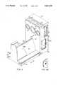
- FIG. 1is an end elevation view of a driver module according to the present invention
- FIG. 2is an axial sectional elevation view of the apparatus shown in FIG. 1 taken in the direction of arrows 2--2 of FIG. 1;
- FIG. 3Ais an end elevation view of a portion of a can processing apparatus assembled from modules according to the present invention, and including a left-hand module, a driver module, and a right-hand module;
- FIG. 3Bis an end elevation view of a left-hand module according to the present invention.
- FIG. 3Cis an end elevation view of a driver module according to the present invention.
- FIG. 3Dis an end elevation view of a right-hand module according to the present invention.
- FIG. 4is a perspective view of a driver module according to the present invention, including a headstock support portion connected to a tailstock support portion;
- FIG. 4Ais an enlarged view of a portion of a side interface surface on the headstock support portion of the driver module, showing a threaded attachment hole;
- FIG. 5is a perspective view of a right-hand module according to the present invention, including a headstock support portion connected to a tailstock support portion;
- FIG. 5Ais an enlarged view of a portion of a side interface surface on the headstock support portion of the right-hand module of FIG. 5 showing a threaded attachment hole;
- FIG. 6is a perspective view of a left-hand module according to the present invention, including a headstock support portion connected to a tailstock support portion;
- FIG. 6Ais an enlarged view of a portion of a side interface surface on the headstock support portion of the left-hand module shown in FIG. 6 showing a smooth bore attachment hole;
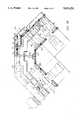
- FIG. 7is a perspective view of a right angle drive module according to the present invention.
- FIG. 7Ais a plan view in partial cross section, showing the right angle drive module of FIG. 7 connected to two additional modules;
- FIG. 8is a transverse sectional view, taken in the direction of arrows 8--8 in FIG. 4;
- FIG. 9is a transverse sectional view, taken in the direction of arrows 9--9 in FIG. 4;
- FIG. 10is a transverse sectional view, taken in the direction of arrows 10--10 in FIG. 5;
- FIG. 11is a transverse sectional view, taken in the direction of arrows 11--11 in FIG. 5;
- FIG. 12is a transverse sectional view, taken in the direction of arrows 12--12 in FIG. 6;
- FIG. 13is a transverse sectional view, taken in the direction of arrows 13--13 in FIG. 6.
- FIG. 2The general arrangement and structure of a can processing machine including the modular base of the present invention is best understood from FIG. 2. More specifically, a turret 20 is mounted on a spindle drive shaft 22 for rotation therewith in well known manner. A number of pairs of opposite, axially aligned spindle ram assemblies 24 and 26 are mounted on turret 20 at equally spaced intervals around the outer circumference of turret 20. Ram assemblies 24 and 26 each include a ram housing 28 and 30 respectively, rigidly fixed to turret 20, and a ram assembly 28a and 30a respectively, that is free to move axially within a respective ram housing 28 or 30.
- ram assembly 28a and/or ram assembly 30amay be provided with a coaxial, rotatably mounted tooling shaft that is free to rotate and may provide means for mounting can reshaping tools such as rollers for reforming the can bottom. Examples of such applications are shown in copending U.S. patent application Ser. Nos. 08/189,241, 08/189,243 and 08/268,812, which are herein incorporated by reference.
- One end of ram assembly 28aincludes a pair of cam rollers 32 and 34.
- one end of ram assembly 30aincludes a pair of cam rollers 36 and 38.
- First and second stationary cam members 40 and 42are respectively provided at opposite ends of the apparatus facing opposite axial ends of turret 20 with cam 40 having axially opposite contoured cam surfaces that engage with rollers 32 and 34; and cam 42 having axially opposite contoured cam surfaces that engage with cam rollers 36 and 38.
- Cam members 40 and 42are rigidly connected to a tailstock support portion (such as 50' in FIG. 4) of the modular base of the present invention, and a headstock support portion (such as 52' in FIG. 4) of the modular base of the present invention, respectively.
- Spindle drive shaft 22is rotatably mounted on tailstock support portion 50' and headstock support portion 52' of the driver module component 70 of the modular base of the present invention, as shown in FIG. 2.
- an identical spindle drive shaft 22is rotatably mounted on tailstock support portion 50" and headstock support portion 52" of a right hand drive module 82 (shown in FIG. 3D and FIG. 5), and on tailstock support portion 50" and headstock support portion 52" of a left hand drive module 80 (shown in FIG. 3B and FIG. 6).
- Driver module 70is generally the central module in a series of modules making up the modular base according to the present invention, as shown in FIG. 3A.
- Tailstock support portion 50' of driver module 70includes laterally extending leg portions 44 and 45 that provide a firm support base, as best shown in FIG. 4.
- a tailstock mounting portion 50aextends vertically at one axial end of tailstock support portion 50' and provides rotary support for one axial end of the spindle drive shaft 22, and fixed support for cam member 40.
- a tailstock connecting portion 50bhaving a substantially triangular cross section, extends axially from mounting portion 50a and terminates in a transverse interface portion 51a.
- Transverse interface portion 51amates with corresponding, axially spaced, transverse interface portion 51b on headstock support portion 52' through a pattern of bolt holes and/or dowel pin holes, as best seen in FIGS. 8 and 9.
- the axial end of spindle drive shaft 22 opposite from the end supported on tailstock mounting portion 50apasses through a locating hole 54 on headstock support portion 52' and is rotatably mounted by bearings or bushings supported by headstock support portion 52'.
- Locating holes 55 through headstock support portion 52' on laterally opposite sides of locating hole 54provide location and support for cantilevered transfer drive shafts 60 (shown in FIG. 3A) supported by headstock support portion 52'.
- Cantilevered transfer drive shafts 60carry can transfer pockets 62 that transfer cans to and from can support pockets 64 mounted on spindle drive shaft 22.
- Right hand module 82shown in FIG. 5, is similar to driver module 70, except that tailstock support portion 50" has only one laterally extending leg 46 on one side of spindle drive shaft 22, and only one locating hole 55 in headstock support portion 52" for a cantilevered transfer drive shaft 60.
- Left hand module 80shown in FIG. 6, is essentially a mirror image of right hand module 82, with laterally extending leg 47 of tailstock support portion 50'" and locating hole 55 in headstock support portion 52" being on the opposite side of spindle drive shaft 22 from that of right hand module 82.
- a driver module 70includes two such transfer drive shafts 60, one mounted on each side of spindle drive shaft 22.
- Each transfer drive shaft 60supports a plurality of circumferentially spaced can transfer pockets 62, in an arrangement commonly referred to as a "star wheel", such as shown in copending U.S. patent application No. 08/189,241, which is herein incorporated by reference.
- Can transfer pockets 62are rigidly connected to transfer drive shaft 60, and rotate therewith as transfer drive shaft 60 is rotated by a driven gear (not shown) that engages with driver gear 72 mounted on a first end of spindle drive shaft 22.
- Spindle drive shaft 22 and turret 20 of each moduleare also connected to a plurality of circumferentially spaced can support pockets 64 which are positioned so as to support cans for processing in between axially aligned ram housings 28 and 30.
- Individual can support pockets 64can be bolted to turret 20, such as shown in copending U.S. patent application entitled “Improved Can Feed And Work Station” filed on Mar. 8, 1995 under attorney docket number 18493.047 (serial no. not yet assigned), which is herein incorporated by reference.
- Can transfer pockets 62 mounted on transfer drive shaft 60 and can support pockets 64 mounted on spindle drive shaft 22are positioned relative to each other such that as spindle drive shaft 22 and transfer drive shaft 60 are rotated, cans are transferred directly from can support pockets 64 on spindle drive shaft 22 to can transfer pockets 62 on transfer drive shaft 60.
- Driver module 70includes spindle drive shaft 22 and two transfer drive shafts 60, one on each side of spindle drive shaft 22.
- a motor 84, or other means for rotating spindle drive shaft 22,is mounted on the headstock support portion 52' of driver module 70.
- Left-hand module 80has only one transfer drive shaft 60 mounted on the left side of spindle drive shaft 22, as viewed from the axial end of spindle drive shaft 22 that is supported by tailstock mounting portion 50f of tailstock support portion 50'", as shown in FIG. 3B and FIG. 6.
- Right-hand module 82as shown in FIG. 3D and FIG. 5, has only one transfer drive shaft 60 mounted on the right-hand side of spindle drive shaft 22 as viewed from the axial end of spindle drive shaft 22 that is supported by tailstock mounting portion 50d of tailstock support portion 50".
- Left-hand module 80, right-hand module 82, and driver module 70are each provided with side interface surfaces 80a, 82a, and 70a, respectively, such that the individual modules can be readily connected in side-by-side relationship.
- Side interface surfaces 70a, 80a, and 82aare each provided with a pattern of bolt holes 86 and a key/keyway 91, as shown in FIGS. 4, 4A, 5 and 5A, for alignment and interconnection of the modules.
- spindle drive shaft 22 and can support pockets 64 of each moduleare spaced from transfer drive shaft 60 and can transfer pockets 62 of an adjacent module such that when spindle drive shaft 22 of one module is rotated and transfer drive shaft 60 of an adjacent module is rotated, a can is transferred directly from can support pockets 64 on spindle drive shaft 22 of the one module to can transfer pockets 62 on transfer drive shaft 60 of the adjacent module.
- additional left-hand modules 80, right-hand modules 82, driver modules 70, or right-angle transfer modules 90(as shown in FIG. 7), can be easily connected at their respective side interface surfaces to the existing modular can processing equipment.
- Right angle transfer modules 90allow for the transfer of cans around corners, thereby providing flexibility in processing machine layout and conservation of existing floor space in the manufacturing facility.
- Right angle transfer module 90includes an upper gearbox portion 94 that is subdivided into a continuous gear chamber 95, and a connecting vacuum chamber 92. Right angle transfer module 90 is further subdivided into a continuous vacuum chamber 57 that allows for the transfer of vacuum to connecting vacuum chamber 92, and then through radial and axial passageways through spindle drive shaft 22 and/or transfer drive shafts 60 to points of application.
- Gear chamber 95 located in upper gearbox portion 94houses a plurality of gears 96 mounted on parallel shafts 97 extending across gear chamber 95 in spaced relationship such that gears 96 are meshingly engaged in series.
- the outer parallel shafts 97 mounted at both sides of module 90support bevel gears 98 mounted in tandem with gears 96.
- Bevel gears 98engage with additional bevel gears 99 mounted on cantilevered ends of transfer drive shafts 60 that extend into gear chamber 95 at opposite sides of module 90.
- a spindle drive shaft 22is connected to a driver gear 72 that forms the central gear in the series of gears 96.
- Driver gear 72can be connected to a driving means such as an electric motor if it is desired to use right angle transfer module 90 as a driver module.
- Transfer drive shafts 60 supported at both sides of right angle transfer module 90are oriented at approximately 45 degrees to spindle drive shaft 22 supported at the center of right angle transfer module 90.
- Special beveled can support pockets 164are mounted on the end of spindle drive shaft 22 opposite from driver gear 72; and can transfer pockets 162 are mounted on the ends of transfer drive shafts 60 opposite from bevel gears 99.
- Beveled can support pockets 164are designed and located so as to be able to pass cans directly to can transfer pockets 162, effecting a 45 degree change in orientation of the central axes of the cans.
- the right angle transfer module with can transfer pockets 162 mounted on opposite sides of special beveled can support pockets 164therefore results in a 90 degree change in orientation of the central axis of cans that are handled by the right angle transfer module 90.
- Each module 70, 80, 82 and 90is preferably constructed from a ductile cast iron.
- Modules 70, 80 and 82each consist of a substantially rectangular headstock support portion 52', 52" or 52'" and a tailstock support portion 50', 50" or 50'".
- Right angle transfer module 90includes a headstock support portion 90', shown in FIG. 7, having side portions that are at an angle relative to a central, rectangular portion, such that the side portions support transfer drive shafts 60 at an angle relative to central spindle drive shaft 22 supported by the central rectangular portion.
- Headstock support portions 52', 52", 52'" and 90'each have an upper gearbox portion 53', 53", 53'" or 94, respectively, forming a continuous gear chamber when a plurality of modules are connected together in side-by-side relationship, and having axial through-holes 54 and 55 which provide clearance and/or location surfaces for rotatably supporting spindle drive shaft 22 and transfer drive shafts 60, respectively.
- Headstock support portions 52', 52", 52" and 94are each subdivided into internal chambers separated by internal walls 56.
- a vacuum chamber 57is formed in the headstock support portion below the upper gearbox portion.
- Connecting vacuum chambers 92provide an interconnection between main vacuum chambers 57 and spindle drive shaft 22 and/or transfer drive shaft 60.
- Vacuum chamber 57is connected through openings through internal walls 56, connecting vacuum chambers 92, and axial and radial passageways through spindle drive shaft 22 or transfer drive shaft 60 to openings in can support pockets 64 or can transfer pockets 62, respectively, when vacuum is desired to help hold cans in place on can support pockets 64 during processing or on can transfer pockets 62 during transfer.
- a high pressure air passageway 58, and a low pressure air passageway 59can be provided through internal walls 56 in the upper gearbox portion of a respective headstock support portion. Air passageways 58 and 59 provide pressurized air for can processing, and eliminate the need for separate air lines running to each can processing station.
- gasketscan be provided around vacuum chambers 57 and air passageways 58 and 59 in order to ensure a leak-tight fit.
- a seal platecan be provided over the ends of vacuum chamber 57 in that one module, thereby confining the vacuum created by a vacuum pump (not shown) to that single module. If vacuum is desired in a number of adjacent modules, the seal plate is eliminated and open gaskets are provided between the vacuum chambers 57 in adjacent modules.
- upper gearbox portions 53', 53", 53'" and 94 of headstock support portions 52', 52", 52'" and 90'respectively, also provide clearance for driver gears 72 and driven gears (such as 96 in right angle transfer module 90) which are fixed at one axial end of each spindle drive shaft 22 and transfer drive shaft 60.
- the driver gears and driven gears of adjacent modulesare engaged such that, for example, rotation of the spindle drive shaft 22 of driver module 70, having driver gear 72 and motor 84 mounted thereon, is transferred in series to successive transfer drive shafts and spindle drive shafts mounted in adjacent modules extending to the left and to the right of a center driver module 70.
- Direct engagement between gears that are rigidly attached to spindle drive shafts 22 and transfer drive shafts 60is enabled by the open communication between gear chambers in the upper gearbox portions of adjacent modules. This direct engagement ensures that rotation of can support pockets 64 will always be in synch with rotation of can transfer pockets 62.
- Tailstock support portion 50', 50" or 50'The end of spindle drive shafts 22 and transfer drive shafts 60 opposite from the driving or driven ends of each of said shafts is supported on a tailstock support portion 50', 50" or 50'", as best shown in FIG. 2.
- Tailstock support portion 50', of driver module 70is subdivided into a mounting portion 50a and a connecting portion 50b, as shown in FIG. 4.
- Tailstock support portion 50', of right hand module 82is subdivided into a mounting portion 50d and a connecting portion 50e, as shown in FIG. 5.
- Tailstock support portion 50'" of left hand module 80is subdivided into a mounting portion 50f and a connecting portion 50g, as shown in FIG. 6.
- Tailstock connecting portions 50b, of driver module 70, 50e of right hand module 82 and 50g of left hand module 80are substantially triangular in cross-section and extend axially from mounting portions 50a, 50d and 50f, respectively, to a transverse interfacing portion 51a, 51c or 51e, respectively, that connects to headstock support portion 52', 52" or 52'", respectively.
- Mating surface 51b of headstock support portion 52', mating surface 51d of headstock support portion 52", mating surface 51f of headstock support portion 52'" and corresponding axially spaced transverse interfacing portions 51a, 51c and 51e on respective tailstock support portionsare ground fiat as shown in FIGS. 8-13, and are provided with the pattern of bolt holes and dowel pin holes as shown.
- the angled internal wall 50c between the mounting portion of a tailstock support portion and a tailstock connecting portionis provided for additional strength and ease of manufacture of the tailstock support portion.
- the shape of the tailstock support portions and the headstock support portionscan be varied as long as there is consistency in size for any particular line of modules, and the modules are sized such that the spindle drive shafts and transfer drive shafts of adjacent modules will be supported at the correct lateral distance from each other for direct transfer of cans being processed.
Landscapes
- Engineering & Computer Science (AREA)
- Mechanical Engineering (AREA)
- Automation & Control Theory (AREA)
- Specific Conveyance Elements (AREA)
- Devices For Medical Bathing And Washing (AREA)
- Control And Other Processes For Unpacking Of Materials (AREA)
- Making Paper Articles (AREA)
- Cleaning Implements For Floors, Carpets, Furniture, Walls, And The Like (AREA)
- Chain Conveyers (AREA)
- Filling Of Jars Or Cans And Processes For Cleaning And Sealing Jars (AREA)
- Cartons (AREA)
- Auxiliary Devices For And Details Of Packaging Control (AREA)
- Supplying Of Containers To The Packaging Station (AREA)
- Blow-Moulding Or Thermoforming Of Plastics Or The Like (AREA)
- Massaging Devices (AREA)
Abstract
Description
Claims (18)
Priority Applications (16)
| Application Number | Priority Date | Filing Date | Title |
|---|---|---|---|
| US08/426,122US5611231A (en) | 1995-04-20 | 1995-04-20 | Modular base can processing equipment |
| AU53615/96AAU693345B2 (en) | 1995-04-20 | 1996-03-18 | Modular base can processing equipment |
| BR9606332-7ABR9606332A (en) | 1995-04-20 | 1996-03-18 | Modular base for can processing equipment support |
| CA002193631ACA2193631A1 (en) | 1995-04-20 | 1996-03-18 | Modular base can processing equipment |
| DE69608061TDE69608061T2 (en) | 1995-04-20 | 1996-03-18 | MODULAR DEVICE FOR WORKING CONTAINERS |
| JP8531721AJPH09512750A (en) | 1995-04-20 | 1996-03-18 | Module base for can processing equipment |
| AT96910419TATE192366T1 (en) | 1995-04-20 | 1996-03-18 | MODULAR DEVICE FOR PROCESSING CONTAINERS |
| CZ963727ACZ372796A3 (en) | 1995-04-20 | 1996-03-18 | Modular base of apparatus for producing cans |
| HU9603520AHUP9603520A3 (en) | 1995-04-20 | 1996-03-18 | Modular base can processing equipment |
| PCT/US1996/003297WO1996033032A1 (en) | 1995-04-20 | 1996-03-18 | Modular base can processing equipment |
| EP96910419AEP0767713B1 (en) | 1995-04-20 | 1996-03-18 | Modular base can processing equipment |
| RO96-02434ARO113009B1 (en) | 1995-04-20 | 1996-03-18 | CYLINDRICAL RECIPIENT MACHINE |
| PL96317867APL317867A1 (en) | 1995-04-20 | 1996-03-18 | Modular apparatus for processing containers |
| NZ305579ANZ305579A (en) | 1995-04-20 | 1996-03-18 | Modular base typically for supporting can processing equipment with modules supporting shafts and having interconnectable chambers |
| NO965451ANO965451L (en) | 1995-04-20 | 1996-12-18 | Modular box processing equipment |
| FI965108AFI965108A7 (en) | 1995-04-20 | 1996-12-19 | Modular can handling equipment |
Applications Claiming Priority (1)
| Application Number | Priority Date | Filing Date | Title |
|---|---|---|---|
| US08/426,122US5611231A (en) | 1995-04-20 | 1995-04-20 | Modular base can processing equipment |
Publications (1)
| Publication Number | Publication Date |
|---|---|
| US5611231Atrue US5611231A (en) | 1997-03-18 |
Family
ID=23689399
Family Applications (1)
| Application Number | Title | Priority Date | Filing Date |
|---|---|---|---|
| US08/426,122Expired - LifetimeUS5611231A (en) | 1995-04-20 | 1995-04-20 | Modular base can processing equipment |
Country Status (16)
| Country | Link |
|---|---|
| US (1) | US5611231A (en) |
| EP (1) | EP0767713B1 (en) |
| JP (1) | JPH09512750A (en) |
| AT (1) | ATE192366T1 (en) |
| AU (1) | AU693345B2 (en) |
| BR (1) | BR9606332A (en) |
| CA (1) | CA2193631A1 (en) |
| CZ (1) | CZ372796A3 (en) |
| DE (1) | DE69608061T2 (en) |
| FI (1) | FI965108A7 (en) |
| HU (1) | HUP9603520A3 (en) |
| NO (1) | NO965451L (en) |
| NZ (1) | NZ305579A (en) |
| PL (1) | PL317867A1 (en) |
| RO (1) | RO113009B1 (en) |
| WO (1) | WO1996033032A1 (en) |
Cited By (29)
| Publication number | Priority date | Publication date | Assignee | Title |
|---|---|---|---|---|
| US5785294A (en)* | 1995-05-10 | 1998-07-28 | Coors Brewing Company | Necking apparatus support |
| EP0965398A1 (en)* | 1998-06-18 | 1999-12-22 | Hans Kordyla | System for manufacturing workpieces, in particular closure caps for containers |
| WO2000023212A1 (en)* | 1998-10-22 | 2000-04-27 | Crown Cork & Seal Technologies Corporation | Method and apparatus for closely coupling machines used for can making |
| US6178797B1 (en) | 1999-06-25 | 2001-01-30 | Delaware Capital Formation, Inc. | Linking apparatus and method for a can shaping system |
| US6698265B1 (en)* | 2002-09-06 | 2004-03-02 | Crown Cork & Seal Technologies Corporation | Method for closely coupling machines used for can making |
| US20040050668A1 (en)* | 2002-09-16 | 2004-03-18 | Delaware Capital Formation, Inc. | Link system |
| US20040165802A1 (en)* | 2003-02-24 | 2004-08-26 | Delaware Capital Formation, Inc. | Bearing locking mechanism |
| ES2222843A1 (en)* | 2004-05-21 | 2005-02-01 | Mobemur, S.L. | Seaming machine for preserved cans, has sockets provided on periphery of disks, and gateway, exit part and feeder lid connected to disks, where width of gateway and exit part is greater than that of sockets |
| US20060101885A1 (en)* | 2004-11-18 | 2006-05-18 | Delaware Capital Formation, Inc. | Quick change over apparatus for machine line |
| US20090266129A1 (en)* | 2008-04-24 | 2009-10-29 | Daniel Egerton | Container manufacturing process having front-end winder assembly |
| US20090266128A1 (en)* | 2008-04-24 | 2009-10-29 | Crown Packaging Technology, Inc. | Apparatus for rotating a container body |
| US20090266126A1 (en)* | 2008-04-24 | 2009-10-29 | Crown Packaging Technology, Inc. | Systems and methods for monitoring and controlling a can necking process |
| US20090266131A1 (en)* | 2008-04-24 | 2009-10-29 | Crown Packaging Technology, Inc. | High Speed Necking Configuration |
| US20100095725A1 (en)* | 2008-10-20 | 2010-04-22 | Crown Packaging Technology, Inc. | Bridge turret transfer assembly |
| US20100212385A1 (en)* | 2009-02-26 | 2010-08-26 | Belvac Production Machinery, Inc. | Quick change for transfer starwheel |
| CN101164716B (en)* | 2006-08-09 | 2011-08-24 | 弗拉蒂尼建筑机械公开有限公司 | Apparatus for forming metal container by electric coordinating device |
| US8245551B2 (en) | 2008-04-24 | 2012-08-21 | Crown Packaging Technology, Inc. | Adjustable transfer assembly for container manufacturing process |
| US8464567B2 (en) | 2008-04-24 | 2013-06-18 | Crown Packaging Technology, Inc. | Distributed drives for a multi-stage can necking machine |
| US9878365B2 (en) | 2013-11-22 | 2018-01-30 | Silgan Containers Llc | Can-making apparatus with trimmer chute |
| US10391541B2 (en) | 2014-02-27 | 2019-08-27 | Belvac Production Machinery, Inc. | Recirculation systems and methods for can and bottle making machinery |
| US10934104B2 (en) | 2018-05-11 | 2021-03-02 | Stolle Machinery Company, Llc | Infeed assembly quick change features |
| CN112839751A (en)* | 2018-10-11 | 2021-05-25 | 贝瓦克生产机械有限公司 | Universal base for can necking systems |
| US11097333B2 (en) | 2018-05-11 | 2021-08-24 | Stolle Machinery Company, Llc | Process shaft tooling assembly |
| US11117180B2 (en) | 2018-05-11 | 2021-09-14 | Stolle Machinery Company, Llc | Quick change tooling assembly |
| US11208271B2 (en) | 2018-05-11 | 2021-12-28 | Stolle Machinery Company, Llc | Quick change transfer assembly |
| US11370015B2 (en)* | 2018-05-11 | 2022-06-28 | Stolle Machinery Company, Llc | Drive assembly |
| US11420242B2 (en) | 2019-08-16 | 2022-08-23 | Stolle Machinery Company, Llc | Reformer assembly |
| US11534817B2 (en) | 2018-05-11 | 2022-12-27 | Stolle Machinery Company, Llc | Infeed assembly full inspection assembly |
| US11565303B2 (en) | 2018-05-11 | 2023-01-31 | Stolle Machinery Company, Llc | Rotary manifold |
Families Citing this family (8)
| Publication number | Priority date | Publication date | Assignee | Title |
|---|---|---|---|---|
| US7464573B2 (en) | 2006-03-31 | 2008-12-16 | Belvac Production Machinery, Inc. | Apparatus for curling an article |
| US7905130B2 (en) | 2006-03-31 | 2011-03-15 | Belvac Production Machinery, Inc. | Apparatus for threading cans |
| US7530445B2 (en) | 2006-03-31 | 2009-05-12 | Belvac Production Machinery, Inc. | Long stroke slide assemblies |
| US7963139B2 (en) | 2006-03-31 | 2011-06-21 | Belvac Production Machinery, Inc. | Apparatus for can expansion |
| US7886894B2 (en) | 2006-03-31 | 2011-02-15 | Belvac Production Machinery, Inc. | Method and apparatus for bottle recirculation |
| US7818987B2 (en) | 2006-03-31 | 2010-10-26 | Belvac Production Machinery, Inc. | Method and apparatus for trimming a can |
| US8653984B2 (en) | 2008-10-24 | 2014-02-18 | Ilumisys, Inc. | Integration of LED lighting control with emergency notification systems |
| JP2023163407A (en)* | 2022-04-28 | 2023-11-10 | 東洋製罐グループホールディングス株式会社 | Can body production system and method for producing can body |
Citations (3)
| Publication number | Priority date | Publication date | Assignee | Title |
|---|---|---|---|---|
| US2467278A (en)* | 1942-07-14 | 1949-04-12 | Fmc Corp | Machine for packing string beans |
| US2550156A (en)* | 1944-10-04 | 1951-04-24 | Package Machinery Co | Interchangeable conveyer frame units |
| US4519232A (en)* | 1982-12-27 | 1985-05-28 | National Can Corporation | Method and apparatus for necking containers |
Family Cites Families (3)
| Publication number | Priority date | Publication date | Assignee | Title |
|---|---|---|---|---|
| US3610009A (en)* | 1969-10-23 | 1971-10-05 | Metal Box Co Ltd | Flanging thin metal cylinders |
| US3687098A (en)* | 1971-03-19 | 1972-08-29 | Coors Porcelain Co | Container necking mechanism and method |
| US4513595A (en)* | 1982-02-08 | 1985-04-30 | Cvacho Daniel S | Methods of necking-in and flanging tubular can bodies |
- 1995
- 1995-04-20USUS08/426,122patent/US5611231A/ennot_activeExpired - Lifetime
- 1996
- 1996-03-18BRBR9606332-7Apatent/BR9606332A/enunknown
- 1996-03-18HUHU9603520Apatent/HUP9603520A3/enunknown
- 1996-03-18EPEP96910419Apatent/EP0767713B1/ennot_activeExpired - Lifetime
- 1996-03-18PLPL96317867Apatent/PL317867A1/enunknown
- 1996-03-18DEDE69608061Tpatent/DE69608061T2/ennot_activeExpired - Fee Related
- 1996-03-18AUAU53615/96Apatent/AU693345B2/ennot_activeCeased
- 1996-03-18CZCZ963727Apatent/CZ372796A3/enunknown
- 1996-03-18NZNZ305579Apatent/NZ305579A/enunknown
- 1996-03-18CACA002193631Apatent/CA2193631A1/ennot_activeAbandoned
- 1996-03-18WOPCT/US1996/003297patent/WO1996033032A1/ennot_activeApplication Discontinuation
- 1996-03-18JPJP8531721Apatent/JPH09512750A/enactivePending
- 1996-03-18RORO96-02434Apatent/RO113009B1/enunknown
- 1996-03-18ATAT96910419Tpatent/ATE192366T1/ennot_activeIP Right Cessation
- 1996-12-18NONO965451Apatent/NO965451L/enunknown
- 1996-12-19FIFI965108Apatent/FI965108A7/enunknown
Patent Citations (3)
| Publication number | Priority date | Publication date | Assignee | Title |
|---|---|---|---|---|
| US2467278A (en)* | 1942-07-14 | 1949-04-12 | Fmc Corp | Machine for packing string beans |
| US2550156A (en)* | 1944-10-04 | 1951-04-24 | Package Machinery Co | Interchangeable conveyer frame units |
| US4519232A (en)* | 1982-12-27 | 1985-05-28 | National Can Corporation | Method and apparatus for necking containers |
Cited By (71)
| Publication number | Priority date | Publication date | Assignee | Title |
|---|---|---|---|---|
| US5785294A (en)* | 1995-05-10 | 1998-07-28 | Coors Brewing Company | Necking apparatus support |
| US6257544B1 (en)* | 1995-05-10 | 2001-07-10 | Coors Brewing Company | Necking apparatus support |
| EP0965398A1 (en)* | 1998-06-18 | 1999-12-22 | Hans Kordyla | System for manufacturing workpieces, in particular closure caps for containers |
| WO2000023212A1 (en)* | 1998-10-22 | 2000-04-27 | Crown Cork & Seal Technologies Corporation | Method and apparatus for closely coupling machines used for can making |
| US6085563A (en)* | 1998-10-22 | 2000-07-11 | Crown Cork & Seal Technologies Corporation | Method and apparatus for closely coupling machines used for can making |
| US6240760B1 (en) | 1998-10-22 | 2001-06-05 | Crown Cork & Seal Technologies Corporation | Method and apparatus for closely coupling machines used for can making |
| US6178797B1 (en) | 1999-06-25 | 2001-01-30 | Delaware Capital Formation, Inc. | Linking apparatus and method for a can shaping system |
| US6698265B1 (en)* | 2002-09-06 | 2004-03-02 | Crown Cork & Seal Technologies Corporation | Method for closely coupling machines used for can making |
| US6886682B2 (en) | 2002-09-16 | 2005-05-03 | Delaware Capital Formation Inc. | Link system |
| WO2004025167A1 (en)* | 2002-09-16 | 2004-03-25 | Delaware Capital Formation, Inc. | Link system |
| US20040050668A1 (en)* | 2002-09-16 | 2004-03-18 | Delaware Capital Formation, Inc. | Link system |
| US20040165802A1 (en)* | 2003-02-24 | 2004-08-26 | Delaware Capital Formation, Inc. | Bearing locking mechanism |
| US6905249B2 (en) | 2003-02-24 | 2005-06-14 | Delaware Capital Formation, Inc. | Bearing locking mechanism |
| ES2222843A1 (en)* | 2004-05-21 | 2005-02-01 | Mobemur, S.L. | Seaming machine for preserved cans, has sockets provided on periphery of disks, and gateway, exit part and feeder lid connected to disks, where width of gateway and exit part is greater than that of sockets |
| ES2222843B2 (en)* | 2004-05-21 | 2005-08-16 | Mobemur, S.L. | CLOSURE MACHINE FOR CANNED AND SIMILAR BOATS. |
| US20060104745A1 (en)* | 2004-11-18 | 2006-05-18 | Delaware Capital Formation, Inc. | Quick change over apparatus for machine line |
| US20060101884A1 (en)* | 2004-11-18 | 2006-05-18 | Delaware Capital Formation, Inc. | Quick change over apparatus for machine line |
| US20060101885A1 (en)* | 2004-11-18 | 2006-05-18 | Delaware Capital Formation, Inc. | Quick change over apparatus for machine line |
| US20060101889A1 (en)* | 2004-11-18 | 2006-05-18 | Delaware Capital Formation, Inc. | Quick change over apparatus for machine line |
| US7310983B2 (en) | 2004-11-18 | 2007-12-25 | Belvac Production Machinery, Inc. | Quick change over apparatus for machine line |
| US7387007B2 (en) | 2004-11-18 | 2008-06-17 | Belvac Production Machinery, Inc. | Quick change over apparatus for machine line |
| US7404309B2 (en) | 2004-11-18 | 2008-07-29 | Belvac Production Machinery, Inc. | Quick change over apparatus for machine line |
| US7409845B2 (en) | 2004-11-18 | 2008-08-12 | Belvac Production Machinery, Inc. | Quick change over apparatus for machine line |
| US7418852B2 (en) | 2004-11-18 | 2008-09-02 | Belvac Production Machinery, Inc. | Quick change over apparatus for machine line |
| US7454944B2 (en) | 2004-11-18 | 2008-11-25 | Belvac Production Machinery, Inc. | Quick change over apparatus for machine line |
| CN101164716B (en)* | 2006-08-09 | 2011-08-24 | 弗拉蒂尼建筑机械公开有限公司 | Apparatus for forming metal container by electric coordinating device |
| US9308570B2 (en) | 2008-04-24 | 2016-04-12 | Crown Packaging Technology, Inc. | High speed necking configuration |
| US20090266129A1 (en)* | 2008-04-24 | 2009-10-29 | Daniel Egerton | Container manufacturing process having front-end winder assembly |
| US20090266131A1 (en)* | 2008-04-24 | 2009-10-29 | Crown Packaging Technology, Inc. | High Speed Necking Configuration |
| US8464567B2 (en) | 2008-04-24 | 2013-06-18 | Crown Packaging Technology, Inc. | Distributed drives for a multi-stage can necking machine |
| US7770425B2 (en) | 2008-04-24 | 2010-08-10 | Crown, Packaging Technology, Inc. | Container manufacturing process having front-end winder assembly |
| US10751784B2 (en) | 2008-04-24 | 2020-08-25 | Crown Packaging Technology, Inc. | High speed necking configuration |
| US9968982B2 (en) | 2008-04-24 | 2018-05-15 | Crown Packaging Technology, Inc. | High speed necking configuration |
| US8245551B2 (en) | 2008-04-24 | 2012-08-21 | Crown Packaging Technology, Inc. | Adjustable transfer assembly for container manufacturing process |
| US9290329B2 (en) | 2008-04-24 | 2016-03-22 | Crown Packaging Technology, Inc. | Adjustable transfer assembly for container manufacturing process |
| US20090266126A1 (en)* | 2008-04-24 | 2009-10-29 | Crown Packaging Technology, Inc. | Systems and methods for monitoring and controlling a can necking process |
| US8601843B2 (en) | 2008-04-24 | 2013-12-10 | Crown Packaging Technology, Inc. | High speed necking configuration |
| US7784319B2 (en) | 2008-04-24 | 2010-08-31 | Crown, Packaging Technology, Inc | Systems and methods for monitoring and controlling a can necking process |
| US7997111B2 (en) | 2008-04-24 | 2011-08-16 | Crown, Packaging Technology, Inc. | Apparatus for rotating a container body |
| US20090266128A1 (en)* | 2008-04-24 | 2009-10-29 | Crown Packaging Technology, Inc. | Apparatus for rotating a container body |
| US8375759B2 (en) | 2008-10-20 | 2013-02-19 | Crown Packaging Technology, Inc. | Bridge turret transfer assembly |
| US20100095725A1 (en)* | 2008-10-20 | 2010-04-22 | Crown Packaging Technology, Inc. | Bridge turret transfer assembly |
| US8733146B2 (en)* | 2009-02-26 | 2014-05-27 | Belvac Production Machinery, Inc. | Can processing machine with cantilever design |
| US20100212390A1 (en)* | 2009-02-26 | 2010-08-26 | Belvac Production Machinery, Inc. | Dual ram for necker machine |
| US8464836B2 (en) | 2009-02-26 | 2013-06-18 | Belvac Production Machinery, Inc. | Lubrication applicator for can processing machine |
| US8297098B2 (en) | 2009-02-26 | 2012-10-30 | Belvac Production Machinery, Inc. | Dual ram assembly for necker machine |
| US20100212394A1 (en)* | 2009-02-26 | 2010-08-26 | Belvac Production Machinery, Inc. | Can processing machine with cantilever design |
| US8616559B2 (en) | 2009-02-26 | 2013-12-31 | Belvac Production Machinery, Inc. | Key for quick change for turret pocket |
| US8627705B2 (en) | 2009-02-26 | 2014-01-14 | Belvac Production Machinery, Inc. | Self compensating sliding air valve mechanism |
| US8464856B2 (en) | 2009-02-26 | 2013-06-18 | Belvac Production Machinery, Inc. | Quick change for transfer starwheel |
| US9095888B2 (en) | 2009-02-26 | 2015-08-04 | Belvac Production Machinery, Inc. | Can processing machine with cantilever design |
| US20100213030A1 (en)* | 2009-02-26 | 2010-08-26 | Belvac Production Machinery, Inc. | Lubrication applicator for can processing machine |
| US20100213677A1 (en)* | 2009-02-26 | 2010-08-26 | Belvac Production Machinery, Inc. | Key for quick change for turret pocket |
| US20100212385A1 (en)* | 2009-02-26 | 2010-08-26 | Belvac Production Machinery, Inc. | Quick change for transfer starwheel |
| US20100212130A1 (en)* | 2009-02-26 | 2010-08-26 | Belvac Production Machinery, Inc. | Self compensating sliding air valve mechanism |
| US9878365B2 (en) | 2013-11-22 | 2018-01-30 | Silgan Containers Llc | Can-making apparatus with trimmer chute |
| US10391541B2 (en) | 2014-02-27 | 2019-08-27 | Belvac Production Machinery, Inc. | Recirculation systems and methods for can and bottle making machinery |
| US10934104B2 (en) | 2018-05-11 | 2021-03-02 | Stolle Machinery Company, Llc | Infeed assembly quick change features |
| US11534817B2 (en) | 2018-05-11 | 2022-12-27 | Stolle Machinery Company, Llc | Infeed assembly full inspection assembly |
| US11097333B2 (en) | 2018-05-11 | 2021-08-24 | Stolle Machinery Company, Llc | Process shaft tooling assembly |
| US11117180B2 (en) | 2018-05-11 | 2021-09-14 | Stolle Machinery Company, Llc | Quick change tooling assembly |
| US11890664B2 (en)* | 2018-05-11 | 2024-02-06 | Stolle Machinery Company, Llc | Drive assembly |
| US11208271B2 (en) | 2018-05-11 | 2021-12-28 | Stolle Machinery Company, Llc | Quick change transfer assembly |
| US11370015B2 (en)* | 2018-05-11 | 2022-06-28 | Stolle Machinery Company, Llc | Drive assembly |
| US11565303B2 (en) | 2018-05-11 | 2023-01-31 | Stolle Machinery Company, Llc | Rotary manifold |
| US20220274154A1 (en)* | 2018-05-11 | 2022-09-01 | Stolle Machinery Company, Llc | Drive assembly |
| US20210354192A1 (en)* | 2018-10-11 | 2021-11-18 | Belvac Production Machinery, Inc. | Versatile base for can necking system |
| CN112839751B (en)* | 2018-10-11 | 2023-02-28 | 贝瓦克生产机械有限公司 | Universal base for tank necking systems |
| CN112839751A (en)* | 2018-10-11 | 2021-05-25 | 贝瓦克生产机械有限公司 | Universal base for can necking systems |
| US12030107B2 (en)* | 2018-10-11 | 2024-07-09 | Belvac Production Machinery, Inc. | Versatile base for can necking system |
| US11420242B2 (en) | 2019-08-16 | 2022-08-23 | Stolle Machinery Company, Llc | Reformer assembly |
Also Published As
| Publication number | Publication date |
|---|---|
| FI965108A0 (en) | 1996-12-19 |
| BR9606332A (en) | 2002-12-17 |
| EP0767713A1 (en) | 1997-04-16 |
| JPH09512750A (en) | 1997-12-22 |
| EP0767713B1 (en) | 2000-05-03 |
| EP0767713A4 (en) | 1997-06-11 |
| CZ372796A3 (en) | 1999-10-13 |
| HUP9603520A3 (en) | 1998-11-30 |
| WO1996033032A1 (en) | 1996-10-24 |
| AU693345B2 (en) | 1998-06-25 |
| AU5361596A (en) | 1996-11-07 |
| ATE192366T1 (en) | 2000-05-15 |
| NO965451L (en) | 1997-02-07 |
| RO113009B1 (en) | 1998-03-30 |
| NZ305579A (en) | 1997-10-24 |
| FI965108A7 (en) | 1997-02-17 |
| DE69608061D1 (en) | 2000-06-08 |
| CA2193631A1 (en) | 1996-10-24 |
| NO965451D0 (en) | 1996-12-18 |
| HUP9603520A2 (en) | 1997-10-28 |
| PL317867A1 (en) | 1997-04-28 |
| DE69608061T2 (en) | 2000-09-07 |
Similar Documents
| Publication | Publication Date | Title |
|---|---|---|
| US5611231A (en) | Modular base can processing equipment | |
| WO1996033032A9 (en) | Modular base can processing equipment | |
| US4732027A (en) | Method and apparatus for necking and flanging containers | |
| US20050193796A1 (en) | Apparatus for necking a can body | |
| EP2401095B1 (en) | Can processing machine with cantilever design | |
| US5768931A (en) | Article processing machine | |
| US6178797B1 (en) | Linking apparatus and method for a can shaping system | |
| EP0438988B1 (en) | A system for welding together pressed sheet-metal structures, particularly small subassemblies of the bodywork or mechanical parts of motor vehicles | |
| US20240359229A1 (en) | Versatile base for can necking system | |
| JPS6366623B2 (en) | ||
| GB2264254A (en) | Transporting apparatus | |
| KR0119644B1 (en) | Phase matching method and apparatus of rotating body | |
| JP3188364B2 (en) | Progressive die machine | |
| CN117960476A (en) | Be used for multiple type sheet metal component spraying assembly line | |
| MXPA96006740A (en) | Basemodu can container processing equipment | |
| SU1292660A3 (en) | Set for manufacturing seamless rings | |
| US4238875A (en) | Method of and apparatus for performing work functions on articles from opposite ends of the articles | |
| JPH09323198A (en) | Pressing machine for aluminum sash | |
| CN217797924U (en) | Servo-driven rotary tool platform | |
| CN113523314B (en) | Processing technology and processing system for triple gear | |
| US5031306A (en) | Assembly turret with universal nests | |
| CN219928678U (en) | Workpiece conveying system and workpiece automatic processing and forming system | |
| CN215547076U (en) | Chain conveying and positioning device | |
| JP2000271796A (en) | Processing method of transfer press line | |
| CN115781419A (en) | Aluminum alloy profile production and processing device and processing method |
Legal Events
| Date | Code | Title | Description |
|---|---|---|---|
| AS | Assignment | Owner name:BELVAC PRODUCTION MACHINERY, INC., VIRGINIA Free format text:ASSIGNMENT OF ASSIGNORS INTEREST;ASSIGNORS:MARRITT, CLIFFORD RUSSELL;MARSHALL, HAROLD JAMES;BABBITT, TERRY;REEL/FRAME:007508/0061 Effective date:19950606 | |
| AS | Assignment | Owner name:DELAWARE CAPITAL FORMATION, INC., DELAWARE Free format text:ASSIGNMENT OF ASSIGNORS INTEREST;ASSIGNOR:BELVAC PRODUCTION MACHINERY, INC.;REEL/FRAME:008067/0014 Effective date:19960625 | |
| STCF | Information on status: patent grant | Free format text:PATENTED CASE | |
| AS | Assignment | Owner name:DELAWARE CAPITAL FORMATION, INC., DELAWARE Free format text:ASSIGNMENT OF ASSIGNORS INTEREST;ASSIGNOR:BELVAC PRODUCTION MACHINERY, INC.;REEL/FRAME:008382/0612 Effective date:19960625 | |
| FEPP | Fee payment procedure | Free format text:PAYOR NUMBER ASSIGNED (ORIGINAL EVENT CODE: ASPN); ENTITY STATUS OF PATENT OWNER: LARGE ENTITY Free format text:PAYER NUMBER DE-ASSIGNED (ORIGINAL EVENT CODE: RMPN); ENTITY STATUS OF PATENT OWNER: LARGE ENTITY | |
| FPAY | Fee payment | Year of fee payment:4 | |
| FPAY | Fee payment | Year of fee payment:8 | |
| AS | Assignment | Owner name:BELVAC PRODUCTION MACHINERY, INC., VIRGINIA Free format text:ASSIGNMENT OF ASSIGNORS INTEREST;ASSIGNOR:CP FORMATION LLC;REEL/FRAME:017794/0223 Effective date:20060102 Owner name:CLOVE PARK INSURANCE COMPANY, NEW YORK Free format text:ASSIGNMENT OF ASSIGNORS INTEREST;ASSIGNOR:DELAWARE CAPITAL FORMATION, INC.;REEL/FRAME:017794/0233 Effective date:20051231 Owner name:CP FORMATION LLC, NEW YORK Free format text:ASSIGNMENT OF ASSIGNORS INTEREST;ASSIGNOR:CLOVE PARK INSURANCE COMPANY;REEL/FRAME:017794/0267 Effective date:20051231 | |
| AS | Assignment | Owner name:CLOVE PARK INSURANCE COMPANY, NEW YORK Free format text:ASSIGNMENT OF ASSIGNORS INTEREST;ASSIGNOR:DELAWARE CAPITAL FORMATION, INC.;REEL/FRAME:017982/0162 Effective date:20051231 Owner name:CP FORMATION LLC, NEW YORK Free format text:ASSIGNMENT OF ASSIGNORS INTEREST;ASSIGNOR:CLOVE PARK INSURANCE COMPANY;REEL/FRAME:017982/0182 Effective date:20051231 Owner name:BELVAC PRODUCTION MACHINERY, INC., VIRGINIA Free format text:ASSIGNMENT OF ASSIGNORS INTEREST;ASSIGNOR:CP FORMATION LLC;REEL/FRAME:017971/0613 Effective date:20060102 | |
| FPAY | Fee payment | Year of fee payment:12 |