US5610904A - Packet-based telecommunications network - Google Patents
Packet-based telecommunications networkDownload PDFInfo
- Publication number
- US5610904A US5610904AUS08/412,400US41240095AUS5610904AUS 5610904 AUS5610904 AUS 5610904AUS 41240095 AUS41240095 AUS 41240095AUS 5610904 AUS5610904 AUS 5610904A
- Authority
- US
- United States
- Prior art keywords
- packet
- network
- switches
- telecommunications network
- based telecommunications
- Prior art date
- Legal status (The legal status is an assumption and is not a legal conclusion. Google has not performed a legal analysis and makes no representation as to the accuracy of the status listed.)
- Expired - Lifetime
Links
Images


Classifications
- H—ELECTRICITY
- H04—ELECTRIC COMMUNICATION TECHNIQUE
- H04W—WIRELESS COMMUNICATION NETWORKS
- H04W40/00—Communication routing or communication path finding
- H04W40/24—Connectivity information management, e.g. connectivity discovery or connectivity update
- H04W40/32—Connectivity information management, e.g. connectivity discovery or connectivity update for defining a routing cluster membership
- H—ELECTRICITY
- H04—ELECTRIC COMMUNICATION TECHNIQUE
- H04L—TRANSMISSION OF DIGITAL INFORMATION, e.g. TELEGRAPHIC COMMUNICATION
- H04L45/00—Routing or path finding of packets in data switching networks
- H04L45/02—Topology update or discovery
- H04L45/10—Routing in connection-oriented networks, e.g. X.25 or ATM
- H—ELECTRICITY
- H04—ELECTRIC COMMUNICATION TECHNIQUE
- H04L—TRANSMISSION OF DIGITAL INFORMATION, e.g. TELEGRAPHIC COMMUNICATION
- H04L45/00—Routing or path finding of packets in data switching networks
- H04L45/48—Routing tree calculation
Definitions
- the present inventionrelates to telecommunications in general and, more particularly, to packet-based telecommunications networks.
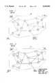
- FIG. 1depicts a schematic diagram of a packet-based telecommunications network in the prior art, which enables host computers that have access to the network (e.g., Alice, Bob, Charlie and Denise) to communicate.
- network 101comprises a plurality of geographically distributed packet switches that are interconnected by duplex communication links in the topology of a graph.
- Each packet switch in network 101is schematically depicted by a circle that encompasses a unique whole number, from 1 to 15, and each duplex communication link is depicted by a dotted line that interconnects two circles.
- Alice, Bob, Charlie and Deniseeach have access to network 101 via packet switches #8, #13, #10 and #3, respectively.
- the transmitting hostparses the information into a set of packets, which are serially presented to the network.
- the sequential order in which the set of packets are presented to the networkmight also be the order in which the packets are preferably delivered by the network. In other words, in some cases it may be advantageous for network 101 to preserve the sequential order of the packets, and in other cases it may be inconsequential.
- connectionless (i.e., datagram) servicewhich does not preserve the sequential order of the packets
- connection-oriented (i.e., virtual-circuit) servicewhich does preserve the sequential order of the packets.
- datagram service and virtual servicehave their respective advantages and disadvantages, which will be described in detail below.
- the book Computer Networks, 2nd Ed., by Andrew S. Tanenbaum, Prentice-Hall, Inc.provides an excellent introduction to packet-based telecommunications and is hereby incorporated by reference as if set forth in its entirety.
- each piece of mailcan take alternative routes to the same ultimate destination. And because the length of each route can vary, and so too the speed through each route, two pieces of mail that were mailed concurrently can arrive at different times. It is also further the case that two pieces of mail, mailed sequentially from the same place and to the same ultimate destination can arrive out of order.
- a datagram networkcan transport packets via different routes such that a set of packets that were presented to the network in one sequential order can be delivered by the network in a different order.
- multiple elemental networksare usually fabricated as a composite physical network, as shown in FIG. 1.
- a duplex communication channel or networkis, in reality, a composite of two simplex communication channels or elemental networks.
- an elemental networkis defined as one or more integrated simplex communication channels that are capable of delivering packets to a destination, which destination may be a packet switch or host computer.
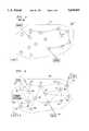
- FIGS. 2 and 3depict examples of elemental networks, in accordance with connectionless techniques well known in the prior art.
- FIG. 2depicts an elemental network that transports packets from packet switch #3 to packet switch #10
- FIG. 3depicts a elemental network that transports packets from packet switch #13 to packet switch #3.
- Each packet switch in a network that provides datagram servicecontains a router table that indicates where it should route packets that arrive at it.
- Table 1depicts a typical router table that might be associated with packet switch #3 in FIG. 1 (when network 101 provides only datagram service).
- the packet switchlooks at the address in the packet's addressee field and uses that address as an index into the router table to determine to which neighboring packet switch the packet should be routed.
- the neighboring packet switches of packet switch #3are packet switches #1, #2, #5 and #7. In this manner, packets are handed from one packet switch to another, in bucket brigade fashion, until they reach their final destination.
- the packet switchlearns from Table 1 that the preference is to send the packet to packet switch #7.
- the router tableindicates that the second choice is to send the packet to packet switch #5. For similar reasons, more alternative choices may also be given. Note that when a packet arrives with address 3 in the packet's addressee field, meaning that the packet has arrived at its destination in the network, the router table indicates that the packet is to be passed to the appropriate host that is associated with the packet switch.
- Network control in datagram networksi.e., the process of dealing with network congestion, packet switch and communication link failure, network administration, network maintenance, etc.
- each packet switchin a distributed fashion and is accomplished by providing each packet switch with alternative destinations to which packets can be routed.
- FIGS. 4 and 5depict examples of elemental networks from Denise to Charlie.
- each packetis required to carry an identifier of the virtual-circuit that it is associated with.
- Each packet switch in a network that provides virtual-circuit servicecontains a router table that guides the packet switch where to route each packet that arrives at it.
- Table 2depicts a typical router table that might be associated with packet switch #3 when it provides virtual-circuit service.
- a packet switch that provides virtual-circuit servicemust perform a different task than a packet switch that provides datagram service.
- the packet switchuses the router table in Table 2 not only to learn which packet switch the packet is to be routed through, but also with which virtual-channel identifier ("VCI"). Therefore, each packet switch must overwrite, in each packet's VCI field, the name of the outgoing virtual-channel into which the packet is put.
- the packet switchoutputs the packet to packet switch #7 and overwrites the VCI of 3 with a 2.
- Virtual-circuit networksdeal with network congestion and network failures by setting-up new virtual-circuits in less congested, working parts of the network. In other words, entries are usually made into the router tables in virtual-circuit networks at call set-up, in contrast with datagram networks where in the entries are made into the router tables before call establishment.
- Embodiments of the present inventionare packet-based networks that preserve the sequential order of packets, without many of the costs and restrictions found in the prior art.
- packets in embodiments of the present inventionmaintain sequence, unlike in datagram networks, or node-by-node call set-up procedures, as in virtual-circuit networks, in order to preserve the order of the packets.
- networks that are fabricated in accordance with the present inventioncan be substantially less expensive to build and operate than similar-capacity networks in the prior art.
- An illustrative embodiment of the present inventioncomprises a plurality of different elemental networks, each of which has the topology of a sink tree with a root, and such that at least one packet switch is the root for at least two of the elemental networks.
- FIG. 1depicts a packet-based telecommunications network in the prior art.
- FIG. 2depicts a first elemental network, configured to provide datagram service, that is a component of the network in FIG. 1.
- FIG. 3depicts a second elemental network, configured to provide datagram service, that is a component of the network in FIG. 1.
- FIG. 4depicts a third elemental network, configured to provide virtual-circuit service, that is a component of the network in FIG. 1.
- FIG. 5depicts a fourth elemental network, configured to provide virtual-circuit service, that is a component of the network in FIG. 1.
- FIG. 6depicts a packet-based telecommunications network in accordance with the exemplary embodiment.
- FIG. 7depicts the format of a packet in accordance with the exemplary embodiment.
- FIG. 8depicts the format of the header of a packet, in accordance with the exemplary embodiment.
- FIG. 9depicts a block diagram of the architecture of a packet switch in accordance with the exemplary embodiment.
- FIG. 10depicts a first elemental network, with the topology of a sink tree in accordance with the exemplary embodiment.
- FIG. 11depicts a second elemental network, with the topology of a sink tree in accordance with the exemplary embodiment.
- FIG. 12depicts a third elemental network, with the topology of a sink tree in accordance with the exemplary embodiment.
- FIG. 13depicts a fourth elemental network, with the topology of a sink tree in accordance with the exemplary embodiment.
- FIG. 14depicts a fifth elemental network, with the topology of a sink tree in accordance with the exemplary embodiment.
- FIG. 15depicts the fifth elemental network of FIG. 14 as it has been re-configured in accordance with the exemplary embodiment.
- FIG. 16depicts a flow chart of the exemplary operation of a network controller in accordance with the exemplary embodiment.
- FIG. 6depicts a schematic diagram of a packet-based telecommunications network, in accordance with the exemplary embodiment, which enables a plurality of host computers that have access to the network (e.g., Alice 611, Bob 613, Charlie 615, and Denise 617) to communicate.
- the networke.g., Alice 611, Bob 613, Charlie 615, and Denise 617
- Network 601preferably comprises a plurality of geographically distributed packet switches that are interconnected by duplex communication links in the topology of a graph.
- Each physical packet switch in network 601is schematically depicted by a circle that encompasses a unique whole number, from 1 to 15, and each duplex communication link is depicted by a dotted line that interconnects two circles.
- the exemplary embodimentis characterized by the topology shown in FIG. 6, it will be clear to those skilled in the art how to make and use networks in accordance with the present invention that have an arbitrary number of packet switches in a different topology.
- the packet switches in the exemplary embodimentare advantageously different than packet switches in the prior art, as will be discussed below, it will be clear to those skilled in the art that with inexpensive modifications, packet switches in the prior art, which provide either datagram service or virtual-circuit service, can be jury-rigged to provide service in accordance with the present invention.
- the communication links in each elemental networkare preferably simplex and can be fabricated from components and techniques well known in the prior art.
- a plurality of elemental networks in accordance with the present inventionare fabricated, it will be clear that, in some cases, it will be preferable to fabricate some pairs of simplex communication links from a hardware duplex communication link.
- multiple elemental networks in accordance with the illustrative embodiment, in some cases,are preferably fabricated from composite packet switches and duplex communication links.
- the communication links that interconnect the various packet switches in embodiments of the present inventioncan either be wireless (e.g., radio or free-space optics), wireline or a combination of the two. It is preferred, however, that they be wireless.
- network 601preferably further comprises network controller 603, which preferably has the responsibility for the network administration functions that will be discussed below. While network controller 603 can either be (1) centralized, (2) distributed, or (3) at least partially distributed, it is preferred that network controller be distributed among the various packet switches in the network. It will be clear to those skilled in the art how to make and use network controller 603 in accordance with the present invention.
- network controller 603be capable of accessing, either directly or indirectly, and configuring each packet switch, including its router table, in network 601. From the discussion below, it will be clear to those skilled in the art how to make and use network controller 603 in a manner that is most appropriate to a given network.
- each packet routed through network 601preferably comprises a header portion and a payload portion.
- the format of the payload portionis not a part of the present invention and is agreed to, by convention, by the respective host computers that are communicating using the packet.
- the standard cell format for Asynchronous Transfer Mode (“ATM")can used, although the meaning given to one or more of the fields in the ATM cell header must be changed in accordance with the present invention.
- FIG. 8depicts the preferred format of the header portion of the packet, which preferably comprises an addressee field and a miscellaneous field.
- the miscellaneous fieldadvantageously comprises error correction and detection information, sequencing information, and the address of the addressor, as is well known to those skilled in the art.
- the addressee fieldcontains an address or name of the destination to which the packet is ultimately addressed.
- the Virtual Path Indicator (“VPI") fieldbe interpreted instead as the addressee field and, therefore, that the VPI field contain not an indicator of the virtual path in which the packet is being transmitted, but only the address or name of the destination to which the packet is ultimately addressed.
- each packet switch in network 601has the design of packet switch 901, shown in FIG. 9.
- Packet switch 901preferably comprises one or more input ports, two or more output ports (each one uniquely connected to a neighboring packet switch by a simplex communication link), switching fabric 911 that can route a packet received at any of the input ports to any of the neighbor packet switches (via the appropriate output port), switch controller 915, router table 913, which depending on how it is populated directs switching fabric 911 which output port to direct incoming packets to, and network controller 603.
- switching fabric 911is well-known in the art and can be fabricated in a myriad number of ways, including: from a time-division switch, a space-division switch, a time-and-space division switch, etc. From the following description, it will be clear to those skilled in the art how to make and use packet switch 901.
- Table 3depicts the preferred format of router table 9 13, which preferably has a plurality of addressee entries and an indicia of a single, neighboring packet switch associated with each of the addressee entries.
- router table 913can alternatively have a format that bases the destination packet switch on both the contents of a packet's addressee field and on the packet switch from which the packet arrived.
- Table 4depicts such an alternative table.
- each packet switch in network 601is preferably assigned, or has associated with it, a plurality of addresses (alternatively called "names" throughout this specification), although it is only necessary that those packet switches that are the ultimate destination for a packet be even associated with any name.
- namesalternatively called "names" throughout this specification
- network controller 603will vary the number of names associated with each packet switch over time.
- each of the names associated with a packet switchshall be labeled by the number of a physical packet switch suffixed with an alphabetic string.
- the namescould be #10a, #10b and #10c.
- all names and addressesare advantageously represented by binary strings, which may be interpreted as integers rather than as alphanumeric strings.
- a plurality of different elemental networkseach having the topology of a "sink tree" with a "root” are formed from a plurality of packet switches and a plurality of simplex communication links.
- each elemental networkpreferably comprises a subset, or proper subset (being a mathematical subset that does not contain all the elements of the inclusive set from which it is derived) of all the packet switches in network 601, at least one, and preferably all, of the packet switches are the root for at least two different elemental networks.
- each elemental networkcan comprise the same set of packet switches as another elemental network, it is preferred that the two elemental networks have a different topology.
- each elemental network in accordance with the present inventionis to provide simplex access to a destination (either a packet switch or host computer) from all of the other packet switches in that elemental network. It is preferred that for each destination in network 601, there exist multiple, different elemental networks, each with the topology of a sink tree with a packet switch at the root. It is further preferred that each packet switch have access to every destination.
- a "directed graph” with no cyclesis called a “directed acyclic graph” and a “sink tree” is a directed acyclic graph that satisfies the following properties:
- At least one vertexhas at least two entering edges.
- packet switch #10when packet switch #10 has three names associated with it (e.g., 10a, 10b and 10c), some or all of the router tables in network 601 are populated so that for those three names there are three different elemental networks that have packet switch #10 at the root.
- FIGS. 10, 11 and 12depict the three different elemental networks associated with names 10a, 10b and 10c, respectively. Note that the elemental network associated with name 10a does not contain packet switches #8, #9 or #11 and the elemental network associated with name 10c does not contain packet switches #5 or #6.
- Table 5depicts that portion of the router table in packet switch #13 associated with names 10a, 10b and 10c, and Table 6 depicts that portion of the router table in packet switch with those addresses.
- FIG. 10depicts the illustrative elemental network associated with name "10a.”
- a packet deposited in network 601at packet switch whose router table has been populated to recognize address "10a"
- packet switch #13would route that packet to packet switch #12.
- the router table in packet switch #13indicates a "12" as corresponding to the address "10a” entry.
- packet switch #12would route the packet to packet switch #10, as directed by the router table shown in packet switch #12.
- FIGS. 11 and 12each illustrate elemental networks associated with the names "10b" and "10c,” respectively.
- the packet switches in the exemplary embodimentpreferably do not alter the address in a packet's addressee field.
- the individual sink treescould be fabricated from a virtual-circuit network, it is preferred that they do not because of the unnecessary address translation that it would entail.
- FIGS. 13 and 14each depict illustrative elemental networks associated with the names "13a" and "13b,” respectively.
- FIG. 15depicts how the illustrative elemental network depicted in FIG. 14 can be re-configured when the communication link between packet switches #10 and #12 fails, becomes congested, or otherwise becomes unfavorable. Note that to re-configure the elemental network associated with the name #13b, the router tables in packet switches #10 and #15 must be altered. It should be noted that packet switch//5 has been dropped and packet switch #9 has been added to the elemental network depicted in FIG. 15 as part of the reconfiguration process.
- network controller 603The purpose of network controller 603 is to manage the flow of packets through network 601 either: (1) by changing the number of different elemental networks that compose network 601, (2) by changing which packet switches are on each of the different elemental networks, and/or (3) by changing the addresses which various sources use when addressing packets to a destination and, therefore, which elemental networks are actually used.
- network controller 603begins the process of administering the network at step 1603 by determining the topology of the network.
- the techniques for doing soare well known in the art and can comprise either centralized or distributed techniques, although distributed techniques are preferred.
- network controller 603either assigns or associates one or more addresses to each packet switch in the network.
- the techniques for performing this stepare also well known in the art and can comprise either centralized or distributed techniques.
- network controller 603periodically or sporadically populates or repopulates the router tables in each of the packet switches so that, for each address that is associated with a packet switch, a elemental network is formed with the topology of a sink tree with the associated packet switch at the root of the tree.
- each host computer and packet switch that can send packetsmaintain an "address book," which indicates how each should address packets to a destination.
- Table 7depicts an illustrative address book for Alice. Alice's address book indicates that she should use address 13a to send packets to Bob, address 10c to send packets to Charlie, and address 3e to send packets to Denise.
- network controller 603may effectively send a message to Alice that states "When you want to send packets to Bob, use address "13a;” when you want to send packets to Charlie, use address "10c;” when you want to send packets to Denise, use address "3e.” Note that it is possible, and may be advantageous in certain circumstances, for two different hosts (e.g., Alice and Bob) to send packets to a single destination host (e.g., Charlie) with different addresses (e.g., 10c and 10a, respectively) simultaneously.
- Network controller 603advantageously keeps, and periodically or sporadically changes, a "network address book," which is a composite of the address books kept by each host.
- a typical network address bookis depicted in Table 8.
- step 1311network controller 603 gathers network traffic information, which preferably comprises congestion, administration and reliability information from around the network so that it can have the information that it needs to gracefully deal with network congestion, communication link and packet switch failures and the addition and subtraction of host computers, packet switches and communication links. It will be clear to those skilled in the art how to implement step 1311.
- network controller 603uses the information gathered in step 1311 to determine how to re-configure network 601. In other words, whether to add or subtract elemental networks, whether to add or subtract packet switches to elemental networks, whether to re-populate router tables, and/or whether to change the address books of some of the host computers and/or packet switches.
- step 1313network controller 603 also deals with the addition and/or subtraction of packet switches, communication links and host computers. It will be clear to those skilled in the art how to perform step 1313. From step 1313, control passes back to step 1607 where network controller re-populates the various packet switches to implement the new set of elemental networks.
- each name associated with each packet switch in network 601there is a different elemental network in the topology of the tree.
- the advantages to be gained from the use of elemental networks in the topology of sink trees, in contrast to datagram and virtual-circuit networksare primarily these.
- network 601preserves the sequential order in which the packets are presented to the network because from any given source to any destination, there is only one path.
- the architecture of the packet switchescan be less expensive to make and use than the packet switches used in datagram and virtual-circuit switches in the prior art.
Landscapes
- Engineering & Computer Science (AREA)
- Computer Networks & Wireless Communication (AREA)
- Signal Processing (AREA)
- Data Exchanges In Wide-Area Networks (AREA)
Abstract
Description
TABLE 1 ______________________________________ A Typical Router Table in a Packet Switch in a Datagram Network (Packet Switch #3) ______________________________________ ##STR1## ______________________________________
TABLE 2 ______________________________________ A Typical Router Table in a Virtual Circuit Network ______________________________________ ##STR2## ______________________________________
TABLE 3 ______________________________________ Preferred Router Table Format ______________________________________ ##STR3## ______________________________________
TABLE 4 ______________________________________ Alternative Router Table Format ______________________________________ ##STR4## ______________________________________
TABLE 5 ______________________________________ A Portion of the Router Table inPacket Switch # 13 ______________________________________ ##STR5## ______________________________________
TABLE 6 ______________________________________ A portion of the Router Table inPacket Switch # 12 ______________________________________ ##STR6## ______________________________________
TABLE 7 ______________________________________ Alice's Address Book ______________________________________ ##STR7## ______________________________________
TABLE 8 ______________________________________Network Controller 601 Address Book (addressor appears on left, addressee on top) ______________________________________ ##STR8## ______________________________________
Claims (29)
Priority Applications (4)
| Application Number | Priority Date | Filing Date | Title |
|---|---|---|---|
| US08/412,400US5610904A (en) | 1995-03-28 | 1995-03-28 | Packet-based telecommunications network |
| EP96301888AEP0735726A2 (en) | 1995-03-28 | 1996-03-20 | A packet-based telecommunications network |
| KR1019960008577AKR100361424B1 (en) | 1995-03-28 | 1996-03-27 | A packet-based telecommunications network |
| JP07340896AJP3177438B2 (en) | 1995-03-28 | 1996-03-28 | Packet-based telecommunications network |
Applications Claiming Priority (1)
| Application Number | Priority Date | Filing Date | Title |
|---|---|---|---|
| US08/412,400US5610904A (en) | 1995-03-28 | 1995-03-28 | Packet-based telecommunications network |
Publications (1)
| Publication Number | Publication Date |
|---|---|
| US5610904Atrue US5610904A (en) | 1997-03-11 |
Family
ID=23632814
Family Applications (1)
| Application Number | Title | Priority Date | Filing Date |
|---|---|---|---|
| US08/412,400Expired - LifetimeUS5610904A (en) | 1995-03-28 | 1995-03-28 | Packet-based telecommunications network |
Country Status (4)
| Country | Link |
|---|---|
| US (1) | US5610904A (en) |
| EP (1) | EP0735726A2 (en) |
| JP (1) | JP3177438B2 (en) |
| KR (1) | KR100361424B1 (en) |
Cited By (27)
| Publication number | Priority date | Publication date | Assignee | Title |
|---|---|---|---|---|
| US5740172A (en)* | 1995-06-09 | 1998-04-14 | Samsung Electronics Co., Ltd. | Method for searching a packet transmission path in a broadband information and communication system |
| US5991824A (en)* | 1997-02-06 | 1999-11-23 | Silicon Graphics, Inc. | Method and system for simultaneous high bandwidth input output |
| US6081506A (en)* | 1997-11-19 | 2000-06-27 | At&T Corp | Integrating switching and facility networks using ATM |
| US20010051865A1 (en)* | 1996-05-28 | 2001-12-13 | Cisco Systems, Inc. | Network flow switching and flow data export |
| US6347340B1 (en)* | 2000-02-18 | 2002-02-12 | Mobilesys, Inc. | Apparatus and method for converting a network message to a wireless transport message using a modular architecture |
| US20020120874A1 (en)* | 2000-12-22 | 2002-08-29 | Li Shu | Method and system for secure exchange of messages |
| US20030031213A1 (en)* | 2001-08-09 | 2003-02-13 | Joachim Charzinski | Device and method for setting up standby paths in a transport network for dual homing |
| US20030053475A1 (en)* | 2001-05-23 | 2003-03-20 | Malathi Veeraraghavan | Transferring data such as files |
| US20030115364A1 (en)* | 2001-12-19 | 2003-06-19 | Li Shu | Camouflage of network traffic to resist attack |
| US20030128706A1 (en)* | 2001-06-14 | 2003-07-10 | Mark Barry Ding Ken | Extension of link aggregation protocols over the network |
| US6636508B1 (en)* | 1999-02-12 | 2003-10-21 | Nortel Networks Limted | Network resource conservation system |
| US6654359B1 (en)* | 1998-12-11 | 2003-11-25 | Lucent Technologies Inc. | Wireless access to packet-based networks |
| US20040022237A1 (en)* | 1998-11-20 | 2004-02-05 | Level 3 Communications, Inc. | Voice over data telecommunications network architecture |
| US6711171B1 (en)* | 1995-11-15 | 2004-03-23 | Enterasys Networks, Inc. | Distributed connection-oriented services for switched communications networks |
| US6714547B1 (en)* | 1999-02-04 | 2004-03-30 | Nec Corporation | Quality-ensuring routing technique |
| US20040063442A1 (en)* | 2002-09-26 | 2004-04-01 | Interdigital Technology Corporation | Method for enabling multicast services and user equipment battery savings |
| US6728205B1 (en)* | 1997-02-19 | 2004-04-27 | Massachusetts Institute Of Technology | Method and apparatus for automatic protection switching |
| US6798776B1 (en)* | 1995-12-29 | 2004-09-28 | Cisco Technology, Inc. | Method for traffic management, traffic prioritization, access control, and packet forwarding in a datagram computer network |
| US6816460B1 (en)* | 2000-03-14 | 2004-11-09 | Lucent Technologies Inc. | Location based routing for mobile ad-hoc networks |
| US20050083949A1 (en)* | 1995-11-15 | 2005-04-21 | Kurt Dobbins | Distributed connection-oriented services for switched communication networks |
| US7002958B1 (en)* | 1999-09-10 | 2006-02-21 | Pluris, Inc. | Method for load-balancing with FIFO guarantees in multipath networks |
| US20060148516A1 (en)* | 2002-10-01 | 2006-07-06 | Interdigital Technology Corporation | Wireless communication method and system with controlled WTRU peer-to-peer communications |
| US20070036129A1 (en)* | 2005-07-15 | 2007-02-15 | Alcatel | Method and system for encoding packet interdependency in a packet data transmission system |
| US7260518B2 (en) | 1996-05-28 | 2007-08-21 | Cisco Technology, Inc. | Network flow switching and flow data report |
| US7653059B1 (en)* | 2002-12-20 | 2010-01-26 | Symantec Operating Corporation | Communication sessions for a computer network |
| US20100254378A1 (en)* | 2009-04-03 | 2010-10-07 | Srinivasa Aditya Akella | Network routing system providing increased network bandwidth |
| US20150334024A1 (en)* | 2012-04-20 | 2015-11-19 | Jeffrey Clifford Mogul | Controlling Data Rates of Data Flows Based on Information Indicating Congestion |
Families Citing this family (4)
| Publication number | Priority date | Publication date | Assignee | Title |
|---|---|---|---|---|
| EP1269695B1 (en)* | 2000-03-31 | 2008-07-02 | BRITISH TELECOMMUNICATIONS public limited company | Communications network |
| JP4425863B2 (en)* | 2004-02-18 | 2010-03-03 | 株式会社エヌ・ティ・ティ・ドコモ | Packet transfer system and radio base station |
| JPWO2006001308A1 (en)* | 2004-06-24 | 2008-04-17 | 松下電器産業株式会社 | Wireless system, wireless node device, and path control device |
| KR102058082B1 (en) | 2018-11-22 | 2019-12-20 | (주)하몬소프트 | Software-defined networking apparatus based on service profile learning |
Citations (3)
| Publication number | Priority date | Publication date | Assignee | Title |
|---|---|---|---|---|
| US4987536A (en)* | 1988-05-12 | 1991-01-22 | Codex Corporation | Communication system for sending an identical routing tree to all connected nodes to establish a shortest route and transmitting messages thereafter |
| US5253248A (en)* | 1990-07-03 | 1993-10-12 | At&T Bell Laboratories | Congestion control for connectionless traffic in data networks via alternate routing |
| US5428636A (en)* | 1993-05-03 | 1995-06-27 | Norand Corporation | Radio frequency local area network |
Family Cites Families (1)
| Publication number | Priority date | Publication date | Assignee | Title |
|---|---|---|---|---|
| CA1245327A (en) | 1985-09-06 | 1988-11-22 | Northern Telecom Limited | Path oriented routing system and method for packet switching networks |
- 1995
- 1995-03-28USUS08/412,400patent/US5610904A/ennot_activeExpired - Lifetime
- 1996
- 1996-03-20EPEP96301888Apatent/EP0735726A2/ennot_activeWithdrawn
- 1996-03-27KRKR1019960008577Apatent/KR100361424B1/ennot_activeExpired - Lifetime
- 1996-03-28JPJP07340896Apatent/JP3177438B2/ennot_activeExpired - Lifetime
Patent Citations (3)
| Publication number | Priority date | Publication date | Assignee | Title |
|---|---|---|---|---|
| US4987536A (en)* | 1988-05-12 | 1991-01-22 | Codex Corporation | Communication system for sending an identical routing tree to all connected nodes to establish a shortest route and transmitting messages thereafter |
| US5253248A (en)* | 1990-07-03 | 1993-10-12 | At&T Bell Laboratories | Congestion control for connectionless traffic in data networks via alternate routing |
| US5428636A (en)* | 1993-05-03 | 1995-06-27 | Norand Corporation | Radio frequency local area network |
Non-Patent Citations (2)
| Title |
|---|
| IEEE Infocom '94 "The Sink Tree Paradigm: Connectionless Traffic Support on ATM LANs" by R. Cohen, B. V. Patel, F. Schaffa, and M. Willebeek-LeMair. Proceedings vol. 2 pp. 821-828. Jun. 12-16, 1994. |
| IEEE Infocom 94 The Sink Tree Paradigm: Connectionless Traffic Support on ATM LANs by R. Cohen, B. V. Patel, F. Schaffa, and M. Willebeek LeMair. Proceedings vol. 2 pp. 821 828. Jun. 12 16, 1994.* |
Cited By (56)
| Publication number | Priority date | Publication date | Assignee | Title |
|---|---|---|---|---|
| US5740172A (en)* | 1995-06-09 | 1998-04-14 | Samsung Electronics Co., Ltd. | Method for searching a packet transmission path in a broadband information and communication system |
| US20100177778A1 (en)* | 1995-11-15 | 2010-07-15 | Enterasys Networks, Inc. | Distributed connection-oriented services for switched communication networks |
| US7720076B2 (en) | 1995-11-15 | 2010-05-18 | Enterasys, Inc. | Distributed connection-oriented services for switched communication networks |
| US20050083949A1 (en)* | 1995-11-15 | 2005-04-21 | Kurt Dobbins | Distributed connection-oriented services for switched communication networks |
| US8462794B2 (en) | 1995-11-15 | 2013-06-11 | Enterasys Networks, Inc. | Distributed connection-oriented services for switched communication networks |
| US6711171B1 (en)* | 1995-11-15 | 2004-03-23 | Enterasys Networks, Inc. | Distributed connection-oriented services for switched communications networks |
| US8023515B2 (en) | 1995-11-15 | 2011-09-20 | Enterasys Networks, Inc. | Distributed connection-oriented services for switched communication networks |
| US20100182934A1 (en)* | 1995-11-15 | 2010-07-22 | Enterasys Networks, Inc. | Distributed connection-oriented services for switched communication networks |
| US20090046734A1 (en)* | 1995-12-29 | 2009-02-19 | Cisco Technology, Inc. | Method for Traffic Management, Traffic Prioritization, Access Control, and Packet Forwarding in a Datagram Computer Network |
| US6798776B1 (en)* | 1995-12-29 | 2004-09-28 | Cisco Technology, Inc. | Method for traffic management, traffic prioritization, access control, and packet forwarding in a datagram computer network |
| US7443858B1 (en) | 1995-12-29 | 2008-10-28 | Cisco Technology, Inc. | Method for traffic management, traffic prioritization, access control, and packet forwarding in a datagram computer network |
| US8401027B2 (en) | 1995-12-29 | 2013-03-19 | Cisco Technology, Inc. | Method for traffic management, traffic prioritization, access control, and packet forwarding in a datagram computer network |
| US6590894B1 (en)* | 1996-05-28 | 2003-07-08 | Cisco Technology, Inc. | Network flow switching and flow data export |
| US7475156B2 (en)* | 1996-05-28 | 2009-01-06 | Cisco Technology, Inc. | Network flow switching and flow data export |
| US7260518B2 (en) | 1996-05-28 | 2007-08-21 | Cisco Technology, Inc. | Network flow switching and flow data report |
| US20010051865A1 (en)* | 1996-05-28 | 2001-12-13 | Cisco Systems, Inc. | Network flow switching and flow data export |
| US5991824A (en)* | 1997-02-06 | 1999-11-23 | Silicon Graphics, Inc. | Method and system for simultaneous high bandwidth input output |
| US6728205B1 (en)* | 1997-02-19 | 2004-04-27 | Massachusetts Institute Of Technology | Method and apparatus for automatic protection switching |
| US6081506A (en)* | 1997-11-19 | 2000-06-27 | At&T Corp | Integrating switching and facility networks using ATM |
| US20040022237A1 (en)* | 1998-11-20 | 2004-02-05 | Level 3 Communications, Inc. | Voice over data telecommunications network architecture |
| US8036214B2 (en) | 1998-11-20 | 2011-10-11 | Level 3 Communications, Llc | Voice over data telecommunications network architecture |
| US8693347B2 (en) | 1998-11-20 | 2014-04-08 | Level 3 Communications, Llc | Voice over data telecommunications network architecture |
| US8270421B2 (en) | 1998-11-20 | 2012-09-18 | Level 3 Communications, Llc | Voice over data telecommunications network architecture |
| US8089958B2 (en) | 1998-11-20 | 2012-01-03 | Level 3 Communications, Llc | Voice over data telecommunications network architecture |
| US8085761B2 (en) | 1998-11-20 | 2011-12-27 | Level 3 Communications, Llc | Voice over data telecommunications network architecture |
| US7564840B2 (en) | 1998-11-20 | 2009-07-21 | Level 3 Communications, Llc | Voice over data telecommunications network architecture |
| US20080025295A1 (en)* | 1998-11-20 | 2008-01-31 | Elliott Isaac K | Voice over data telecommunications network architecture |
| US20080025294A1 (en)* | 1998-11-20 | 2008-01-31 | Elliott Isaac K | Voice over data telecommunications network architecture |
| US20080013531A1 (en)* | 1998-11-20 | 2008-01-17 | Elliott Isaac K | Voice over data telecommunications network architecture |
| US6654359B1 (en)* | 1998-12-11 | 2003-11-25 | Lucent Technologies Inc. | Wireless access to packet-based networks |
| US6714547B1 (en)* | 1999-02-04 | 2004-03-30 | Nec Corporation | Quality-ensuring routing technique |
| US6636508B1 (en)* | 1999-02-12 | 2003-10-21 | Nortel Networks Limted | Network resource conservation system |
| US7002958B1 (en)* | 1999-09-10 | 2006-02-21 | Pluris, Inc. | Method for load-balancing with FIFO guarantees in multipath networks |
| US6347340B1 (en)* | 2000-02-18 | 2002-02-12 | Mobilesys, Inc. | Apparatus and method for converting a network message to a wireless transport message using a modular architecture |
| US6816460B1 (en)* | 2000-03-14 | 2004-11-09 | Lucent Technologies Inc. | Location based routing for mobile ad-hoc networks |
| US20020120874A1 (en)* | 2000-12-22 | 2002-08-29 | Li Shu | Method and system for secure exchange of messages |
| US20030053475A1 (en)* | 2001-05-23 | 2003-03-20 | Malathi Veeraraghavan | Transferring data such as files |
| US7965729B2 (en)* | 2001-05-23 | 2011-06-21 | Polytechnic University | Transferring data such as files |
| US20030128706A1 (en)* | 2001-06-14 | 2003-07-10 | Mark Barry Ding Ken | Extension of link aggregation protocols over the network |
| US6956824B2 (en)* | 2001-06-14 | 2005-10-18 | Tropic Networks Inc. | Extension of link aggregation protocols over the network |
| DE10139156A1 (en)* | 2001-08-09 | 2003-03-13 | Siemens Ag | Device and method for setting up replacement paths in a transport network for dual homing |
| US20030031213A1 (en)* | 2001-08-09 | 2003-02-13 | Joachim Charzinski | Device and method for setting up standby paths in a transport network for dual homing |
| DE10139156B4 (en)* | 2001-08-09 | 2007-02-01 | Siemens Ag | An optical transmission system and method for establishing a spare data connection in a dual-homing transport network |
| US20030115364A1 (en)* | 2001-12-19 | 2003-06-19 | Li Shu | Camouflage of network traffic to resist attack |
| US7171493B2 (en) | 2001-12-19 | 2007-01-30 | The Charles Stark Draper Laboratory | Camouflage of network traffic to resist attack |
| US20090122742A1 (en)* | 2002-09-26 | 2009-05-14 | Interdigital Technology Corporation | Method for utilizing multicast services to enhance user equipment battery life |
| US20040063442A1 (en)* | 2002-09-26 | 2004-04-01 | Interdigital Technology Corporation | Method for enabling multicast services and user equipment battery savings |
| US7486637B2 (en) | 2002-09-26 | 2009-02-03 | Interdigital Technology Corporation | Wireless communication method and system for efficiently managing paging windows and data messages |
| US7239874B2 (en)* | 2002-10-01 | 2007-07-03 | Interdigital Technology Corporation | Wireless communication method and system with controlled WTRU peer-to-peer communications |
| US20060148516A1 (en)* | 2002-10-01 | 2006-07-06 | Interdigital Technology Corporation | Wireless communication method and system with controlled WTRU peer-to-peer communications |
| US7653059B1 (en)* | 2002-12-20 | 2010-01-26 | Symantec Operating Corporation | Communication sessions for a computer network |
| US7801126B2 (en)* | 2005-07-15 | 2010-09-21 | Alcatel-Lucent Usa Inc. | Method and system for encoding packet interdependency in a packet data transmission system |
| US20070036129A1 (en)* | 2005-07-15 | 2007-02-15 | Alcatel | Method and system for encoding packet interdependency in a packet data transmission system |
| US20100254378A1 (en)* | 2009-04-03 | 2010-10-07 | Srinivasa Aditya Akella | Network routing system providing increased network bandwidth |
| US9438504B2 (en)* | 2009-04-03 | 2016-09-06 | Wisconsin Alumni Research Foundation | Network routing system providing increased network bandwidth |
| US20150334024A1 (en)* | 2012-04-20 | 2015-11-19 | Jeffrey Clifford Mogul | Controlling Data Rates of Data Flows Based on Information Indicating Congestion |
Also Published As
| Publication number | Publication date |
|---|---|
| JP3177438B2 (en) | 2001-06-18 |
| KR960036460A (en) | 1996-10-28 |
| JPH08279823A (en) | 1996-10-22 |
| EP0735726A2 (en) | 1996-10-02 |
| KR100361424B1 (en) | 2003-02-19 |
Similar Documents
| Publication | Publication Date | Title |
|---|---|---|
| US5610904A (en) | Packet-based telecommunications network | |
| US5940396A (en) | Method of routing in an asynchronous transfer mode network | |
| EP0997050B1 (en) | Method and apparatus for multipoint-to-point transmission in an atm network | |
| US6229787B1 (en) | Mechanism to achieve very fast failover in ATM backbone networks using multi-homed circuits | |
| US6078586A (en) | ATM virtual private networks | |
| US7130393B2 (en) | Intelligent network and method for providing voice telephony over ATM and closed user groups | |
| US6205146B1 (en) | Method of dynamically routing to a well known address in a network | |
| EP0524350B1 (en) | Telecommunication system for transmitting cells through switching nodes interconnected by groups of transmission links | |
| US7133403B1 (en) | Transport network and method | |
| JPH0685828A (en) | Method and apparatus for transfer in asynchronous transfer-mode metwork | |
| US6587467B1 (en) | Virtual channel multicast utilizing virtual path tunneling in asynchronous mode transfer networks | |
| US7058730B2 (en) | Unique address space and method for a transport network | |
| EP1021890B1 (en) | Virtual path merging in a multipoint-to-point network tunneling protocol | |
| US5627824A (en) | Telecommunications network | |
| JPH09504929A (en) | Method and apparatus for transmitting data packets in a multi-site network | |
| CN1551578B (en) | SVC/SPVC with L3 IP forwarding | |
| Bahattab | RETRACTED ARTICLE: A Survey on Packet Switching Networks | |
| Cisco | Introduction to MPLS | |
| Cisco | Introduction to MPLS | |
| US20050249229A1 (en) | Dynamically scalable edge router | |
| WO2003069854A1 (en) | Port label switching | |
| EP1317808B1 (en) | Method and arrangement for forming data streams | |
| Catania et al. | High-speed data service in distributed systems based on SMDS | |
| US20010005380A1 (en) | Network node for switching digital information of different protocol types | |
| JPH05191456A (en) | Packet relaying method for packet switching network |
Legal Events
| Date | Code | Title | Description |
|---|---|---|---|
| AS | Assignment | Owner name:AT&T IPM CORP., FLORIDA Free format text:ASSIGNMENT OF ASSIGNORS INTEREST;ASSIGNORS:ENG, KAI YIN;KAROL, MARK JOHN;VEERARAGHAVAN, MALATHI;REEL/FRAME:007508/0750 Effective date:19950517 | |
| AS | Assignment | Owner name:LUCENT TECHNOLOGIES INC., NEW JERSEY Free format text:ASSIGNMENT OF ASSIGNORS INTEREST;ASSIGNOR:AT&T CORP.;REEL/FRAME:008196/0181 Effective date:19960329 | |
| STCF | Information on status: patent grant | Free format text:PATENTED CASE | |
| FEPP | Fee payment procedure | Free format text:PAYOR NUMBER ASSIGNED (ORIGINAL EVENT CODE: ASPN); ENTITY STATUS OF PATENT OWNER: LARGE ENTITY | |
| FPAY | Fee payment | Year of fee payment:4 | |
| AS | Assignment | Owner name:THE CHASE MANHATTAN BANK, AS COLLATERAL AGENT, TEX Free format text:CONDITIONAL ASSIGNMENT OF AND SECURITY INTEREST IN PATENT RIGHTS;ASSIGNOR:LUCENT TECHNOLOGIES INC. (DE CORPORATION);REEL/FRAME:011722/0048 Effective date:20010222 | |
| FPAY | Fee payment | Year of fee payment:8 | |
| AS | Assignment | Owner name:LUCENT TECHNOLOGIES INC., NEW JERSEY Free format text:TERMINATION AND RELEASE OF SECURITY INTEREST IN PATENT RIGHTS;ASSIGNOR:JPMORGAN CHASE BANK, N.A. (FORMERLY KNOWN AS THE CHASE MANHATTAN BANK), AS ADMINISTRATIVE AGENT;REEL/FRAME:018584/0446 Effective date:20061130 | |
| FPAY | Fee payment | Year of fee payment:12 | |
| AS | Assignment | Owner name:CREDIT SUISSE AG, NEW YORK Free format text:SECURITY INTEREST;ASSIGNOR:ALCATEL-LUCENT USA INC.;REEL/FRAME:030510/0627 Effective date:20130130 | |
| AS | Assignment | Owner name:ALCATEL-LUCENT USA INC., NEW JERSEY Free format text:RELEASE BY SECURED PARTY;ASSIGNOR:CREDIT SUISSE AG;REEL/FRAME:033950/0001 Effective date:20140819 |