US5610733A - Beam-homogenizer - Google Patents
Beam-homogenizerDownload PDFInfo
- Publication number
- US5610733A US5610733AUS08/203,188US20318894AUS5610733AUS 5610733 AUS5610733 AUS 5610733AUS 20318894 AUS20318894 AUS 20318894AUS 5610733 AUS5610733 AUS 5610733A
- Authority
- US
- United States
- Prior art keywords
- homogenizer
- output
- plane
- incident
- holograms
- Prior art date
- Legal status (The legal status is an assumption and is not a legal conclusion. Google has not performed a legal analysis and makes no representation as to the accuracy of the status listed.)
- Expired - Lifetime
Links
- 238000009826distributionMethods0.000claimsabstractdescription57
- 230000003287optical effectEffects0.000claimsabstractdescription32
- 238000000034methodMethods0.000claimsdescription17
- 238000002834transmittanceMethods0.000abstractdescription5
- 230000008901benefitEffects0.000description6
- 230000000694effectsEffects0.000description6
- 238000013461designMethods0.000description4
- 238000000265homogenisationMethods0.000description4
- VYPSYNLAJGMNEJ-UHFFFAOYSA-NSilicium dioxideChemical compoundO=[Si]=OVYPSYNLAJGMNEJ-UHFFFAOYSA-N0.000description3
- 238000004519manufacturing processMethods0.000description3
- 239000000463materialSubstances0.000description3
- 229920000642polymerPolymers0.000description3
- 238000010521absorption reactionMethods0.000description2
- 238000013459approachMethods0.000description2
- 230000001427coherent effectEffects0.000description2
- 238000010276constructionMethods0.000description2
- 238000010894electron beam technologyMethods0.000description2
- 239000005350fused silica glassSubstances0.000description2
- 238000003698laser cuttingMethods0.000description2
- 230000008569processEffects0.000description2
- 206010034972Photosensitivity reactionDiseases0.000description1
- XUIMIQQOPSSXEZ-UHFFFAOYSA-NSiliconChemical compound[Si]XUIMIQQOPSSXEZ-UHFFFAOYSA-N0.000description1
- 230000003466anti-cipated effectEffects0.000description1
- 238000003491arrayMethods0.000description1
- 230000000903blocking effectEffects0.000description1
- 230000008859changeEffects0.000description1
- 238000005520cutting processMethods0.000description1
- 230000001627detrimental effectEffects0.000description1
- 238000005530etchingMethods0.000description1
- 238000007429general methodMethods0.000description1
- 239000000203mixtureSubstances0.000description1
- 238000012986modificationMethods0.000description1
- 230000004048modificationEffects0.000description1
- 239000013307optical fiberSubstances0.000description1
- 239000012788optical filmSubstances0.000description1
- 238000005457optimizationMethods0.000description1
- 230000036211photosensitivityEffects0.000description1
- 238000013139quantizationMethods0.000description1
- 230000035939shockEffects0.000description1
- 229910052710siliconInorganic materials0.000description1
- 239000010703siliconSubstances0.000description1
- 238000003892spreadingMethods0.000description1
- 230000007480spreadingEffects0.000description1
Images


Classifications
- G—PHYSICS
- G02—OPTICS
- G02B—OPTICAL ELEMENTS, SYSTEMS OR APPARATUS
- G02B27/00—Optical systems or apparatus not provided for by any of the groups G02B1/00 - G02B26/00, G02B30/00
- G02B27/09—Beam shaping, e.g. changing the cross-sectional area, not otherwise provided for
- G02B27/0927—Systems for changing the beam intensity distribution, e.g. Gaussian to top-hat
- B—PERFORMING OPERATIONS; TRANSPORTING
- B23—MACHINE TOOLS; METAL-WORKING NOT OTHERWISE PROVIDED FOR
- B23K—SOLDERING OR UNSOLDERING; WELDING; CLADDING OR PLATING BY SOLDERING OR WELDING; CUTTING BY APPLYING HEAT LOCALLY, e.g. FLAME CUTTING; WORKING BY LASER BEAM
- B23K26/00—Working by laser beam, e.g. welding, cutting or boring
- B23K26/02—Positioning or observing the workpiece, e.g. with respect to the point of impact; Aligning, aiming or focusing the laser beam
- B23K26/06—Shaping the laser beam, e.g. by masks or multi-focusing
- B23K26/064—Shaping the laser beam, e.g. by masks or multi-focusing by means of optical elements, e.g. lenses, mirrors or prisms
- B23K26/066—Shaping the laser beam, e.g. by masks or multi-focusing by means of optical elements, e.g. lenses, mirrors or prisms by using masks
- G—PHYSICS
- G02—OPTICS
- G02B—OPTICAL ELEMENTS, SYSTEMS OR APPARATUS
- G02B27/00—Optical systems or apparatus not provided for by any of the groups G02B1/00 - G02B26/00, G02B30/00
- G02B27/09—Beam shaping, e.g. changing the cross-sectional area, not otherwise provided for
- G—PHYSICS
- G02—OPTICS
- G02B—OPTICAL ELEMENTS, SYSTEMS OR APPARATUS
- G02B27/00—Optical systems or apparatus not provided for by any of the groups G02B1/00 - G02B26/00, G02B30/00
- G02B27/09—Beam shaping, e.g. changing the cross-sectional area, not otherwise provided for
- G02B27/0938—Using specific optical elements
- G02B27/0944—Diffractive optical elements, e.g. gratings, holograms
- G—PHYSICS
- G02—OPTICS
- G02B—OPTICAL ELEMENTS, SYSTEMS OR APPARATUS
- G02B5/00—Optical elements other than lenses
- G02B5/32—Holograms used as optical elements
- G—PHYSICS
- G03—PHOTOGRAPHY; CINEMATOGRAPHY; ANALOGOUS TECHNIQUES USING WAVES OTHER THAN OPTICAL WAVES; ELECTROGRAPHY; HOLOGRAPHY
- G03F—PHOTOMECHANICAL PRODUCTION OF TEXTURED OR PATTERNED SURFACES, e.g. FOR PRINTING, FOR PROCESSING OF SEMICONDUCTOR DEVICES; MATERIALS THEREFOR; ORIGINALS THEREFOR; APPARATUS SPECIALLY ADAPTED THEREFOR
- G03F7/00—Photomechanical, e.g. photolithographic, production of textured or patterned surfaces, e.g. printing surfaces; Materials therefor, e.g. comprising photoresists; Apparatus specially adapted therefor
- G03F7/70—Microphotolithographic exposure; Apparatus therefor
- G03F7/70058—Mask illumination systems
- G—PHYSICS
- G03—PHOTOGRAPHY; CINEMATOGRAPHY; ANALOGOUS TECHNIQUES USING WAVES OTHER THAN OPTICAL WAVES; ELECTROGRAPHY; HOLOGRAPHY
- G03H—HOLOGRAPHIC PROCESSES OR APPARATUS
- G03H1/00—Holographic processes or apparatus using light, infrared or ultraviolet waves for obtaining holograms or for obtaining an image from them; Details peculiar thereto
- G03H1/02—Details of features involved during the holographic process; Replication of holograms without interference recording
- G03H1/0236—Form or shape of the hologram when not registered to the substrate, e.g. trimming the hologram to alphanumerical shape
- G—PHYSICS
- G03—PHOTOGRAPHY; CINEMATOGRAPHY; ANALOGOUS TECHNIQUES USING WAVES OTHER THAN OPTICAL WAVES; ELECTROGRAPHY; HOLOGRAPHY
- G03H—HOLOGRAPHIC PROCESSES OR APPARATUS
- G03H1/00—Holographic processes or apparatus using light, infrared or ultraviolet waves for obtaining holograms or for obtaining an image from them; Details peculiar thereto
- G03H1/26—Processes or apparatus specially adapted to produce multiple sub- holograms or to obtain images from them, e.g. multicolour technique
- G03H1/30—Processes or apparatus specially adapted to produce multiple sub- holograms or to obtain images from them, e.g. multicolour technique discrete holograms only
- G03H2001/303—Interleaved sub-holograms, e.g. three RGB sub-holograms having interleaved pixels for reconstructing coloured holobject
- Y—GENERAL TAGGING OF NEW TECHNOLOGICAL DEVELOPMENTS; GENERAL TAGGING OF CROSS-SECTIONAL TECHNOLOGIES SPANNING OVER SEVERAL SECTIONS OF THE IPC; TECHNICAL SUBJECTS COVERED BY FORMER USPC CROSS-REFERENCE ART COLLECTIONS [XRACs] AND DIGESTS
- Y10—TECHNICAL SUBJECTS COVERED BY FORMER USPC
- Y10S—TECHNICAL SUBJECTS COVERED BY FORMER USPC CROSS-REFERENCE ART COLLECTIONS [XRACs] AND DIGESTS
- Y10S359/00—Optical: systems and elements
- Y10S359/90—Methods
Definitions
- the inventionrelates generally to an optical apparatus, and pertains more specifically to a system for producing an output beam having a uniform spatial distribution of power or energy.
- a laser devicegenerally produces a beam of coherent light that has a wavefront of relatively small cross-section.
- the wavefront of a lasertypically has a nonuniform spatial power or energy distribution that is stronger in the center than at the outer edges.
- Holographic elementshave been created to function as conventional bulk optical elements. In these cases, the holographic element, whose orientations and spatial periods are correct for the purpose of diffracting the incident wavefront into a desired output location pattern, shape or image. However, when built to function as a basic lens, these holographic elements would also carry the nonuniform spatial power or energy distribution through to the output pattern, shape or image, thereby also inefficiently using the power or energy of the optical source.
- each facetis sized to be inversely proportional to the intensity of the portion of the beam incident thereupon to assure that substantially the same amount of power passes through each facet.
- the light transmitted through each facetis diffracted to arrive at different locations on a second plane, relative to their locations in the holographic element.
- Each of the subholograms or diffraction gratingseither expand or contract the portion of the incident beam passing therethrough to illuminate equal, but different, areas on the second plane, thereby producing an output beam at the second plane with a wavefront of nearly constant intensity.
- a problem with devices incorporating the teachings of the '037 patentis that if the power distribution of the incident beam upon the surface of the hologram deviates from the design parameters, then the power distribution of the output beam at the second plane will be similarly affected and thus no longer uniform. In optical systems, there are many causes for such deviation in the power distribution of the incident beam could occur. For example, power fluctuations due to the age of the components, or simply the replacement of the source due to failure. In addition, any misalignment within the system due to shock or age will produce an output wavefront having a non-uniform spatial power distribution.
- What is neededis an relatively inexpensive way to convert an incident optical beam having a wavefront with a non-uniform spatial power or energy distribution to an output beam having a substantially uniform spatial power or energy distribution that is relatively insensitive to fluctuations in positioning of the incident beam and spatial power or energy distributions within the incident beam.
- Such a systemwould function properly with either a continuous wave or pulsed laser as a light source.
- the inventionis a beam homogenizer for converting an incident beam having a non-uniform spatial power or energy distribution into an output beam of uniform spatial power or energy distribution.
- the incident beamis incident upon the beam homogenizer, formed as an array of facets where each facet is constructed to transmit any portion of the incident beam incident thereupon to an output plane spaced from the beam homogenizer so that the light transmitted through each of the facets overlap at the output plane to form the output beam which now has a substantially uniform spatial power or energy distribution.
- the optical beam having a non-uniform spatial power or energy distribution incident upon a homogenizer having an array of facets and the portion of the incident beam transmitted through each facetis imaged over an entire target on overlap at an output plane, thereby homogenizing the incident optical beam to produce an output beam of substantially uniform spatial power or energy distribution at the output plane.
- the homogenizeris a hologram and each of the facets are subholograms.
- the subhologramsare designed to minimize interference effects at the output plane between the light transmitted through the facets.
- the homogenizermay be developed by computer generation techniques and may be fabricated relatively inexpensively. It is another advantage of this invention that the homogenization is relatively insensitive to fluctuations in the energy density of the incident beam. It is a further advantage of this invention that the uniform spatial power or energy distribution of the output beam is substantially insensitive to the location the incident beam falls on the homogenizer. It is a further advantage of this invention to effect the homogenization of either continuous wave or pulsed laser sources.
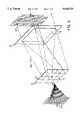
- FIG. 1shows the spatial power or energy distribution of a beam incident upon a homogenizer of the present invention and how the portions of the incident beam that are transmitted through the homogenizer are constituted at an output plane to produce an output beam having a substantially uniform spatial power or energy distribution and a second collimating hologram that is used to collimate the output beam.
- Thisrepresents the input characteristic of an inert gas-halide laser, popularly known as an eximer laser.
- FIG. 2shows the spatial power or energy distribution of an incident beam that is typical of a CO 2 or He-Ne laser incident on a homogenizer and the resulting collimated output beam.
- FIG. 3shows yet another spatial power or energy distribution of an incident beam that is typical of a Nd:YAG laser with a stable resonator optics incident on a homogenizer and the resultant collimated output beam.
- FIG. 1An optical beam is incident on a homogenizer 10 having an array 11 facets 12. Each of these facets 12 is constructed to direct any portion of an incident optical beam 14 that is incident thereupon uniformly over an entire target 16 at an output plane 18. As the portion of the incident beam transmitted through each of the facets 12 (shown illustratively as 20a and 20b) overlap at the target 16, the incident optical beam is mixed, thereby homogenizing the discrete portions of the incident beam 14 that are transmitted through each facet 12. This homogenization assures that at the target 16 there is a uniform mix of the incident beam 14, such that at the output plane 18 the output beam 22 has a uniform spatial power or energy distribution 24. The homogenization process averages the spatial power or energy distribution of the incident beam 14 with some losses due to inefficiencies.
- the incident optical beam 14emanates from an optical source (not shown), such as a laser, and is preferably in a collimated state, the spatial power or energy distribution of the incident beam may take on various forms, some of which are illustrated in FIGS. 1-3.
- the incident optical beam 14may be transferred to the homogenizer 10 from the optical source and collimated by way of conventional bulk optical elements, such as lenses and mirrors or through the use of holographic elements that produce the same results as conventional optical elements.
- the incident beam 14has a spatial power or energy distribution 26 that may have a significant variation across its cross-section. In some sources the spatial power or energy distribution 26 could vary significantly. For example in a gaussian beam this variation is typically 1/e, or 64% of the peak value.
- the power or energy distribution 26 of the incident beam 14may also change.
- the beam homogenizer 10is constructed to blend the incident optical beam 14 so that at the target 16 of the output plane 18 the output beam 22 will have an essentially uniform spatial power or energy distribution 24, independent of any variation in the spatial power or energy distribution 26 of the incident beam 14 and regardless of slight variation in where the incident beam 14 falls on the array 11.
- the spatial power or energy distribution 24 at the target 16will be essentially an average of the power or energy transmitted by each facet 12 rather than the power uniformity 26 of the incident signal 14.
- the beam homogenizer 10 in this embodimentis a holographic element and the facets 12 are sub-holograms, shown in FIG. 1 as a M ⁇ N linear array of equal sized sub-holograms. It is also envisioned that the sub-holograms may be of different sizes. These sub-holograms 12 are constructed to diffract any portion of the incident optical beam 14 that is incident thereupon over the entire target 16 at the output plane 18. Each of these sub-holograms 12 is a distinct diffractive grating that will direct the portion of the incident beam 14 over the entire target 16.
- the homogenizer 10is shown as a four-by-four array 11 for clarity of illustration and ease of description, while in reality, as described below, there may be substantially more sub-holograms 12, or facets, making up the homogenizer 10.
- the wavelength of the laser the output of which is to be reconstructedmust be used to create the holograms unless some complicated and costly techniques are employed. This severely limits the wavelength of laser that can be used, and particularly eliminates the more practical laser sources such as CO 2 , Nd:YAG and Eximer lasers.
- the materialcan be made of silicon, fused silica or quartz. These have low absorptivity and high damage thresholds for lasers in appropriate wavelength regions.
- the wavelength that the laser is to operateis a part of the computer generated hologram design and can easily handle from the UV region to the far infrared.
- CGHComputer Generated Holograms
- CGHsare usually surface-relief in nature and CGHs are formed using photolithographic, etching, electron-beam writing or other techniques.
- the electron-beam technologyprovides resolution close to that of optical film, but contains amplitude and phase quantization levels that are much coarser.
- Photolithographic procedurescan provide multilevel holograms; however, alignment error between the layers increases with the number of layers.
- the subhologramswith an iterative encoding method such as Iterative Discrete On-axis (IDO) encoding.
- IDOIterative Discrete On-axis
- This methodis more fully described in the publication entitled Iterative Encoding of High-Efficiency Holograms for Generation of Spot Arrays, Optics Letters, Vol. 14, pp. 479-81, 1989 by co-inventor Feldman et al. the disclosure of which is hereby incorporated by reference. Briefly, the hologram is divided into a two-dimensional array of rectangular cells and transmittance values for each cell is chosen and then optimized until an acceptable image is obtained. During the optimization process, the image, including interference effects between different facets, is monitored.
- the transmittance values for each cellis chosen to not only spread the light illuminating each facet over a large portion of (or the entire) output plane, but also to minimize the interference effects among the facets. Since on-axis encoding does not require a carrier wavefront for the hologram to function, these holograms can produce CGH's with much higher diffraction efficiencies than off-axis methods which do require a carrier wavefront. This is because holograms have a practical upper limit to the available Space-Bandwidth Product (SBP), or information contained in the CGH, that can be used to encode the desired image. When no information is required for a carrier wavefront, more information may be encoded relative to the desired image.
- SBPSpace-Bandwidth Product
- phase skippingoccurs when two adjacent CGH pixels have phase levels that differ by more than one phase level but less than by N-1 phase levels. Note that phase skipping does not occur when binary or multi-level gratings are employed such as those described in U.S. Pat. No. 4,547,037.
- the incident optical beam 14is assumed to have an elliptical form of 2.5 cm by 1 cm (centimeter) with a wavelength of 308 nm ⁇ 1 nm (nanometer).
- the target 16, or output beam 22could take on a number of shapes including circular or square and in particular in this described example the diameter at the output plane 18 is selected to be 1.5 cm. Under these conditions, the maximum deflection angle of the beam homogenizer 10 will be 2.9° if the spacing between homogenizer 10 and the target 16 on the output plane 18 is 20 cm.
- a maximum spatial frequency of 160 lp/mm(line-pairs/millimeter) is required.
- the CGHs that make up the homogenizermust have high diffraction efficiency. A diffraction efficiency of approximately 80% to 90% would be obtainable if the CGH spatial frequency is 800 lp/mm, or approximately five times the maximum spatial frequency required.
- the CGH spatial frequency of 800 lp/mmcorresponds to a CGH minimum feature size of 0.6 ⁇ m (micrometer)
- SAPSpace Bandwidth Product
- SAPis the number of pixels in the subhologram. It is also a measure of degrees of freedom. In general, a large number of degrees of freedom are needed to implement arbitrary optical functions with high efficiencies. This places a lower boundary on the dimensions of each of the subholograms of 77 ⁇ m ⁇ 77 ⁇ m. With the dimensions of each subhologram set to 100 ⁇ m ⁇ 100 ⁇ Ma a 100 ⁇ 100 facet array is of sufficient size to be used with the beam of the present example. These particular parameters yield a SAP of 167 ⁇ 167 well above the projected minimum SAP of 128 ⁇ 128 required for a diffraction efficiency between 80-90%. The calculated final diffraction efficiency for this device is projected to be between 85% and 95%.
- each sub-hologram 12will cover the entire target 16 at the output plane 18 and form the homogenized output beam 22. It is anticipated that the output beam 22 diameter will be 1.5 cm ⁇ 1.5 cm. In this case the output beam 22 is of a smaller diameter than the input beam 14. It would also be possible for the output beam 22 to be expanded by the homogenizer 10 such that the target 16 will have a larger cross-section than the input beam 14 or any arbitrary profile desired.
- the output plane 18represents an area in space rather than any particular element. It would be possible to place a bulk optical element, an optical fiber, another hologram, such as the collimating hologram shown in FIG. 1, an active device or any other apparatus that would make use of the output beam, such as a blocking mask or an object to be illuminated. One such application would be to incorporate an optical element, such as the collimating hologram 28 shown in the FIG. 1, at the output plane 18 that would enable the output beam to be used in laser cutting machines. In the absence of the homogenizer 10, a beam used in laser cutting applications has the intensity distribution of the incident beam 24 or a significant amount of the power or energy of the incident beam will be lost by passing the beam through an aperture. As shown in FIG.
- the wavefront of the incident beamhas a higher power center section, or "hotspot", that will cut through material faster than the lesser power outer fringe section. This makes for less accurately cut edges since the edge would take on a shape that approximates the reciprocal of the wavefront of the incident beam power distribution.
- the power distribution of the output wavefront at the targetillustrates the crisp power difference between off-target and on-target intensities of the homogenized beam. With the homogenized intensity distribution of the homogenized beam, cutting occurs more uniformly across the output beam to produce a more accurate edge.
Landscapes
- Physics & Mathematics (AREA)
- Optics & Photonics (AREA)
- Engineering & Computer Science (AREA)
- General Physics & Mathematics (AREA)
- Plasma & Fusion (AREA)
- Mechanical Engineering (AREA)
- Diffracting Gratings Or Hologram Optical Elements (AREA)
- Holo Graphy (AREA)
Abstract
Description
Claims (10)
Priority Applications (10)
| Application Number | Priority Date | Filing Date | Title |
|---|---|---|---|
| US08/203,188US5610733A (en) | 1994-02-28 | 1994-02-28 | Beam-homogenizer |
| FR9502259AFR2716726A1 (en) | 1994-02-28 | 1995-02-27 | Beam homogenizer. |
| JP7039879AJPH0894839A (en) | 1994-02-28 | 1995-02-28 | Light beam converter |
| US08/770,524US5850300A (en) | 1994-02-28 | 1996-12-20 | Diffractive beam homogenizer having free-form fringes |
| US09/160,322US6025938A (en) | 1994-02-28 | 1998-09-25 | Beam homogenizer |
| US09/240,611US6392808B1 (en) | 1994-02-28 | 1999-02-01 | Broad band controlled angle analog diffuser and associated methods |
| US09/484,050US6278550B1 (en) | 1994-02-28 | 2000-01-18 | Beam homogenizer |
| US09/902,740US6396635B2 (en) | 1994-02-28 | 2001-07-12 | Beam shaping element for use in a lithographic system |
| US10/155,178US6847485B2 (en) | 1994-02-28 | 2002-05-28 | Beam shaping element for use in a lithographic system |
| US11/034,050US6970292B2 (en) | 1994-02-28 | 2005-01-13 | Beam shaping element for use in a lithographic system |
Applications Claiming Priority (1)
| Application Number | Priority Date | Filing Date | Title |
|---|---|---|---|
| US08/203,188US5610733A (en) | 1994-02-28 | 1994-02-28 | Beam-homogenizer |
Related Child Applications (1)
| Application Number | Title | Priority Date | Filing Date |
|---|---|---|---|
| US08/770,524Continuation-In-PartUS5850300A (en) | 1994-02-28 | 1996-12-20 | Diffractive beam homogenizer having free-form fringes |
Publications (1)
| Publication Number | Publication Date |
|---|---|
| US5610733Atrue US5610733A (en) | 1997-03-11 |
Family
ID=22752880
Family Applications (1)
| Application Number | Title | Priority Date | Filing Date |
|---|---|---|---|
| US08/203,188Expired - LifetimeUS5610733A (en) | 1994-02-28 | 1994-02-28 | Beam-homogenizer |
Country Status (3)
| Country | Link |
|---|---|
| US (1) | US5610733A (en) |
| JP (1) | JPH0894839A (en) |
| FR (1) | FR2716726A1 (en) |
Cited By (54)
| Publication number | Priority date | Publication date | Assignee | Title |
|---|---|---|---|---|
| WO1998048312A1 (en)* | 1997-04-22 | 1998-10-29 | Minnesota Mining And Manufacturing Company | Prismatic light beam homogenizer for projection displays |
| US5850300A (en)* | 1994-02-28 | 1998-12-15 | Digital Optics Corporation | Diffractive beam homogenizer having free-form fringes |
| WO1999028077A3 (en)* | 1997-12-02 | 1999-07-15 | Rodenstock Instr | Device for homogenizing a beam of light or laser beam |
| WO1999039410A1 (en) | 1998-01-29 | 1999-08-05 | Visx, Incorporated | Laser delivery system and method with diffractive optic beam integration |
| US5982954A (en)* | 1996-10-21 | 1999-11-09 | University Technology Corporation | Optical field propagation between tilted or offset planes |
| US5986807A (en)* | 1997-01-13 | 1999-11-16 | Xerox Corporation | Single binary optical element beam homogenizer |
| US6008941A (en)* | 1996-06-25 | 1999-12-28 | Digital Optics Corporation | Optical soft aperture and use thereof |
| US6014260A (en)* | 1995-08-11 | 2000-01-11 | Societe De Production Et De Recherches Appliquees | Optical device for homogenizing a laser beam |
| WO2000003286A1 (en)* | 1998-07-09 | 2000-01-20 | Minnesota Mining And Manufacturing Company | Diffractive homogenizer with compensation for finite spatial coherence |
| WO2000008519A3 (en)* | 1998-08-04 | 2000-06-15 | Sharp Kk | A reflective display device and a light source for a display device |
| US6111670A (en)* | 1996-12-20 | 2000-08-29 | Denso Corporation | Hologram device and method for producing the same |
| US6118559A (en)* | 1996-12-20 | 2000-09-12 | Digital Optics Corporation | Broadband diffractive diffuser and associated methods |
| US6120976A (en)* | 1998-11-20 | 2000-09-19 | 3M Innovative Properties Company | Laser ablated feature formation method |
| US6172329B1 (en) | 1998-11-23 | 2001-01-09 | Minnesota Mining And Manufacturing Company | Ablated laser feature shape reproduction control |
| WO2001004685A1 (en)* | 1999-07-09 | 2001-01-18 | Deutsche Telekom Ag | Method and device for shaping the intensity profile of a laser beam |
| US6313435B1 (en) | 1998-11-20 | 2001-11-06 | 3M Innovative Properties Company | Mask orbiting for laser ablated feature formation |
| US6331177B1 (en) | 1998-04-17 | 2001-12-18 | Visx, Incorporated | Multiple beam laser sculpting system and method |
| US6392808B1 (en) | 1994-02-28 | 2002-05-21 | Digital Optics Corporation | Broad band controlled angle analog diffuser and associated methods |
| US20020159152A1 (en)* | 2001-04-27 | 2002-10-31 | Asml Us, Inc. | Apparatus for optical beam shaping and diffusing and associated methods |
| US20030125718A1 (en)* | 1998-04-17 | 2003-07-03 | Visx, Incorporated | Multiple beam laser sculpting system and method |
| WO2002010855A3 (en)* | 2000-08-01 | 2003-07-31 | Riake Corp | Illumination device and method for laser projector |
| US20030142378A1 (en)* | 1996-08-07 | 2003-07-31 | Cambridge University Technical Services Limited | Apparatus for optical communications |
| US20030215180A1 (en)* | 2002-05-17 | 2003-11-20 | Dimas Chris F. | Radiation power demultiplexer |
| US20040046758A1 (en)* | 2000-11-07 | 2004-03-11 | Cameron Collin D. | Three dimensional display |
| US20040114035A1 (en)* | 1998-03-24 | 2004-06-17 | Timothy White | Focusing panel illumination method and apparatus |
| US20050275939A1 (en)* | 2004-06-11 | 2005-12-15 | Ulrich Sander | Illumination apparatus, in particular slit lamp |
| US20060028732A1 (en)* | 2004-08-06 | 2006-02-09 | Visx, Incorporated | Lenslet array for beam homogenization |
| US7058306B1 (en) | 2001-01-24 | 2006-06-06 | Ball Aerospace & Technologies Corp. | Asymmetrical laser communication transceiver configuration |
| US7072591B1 (en) | 1999-06-23 | 2006-07-04 | Ball Aerospace & Technologies Corp. | Processing of multiple wavelength signals transmitted through free space |
| US20070014123A1 (en)* | 2005-07-12 | 2007-01-18 | Cianciotto Frank T | Tri-to-hex light mixing and homogenizing apparatus and method |
| US7177550B1 (en) | 2001-01-24 | 2007-02-13 | Ball Aerospace & Technologies Corp. | On-axis laser receiver wavelength demultiplexer with integral immersion lensed detectors |
| US20070147065A1 (en)* | 2005-12-28 | 2007-06-28 | Seiko Epson Corporation | Lighting device and projector |
| US20070212859A1 (en)* | 2006-03-08 | 2007-09-13 | Paul Carey | Method of thermal processing structures formed on a substrate |
| US20070217013A1 (en)* | 2006-03-14 | 2007-09-20 | Carl Zeiss Smt Ag | Optical system of an illumination device of a projection exposure apparatus |
| US20070291027A1 (en)* | 2000-11-07 | 2007-12-20 | F. Poszat Hu, Llc | Computer generated hologram display system |
| US20080025354A1 (en)* | 2006-07-31 | 2008-01-31 | Dean Jennings | Ultra-Fast Beam Dithering with Surface Acoustic Wave Modulator |
| US20080044809A1 (en)* | 2005-11-15 | 2008-02-21 | Shu-Ling Cheng | Detection method for human pappilomavirus (hpv) and its application in cervical cancer |
| US20080062242A1 (en)* | 2006-09-12 | 2008-03-13 | Hewlett-Packard Development Company, L.P. | Optical print head with non-Gaussian irradiance |
| US20080200344A1 (en)* | 2005-11-15 | 2008-08-21 | Shu-Ling Cheng | Protein chips for HPV detection |
| US20080266658A1 (en)* | 2004-11-24 | 2008-10-30 | Battelle Memorial Institute | Optical system for cell imaging |
| US20080292259A1 (en)* | 2007-02-01 | 2008-11-27 | The Boeing Company | Multi-color curved multi-light generating apparatus |
| US20090032511A1 (en)* | 2007-07-31 | 2009-02-05 | Adams Bruce E | Apparatus and method of improving beam shaping and beam homogenization |
| US20090059394A1 (en)* | 2007-08-29 | 2009-03-05 | Scaggs Michael J | Method for homogenizing light |
| US7548364B2 (en) | 2006-07-31 | 2009-06-16 | Applied Materials, Inc. | Ultra-fast beam dithering with surface acoustic wave modulator |
| US20090311668A1 (en)* | 2008-06-13 | 2009-12-17 | Shuling Cheng | In situ detection of early stages and late stages HPV einfection |
| US20100120019A1 (en)* | 2008-11-12 | 2010-05-13 | Shuling Cheng | Detection, screening, and diagnosis of HPV-associated cancers |
| US20110043917A1 (en)* | 2009-08-19 | 2011-02-24 | Lawrence Livermore National Security, Llc. | Diffractive laser beam homogenizer including a photo-active material and method of fabricating the same |
| US20110043900A1 (en)* | 2009-08-19 | 2011-02-24 | Lawrence Livermore National Security, Llc | Method and system for homogenizing diode laser pump arrays |
| US8916342B2 (en) | 2006-11-13 | 2014-12-23 | Oncohealth Corp. | Identification of high grade or ≧ CIN2 for early stages and late stages detection, screening, and diagnosis of human papillomavirus (HPV) and HPV-associated cancers |
| US9128094B2 (en) | 2010-01-08 | 2015-09-08 | Oncohealth Corp. | High throughput cell-based HPV immunoassays for diagnosis and screening of HPV-associated cancers |
| US9331452B2 (en) | 2009-08-19 | 2016-05-03 | Lawrence Livermore National Security, Llc | Method and system for homogenizing diode laser pump arrays |
| EP2527920B1 (en)* | 2007-10-12 | 2017-08-30 | Nikon Corporation | Illumination optical apparatus, exposure apparatus, and device manufacturing method |
| US10012544B2 (en) | 2016-11-29 | 2018-07-03 | Cymer, Llc | Homogenization of light beam for spectral feature metrology |
| US11973319B2 (en) | 2017-11-17 | 2024-04-30 | Uab Brolis Semiconductors | Radiant beam combining of multiple multimode semiconductor laser diodes for directional laser beam delivery applications |
Families Citing this family (7)
| Publication number | Priority date | Publication date | Assignee | Title |
|---|---|---|---|---|
| EP0788006A3 (en)* | 1996-02-01 | 2000-03-01 | Texas Instruments Incorporated | Improvements in or relating to spatial light modulators |
| JP2003270585A (en)* | 2002-03-18 | 2003-09-25 | Ricoh Co Ltd | Laser illumination optical system and exposure apparatus, laser processing apparatus, and projection apparatus using the same |
| JP2004257737A (en)* | 2003-02-24 | 2004-09-16 | Mitsui Eng & Shipbuild Co Ltd | Biochip reader |
| JP4174003B2 (en)* | 2003-03-28 | 2008-10-29 | 三井造船株式会社 | Spectroscopic identification and quantification system |
| KR100565076B1 (en)* | 2004-08-05 | 2006-03-30 | 삼성전자주식회사 | Illumination system without laser spots and projection system |
| JP6041093B2 (en)* | 2012-07-06 | 2016-12-07 | 大日本印刷株式会社 | Hologram reproduction device, hologram reproduction method, and projection-type image display device |
| JP6331254B2 (en)* | 2013-03-27 | 2018-05-30 | セイコーエプソン株式会社 | projector |
Citations (13)
| Publication number | Priority date | Publication date | Assignee | Title |
|---|---|---|---|---|
| US4170396A (en)* | 1975-04-14 | 1979-10-09 | Siemens Aktiengesellschaft | Optical component element |
| US4410237A (en)* | 1980-09-26 | 1983-10-18 | Massachusetts Institute Of Technology | Method and apparatus for shaping electromagnetic beams |
| US4455061A (en)* | 1980-07-31 | 1984-06-19 | The Regents Of The University Of Minnesota | Multi-faceted holographic optical element and methods of making and using same |
| US4547037A (en)* | 1980-10-16 | 1985-10-15 | Regents Of The University Of Minnesota | Holographic method for producing desired wavefront transformations |
| US4682841A (en)* | 1981-06-15 | 1987-07-28 | Afian Viktor V | Light radiation concentrator and method of making the same |
| US4979791A (en)* | 1989-12-08 | 1990-12-25 | Amp Incorporated | Laser diode connector assembly |
| US5061025A (en)* | 1990-04-13 | 1991-10-29 | Eastman Kodak Company | Hologon scanner with beam shaping stationary diffraction grating |
| US5075800A (en)* | 1989-12-04 | 1991-12-24 | Yeda Research And Development Co. Ltd. | Method of optimizing holographic optical elements |
| US5117476A (en)* | 1990-01-19 | 1992-05-26 | Amp Incorporated | Optical transceiver package with insertable subassembly |
| US5202775A (en)* | 1991-11-04 | 1993-04-13 | University Of North Carolina | Radically symmetric hologram and method of fabricating the same |
| US5289298A (en)* | 1992-12-22 | 1994-02-22 | Hughes Aircraft Company | Multiplex grating holographic floodlit center high mounted stoplight |
| US5315427A (en)* | 1992-12-14 | 1994-05-24 | Xerox Corporation | Pair of binary diffraction optics for use in overfilled raster output scanning systems |
| US5361149A (en)* | 1991-03-20 | 1994-11-01 | Fujitsu Limited | Optimized design method for holographic optical element and apparatus using such holographic optical element |
- 1994
- 1994-02-28USUS08/203,188patent/US5610733A/ennot_activeExpired - Lifetime
- 1995
- 1995-02-27FRFR9502259Apatent/FR2716726A1/enactiveGranted
- 1995-02-28JPJP7039879Apatent/JPH0894839A/ennot_activeWithdrawn
Patent Citations (13)
| Publication number | Priority date | Publication date | Assignee | Title |
|---|---|---|---|---|
| US4170396A (en)* | 1975-04-14 | 1979-10-09 | Siemens Aktiengesellschaft | Optical component element |
| US4455061A (en)* | 1980-07-31 | 1984-06-19 | The Regents Of The University Of Minnesota | Multi-faceted holographic optical element and methods of making and using same |
| US4410237A (en)* | 1980-09-26 | 1983-10-18 | Massachusetts Institute Of Technology | Method and apparatus for shaping electromagnetic beams |
| US4547037A (en)* | 1980-10-16 | 1985-10-15 | Regents Of The University Of Minnesota | Holographic method for producing desired wavefront transformations |
| US4682841A (en)* | 1981-06-15 | 1987-07-28 | Afian Viktor V | Light radiation concentrator and method of making the same |
| US5075800A (en)* | 1989-12-04 | 1991-12-24 | Yeda Research And Development Co. Ltd. | Method of optimizing holographic optical elements |
| US4979791A (en)* | 1989-12-08 | 1990-12-25 | Amp Incorporated | Laser diode connector assembly |
| US5117476A (en)* | 1990-01-19 | 1992-05-26 | Amp Incorporated | Optical transceiver package with insertable subassembly |
| US5061025A (en)* | 1990-04-13 | 1991-10-29 | Eastman Kodak Company | Hologon scanner with beam shaping stationary diffraction grating |
| US5361149A (en)* | 1991-03-20 | 1994-11-01 | Fujitsu Limited | Optimized design method for holographic optical element and apparatus using such holographic optical element |
| US5202775A (en)* | 1991-11-04 | 1993-04-13 | University Of North Carolina | Radically symmetric hologram and method of fabricating the same |
| US5315427A (en)* | 1992-12-14 | 1994-05-24 | Xerox Corporation | Pair of binary diffraction optics for use in overfilled raster output scanning systems |
| US5289298A (en)* | 1992-12-22 | 1994-02-22 | Hughes Aircraft Company | Multiplex grating holographic floodlit center high mounted stoplight |
Non-Patent Citations (10)
| Title |
|---|
| Holographic optics: for when less is more -- Sunny Bains -- Laser Focus World, Apr. 1993-pp. 151-156. |
| Holographic optics: for when less is more Sunny Bains Laser Focus World, Apr. 1993 pp. 151 156.* |
| Iterative encoding of high efficiency holograms for generation of spot arrays Michael R. Feldman and Clark C. Guest Optics Letters /vol. 14, No. 10/May 15, 1989 pp. 479 481.* |
| Iterative encoding of high-efficiency holograms for generation of spot arrays -Michael R. Feldman and Clark C. Guest--Optics Letters/vol. 14, No. 10/May 15, 1989 -- pp. 479-481. |
| J. Cederquist, et al., "Computer-Generated Holograms for Geometric Transformations", Applied Optics, vol. 23, No. 18, Sep. 1984, pp. 3099-3104. |
| J. Cederquist, et al., Computer Generated Holograms for Geometric Transformations , Applied Optics, vol. 23, No. 18, Sep. 1984, pp. 3099 3104.* |
| M. A. Golub, et al., "Focusing Light into a Specified Volume by Computer-Synthesized Holograms" Sov. Tech. Phys. Lett. 7(5) May 1981. |
| M. A. Golub, et al., Focusing Light into a Specified Volume by Computer Synthesized Holograms Sov. Tech. Phys. Lett. 7(5) May 1981.* |
| Y. H. Wu, et al., "Cell-Oriented On-Axis Computer-Generated Holograms for use in the Fresnel Diffraction Mode" Applied Optics, vol. 23, No. 2 15 Jan. 1984. |
| Y. H. Wu, et al., Cell Oriented On Axis Computer Generated Holograms for use in the Fresnel Diffraction Mode Applied Optics, vol. 23, No. 2 15 Jan. 1984.* |
Cited By (120)
| Publication number | Priority date | Publication date | Assignee | Title |
|---|---|---|---|---|
| US6025938A (en)* | 1994-02-28 | 2000-02-15 | Digital Optics Corporation | Beam homogenizer |
| US5850300A (en)* | 1994-02-28 | 1998-12-15 | Digital Optics Corporation | Diffractive beam homogenizer having free-form fringes |
| US6396635B2 (en) | 1994-02-28 | 2002-05-28 | Digital Optics Corporation | Beam shaping element for use in a lithographic system |
| US6392808B1 (en) | 1994-02-28 | 2002-05-21 | Digital Optics Corporation | Broad band controlled angle analog diffuser and associated methods |
| US6278550B1 (en) | 1994-02-28 | 2001-08-21 | Digital Optics Corporation | Beam homogenizer |
| US20040179269A1 (en)* | 1994-02-28 | 2004-09-16 | Kathman Alan D. | Beam shaping element for use in a lithographic system |
| US6847485B2 (en) | 1994-02-28 | 2005-01-25 | Digital Optics Corp. | Beam shaping element for use in a lithographic system |
| US20050128540A1 (en)* | 1994-02-28 | 2005-06-16 | Digital Optics Corporation | Beam shaping element for use in a lithographic system |
| US6970292B2 (en) | 1994-02-28 | 2005-11-29 | Digital Optics Corp. | Beam shaping element for use in a lithographic system |
| US6014260A (en)* | 1995-08-11 | 2000-01-11 | Societe De Production Et De Recherches Appliquees | Optical device for homogenizing a laser beam |
| US6008941A (en)* | 1996-06-25 | 1999-12-28 | Digital Optics Corporation | Optical soft aperture and use thereof |
| US20030142378A1 (en)* | 1996-08-07 | 2003-07-31 | Cambridge University Technical Services Limited | Apparatus for optical communications |
| US5982954A (en)* | 1996-10-21 | 1999-11-09 | University Technology Corporation | Optical field propagation between tilted or offset planes |
| US6330087B1 (en) | 1996-12-20 | 2001-12-11 | Denso Corporation | Hologram device and method for producing the same |
| US6111670A (en)* | 1996-12-20 | 2000-08-29 | Denso Corporation | Hologram device and method for producing the same |
| US6118559A (en)* | 1996-12-20 | 2000-09-12 | Digital Optics Corporation | Broadband diffractive diffuser and associated methods |
| US5986807A (en)* | 1997-01-13 | 1999-11-16 | Xerox Corporation | Single binary optical element beam homogenizer |
| US6024452A (en)* | 1997-04-22 | 2000-02-15 | 3M Innovative Properties Company | Prismatic light beam homogenizer for projection displays |
| WO1998048312A1 (en)* | 1997-04-22 | 1998-10-29 | Minnesota Mining And Manufacturing Company | Prismatic light beam homogenizer for projection displays |
| WO1999028077A3 (en)* | 1997-12-02 | 1999-07-15 | Rodenstock Instr | Device for homogenizing a beam of light or laser beam |
| WO1999039410A1 (en) | 1998-01-29 | 1999-08-05 | Visx, Incorporated | Laser delivery system and method with diffractive optic beam integration |
| US20040114035A1 (en)* | 1998-03-24 | 2004-06-17 | Timothy White | Focusing panel illumination method and apparatus |
| US6331177B1 (en) | 1998-04-17 | 2001-12-18 | Visx, Incorporated | Multiple beam laser sculpting system and method |
| US6638271B2 (en) | 1998-04-17 | 2003-10-28 | Visx, Inc. | Multiple beam laser sculpting system and method |
| US20030125718A1 (en)* | 1998-04-17 | 2003-07-03 | Visx, Incorporated | Multiple beam laser sculpting system and method |
| US6984227B2 (en) | 1998-04-17 | 2006-01-10 | Visx, Incorporated | Multiple beam laser sculpting system and method |
| US6072631A (en)* | 1998-07-09 | 2000-06-06 | 3M Innovative Properties Company | Diffractive homogenizer with compensation for spatial coherence |
| WO2000003286A1 (en)* | 1998-07-09 | 2000-01-20 | Minnesota Mining And Manufacturing Company | Diffractive homogenizer with compensation for finite spatial coherence |
| US6252714B1 (en) | 1998-07-09 | 2001-06-26 | 3M Innovative Properties Company | Diffractive homogenizer with compensation for spatial coherence |
| US6483613B1 (en)* | 1998-08-04 | 2002-11-19 | Sharp Kabushiki Kaisha | Reflective display device and a light source for a display device |
| WO2000008519A3 (en)* | 1998-08-04 | 2000-06-15 | Sharp Kk | A reflective display device and a light source for a display device |
| US6313435B1 (en) | 1998-11-20 | 2001-11-06 | 3M Innovative Properties Company | Mask orbiting for laser ablated feature formation |
| US6120976A (en)* | 1998-11-20 | 2000-09-19 | 3M Innovative Properties Company | Laser ablated feature formation method |
| US6172329B1 (en) | 1998-11-23 | 2001-01-09 | Minnesota Mining And Manufacturing Company | Ablated laser feature shape reproduction control |
| US7072591B1 (en) | 1999-06-23 | 2006-07-04 | Ball Aerospace & Technologies Corp. | Processing of multiple wavelength signals transmitted through free space |
| WO2001004685A1 (en)* | 1999-07-09 | 2001-01-18 | Deutsche Telekom Ag | Method and device for shaping the intensity profile of a laser beam |
| US6952296B1 (en) | 1999-07-09 | 2005-10-04 | Deutsche Telekom Ag | Method and device for forming the intensity profile of a laser beam |
| US6606173B2 (en) | 2000-08-01 | 2003-08-12 | Riake Corporation | Illumination device and method for laser projector |
| WO2002010855A3 (en)* | 2000-08-01 | 2003-07-31 | Riake Corp | Illumination device and method for laser projector |
| US20040046758A1 (en)* | 2000-11-07 | 2004-03-11 | Cameron Collin D. | Three dimensional display |
| US7417634B2 (en)* | 2000-11-07 | 2008-08-26 | F. Poszat Hu, Llc | Three dimensional display |
| US20070291027A1 (en)* | 2000-11-07 | 2007-12-20 | F. Poszat Hu, Llc | Computer generated hologram display system |
| US7649532B2 (en)* | 2000-11-07 | 2010-01-19 | Cameron Colin D | Computer generated hologram display system |
| US20070040829A1 (en)* | 2000-11-07 | 2007-02-22 | Qinetiq Limited | Three dimensional display |
| US7177550B1 (en) | 2001-01-24 | 2007-02-13 | Ball Aerospace & Technologies Corp. | On-axis laser receiver wavelength demultiplexer with integral immersion lensed detectors |
| US7058306B1 (en) | 2001-01-24 | 2006-06-06 | Ball Aerospace & Technologies Corp. | Asymmetrical laser communication transceiver configuration |
| US20080019004A1 (en)* | 2001-04-27 | 2008-01-24 | Asml Holding N.V. | Apparatus for optical beam shaping and associated methods |
| US7137714B2 (en) | 2001-04-27 | 2006-11-21 | Asml Holding N.V. | Apparatus for optical beam shaping and diffusing and associated methods |
| US7199929B2 (en) | 2001-04-27 | 2007-04-03 | Asml Holdings N.V. | Methods for optical beam shaping and diffusing |
| US7401931B2 (en) | 2001-04-27 | 2008-07-22 | Asml Holding N.V. | Apparatus for optical beam shaping and associated methods |
| US20050190451A1 (en)* | 2001-04-27 | 2005-09-01 | Asml Holding N.V. | Apparatus for optical beam shaping and diffusing and associated methods |
| US20020159152A1 (en)* | 2001-04-27 | 2002-10-31 | Asml Us, Inc. | Apparatus for optical beam shaping and diffusing and associated methods |
| US20030215180A1 (en)* | 2002-05-17 | 2003-11-20 | Dimas Chris F. | Radiation power demultiplexer |
| US6707964B2 (en) | 2002-05-17 | 2004-03-16 | Exfo Photonic Solutions Inc. | Radiation power demultiplexer |
| US7382529B2 (en)* | 2004-06-11 | 2008-06-03 | Leica Microsystems (Schweiz) Ag | Illumination apparatus, in particular slit lamp |
| US20050275939A1 (en)* | 2004-06-11 | 2005-12-15 | Ulrich Sander | Illumination apparatus, in particular slit lamp |
| US7206132B2 (en) | 2004-08-06 | 2007-04-17 | Visx, Incorporated | Lenslet array for beam homogenization |
| US7738176B2 (en) | 2004-08-06 | 2010-06-15 | Amo Manufacturing Usa Llc. | Lenslet array for beam homogenization |
| US20090122411A1 (en)* | 2004-08-06 | 2009-05-14 | Amo Manufacturing Usa, Llc | Lenslet array for beam homogenization |
| US20060028732A1 (en)* | 2004-08-06 | 2006-02-09 | Visx, Incorporated | Lenslet array for beam homogenization |
| US7355794B2 (en) | 2004-08-06 | 2008-04-08 | Amo Manufacturing Usa, Llc | Lenslet array for beam homogenization |
| US7394595B2 (en) | 2004-08-06 | 2008-07-01 | Amo Manufacturing Usa, Llc | Lenslet array for beam homogenization |
| US7978405B2 (en) | 2004-11-24 | 2011-07-12 | Battelle Memorial Institute | Optical system for cell imaging |
| US20110194174A1 (en)* | 2004-11-24 | 2011-08-11 | Battelle Memorial Institute | Optical system for cell imaging |
| US20080266658A1 (en)* | 2004-11-24 | 2008-10-30 | Battelle Memorial Institute | Optical system for cell imaging |
| US7265906B2 (en)* | 2005-07-12 | 2007-09-04 | The Boeing Company | Tri-to-hex light mixing and homogenizing apparatus and method |
| US20070014123A1 (en)* | 2005-07-12 | 2007-01-18 | Cianciotto Frank T | Tri-to-hex light mixing and homogenizing apparatus and method |
| US7732166B2 (en) | 2005-11-15 | 2010-06-08 | Oncohealth Corporation | Detection method for human pappilomavirus (HPV) and its application in cervical cancer |
| US7972776B2 (en) | 2005-11-15 | 2011-07-05 | Oncohealth Corporation | Protein chips for HPV detection |
| US20080200344A1 (en)* | 2005-11-15 | 2008-08-21 | Shu-Ling Cheng | Protein chips for HPV detection |
| US20080044809A1 (en)* | 2005-11-15 | 2008-02-21 | Shu-Ling Cheng | Detection method for human pappilomavirus (hpv) and its application in cervical cancer |
| US20070147065A1 (en)* | 2005-12-28 | 2007-06-28 | Seiko Epson Corporation | Lighting device and projector |
| US8518838B2 (en) | 2006-03-08 | 2013-08-27 | Applied Materials, Inc. | Method of thermal processing structures formed on a substrate |
| US20070212859A1 (en)* | 2006-03-08 | 2007-09-13 | Paul Carey | Method of thermal processing structures formed on a substrate |
| US20070221640A1 (en)* | 2006-03-08 | 2007-09-27 | Dean Jennings | Apparatus for thermal processing structures formed on a substrate |
| US20100323532A1 (en)* | 2006-03-08 | 2010-12-23 | Paul Carey | Method of thermal processing structures formed on a substrate |
| US7569463B2 (en) | 2006-03-08 | 2009-08-04 | Applied Materials, Inc. | Method of thermal processing structures formed on a substrate |
| US10840100B2 (en) | 2006-03-08 | 2020-11-17 | Applied Materials, Inc. | Method of thermal processing structures formed on a substrate |
| US10141191B2 (en) | 2006-03-08 | 2018-11-27 | Applied Materials, Inc. | Method of thermal processing structures formed on a substrate |
| US20070218644A1 (en)* | 2006-03-08 | 2007-09-20 | Applied Materials, Inc. | Method of thermal processing structures formed on a substrate |
| US20070217013A1 (en)* | 2006-03-14 | 2007-09-20 | Carl Zeiss Smt Ag | Optical system of an illumination device of a projection exposure apparatus |
| US8068279B2 (en) | 2006-03-14 | 2011-11-29 | Carl Zeiss Smt Gmbh | Optical system of an illumination device of a projection exposure apparatus |
| US20080025354A1 (en)* | 2006-07-31 | 2008-01-31 | Dean Jennings | Ultra-Fast Beam Dithering with Surface Acoustic Wave Modulator |
| US7548364B2 (en) | 2006-07-31 | 2009-06-16 | Applied Materials, Inc. | Ultra-fast beam dithering with surface acoustic wave modulator |
| US20080062242A1 (en)* | 2006-09-12 | 2008-03-13 | Hewlett-Packard Development Company, L.P. | Optical print head with non-Gaussian irradiance |
| US8916342B2 (en) | 2006-11-13 | 2014-12-23 | Oncohealth Corp. | Identification of high grade or ≧ CIN2 for early stages and late stages detection, screening, and diagnosis of human papillomavirus (HPV) and HPV-associated cancers |
| US7603017B2 (en) | 2007-02-01 | 2009-10-13 | The Boeing Company | Multi-color curved multi-light generating apparatus |
| US20080292259A1 (en)* | 2007-02-01 | 2008-11-27 | The Boeing Company | Multi-color curved multi-light generating apparatus |
| US9908200B2 (en) | 2007-07-31 | 2018-03-06 | Applied Materials, Inc. | Apparatus and method of improving beam shaping and beam homogenization |
| US8829392B2 (en) | 2007-07-31 | 2014-09-09 | Applied Materials, Inc. | Apparatus and method of improving beam shaping and beam homogenization |
| US8148663B2 (en) | 2007-07-31 | 2012-04-03 | Applied Materials, Inc. | Apparatus and method of improving beam shaping and beam homogenization |
| US20090032511A1 (en)* | 2007-07-31 | 2009-02-05 | Adams Bruce E | Apparatus and method of improving beam shaping and beam homogenization |
| US7944624B2 (en) | 2007-08-29 | 2011-05-17 | Scaggs Michael J | Method for homogenizing light |
| US20090059394A1 (en)* | 2007-08-29 | 2009-03-05 | Scaggs Michael J | Method for homogenizing light |
| EP2527920B1 (en)* | 2007-10-12 | 2017-08-30 | Nikon Corporation | Illumination optical apparatus, exposure apparatus, and device manufacturing method |
| US10101666B2 (en) | 2007-10-12 | 2018-10-16 | Nikon Corporation | Illumination optical apparatus, exposure apparatus, and device manufacturing method |
| US20100009387A1 (en)* | 2008-06-13 | 2010-01-14 | Shuling Cheng | Detection of early stages and late stages HPV infection |
| US20100003704A1 (en)* | 2008-06-13 | 2010-01-07 | Shuling Cheng | IN SITU detection of early stages and late stages HPV infection |
| US20090311668A1 (en)* | 2008-06-13 | 2009-12-17 | Shuling Cheng | In situ detection of early stages and late stages HPV einfection |
| US9568474B2 (en) | 2008-06-13 | 2017-02-14 | Oncohealth Corp. | In situ detection of early stages and late stages HPV infection |
| US8859218B2 (en) | 2008-06-13 | 2014-10-14 | Oncohealth Corp. | In situ detection of early stages and late stages HPV infection |
| US8865162B2 (en) | 2008-06-13 | 2014-10-21 | Oncohealth Corp. | Monoclonal antibodies against HPV proteins |
| US8278056B2 (en) | 2008-06-13 | 2012-10-02 | Oncohealth Corp. | Detection of early stages and late stages HPV infection |
| US20090312527A1 (en)* | 2008-06-13 | 2009-12-17 | Neodiagnostic Labs Inc | Novel monoclonal antibodies against HPV proteins |
| US20100120019A1 (en)* | 2008-11-12 | 2010-05-13 | Shuling Cheng | Detection, screening, and diagnosis of HPV-associated cancers |
| US8968995B2 (en) | 2008-11-12 | 2015-03-03 | Oncohealth Corp. | Detection, screening, and diagnosis of HPV-associated cancers |
| US20110043917A1 (en)* | 2009-08-19 | 2011-02-24 | Lawrence Livermore National Security, Llc. | Diffractive laser beam homogenizer including a photo-active material and method of fabricating the same |
| US9331452B2 (en) | 2009-08-19 | 2016-05-03 | Lawrence Livermore National Security, Llc | Method and system for homogenizing diode laser pump arrays |
| US8547632B2 (en) | 2009-08-19 | 2013-10-01 | Lawrence Livermore National Security, Llc | Method and system for homogenizing diode laser pump arrays |
| US8728719B2 (en) | 2009-08-19 | 2014-05-20 | Lawrence Livermore National Security, Llc | Diffractive laser beam homogenizer including a photo-active material and method of fabricating the same |
| US20110043900A1 (en)* | 2009-08-19 | 2011-02-24 | Lawrence Livermore National Security, Llc | Method and system for homogenizing diode laser pump arrays |
| US9128094B2 (en) | 2010-01-08 | 2015-09-08 | Oncohealth Corp. | High throughput cell-based HPV immunoassays for diagnosis and screening of HPV-associated cancers |
| US10288484B2 (en) | 2016-11-29 | 2019-05-14 | Cymer, Llc | Homogenization of light beam for spectral feature metrology |
| US10012544B2 (en) | 2016-11-29 | 2018-07-03 | Cymer, Llc | Homogenization of light beam for spectral feature metrology |
| CN109964106A (en)* | 2016-11-29 | 2019-07-02 | 西默有限公司 | Beam Homogenization for Spectral Feature Metrology |
| KR20190082883A (en)* | 2016-11-29 | 2019-07-10 | 사이머 엘엘씨 | Homogenization of light beam for spectral feature measurement |
| TWI687662B (en)* | 2016-11-29 | 2020-03-11 | 美商希瑪有限責任公司 | Metrology system, method for measuring spectral feature of a light beam, and deep ultraviolet light source |
| WO2018102049A3 (en)* | 2016-11-29 | 2019-06-06 | Cymer, Llc | Homogenization of light beam for spectral feature metrology |
| CN109964106B (en)* | 2016-11-29 | 2022-08-26 | 西默有限公司 | Beam homogenization for spectral feature metrology |
| US11973319B2 (en) | 2017-11-17 | 2024-04-30 | Uab Brolis Semiconductors | Radiant beam combining of multiple multimode semiconductor laser diodes for directional laser beam delivery applications |
Also Published As
| Publication number | Publication date |
|---|---|
| JPH0894839A (en) | 1996-04-12 |
| FR2716726A1 (en) | 1995-09-01 |
| FR2716726B1 (en) | 1997-03-07 |
Similar Documents
| Publication | Publication Date | Title |
|---|---|---|
| US5610733A (en) | Beam-homogenizer | |
| US6025938A (en) | Beam homogenizer | |
| US5657138A (en) | Generating defined structures on materials using combined optical technologies for transforming the processing beam | |
| EP0843239B1 (en) | A method of fabricating a radially symmetric hologram | |
| WO2004031867A2 (en) | System and method for holographic fabrication and replication of diffractive optical elements for maskless lithography | |
| WO1997050011A2 (en) | Diffractive optical elements and use thereof | |
| Welch et al. | Iterative discrete on-axis encoding of radially symmetric computer-generated holograms | |
| Feldman et al. | Holograms for optical interconnects for very large scale integrated circuits fabricated by electron-beam lithography | |
| Shealy | History of beam shaping | |
| Danziger et al. | Multilevel diffractive elements for generalized wavefront shaping | |
| US4878718A (en) | Method for holographic correction of beams of coherent light | |
| Urquhart et al. | Diffractive lenses utilizing orthogonal cylindrical Fresnel zone plates | |
| Herzig et al. | Design and fabrication of diffractive optical elements for beam shaping and imaging | |
| Prongué et al. | HOE for clock distribution in integrated circuits: experimental results | |
| Hao et al. | Spatially inhomogeneous polarization in laser beam shaping | |
| Hasman et al. | Diffractive optics: design, realization, and applications | |
| Redmond et al. | High performance holographic optics for the visible and near infra-red | |
| Song et al. | Generation of multiple-pitch gratings in WDM devices by using a single computer-generated phase mask | |
| Brenner et al. | Design, analysis, and fabrication of refractive beam shaping elements for optical storage applications | |
| Bao et al. | Phase-only diffractive optical element for improving the beam quality of a vertical-cavity surface-emitting laser array | |
| Mait | Diffractive optics | |
| Finlan et al. | Collimation of diode laser arrays using etched cylindrical computer-generated holographic lenses | |
| Luo et al. | Implementation of crossover optical interconnect network with phase fresnel microlens arrays | |
| OMEGA | High-Efficiency Distributed Phase Plate Generation and Characterization | |
| Rossi et al. | Phase-matched Fresnel elements for fan-out applications |
Legal Events
| Date | Code | Title | Description |
|---|---|---|---|
| AS | Assignment | Owner name:CAROLINAS CAPITAL LIMITED PARTNERSHIP, NORTH CAROL Free format text:SECURITY INTEREST;ASSIGNOR:DIGITAL OPTICS CORPORATION;REEL/FRAME:007637/0703 Effective date:19950516 | |
| AS | Assignment | Owner name:DIGITAL OPTICS CORPORATION, NORTH CAROLINA Free format text:ASSIGNMENT OF ASSIGNORS INTEREST;ASSIGNOR:FELDMAN, MICHAEL R.;REEL/FRAME:008267/0316 Effective date:19961205 | |
| AS | Assignment | Owner name:WHITAKER CORPORATION, THE, DELAWARE Free format text:ASSIGNMENT OF ASSIGNORS INTEREST;ASSIGNOR:ROWLETTE, JOHN ROBERT, SR.;REEL/FRAME:008280/0792 Effective date:19961206 | |
| STCF | Information on status: patent grant | Free format text:PATENTED CASE | |
| FPAY | Fee payment | Year of fee payment:4 | |
| FEPP | Fee payment procedure | Free format text:PAYOR NUMBER ASSIGNED (ORIGINAL EVENT CODE: ASPN); ENTITY STATUS OF PATENT OWNER: LARGE ENTITY | |
| FPAY | Fee payment | Year of fee payment:8 | |
| FPAY | Fee payment | Year of fee payment:12 | |
| REMI | Maintenance fee reminder mailed | ||
| AS | Assignment | Owner name:TESSERA NORTH AMERICA, INC., NORTH CAROLINA Free format text:CHANGE OF NAME;ASSIGNOR:DIGITAL OPTICS CORPORATION;REEL/FRAME:024697/0727 Effective date:20070330 | |
| AS | Assignment | Owner name:DIGITALOPTICS CORPORATION EAST, NORTH CAROLINA Free format text:CHANGE OF NAME;ASSIGNOR:TESSERA NORTH AMERICA, INC.;REEL/FRAME:027768/0541 Effective date:20110701 | |
| AS | Assignment | Owner name:DIGITALOPTICS CORPORATION EAST, NORTH CAROLINA Free format text:TERMINATION OF SECURITY INTEREST;ASSIGNOR:CAROLINAS CAPITAL LIMITED PARTNERSHIP;REEL/FRAME:029885/0143 Effective date:20130206 | |
| AS | Assignment | Owner name:FLIR SYSTEMS TRADING BELGIUM BVBA, BELGIUM Free format text:ASSIGNMENT OF ASSIGNORS INTEREST;ASSIGNOR:DIGITALOPTICS CORPORATION EAST;REEL/FRAME:032827/0362 Effective date:20130808 | |
| AS | Assignment | Owner name:AVAGO TECHNOLOGIES GENERAL IP (SINGAPORE) PTE. LTD Free format text:ASSIGNMENT OF ASSIGNORS INTEREST;ASSIGNOR:FLIR SYSTEMS TRADING BELGIUM BVBA;REEL/FRAME:036126/0092 Effective date:20140827 | |
| AS | Assignment | Owner name:DIGITALOPTICS CORPORATION EAST, NORTH CAROLINA Free format text:CORRECTIVE ASSIGNMENT TO CORRECT THE PATENT NO. 7817833 PREVIOUSLY RECORDED AT REEL: 027768 FRAME: 0541. ASSIGNOR(S) HEREBY CONFIRMS THE ASSIGNMENT;ASSIGNOR:TESSERA NORTH AMERICA, INC.;REEL/FRAME:036733/0896 Effective date:20110701 |