US5609770A - Graphical operator machine interface and method for information entry and selection in a dialysis machine - Google Patents
Graphical operator machine interface and method for information entry and selection in a dialysis machineDownload PDFInfo
- Publication number
- US5609770A US5609770AUS08/486,944US48694495AUS5609770AUS 5609770 AUS5609770 AUS 5609770AUS 48694495 AUS48694495 AUS 48694495AUS 5609770 AUS5609770 AUS 5609770A
- Authority
- US
- United States
- Prior art keywords
- parameters
- screen
- dialysis machine
- machine
- selected group
- Prior art date
- Legal status (The legal status is an assumption and is not a legal conclusion. Google has not performed a legal analysis and makes no representation as to the accuracy of the status listed.)
- Expired - Lifetime
Links
Images


Classifications
- A—HUMAN NECESSITIES
- A61—MEDICAL OR VETERINARY SCIENCE; HYGIENE
- A61M—DEVICES FOR INTRODUCING MEDIA INTO, OR ONTO, THE BODY; DEVICES FOR TRANSDUCING BODY MEDIA OR FOR TAKING MEDIA FROM THE BODY; DEVICES FOR PRODUCING OR ENDING SLEEP OR STUPOR
- A61M1/00—Suction or pumping devices for medical purposes; Devices for carrying-off, for treatment of, or for carrying-over, body-liquids; Drainage systems
- A61M1/14—Dialysis systems; Artificial kidneys; Blood oxygenators ; Reciprocating systems for treatment of body fluids, e.g. single needle systems for hemofiltration or pheresis
- A61M1/16—Dialysis systems; Artificial kidneys; Blood oxygenators ; Reciprocating systems for treatment of body fluids, e.g. single needle systems for hemofiltration or pheresis with membranes
- A—HUMAN NECESSITIES
- A61—MEDICAL OR VETERINARY SCIENCE; HYGIENE
- A61M—DEVICES FOR INTRODUCING MEDIA INTO, OR ONTO, THE BODY; DEVICES FOR TRANSDUCING BODY MEDIA OR FOR TAKING MEDIA FROM THE BODY; DEVICES FOR PRODUCING OR ENDING SLEEP OR STUPOR
- A61M1/00—Suction or pumping devices for medical purposes; Devices for carrying-off, for treatment of, or for carrying-over, body-liquids; Drainage systems
- A61M1/36—Other treatment of blood in a by-pass of the natural circulatory system, e.g. temperature adaptation, irradiation ; Extra-corporeal blood circuits
- A61M1/3621—Extra-corporeal blood circuits
- A61M1/3622—Extra-corporeal blood circuits with a cassette forming partially or totally the blood circuit
- A61M1/36222—Details related to the interface between cassette and machine
- A—HUMAN NECESSITIES
- A61—MEDICAL OR VETERINARY SCIENCE; HYGIENE
- A61M—DEVICES FOR INTRODUCING MEDIA INTO, OR ONTO, THE BODY; DEVICES FOR TRANSDUCING BODY MEDIA OR FOR TAKING MEDIA FROM THE BODY; DEVICES FOR PRODUCING OR ENDING SLEEP OR STUPOR
- A61M1/00—Suction or pumping devices for medical purposes; Devices for carrying-off, for treatment of, or for carrying-over, body-liquids; Drainage systems
- A61M1/36—Other treatment of blood in a by-pass of the natural circulatory system, e.g. temperature adaptation, irradiation ; Extra-corporeal blood circuits
- A61M1/3621—Extra-corporeal blood circuits
- A61M1/3622—Extra-corporeal blood circuits with a cassette forming partially or totally the blood circuit
- A61M1/36225—Extra-corporeal blood circuits with a cassette forming partially or totally the blood circuit with blood pumping means or components thereof
- A—HUMAN NECESSITIES
- A61—MEDICAL OR VETERINARY SCIENCE; HYGIENE
- A61M—DEVICES FOR INTRODUCING MEDIA INTO, OR ONTO, THE BODY; DEVICES FOR TRANSDUCING BODY MEDIA OR FOR TAKING MEDIA FROM THE BODY; DEVICES FOR PRODUCING OR ENDING SLEEP OR STUPOR
- A61M1/00—Suction or pumping devices for medical purposes; Devices for carrying-off, for treatment of, or for carrying-over, body-liquids; Drainage systems
- A61M1/36—Other treatment of blood in a by-pass of the natural circulatory system, e.g. temperature adaptation, irradiation ; Extra-corporeal blood circuits
- A61M1/3621—Extra-corporeal blood circuits
- A61M1/3622—Extra-corporeal blood circuits with a cassette forming partially or totally the blood circuit
- A61M1/36226—Constructional details of cassettes, e.g. specific details on material or shape
- A61M1/362262—Details of incorporated reservoirs
- A—HUMAN NECESSITIES
- A61—MEDICAL OR VETERINARY SCIENCE; HYGIENE
- A61M—DEVICES FOR INTRODUCING MEDIA INTO, OR ONTO, THE BODY; DEVICES FOR TRANSDUCING BODY MEDIA OR FOR TAKING MEDIA FROM THE BODY; DEVICES FOR PRODUCING OR ENDING SLEEP OR STUPOR
- A61M1/00—Suction or pumping devices for medical purposes; Devices for carrying-off, for treatment of, or for carrying-over, body-liquids; Drainage systems
- A61M1/36—Other treatment of blood in a by-pass of the natural circulatory system, e.g. temperature adaptation, irradiation ; Extra-corporeal blood circuits
- A61M1/3621—Extra-corporeal blood circuits
- A61M1/3622—Extra-corporeal blood circuits with a cassette forming partially or totally the blood circuit
- A61M1/36226—Constructional details of cassettes, e.g. specific details on material or shape
- A61M1/362266—Means for adding solutions or substances to the blood
- B—PERFORMING OPERATIONS; TRANSPORTING
- B01—PHYSICAL OR CHEMICAL PROCESSES OR APPARATUS IN GENERAL
- B01D—SEPARATION
- B01D61/00—Processes of separation using semi-permeable membranes, e.g. dialysis, osmosis or ultrafiltration; Apparatus, accessories or auxiliary operations specially adapted therefor
- B01D61/24—Dialysis ; Membrane extraction
- B01D61/32—Controlling or regulating
- G—PHYSICS
- G06—COMPUTING OR CALCULATING; COUNTING
- G06F—ELECTRIC DIGITAL DATA PROCESSING
- G06F9/00—Arrangements for program control, e.g. control units
- G06F9/06—Arrangements for program control, e.g. control units using stored programs, i.e. using an internal store of processing equipment to receive or retain programs
- G06F9/44—Arrangements for executing specific programs
- G06F9/451—Execution arrangements for user interfaces
- A—HUMAN NECESSITIES
- A61—MEDICAL OR VETERINARY SCIENCE; HYGIENE
- A61M—DEVICES FOR INTRODUCING MEDIA INTO, OR ONTO, THE BODY; DEVICES FOR TRANSDUCING BODY MEDIA OR FOR TAKING MEDIA FROM THE BODY; DEVICES FOR PRODUCING OR ENDING SLEEP OR STUPOR
- A61M2205/00—General characteristics of the apparatus
- A61M2205/50—General characteristics of the apparatus with microprocessors or computers
- A61M2205/502—User interfaces, e.g. screens or keyboards
- A61M2205/505—Touch-screens; Virtual keyboard or keypads; Virtual buttons; Soft keys; Mouse touches
Definitions
- the present inventionrelates to a new and improved dialysis machine and method of graphically entering information for optimal control of a dialysis machine during treatment and of graphically presenting information for optimal monitoring of the patient and the dialysis treatment. More particularly, the present invention allows the operator to quickly and conveniently customize the dialysis machine for use in a flexible and optimal manner in regard to the particular dialysis treatment performed and the safety of the patient.
- This inventionis related to the invention described in a concurrently filed U.S. patent application for an Information Entry Validation System and Method for a Dialysis Machine, Ser. No. 08/484,015; a Single Microcontroller Execution of Control and Safety System Functions in a Dialysis Machine, Ser. No. 08/483,456; and a Technique for Automatically Preparing Dialysis Machine at a Predetermined Date and Time, Ser. No. 08/484,013.
- the disclosures of these applicationsare incorporated herein by this reference.
- a dialysis machineis used as a substitute for the natural kidney functions of a human body.
- the dialysis machinecleanses the blood of the natural accumulation of bodily wastes and separates the wastes from the blood outside of or extracorporeally of the body. The separated wastes are discharged, and the cleansed blood is returned to the body.
- the wastesare separated from the blood in a dialyzer.
- the dialyzerincludes an internal housing which is separated by a porous membrane into a blood side or compartment and a dialysate side or compartment.
- the blood removed from the patientflows through the blood side of the dialyzer.
- a prepared solution of dialysateis passed through the dialysate side of the dialyzer.
- the wastes from the bloodpass through the membrane by osmosis, ionic transfer or fluid transport into the dialysate and, depending upon the type of dialysis treatment, desirable components from the dialysate may pass in the opposite direction through the membrane and into the blood.
- the transfer of the wastes into the dialysatecleanses the blood while allowing the desired components from the dialysate to enter the bloodstream.
- the dialysis machinemust be properly operated to perform effective dialysis in a safe and reliable manner.
- caremust be taken that the treatment progresses safely and as is intended according to the dialysis prescription for the patient.
- the patient's blood and the dialysateseparated only by the dialyzer membrane, it is apparent that numerous safety concerns must be satisfied on a continual and reliable basis.
- Dialysis machine manufacturersmay have simply been unwilling to relinquish the control over the functionality of the system by making more of the operating parameters available for modification by the operator of the machine.
- Traditional medical treatmenthas also concerned itself with only a limited number of the functional aspects of the dialysis treatment.
- the typical dialysis machineprovides only a limited number of operational parameters which the operator may select for modification, and only a limited number of operational parameters which can be displayed for monitoring the progress of the treatment and monitoring the condition of the patient.
- the relatively fixed functionality of the typical dialysis machinehas proved to be a detriment to future modification of operating parameters.
- the operating parameters which the operator may desire to modifymay not be modified due to the fixed functional aspects of the machine. If it is possible to modify certain parameters, the number of parameters which can be varied may be relatively limited. Further still, considerable difficulty may be encountered in attempting to modify those variables, particularly in computer-based dialysis machines. Few if any operators or maintenance personnel have the software programming capabilities that may be required to execute such changes. The inability to make these changes has potentially limited the treatment to levels which are not optimal to the patient. Furthermore the inability to vary significantly the operating parameters has discouraged attempts to optimize dialysis treatments, both from the therapeutic standpoint and from the patient comfort standpoint.
- the relatively fixed monitoring and information displaying capabilities of the dialysis machineshave increased the responsibilities of the operator during treatments.
- the information which the operator needs to monitoris not readily available, or is presented only in an awkward or difficult manner to easily comprehend. As a result the operator may not feel completely comfortable during the treatment, or the operator will avoid careful monitoring of the patient and machine conditions.
- One of the significant aspects of the present inventionpertains to a graphical information entry and display technique which simplifies access to a relatively large number of control parameters for the dialysis machine and a relatively large number of parameters which can be modified during the course of the treatment.
- Another significant aspect of present inventionrelates to substantially increasing the convenience and flexibility of accessing, modifying and displaying the parameters which may be useful or desirable in performing and monitoring a dialysis treatment with a dialysis machine.
- Still another important aspect of the present inventionis to provide a maximum opportunity for optimizing therapeutic results from dialysis treatments by conveniently making a relatively large number of operating parameters equally accessible for modification in the dialysis treatment.
- Yet another important aspect of the present inventioninvolves allowing the presentation of monitoring information in a manner which is optimally oriented to the convenience of the operator and the safety of the patient.
- a graphical screenis employed to present and enter information.
- the selected parametersare presented in a display screen which differs from the display screen in which all of the parameters were initially displayed.
- a further group of the selected parametersmay be identified through the graphical screen, and values for those parameters entered. Entering the values for the identified parameters is accomplished through the graphical screen and a presentation of a value entry display screen.
- Substantially all of the parameters of utility or interest for a dialysis machineare available, including setup parameters, parameters to be monitored during the treatment, alarm limits parameters, and parameters allowing the automatic initiation of certain operational features of the dialysis machine prior to treatment.
- the OMI and the graphical programming methodprovide convenience, accessibility and control with respect to the dialysis machine, the dialysis treatment, and the safety and condition of the patient to greatly facilitate dialysis treatments.
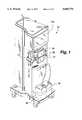
- FIG. 1is a perspective view of a dialysis machine which incorporates the present invention.
- FIG. 2is a generalized view illustrating a dialyzer, an extracorporeal flow path for blood from a patient through the dialyzer, and a hydraulics flow path for dialysate through the dialyzer, as are present during treatment of a patient with the dialysis machine shown in FIG. 1.
- FIG. 3is a block diagram of control and safety systems of the dialysis machine shown in FIGS. 1 and 2, illustrating the graphical OMI and the method of information entry and presentation according to the present invention.
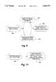
- FIG. 6is a flow chart of steps taken to select among the setup parameters shown in FIG. 5 and to present the selected parameters in a customized setup parameter display screen shown in FIG. 7.
- FIG. 9is an illustration of a display screen of monitoring parameters which may be selected for presentation in a customized monitoring parameter display screen according to the present invention.
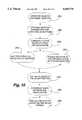
- FIG. 10is a flow chart of steps taken to select among the monitoring parameters shown in FIG. 9 and to present the selected parameters in a customized monitoring parameter display screen.
- FIG. 12is an illustration of a display screen of alarm limits parameters which may be selected for presentation in a customized alarm limits parameter display screen according to the present invention.
- FIG. 16is a flow chart of steps taken to select among the default parameters shown in FIG. 15 and to modify or establish values for the selected default parameters.
- FIG. 18is a flow chart of steps taken to select the wake-up parameters shown in FIG. 17 and to modify or establish values for the wake-up programming parameters.
- the dialysis machine 30includes the devices generally shown in FIG. 2, and those devices establish an extracorporeal flow path and a hydraulics flow path.
- the extracorporeal flow pathconducts blood from a patient 32 to a dialyzer 34, and then returns the blood from the dialyzer 34 to the patient 32.
- the hydraulics flow pathconducts dialysate from a supply 36 to the dialyzer 34, and then returns the used dialysate to a waste drain 38.
- the blood in the dialyzer 34is confined to a blood chamber 40, and the dialysate in the dialyzer 34 is confined to a dialysate chamber 42.
- the blood chamber 40 and the dialysate chamber 42are separated by a microporous or other type of dialysis membrane or medium 44.
- the waste products contained in the blood within the blood chamber 40are transferred through the medium 44 by osmosis, ionic transfer or flow transfer to the dialysate in the dialysate chamber 42. Desirable components of the dialysate in the dialysate chamber 42 may also be transferred to the blood in the blood chamber 40 by the same mechanisms. In this manner, the waste products are removed from the patient's blood, and the cleansed blood is returned to the patient 32.
- the used dialysate flowing from the dialysate chamber 42discharges the waste products into the drain 38, which may be a public sewer.
- the elements of the extracorporeal flow pathinclude at least one blood pump 46 which controls the flow of blood from the patient 32.
- An arterial line or tubing 48extends through an arterial clamp 50 to a blood handling cartridge 52.
- the blood handling cartridge 52is normally retained behind a door 54 of the machine 30 when used.
- the blood handling cartridge 52is not shown in FIG. 1.
- the blood pump 46also is located behind the door 54 and adjacent to the cartridge 52.
- the blood pump 46is typically a peristaltic pump in dialysis machines.
- the blood pump 46draws blood from the arterial chamber 56 through a pump tubing 58 which is squeezed or pinched by a rotating rotor 60 against a stationary raceway 62, in the typical manner of peristaltic pumps.
- the blood within the pump tubing 58 which is rotationally in front of the rotor 60is propelled through the pump tubing 58 and into a manifold 64 of the cartridge 52.
- a tubing 66conducts the blood from the manifold 64 of the cartridge 52 into a blood inlet of the dialyzer 34.
- the cleansed blood flowing from an outlet of the dialyzer 34is transferred through a tubing 67 back to a venous chamber 68 of the cartridge 52. Blood from the venous chamber 68 is removed from the cartridge 52 through a venous tubing or line 70.
- a venous blood pump similar to the arterial blood pump 46may be located in the venous line to assist in forcing the blood back into the patient 32 or to regulate the flow of blood through the extracorporeal flow path. If employed, the venous blood pump is positioned behind a second door 72 of the dialyzer machine 30 shown in FIG. 1.
- the elements of the hydraulics flow pathinclude a number of different valves (most of which are not shown) and a dialysate pump 84 which draws dialysate from the supply 36.
- the supply 36is typically a container, an internal quantity of dialysate which the dialysis machine 30 has prepared from appropriate chemicals and a supply of purified water or an external supply delivered to the machine.
- the dialysate pump 84draws the dialysate from the supply 36 and delivers it through a dialysate supply tubing or line 86 to an inlet of the dialysate chamber 42 of the dialyzer 34.
- the dialysateflows past the medium 44 where it absorbs the waste products from the blood in the blood chamber 40. Any beneficial components within the dialysate which are desired to be transferred to the blood pass through the medium 44 and into the blood in the blood chamber 40.
- the dialysatePrior to entering the dialyzer 34, the dialysate is heated in a heater 88 to the normal human body temperature.
- the temperature of the dialysate entering the dialyzer 34should be at body temperature to avoid removing heat from the patient. Excessively warm dialysate will harm blood cells. Excessively cool dialysate will chill the patient.
- Temperature sensors(not shown) are located in the dialysate supply line 86 to monitor the temperature of the dialysate.
- Conductivity sensorsare also present in the dialysate supply line 86 to measure the conductivity of the dialysate.
- the desired level of ionic transfer between the blood and the dialysateis achieved by predetermined conductivity characteristics of the dialysate.
- the used dialysate containing the waste productsis removed from the dialysate chamber 42 through a dialysate waste tubing or line 90 by operation of a drain pump 94.
- the dialysate containing the waste productsis delivered by the drain pump 94 to the waste drain 38.
- the waste drain 38may be a separate container which accumulates the used dialysate and accumulated waste products, or it may simply be a public sewer.
- bypass valves 96 and 98are positioned at the inlet and the outlet of the dialysate chamber 42, respectively.
- the bypass valves 96 and 98are connected by a bypass line 100.
- Normally the bypass valve 96directs the inflow of dialysate into the dialysate chamber 42, and normally the bypass valve 98 directs the outflow of dialysate into the dialysate waste line 90. If a safety condition is detected, the bypass valves 96 and 98 are operated to their alternative, abnormal states, thereby directing the flow of dialysate through the bypass line 100, and bypassing the flow of dialysate around the dialyzer 34.
- the elements of the extracorporeal flow pathwhich have generally been described above, are shown and referenced generally at 110 in FIG. 3.
- the extracorporeal flow path elements 110are controlled by an extracorporeal microcontroller 112 or other similar processing device, as shown in the systems diagram of FIG. 3.
- the extracorporeal microcontroller 112executes a program recorded in a memory 114 to control the extracorporeal flow path elements 110.
- An operator/machine interface (OMI) and protective microcontroller 122is also connected to the extracorporeal flow path elements 110 and the hydraulic flow path elements 116.
- the OMI and protective microcontroller 122monitors the operating conditions in the extracorporeal and hydraulics flow paths, and upon detecting a potentially risky condition for the patient, assumes control over the extracorporeal and hydraulics flow path elements 110 and 116 to place the machine into a safe patient state.
- the protective microcontroller 122executes a program recorded in its memory 124 to monitor the operating conditions of the dialyzer machine 30 and the conditions of the patient 32 during dialysis treatment, to determine a potentially hazardous condition, and to place the dialyzer machine in a safe patient state upon the detection of a hazardous condition.
- the three microcontrollers 112, 118 and 122communicate with one another to exchange information and confirm proper functionality, among other things, by use of a bus or network 126.
- the extracorporeal microcontroller 112 and the hydraulic microcontroller 118are generally responsible for the system management control functions of the dialysis machine.
- the protective microcontroller 122is responsible for the safety functions of the dialysis machine.
- the present inventionachieves a more convenient and natural approach to entering, selecting and presenting information into a dialysis machine, while simultaneously offering a substantially greater and more flexible opportunity to customize the dialysis machine for optimal patient treatment and optimal convenience of the operator in monitoring the machine and the patient during treatment.
- the touch screen 130is a thin transparent sheet assembly which physically overlays a front viewing surface of the CRT 132.
- the overlaying relationshipis generally illustrated in FIG. 3.
- the images displayed on the viewing surface of the CRT 132define locations which the operator may select by applying finger pressure to the touch screen 130 at the location of the images.
- the touch screen 130generates signals which describe the X-Y coordinates of the position where the finger pressure is applied. Those signals are supplied to a conventional touch screen converter 136 which converts the X-Y signals from the touch screen 130 into corresponding signals which are supplied to the protective microcontroller 122.
- the programmed functionality of the protective microcontroller 122correlates the signals from the touch screen converter 136 with the location of the images displayed on the viewing surface of the CRT 132.
- the correlationis possible because signals are supplied by the protective microcontroller 122 to a video driver 138 to control the position and details of the images displayed on the viewing screen of the CRT 132.
- the microcontroller 122is able to recognize those selections made by the operator touching the touch screen 130. This functionality is typical and well known for touch screen input and output (I/O) devices.
- an audio alarm 140 and a visual alarm 142are part of the dialysis machine 30.
- the audio and visual alarms 140 and 142are controlled by a driver 144.
- the driver 144responds to control signals supplied by the protective microcontroller 122.
- the protective microcontroller 122delivers signals to the driver 144 to create a visual alarm or signal or an audio alarm or signal when necessary.
- FIG. 4An example of a visual display created by the protective microcontroller 122 and the video driver 138 is shown in FIG. 4.
- the visual display shown in FIG. 4is a typical presentation selected by the operator when monitoring the patient and the machine during treatment.
- the displayappears on the viewing screen of the CRT 132, and it will therefore be referred to as a display screen 150.
- the display screen 150is divided into different areas which present information concerning the functions and status of the dialysis machine.
- a relatively large main window area 152shows a number of parameters which are being monitored during the treatment, in this example.
- a title bar 154indicates that the parameters being monitored are shown in the main window 152.
- the right-hand border or other designated area of the display screen 150(as shown) is occupied by images which allow the operator to select other display and functional features of the machine.
- Finger pressure at a screen image 156allows the operator to index among various display options, and, for example, select the monitoring parameters, as is shown at 154 and 156. Pressing the touch screen above a last screen image 158 allows the operator to toggle between the present display screen 150 and the display screen which was previously displayed.
- Finger pressure above a treatment setup image 160allows the operator to select and view a list of dialysis options that are expected with each treatment, for example, prime, start therapy, stop therapy, and the like.
- a quick OPS image 162allows the operator to select and view in a relatively convenient manner, those optional parameters that are not necessarily accessed during the treatment.
- the on and off operation of the blood pump 46(FIG. 2) is controlled by finger pressure above blood pump icon or image 164.
- the blood pumpis turned on and off with each finger contact.
- the rate of blood pump operationmay be adjusted incrementally upward or incrementally downward by finger pressure on an up arrow image 166 or a down arrow image 168, respectively. Continual finger pressure on either of the arrow images 166 or 168 causes repeated incrementation.
- the blood pumping rateis displayed in the location where the word "off" appears in the blood pump image 164.
- the bottom border or other designated area of the display screen 150also includes a number of images or icons which represent control and monitoring conditions associated with the patient and the dialysis machine.
- the image at 170 which states "resume”is selected to resume operation of the blood pump operation if the blood pump has stopped.
- the image at 172which states "UF” accompanied by a downward pointing arrow is selected when it is desired to reduce the amount of ultrafiltration which may be occurring during a treatment.
- Ultrafiltrationis a well-known aspect of some types of dialysis treatments which involves the direct introduction of an ultrafiltration solution into the blood.
- the ultrafiltratemay be introduced into the extracorporeal flow path prior to the blood reaching the dialyzer 34 (FIG. 2) or after the blood has passed through the dialyzer.
- the dialyzer 34FIG. 2
- no functionalitywill be achieved by finger pressure above the ultrafiltration image at 172.
- the image displayed at 174is an icon representative of the function of bypassing the dialysate flow around the dialyzer 34 (FIG. 2).
- the dialyzer 34is bypassed when the valves 96 and 98 divert the dialysis flow through the bypass line 100 (FIG. 2).
- Finger pressure above the bypassed dialyzer image 174results in the immediate ability for the operator to achieve the safety condition of bypassing the dialyzer.
- the image or icon of a heart at 176allows the operator to instruct the dialysis machine to take a blood pressure reading from the patient.
- the patientis connected to a typical blood pressure sensing cuff and the machine is equipped to automatically read and display the blood pressure reading obtained.
- the basic template for the presentation of information at the display screen 150is replicated in all of the display screens presented to the operator during setup, monitoring and other general use of the dialysis machine.
- the substantially consistent template for all of the display screens and the similar organization of the display screensallows a more convenient, time-conserving, reliable and safety-promoting approach to setting up, monitoring and using the dialysis machine.
- One of the important improvements of the present inventionis the customization of the information and the programming of the dialysis machine through use of the graphical information presented on the display screens.
- the screens and the operator interaction with those screensare available to obtain substantially complete and convenient access to those parameters which control the operation of the dialysis machine, as well as equally complete and convenient access to those parameters which are desired to be monitored during the treatment.
- the access to the parametersis accomplished according to the needs and preferences of the operator, rather than as part of a fixed functionality established by the dialysis machine manufacture.
- the dialysis machineis more conveniently and efficiently used according to the preference of the operator or the dialysis clinic, according to the particularized treatment prescribed for the patient, and possibly with additional comfort to the patient.
- OMIoperator machine interface
- FIGS. 5-20The features of the improved OMI and the methodology of the present invention are described in FIGS. 5-20.
- the majority of the steps involved in practicing this inventionare accomplished by the OMI/protective microcontroller 122 which executes the software program recorded in the memory 124 (FIG. 3). Some of the other steps are accomplished manually by the operator.
- FIGS. 6, 8, 10, 11, 13, 14, 16, 18, and 20are separately identified by reference numbers for convenience of description.
- the upper level of customizationrepresents the selection of parameters to be displayed or monitored, as well as the organization and presentation of a display screen to best represent those parameters.
- the second level of customizationinvolves establishing and changing the values or quantities of those parameters.
- the second level of customizationis principally described in the concurrently filed application for an Information Entry Validation System and Method for a Dialysis Machine, Ser. No. 08/484,015.
- the important graphical customization feature of the present invention of selecting the parameters to be presented for programming and monitoring the machineis initiated by the operator touching the screen button 156, as shown in FIGS. 5 and 6. Repeated touches to the screen button 156 present different screen options until the Customize option is presented at 178.
- the Customize optionis highlighted at the bottom portion of the screen button 156, as is shown.
- the bottom border area of icons and images at 170, 172, 174 and 176 shown in FIG. 4is replaced by the features which may be customized. Those features shown in FIG.
- Defaults button 186all of the default parameters available from the machine represented by a Defaults button 186, an automatic operation described more particularly in the concurrently filed application for a Technique for Automatically Preparing Dialysis Machine at a Predetermined Date and Time, Ser. No. 08/484,013, in which the dialysis machine automatically initiates a clean and disinfection operation prior to dialysis treatments, represented by a Wake-Up button 188, and an operation in which the location of finger pressure on the touch screen 130 (FIG. 3) is calibrated to the images presented, represented by a Touch Screen button 190.
- setup button 180has been touched and as a result is highlighted as shown in FIG. 5.
- the selection of the setup button 180results in the presentation of all setup parameters available in the main window 152. All of the parameters shown in the main window 152 are available for selection by the operator.
- setup parametersare those which control the operation of the dialysis machine during treatment. The quantities associated with each of these parameters will generally need to be adjusted by the operator prior to each treatment, or must be confirmed by the operator prior to treatment.
- the list of parameters which are presented as shown in FIG. 5 and at step 192 in FIG. 6is conceivably any variable of operation of the dialysis machine.
- the list of parameters shown in FIG. 5is presently considered to be the most useful group.
- Those parametersinclude the Patient ID, which represents a number or other identification assigned to a patient.
- the patient identification numberis frequently used by dialysis clinics to record the specific treatment information and results to specific patients.
- the Target Loss parameterdescribes the weight or volume of waste which is desired to the removed from the patient during the treatment.
- the Treatment Timeis the time allotted for the treatment.
- the Therapy Typerefers to the type of therapy which may be performed. Examples of dialysis therapy treatments are hemodialysis, isolated ultrafiltration and hemodiafiltration. Other types are also known.
- the Needle Configuration parameterrefers to whether a single needle or a double needle dialysis treatment is performed.
- a double needle treatmentis illustrated in FIG. 2.
- a single needle treatmentinvolves withdrawing blood from the patient and returning blood to the patient through a single needle, with the withdrawal and return flows occurring in a forward and backward flow manner.
- the Buffer Type parameterrelates to the type of buffer solution used in the dialysate. Typical buffers are acetate and bicarbonate.
- the Bicarbonate Dilutiondescribes the dilution ratio of bicarbonate to acid used in the dialysate.
- the Final K+ parameterrelates to the concentration of potassium in the dialysate.
- the Blood Tubing Sizerelates to the size of the pump tubing 58 (FIG. 2) used in the blood handling cartridge. The size of the pump tubing is important because it determines the volume of blood which is transferred by the blood pump rotor with each rotation.
- the SN Pressure Control parameterrelates to the pressure limits for the differential pressure transitions that are employed to push blood into the patient and withdraw blood out of the patient with a single needle dialysis treatment.
- the Dialysate Temperature parameterrelates to the temperature of the dialysate supplied to the dialyzer.
- the dialysate temperatureis established by the heater 88 (FIG. 2).
- the Dialysate Flow parameterdescribes the flow rate of dialysate through the dialyzer.
- the Fluid Removal Profile parameterdescribes the rate of fluid removed from the patient relative to time. The profile may be a constant rate during the treatment time, a combination of different rates, variable rates over the treatment time, or one or more step function increases over the treatment time.
- the Sodium Profiledescribes the sodium content of the dialysate over time. The variability of that rate may include all of the functions described with respect to the fluid removal profile.
- the Bicarbonate Profilealso describes a function of the bicarbonate in the dialysate relative to the treatment time.
- the Heparin Rate parameterdescribes the rate of delivery of heparin from the syringe 78 (FIG. 2) during the treatment time.
- the heparin ratemay be constant or it may also be a variable function of time and have its own profile.
- the Heparin Stop Time parameterdescribes the time in the treatment where the delivery of heparin is terminated. Toward the end of a dialysate treatment the heparin delivery is typically terminated, because the patient's blood is reasonably well anticoagulated by that time.
- the Heparin Syringe Type parameteris intended to describe the size of the syringe used.
- the Infusate Profile parameterdescribes the rate of delivery of infusate to the bloodstream in a function which varies with the treatment time. Again, the infusate profile may take a variety of rates and functions relative to time.
- the Blood to Processis a parameter that describes the quantity of blood processed. This parameter may be set or used as the primary determinant of the length of the treatment.
- the Target Blood Flow parameterdescribes the desired blood flow rate through the extracorporeal flow path.
- the Blood Flow Rampdescribes the variability in the blood flow rate relative to the time of the treatment. This ramp effect is similar to a profile where the rates may change as a function of time.
- the operatorAfter the parameters shown in FIG. 5 have been selected by touching the setup button 180, which becomes highlighted after being touched, the operator thereafter selects those parameters which the operator wishes to establish for each treatment, or for the individual treatment to be performed next. Selection of the parameters is obtained by touching the button or area of the display screen where the variable is displayed. Those currently active parameters are highlighted, as shown at 194 in FIG. 6. The highlighted parameters which the operator desires to select need not be touched again, because those parameters have been previously selected.
- the OMIwaits for the operator to begin selecting buttons by touching the images, as shown at 196.
- Those parameters which have previously been selectedmay be de-selected by touching the highlighted parameter.
- the touchcauses a toggling effect on both the highlighted and the non-highlighted buttons.
- Parameters not previously selectedare selected by touching the non-highlighted button, and parameters previously selected which are desired to be de-selected are touched in their highlighted buttons.
- the resulting toggling effectachieves the selection or de- selection, as shown at 198.
- those previously selected parameters which are to remain selectedare not touched since the previous selection will continue until toggled into the opposite state of selection.
- an Accept button 200(FIG. 5) is touched at 202 (FIG. 6).
- the touch to the accept button 200is interpreted as the final selection by the operator, and thereafter the highlighted parameters are determined by the OMI at 204 (FIG. 6).
- the display screenis rebuilt or restructured to present only the selected parameters as shown at 206 in FIG. 6 and in the display screen 150 in FIG. 7.
- step 192starts the sequence of customizing the setup parameters in the manner just described.
- the keypad display 214includes a number of different areas. These areas define numeric buttons 216, a selected parameter display area 218 which presents a title corresponding to the parameter selected at 212, a decimal point button 220, an escape button 222, a clear button 224, and an enter button 226.
- an up arrow 228 and a down arrow 230are located adjacent to the display area 218 for the purpose of incrementing the value of the parameter shown in the display area 218, either upwardly or downwardly.
- the operatorchanges the value of the highlighted parameter using the keypad as shown at 230 in FIG. 8.
- the operatorcontinues selecting the parameters and changing the values of those parameters as shown at 210 and 230 in FIG. 8 until all of the values have been changed to the satisfaction of the operator.
- the operatorverifies all of the values established for all of the selected parameters as shown at 232 in FIG. 8. The operator verifies the values by touching the enter button 226 (FIG. 7).
- the improved graphical functionality of the OMI and the method of selecting and entering information for the setup parameters described in conjunction with FIGS. 4-7represents the two levels of customization available from the present invention.
- the first level of customizationallowed the operator to conveniently access and select those operational parameters which were desired to control and optimize the treatment.
- the final setup parameter display screenpresents those selected parameters in a clear and easy to comprehend manner.
- the second level of customizationallows the values of each parameter to be adjusted, again in a convenient and easy to comprehend manner. As a result, the optimal conditions for both the operator and the patient are easily obtained.
- FIGS. 9 and 10Various monitoring parameters can also be selected for monitoring during treatment, as shown in FIGS. 9 and 10.
- the monitor button 182is touched as shown in FIG. 9 and it becomes highlighted. Touching the monitor button 182 constitutes a selection of the customizing function for the monitored parameters as shown at step 234 in FIG. 10. All of the optional monitor parameters are then presented in the main display window 152 (FIG. 9) as a result of the step 236 (FIG. 10). The currently effective ones of the monitoring parameters are highlighted in the display as a result of the step 238 (FIG. 10).
- Those monitoring parameters which have previously been selectedare highlighted. Those previously highlighted parameters which the operator no longer wishes to monitor are de-selected by touching the highlighted button, thereby toggling the highlighted parameter into a de-selected state. Similarly, those monitoring parameters which were not previously selected are selected by touching the non-highlighted button. Touching the highlighted and non-highlighted buttons in this manner constitute the selection of the buttons shown at step 240 (FIG. 10), and the toggling of the selected and de-selected monitoring parameters is shown at step 242.
- the THP monitoring parameterrefers to the "trans-membrane pressure.”
- the TMPis the pressure differential across the dialyzer medium 44 between the blood chamber 40 and the dialysate chamber 42 (FIG. 2).
- the TMPis monitored to evaluate the effectiveness of the medium and to identify a condition under which the medium may become obstructed to the flow through it.
- the Stroke Volume monitoring parameterrelates to the volume of ultrafiltrate delivered by an ultrafiltration pump during ultrafiltration dialysis treatments, or to the volume of sterilant delivered by a sterilant pump during disinfection of the hydraulics flow path.
- the Average Blood Flow monitoring parameterdescribes the average blood flow rate through the dialysis machine during the course of the treatment. Of course other monitoring parameters could be displayed if those parameters are useful to the operator and available in the dialysate machine.
- the operatoraccepts those monitoring values by touching the accept button 200 (FIG. 9) at the step 244 (FIG. 10).
- Activation of the accept button at step 244causes the OMI to determine which of the monitoring parameters has been selected as shown at step 246. Thereafter those selected monitoring parameters are rebuilt and displayed in the main window area 152 of the display screen 150 (FIG. 9) by the step 248 (FIG. 10).
- the operatormay touch the cancel button 207, causing the program flow to revert back to the step at 236.
- the entire program flow for selecting monitoring parameters to be presentedcan thereafter be started again.
- monitoring the parametersbegins with the operator selecting the monitor screen shown at step 250.
- the previously selected monitoring parametersare thereafter displayed as shown at step 252. Because monitoring is occurring, there are no values to set or modify. The values of the monitoring parameters are simply displayed. Therefore the second level of customization available for setting or modifying the selected parameters is not available for the monitoring parameters.
- Various alarm limits parameterscan be selected for a customized screen display by touching the alarm limits button 184 as shown in FIG. 12 and at the step 254 in FIG. 13.
- the available alarm limits parametersare displayed at step 256 (FIG. 13) in the main display window 152 of the screen display 150 (FIG. 12).
- the currently selected alarm limits parametersare highlighted and those de-selected alarm limits parameters are not highlighted as shown at step 258.
- the operatorselects those non-highlighted alarm limits parameters by touching the alarm limits parameter buttons desired.
- the operatoralso de-selected those active alarm limits parameters by touching the highlighted alarm limits parameter buttons. Touching the highlighted and non-highlighted parameter buttons changes the states of the selected parameter from active to not-active and from not-active to active, as the case may be. Touching the alarm limits buttons selects them as shown at step 260 (FIG. 13) and also toggles the state of the selected alarm limits parameter as shown at step 262.
- the types of alarm limits available to be monitoredinclude all of those typical and relevant ones used in dialysis.
- the main alarm limits shownare the Systolic Blood Pressure, the Diastolic Blood Pressure and the Mean Arterial Blood Pressure of the patient; the Arterial Pressure, the Venous Pressure and the System Pressure within the extracorporeal flow path; the Conductivity of the dialysate; the Bicarbonate Conductivity of the dialysate; the pH of the dialysate; the patient's Pulse rate; and the TMP or trans medium pressure in the dialyzer.
- Other alarm limits parameterscould include the temperature of the dialysate.
- the accept button 200 (FIG. 12) of the display screenis touched as shown at step 264 (FIG. 13). Thereafter the OMI determines which of the available alarm limits parameters have been selected at step 266, and the customized alarm limits display screen is presented at step 268.
- the second level of establishing or modifying the alarm limits parametersis available to the operator as shown in FIG. 14. Initiation of the procedure for modifying or establishing values for the alarm limits parameters begins at step 270 where the operator has selected the alarm limits screen. The values associated with the selected alarm limits parameters will be displayed in the alarm limits parameters buttons, in a manner similar to that shown for the setup parameters in FIG. 7. In addition a keypad will also be presented on the display screen. A touch to the alarm limits parameter of interest highlights that alarm limit parameter and makes its value available to be established or modified, as shown at step 272. Thereafter the high and low limits for the selected parameter are displayed graphically as shown at step 274.
- the operatorselects one of the high or low limits at step 276 and modifies that value at step 278.
- the steps 272, 274, 276 and 278are repeated until all of the alarm limits and the values associated with each alarm limit is established or modified to the satisfaction of the operator.
- the OMI/protective microcontroller 122(FIG. 3) checks the values which the operator enters at step 278 against established acceptable limits before the operator is allowed to accept those entered values. An evaluation of the entered value relative to an acceptable range of values assures that the operator can not program the machine in an unsafe manner.
- the dialysis machineis adjusted for optimal efficiency in use by the operator and safety for the patient.
- the customized display screens for the setup parameters, the monitoring parameters and the alarm limits parameterswill normally accomplish all of the functionality required by an operator, all of the parameters associated with the dialysis machine are also available to be selected and the values associated with those parameters modified.
- the screen display presentation for all of the parameters, including those which are otherwise displayed on the customized display screens,are conveniently accessible through selection of the defaults button 186 shown in the screen display 150 in FIG. 15.
- the defaults button 186When the operator touches the defaults button 186, as shown by step 280 in FIG. 16, the entire list of default parameters is presented in the main window 152 (FIG. 15) and at step 282 (FIG. 16).
- a scroll-up arrow 284 and a scroll-down arrow 286Touching the arrows 284 and 286 causes a highlighted bar to move up and down the list of default parameters. Once the highlighted bar has been position over the selected default parameter, the operator touches a select button 288 to select the desired default parameter. Identifying the desired default parameter by use of the highlighted box and the scroll-up and scroll-down arrows is shown at step 290 (FIG. 16), and selecting that default parameter is shown at step 292. After the desired default parameter has been selected, the value of that parameter is available to be changed by use of the popup keypad 214 shown in FIG. 7. Changing the default parameter value is shown at step 234 (FIG. 16). If the dialysis machine is connected to a patient the changed value of the selected default parameter immediately takes effect. However if the machine is not connected to a patient as shown at step 296, the operator may store the changed value of the parameter to memory.
- the defaults parameter display screenallows the operator to quickly and conveniently obtain access to every parameter available in the machine.
- any parameter which may not have been included in any of the options for customized display screensis available to be modified.
- Total flexibility in the use and programming of the dialysis machineis therefore available to the operator in a convenient and easy to use manner provided by the graphical display and programming capabilities of the defaults functionality.
- aspects of the present inventionallow the machine operator to customize a schedule for an automatic cleaning and disinfecting function of the machine.
- This automatic functionalityis discussed in detail in the concurrently filed application for a Technique for Automatically Preparing Dialysis Machine at a Predetermined Date and Time, Ser. No. 08/484,013.
- this automatic functionalityallows the hydraulics flow path other than the dialyzer to be completely cleaned and disinfected as a result of the machine automatically conducting the appropriate cleaning and disinfecting solutions through the machine, prior to the time when the machine will be used for dialysis treatments.
- the advantage of this automatic featureis that the time of the operator need not be devoted to the cleaning and disinfecting functions, but can be focused on the protective activity of dialysis treatments.
- the ability to program the dialysis machine to start this automatic cleaning and disinfecting functionality at a particular timeis one of the features of this invention.
- This programming capabilityis referred to as "wake-up" customization.
- Programming the wake-up timesis achieved by touching the wake-up button 188 as shown in FIG. 17 to thereby accomplish the step 238 shown in FIG. 18.
- the main window 152 of the display screen 150presents the operator with the buttons used to program the wake-up features, as shown at step 300 (FIG. 18).
- buttons presented to the operatorinclude a button 302 identifying each day of the week when the operator desires to use the wake-up feature of the dialysis machine. Buttons 304 adjacent to the days of the week buttons 302 allow the operator to select the time of day to start the wake-up functionality.
- the wake-up functionalityitself is selectable by the operator at buttons 306 and 308.
- a rinse button 306is used to program a rinsing function.
- An idle button 308is used to program an idle function which generally describes the state of the dialysis machine after the initial start and execution of all of the self-tests and other similar functions.
- Another wake-up button 310is located in the main window area 152 to present the operator with the option of enabling or disabling the entire wake-up function.
- buttons presented in the display screen 150 shown in FIG. 17,the operator accomplishes the steps shown in FIG. 18.
- the active featuresare shown by highlighted buttons, and the times and days when those functions become active are also highlighted as shown at step 312.
- the operatorfirst makes the selection to enable or disable the wake-up function at step 314 by touching the wake-of button 310 (FIG. 18) to toggle between an enabled condition or a disabled condition.
- the operatorchooses the desired wake-up function at step 316 by touching one of the buttons 306 or 308 (FIG. 17).
- the operatorchooses the days of the week when the wake-up function is desired by touching those days of the week buttons 302 (FIG. 17) to highlight the days desired, as shown at step 318 (FIG. 18).
- the popup keypadis presented to the operator. Using the keypad the operator enters the starting time as shown at step 320 (FIG. 18).
- All of the days of the weekare programmed with the desired wake-up function and the desired time by repeating the steps 314, 316, 318 and 320.
- the accept button 200(FIG. 17) is touched to accept this programming at step 322 (FIG. 18).
- the OMI/protective microcontroller 122determines which of the buttons have been highlighted at step 324 and establishes the new wake-up schedule at step 326 based on these selections.
- One of the important requirements of the graphical touch screen programming employed in the present inventionis an ability to accurately correlate the touch points on the screen to the desired selection presented to the operator. Correlation between the touch point and the displayed information is accomplished by the operator touching the touch screen button 190, shown in FIG. 19. The step of touching the touch screen button 190 is shown at 328 in FIG. 20.
- a first cross-hair symbol 322(FIG. 19) is displayed in the main window 152 at step 324 (FIG. 20).
- the operatortouches the first cross-hair symbol at step 326.
- a second cross-hair symbol 328(FIG. 19) is displayed at step 330 (FIG. 20). Again the operator touches the second cross hair symbol at step 332 (FIG. 20).
- a third cross-hair symbol 334(FIG. 19) is presented to the operator at step 336 (FIG. 20), and again the operator touches that symbol at step 338.
- the accept button 200(FIG. 19) is presented to the operator at step 340 (FIG. 20).
- the cancel button 207(FIG. 19) can be touched at any time during the procedure shown in FIG. 20, as represented by step 344.
- the effect of touching the cancel button at step 344is to cause all of the previous information obtained from the touch screen procedure shown in FIG. 20 to be disregarded as shown at step 346.
- the graphical OMI of the present inventionoffers significant convenience and flexibility in allowing the operator to access most of the important parameters associated with safely operating a dialysis machine. Accessing these parameters allows the dialysis machine to be customized for optimal patient treatment and optimal operator efficiency during treatments. Optimal treatment is particularly important because of the increased emphasis on varying some of the operating and monitoring parameters which traditionally have not been varied or available to be varied, particularly by the operator of the machine. As a result, the present invention represents a significant advancement in the flexibility and adaptability of dialysis machines for optimal patient treatment and clinical use.
Landscapes
- Health & Medical Sciences (AREA)
- Engineering & Computer Science (AREA)
- Heart & Thoracic Surgery (AREA)
- Vascular Medicine (AREA)
- General Health & Medical Sciences (AREA)
- Public Health (AREA)
- Animal Behavior & Ethology (AREA)
- Veterinary Medicine (AREA)
- Anesthesiology (AREA)
- Biomedical Technology (AREA)
- Hematology (AREA)
- Life Sciences & Earth Sciences (AREA)
- Cardiology (AREA)
- Software Systems (AREA)
- Urology & Nephrology (AREA)
- Theoretical Computer Science (AREA)
- Emergency Medicine (AREA)
- Chemical Kinetics & Catalysis (AREA)
- Chemical & Material Sciences (AREA)
- Human Computer Interaction (AREA)
- Water Supply & Treatment (AREA)
- Physics & Mathematics (AREA)
- General Engineering & Computer Science (AREA)
- General Physics & Mathematics (AREA)
- External Artificial Organs (AREA)
Abstract
Description
Claims (38)
Priority Applications (1)
| Application Number | Priority Date | Filing Date | Title |
|---|---|---|---|
| US08/486,944US5609770A (en) | 1995-06-07 | 1995-06-07 | Graphical operator machine interface and method for information entry and selection in a dialysis machine |
Applications Claiming Priority (1)
| Application Number | Priority Date | Filing Date | Title |
|---|---|---|---|
| US08/486,944US5609770A (en) | 1995-06-07 | 1995-06-07 | Graphical operator machine interface and method for information entry and selection in a dialysis machine |
Publications (1)
| Publication Number | Publication Date |
|---|---|
| US5609770Atrue US5609770A (en) | 1997-03-11 |
Family
ID=23933755
Family Applications (1)
| Application Number | Title | Priority Date | Filing Date |
|---|---|---|---|
| US08/486,944Expired - LifetimeUS5609770A (en) | 1995-06-07 | 1995-06-07 | Graphical operator machine interface and method for information entry and selection in a dialysis machine |
Country Status (1)
| Country | Link |
|---|---|
| US (1) | US5609770A (en) |
Cited By (120)
| Publication number | Priority date | Publication date | Assignee | Title |
|---|---|---|---|---|
| US5752931A (en)* | 1996-09-30 | 1998-05-19 | Minnesota Mining And Manufacturing Company | Perfusion system with perfusion circuit display |
| US5788851A (en)* | 1995-02-13 | 1998-08-04 | Aksys, Ltd. | User interface and method for control of medical instruments, such as dialysis machines |
| US5813972A (en)* | 1996-09-30 | 1998-09-29 | Minnesota Mining And Manufacturing Company | Medical perfusion system with data communications network |
| US5858239A (en)* | 1997-02-14 | 1999-01-12 | Aksys, Ltd. | Methods and apparatus for adjustment of blood drip chamber of dialysis machines using touchscreen interface |
| EP0904788A1 (en)* | 1997-09-26 | 1999-03-31 | Fresenius Medical Care Deutschland GmbH | Apparatus and method of operating medico-technical devices |
| US5938938A (en)* | 1995-07-04 | 1999-08-17 | Hospal Ag | Automatic dialysis method and apparatus |
| US6164920A (en)* | 1996-09-30 | 2000-12-26 | Minnesota Mining And Manufacturing Company | Perfusion system with control network |
| USD462362S1 (en) | 2001-02-20 | 2002-09-03 | Hospal International Marketing Management | Icon for a display panel on a medical apparatus |
| USD462698S1 (en) | 2001-02-20 | 2002-09-10 | Hospal International Marketing Management | Icon for a display panel on a medical apparatus |
| USD462696S1 (en) | 2001-02-20 | 2002-09-10 | Hospal International Marketing Management | Icon for a display panel on a medical apparatus |
| USD464060S1 (en) | 2001-02-20 | 2002-10-08 | Gambro Inc. | Icon for a display panel on a medical apparatus |
| US20030083901A1 (en)* | 2001-06-22 | 2003-05-01 | Bosch Juan P. | Process for providing dialysis and other treatments |
| US20030117296A1 (en)* | 2000-07-05 | 2003-06-26 | Seely Andrew J.E. | Method and apparatus for multiple patient parameter variability analysis and display |
| US6587728B2 (en) | 2001-03-30 | 2003-07-01 | Neurocontrol Corporation | Systems and methods for performing prosthetic or therapeutic neuromuscular stimulation using an external, battery powered controller with power conservation features |
| US6625494B2 (en) | 2001-03-30 | 2003-09-23 | Neurocontrol Corporation | Systems and methods for performing prosthetic or therapeutic neuromuscular stimulation using a universal external controller providing different selectable neuromuscular stimulation functions |
| US20030212314A1 (en)* | 2002-04-15 | 2003-11-13 | Nikkiso Co. Ltd. | Medical device |
| US20030218623A1 (en)* | 2002-05-24 | 2003-11-27 | Andrea Krensky | Graphical user interface for automated dialysis system |
| US6678563B2 (en) | 2001-03-30 | 2004-01-13 | Neurocontrol Corporation | Systems and methods for performing prosthetic or therapeutic neuromuscular stimulation using a universal external controller having a graphical user interface |
| US6701189B2 (en) | 2001-03-30 | 2004-03-02 | Neurocontrol Corporation | Systems and methods for performing prosthetic or therapeutic neuromuscular stimulation using a universal external controller accommodating different control inputs and/or different control outputs |
| US20040111294A1 (en)* | 2002-12-09 | 2004-06-10 | Mcnally Larry | System and a method for providing integrated access management for peritoneal dialysis and hemodialysis |
| US20040111293A1 (en)* | 2002-12-09 | 2004-06-10 | Catherine Firanek | System and a method for tracking patients undergoing treatment and/or therapy for renal disease |
| US6775577B2 (en) | 2001-07-18 | 2004-08-10 | Fresenius Usa, Inc. | Method and system for controlling a medical device |
| US6799135B2 (en)* | 2001-01-29 | 2004-09-28 | Sii Nanotechnology Inc. | User friendly analysis system |
| US20040236387A1 (en)* | 1998-06-03 | 2004-11-25 | Neurocontrol Corporation | Treatment of shoulder dysfunction using a percutaneous intramuscular stimulation system |
| WO2004103442A1 (en) | 2003-05-23 | 2004-12-02 | Fresenius Medical Care Deutschland Gmbh | Blood treating device |
| US20050102115A1 (en)* | 2003-11-07 | 2005-05-12 | Waldo Gary J. | Digital oscilloscope with customizable display for selected function options |
| US20050125268A1 (en)* | 2003-06-13 | 2005-06-09 | Michael Danninger | Method of entering of data into a data processing system |
| US6923782B2 (en)* | 2001-04-13 | 2005-08-02 | Chf Solutions, Inc. | User interface for blood treatment device |
| US6947988B1 (en)* | 2000-08-11 | 2005-09-20 | Rockwell Electronic Commerce Technologies, Llc | Method and apparatus for allocating resources of a contact center |
| US20050256444A1 (en)* | 2004-04-26 | 2005-11-17 | Chf Solutions Inc. | User interface for blood treatment device |
| EP1738784A1 (en)* | 1999-12-22 | 2007-01-03 | Gambro, Inc., | Methods for controlling an extracorporeal blood processing system |
| JP2007000238A (en)* | 2005-06-22 | 2007-01-11 | Nikkiso Co Ltd | Dialysis treatment device |
| USD545839S1 (en)* | 2005-11-15 | 2007-07-03 | Microsoft Corporation | Icon for a portion of a display screen |
| USD546344S1 (en)* | 2005-12-20 | 2007-07-10 | Microsoft Corporation | Icon for a portion of a display screen |
| US20070161941A1 (en)* | 2006-01-06 | 2007-07-12 | Ash Stephen R | On demand and post-treatment delivery of saline to a dialysis patient |
| US20070158268A1 (en)* | 2006-01-06 | 2007-07-12 | Decomo Peter | Dual purpose acute and home treatment dialysis machine |
| US20070249982A1 (en)* | 2004-05-27 | 2007-10-25 | Pia Daniel | Hemodialysis Unit Comprising Emergency Activation Means |
| USD575792S1 (en)* | 2006-09-22 | 2008-08-26 | Amico Source, Corp. | Control interface for air compressor or vacuum system |
| US20080234767A1 (en)* | 2005-08-26 | 2008-09-25 | Andrew Salmon | Adjustment Mechanism for Electrical Medical Appliances, and Methods of Use |
| US20090012453A1 (en)* | 2007-07-05 | 2009-01-08 | Baxter International Inc. | Mobile dialysis system having supply container detection |
| US20090113335A1 (en)* | 2007-10-30 | 2009-04-30 | Baxter International Inc. | Dialysis system user interface |
| US20090158188A1 (en)* | 2007-12-14 | 2009-06-18 | Honeywell International Inc. | Configurable wall module system |
| US20090309835A1 (en)* | 2008-06-11 | 2009-12-17 | Fresenius Medical Care Holdings, Inc. | User Interface Processing Device |
| US20090312694A1 (en)* | 2008-06-11 | 2009-12-17 | Baxter International Inc. | Distributed processing system and method for dialysis machines |
| US20100036454A1 (en)* | 1998-06-03 | 2010-02-11 | Ndi Medical, Llc. | Systems and methods to place one or more leads in muscle for providing electrical stimulation to treat pain |
| US20100140149A1 (en)* | 2008-10-30 | 2010-06-10 | Barry Neil Fulkerson | Modular, Portable Dialysis System |
| US20100198618A1 (en)* | 2009-01-30 | 2010-08-05 | Oliver Medical Management Inc. | Dialysis information management system |
| US20100252490A1 (en)* | 2008-09-12 | 2010-10-07 | Fulkerson Barry N | Modular Reservoir Assembly for a Hemodialysis and Hemofiltration System |
| US20100261977A1 (en)* | 2007-10-03 | 2010-10-14 | Seely Andrew J E | Method and Apparatus for Monitoring Physiological Parameter Variability Over Time for One or More Organs |
| DE102009021255A1 (en)* | 2009-05-14 | 2010-11-18 | Fresenius Medical Care Deutschland Gmbh | Method and device for optimizing extracorporeal blood treatment |
| US20110004351A1 (en)* | 2003-11-05 | 2011-01-06 | Baxter International Inc. | Dialysis system including downloaded prescription entry |
| US20110077752A1 (en)* | 2009-09-30 | 2011-03-31 | Sysmex Corporation | Sample testing apparatus and method of controlling sample testing apparatus |
| US7918993B2 (en) | 2002-01-24 | 2011-04-05 | James Harraway | Portable dialysis machine |
| EP2314333A1 (en)* | 2002-05-24 | 2011-04-27 | Baxter International Inc. | Dialysis system comprising a display device |
| US20110169834A1 (en)* | 2009-12-16 | 2011-07-14 | Baxter International Inc. | Methods and apparatus for displaying flow rate graphs and alarms on a dialysis system |
| US20110315611A1 (en)* | 2007-09-13 | 2011-12-29 | Barry Neil Fulkerson | Portable Dialysis Machine |
| US20120053422A1 (en)* | 2010-08-24 | 2012-03-01 | General Electric Company | Method, Device and Computer Program Product for Monitoring Patients Receiving Care |
| US20120096388A1 (en)* | 2005-11-10 | 2012-04-19 | Shinobu Usui | Electronic apparatus and method of initializing setting items thereof |
| US20120203159A1 (en)* | 2011-02-04 | 2012-08-09 | Fresenius Medical Care Deutschaland Gmbh | Method for controlling a blood treatment apparatus, control device, dispensing device and blood treatment apparatus |
| US8257299B2 (en) | 2007-07-05 | 2012-09-04 | Baxter International | Dialysis methods and systems having autoconnection and autoidentification |
| US20130131574A1 (en)* | 2011-05-11 | 2013-05-23 | Daniel L. Cosentino | Dialysis treatment monitoring |
| US20130205407A1 (en)* | 2010-05-21 | 2013-08-08 | Gambro Lundia Ab | User interface, machine and method |
| US20140074506A1 (en)* | 2009-01-30 | 2014-03-13 | Matthew James Oliver | Health Information Management System |
| USD703225S1 (en)* | 2012-09-20 | 2014-04-22 | Mitsubishi Electric Corporation | Remote controller with graphical user interface |
| US20140115101A1 (en)* | 2011-03-08 | 2014-04-24 | Gambro Lundia Ab | Method, control module, apparatus and system for transferring data |
| US20140209519A1 (en)* | 2011-06-10 | 2014-07-31 | Nikkiso Company Limited | Blood purification apparatus |
| USD714332S1 (en)* | 2011-10-20 | 2014-09-30 | Samsung Electronics Co., Ltd. | Digital camera with image display |
| US20150026632A1 (en)* | 2012-04-09 | 2015-01-22 | Fujifilm Corporation | Portable electronic device and display control method |
| WO2015071265A1 (en)* | 2013-11-18 | 2015-05-21 | Gambro Lundia Ab | Dialysis apparatus with versatile user interface and method and computer program therefor |
| US9157786B2 (en) | 2012-12-24 | 2015-10-13 | Fresenius Medical Care Holdings, Inc. | Load suspension and weighing system for a dialysis machine reservoir |
| USD750648S1 (en)* | 2012-09-20 | 2016-03-01 | Mitsubishi Electric Corporation | Remote controller with graphical user interface |
| US9295772B2 (en) | 2007-11-29 | 2016-03-29 | Fresenius Medical Care Holdings, Inc. | Priming system and method for dialysis systems |
| US9308307B2 (en) | 2007-09-13 | 2016-04-12 | Fresenius Medical Care Holdings, Inc. | Manifold diaphragms |
| US9328969B2 (en) | 2011-10-07 | 2016-05-03 | Outset Medical, Inc. | Heat exchange fluid purification for dialysis system |
| US9354640B2 (en) | 2013-11-11 | 2016-05-31 | Fresenius Medical Care Holdings, Inc. | Smart actuator for valve |
| US9352282B2 (en) | 2007-09-25 | 2016-05-31 | Fresenius Medical Care Holdings, Inc. | Manifolds for use in conducting dialysis |
| US9360129B2 (en) | 2009-01-12 | 2016-06-07 | Fresenius Medical Care Holdings, Inc. | Valve system |
| US9358331B2 (en) | 2007-09-13 | 2016-06-07 | Fresenius Medical Care Holdings, Inc. | Portable dialysis machine with improved reservoir heating system |
| US9404490B2 (en) | 2004-11-24 | 2016-08-02 | Q-Core Medical Ltd. | Finger-type peristaltic pump |
| US9402945B2 (en) | 2014-04-29 | 2016-08-02 | Outset Medical, Inc. | Dialysis system and methods |
| US9415152B2 (en) | 2007-11-29 | 2016-08-16 | Fresenius Medical Care Holdings, Inc. | Disposable apparatus and kit for conducting dialysis |
| US9433720B2 (en) | 2013-03-14 | 2016-09-06 | Fresenius Medical Care Holdings, Inc. | Universal portable artificial kidney for hemodialysis and peritoneal dialysis |
| US9517295B2 (en) | 2007-02-27 | 2016-12-13 | Deka Products Limited Partnership | Blood treatment systems and methods |
| US9535021B2 (en) | 2007-02-27 | 2017-01-03 | Deka Products Limited Partnership | Sensor apparatus systems, devices and methods |
| US9545469B2 (en) | 2009-12-05 | 2017-01-17 | Outset Medical, Inc. | Dialysis system with ultrafiltration control |
| US9586003B2 (en) | 2007-07-05 | 2017-03-07 | Baxter International Inc. | Medical fluid machine with supply autoconnection |
| US20170065759A1 (en)* | 2007-07-05 | 2017-03-09 | Baxter International Inc. | Hybrid blood and peritoneal dialysis treatment systems and methods |
| US9649418B2 (en) | 2007-02-27 | 2017-05-16 | Deka Products Limited Partnership | Pumping cassette |
| US20170147166A1 (en)* | 2014-03-31 | 2017-05-25 | Gambro Lundia Ab | Extracorporeal blood treatment flow rate adjustment |
| US9724458B2 (en) | 2011-05-24 | 2017-08-08 | Deka Products Limited Partnership | Hemodialysis system |
| US9775939B2 (en) | 2002-05-24 | 2017-10-03 | Baxter International Inc. | Peritoneal dialysis systems and methods having graphical user interface |
| US9836185B2 (en) | 2012-12-31 | 2017-12-05 | Gambro Lundia Ab | Extracorporeal blood treatment data interface |
| WO2018001989A1 (en)* | 2016-06-30 | 2018-01-04 | Gambro Lundia Ab | An extracorporeal blood treatment system and method including modifiable settings |
| US9999717B2 (en) | 2011-05-24 | 2018-06-19 | Deka Products Limited Partnership | Systems and methods for detecting vascular access disconnection |
| US10076663B2 (en) | 2010-11-11 | 2018-09-18 | Spr Therapeutics, Inc. | Systems and methods for the treatment of pain through neural fiber stimulation |
| US10293091B2 (en) | 2007-07-05 | 2019-05-21 | Baxter International Inc. | Dialysis system having an autoconnection mechanism |
| US20190198152A1 (en)* | 2016-06-30 | 2019-06-27 | Gambro Lundia Ab | An extracorporeal blood treatment system and method including user-interactable settings |
| US10537671B2 (en) | 2006-04-14 | 2020-01-21 | Deka Products Limited Partnership | Automated control mechanisms in a hemodialysis apparatus |
| EP3377142B1 (en) | 2015-11-18 | 2020-04-22 | Gambro Lundia AB | Blood treatment apparatus with multiple axis monitor mount |
| US10722715B2 (en) | 2010-11-11 | 2020-07-28 | Spr Therapeutics, Inc. | Systems and methods for the treatment of pain through neural fiber stimulation |
| US10792414B2 (en) | 2013-03-14 | 2020-10-06 | Fresenius Medical Care Holdings, Inc. | Universal portable machine for online hemodiafiltration using regenerated dialysate |
| US10857361B2 (en) | 2010-11-11 | 2020-12-08 | Spr Therapeutics, Inc. | Systems and methods for the treatment of pain through neural fiber stimulation |
| US10891040B2 (en) | 2016-04-01 | 2021-01-12 | Gambro Lundia Ab | Systems and methods including bar-type parameter adjustment elements |
| US10978204B2 (en) | 2016-04-01 | 2021-04-13 | Gambro Lundia Ab | Bar-type parameter adjustment elements |
| WO2021116175A1 (en)* | 2019-12-09 | 2021-06-17 | Fresenius Medical Care Deutschland Gmbh | Medical system and method for displaying information relating to a blood treatment |
| CN113226392A (en)* | 2018-06-15 | 2021-08-06 | 费森尤斯医疗保健控股公司 | Automated priming and scheduling for dialysis systems |
| USD931318S1 (en)* | 2020-05-22 | 2021-09-21 | Caterpillar Inc. | Electronic device with graphical user interface |
| US11495334B2 (en) | 2015-06-25 | 2022-11-08 | Gambro Lundia Ab | Medical device system and method having a distributed database |
| US11525798B2 (en) | 2012-12-21 | 2022-12-13 | Fresenius Medical Care Holdings, Inc. | Method and system of monitoring electrolyte levels and composition using capacitance or induction |
| US11529444B2 (en) | 2007-02-27 | 2022-12-20 | Deka Products Limited Partnership | Blood treatment systems and methods |
| US11534537B2 (en) | 2016-08-19 | 2022-12-27 | Outset Medical, Inc. | Peritoneal dialysis system and methods |
| US11540973B2 (en) | 2016-10-21 | 2023-01-03 | Spr Therapeutics, Llc | Method and system of mechanical nerve stimulation for pain relief |
| US11568043B2 (en) | 2007-02-27 | 2023-01-31 | Deka Products Limited Partnership | Control systems and methods for blood or fluid handling medical devices |
| US11724013B2 (en) | 2010-06-07 | 2023-08-15 | Outset Medical, Inc. | Fluid purification system |
| AU2021221875B2 (en)* | 2007-02-27 | 2023-10-12 | Deka Products Limited Partnership | Sensor apparatus systems, devices and methods |
| US11793915B2 (en) | 2007-02-27 | 2023-10-24 | Deka Products Limited Partnership | Hemodialysis systems and methods |
| USD1021946S1 (en) | 2022-03-28 | 2024-04-09 | Caterpillar Inc. | Display screen or portion thereof with graphical user interface |
| US12026271B2 (en) | 2014-05-27 | 2024-07-02 | Deka Products Limited Partnership | Control systems and methods for blood or fluid handling medical devices |
| US12201762B2 (en) | 2018-08-23 | 2025-01-21 | Outset Medical, Inc. | Dialysis system and methods |
| US12390565B2 (en) | 2019-04-30 | 2025-08-19 | Outset Medical, Inc. | Dialysis systems and methods |
Citations (11)
| Publication number | Priority date | Publication date | Assignee | Title |
|---|---|---|---|---|
| US4370983A (en)* | 1971-01-20 | 1983-02-01 | Lichtenstein Eric Stefan | Computer-control medical care system |
| US4756706A (en)* | 1985-01-23 | 1988-07-12 | American Hospital Supply Corporation | Centrally managed modular infusion pump system |
| US4796634A (en)* | 1985-08-09 | 1989-01-10 | Lawrence Medical Systems, Inc. | Methods and apparatus for monitoring cardiac output |
| WO1990014850A1 (en)* | 1989-05-31 | 1990-12-13 | Hospal A.G. | Management of parameters relating to a dialysis treatment |
| US4990258A (en)* | 1985-06-04 | 1991-02-05 | Gambro Ab | Monitor for the control and/or checking of two or more functions |
| US5276611A (en)* | 1989-05-25 | 1994-01-04 | Andrea Ghiraldi | Management of parameters relating to a dialysis treatment |
| US5319363A (en)* | 1990-08-31 | 1994-06-07 | The General Hospital Corporation | Network for portable patient monitoring devices |
| US5326476A (en)* | 1991-04-19 | 1994-07-05 | Althin Medical, Inc. | Method and apparatus for kidney dialysis using machine with programmable memory |
| EP0611228A2 (en)* | 1993-02-12 | 1994-08-17 | Hospal Industrie | Technique for extracorporeal treatment of blood |
| US5472614A (en)* | 1991-12-30 | 1995-12-05 | Hospal Ltd. | Dialysis machine with safety monitoring and a corresponding method for monitoring safety |
| US5486286A (en)* | 1991-04-19 | 1996-01-23 | Althin Medical, Inc. | Apparatus for performing a self-test of kidney dialysis membrane |
- 1995
- 1995-06-07USUS08/486,944patent/US5609770A/ennot_activeExpired - Lifetime
Patent Citations (13)
| Publication number | Priority date | Publication date | Assignee | Title |
|---|---|---|---|---|
| US4370983A (en)* | 1971-01-20 | 1983-02-01 | Lichtenstein Eric Stefan | Computer-control medical care system |
| US4756706A (en)* | 1985-01-23 | 1988-07-12 | American Hospital Supply Corporation | Centrally managed modular infusion pump system |
| US4990258A (en)* | 1985-06-04 | 1991-02-05 | Gambro Ab | Monitor for the control and/or checking of two or more functions |
| EP0428505A2 (en)* | 1985-06-04 | 1991-05-22 | Gambro Ab | A control apparatus |
| EP0432138A2 (en)* | 1985-06-04 | 1991-06-12 | Gambro Ab | A control panel |
| US4796634A (en)* | 1985-08-09 | 1989-01-10 | Lawrence Medical Systems, Inc. | Methods and apparatus for monitoring cardiac output |
| US5276611A (en)* | 1989-05-25 | 1994-01-04 | Andrea Ghiraldi | Management of parameters relating to a dialysis treatment |
| WO1990014850A1 (en)* | 1989-05-31 | 1990-12-13 | Hospal A.G. | Management of parameters relating to a dialysis treatment |
| US5319363A (en)* | 1990-08-31 | 1994-06-07 | The General Hospital Corporation | Network for portable patient monitoring devices |
| US5326476A (en)* | 1991-04-19 | 1994-07-05 | Althin Medical, Inc. | Method and apparatus for kidney dialysis using machine with programmable memory |
| US5486286A (en)* | 1991-04-19 | 1996-01-23 | Althin Medical, Inc. | Apparatus for performing a self-test of kidney dialysis membrane |
| US5472614A (en)* | 1991-12-30 | 1995-12-05 | Hospal Ltd. | Dialysis machine with safety monitoring and a corresponding method for monitoring safety |
| EP0611228A2 (en)* | 1993-02-12 | 1994-08-17 | Hospal Industrie | Technique for extracorporeal treatment of blood |
Non-Patent Citations (2)
| Title |
|---|
| "AK-10 System Operator's Manual for Hemofiltration" by Gambro, undated. |
| AK 10 System Operator s Manual for Hemofiltration by Gambro, undated.* |
Cited By (233)
| Publication number | Priority date | Publication date | Assignee | Title |
|---|---|---|---|---|
| US5788851A (en)* | 1995-02-13 | 1998-08-04 | Aksys, Ltd. | User interface and method for control of medical instruments, such as dialysis machines |
| US6146523A (en)* | 1995-02-13 | 2000-11-14 | Aksys, Ltd. | User interface and method for control of medical instruments, such as dialysis machines |
| US5938938A (en)* | 1995-07-04 | 1999-08-17 | Hospal Ag | Automatic dialysis method and apparatus |
| US7006005B2 (en) | 1996-09-30 | 2006-02-28 | Terumo Cardiovascular Systems | Adapter pod for use in medical perfusion system |
| US5813972A (en)* | 1996-09-30 | 1998-09-29 | Minnesota Mining And Manufacturing Company | Medical perfusion system with data communications network |
| US5752931A (en)* | 1996-09-30 | 1998-05-19 | Minnesota Mining And Manufacturing Company | Perfusion system with perfusion circuit display |
| US6164920A (en)* | 1996-09-30 | 2000-12-26 | Minnesota Mining And Manufacturing Company | Perfusion system with control network |
| US20010013822A1 (en)* | 1996-09-30 | 2001-08-16 | Richard A. Nazarian | Medical perfusion system |
| US5858239A (en)* | 1997-02-14 | 1999-01-12 | Aksys, Ltd. | Methods and apparatus for adjustment of blood drip chamber of dialysis machines using touchscreen interface |
| EP0904788A1 (en)* | 1997-09-26 | 1999-03-31 | Fresenius Medical Care Deutschland GmbH | Apparatus and method of operating medico-technical devices |
| US6738052B1 (en)* | 1997-09-26 | 2004-05-18 | Fresenius Medical Care Deutschland Gmbh | Device and method of operating technical medical apparatus |
| DE19742637C5 (en)* | 1997-09-26 | 2005-06-02 | Fresenius Medical Care Deutschland Gmbh | Device and method for operating medical devices |
| US20080065171A1 (en)* | 1998-06-03 | 2008-03-13 | Neurocontrol Corporation | Treatment of shoulder dysfunction using a percutaneous intramuscular stimulation system |
| US6845271B2 (en) | 1998-06-03 | 2005-01-18 | Neurocontrol Corporation | Treatment of shoulder dysfunction using a percutaneous intramuscular stimulation system |
| US8626302B2 (en) | 1998-06-03 | 2014-01-07 | Spr Therapeutics, Llc | Systems and methods to place one or more leads in muscle for providing electrical stimulation to treat pain |
| US20040236387A1 (en)* | 1998-06-03 | 2004-11-25 | Neurocontrol Corporation | Treatment of shoulder dysfunction using a percutaneous intramuscular stimulation system |
| US8249713B2 (en) | 1998-06-03 | 2012-08-21 | Spr Therapeutics, Llc | Treatment of shoulder dysfunction using a percutaneous intramuscular stimulation system |
| US20100036454A1 (en)* | 1998-06-03 | 2010-02-11 | Ndi Medical, Llc. | Systems and methods to place one or more leads in muscle for providing electrical stimulation to treat pain |
| EP1738784A1 (en)* | 1999-12-22 | 2007-01-03 | Gambro, Inc., | Methods for controlling an extracorporeal blood processing system |
| USRE41236E1 (en) | 2000-07-05 | 2010-04-20 | Seely Andrew J E | Method and apparatus for multiple patient parameter variability analysis and display |
| US7038595B2 (en)* | 2000-07-05 | 2006-05-02 | Seely Andrew J E | Method and apparatus for multiple patient parameter variability analysis and display |
| US20030117296A1 (en)* | 2000-07-05 | 2003-06-26 | Seely Andrew J.E. | Method and apparatus for multiple patient parameter variability analysis and display |
| US6947988B1 (en)* | 2000-08-11 | 2005-09-20 | Rockwell Electronic Commerce Technologies, Llc | Method and apparatus for allocating resources of a contact center |
| US6799135B2 (en)* | 2001-01-29 | 2004-09-28 | Sii Nanotechnology Inc. | User friendly analysis system |
| USD462362S1 (en) | 2001-02-20 | 2002-09-03 | Hospal International Marketing Management | Icon for a display panel on a medical apparatus |
| USD462698S1 (en) | 2001-02-20 | 2002-09-10 | Hospal International Marketing Management | Icon for a display panel on a medical apparatus |
| USD464060S1 (en) | 2001-02-20 | 2002-10-08 | Gambro Inc. | Icon for a display panel on a medical apparatus |
| USD462696S1 (en) | 2001-02-20 | 2002-09-10 | Hospal International Marketing Management | Icon for a display panel on a medical apparatus |
| US6701189B2 (en) | 2001-03-30 | 2004-03-02 | Neurocontrol Corporation | Systems and methods for performing prosthetic or therapeutic neuromuscular stimulation using a universal external controller accommodating different control inputs and/or different control outputs |
| US6678563B2 (en) | 2001-03-30 | 2004-01-13 | Neurocontrol Corporation | Systems and methods for performing prosthetic or therapeutic neuromuscular stimulation using a universal external controller having a graphical user interface |
| US6625494B2 (en) | 2001-03-30 | 2003-09-23 | Neurocontrol Corporation | Systems and methods for performing prosthetic or therapeutic neuromuscular stimulation using a universal external controller providing different selectable neuromuscular stimulation functions |
| US6587728B2 (en) | 2001-03-30 | 2003-07-01 | Neurocontrol Corporation | Systems and methods for performing prosthetic or therapeutic neuromuscular stimulation using an external, battery powered controller with power conservation features |
| US6923782B2 (en)* | 2001-04-13 | 2005-08-02 | Chf Solutions, Inc. | User interface for blood treatment device |
| US20030083901A1 (en)* | 2001-06-22 | 2003-05-01 | Bosch Juan P. | Process for providing dialysis and other treatments |
| US6775577B2 (en) | 2001-07-18 | 2004-08-10 | Fresenius Usa, Inc. | Method and system for controlling a medical device |
| US7918993B2 (en) | 2002-01-24 | 2011-04-05 | James Harraway | Portable dialysis machine |
| US20030212314A1 (en)* | 2002-04-15 | 2003-11-13 | Nikkiso Co. Ltd. | Medical device |
| US7171249B2 (en)* | 2002-04-15 | 2007-01-30 | Nikkiso Co., Ltd. | Medical device |
| US20030218623A1 (en)* | 2002-05-24 | 2003-11-27 | Andrea Krensky | Graphical user interface for automated dialysis system |
| EP2314333A1 (en)* | 2002-05-24 | 2011-04-27 | Baxter International Inc. | Dialysis system comprising a display device |
| US9775939B2 (en) | 2002-05-24 | 2017-10-03 | Baxter International Inc. | Peritoneal dialysis systems and methods having graphical user interface |
| US7410475B2 (en)* | 2002-05-24 | 2008-08-12 | Baxter International Inc. | Graphical user interface for automated dialysis system |
| US20060113250A1 (en)* | 2002-05-24 | 2006-06-01 | Andrea Krensky | Graphical user interface for automated dialysis system |
| US9251310B2 (en) | 2002-12-09 | 2016-02-02 | Baxter International Inc. | Therapy management system and method for peritoneal dialysis |
| US7890341B2 (en) | 2002-12-09 | 2011-02-15 | Baxter International Inc. | System and a method for providing integrated access management for peritoneal dialysis and hemodialysis |
| US20110131058A1 (en)* | 2002-12-09 | 2011-06-02 | Baxter International Inc. | Therapy management system and method for peritoneal dialysis |
| US20040111293A1 (en)* | 2002-12-09 | 2004-06-10 | Catherine Firanek | System and a method for tracking patients undergoing treatment and/or therapy for renal disease |
| US20040111294A1 (en)* | 2002-12-09 | 2004-06-10 | Mcnally Larry | System and a method for providing integrated access management for peritoneal dialysis and hemodialysis |
| US9616160B2 (en)* | 2003-05-23 | 2017-04-11 | Fresenius Medical Care Deutschland Gmbh | Blood treating device |
| US20070235376A1 (en)* | 2003-05-23 | 2007-10-11 | Fresenius Medical Care Deutschland Gmbh | Blood Treating Device |
| WO2004103442A1 (en) | 2003-05-23 | 2004-12-02 | Fresenius Medical Care Deutschland Gmbh | Blood treating device |
| US7735022B2 (en)* | 2003-06-13 | 2010-06-08 | Sap Ag | Method of entering of data into a data processing system |
| US20050125268A1 (en)* | 2003-06-13 | 2005-06-09 | Michael Danninger | Method of entering of data into a data processing system |
| US20110004351A1 (en)* | 2003-11-05 | 2011-01-06 | Baxter International Inc. | Dialysis system including downloaded prescription entry |
| US9050411B2 (en) | 2003-11-05 | 2015-06-09 | Baxter International Inc. | Dialysis system including downloaded prescription entry |
| US20050102115A1 (en)* | 2003-11-07 | 2005-05-12 | Waldo Gary J. | Digital oscilloscope with customizable display for selected function options |
| US20100076364A1 (en)* | 2004-04-26 | 2010-03-25 | Chf Solutions, Inc. | User interface for blood treatment device |
| US20050256444A1 (en)* | 2004-04-26 | 2005-11-17 | Chf Solutions Inc. | User interface for blood treatment device |
| US8197432B2 (en)* | 2004-04-26 | 2012-06-12 | Gambro Uf Solutions, Inc. | User interface for blood treatment device |
| US20080077069A1 (en)* | 2004-04-26 | 2008-03-27 | Chf Solutions, Inc. | User interface for blood treatment device |
| US7303540B2 (en)* | 2004-04-26 | 2007-12-04 | Chf Solutions, Inc. | User interface for blood treatment device |
| US7585286B2 (en) | 2004-04-26 | 2009-09-08 | Chf Solutions, Inc. | User interface for blood treatment device |
| US8012114B2 (en)* | 2004-05-27 | 2011-09-06 | Fresenius Medical Care Deutschland Gmbh | Hemodialysis unit comprising emergency activation means |
| US20070249982A1 (en)* | 2004-05-27 | 2007-10-25 | Pia Daniel | Hemodialysis Unit Comprising Emergency Activation Means |
| US9404490B2 (en) | 2004-11-24 | 2016-08-02 | Q-Core Medical Ltd. | Finger-type peristaltic pump |
| JP2007000238A (en)* | 2005-06-22 | 2007-01-11 | Nikkiso Co Ltd | Dialysis treatment device |
| EP1908486A4 (en)* | 2005-06-22 | 2010-05-19 | Nikkiso Co Ltd | DIALYTIC TREATMENT APPARATUS |
| US8160694B2 (en)* | 2005-08-26 | 2012-04-17 | Fisher & Paykel Healthcare Limited | Adjustment mechanism for electrical medical appliances, and methods of use |
| US20080234767A1 (en)* | 2005-08-26 | 2008-09-25 | Andrew Salmon | Adjustment Mechanism for Electrical Medical Appliances, and Methods of Use |
| US20120096388A1 (en)* | 2005-11-10 | 2012-04-19 | Shinobu Usui | Electronic apparatus and method of initializing setting items thereof |
| USD545839S1 (en)* | 2005-11-15 | 2007-07-03 | Microsoft Corporation | Icon for a portion of a display screen |
| USD546344S1 (en)* | 2005-12-20 | 2007-07-10 | Microsoft Corporation | Icon for a portion of a display screen |
| US20070161941A1 (en)* | 2006-01-06 | 2007-07-12 | Ash Stephen R | On demand and post-treatment delivery of saline to a dialysis patient |
| WO2007081384A1 (en)* | 2006-01-06 | 2007-07-19 | Renal Solutions, Inc. | Dual purpose acute and home treatment dialysis machine |
| CN101394875B (en)* | 2006-01-06 | 2011-04-20 | 雷纳尔解决方法公司 | Dual purpose acute and home treatment dialysis machine |
| US7713226B2 (en)* | 2006-01-06 | 2010-05-11 | Renal Solutions, Inc. | On demand and post-treatment delivery of saline to a dialysis patient |
| US20070158268A1 (en)* | 2006-01-06 | 2007-07-12 | Decomo Peter | Dual purpose acute and home treatment dialysis machine |
| US11828279B2 (en) | 2006-04-14 | 2023-11-28 | Deka Products Limited Partnership | System for monitoring and controlling fluid flow in a hemodialysis apparatus |
| US11725645B2 (en) | 2006-04-14 | 2023-08-15 | Deka Products Limited Partnership | Automated control mechanisms and methods for controlling fluid flow in a hemodialysis apparatus |
| US10537671B2 (en) | 2006-04-14 | 2020-01-21 | Deka Products Limited Partnership | Automated control mechanisms in a hemodialysis apparatus |
| USD575792S1 (en)* | 2006-09-22 | 2008-08-26 | Amico Source, Corp. | Control interface for air compressor or vacuum system |
| AU2021221875B2 (en)* | 2007-02-27 | 2023-10-12 | Deka Products Limited Partnership | Sensor apparatus systems, devices and methods |
| US11724011B2 (en) | 2007-02-27 | 2023-08-15 | Deka Products Limited Partnership | Blood treatment systems and methods |
| US10851769B2 (en) | 2007-02-27 | 2020-12-01 | Deka Products Limited Partnership | Pumping cassette |
| US11793915B2 (en) | 2007-02-27 | 2023-10-24 | Deka Products Limited Partnership | Hemodialysis systems and methods |
| US11885758B2 (en) | 2007-02-27 | 2024-01-30 | Deka Products Limited Partnership | Sensor apparatus systems, devices and methods |
| US9517295B2 (en) | 2007-02-27 | 2016-12-13 | Deka Products Limited Partnership | Blood treatment systems and methods |
| US9535021B2 (en) | 2007-02-27 | 2017-01-03 | Deka Products Limited Partnership | Sensor apparatus systems, devices and methods |
| US11666690B2 (en) | 2007-02-27 | 2023-06-06 | Deka Products Limited Partnership | Blood treatment systems and methods |
| US10697913B2 (en) | 2007-02-27 | 2020-06-30 | Deka Products Limited Partnership | Pump and mixing cassette apparatus systems, devices and methods |
| US9649418B2 (en) | 2007-02-27 | 2017-05-16 | Deka Products Limited Partnership | Pumping cassette |
| US11568043B2 (en) | 2007-02-27 | 2023-01-31 | Deka Products Limited Partnership | Control systems and methods for blood or fluid handling medical devices |
| US11529444B2 (en) | 2007-02-27 | 2022-12-20 | Deka Products Limited Partnership | Blood treatment systems and methods |
| US10434237B2 (en)* | 2007-07-05 | 2019-10-08 | Baxter International Inc. | Hybrid blood and peritoneal dialysis treatment systems and methods |
| US11672895B2 (en) | 2007-07-05 | 2023-06-13 | Baxter International Inc. | Method for peritoneal dialysis and extracorporeal blood treatments |
| US11730868B2 (en) | 2007-07-05 | 2023-08-22 | Baxter International Inc. | Dialysis system having an autoconnection mechanism |
| US20090012453A1 (en)* | 2007-07-05 | 2009-01-08 | Baxter International Inc. | Mobile dialysis system having supply container detection |
| US10293091B2 (en) | 2007-07-05 | 2019-05-21 | Baxter International Inc. | Dialysis system having an autoconnection mechanism |
| US20170065759A1 (en)* | 2007-07-05 | 2017-03-09 | Baxter International Inc. | Hybrid blood and peritoneal dialysis treatment systems and methods |
| US9586003B2 (en) | 2007-07-05 | 2017-03-07 | Baxter International Inc. | Medical fluid machine with supply autoconnection |
| US8257299B2 (en) | 2007-07-05 | 2012-09-04 | Baxter International | Dialysis methods and systems having autoconnection and autoidentification |
| US8105266B2 (en) | 2007-07-05 | 2012-01-31 | Baxter International Inc. | Mobile dialysis system having supply container detection |
| US10441703B2 (en) | 2007-07-05 | 2019-10-15 | Baxter International Inc. | Weight controlled and/or sorbent hybrid blood and peritoneal dialysis treatment systems and methods |
| US11045595B2 (en) | 2007-07-05 | 2021-06-29 | Baxter International Inc. | System for peritoneal dialysis and extracorporeal blood treatments |
| US8597505B2 (en)* | 2007-09-13 | 2013-12-03 | Fresenius Medical Care Holdings, Inc. | Portable dialysis machine |
| US11071811B2 (en) | 2007-09-13 | 2021-07-27 | Fresenius Medical Care Holdings, Inc. | Portable dialysis machine |
| US9517296B2 (en) | 2007-09-13 | 2016-12-13 | Fresenius Medical Care Holdings, Inc. | Portable dialysis machine |
| US10383993B2 (en) | 2007-09-13 | 2019-08-20 | Fresenius Medical Care Holdings, Inc. | Pump shoe for use in a pumping system of a dialysis machine |
| US20110315611A1 (en)* | 2007-09-13 | 2011-12-29 | Barry Neil Fulkerson | Portable Dialysis Machine |
| US10857281B2 (en) | 2007-09-13 | 2020-12-08 | Fresenius Medical Care Holdings, Inc. | Disposable kits adapted for use in a dialysis machine |
| US10258731B2 (en) | 2007-09-13 | 2019-04-16 | Fresenius Medical Care Holdings, Inc. | Manifold diaphragms |
| US10596310B2 (en) | 2007-09-13 | 2020-03-24 | Fresenius Medical Care Holdings, Inc. | Portable dialysis machine |
| US9358331B2 (en) | 2007-09-13 | 2016-06-07 | Fresenius Medical Care Holdings, Inc. | Portable dialysis machine with improved reservoir heating system |
| US11318248B2 (en) | 2007-09-13 | 2022-05-03 | Fresenius Medical Care Holdings, Inc. | Methods for heating a reservoir unit in a dialysis system |
| US9308307B2 (en) | 2007-09-13 | 2016-04-12 | Fresenius Medical Care Holdings, Inc. | Manifold diaphragms |
| US10022673B2 (en) | 2007-09-25 | 2018-07-17 | Fresenius Medical Care Holdings, Inc. | Manifolds for use in conducting dialysis |
| US9352282B2 (en) | 2007-09-25 | 2016-05-31 | Fresenius Medical Care Holdings, Inc. | Manifolds for use in conducting dialysis |
| US11224841B2 (en) | 2007-09-25 | 2022-01-18 | Fresenius Medical Care Holdings, Inc. | Integrated disposable component system for use in dialysis systems |
| US8473306B2 (en) | 2007-10-03 | 2013-06-25 | Ottawa Hospital Research Institute | Method and apparatus for monitoring physiological parameter variability over time for one or more organs |
| US20100261977A1 (en)* | 2007-10-03 | 2010-10-14 | Seely Andrew J E | Method and Apparatus for Monitoring Physiological Parameter Variability Over Time for One or More Organs |
| US8924235B2 (en) | 2007-10-03 | 2014-12-30 | Ottawa Hospital Research Institute | Method and apparatus for monitoring physiological parameter variability over time for one or more organs |
| US20090113335A1 (en)* | 2007-10-30 | 2009-04-30 | Baxter International Inc. | Dialysis system user interface |
| US10758661B2 (en) | 2007-11-29 | 2020-09-01 | Fresenius Medical Care Holdings, Inc. | Disposable apparatus and kit for conducting dialysis |
| US9415152B2 (en) | 2007-11-29 | 2016-08-16 | Fresenius Medical Care Holdings, Inc. | Disposable apparatus and kit for conducting dialysis |
| US9295772B2 (en) | 2007-11-29 | 2016-03-29 | Fresenius Medical Care Holdings, Inc. | Priming system and method for dialysis systems |
| US11439738B2 (en) | 2007-11-29 | 2022-09-13 | Fresenius Medical Care Holdings, Inc. | Methods and Systems for fluid balancing in a dialysis system |
| US10758662B2 (en) | 2007-11-29 | 2020-09-01 | Fresenius Medical Care Holdings, Inc. | Priming system and method for dialysis systems |
| US10034973B2 (en) | 2007-11-29 | 2018-07-31 | Fresenius Medical Care Holdings, Inc. | Disposable apparatus and kit for conducting dialysis |
| US9285134B2 (en)* | 2007-12-14 | 2016-03-15 | Honeywell International Inc. | Configurable wall module system |
| US20090158188A1 (en)* | 2007-12-14 | 2009-06-18 | Honeywell International Inc. | Configurable wall module system |
| US20090312694A1 (en)* | 2008-06-11 | 2009-12-17 | Baxter International Inc. | Distributed processing system and method for dialysis machines |
| US9180238B2 (en) | 2008-06-11 | 2015-11-10 | Baxter International Inc. | Distributed processing system and method for dialysis machines |
| US8924458B2 (en) | 2008-06-11 | 2014-12-30 | Fresenius Medical Care Holdings, Inc. | User interface processing device |
| US8323503B2 (en)* | 2008-06-11 | 2012-12-04 | Fresenius Medical Care Holdings, Inc. | User interface processing device |
| US20090309835A1 (en)* | 2008-06-11 | 2009-12-17 | Fresenius Medical Care Holdings, Inc. | User Interface Processing Device |
| US20100252490A1 (en)* | 2008-09-12 | 2010-10-07 | Fulkerson Barry N | Modular Reservoir Assembly for a Hemodialysis and Hemofiltration System |
| US9759710B2 (en) | 2008-09-12 | 2017-09-12 | Fresenius Medical Care Holdings, Inc. | Modular reservoir assembly for a hemodialysis and hemofiltration system |
| US9199022B2 (en) | 2008-09-12 | 2015-12-01 | Fresenius Medical Care Holdings, Inc. | Modular reservoir assembly for a hemodialysis and hemofiltration system |
| US20100140149A1 (en)* | 2008-10-30 | 2010-06-10 | Barry Neil Fulkerson | Modular, Portable Dialysis System |
| US11169137B2 (en) | 2008-10-30 | 2021-11-09 | Fresenius Medical Care Holdings, Inc. | Modular reservoir assembly for a hemodialysis and hemofiltration system |
| US10670577B2 (en) | 2008-10-30 | 2020-06-02 | Fresenius Medical Care Holdings, Inc. | Modular reservoir assembly for a hemodialysis and hemofiltration system |
| US10758868B2 (en) | 2008-10-30 | 2020-09-01 | Fresenius Medical Care Holdings, Inc. | Methods and systems for leak detection in a dialysis system |
| US10035103B2 (en) | 2008-10-30 | 2018-07-31 | Fresenius Medical Care Holdings, Inc. | Modular, portable dialysis system |
| US10808861B2 (en) | 2009-01-12 | 2020-10-20 | Fresenius Medical Care Holdings, Inc. | Valve system |
| US9360129B2 (en) | 2009-01-12 | 2016-06-07 | Fresenius Medical Care Holdings, Inc. | Valve system |
| US10197180B2 (en) | 2009-01-12 | 2019-02-05 | Fresenius Medical Care Holdings, Inc. | Valve system |
| US20140074506A1 (en)* | 2009-01-30 | 2014-03-13 | Matthew James Oliver | Health Information Management System |
| US20100198618A1 (en)* | 2009-01-30 | 2010-08-05 | Oliver Medical Management Inc. | Dialysis information management system |
| US9878082B2 (en) | 2009-05-14 | 2018-01-30 | Fresenius Medical Care Deutschland Gmbh | Method and apparatus for optimizing an extracorporeal blood treatment |
| DE102009021255A1 (en)* | 2009-05-14 | 2010-11-18 | Fresenius Medical Care Deutschland Gmbh | Method and device for optimizing extracorporeal blood treatment |
| US20110077752A1 (en)* | 2009-09-30 | 2011-03-31 | Sysmex Corporation | Sample testing apparatus and method of controlling sample testing apparatus |
| US9545469B2 (en) | 2009-12-05 | 2017-01-17 | Outset Medical, Inc. | Dialysis system with ultrafiltration control |
| US8687003B2 (en) | 2009-12-16 | 2014-04-01 | Baxter International Inc. | Methods and apparatus for displaying flow rate graphs and alarms on a dialysis system |
| US20110169834A1 (en)* | 2009-12-16 | 2011-07-14 | Baxter International Inc. | Methods and apparatus for displaying flow rate graphs and alarms on a dialysis system |
| US9514322B2 (en)* | 2010-05-21 | 2016-12-06 | Gambro Lundia Ab | Blood treatment system, machine, and method with user interface blocking and unblocking |
| US20130205407A1 (en)* | 2010-05-21 | 2013-08-08 | Gambro Lundia Ab | User interface, machine and method |
| US11724013B2 (en) | 2010-06-07 | 2023-08-15 | Outset Medical, Inc. | Fluid purification system |
| US20120053422A1 (en)* | 2010-08-24 | 2012-03-01 | General Electric Company | Method, Device and Computer Program Product for Monitoring Patients Receiving Care |
| US10722715B2 (en) | 2010-11-11 | 2020-07-28 | Spr Therapeutics, Inc. | Systems and methods for the treatment of pain through neural fiber stimulation |
| US10076663B2 (en) | 2010-11-11 | 2018-09-18 | Spr Therapeutics, Inc. | Systems and methods for the treatment of pain through neural fiber stimulation |
| US10857361B2 (en) | 2010-11-11 | 2020-12-08 | Spr Therapeutics, Inc. | Systems and methods for the treatment of pain through neural fiber stimulation |
| US12377270B2 (en) | 2010-11-11 | 2025-08-05 | Spr Therapeutics, Inc. | Systems and methods for the treatment of pain through neural fiber stimulation |
| US12214198B2 (en) | 2010-11-11 | 2025-02-04 | Spr Therapeutics, Inc. | Systems and methods for the treatment of pain through neural fiber stimulation |
| US12194299B2 (en) | 2010-11-11 | 2025-01-14 | Spr Therapeutics, Inc. | Systems and methods for the treatment of pain through neural fiber stimulation |
| US11612746B2 (en) | 2010-11-11 | 2023-03-28 | Spr Therapeutics, Inc. | Systems and methods for the treatment of pain through neural fiber stimulation |
| US12076562B2 (en) | 2010-11-11 | 2024-09-03 | Spr Therapeutics, Inc. | Systems and methods for the treatment of pain through neural fiber stimulation |
| US11344726B2 (en) | 2010-11-11 | 2022-05-31 | Spr Therapeutics, Inc. | Systems and methods for the treatment of pain through neural fiber stimulation |
| US20120203159A1 (en)* | 2011-02-04 | 2012-08-09 | Fresenius Medical Care Deutschaland Gmbh | Method for controlling a blood treatment apparatus, control device, dispensing device and blood treatment apparatus |
| US8900172B2 (en)* | 2011-02-04 | 2014-12-02 | Fresenius Medical Care Deutschland Gmbh | Method for controlling a blood treatment apparatus, control device, dispensing device and blood treatment apparatus |
| US20140115101A1 (en)* | 2011-03-08 | 2014-04-24 | Gambro Lundia Ab | Method, control module, apparatus and system for transferring data |
| US9860302B2 (en)* | 2011-03-08 | 2018-01-02 | Gambro Lundia Ab | Method, control module, apparatus and system for transferring data |
| US20130131574A1 (en)* | 2011-05-11 | 2013-05-23 | Daniel L. Cosentino | Dialysis treatment monitoring |
| US10780213B2 (en) | 2011-05-24 | 2020-09-22 | Deka Products Limited Partnership | Hemodialysis system |
| US11779689B2 (en) | 2011-05-24 | 2023-10-10 | Deka Products Limited Partnership | Blood treatment systems and methods |
| US9724458B2 (en) | 2011-05-24 | 2017-08-08 | Deka Products Limited Partnership | Hemodialysis system |
| US11890403B2 (en) | 2011-05-24 | 2024-02-06 | Deka Products Limited Partnership | Hemodialysis system |
| US9999717B2 (en) | 2011-05-24 | 2018-06-19 | Deka Products Limited Partnership | Systems and methods for detecting vascular access disconnection |
| US20140209519A1 (en)* | 2011-06-10 | 2014-07-31 | Nikkiso Company Limited | Blood purification apparatus |
| US9328969B2 (en) | 2011-10-07 | 2016-05-03 | Outset Medical, Inc. | Heat exchange fluid purification for dialysis system |
| USD714332S1 (en)* | 2011-10-20 | 2014-09-30 | Samsung Electronics Co., Ltd. | Digital camera with image display |
| US9389758B2 (en)* | 2012-04-09 | 2016-07-12 | Fujifilm Corporation | Portable electronic device and display control method |
| US20150026632A1 (en)* | 2012-04-09 | 2015-01-22 | Fujifilm Corporation | Portable electronic device and display control method |
| USD750648S1 (en)* | 2012-09-20 | 2016-03-01 | Mitsubishi Electric Corporation | Remote controller with graphical user interface |
| USD703225S1 (en)* | 2012-09-20 | 2014-04-22 | Mitsubishi Electric Corporation | Remote controller with graphical user interface |
| US11525798B2 (en) | 2012-12-21 | 2022-12-13 | Fresenius Medical Care Holdings, Inc. | Method and system of monitoring electrolyte levels and composition using capacitance or induction |
| US9157786B2 (en) | 2012-12-24 | 2015-10-13 | Fresenius Medical Care Holdings, Inc. | Load suspension and weighing system for a dialysis machine reservoir |
| US11187572B2 (en) | 2012-12-24 | 2021-11-30 | Fresenius Medical Care Holdings, Inc. | Dialysis systems with a suspended reservoir |
| US10539450B2 (en) | 2012-12-24 | 2020-01-21 | Fresenius Medical Care Holdings, Inc. | Load suspension and weighing system for a dialysis machine reservoir |
| US9836185B2 (en) | 2012-12-31 | 2017-12-05 | Gambro Lundia Ab | Extracorporeal blood treatment data interface |
| US10792414B2 (en) | 2013-03-14 | 2020-10-06 | Fresenius Medical Care Holdings, Inc. | Universal portable machine for online hemodiafiltration using regenerated dialysate |
| US9433720B2 (en) | 2013-03-14 | 2016-09-06 | Fresenius Medical Care Holdings, Inc. | Universal portable artificial kidney for hemodialysis and peritoneal dialysis |
| US11701459B2 (en) | 2013-03-14 | 2023-07-18 | Fresenius Medical Care Holdings, Inc. | Universal portable artificial kidney for hemodialysis and peritoneal dialysis |
| US11246972B2 (en) | 2013-03-14 | 2022-02-15 | Fresenius Medical Care Holdings, Inc. | Universal portable machine for online hemodiafiltration using regenerated dialysate |
| US10549023B2 (en) | 2013-03-14 | 2020-02-04 | Fresenius Medical Care Holdings, Inc. | Universal portable artificial kidney for hemodialysis and peritoneal dialysis |
| US10019020B2 (en) | 2013-11-11 | 2018-07-10 | Fresenius Medical Care Holdings, Inc. | Smart actuator for valve |
| US20190138037A1 (en)* | 2013-11-11 | 2019-05-09 | Fresenius Medical Care Holdings, Inc. | Smart Actuator For Valve |
| US9354640B2 (en) | 2013-11-11 | 2016-05-31 | Fresenius Medical Care Holdings, Inc. | Smart actuator for valve |
| US10817004B2 (en)* | 2013-11-11 | 2020-10-27 | Fresenius Medical Care Holdings, Inc. | Valve system with a pressure sensing displacement member |
| US10583279B2 (en) | 2013-11-18 | 2020-03-10 | Gambro Lundia Ab | Dialysis apparatus with versatile user interface and method and computer program therefor |
| CN110415808A (en)* | 2013-11-18 | 2019-11-05 | 甘布罗伦迪亚股份公司 | Dialysis apparatus and method with diversity user interface |
| WO2015071265A1 (en)* | 2013-11-18 | 2015-05-21 | Gambro Lundia Ab | Dialysis apparatus with versatile user interface and method and computer program therefor |
| EP3528260A1 (en)* | 2013-11-18 | 2019-08-21 | Gambro Lundia AB | Dialysis apparatus with versatile user interface and method and computer program therefor |
| US10895957B2 (en)* | 2014-03-31 | 2021-01-19 | Gambro Lundia Ab | Extracorporeal blood treatment flow rate adjustment |
| US12161785B2 (en) | 2014-03-31 | 2024-12-10 | Gambro Lundia Ab | Extracorporeal blood treatment flow rate adjustment |
| US11740767B2 (en) | 2014-03-31 | 2023-08-29 | Gambro Lundia Ab | Extracorporeal blood treatment flow rate adjustment |
| US20170147166A1 (en)* | 2014-03-31 | 2017-05-25 | Gambro Lundia Ab | Extracorporeal blood treatment flow rate adjustment |
| US11385769B2 (en) | 2014-03-31 | 2022-07-12 | Gambro Lundia Ab | Extracorporeal blood treatment flow rate adjustment |
| US9402945B2 (en) | 2014-04-29 | 2016-08-02 | Outset Medical, Inc. | Dialysis system and methods |
| US9504777B2 (en) | 2014-04-29 | 2016-11-29 | Outset Medical, Inc. | Dialysis system and methods |
| US9579440B2 (en) | 2014-04-29 | 2017-02-28 | Outset Medical, Inc. | Dialysis system and methods |
| US11305040B2 (en) | 2014-04-29 | 2022-04-19 | Outset Medical, Inc. | Dialysis system and methods |
| US12026271B2 (en) | 2014-05-27 | 2024-07-02 | Deka Products Limited Partnership | Control systems and methods for blood or fluid handling medical devices |
| US11495334B2 (en) | 2015-06-25 | 2022-11-08 | Gambro Lundia Ab | Medical device system and method having a distributed database |
| EP3377142B1 (en) | 2015-11-18 | 2020-04-22 | Gambro Lundia AB | Blood treatment apparatus with multiple axis monitor mount |
| US10978204B2 (en) | 2016-04-01 | 2021-04-13 | Gambro Lundia Ab | Bar-type parameter adjustment elements |
| US10891040B2 (en) | 2016-04-01 | 2021-01-12 | Gambro Lundia Ab | Systems and methods including bar-type parameter adjustment elements |
| US20190198152A1 (en)* | 2016-06-30 | 2019-06-27 | Gambro Lundia Ab | An extracorporeal blood treatment system and method including user-interactable settings |
| US20190267138A1 (en)* | 2016-06-30 | 2019-08-29 | Gambro Lundia Ab | Extracorporeal blood treatment system and method including modifiable settings |
| US11430560B2 (en)* | 2016-06-30 | 2022-08-30 | Gambro Lundia Ab | Extracorporeal blood treatment system and method including user-interactable settings |
| WO2018001989A1 (en)* | 2016-06-30 | 2018-01-04 | Gambro Lundia Ab | An extracorporeal blood treatment system and method including modifiable settings |
| US11955234B2 (en)* | 2016-06-30 | 2024-04-09 | Gambro Lundia Ab | Extracorporeal blood treatment system and method including modifiable settings |
| US11951241B2 (en) | 2016-08-19 | 2024-04-09 | Outset Medical, Inc. | Peritoneal dialysis system and methods |
| US11534537B2 (en) | 2016-08-19 | 2022-12-27 | Outset Medical, Inc. | Peritoneal dialysis system and methods |
| US11540973B2 (en) | 2016-10-21 | 2023-01-03 | Spr Therapeutics, Llc | Method and system of mechanical nerve stimulation for pain relief |
| US11806300B2 (en) | 2016-10-21 | 2023-11-07 | Spr Therapeutics, Inc. | Method and system of mechanical nerve stimulation for pain relief |
| US12310914B2 (en) | 2016-10-21 | 2025-05-27 | Spr Therapeutics, Inc. | Method and system of mechanical nerve stimulation for pain relief |
| CN113226392A (en)* | 2018-06-15 | 2021-08-06 | 费森尤斯医疗保健控股公司 | Automated priming and scheduling for dialysis systems |
| US12201762B2 (en) | 2018-08-23 | 2025-01-21 | Outset Medical, Inc. | Dialysis system and methods |
| US12390565B2 (en) | 2019-04-30 | 2025-08-19 | Outset Medical, Inc. | Dialysis systems and methods |
| WO2021116175A1 (en)* | 2019-12-09 | 2021-06-17 | Fresenius Medical Care Deutschland Gmbh | Medical system and method for displaying information relating to a blood treatment |
| USD976273S1 (en) | 2020-05-22 | 2023-01-24 | Caterpillar Inc. | Electronic device with graphical user interface |
| USD931318S1 (en)* | 2020-05-22 | 2021-09-21 | Caterpillar Inc. | Electronic device with graphical user interface |
| USD1021946S1 (en) | 2022-03-28 | 2024-04-09 | Caterpillar Inc. | Display screen or portion thereof with graphical user interface |
Similar Documents
| Publication | Publication Date | Title |
|---|---|---|
| US5609770A (en) | Graphical operator machine interface and method for information entry and selection in a dialysis machine | |
| US5620608A (en) | Information entry validation system and method for a dialysis machine | |
| US7303540B2 (en) | User interface for blood treatment device | |
| US6146523A (en) | User interface and method for control of medical instruments, such as dialysis machines | |
| US5252213A (en) | Dry dialysate composition | |
| US9408958B2 (en) | User interfaces for dialysis devices | |
| US5858239A (en) | Methods and apparatus for adjustment of blood drip chamber of dialysis machines using touchscreen interface | |
| US20090113335A1 (en) | Dialysis system user interface | |
| EP3244941B1 (en) | Medical fluid treatment machines and related systems and methods | |
| JPH11262522A (en) | Device and method for operating technical medical apparatus | |
| CN100563730C (en) | blood processing equipment | |
| WO2007072116A1 (en) | Medical apparatus with improved user interface | |
| EP2571546B1 (en) | User interface and machine | |
| USH1658H (en) | Technique for automatically preparing a dialysis machine at a predetermined date and time | |
| WO2020236377A1 (en) | Auto adjustment of blood treatment parameters based on patient comfort | |
| EP4023271B1 (en) | Disposable circuit for extracorporeal treatment of blood, apparatus for extracorporeal treatment of blood and associated method | |
| CN113769191A (en) | Control method, device and storage medium for dual plasma molecular adsorption system | |
| WO2025070039A1 (en) | Hemodialysis device including fluid replacement line, and method for detecting reverse connection of fluid replacement line | |
| JP2023143290A (en) | Hemodialyzer including liquid supply line |
Legal Events
| Date | Code | Title | Description |
|---|---|---|---|
| AS | Assignment | Owner name:COBE LABORATORIES, INC., COLORADO Free format text:ASSIGNMENT OF ASSIGNORS INTEREST;ASSIGNORS:ZIMMERMAN, ERIC;ROSA, JIM;LOVE, STEVE;AND OTHERS;REEL/FRAME:007829/0343;SIGNING DATES FROM 19950828 TO 19950829 | |
| STCF | Information on status: patent grant | Free format text:PATENTED CASE | |
| FPAY | Fee payment | Year of fee payment:4 | |
| AS | Assignment | Owner name:GAMBRO, INC., COLORADO Free format text:CHANGE OF NAME;ASSIGNOR:COBE LABORATORIES, INC.;REEL/FRAME:011190/0225 Effective date:19991221 | |
| FEPP | Fee payment procedure | Free format text:PAYOR NUMBER ASSIGNED (ORIGINAL EVENT CODE: ASPN); ENTITY STATUS OF PATENT OWNER: LARGE ENTITY Free format text:PAYER NUMBER DE-ASSIGNED (ORIGINAL EVENT CODE: RMPN); ENTITY STATUS OF PATENT OWNER: LARGE ENTITY | |
| FPAY | Fee payment | Year of fee payment:8 | |
| AS | Assignment | Owner name:CITICORP TRUSTEE COMPANY LIMITED, AS SECURITY AGEN Free format text:SECURITY AGREEMENT;ASSIGNOR:GAMBRO, INC.;REEL/FRAME:018552/0717 Effective date:20061117 | |
| AS | Assignment | Owner name:GAMBRO RENAL PRODUCTS, INC., COLORADO Free format text:ASSIGNMENT OF ASSIGNORS INTEREST;ASSIGNOR:GAMBRO, INC.;REEL/FRAME:018787/0246 Effective date:20061218 | |
| AS | Assignment | Owner name:CITICORP TRUSTEE COMPANY LIMITED, AS SECURITY AGEN Free format text:SECURITY AGREEMENT;ASSIGNOR:GAMBRO RENAL PRODUCTS, INC.;REEL/FRAME:018855/0084 Effective date:20061228 | |
| FPAY | Fee payment | Year of fee payment:12 | |
| AS | Assignment | Owner name:GAMBRO, INC., COLORADO Free format text:RELEASE BY SECURED PARTY;ASSIGNOR:CITICORP TRUSTEE COMPANY LIMITED, AS SECURITY AGENT;REEL/FRAME:026209/0914 Effective date:20110413 | |
| AS | Assignment | Owner name:GAMBRO RENAL PRODUCTS, INC., COLORADO Free format text:RELEASE OF SECURITY INTEREST IN PATENTS;ASSIGNOR:CITICORP TRUSTEE COMPANY LIMITED, AS SECURITY AGENT;REEL/FRAME:027455/0318 Effective date:20111207 |