US5608944A - Vacuum cleaner with dirt detection - Google Patents
Vacuum cleaner with dirt detectionDownload PDFInfo
- Publication number
- US5608944A US5608944AUS08/461,151US46115195AUS5608944AUS 5608944 AUS5608944 AUS 5608944AUS 46115195 AUS46115195 AUS 46115195AUS 5608944 AUS5608944 AUS 5608944A
- Authority
- US
- United States
- Prior art keywords
- dirt
- circuit
- vacuum cleaner
- dirt detecting
- detecting circuit
- Prior art date
- Legal status (The legal status is an assumption and is not a legal conclusion. Google has not performed a legal analysis and makes no representation as to the accuracy of the status listed.)
- Expired - Lifetime
Links
Images

Classifications
- A—HUMAN NECESSITIES
- A47—FURNITURE; DOMESTIC ARTICLES OR APPLIANCES; COFFEE MILLS; SPICE MILLS; SUCTION CLEANERS IN GENERAL
- A47L—DOMESTIC WASHING OR CLEANING; SUCTION CLEANERS IN GENERAL
- A47L9/00—Details or accessories of suction cleaners, e.g. mechanical means for controlling the suction or for effecting pulsating action; Storing devices specially adapted to suction cleaners or parts thereof; Carrying-vehicles specially adapted for suction cleaners
- A47L9/28—Installation of the electric equipment, e.g. adaptation or attachment to the suction cleaner; Controlling suction cleaners by electric means
- A47L9/2894—Details related to signal transmission in suction cleaners
- A—HUMAN NECESSITIES
- A47—FURNITURE; DOMESTIC ARTICLES OR APPLIANCES; COFFEE MILLS; SPICE MILLS; SUCTION CLEANERS IN GENERAL
- A47L—DOMESTIC WASHING OR CLEANING; SUCTION CLEANERS IN GENERAL
- A47L9/00—Details or accessories of suction cleaners, e.g. mechanical means for controlling the suction or for effecting pulsating action; Storing devices specially adapted to suction cleaners or parts thereof; Carrying-vehicles specially adapted for suction cleaners
- A47L9/28—Installation of the electric equipment, e.g. adaptation or attachment to the suction cleaner; Controlling suction cleaners by electric means
- A47L9/2805—Parameters or conditions being sensed
- A47L9/281—Parameters or conditions being sensed the amount or condition of incoming dirt or dust
- A—HUMAN NECESSITIES
- A47—FURNITURE; DOMESTIC ARTICLES OR APPLIANCES; COFFEE MILLS; SPICE MILLS; SUCTION CLEANERS IN GENERAL
- A47L—DOMESTIC WASHING OR CLEANING; SUCTION CLEANERS IN GENERAL
- A47L9/00—Details or accessories of suction cleaners, e.g. mechanical means for controlling the suction or for effecting pulsating action; Storing devices specially adapted to suction cleaners or parts thereof; Carrying-vehicles specially adapted for suction cleaners
- A47L9/28—Installation of the electric equipment, e.g. adaptation or attachment to the suction cleaner; Controlling suction cleaners by electric means
- A47L9/2857—User input or output elements for control, e.g. buttons, switches or displays
Definitions
- This inventionrelates to a vacuum cleaner and, more specifically, to a vacuum cleaner having a dirt detection system.
- the inventioncomprehends the use of an audio dirt detection system in a vacuum cleaner to generally indicate to the user when the level of dirt being vacuumed by a vacuum cleaner has reached a diluted concentration sufficient to indicate an acceptable level of cleanliness being obtained in and on the floor covering undergoing cleaning.
- the inventionis carried out, e.g., in an upright cleaner by mounting a detector in the form of a microphone at the bend formed in a conveniently provided upper fill duct so as to detect the impingement of dirt, physically necessitated by the internal bend of this tube.
- This microphoneis electrically connected to the dirt detection, circuitry and its battery which are lodged in a console cap of the hard bag section of an upright cleaner.
- the dirt detecting circuitryincludes this self same microphone and battery, with the battery connected across the power input of the circuitry and with one branch of this connection being connected to it by an on/off actuating switch in series with one terminal of the battery.
- the microphoneis connected to the signal input of the dirt detecting circuitry.
- the output of the microphoneis fed to a two stage high pass filter amplifier.
- the filtered and amplified dirt pulsesare then DC level shifted to trigger a monostable multivibrator where the monostable multivibrator acts a pulse stretcher to provide longer electrical pulses which are then integrated by the next portion of the electronic circuitry.
- This integrating sectiongoverns the selectivity of the dirt detecting circuit, with a single pole double throw switch placing a first or second portion of it in an activated condition so that a particular rate of integration is selected for the desired sensitivity.
- the systemis completed by a pair of LEDS which change for dirt indication from green to red when the integrated pulse produces a voltage value equal to or above a predetermined set point.
- an added resistor capacitor networkprovides an initialization portion of the dirt detecting circuitry to always insure an initial red indication by the red LED which turns on when power is first applied to the system.
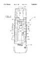
- FIG. 1is an elevational view of a cleaner hard bag housing of a vacuum cleaner with the hard bag cover removed and which mountingly incorporates the invention
- FIG. 2is an elevational view of a housing cap for the cleaner hard bag and provided for encapsulation of the dirt sensing circuit;
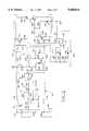
- FIG. 3is a circuit diagram of the audio dirt sensing circuit of the invention.
- FIG. 1a hard bag housing 12 of a vacuum cleaner 10 which would normally cover and house a dirt collecting bag (not shown).
- the hard bag housing 12is generally U-shaped in plan section and includes angled, outwardly vertically extending leg walls 14, 14 having a series of horizontally extending ribs 16, 16 that extend between and space the walls 14, 14 from inner generally parallel walls 18, 18. These dual walls serve to strengthen the hard bag housing 12.
- These inner walls 18, 18also have a series of short ribs 20, 20 which are elongated inwardly to terminate at a pair of inwardly disposed ribbed semi-arched panel sections 22, 24 that are both offset inwardly into the internal volume of the hard bag housing 12 relative to a generally, centrally outwardly disposed portion 26 forming the central section of the bight of this housing's plan U-shape.
- This generally completes the description of the hard bag housing 12which will be here given since it is exemplary only and may take many forms and merely serves a lodgment and a supporting means for the inventive dirt sensor circuitry.
- An upper fill tube 28is attached at its bottom duct portion 30 to an inner hollow telescoping member of similar shape (not shown) and integral with bottom portions of the bag housing 12. This connection forms a fluid tight communication between it and the motor-fan system (not shown) for the vacuum cleaner 10. This motor-fan system may be partially lodged at the bottom of hard bag housing 12 in an integral half cylindrical housing portion 32 provided for this purpose.
- Upper fill tube 28is integrally extended above bottom duct portion 30 by an upper duct portion 34 of smaller rectangular cross-sectional shape than bottom duct portion 30.
- a pair of fastening screws 36, 38attach the upper duct portion 34 of upper fill tube 28 to the hard bag housing 12.
- Upper fill tube 28includes a right angled bend 40 at its upper end to provide a tubular bag snout for easy connection to a paper bag (not shown) which is to be mounted conventionally within the confines of bag housing 12.
- a short, small, hollow cylindrical boss 44At the outer surface of rear side 42 of the right angled bend 40, immediately outside the area of most dirt impingement, (caused by the sharp angle of flow change) is disposed a short, small, hollow cylindrical boss 44. This boss is closed on its inner side by the outer surface of rear side 42 of the upper fill tube 28 to protect its cavity 45 from direct dirt impingement and contact and is open at its outer side for reception of, ideally, a small cylindrical shaped microphone (not shown in FIG. 1).
- FIG. 2a hollow housing cap 46 is shown which provides the console and housing for external display and internal mounting of the dirt sensing circuitry while a battery 78 is lodged in upper portion of the bag housing 12.
- Housing cap 46conveniently may mount (not shown) to the top side of the bag housing by the use of internal screw mounting bosses 48, 48 screwingly attached (not shown) to hard bag housing 12 and locating pins 50, 50 which may be received in apertures (not shown) formed in a top wall 52 of hard bag housing 12.
- Housing cap 46has a curved linear top side 54, curvilinear ends walls 56, 56 and a rear wall 58. Housing cap 46 is completed in outline by a forward angled panel wall 60 that includes a raised bezel 62 that extends longitudinally horizontally along a front face 64 of forward panel wall 60.
- the raised bezel 62mountingly includes a pair of red and green lenses 66, 68 and a raised mounting aperture 70 for a switch (to be later described).
- the housing cap 46is generally completed by an access aperture 72 having at its bottom side an inwardly extending barbed hook 74 that may conveniently aid in maintaining (not shown) the combined electronic circuitry and battery pack of the dirt sensing arrangement, to be described later, securely on and stationary with the top of the bag housing 12.
- a dirt sensing circuitry 76is shown in FIG. 3. It includes the battery 78 attached across a pair of power input terminals 80, 82, with the negative input line of the battery 78 (terminal 82) having a switch 84, ideally a conventional rocker switch interposed in series relation with it.
- This switchis normally in the open position when the vacuum cleaner 10 is in an inoperative, switch off position and is closed when the cleaner is turned “on” and a handle mounted rod (not shown), e.g., somewhat similar to that shown in U.S. Pat. No. 5,226,527, issued Jul. 13, 1993 and owned by a common assignee is moved downwardly to turn on the main body nozzle mounted motor (not shown) for normal cleaner operation.
- This switchagain opens when the switch rod (not shown) is reciprocated upwardly to turn the vacuum cleaner "off".
- a direct manually actuated switchcould also be used or even a pressure operated switch activated by cleaner suction.
- a conventional audio microphone 86such as a microphone sold by Radio Shack Tandy Corporation®, such as, a conventional Electret Condenser Microphone, advertised as having an audiorange of 20 to 20,000 Hz. It is also connected across a pair of input terminals of the dirt sensing circuit 76 including the input terminal 80 and an input terminal 88. This microphone, as previously described, is mounted in hollow boss 44. A shunt also extends from input terminal 88 to negative input terminal 82.
- the electrical signals produced by the microphone 86 by the audible signals occurring through cleaner motor noise, air movement through the upper fill tube and dirt impingement on the rear side 42 of upper fill tube 28provide pulses, the first raw signals, to the remainder of the dirt sensing circuit 76. It has been found that this microphone by Frequency Spectra analysis provides a higher signal to noise ratio and is more effective in the 16,000 to 40,000 Hz range. Selecting this band of frequencies will enable the dirt sensing circuit 76 to detect most types of dirt. These pulses are fed to a two stage high pass filter amplifier 90.
- Amplifier 90has a formed first stage 92 having an operational amplifier 94 (available commercially as a UG324 chip), a capacitor 96 and resistances 98, 100 and a second stage 101 consisting of a capacitor 102, resistance 104, 106 and a second amplifier 108 (UG324).
- This portion of the circuitamplifies its incoming signal since the capacitors and their associated resistance form a first impedance (Z1) and the other resistance in each stage forms a second impedance (Z2). Since capacitor reactance approaches zero at higher frequencies then only the higher frequency components are amplified.
- a bias resistor 91is provided in the line extending from the terminal 80 for the microphone 86.
- the dirt sensing circuit 76also includes a capacitor 118 and a pair of resistors 120, 122 which forms a last stage of high pass filtering and level shifting to trigger a multivibrator 136 when signals above the background noise level are detected.
- These resistorsare connected across the input lines 80 and 88 and have a juncture 124 of the connecting lines joined to the capacitor 118 which is also connected to the output of the second operational amplifier 108 of the chip (UG324).
- Capacitor 118decouples the bias voltage established by the juncture 114.
- Resistors 120 and 122use the voltage divider rule to establish a DC bias voltage for the third operational amplifier 126.
- the Juncture 124is connected by a line to this third operational amplifier.
- the resistors 120, 122 and the capacitor 118form, functionally, a passive high pass filter 121.
- Operational amplifier 126(the third chip--UG324), a first diode 128 (IN 914), a resistance 130 a second diode 132 (IN 914), and a capacitor 134, all of which are connected to the third operational amplifier 126 form a conventional multivibrator or pulse stretcher 136.
- These electrical components forming the multivibrator 136function to take a narrow electrical pulse of approximately 25 microsecond wide from the juncture 124 and stretch it to approximately 8 millisecond wide to facilitate consistent integration.
- the generation of the 8 millisecond pulseis made possible at least in part by the first diode 128 which prevents the voltage at 124 from being driven below ground potential by more than 0.7 volts.
- the operations of such a conventional multivibratoris described, e.g., on page AN 74-10, Linear Applications Handbook, National Semiconductor Corporation, 1978.
- This pulseis then fed to an integrating section 138 where the rate of integration "high” or “low” is selected by switch 150.
- the integratorWith the switch in the "high” sensitivity mode, the integrator is formed by resistors 139, 140, diode 146, juncture 152 and capacitor 181.
- the integratorWith the switch in the "low” sensitivity mode, the integrator is formed by resistors 142, 144, diode 148, juncture 154 and capacitor 181.
- the dirt detection circuitryWhen switch 150 is in the high sensitivity mode, the dirt detection circuitry will require a minimum of three pulses, 8 millisecond wide, at a rate of 120 pulses per second to activate (turn on) the RED light emitting diode 156, giving a response time (time to turn on) of 0.025 seconds.
- the dirt detection circuitryWhen switch 150 is in the low sensitivity mode, the dirt detection circuitry will require a minimum of six pulses, 8 millisecond wide, at a rate of 120 pulses per second to activate (turn on) the RED light emitting diode 156 giving a response time (time to turn on) of 0.056 seconds. This time is measured from the rising edge of the first 8 millisecond wide pulse (generated by the multivibrator 136) to the switching from the low to high of the schmitt trigger comparator output. This is all occasioned by the named components controlling the rate of integration in one of two manners as dictated by the switch 150 and, therefore, the response time of the system.
- the dirt sensing circuit 76is completed by an indicating section 190 including a fourth amplifier 158 (UG324) used as a schmitt trigger comparator.
- a fourth amplifier 158(UG324) used as a schmitt trigger comparator.
- the upper trip point of the comparatoris established by a voltage divider consisting of resistors 166 and 178 and has a juncture 180. These resistors are connected across the input lines 80 and 88 and has the juncture 180 of the connecting lines joined to the fourth operational amplifier 158 (fourth chip). Resistors 179 and 160 provides the hysteresis to establish the lower trip point.
- the green LEDis lit when the base of the transistor 177 is held at least 0.7 volts below the collector voltage; this happens when the output of operational amplifier 158 is in its low state.
- a review of a single such a comparatorgenerally may be found on page AN 74-4 of the above cited publication.
- comparator 158When the system is in its normal mode "no dirt detected" the output of comparator 158 is low 0 volts holding the base of transistor 177 at 0.7 volts below its emitter enabling the greed led 170 to light. When dirt is detected by the circuit 76 and the integrated pulses produces a voltage at juncture 183 greater than the upper threshold established at juncture 180 the comparator 158 will go to the high state turning on the red LED 156 and at the same time raising the base voltage of transistor 177 above the emitter voltage thus turning off the green led 170.
Landscapes
- Engineering & Computer Science (AREA)
- Mechanical Engineering (AREA)
- Geophysics And Detection Of Objects (AREA)
Abstract
Description
Claims (8)
Priority Applications (1)
| Application Number | Priority Date | Filing Date | Title |
|---|---|---|---|
| US08/461,151US5608944A (en) | 1995-06-05 | 1995-06-05 | Vacuum cleaner with dirt detection |
Applications Claiming Priority (1)
| Application Number | Priority Date | Filing Date | Title |
|---|---|---|---|
| US08/461,151US5608944A (en) | 1995-06-05 | 1995-06-05 | Vacuum cleaner with dirt detection |
Publications (1)
| Publication Number | Publication Date |
|---|---|
| US5608944Atrue US5608944A (en) | 1997-03-11 |
Family
ID=23831414
Family Applications (1)
| Application Number | Title | Priority Date | Filing Date |
|---|---|---|---|
| US08/461,151Expired - LifetimeUS5608944A (en) | 1995-06-05 | 1995-06-05 | Vacuum cleaner with dirt detection |
Country Status (1)
| Country | Link |
|---|---|
| US (1) | US5608944A (en) |
Cited By (51)
| Publication number | Priority date | Publication date | Assignee | Title |
|---|---|---|---|---|
| US6023814A (en)* | 1997-09-15 | 2000-02-15 | Imamura; Nobuo | Vacuum cleaner |
| US6446302B1 (en)* | 1999-06-14 | 2002-09-10 | Bissell Homecare, Inc. | Extraction cleaning machine with cleaning control |
| US20020174507A1 (en)* | 1999-06-14 | 2002-11-28 | Kasper Gary A. | Extraction cleaner with power drive |
| US6571422B1 (en) | 2000-08-01 | 2003-06-03 | The Hoover Company | Vacuum cleaner with a microprocessor-based dirt detection circuit |
| US20030204930A1 (en)* | 2000-01-14 | 2003-11-06 | Thomas Hawkins | Upright vacuum cleaner with cyclonic air path |
| US20040049877A1 (en)* | 2002-01-03 | 2004-03-18 | Jones Joseph L. | Autonomous floor-cleaning robot |
| US20040187249A1 (en)* | 2002-01-03 | 2004-09-30 | Jones Joseph L. | Autonomous floor-cleaning robot |
| US6800140B2 (en) | 2000-06-13 | 2004-10-05 | Bissell Homecare, Inc. | Extraction cleaning with optimal cleaning speed |
| US6812847B1 (en)* | 2000-08-25 | 2004-11-02 | The Hoover Company | Moisture indicator for wet pick-up suction cleaner |
| US20040216264A1 (en)* | 2003-02-26 | 2004-11-04 | Shaver David M. | Hand vacuum with filter indicator |
| US20050156562A1 (en)* | 2004-01-21 | 2005-07-21 | Irobot Corporation | Autonomous robot auto-docking and energy management systems and methods |
| US20050241101A1 (en)* | 2000-01-14 | 2005-11-03 | Sepke Arnold L | Bagless dustcup |
| US20050279059A1 (en)* | 2004-06-22 | 2005-12-22 | Samsung Electronics Co., Ltd. | Air purifier and control method thereof |
| US20050287038A1 (en)* | 2004-06-24 | 2005-12-29 | Zivthan Dubrovsky | Remote control scheduler and method for autonomous robotic device |
| US20060190134A1 (en)* | 2005-02-18 | 2006-08-24 | Irobot Corporation | Autonomous surface cleaning robot for wet and dry cleaning |
| US20060190146A1 (en)* | 2005-02-18 | 2006-08-24 | Irobot Corporation | Autonomous surface cleaning robot for dry cleaning |
| US7155308B2 (en) | 2000-01-24 | 2006-12-26 | Irobot Corporation | Robot obstacle detection system |
| WO2007033977A1 (en)* | 2005-09-23 | 2007-03-29 | Vorwerk & Co. Interholding Gmbh | Method for generating a signal for changing a filter bag and vacuum cleaner comprising a suction blower |
| US20070069680A1 (en)* | 2004-01-28 | 2007-03-29 | Landry Gregg W | Debris Sensor for Cleaning Apparatus |
| CN100358459C (en)* | 2000-08-25 | 2008-01-02 | 胡佛公司 | Moisture Indicators for Hygrovacs |
| US20080052846A1 (en)* | 2006-05-19 | 2008-03-06 | Irobot Corporation | Cleaning robot roller processing |
| US20080281470A1 (en)* | 2007-05-09 | 2008-11-13 | Irobot Corporation | Autonomous coverage robot sensing |
| US20080282494A1 (en)* | 2005-12-02 | 2008-11-20 | Irobot Corporation | Modular robot |
| US20080301899A1 (en)* | 2007-06-08 | 2008-12-11 | Tacony Corporation | Vacuum Cleaner with Sensing System |
| US20090174564A1 (en)* | 2008-01-09 | 2009-07-09 | Hong Fu Jin Precision Industry (Shenzhen) Co., Ltd. | Dust detecting circuit |
| US7706917B1 (en) | 2004-07-07 | 2010-04-27 | Irobot Corporation | Celestial navigation system for an autonomous robot |
| US7761954B2 (en) | 2005-02-18 | 2010-07-27 | Irobot Corporation | Autonomous surface cleaning robot for wet and dry cleaning |
| US20100270535A1 (en)* | 2005-12-22 | 2010-10-28 | Mears Technologies, Inc. | Electronic device including an electrically polled superlattice and related methods |
| US8368339B2 (en) | 2001-01-24 | 2013-02-05 | Irobot Corporation | Robot confinement |
| US8374721B2 (en) | 2005-12-02 | 2013-02-12 | Irobot Corporation | Robot system |
| US8380350B2 (en) | 2005-12-02 | 2013-02-19 | Irobot Corporation | Autonomous coverage robot navigation system |
| US8386081B2 (en) | 2002-09-13 | 2013-02-26 | Irobot Corporation | Navigational control system for a robotic device |
| US8382906B2 (en) | 2005-02-18 | 2013-02-26 | Irobot Corporation | Autonomous surface cleaning robot for wet cleaning |
| US8396592B2 (en) | 2001-06-12 | 2013-03-12 | Irobot Corporation | Method and system for multi-mode coverage for an autonomous robot |
| US8412377B2 (en) | 2000-01-24 | 2013-04-02 | Irobot Corporation | Obstacle following sensor scheme for a mobile robot |
| US8417383B2 (en) | 2006-05-31 | 2013-04-09 | Irobot Corporation | Detecting robot stasis |
| US8428778B2 (en) | 2002-09-13 | 2013-04-23 | Irobot Corporation | Navigational control system for a robotic device |
| US8463438B2 (en) | 2001-06-12 | 2013-06-11 | Irobot Corporation | Method and system for multi-mode coverage for an autonomous robot |
| US8515578B2 (en) | 2002-09-13 | 2013-08-20 | Irobot Corporation | Navigational control system for a robotic device |
| US8600553B2 (en) | 2005-12-02 | 2013-12-03 | Irobot Corporation | Coverage robot mobility |
| US8689398B2 (en) | 2009-05-21 | 2014-04-08 | Industrial Technology Research Institute | Cleaning apparatus and detecting method thereof |
| US8780342B2 (en) | 2004-03-29 | 2014-07-15 | Irobot Corporation | Methods and apparatus for position estimation using reflected light sources |
| US8788092B2 (en) | 2000-01-24 | 2014-07-22 | Irobot Corporation | Obstacle following sensor scheme for a mobile robot |
| US8800107B2 (en) | 2010-02-16 | 2014-08-12 | Irobot Corporation | Vacuum brush |
| US8930023B2 (en) | 2009-11-06 | 2015-01-06 | Irobot Corporation | Localization by learning of wave-signal distributions |
| US8972052B2 (en) | 2004-07-07 | 2015-03-03 | Irobot Corporation | Celestial navigation system for an autonomous vehicle |
| US9320398B2 (en) | 2005-12-02 | 2016-04-26 | Irobot Corporation | Autonomous coverage robots |
| EP3287863A1 (en) | 2004-01-28 | 2018-02-28 | iRobot Corporation | Autonomous cleaning apparatus with debris sensor |
| US11039723B2 (en)* | 2019-11-06 | 2021-06-22 | Bissell Inc. | Surface cleaning apparatus |
| US20220018794A1 (en)* | 2018-11-09 | 2022-01-20 | Guangdong Midea White Home Appliance Technology Innovation Center Co., Ltd. | Contact-type detection electrode and movable electric device |
| US11737629B2 (en) | 2019-01-08 | 2023-08-29 | Bissell Inc. | Surface cleaning apparatus |
Citations (16)
| Publication number | Priority date | Publication date | Assignee | Title |
|---|---|---|---|---|
| US1565382A (en)* | 1924-05-07 | 1925-12-15 | Mcclatchie Stanley | Vacuum-cleaner device |
| US3674316A (en)* | 1970-05-14 | 1972-07-04 | Robert J De Brey | Particle monitor |
| DE2336758A1 (en)* | 1972-09-06 | 1974-03-14 | Philips Nv | VACUUM CLEANER WITH REGULATING DEVICE |
| US3989311A (en)* | 1970-05-14 | 1976-11-02 | Debrey Robert J | Particle monitoring apparatus |
| US4099861A (en)* | 1976-11-10 | 1978-07-11 | Eastman Kodak Company | Contamination sensor |
| US4175892A (en)* | 1972-05-10 | 1979-11-27 | Brey Robert J De | Particle monitor |
| US4580311A (en)* | 1984-02-08 | 1986-04-08 | Gerhard Kurz | Protective device for dust collecting devices |
| US4601082A (en)* | 1984-02-08 | 1986-07-22 | Gerhard Kurz | Vacuum cleaner |
| US4767213A (en)* | 1986-02-05 | 1988-08-30 | Interlava Ag | Optical indication and operation monitoring unit for vacuum cleaners |
| US4829626A (en)* | 1986-10-01 | 1989-05-16 | Allaway Oy | Method for controlling a vacuum cleaner or a central vacuum cleaner |
| EP0371632A1 (en)* | 1988-11-07 | 1990-06-06 | Matsushita Electric Industrial Co., Ltd. | Vacuum cleaner with device for adjusting sensitivity of dust sensor |
| GB2225933A (en)* | 1988-12-02 | 1990-06-20 | Hoover Plc | Vacuum cleaner with dirt sensor |
| US5163202A (en)* | 1988-03-24 | 1992-11-17 | Matsushita Electric Industrial Co. Ltd. | Dust detector for vacuum cleaner |
| EP0584743A1 (en)* | 1992-08-21 | 1994-03-02 | YASHIMA ELECTRIC CO., Ltd. of ISHIHARA NOGAMI | Vacuum cleaner |
| US5319827A (en)* | 1991-08-14 | 1994-06-14 | Gold Star Co., Ltd. | Device of sensing dust for a vacuum cleaner |
| US5502869A (en)* | 1993-02-09 | 1996-04-02 | Noise Cancellation Technologies, Inc. | High volume, high performance, ultra quiet vacuum cleaner |
- 1995
- 1995-06-05USUS08/461,151patent/US5608944A/ennot_activeExpired - Lifetime
Patent Citations (18)
| Publication number | Priority date | Publication date | Assignee | Title |
|---|---|---|---|---|
| US1565382A (en)* | 1924-05-07 | 1925-12-15 | Mcclatchie Stanley | Vacuum-cleaner device |
| US3674316A (en)* | 1970-05-14 | 1972-07-04 | Robert J De Brey | Particle monitor |
| US3989311A (en)* | 1970-05-14 | 1976-11-02 | Debrey Robert J | Particle monitoring apparatus |
| US4175892A (en)* | 1972-05-10 | 1979-11-27 | Brey Robert J De | Particle monitor |
| DE2336758A1 (en)* | 1972-09-06 | 1974-03-14 | Philips Nv | VACUUM CLEANER WITH REGULATING DEVICE |
| US4099861A (en)* | 1976-11-10 | 1978-07-11 | Eastman Kodak Company | Contamination sensor |
| US4601082C1 (en)* | 1984-02-08 | 2001-04-24 | Interlava Ag | Vacuum cleaner |
| US4580311A (en)* | 1984-02-08 | 1986-04-08 | Gerhard Kurz | Protective device for dust collecting devices |
| US4601082A (en)* | 1984-02-08 | 1986-07-22 | Gerhard Kurz | Vacuum cleaner |
| US4767213A (en)* | 1986-02-05 | 1988-08-30 | Interlava Ag | Optical indication and operation monitoring unit for vacuum cleaners |
| US4829626A (en)* | 1986-10-01 | 1989-05-16 | Allaway Oy | Method for controlling a vacuum cleaner or a central vacuum cleaner |
| US5163202A (en)* | 1988-03-24 | 1992-11-17 | Matsushita Electric Industrial Co. Ltd. | Dust detector for vacuum cleaner |
| EP0371632A1 (en)* | 1988-11-07 | 1990-06-06 | Matsushita Electric Industrial Co., Ltd. | Vacuum cleaner with device for adjusting sensitivity of dust sensor |
| US5136750A (en)* | 1988-11-07 | 1992-08-11 | Matsushita Electric Industrial Co., Ltd. | Vacuum cleaner with device for adjusting sensitivity of dust sensor |
| GB2225933A (en)* | 1988-12-02 | 1990-06-20 | Hoover Plc | Vacuum cleaner with dirt sensor |
| US5319827A (en)* | 1991-08-14 | 1994-06-14 | Gold Star Co., Ltd. | Device of sensing dust for a vacuum cleaner |
| EP0584743A1 (en)* | 1992-08-21 | 1994-03-02 | YASHIMA ELECTRIC CO., Ltd. of ISHIHARA NOGAMI | Vacuum cleaner |
| US5502869A (en)* | 1993-02-09 | 1996-04-02 | Noise Cancellation Technologies, Inc. | High volume, high performance, ultra quiet vacuum cleaner |
Cited By (156)
| Publication number | Priority date | Publication date | Assignee | Title |
|---|---|---|---|---|
| US6023814A (en)* | 1997-09-15 | 2000-02-15 | Imamura; Nobuo | Vacuum cleaner |
| US6446302B1 (en)* | 1999-06-14 | 2002-09-10 | Bissell Homecare, Inc. | Extraction cleaning machine with cleaning control |
| US20020174507A1 (en)* | 1999-06-14 | 2002-11-28 | Kasper Gary A. | Extraction cleaner with power drive |
| US7062816B2 (en) | 1999-06-14 | 2006-06-20 | Bissell Homecare, Inc. | Surface cleaner with power drive |
| US7163568B2 (en) | 2000-01-14 | 2007-01-16 | Electrolux Home Care Products Ltd. | Bagless dustcup |
| US7228592B2 (en) | 2000-01-14 | 2007-06-12 | Electrolux Homecare Products Ltd. | Upright vacuum cleaner with cyclonic air path |
| US20030204930A1 (en)* | 2000-01-14 | 2003-11-06 | Thomas Hawkins | Upright vacuum cleaner with cyclonic air path |
| US20050241101A1 (en)* | 2000-01-14 | 2005-11-03 | Sepke Arnold L | Bagless dustcup |
| US20060070207A1 (en)* | 2000-01-14 | 2006-04-06 | Thomas Hawkins | Upright vacuum cleaner with cyclonic air path |
| US8412377B2 (en) | 2000-01-24 | 2013-04-02 | Irobot Corporation | Obstacle following sensor scheme for a mobile robot |
| US8761935B2 (en) | 2000-01-24 | 2014-06-24 | Irobot Corporation | Obstacle following sensor scheme for a mobile robot |
| US8565920B2 (en) | 2000-01-24 | 2013-10-22 | Irobot Corporation | Obstacle following sensor scheme for a mobile robot |
| US8788092B2 (en) | 2000-01-24 | 2014-07-22 | Irobot Corporation | Obstacle following sensor scheme for a mobile robot |
| US7155308B2 (en) | 2000-01-24 | 2006-12-26 | Irobot Corporation | Robot obstacle detection system |
| US8478442B2 (en) | 2000-01-24 | 2013-07-02 | Irobot Corporation | Obstacle following sensor scheme for a mobile robot |
| US9446521B2 (en) | 2000-01-24 | 2016-09-20 | Irobot Corporation | Obstacle following sensor scheme for a mobile robot |
| US9144361B2 (en) | 2000-04-04 | 2015-09-29 | Irobot Corporation | Debris sensor for cleaning apparatus |
| US6800140B2 (en) | 2000-06-13 | 2004-10-05 | Bissell Homecare, Inc. | Extraction cleaning with optimal cleaning speed |
| US6571422B1 (en) | 2000-08-01 | 2003-06-03 | The Hoover Company | Vacuum cleaner with a microprocessor-based dirt detection circuit |
| CN100358459C (en)* | 2000-08-25 | 2008-01-02 | 胡佛公司 | Moisture Indicators for Hygrovacs |
| US6812847B1 (en)* | 2000-08-25 | 2004-11-02 | The Hoover Company | Moisture indicator for wet pick-up suction cleaner |
| US8686679B2 (en) | 2001-01-24 | 2014-04-01 | Irobot Corporation | Robot confinement |
| US8368339B2 (en) | 2001-01-24 | 2013-02-05 | Irobot Corporation | Robot confinement |
| US9622635B2 (en) | 2001-01-24 | 2017-04-18 | Irobot Corporation | Autonomous floor-cleaning robot |
| US20080000042A1 (en)* | 2001-01-24 | 2008-01-03 | Irobot Corporation | Autonomous Floor Cleaning Robot |
| US9582005B2 (en) | 2001-01-24 | 2017-02-28 | Irobot Corporation | Robot confinement |
| US9038233B2 (en) | 2001-01-24 | 2015-05-26 | Irobot Corporation | Autonomous floor-cleaning robot |
| US9167946B2 (en) | 2001-01-24 | 2015-10-27 | Irobot Corporation | Autonomous floor cleaning robot |
| US8396592B2 (en) | 2001-06-12 | 2013-03-12 | Irobot Corporation | Method and system for multi-mode coverage for an autonomous robot |
| US9104204B2 (en) | 2001-06-12 | 2015-08-11 | Irobot Corporation | Method and system for multi-mode coverage for an autonomous robot |
| US8463438B2 (en) | 2001-06-12 | 2013-06-11 | Irobot Corporation | Method and system for multi-mode coverage for an autonomous robot |
| US8656550B2 (en) | 2002-01-03 | 2014-02-25 | Irobot Corporation | Autonomous floor-cleaning robot |
| US6883201B2 (en) | 2002-01-03 | 2005-04-26 | Irobot Corporation | Autonomous floor-cleaning robot |
| US8763199B2 (en) | 2002-01-03 | 2014-07-01 | Irobot Corporation | Autonomous floor-cleaning robot |
| US20100257691A1 (en)* | 2002-01-03 | 2010-10-14 | Irobot Corporation | Autonomous floor-cleaning robot |
| US8474090B2 (en) | 2002-01-03 | 2013-07-02 | Irobot Corporation | Autonomous floor-cleaning robot |
| US20080307590A1 (en)* | 2002-01-03 | 2008-12-18 | Irobot Corporation | Autonomous Floor-Cleaning Robot |
| US8516651B2 (en) | 2002-01-03 | 2013-08-27 | Irobot Corporation | Autonomous floor-cleaning robot |
| US8671507B2 (en) | 2002-01-03 | 2014-03-18 | Irobot Corporation | Autonomous floor-cleaning robot |
| US7571511B2 (en) | 2002-01-03 | 2009-08-11 | Irobot Corporation | Autonomous floor-cleaning robot |
| US20100257690A1 (en)* | 2002-01-03 | 2010-10-14 | Irobot Corporation | Autonomous floor-cleaning robot |
| US20040187249A1 (en)* | 2002-01-03 | 2004-09-30 | Jones Joseph L. | Autonomous floor-cleaning robot |
| US20040049877A1 (en)* | 2002-01-03 | 2004-03-18 | Jones Joseph L. | Autonomous floor-cleaning robot |
| US20100263158A1 (en)* | 2002-01-03 | 2010-10-21 | Irobot Corporation | Autonomous floor-cleaning robot |
| US9128486B2 (en) | 2002-01-24 | 2015-09-08 | Irobot Corporation | Navigational control system for a robotic device |
| US9949608B2 (en) | 2002-09-13 | 2018-04-24 | Irobot Corporation | Navigational control system for a robotic device |
| US8781626B2 (en) | 2002-09-13 | 2014-07-15 | Irobot Corporation | Navigational control system for a robotic device |
| US8793020B2 (en) | 2002-09-13 | 2014-07-29 | Irobot Corporation | Navigational control system for a robotic device |
| US8515578B2 (en) | 2002-09-13 | 2013-08-20 | Irobot Corporation | Navigational control system for a robotic device |
| US8428778B2 (en) | 2002-09-13 | 2013-04-23 | Irobot Corporation | Navigational control system for a robotic device |
| US8386081B2 (en) | 2002-09-13 | 2013-02-26 | Irobot Corporation | Navigational control system for a robotic device |
| US20040216264A1 (en)* | 2003-02-26 | 2004-11-04 | Shaver David M. | Hand vacuum with filter indicator |
| US7418763B2 (en) | 2003-02-26 | 2008-09-02 | Black & Decker Inc. | Hand vacuum with filter indicator |
| US20080244858A1 (en)* | 2003-02-26 | 2008-10-09 | Shaver David M | Hand vacuum with filter indicator |
| US8461803B2 (en) | 2004-01-21 | 2013-06-11 | Irobot Corporation | Autonomous robot auto-docking and energy management systems and methods |
| US7332890B2 (en) | 2004-01-21 | 2008-02-19 | Irobot Corporation | Autonomous robot auto-docking and energy management systems and methods |
| US8854001B2 (en) | 2004-01-21 | 2014-10-07 | Irobot Corporation | Autonomous robot auto-docking and energy management systems and methods |
| US20050156562A1 (en)* | 2004-01-21 | 2005-07-21 | Irobot Corporation | Autonomous robot auto-docking and energy management systems and methods |
| US8390251B2 (en) | 2004-01-21 | 2013-03-05 | Irobot Corporation | Autonomous robot auto-docking and energy management systems and methods |
| US8749196B2 (en) | 2004-01-21 | 2014-06-10 | Irobot Corporation | Autonomous robot auto-docking and energy management systems and methods |
| US9215957B2 (en) | 2004-01-21 | 2015-12-22 | Irobot Corporation | Autonomous robot auto-docking and energy management systems and methods |
| US7288912B2 (en) | 2004-01-28 | 2007-10-30 | Irobot Corporation | Debris sensor for cleaning apparatus |
| US8378613B2 (en) | 2004-01-28 | 2013-02-19 | Irobot Corporation | Debris sensor for cleaning apparatus |
| US8253368B2 (en) | 2004-01-28 | 2012-08-28 | Irobot Corporation | Debris sensor for cleaning apparatus |
| US20070069680A1 (en)* | 2004-01-28 | 2007-03-29 | Landry Gregg W | Debris Sensor for Cleaning Apparatus |
| US8456125B2 (en) | 2004-01-28 | 2013-06-04 | Irobot Corporation | Debris sensor for cleaning apparatus |
| EP3287863A1 (en) | 2004-01-28 | 2018-02-28 | iRobot Corporation | Autonomous cleaning apparatus with debris sensor |
| US20090038089A1 (en)* | 2004-01-28 | 2009-02-12 | Irobot Corporation | Debris Sensor for Cleaning Apparatus |
| US8780342B2 (en) | 2004-03-29 | 2014-07-15 | Irobot Corporation | Methods and apparatus for position estimation using reflected light sources |
| US9360300B2 (en) | 2004-03-29 | 2016-06-07 | Irobot Corporation | Methods and apparatus for position estimation using reflected light sources |
| US20050279059A1 (en)* | 2004-06-22 | 2005-12-22 | Samsung Electronics Co., Ltd. | Air purifier and control method thereof |
| US9486924B2 (en) | 2004-06-24 | 2016-11-08 | Irobot Corporation | Remote control scheduler and method for autonomous robotic device |
| US9008835B2 (en) | 2004-06-24 | 2015-04-14 | Irobot Corporation | Remote control scheduler and method for autonomous robotic device |
| US20050287038A1 (en)* | 2004-06-24 | 2005-12-29 | Zivthan Dubrovsky | Remote control scheduler and method for autonomous robotic device |
| US8634956B1 (en) | 2004-07-07 | 2014-01-21 | Irobot Corporation | Celestial navigation system for an autonomous robot |
| US9229454B1 (en) | 2004-07-07 | 2016-01-05 | Irobot Corporation | Autonomous mobile robot system |
| US8874264B1 (en) | 2004-07-07 | 2014-10-28 | Irobot Corporation | Celestial navigation system for an autonomous robot |
| US8594840B1 (en) | 2004-07-07 | 2013-11-26 | Irobot Corporation | Celestial navigation system for an autonomous robot |
| US8972052B2 (en) | 2004-07-07 | 2015-03-03 | Irobot Corporation | Celestial navigation system for an autonomous vehicle |
| US7706917B1 (en) | 2004-07-07 | 2010-04-27 | Irobot Corporation | Celestial navigation system for an autonomous robot |
| US9223749B2 (en) | 2004-07-07 | 2015-12-29 | Irobot Corporation | Celestial navigation system for an autonomous vehicle |
| US20080127446A1 (en)* | 2005-02-18 | 2008-06-05 | Irobot Corporation | Autonomous surface cleaning robot for wet and dry cleaning |
| US7761954B2 (en) | 2005-02-18 | 2010-07-27 | Irobot Corporation | Autonomous surface cleaning robot for wet and dry cleaning |
| US7389156B2 (en) | 2005-02-18 | 2008-06-17 | Irobot Corporation | Autonomous surface cleaning robot for wet and dry cleaning |
| US9445702B2 (en) | 2005-02-18 | 2016-09-20 | Irobot Corporation | Autonomous surface cleaning robot for wet and dry cleaning |
| US8855813B2 (en) | 2005-02-18 | 2014-10-07 | Irobot Corporation | Autonomous surface cleaning robot for wet and dry cleaning |
| US10470629B2 (en) | 2005-02-18 | 2019-11-12 | Irobot Corporation | Autonomous surface cleaning robot for dry cleaning |
| US8739355B2 (en) | 2005-02-18 | 2014-06-03 | Irobot Corporation | Autonomous surface cleaning robot for dry cleaning |
| US8387193B2 (en) | 2005-02-18 | 2013-03-05 | Irobot Corporation | Autonomous surface cleaning robot for wet and dry cleaning |
| US7620476B2 (en) | 2005-02-18 | 2009-11-17 | Irobot Corporation | Autonomous surface cleaning robot for dry cleaning |
| US8392021B2 (en) | 2005-02-18 | 2013-03-05 | Irobot Corporation | Autonomous surface cleaning robot for wet cleaning |
| US8382906B2 (en) | 2005-02-18 | 2013-02-26 | Irobot Corporation | Autonomous surface cleaning robot for wet cleaning |
| US8774966B2 (en) | 2005-02-18 | 2014-07-08 | Irobot Corporation | Autonomous surface cleaning robot for wet and dry cleaning |
| US20060190146A1 (en)* | 2005-02-18 | 2006-08-24 | Irobot Corporation | Autonomous surface cleaning robot for dry cleaning |
| US8670866B2 (en) | 2005-02-18 | 2014-03-11 | Irobot Corporation | Autonomous surface cleaning robot for wet and dry cleaning |
| US8985127B2 (en) | 2005-02-18 | 2015-03-24 | Irobot Corporation | Autonomous surface cleaning robot for wet cleaning |
| US8782848B2 (en) | 2005-02-18 | 2014-07-22 | Irobot Corporation | Autonomous surface cleaning robot for dry cleaning |
| US20060190134A1 (en)* | 2005-02-18 | 2006-08-24 | Irobot Corporation | Autonomous surface cleaning robot for wet and dry cleaning |
| US8966707B2 (en) | 2005-02-18 | 2015-03-03 | Irobot Corporation | Autonomous surface cleaning robot for dry cleaning |
| WO2007033977A1 (en)* | 2005-09-23 | 2007-03-29 | Vorwerk & Co. Interholding Gmbh | Method for generating a signal for changing a filter bag and vacuum cleaner comprising a suction blower |
| US9149170B2 (en) | 2005-12-02 | 2015-10-06 | Irobot Corporation | Navigating autonomous coverage robots |
| US10524629B2 (en) | 2005-12-02 | 2020-01-07 | Irobot Corporation | Modular Robot |
| US8584305B2 (en) | 2005-12-02 | 2013-11-19 | Irobot Corporation | Modular robot |
| US8600553B2 (en) | 2005-12-02 | 2013-12-03 | Irobot Corporation | Coverage robot mobility |
| US8954192B2 (en) | 2005-12-02 | 2015-02-10 | Irobot Corporation | Navigating autonomous coverage robots |
| US8950038B2 (en) | 2005-12-02 | 2015-02-10 | Irobot Corporation | Modular robot |
| US9599990B2 (en) | 2005-12-02 | 2017-03-21 | Irobot Corporation | Robot system |
| US8661605B2 (en) | 2005-12-02 | 2014-03-04 | Irobot Corporation | Coverage robot mobility |
| US8978196B2 (en) | 2005-12-02 | 2015-03-17 | Irobot Corporation | Coverage robot mobility |
| US9392920B2 (en) | 2005-12-02 | 2016-07-19 | Irobot Corporation | Robot system |
| US8374721B2 (en) | 2005-12-02 | 2013-02-12 | Irobot Corporation | Robot system |
| US8380350B2 (en) | 2005-12-02 | 2013-02-19 | Irobot Corporation | Autonomous coverage robot navigation system |
| US9320398B2 (en) | 2005-12-02 | 2016-04-26 | Irobot Corporation | Autonomous coverage robots |
| US8761931B2 (en) | 2005-12-02 | 2014-06-24 | Irobot Corporation | Robot system |
| US20080282494A1 (en)* | 2005-12-02 | 2008-11-20 | Irobot Corporation | Modular robot |
| US9144360B2 (en) | 2005-12-02 | 2015-09-29 | Irobot Corporation | Autonomous coverage robot navigation system |
| US20100270535A1 (en)* | 2005-12-22 | 2010-10-28 | Mears Technologies, Inc. | Electronic device including an electrically polled superlattice and related methods |
| US8087117B2 (en) | 2006-05-19 | 2012-01-03 | Irobot Corporation | Cleaning robot roller processing |
| US10244915B2 (en) | 2006-05-19 | 2019-04-02 | Irobot Corporation | Coverage robots and associated cleaning bins |
| US8572799B2 (en) | 2006-05-19 | 2013-11-05 | Irobot Corporation | Removing debris from cleaning robots |
| US9955841B2 (en) | 2006-05-19 | 2018-05-01 | Irobot Corporation | Removing debris from cleaning robots |
| US8528157B2 (en) | 2006-05-19 | 2013-09-10 | Irobot Corporation | Coverage robots and associated cleaning bins |
| US20080052846A1 (en)* | 2006-05-19 | 2008-03-06 | Irobot Corporation | Cleaning robot roller processing |
| US9492048B2 (en) | 2006-05-19 | 2016-11-15 | Irobot Corporation | Removing debris from cleaning robots |
| US8418303B2 (en) | 2006-05-19 | 2013-04-16 | Irobot Corporation | Cleaning robot roller processing |
| US9317038B2 (en) | 2006-05-31 | 2016-04-19 | Irobot Corporation | Detecting robot stasis |
| US8417383B2 (en) | 2006-05-31 | 2013-04-09 | Irobot Corporation | Detecting robot stasis |
| US10070764B2 (en) | 2007-05-09 | 2018-09-11 | Irobot Corporation | Compact autonomous coverage robot |
| US8726454B2 (en) | 2007-05-09 | 2014-05-20 | Irobot Corporation | Autonomous coverage robot |
| US8239992B2 (en) | 2007-05-09 | 2012-08-14 | Irobot Corporation | Compact autonomous coverage robot |
| US20080281470A1 (en)* | 2007-05-09 | 2008-11-13 | Irobot Corporation | Autonomous coverage robot sensing |
| US9480381B2 (en) | 2007-05-09 | 2016-11-01 | Irobot Corporation | Compact autonomous coverage robot |
| US8438695B2 (en) | 2007-05-09 | 2013-05-14 | Irobot Corporation | Autonomous coverage robot sensing |
| US11072250B2 (en) | 2007-05-09 | 2021-07-27 | Irobot Corporation | Autonomous coverage robot sensing |
| US8839477B2 (en) | 2007-05-09 | 2014-09-23 | Irobot Corporation | Compact autonomous coverage robot |
| US10299652B2 (en) | 2007-05-09 | 2019-05-28 | Irobot Corporation | Autonomous coverage robot |
| US11498438B2 (en) | 2007-05-09 | 2022-11-15 | Irobot Corporation | Autonomous coverage robot |
| US20080301899A1 (en)* | 2007-06-08 | 2008-12-11 | Tacony Corporation | Vacuum Cleaner with Sensing System |
| US7627927B2 (en) | 2007-06-08 | 2009-12-08 | Tacony Corporation | Vacuum cleaner with sensing system |
| US20090174564A1 (en)* | 2008-01-09 | 2009-07-09 | Hong Fu Jin Precision Industry (Shenzhen) Co., Ltd. | Dust detecting circuit |
| US8689398B2 (en) | 2009-05-21 | 2014-04-08 | Industrial Technology Research Institute | Cleaning apparatus and detecting method thereof |
| US8930023B2 (en) | 2009-11-06 | 2015-01-06 | Irobot Corporation | Localization by learning of wave-signal distributions |
| US10314449B2 (en) | 2010-02-16 | 2019-06-11 | Irobot Corporation | Vacuum brush |
| US11058271B2 (en) | 2010-02-16 | 2021-07-13 | Irobot Corporation | Vacuum brush |
| US8800107B2 (en) | 2010-02-16 | 2014-08-12 | Irobot Corporation | Vacuum brush |
| US11921072B2 (en)* | 2018-11-09 | 2024-03-05 | Guangdong Midea White Home Appliance Technology Innovation Center Co., Ltd. | Contact-type detection electrode and movable electric device |
| US20220018794A1 (en)* | 2018-11-09 | 2022-01-20 | Guangdong Midea White Home Appliance Technology Innovation Center Co., Ltd. | Contact-type detection electrode and movable electric device |
| US11786097B1 (en) | 2019-01-08 | 2023-10-17 | Bissell Inc. | Surface cleaning apparatus |
| US11737629B2 (en) | 2019-01-08 | 2023-08-29 | Bissell Inc. | Surface cleaning apparatus |
| US11871892B1 (en) | 2019-01-08 | 2024-01-16 | Bissell Inc. | Surface cleaning apparatus |
| US12193622B2 (en) | 2019-01-08 | 2025-01-14 | Bissell Inc. | Surface cleaning apparatus |
| US20210259494A1 (en)* | 2019-11-06 | 2021-08-26 | Bissell Inc. | Surface cleaning apparatus |
| US11039723B2 (en)* | 2019-11-06 | 2021-06-22 | Bissell Inc. | Surface cleaning apparatus |
| US11963657B2 (en)* | 2019-11-06 | 2024-04-23 | Bissell Inc. | Surface cleaning apparatus |
| US20240225396A1 (en)* | 2019-11-06 | 2024-07-11 | Bissell Inc. | Surface cleaning apparatus |
| US12232686B2 (en)* | 2019-11-06 | 2025-02-25 | Bissell Inc. | Surface cleaning apparatus |
Similar Documents
| Publication | Publication Date | Title |
|---|---|---|
| US5608944A (en) | Vacuum cleaner with dirt detection | |
| US6832407B2 (en) | Moisture indicator for wet pick-up suction cleaner | |
| JP3235883B2 (en) | Vacuum cleaner | |
| US6023814A (en) | Vacuum cleaner | |
| US7931716B2 (en) | Handheld cleaning appliance | |
| EP1448963B1 (en) | An infrared detecting circuit | |
| EP0805645B1 (en) | Vacuum cleaner comprising an odour filter | |
| US5831538A (en) | Electrical fire hazard detector | |
| US20190339338A1 (en) | Device for Registering an On State of a Drive Motor or a Tool, and System | |
| US4173755A (en) | Battery-operated body capacitance intrusion alarm apparatus | |
| US7789952B2 (en) | Vacuum appliance filter condition indicator | |
| US20030146739A1 (en) | Method and circuit arrangement for preventing the stand-by discharge of a battery-powered signal evaluation circuit of a sensor | |
| JP4006985B2 (en) | Pyroelectric infrared detector | |
| GB2400544A (en) | Surface moisture and recovered water level detection and indication in wet suction cleaners | |
| CA2566149A1 (en) | Moisture indicator for wet pick-up suction cleaner | |
| US5578825A (en) | Infrared ray sensor driving circuit | |
| US20020153905A1 (en) | Electronic water line tracer | |
| CN216926480U (en) | Dust detection device | |
| JPH10318834A (en) | Pyroelectric infrared sensor | |
| JP2732414B2 (en) | air purifier | |
| JP2597482Y2 (en) | Photoelectric switch | |
| CA1106933A (en) | Body capacitance intrusion alarm apparatus | |
| JP2578934Y2 (en) | Light receiving circuit | |
| JPS5850925A (en) | vacuum cleaner | |
| JPS6142574B2 (en) |
Legal Events
| Date | Code | Title | Description |
|---|---|---|---|
| AS | Assignment | Owner name:HOOVER COMPANY, THE, OHIO Free format text:ASSIGNMENT OF ASSIGNORS INTEREST;ASSIGNOR:GORDON, EVAN A.;REEL/FRAME:007535/0010 Effective date:19950601 | |
| STCF | Information on status: patent grant | Free format text:PATENTED CASE | |
| FPAY | Fee payment | Year of fee payment:4 | |
| FPAY | Fee payment | Year of fee payment:8 | |
| AS | Assignment | Owner name:HEALTHY GAIN INVESTMENTS LIMITED, VIRGIN ISLANDS, Free format text:ASSIGNMENT OF ASSIGNORS INTEREST;ASSIGNOR:THE HOOVER COMPANY;REEL/FRAME:020270/0001 Effective date:20070131 Owner name:HEALTHY GAIN INVESTMENTS LIMITED,VIRGIN ISLANDS, B Free format text:ASSIGNMENT OF ASSIGNORS INTEREST;ASSIGNOR:THE HOOVER COMPANY;REEL/FRAME:020270/0001 Effective date:20070131 | |
| REMI | Maintenance fee reminder mailed | ||
| FPAY | Fee payment | Year of fee payment:12 | |
| SULP | Surcharge for late payment | Year of fee payment:11 | |
| FEPP | Fee payment procedure | Free format text:PAYOR NUMBER ASSIGNED (ORIGINAL EVENT CODE: ASPN); ENTITY STATUS OF PATENT OWNER: LARGE ENTITY |