US5608609A - Outdoor cabinet for electronic equipment - Google Patents
Outdoor cabinet for electronic equipmentDownload PDFInfo
- Publication number
- US5608609A US5608609AUS08/526,618US52661895AUS5608609AUS 5608609 AUS5608609 AUS 5608609AUS 52661895 AUS52661895 AUS 52661895AUS 5608609 AUS5608609 AUS 5608609A
- Authority
- US
- United States
- Prior art keywords
- circuit packs
- cabinet according
- components
- cabinet
- wall
- Prior art date
- Legal status (The legal status is an assumption and is not a legal conclusion. Google has not performed a legal analysis and makes no representation as to the accuracy of the status listed.)
- Expired - Lifetime
Links
Images


Classifications
- H—ELECTRICITY
- H02—GENERATION; CONVERSION OR DISTRIBUTION OF ELECTRIC POWER
- H02B—BOARDS, SUBSTATIONS OR SWITCHING ARRANGEMENTS FOR THE SUPPLY OR DISTRIBUTION OF ELECTRIC POWER
- H02B1/00—Frameworks, boards, panels, desks, casings; Details of substations or switching arrangements
- H02B1/26—Casings; Parts thereof or accessories therefor
- H02B1/50—Pedestal- or pad-mounted casings; Parts thereof or accessories therefor
- H—ELECTRICITY
- H05—ELECTRIC TECHNIQUES NOT OTHERWISE PROVIDED FOR
- H05K—PRINTED CIRCUITS; CASINGS OR CONSTRUCTIONAL DETAILS OF ELECTRIC APPARATUS; MANUFACTURE OF ASSEMBLAGES OF ELECTRICAL COMPONENTS
- H05K7/00—Constructional details common to different types of electric apparatus
- H05K7/20—Modifications to facilitate cooling, ventilating, or heating
- H05K7/20009—Modifications to facilitate cooling, ventilating, or heating using a gaseous coolant in electronic enclosures
Definitions
- This inventionrelates to a cabinet for housing electronic equipment.
- the inventionis a cabinet comprising a first portion which is sealed from the outside environment and includes a plurality of circuit packs mounted therein.
- a second portionis provided adjacent to the first portion and separated therefrom by a wall. The second portion is ventilated and includes mounted therein components electrically connected to the circuit packs in the first portion.
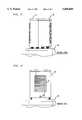
- FIG. 1is an exploded, perspective, schematic view illustrating primarily one side of a cabinet in accordance with one embodiment of the invention
- FIG. 2is an exploded, perspective, schematic view of the same cabinet illustrating essentially another side of the cabinet;
- FIG. 3is a side view of the cabinet of FIGS. 1 and 2;
- FIG. 4is a front view of the cabinet of FIGS. 1 and 2.
- the cabinet, 10,includes two portions, 11 and 12, which are preferably adjacent and separated by a wall, 13.
- Portion 11includes therein a plurality of shelves, e.g., 14, within which are mounted a plurality of circuit packs, e.g., 15 and 16, which are a standard type well known in the art.
- the upper shelf, 14, of portion 11includes the circuit packs (e.g., 15 and 16) for narrowband transmission
- the lower shelf, 18,includes the circuit packs (e.g., 20) for broadband transmission, but other arrangements are possible.
- the various circuit packsare accessed on one end of the cabinet by a door, 17, which is mounted to the rear of the cabinet by means of hinges, e.g., 19.
- An optical fiber organizer, 24,may also be mounted within portion 11 to store optical fibers (not shown) which can carry, for example, telephone and switched digital video signals.
- FIGS. 1 and 2illustrate the access door, 17, in an opened position.
- fastenerssuch as screws
- the other portion, 12, of the cabinetincludes additional electrical components, such as a standard cross-connect apparatus shown schematically as block 22.
- the cross-connect apparatuscan include insulation displacement contacts or binding posts to provide electrical connection from the components in portion 11 to the individual customers by means of one or more output cables (not shown) which exit the cabinet through a hole, 26, in the base, 30.
- the cross-connect apparatus, 22,is coupled to the circuit packs, e.g., 15 and 16, by means of a narrow wire (40) passing through a grommetted aperture (41) in the wall, 13.
- Portion 12also includes standard coaxial cable TV hardware such as a coaxial amplifier, 23, and a plurality of taps, 25, for amplifying and separating rf signals from an incoming coaxial cable (not shown) so the signals can be sent to individual customers through an output coaxial cable (not shown). Again, the input and output coaxial cables would be fed through hole, 26, in the base.
- the cross-connect and CATV componentsdiffer from the circuit packs, 15 and 16, primarily in the fact that the cross-connect and CATV components may be exposed to the outside environment without any significant adverse consequences.
- the portion, 12,may further include a coaxial connector, 27, for receiving wires (not shown) which carry power from an incoming coaxial cable through hole, 26, to the components in portion 11.
- the wall, 13, separating the two portions, 11 and 12,can be made of a metal such as aluminum or steel which conducts heat away from portion, 11, to provide cooling for the components therein. If desired, although more expensive, a heat exchanger could be mounted or built into the wall, 13.
- the portion, 12,is enclosed by a cover, 31, which is mounted on the base, 30.
- the cover, 31,is then secured to the cabinet by a lock, 35 of FIG. 4, secured to a hasp, 36, so that the cabinet is accessed only by the provider's personnel.
- a cover, 32is mounted on the base, 30, so as to enclose portion 11, and is secured to the cabinet by a lock (not shown) secured to a hasp, 33.
- the covers, 31 and 32include a plurality of vents, e.g., 37, running in an essentially parallel, horizontal direction. In this example, 14 vents are included in a cover which measures 25 ⁇ 1.3 cm. Of course, this number can vary, but it is recommended that the cover have at least 75 cm 2 of vent opening area per 1000 cm 2 of enclosure surface area to ensure adequate cooling of the components in the cabinet. It will be appreciated that the covers, 31 and 32, provide both shading to minimize solar loading and security against access to the components by unauthorized personnel.
Landscapes
- Engineering & Computer Science (AREA)
- Microelectronics & Electronic Packaging (AREA)
- Power Engineering (AREA)
- Physics & Mathematics (AREA)
- Thermal Sciences (AREA)
- Cooling Or The Like Of Electrical Apparatus (AREA)
Abstract
Description
Claims (9)
Priority Applications (1)
| Application Number | Priority Date | Filing Date | Title |
|---|---|---|---|
| US08/526,618US5608609A (en) | 1995-09-11 | 1995-09-11 | Outdoor cabinet for electronic equipment |
Applications Claiming Priority (1)
| Application Number | Priority Date | Filing Date | Title |
|---|---|---|---|
| US08/526,618US5608609A (en) | 1995-09-11 | 1995-09-11 | Outdoor cabinet for electronic equipment |
Publications (1)
| Publication Number | Publication Date |
|---|---|
| US5608609Atrue US5608609A (en) | 1997-03-04 |
Family
ID=24098069
Family Applications (1)
| Application Number | Title | Priority Date | Filing Date |
|---|---|---|---|
| US08/526,618Expired - LifetimeUS5608609A (en) | 1995-09-11 | 1995-09-11 | Outdoor cabinet for electronic equipment |
Country Status (1)
| Country | Link |
|---|---|
| US (1) | US5608609A (en) |
Cited By (19)
| Publication number | Priority date | Publication date | Assignee | Title |
|---|---|---|---|---|
| US5734774A (en)* | 1995-11-30 | 1998-03-31 | Lucent Technologies Inc. | Outdoor electronics cabinet |
| US5892872A (en)* | 1997-07-17 | 1999-04-06 | Northern Telecom Limited | Network unit enclosure |
| US6101090A (en)* | 1998-03-24 | 2000-08-08 | Lucent Technologies, Inc. | Electronic apparatus having an environmentally sealed external enclosure |
| FR2793977A1 (en)* | 1999-05-18 | 2000-11-24 | William Beiline | Cabinet for portable mobile phone base station includes strong folding chassis enabling transport and providing mounting base |
| US20020062767A1 (en)* | 2000-11-30 | 2002-05-30 | Walker James T. | Safe |
| WO2003043395A1 (en)* | 2001-11-14 | 2003-05-22 | Minebea Co., Ltd. | Housing component for a device to be ventilated |
| US20040114326A1 (en)* | 2002-12-12 | 2004-06-17 | 3M Innovative Properties Company | Outdoor electronic equipment cabinet |
| USD516769S1 (en) | 2004-10-16 | 2006-03-07 | James Walker | Safe |
| USD516768S1 (en) | 2004-10-16 | 2006-03-07 | James Walker | Safe |
| USD517269S1 (en) | 2004-10-16 | 2006-03-14 | James Walker | Safe |
| USD517770S1 (en) | 2004-10-16 | 2006-03-21 | James Walker | Safe |
| US20060060114A1 (en)* | 2000-11-30 | 2006-03-23 | Walker James T | Security safe |
| US20070082599A1 (en)* | 2005-08-23 | 2007-04-12 | Thomson Licensing | Peripheral skirt intended to be attached underneath the bottom panel of a device, and corresponding device |
| US20070211429A1 (en)* | 2006-03-09 | 2007-09-13 | Kabushiki Kaisha Toshiba | Housing apparatus for heat generating device |
| US20090052132A1 (en)* | 2007-06-12 | 2009-02-26 | Fernandez Pedro A | Heat Exchanger for Outdoor Enclosures |
| DE112007001920T5 (en) | 2006-08-16 | 2009-06-25 | Siemens Medical Solutions Usa, Inc. | Switching layers for an ultrasonic transducer assembly |
| US20100059270A1 (en)* | 2008-09-11 | 2010-03-11 | Joseph Yeh | Hybrid cooling system for outdoor electronics enclosure |
| EP2337435A1 (en)* | 2009-12-17 | 2011-06-22 | Alcatel Lucent | Flexible telecommunication cabinet |
| US9916737B2 (en) | 2015-09-11 | 2018-03-13 | Wal-Mart Stores, Inc. | Modularizable register |
Citations (7)
| Publication number | Priority date | Publication date | Assignee | Title |
|---|---|---|---|---|
| US4359085A (en)* | 1978-11-24 | 1982-11-16 | Siemens Aktiengesellschaft | Installation for several sound and/or heat emitting machines capable of being installed in a workroom |
| US4495780A (en)* | 1981-12-09 | 1985-01-29 | Hitachi, Ltd. | Cooling method and apparatus for hermetic type control box |
| US4535386A (en)* | 1983-05-23 | 1985-08-13 | Allen-Bradley Company | Natural convection cooling system for electronic components |
| JPH01253997A (en)* | 1988-04-01 | 1989-10-11 | Mitsubishi Electric Corp | Natural air cooled housing of outdoor installation |
| JPH0415999A (en)* | 1990-05-09 | 1992-01-21 | Mitsubishi Electric Corp | Electrical equipment storage device |
| US5150277A (en)* | 1990-05-04 | 1992-09-22 | At&T Bell Laboratories | Cooling of electronic equipment cabinets |
| US5450272A (en)* | 1993-12-02 | 1995-09-12 | Northern Telecom Limited | Telecommunications equipment |
- 1995
- 1995-09-11USUS08/526,618patent/US5608609A/ennot_activeExpired - Lifetime
Patent Citations (7)
| Publication number | Priority date | Publication date | Assignee | Title |
|---|---|---|---|---|
| US4359085A (en)* | 1978-11-24 | 1982-11-16 | Siemens Aktiengesellschaft | Installation for several sound and/or heat emitting machines capable of being installed in a workroom |
| US4495780A (en)* | 1981-12-09 | 1985-01-29 | Hitachi, Ltd. | Cooling method and apparatus for hermetic type control box |
| US4535386A (en)* | 1983-05-23 | 1985-08-13 | Allen-Bradley Company | Natural convection cooling system for electronic components |
| JPH01253997A (en)* | 1988-04-01 | 1989-10-11 | Mitsubishi Electric Corp | Natural air cooled housing of outdoor installation |
| US5150277A (en)* | 1990-05-04 | 1992-09-22 | At&T Bell Laboratories | Cooling of electronic equipment cabinets |
| JPH0415999A (en)* | 1990-05-09 | 1992-01-21 | Mitsubishi Electric Corp | Electrical equipment storage device |
| US5450272A (en)* | 1993-12-02 | 1995-09-12 | Northern Telecom Limited | Telecommunications equipment |
Cited By (24)
| Publication number | Priority date | Publication date | Assignee | Title |
|---|---|---|---|---|
| US5734774A (en)* | 1995-11-30 | 1998-03-31 | Lucent Technologies Inc. | Outdoor electronics cabinet |
| US5892872A (en)* | 1997-07-17 | 1999-04-06 | Northern Telecom Limited | Network unit enclosure |
| US6101090A (en)* | 1998-03-24 | 2000-08-08 | Lucent Technologies, Inc. | Electronic apparatus having an environmentally sealed external enclosure |
| FR2793977A1 (en)* | 1999-05-18 | 2000-11-24 | William Beiline | Cabinet for portable mobile phone base station includes strong folding chassis enabling transport and providing mounting base |
| US20020062767A1 (en)* | 2000-11-30 | 2002-05-30 | Walker James T. | Safe |
| US20060060114A1 (en)* | 2000-11-30 | 2006-03-23 | Walker James T | Security safe |
| WO2003043395A1 (en)* | 2001-11-14 | 2003-05-22 | Minebea Co., Ltd. | Housing component for a device to be ventilated |
| US20050052845A1 (en)* | 2001-11-14 | 2005-03-10 | Anton Breier | Housing component for a device to be ventilated |
| US20040114326A1 (en)* | 2002-12-12 | 2004-06-17 | 3M Innovative Properties Company | Outdoor electronic equipment cabinet |
| US6788535B2 (en) | 2002-12-12 | 2004-09-07 | 3M Innovative Properties Company | Outdoor electronic equipment cabinet |
| USD517770S1 (en) | 2004-10-16 | 2006-03-21 | James Walker | Safe |
| USD517269S1 (en) | 2004-10-16 | 2006-03-14 | James Walker | Safe |
| USD516768S1 (en) | 2004-10-16 | 2006-03-07 | James Walker | Safe |
| USD516769S1 (en) | 2004-10-16 | 2006-03-07 | James Walker | Safe |
| US20070082599A1 (en)* | 2005-08-23 | 2007-04-12 | Thomson Licensing | Peripheral skirt intended to be attached underneath the bottom panel of a device, and corresponding device |
| US20070211429A1 (en)* | 2006-03-09 | 2007-09-13 | Kabushiki Kaisha Toshiba | Housing apparatus for heat generating device |
| US8096861B2 (en)* | 2006-03-09 | 2012-01-17 | Kabushiki Kaisha Toshiba | Housing apparatus for heat generating device |
| DE112007001920T5 (en) | 2006-08-16 | 2009-06-25 | Siemens Medical Solutions Usa, Inc. | Switching layers for an ultrasonic transducer assembly |
| US20090052132A1 (en)* | 2007-06-12 | 2009-02-26 | Fernandez Pedro A | Heat Exchanger for Outdoor Enclosures |
| US8590602B2 (en) | 2007-06-12 | 2013-11-26 | Asymblix, Llc | Heat exchanger for outdoor enclosures |
| US20100059270A1 (en)* | 2008-09-11 | 2010-03-11 | Joseph Yeh | Hybrid cooling system for outdoor electronics enclosure |
| US7929294B2 (en)* | 2008-09-11 | 2011-04-19 | Commscope Inc. Of North Carolina | Hybrid cooling system for outdoor electronics enclosure |
| EP2337435A1 (en)* | 2009-12-17 | 2011-06-22 | Alcatel Lucent | Flexible telecommunication cabinet |
| US9916737B2 (en) | 2015-09-11 | 2018-03-13 | Wal-Mart Stores, Inc. | Modularizable register |
Similar Documents
| Publication | Publication Date | Title |
|---|---|---|
| US5608609A (en) | Outdoor cabinet for electronic equipment | |
| US5734774A (en) | Outdoor electronics cabinet | |
| US5812373A (en) | Heat dissipating weathertight outdoor electronics enclosure | |
| US5267122A (en) | Optical network unit | |
| CN101384936B (en) | Fiber distribution hub with outside accessible grounding terminals | |
| US6127627A (en) | Optimized wiring housing | |
| US6028769A (en) | Multiple integrated service unit for communication system | |
| US6137866A (en) | Indoor XDSL splitter assembly | |
| US6990192B1 (en) | Combination telephone network interface device and cable TV splitter | |
| US5216579A (en) | Rack based packaging system for computers with cable, cooling and power management module | |
| US5933563A (en) | Cable enclosure with pass through | |
| US4850014A (en) | Multiple dwelling interface box | |
| US7619160B2 (en) | Enclosure for housing communications equipment | |
| US7979985B2 (en) | Multi-port mounting bracket and method | |
| US6430044B2 (en) | Telecommunications enclosure with individual, separated card holders | |
| US4371757A (en) | Enclosure for outdoor cross-connect system for telecommunications | |
| US6362422B1 (en) | Enclosure for use in fiber optic management systems | |
| US20060188090A1 (en) | Power supply housing for network interface device | |
| US11307372B2 (en) | Fiber optical terminal cross connect closure | |
| JP2009527006A (en) | Fiber distribution hub with externally accessible ground terminal | |
| US5721396A (en) | Building cable entrance terminal | |
| US4700384A (en) | Indoor telephone line demarcation box having several compartments | |
| CN1148284A (en) | Mounting bracket for connector block | |
| US5803292A (en) | Uniform building entrance protector housing construction with expandable splice chamber | |
| US7110527B2 (en) | Housing for telecommunications equipment |
Legal Events
| Date | Code | Title | Description |
|---|---|---|---|
| AS | Assignment | Owner name:AT& T CORP., NEW YORK Free format text:ASSIGNMENT OF ASSIGNORS INTEREST;ASSIGNOR:MORRELL, EDWARD ALBERT;REEL/FRAME:007664/0965 Effective date:19950906 | |
| AS | Assignment | Owner name:LUCENT TECHNOLOGIES INC., NEW JERSEY Free format text:ASSIGNMENT OF ASSIGNORS INTEREST;ASSIGNOR:AT&T CORP.;REEL/FRAME:008196/0181 Effective date:19960329 | |
| STCF | Information on status: patent grant | Free format text:PATENTED CASE | |
| FEPP | Fee payment procedure | Free format text:PAYOR NUMBER ASSIGNED (ORIGINAL EVENT CODE: ASPN); ENTITY STATUS OF PATENT OWNER: LARGE ENTITY | |
| FPAY | Fee payment | Year of fee payment:4 | |
| AS | Assignment | Owner name:THE CHASE MANHATTAN BANK, AS COLLATERAL AGENT, TEX Free format text:CONDITIONAL ASSIGNMENT OF AND SECURITY INTEREST IN PATENT RIGHTS;ASSIGNOR:LUCENT TECHNOLOGIES INC. (DE CORPORATION);REEL/FRAME:011722/0048 Effective date:20010222 | |
| FPAY | Fee payment | Year of fee payment:8 | |
| AS | Assignment | Owner name:LUCENT TECHNOLOGIES INC., NEW JERSEY Free format text:TERMINATION AND RELEASE OF SECURITY INTEREST IN PATENT RIGHTS;ASSIGNOR:JPMORGAN CHASE BANK, N.A. (FORMERLY KNOWN AS THE CHASE MANHATTAN BANK), AS ADMINISTRATIVE AGENT;REEL/FRAME:018584/0446 Effective date:20061130 | |
| FPAY | Fee payment | Year of fee payment:12 |