US5608472A - Eye imaging system - Google Patents
Eye imaging systemDownload PDFInfo
- Publication number
- US5608472A US5608472AUS08/340,976US34097694AUS5608472AUS 5608472 AUS5608472 AUS 5608472AUS 34097694 AUS34097694 AUS 34097694AUS 5608472 AUS5608472 AUS 5608472A
- Authority
- US
- United States
- Prior art keywords
- light
- eye
- lens
- imaging
- concentric
- Prior art date
- Legal status (The legal status is an assumption and is not a legal conclusion. Google has not performed a legal analysis and makes no representation as to the accuracy of the status listed.)
- Expired - Lifetime
Links
Images


Classifications
- A—HUMAN NECESSITIES
- A61—MEDICAL OR VETERINARY SCIENCE; HYGIENE
- A61B—DIAGNOSIS; SURGERY; IDENTIFICATION
- A61B3/00—Apparatus for testing the eyes; Instruments for examining the eyes
- A61B3/10—Objective types, i.e. instruments for examining the eyes independent of the patients' perceptions or reactions
- A61B3/14—Arrangements specially adapted for eye photography
Definitions
- the eye imaging system of the present inventionis designed to capture the image of the structures in the posterior chamber of the human eye, including the retina, and any structures within the same. regions of the vitreous. Fundus cameras using 35 mm film have been used in the past for photographing the eye. However, such cameras have various limitations, are technically challenging to operate, and are limited in use.
- the present imagerprovides super wide-angle viewing of the ocular fundus, with capability for color fundus imaging, fluorescein angiography and stereoimaging.
- the present imagercan resolve approximately 80% of the retina and capture the image with consistent digital quality.
- the sharp digital resolutionis important to the documentation of a patient's condition for diagnosis or before and after treatment especially for a series taken over an extended period of time.
- the present imagerprovides captured digital images which may be viewed and studied immediately on a monitor screen, stored digitally for later examination and comparison, and/or printed out via a printer for hard copy documentation, or sent through telephone lines via a modem.
- the present inventionis directed to an eye imaging system having a housing which includes an electrical power source, a light source for providing light to the eye, and a viewing monitor for viewing an image.
- a hand held portable image capture unitis provided having a light fiber optic for transmitting light to the eye, imaging and focusing optics including a cornea contact lens, and a charge coupled image device.
- the light fiber opticsincludes a concentric light passageway surrounding the cornea contact lens for illuminating the eye through the cornea.
- a connecting cable between the housing and the image capture unitincludes a control line for supplying and receiving information between the housing and the capture unit, and an electrical cable for supplying power, and a supply light fiber optic cable for supplying light from the light source to the light fiber optic in the capture unit.
- the concentric light passagewayconverges towards the axis of the cornea contact lens.
- the concentric light passagewayincludes two concentric light passages.
- Still a further object of the present inventionis wherein the concentric light passageway is formed by fanning out fibers from the light fiber optic and the ends of the fibers form a continuous 360° light source.
- the charged coupled image deviceis a chromatic image device and the imaging and focusing optics includes a color aberration preventing lens means.
- the aberration preventing lens meansincludes two sets of triplet lenses in which the triplet lens brings separated colors and blend the colors to one focal point.
- a still further object of the present inventionis wherein the optics include a removable cornea contact lens, condensing lens and primary lens and further includes a Goldman type lens for attachment to the portable image capture device.
- a changeable lensis provided in the optics for providing a 15° to 150° view of the interior of the eye.
- Still a further object of the present inventionis wherein the light source in the housing includes a tungsten lamp.
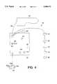
- FIG. 1is a front elevational view of the present invention
- FIG. 2is a top elevational view of the apparatus of FIG. 1,
- FIG. 3is a cross-sectional view taken along the line 3-3 of FIG. 2,
- FIG. 4is a schematic diagram of the control circuit of the apparatus of FIG. 1,
- FIG. 5is an enlarged elevational view, in cross-section, of the hand held portable image capture unit of the present invention
- FIG. 6is an elevational view of the light delivery assembly of FIG. passageway from a fiber sleeve
- FIG. 7is a top view of the light delivery system of FIG. 6,
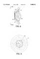
- FIG. 8is an enlarged elevational view, in cross-section, of the ends of the fanned out fiber optics about the cornea contact lens
- FIG. 9is a cross-sectional view taken along the line 9--9 of FIG. 8,
- FIG. 10is an enlarged elevational view, in cross-section, illustrating another embodiment providing dual concentric light passageways about the cornea contact lens
- FIG. 11is a view taken along the line 11--11 of FIG. 10,
- FIG. 12is an optical layout of the various lenses in the portable capture unit of the present invention.
- FIG. 13is an elevational view, in cross-section, illustrating the removal of the objective head of the capture unit along with the lens system and the substitution of a Goldman type lens thereon, and
- FIG. 14is a cross-sectional view of the connecting cable between the housing and the hand held unit of the present invention.
- the reference numeral 10generally indicates the eye imaging system of the present invention and generally includes a hand held portable image capture unit 12, a suitable housing are console 14 and a connecting cable 16.
- the housing 14generally includes an electrical power source 18, a light source 20, a slide light filter 22, a keyboard 24, a viewing monitor 26, an output recorder such as a printer 28, a still video recorder such as a digital laser floppy disk 32, and/or a VHS recorder 30, a control panel 19, a charge coupled device control 21, and foot pedal control 23.
- the foot pedal control 23includes light intensity control 27a, focus control 29a and capture control 31a thereby allowing the operator to control the operation of the apparatus 10 while holding the capture unit 12 by hands.
- the keyboard 24is a white balance intensity control for insuring true color representation by the charge coupled device.
- the control 21receives digital images from the capture unit 12 and converts them to an analog output for transmission to the recorder 30, the printer 28, the VHS 30, and monitor 26.
- the portable image capture unit 12is shown connected to the cable 16 which includes, as best seen in FIG. 14 a quartz fiber optic cable 40, a power cable 54 and a remote control cable 56.
- the portable image capture unit 12also includes an imaging and focusing optics 36 (FIGS. 5 and 12), and a digital imaging device 38 which is a charged coupled image device such as a 0.5 charged couple device (CCD), which electronically captures the image for transmission to the CCD controller 21.
- the imaging and focusing opticsincludes, as best seen in FIGS.
- a primary cornea contact lens 42which is a dual lens, a primary lens 44, a condensing lens 46, a reducing lens 48, collectively known as the primary lens system, an iris diaphragm 50 and an insertable lens 52 (FIG. 5).
- the primary lens systemis releasably connected to the unit 12 by set screws (not shown) and may be removed as will be more fully discussed hereinafter.
- the iris diaphragm 50may be set at a suitable F/Stop setting to control the depth of field for optimal visualization and imaging of the features of interest.
- the insertable lens 52effectively controls the field of view imaged on the CCD 38 and can be changed to provide a varied view of the posterior chamber of the human eye varying from a 15° view to a 150° span.
- Focus motor 41actuates the focus of the optics 36.
- the CCD 38is a chromatic image device for obtaining color images of the posterior chamber which provides a true color representation of the posterior chamber and any pathology present and by using different wave lengths of light views different layers of the posterior chamber.
- color imagingenables the unit 10 to provide stereo imaging and makes it easier to determine if a pathology is active or calcified.
- a lens systemmust be added to the imaging and focusing optics 36 to prevent color aberration. That is, the colors of red, green and blue will normally separate and will create a hazy image if the color aberration is not corrected.
- a first triplet lens 60is provided in the imaging and focusing optics (FIGS.
- each of the triplets 60 and 62include three lenses for acting on the different wave lengths of the colors of red, green and blue thereby preventing any color aberrations and maintaining true color representation.
- the chromatic CCD 38may also be used for monochromatic imaging.
- a concentric light passagewayis provided surrounding the cornea contact lens 42 for illuminating the eye through the cornea. That is, a continuous 360° light source is provided which gives an even distribution of light to the posterior chamber of the eye and also has the advantage of requiring a lower light intensity.
- the quartz fiber optic cable 40is connected to a bundle 70 of sleeve fiber optic fibers in which the individual fibers 72 are fanned outwardly and the ends 74 are positioned to form a continuous 360° light source around the cornea lens 42 in which the ends 74 provide a concentric light passageway surrounding the cornea contact lens 42 for providing a light source directed through the cornea.
- the outer ends 76 of the fanned out fiber optic fibers 72converge towards the axis of the cornea contact lens 42 for giving a larger field of view.
- the ID of the concentric light passage formed by the ends 76may be 7.5 mm and have a thickness of 0.016 mm and converges at an angle of 10° relative to the access of the lens 42, and include approximately 2,000 fibers.
- various other angles of incidentmay be provided to the cornea for compensating for various cornea shapes.
- the concentric light passagewayprovides a lower incident of reflection from the cornea, and light is distributed at a low intensity and at a uniform spread out distribution.
- the concentric light passagewayincludes two concentric light passages wherein like parts to that shown in FIGS. 8 and 9 are similarly numbered with the addition of the suffix
- a second concentric passagewayis formed by ends 78 of the fanned out fibers 72a which further increases the distribution of light to the posterior chamber.
- the ends 78 of the second concentric passagewayconverges towards the axis of the cornea contact lens at a different angle from the ends 76a and for example only, may converge at an angle of 30° .
- Another advantage of the multiple concentric like passagewaysis the ability to allow the unit 10 to accommodate abnormal cornea shapes such as the difference between pediatric and geriatric patients.
- the portable capture unit 12is shown with the primary lens system removed and a Goldman type lens 80 has been attached thereto which contains its own mirror which allows close angle imaging in the interior chamber such as for tumor detection. Or if desired, the primary lens system may be removed and the hand held portable capture unit 12 may be used for external imaging of the eye. Further, if desired a fiber optic cable port (not shown) may be provided for communication with the cable 40 for providing transclera illumination to the exterior of the eye which provides indirect illumination. This is useful in the adult eye that has cataracts or dilates poorly.
- the CCD 38is advantageous over conventional 35 mm cameras as it requires less light and therefore less illumination of the interior of the eye.
- the use of the concentric light passage sources of FIGS. 5-9provide lower light point intensity as the light is distributed in low intensity and spread out.
- the light source 20is preferably a tungsten lamp which provides a continuous soft light as compared to incandescent lights or a flash or strobe.
- the side light filter 22may be slid in place over the lamp 20 and filtered light is sent out over the connecting cable 16 and the fiber optic cable 40.
- Various types of filtersmay be used such as yellow T, orange, red, fluorescein, or green.
- the operatormay select the spectral composition of the illumination for either black and white or color imaging, red free viewing and imaging of the fundus, or deep blue stimulation of Fluorescein for imaging and angiography.
- the output image signal from the capture unit 12is transmitted over the connecting cable 16 and digitally displayed in the monitor 26 thereby allowing the operator to insure that the best view is obtained.
- the digital signalmay be copied to long term digital storage on the computer floppy diskette 32 for later reference and/or computer manipulation or may be printed out on a color digital printer 28 for hard copy file documentation.
- the imager 10can provide stored image for stereo imaging of structures of clinical interest in the eye.
- the present invention 10is particularly advantageous as the hand held portable capture unit is particularly useful for bedridden patients or babies in incubators. Furthermore, the output from the CCD 38 is immediately shown on the monitor 26 and therefore good images can be preserved without trial and error. In addition, the digital output may be recorded, printed out, compared side-by-side, reworked, and less storage is required.
- the present eye imaging systemcan record retinal images in either color or monochromatic mode using a 15° to 150° degree of view, and a portable hand held system allows super wide angle retinal documentation extending to 150° .
- the present inventioncan store images in a time and space saving fashion while allowing telephone transfer of full color images via a modem anywhere in the world in a few seconds.
- the present low white light systemrequires no flash to record an image. This is a great advantage especially when concerned with photophobic patients or the fear of phytotoxicity.
- this inventionaffords the recording of continuous VHS tape of any view that is captured by the capture unit be it color, monochromatic or fluorescein angiography. This greatly enhances teaching capabilities to both the medical and patient population.
- the viewing monitor 26may be Model CT-1382-VY sold by Panasonic.
- the output recorder 28may be Model UP5200MD sold by Sony.
- the VCR 30may be Model AG-2520SQPB sold by Panasonic.
- the floppy recorder 32may be Model AG810 sold by Panasonic.
- the CCD 38may be Model LX-450A sold by Optronics.
Landscapes
- Life Sciences & Earth Sciences (AREA)
- Health & Medical Sciences (AREA)
- Surgery (AREA)
- Biophysics (AREA)
- Ophthalmology & Optometry (AREA)
- Engineering & Computer Science (AREA)
- Biomedical Technology (AREA)
- Heart & Thoracic Surgery (AREA)
- Medical Informatics (AREA)
- Molecular Biology (AREA)
- Physics & Mathematics (AREA)
- Animal Behavior & Ethology (AREA)
- General Health & Medical Sciences (AREA)
- Public Health (AREA)
- Veterinary Medicine (AREA)
- Eye Examination Apparatus (AREA)
- Eyeglasses (AREA)
- Studio Devices (AREA)
- Magnetic Resonance Imaging Apparatus (AREA)
- Apparatus For Radiation Diagnosis (AREA)
- Image Input (AREA)
Abstract
Description
Claims (8)
Priority Applications (15)
| Application Number | Priority Date | Filing Date | Title |
|---|---|---|---|
| US08/340,976US5608472A (en) | 1992-11-06 | 1994-11-17 | Eye imaging system |
| NZ296848ANZ296848A (en) | 1994-11-17 | 1995-11-14 | Eye imaging system including hand held image capture unit with fibre optic to transmit light to eye |
| KR1019970703379AKR100359011B1 (en) | 1994-11-17 | 1995-11-14 | Visual Imaging System |
| JP51694996AJP4097692B2 (en) | 1994-11-17 | 1995-11-14 | Eyeball image forming system |
| ES95939933TES2229243T3 (en) | 1994-11-17 | 1995-11-14 | SYSTEM TO OBTAIN IMAGES FROM ONE EYE. |
| PCT/US1995/014753WO1996015712A1 (en) | 1994-11-17 | 1995-11-14 | Eye imaging system |
| EP95939933AEP0790799B1 (en) | 1994-11-17 | 1995-11-14 | Eye imaging system |
| CA002206888ACA2206888C (en) | 1994-11-17 | 1995-11-14 | Eye imaging system |
| AU41575/96AAU701821B2 (en) | 1994-11-17 | 1995-11-14 | Eye imaging system |
| DE69533518TDE69533518T2 (en) | 1994-11-17 | 1995-11-14 | ARRANGEMENT FOR ILLUSTRATING THE EYE |
| AT95939933TATE275864T1 (en) | 1994-11-17 | 1995-11-14 | ARRANGEMENT FOR IMAGING THE INSIDE OF THE EYE |
| RU97110126/14ARU2159572C2 (en) | 1994-11-17 | 1995-11-14 | System for building eye image |
| CN95196931ACN1170343A (en) | 1994-11-17 | 1995-11-14 | eye imaging system |
| ZA959705AZA959705B (en) | 1994-11-17 | 1995-11-15 | Eye imaging system |
| IL11600595AIL116005A (en) | 1994-11-17 | 1995-11-15 | Eye imaging system |
Applications Claiming Priority (2)
| Application Number | Priority Date | Filing Date | Title |
|---|---|---|---|
| US97270492A | 1992-11-06 | 1992-11-06 | |
| US08/340,976US5608472A (en) | 1992-11-06 | 1994-11-17 | Eye imaging system |
Related Parent Applications (1)
| Application Number | Title | Priority Date | Filing Date |
|---|---|---|---|
| US97270492AContinuation-In-Part | 1992-11-06 | 1992-11-06 |
Publications (1)
| Publication Number | Publication Date |
|---|---|
| US5608472Atrue US5608472A (en) | 1997-03-04 |
Family
ID=23335726
Family Applications (1)
| Application Number | Title | Priority Date | Filing Date |
|---|---|---|---|
| US08/340,976Expired - LifetimeUS5608472A (en) | 1992-11-06 | 1994-11-17 | Eye imaging system |
Country Status (15)
| Country | Link |
|---|---|
| US (1) | US5608472A (en) |
| EP (1) | EP0790799B1 (en) |
| JP (1) | JP4097692B2 (en) |
| KR (1) | KR100359011B1 (en) |
| CN (1) | CN1170343A (en) |
| AT (1) | ATE275864T1 (en) |
| AU (1) | AU701821B2 (en) |
| CA (1) | CA2206888C (en) |
| DE (1) | DE69533518T2 (en) |
| ES (1) | ES2229243T3 (en) |
| IL (1) | IL116005A (en) |
| NZ (1) | NZ296848A (en) |
| RU (1) | RU2159572C2 (en) |
| WO (1) | WO1996015712A1 (en) |
| ZA (1) | ZA959705B (en) |
Cited By (56)
| Publication number | Priority date | Publication date | Assignee | Title |
|---|---|---|---|---|
| US5903333A (en)* | 1997-06-24 | 1999-05-11 | Neuroptics, Inc. | Contact lens for use with ophthalmic monitoring systems |
| US5953097A (en)* | 1997-06-24 | 1999-09-14 | Neuroptics, Inc. | Contact lens for use with ophthalmic monitoring systems |
| US6419671B1 (en)* | 1999-12-23 | 2002-07-16 | Visx, Incorporated | Optical feedback system for vision correction |
| US20030103191A1 (en)* | 2001-11-06 | 2003-06-05 | Ocular Instruments, Inc. | Wide angle lens for use with a scanning laser ophthalmoscope |
| US20030208125A1 (en)* | 2002-04-09 | 2003-11-06 | Rodney Dennis Watkins | Fundus Camera |
| US20040004695A1 (en)* | 2002-04-19 | 2004-01-08 | Yuichi Sugino | Ophthalmologic photographing apparatus |
| US20040036840A1 (en)* | 2001-03-21 | 2004-02-26 | Marino Joseph A | Apparatus and method for testing visual acuity and fixation control |
| EP1417925A1 (en)* | 2002-11-07 | 2004-05-12 | Haag-Streit Ag | Apparatus for viewing an eye |
| US20050157260A1 (en)* | 2003-11-12 | 2005-07-21 | Graham Raymond D. | Lens for producing stereoscopic images |
| US20060181678A1 (en)* | 1999-04-23 | 2006-08-17 | Neuroptics, Inc. A California Corporation | Pupilometer with pupil irregularity detection, pupil tracking, and pupil response detection capability, glaucoma screening capability, intracranial pressure detection capability, and ocular aberration measurement capability |
| US20070036397A1 (en)* | 2005-01-26 | 2007-02-15 | Honeywell International Inc. | A distance iris recognition |
| US20070063049A1 (en)* | 2004-07-09 | 2007-03-22 | Anson Gary S | Portable data reading device with integrated web server for configuration and data extraction |
| US20070140531A1 (en)* | 2005-01-26 | 2007-06-21 | Honeywell International Inc. | standoff iris recognition system |
| US20070189582A1 (en)* | 2005-01-26 | 2007-08-16 | Honeywell International Inc. | Approaches and apparatus for eye detection in a digital image |
| US20070211924A1 (en)* | 2006-03-03 | 2007-09-13 | Honeywell International Inc. | Invariant radial iris segmentation |
| US20070276853A1 (en)* | 2005-01-26 | 2007-11-29 | Honeywell International Inc. | Indexing and database search system |
| US20070274570A1 (en)* | 2005-01-26 | 2007-11-29 | Honeywell International Inc. | Iris recognition system having image quality metrics |
| US20070274571A1 (en)* | 2005-01-26 | 2007-11-29 | Honeywell International Inc. | Expedient encoding system |
| US20080075441A1 (en)* | 2006-03-03 | 2008-03-27 | Honeywell International Inc. | Single lens splitter camera |
| US20080123052A1 (en)* | 2006-11-29 | 2008-05-29 | Clarity Medical Systems, Inc. | Delivering a short Arc lamp light for eye imaging |
| US20080267456A1 (en)* | 2007-04-25 | 2008-10-30 | Honeywell International Inc. | Biometric data collection system |
| US20080309876A1 (en)* | 2007-06-15 | 2008-12-18 | Massie Norbert A | Method And Apparatus For Imaging An Eye Of A Small Animal |
| US20100033677A1 (en)* | 2008-08-08 | 2010-02-11 | Honeywell International Inc. | Image acquisition system |
| US20100118270A1 (en)* | 2008-11-06 | 2010-05-13 | Clarity Medical Systems, Inc. | Adaptor for mounting a gonio lens onto a hand-held eye examination device |
| US20100182440A1 (en)* | 2008-05-09 | 2010-07-22 | Honeywell International Inc. | Heterogeneous video capturing system |
| EP2345362A1 (en)* | 2010-01-18 | 2011-07-20 | Dieter Mann GmbH | Fundus camera |
| US20110187845A1 (en)* | 2006-03-03 | 2011-08-04 | Honeywell International Inc. | System for iris detection, tracking and recognition at a distance |
| US20110228224A1 (en)* | 2008-11-28 | 2011-09-22 | Kamran Siminou | Methods, systems, and devices for monitoring anisocoria and asymmetry of pupillary reaction to stimulus |
| US8049812B2 (en) | 2006-03-03 | 2011-11-01 | Honeywell International Inc. | Camera with auto focus capability |
| US8085993B2 (en) | 2006-03-03 | 2011-12-27 | Honeywell International Inc. | Modular biometrics collection system architecture |
| US8213782B2 (en) | 2008-08-07 | 2012-07-03 | Honeywell International Inc. | Predictive autofocusing system |
| US8280119B2 (en) | 2008-12-05 | 2012-10-02 | Honeywell International Inc. | Iris recognition system using quality metrics |
| US8472681B2 (en) | 2009-06-15 | 2013-06-25 | Honeywell International Inc. | Iris and ocular recognition system using trace transforms |
| US8630464B2 (en) | 2009-06-15 | 2014-01-14 | Honeywell International Inc. | Adaptive iris matching using database indexing |
| US8705808B2 (en) | 2003-09-05 | 2014-04-22 | Honeywell International Inc. | Combined face and iris recognition system |
| US8742887B2 (en) | 2010-09-03 | 2014-06-03 | Honeywell International Inc. | Biometric visitor check system |
| US20140320819A1 (en)* | 2013-04-30 | 2014-10-30 | Avedro, Inc | Systems and methods for delivering light in eye treatments |
| US8911085B2 (en) | 2007-09-14 | 2014-12-16 | Neuroptics, Inc. | Pupilary screening system and method |
| US9155466B2 (en) | 2012-03-17 | 2015-10-13 | Visunex Medical Systems Co. Ltd. | Eye imaging apparatus with a wide field of view and related methods |
| US9179840B2 (en) | 2012-03-17 | 2015-11-10 | Visunex Medical Systems Co. Ltd. | Imaging and lighting optics of a contact eye camera |
| US20150342458A1 (en)* | 2014-05-30 | 2015-12-03 | Canon Kabushiki Kaisha | Ophthalmic apparatus |
| US20160287072A1 (en)* | 2010-12-13 | 2016-10-06 | University Of Virginia Patent Foundation | Intuitive techniques and apparatus for ophthalmic imaging |
| US9655517B2 (en) | 2012-02-02 | 2017-05-23 | Visunex Medical Systems Co. Ltd. | Portable eye imaging apparatus |
| US9848773B2 (en) | 2015-01-26 | 2017-12-26 | Visunex Medical Systems Co. Ltd. | Disposable cap for an eye imaging apparatus and related methods |
| US9872618B2 (en) | 2015-08-05 | 2018-01-23 | Phoenix Technology Group | Wide-field retinal imaging system |
| US9986908B2 (en) | 2014-06-23 | 2018-06-05 | Visunex Medical Systems Co. Ltd. | Mechanical features of an eye imaging apparatus |
| US10016178B2 (en) | 2012-02-02 | 2018-07-10 | Visunex Medical Systems Co. Ltd. | Eye imaging apparatus and systems |
| US10028657B2 (en) | 2015-05-22 | 2018-07-24 | Avedro, Inc. | Systems and methods for monitoring cross-linking activity for corneal treatments |
| US10114205B2 (en) | 2014-11-13 | 2018-10-30 | Avedro, Inc. | Multipass virtually imaged phased array etalon |
| US10137239B2 (en) | 2011-06-02 | 2018-11-27 | Avedro, Inc. | Systems and methods for monitoring time based photo active agent delivery or photo active marker presence |
| US10258809B2 (en) | 2015-04-24 | 2019-04-16 | Avedro, Inc. | Systems and methods for photoactivating a photosensitizer applied to an eye |
| US10350111B2 (en) | 2014-10-27 | 2019-07-16 | Avedro, Inc. | Systems and methods for cross-linking treatments of an eye |
| US10631726B2 (en) | 2017-01-11 | 2020-04-28 | Avedro, Inc. | Systems and methods for determining cross-linking distribution in a cornea and/or structural characteristics of a cornea |
| US11179576B2 (en) | 2010-03-19 | 2021-11-23 | Avedro, Inc. | Systems and methods for applying and monitoring eye therapy |
| US11207410B2 (en) | 2015-07-21 | 2021-12-28 | Avedro, Inc. | Systems and methods for treatments of an eye with a photosensitizer |
| US12171630B2 (en) | 2020-05-14 | 2024-12-24 | Thad Pierce Johnston | Dental evacuation tip with mount for dental mouth mirror |
Families Citing this family (13)
| Publication number | Priority date | Publication date | Assignee | Title |
|---|---|---|---|---|
| US5822036A (en)* | 1996-07-24 | 1998-10-13 | Research Development Foundation | Eye imaging unit having a circular light guide |
| US6215957B1 (en)* | 1999-12-03 | 2001-04-10 | Peter Arthur Van Houten | Synchronizer for fundus camera |
| US20120016349A1 (en) | 2001-01-29 | 2012-01-19 | Amo Development, Llc. | Hybrid ophthalmic interface apparatus and method of interfacing a surgical laser with an eye |
| US20080071254A1 (en)* | 2001-01-29 | 2008-03-20 | Advanced Medical Optics, Inc. | Ophthalmic interface apparatus and system and method of interfacing a surgical laser with an eye |
| RU2258452C2 (en)* | 2003-09-03 | 2005-08-20 | Федеральное государственное унитарное предприятие "Государственный научный центр "Научно-исследовательский институт органических полупродуктов и красителей" (ФГУП "ГНЦ "НИОПИК") | Method and device for diagnostics and photodynamic therapy of eye disease |
| RU2291662C2 (en)* | 2004-12-02 | 2007-01-20 | Андрей Борисович Фролов | Device for registering color image of human eye's front part (versions) |
| CN101474061B (en)* | 2008-01-03 | 2011-07-20 | 北京宏仁凝瑞科技发展有限公司 | Contact type eyeground imaging system |
| WO2011094678A1 (en)* | 2010-02-01 | 2011-08-04 | Lensar, Inc. | Purkinjie image-based alignment of suction ring in ophthalmic applications |
| RU2454166C2 (en)* | 2010-06-30 | 2012-06-27 | Общество с ограниченной ответственностью "АКСИОМА-10" (ООО" АКСИОМА-10") | Device of interactive assessment of visual, perceptive and cognitive abilities of person |
| CN101972136A (en)* | 2010-11-23 | 2011-02-16 | 上海新眼光光电技术有限公司 | Retina digital imaging adapter |
| ES2531189B2 (en)* | 2013-08-05 | 2015-12-18 | Universidad De Alicante | Procedure for quantification of ocular opacity of an intraocular lens |
| CN105662332A (en)* | 2016-04-13 | 2016-06-15 | 南京航空航天大学 | Wide-angle eye ground retina imaging device and method for annular illumination |
| CN107115096B (en)* | 2017-05-02 | 2019-01-08 | 北京东方新月科技发展有限公司 | Eyeground optical imaging system |
Citations (4)
| Publication number | Priority date | Publication date | Assignee | Title |
|---|---|---|---|---|
| US3944341A (en)* | 1972-09-25 | 1976-03-16 | Retina Foundation | Wide-angle ophthalmoscope and fundus camera |
| US4200362A (en)* | 1972-09-25 | 1980-04-29 | Retina Foundation | Ophthalmoscope with uniform illumination |
| US4715703A (en)* | 1982-10-12 | 1987-12-29 | Rodenstock Instrument Corporation | Ocular-fundus analyzer |
| US5125730A (en)* | 1990-06-29 | 1992-06-30 | The United States Of America As Represented By The Administrator Of The National Aeronautics And Space Administration | Portable dynamic fundus instrument |
Family Cites Families (5)
| Publication number | Priority date | Publication date | Assignee | Title |
|---|---|---|---|---|
| US1816420A (en)* | 1924-05-13 | 1931-07-28 | Bernard Ulmann Co Inc | Skein winding machine |
| US3894787A (en)* | 1969-05-19 | 1975-07-15 | Battelle Development Corp | Holograms |
| US5347989A (en)* | 1992-09-11 | 1994-09-20 | Welch Allyn, Inc. | Control mechanism for steerable elongated probe having a sealed joystick |
| TW286275B (en)* | 1992-11-06 | 1996-09-21 | Res Dev Foundation | |
| JPH07236613A (en)* | 1994-03-01 | 1995-09-12 | Tomey:Kk | Eye ball observing device |
- 1994
- 1994-11-17USUS08/340,976patent/US5608472A/ennot_activeExpired - Lifetime
- 1995
- 1995-11-14ESES95939933Tpatent/ES2229243T3/ennot_activeExpired - Lifetime
- 1995-11-14JPJP51694996Apatent/JP4097692B2/ennot_activeExpired - Lifetime
- 1995-11-14CACA002206888Apatent/CA2206888C/ennot_activeExpired - Lifetime
- 1995-11-14KRKR1019970703379Apatent/KR100359011B1/ennot_activeExpired - Lifetime
- 1995-11-14ATAT95939933Tpatent/ATE275864T1/ennot_activeIP Right Cessation
- 1995-11-14NZNZ296848Apatent/NZ296848A/ennot_activeIP Right Cessation
- 1995-11-14EPEP95939933Apatent/EP0790799B1/ennot_activeExpired - Lifetime
- 1995-11-14RURU97110126/14Apatent/RU2159572C2/enactive
- 1995-11-14AUAU41575/96Apatent/AU701821B2/ennot_activeExpired
- 1995-11-14CNCN95196931Apatent/CN1170343A/enactivePending
- 1995-11-14WOPCT/US1995/014753patent/WO1996015712A1/enactiveIP Right Grant
- 1995-11-14DEDE69533518Tpatent/DE69533518T2/ennot_activeExpired - Lifetime
- 1995-11-15ZAZA959705Apatent/ZA959705B/enunknown
- 1995-11-15ILIL11600595Apatent/IL116005A/ennot_activeIP Right Cessation
Patent Citations (4)
| Publication number | Priority date | Publication date | Assignee | Title |
|---|---|---|---|---|
| US3944341A (en)* | 1972-09-25 | 1976-03-16 | Retina Foundation | Wide-angle ophthalmoscope and fundus camera |
| US4200362A (en)* | 1972-09-25 | 1980-04-29 | Retina Foundation | Ophthalmoscope with uniform illumination |
| US4715703A (en)* | 1982-10-12 | 1987-12-29 | Rodenstock Instrument Corporation | Ocular-fundus analyzer |
| US5125730A (en)* | 1990-06-29 | 1992-06-30 | The United States Of America As Represented By The Administrator Of The National Aeronautics And Space Administration | Portable dynamic fundus instrument |
Cited By (99)
| Publication number | Priority date | Publication date | Assignee | Title |
|---|---|---|---|---|
| US5953097A (en)* | 1997-06-24 | 1999-09-14 | Neuroptics, Inc. | Contact lens for use with ophthalmic monitoring systems |
| US5903333A (en)* | 1997-06-24 | 1999-05-11 | Neuroptics, Inc. | Contact lens for use with ophthalmic monitoring systems |
| US20100195049A1 (en)* | 1999-04-23 | 2010-08-05 | Neuroptics, Inc. | Pupilometer with pupil irregularity detection, pupil tracking, and pupil response detection capability, glaucoma screening capability, intracranial pressure detection capability, and ocular aberration measurement capability |
| US20060181678A1 (en)* | 1999-04-23 | 2006-08-17 | Neuroptics, Inc. A California Corporation | Pupilometer with pupil irregularity detection, pupil tracking, and pupil response detection capability, glaucoma screening capability, intracranial pressure detection capability, and ocular aberration measurement capability |
| US8235526B2 (en) | 1999-04-23 | 2012-08-07 | Neuroptics, Inc. | Pupilometer with pupil irregularity detection, pupil tracking, and pupil response detection capability, glaucoma screening capability, intracranial pressure detection capability, and ocular aberration measurement capability |
| US7670002B2 (en) | 1999-04-23 | 2010-03-02 | Neuroptics, Inc. | Pupilometer with pupil irregularity detection, pupil tracking, and pupil response detection capability, glaucoma screening capability, intracranial pressure detection capability, and ocular aberration measurement capability |
| US6419671B1 (en)* | 1999-12-23 | 2002-07-16 | Visx, Incorporated | Optical feedback system for vision correction |
| US6793654B2 (en) | 1999-12-23 | 2004-09-21 | Visx, Inc. | Optical feedback system for vision correction |
| US20040036840A1 (en)* | 2001-03-21 | 2004-02-26 | Marino Joseph A | Apparatus and method for testing visual acuity and fixation control |
| US20080143961A1 (en)* | 2001-03-21 | 2008-06-19 | Marino Joseph A | Apparatus and method for testing visual acuity and fixation control |
| US20070064197A1 (en)* | 2001-03-21 | 2007-03-22 | Marino Joseph A | Apparatus and method for testing visual acuity and fixation control |
| US20030103191A1 (en)* | 2001-11-06 | 2003-06-05 | Ocular Instruments, Inc. | Wide angle lens for use with a scanning laser ophthalmoscope |
| US20030208125A1 (en)* | 2002-04-09 | 2003-11-06 | Rodney Dennis Watkins | Fundus Camera |
| US20040004695A1 (en)* | 2002-04-19 | 2004-01-08 | Yuichi Sugino | Ophthalmologic photographing apparatus |
| US20040135971A1 (en)* | 2002-11-07 | 2004-07-15 | Haag-Streit Ag | Device for viewing an eye |
| EP1417925A1 (en)* | 2002-11-07 | 2004-05-12 | Haag-Streit Ag | Apparatus for viewing an eye |
| US8705808B2 (en) | 2003-09-05 | 2014-04-22 | Honeywell International Inc. | Combined face and iris recognition system |
| US20050157260A1 (en)* | 2003-11-12 | 2005-07-21 | Graham Raymond D. | Lens for producing stereoscopic images |
| US20070063049A1 (en)* | 2004-07-09 | 2007-03-22 | Anson Gary S | Portable data reading device with integrated web server for configuration and data extraction |
| US8098901B2 (en) | 2005-01-26 | 2012-01-17 | Honeywell International Inc. | Standoff iris recognition system |
| US8050463B2 (en) | 2005-01-26 | 2011-11-01 | Honeywell International Inc. | Iris recognition system having image quality metrics |
| US8045764B2 (en) | 2005-01-26 | 2011-10-25 | Honeywell International Inc. | Expedient encoding system |
| US8090157B2 (en) | 2005-01-26 | 2012-01-03 | Honeywell International Inc. | Approaches and apparatus for eye detection in a digital image |
| US20070140531A1 (en)* | 2005-01-26 | 2007-06-21 | Honeywell International Inc. | standoff iris recognition system |
| US20070036397A1 (en)* | 2005-01-26 | 2007-02-15 | Honeywell International Inc. | A distance iris recognition |
| US20070274571A1 (en)* | 2005-01-26 | 2007-11-29 | Honeywell International Inc. | Expedient encoding system |
| US20070276853A1 (en)* | 2005-01-26 | 2007-11-29 | Honeywell International Inc. | Indexing and database search system |
| US20070274570A1 (en)* | 2005-01-26 | 2007-11-29 | Honeywell International Inc. | Iris recognition system having image quality metrics |
| US20100002913A1 (en)* | 2005-01-26 | 2010-01-07 | Honeywell International Inc. | distance iris recognition |
| US7593550B2 (en) | 2005-01-26 | 2009-09-22 | Honeywell International Inc. | Distance iris recognition |
| US20070189582A1 (en)* | 2005-01-26 | 2007-08-16 | Honeywell International Inc. | Approaches and apparatus for eye detection in a digital image |
| US8488846B2 (en) | 2005-01-26 | 2013-07-16 | Honeywell International Inc. | Expedient encoding system |
| US7761453B2 (en) | 2005-01-26 | 2010-07-20 | Honeywell International Inc. | Method and system for indexing and searching an iris image database |
| US8285005B2 (en) | 2005-01-26 | 2012-10-09 | Honeywell International Inc. | Distance iris recognition |
| US8442276B2 (en) | 2006-03-03 | 2013-05-14 | Honeywell International Inc. | Invariant radial iris segmentation |
| US7933507B2 (en) | 2006-03-03 | 2011-04-26 | Honeywell International Inc. | Single lens splitter camera |
| US8064647B2 (en) | 2006-03-03 | 2011-11-22 | Honeywell International Inc. | System for iris detection tracking and recognition at a distance |
| US20110187845A1 (en)* | 2006-03-03 | 2011-08-04 | Honeywell International Inc. | System for iris detection, tracking and recognition at a distance |
| US8761458B2 (en) | 2006-03-03 | 2014-06-24 | Honeywell International Inc. | System for iris detection, tracking and recognition at a distance |
| US20080075441A1 (en)* | 2006-03-03 | 2008-03-27 | Honeywell International Inc. | Single lens splitter camera |
| US8049812B2 (en) | 2006-03-03 | 2011-11-01 | Honeywell International Inc. | Camera with auto focus capability |
| US20070211924A1 (en)* | 2006-03-03 | 2007-09-13 | Honeywell International Inc. | Invariant radial iris segmentation |
| US8085993B2 (en) | 2006-03-03 | 2011-12-27 | Honeywell International Inc. | Modular biometrics collection system architecture |
| US7621638B2 (en) | 2006-11-29 | 2009-11-24 | Clarity Medical Systems, Inc. | Delivering a short Arc lamp light for eye imaging |
| US20080123052A1 (en)* | 2006-11-29 | 2008-05-29 | Clarity Medical Systems, Inc. | Delivering a short Arc lamp light for eye imaging |
| US20080267456A1 (en)* | 2007-04-25 | 2008-10-30 | Honeywell International Inc. | Biometric data collection system |
| US8063889B2 (en) | 2007-04-25 | 2011-11-22 | Honeywell International Inc. | Biometric data collection system |
| US20080309876A1 (en)* | 2007-06-15 | 2008-12-18 | Massie Norbert A | Method And Apparatus For Imaging An Eye Of A Small Animal |
| US7993000B2 (en) | 2007-06-15 | 2011-08-09 | Phoenix Research Laboratories | Method and apparatus for imaging an eye of a small animal |
| US8911085B2 (en) | 2007-09-14 | 2014-12-16 | Neuroptics, Inc. | Pupilary screening system and method |
| US8436907B2 (en) | 2008-05-09 | 2013-05-07 | Honeywell International Inc. | Heterogeneous video capturing system |
| US20100182440A1 (en)* | 2008-05-09 | 2010-07-22 | Honeywell International Inc. | Heterogeneous video capturing system |
| US8213782B2 (en) | 2008-08-07 | 2012-07-03 | Honeywell International Inc. | Predictive autofocusing system |
| US8090246B2 (en) | 2008-08-08 | 2012-01-03 | Honeywell International Inc. | Image acquisition system |
| US20100033677A1 (en)* | 2008-08-08 | 2010-02-11 | Honeywell International Inc. | Image acquisition system |
| US20100118270A1 (en)* | 2008-11-06 | 2010-05-13 | Clarity Medical Systems, Inc. | Adaptor for mounting a gonio lens onto a hand-held eye examination device |
| US20110228224A1 (en)* | 2008-11-28 | 2011-09-22 | Kamran Siminou | Methods, systems, and devices for monitoring anisocoria and asymmetry of pupillary reaction to stimulus |
| US8534840B2 (en) | 2008-11-28 | 2013-09-17 | Neuroptics, Inc. | Methods, systems, and devices for monitoring anisocoria and asymmetry of pupillary reaction to stimulus |
| US8280119B2 (en) | 2008-12-05 | 2012-10-02 | Honeywell International Inc. | Iris recognition system using quality metrics |
| US8472681B2 (en) | 2009-06-15 | 2013-06-25 | Honeywell International Inc. | Iris and ocular recognition system using trace transforms |
| US8630464B2 (en) | 2009-06-15 | 2014-01-14 | Honeywell International Inc. | Adaptive iris matching using database indexing |
| EP2345362A1 (en)* | 2010-01-18 | 2011-07-20 | Dieter Mann GmbH | Fundus camera |
| US20110176109A1 (en)* | 2010-01-18 | 2011-07-21 | Dieter Mann Gmbh | Fundus Camera |
| US8353595B2 (en) | 2010-01-18 | 2013-01-15 | Dieter Mann Gmbh | Fundus camera |
| US11179576B2 (en) | 2010-03-19 | 2021-11-23 | Avedro, Inc. | Systems and methods for applying and monitoring eye therapy |
| US8742887B2 (en) | 2010-09-03 | 2014-06-03 | Honeywell International Inc. | Biometric visitor check system |
| US9986910B2 (en)* | 2010-12-13 | 2018-06-05 | University Of Virginia Patent Foundation | Intuitive techniques and apparatus for ophthalmic imaging |
| US20160287072A1 (en)* | 2010-12-13 | 2016-10-06 | University Of Virginia Patent Foundation | Intuitive techniques and apparatus for ophthalmic imaging |
| US10137239B2 (en) | 2011-06-02 | 2018-11-27 | Avedro, Inc. | Systems and methods for monitoring time based photo active agent delivery or photo active marker presence |
| US10258309B2 (en) | 2012-02-02 | 2019-04-16 | Visunex Medical Systems Co., Ltd. | Eye imaging apparatus and systems |
| US9655517B2 (en) | 2012-02-02 | 2017-05-23 | Visunex Medical Systems Co. Ltd. | Portable eye imaging apparatus |
| US10016178B2 (en) | 2012-02-02 | 2018-07-10 | Visunex Medical Systems Co. Ltd. | Eye imaging apparatus and systems |
| US9179840B2 (en) | 2012-03-17 | 2015-11-10 | Visunex Medical Systems Co. Ltd. | Imaging and lighting optics of a contact eye camera |
| US9351639B2 (en) | 2012-03-17 | 2016-05-31 | Visunex Medical Systems Co. Ltd. | Eye imaging apparatus with a wide field of view and related methods |
| US9155466B2 (en) | 2012-03-17 | 2015-10-13 | Visunex Medical Systems Co. Ltd. | Eye imaging apparatus with a wide field of view and related methods |
| US9907467B2 (en) | 2012-03-17 | 2018-03-06 | Visunex Medical Systems Co. Ltd. | Eye imaging apparatus with a wide field of view and related methods |
| US9907468B2 (en) | 2012-03-17 | 2018-03-06 | Visunex Medical Systems Co. Ltd. | Eye imaging apparatus with sequential illumination |
| EP2975998A4 (en)* | 2013-03-17 | 2016-11-16 | Visunex Medical Systems Co Ltd | OCULAR IMAGING APPARATUS HAVING A BROAD FIELD OF VISION AND ASSOCIATED METHODS |
| US20140320819A1 (en)* | 2013-04-30 | 2014-10-30 | Avedro, Inc | Systems and methods for delivering light in eye treatments |
| US20150342458A1 (en)* | 2014-05-30 | 2015-12-03 | Canon Kabushiki Kaisha | Ophthalmic apparatus |
| US9986908B2 (en) | 2014-06-23 | 2018-06-05 | Visunex Medical Systems Co. Ltd. | Mechanical features of an eye imaging apparatus |
| US10350111B2 (en) | 2014-10-27 | 2019-07-16 | Avedro, Inc. | Systems and methods for cross-linking treatments of an eye |
| US12427062B2 (en) | 2014-10-27 | 2025-09-30 | Avedro, Inc. | Systems and methods for cross-linking treatments of an eye |
| US11219553B2 (en) | 2014-10-27 | 2022-01-11 | Avedro, Inc. | Systems and methods for cross-linking treatments of an eye |
| US10114205B2 (en) | 2014-11-13 | 2018-10-30 | Avedro, Inc. | Multipass virtually imaged phased array etalon |
| US9848773B2 (en) | 2015-01-26 | 2017-12-26 | Visunex Medical Systems Co. Ltd. | Disposable cap for an eye imaging apparatus and related methods |
| US10258809B2 (en) | 2015-04-24 | 2019-04-16 | Avedro, Inc. | Systems and methods for photoactivating a photosensitizer applied to an eye |
| US12070618B2 (en) | 2015-04-24 | 2024-08-27 | Avedro, Inc. | Systems and methods for photoactivating a photosensitizer applied to an eye |
| US11167149B2 (en) | 2015-04-24 | 2021-11-09 | Avedro, Inc. | Systems and methods for photoactivating a photosensitizer applied to an eye |
| US10028657B2 (en) | 2015-05-22 | 2018-07-24 | Avedro, Inc. | Systems and methods for monitoring cross-linking activity for corneal treatments |
| US12214039B2 (en) | 2015-07-21 | 2025-02-04 | Advero, Inc. | Systems and methods for treatments of an eye with a photosensitizer |
| US11207410B2 (en) | 2015-07-21 | 2021-12-28 | Avedro, Inc. | Systems and methods for treatments of an eye with a photosensitizer |
| US10893803B2 (en) | 2015-08-05 | 2021-01-19 | Phoenix Technology Group Llc | Wide-field retinal imaging system |
| US10244943B2 (en) | 2015-08-05 | 2019-04-02 | Phoenix Technology Group | Wide-field retinal imaging system |
| US9872618B2 (en) | 2015-08-05 | 2018-01-23 | Phoenix Technology Group | Wide-field retinal imaging system |
| US11529050B2 (en) | 2017-01-11 | 2022-12-20 | Avedro, Inc. | Systems and methods for determining cross-linking distribution in a cornea and/or structural characteristics of a cornea |
| US12004811B2 (en) | 2017-01-11 | 2024-06-11 | Avedro, Inc. | Systems and methods for determining cross-linking distribution in a cornea and/or structural characteristics of a cornea |
| US10631726B2 (en) | 2017-01-11 | 2020-04-28 | Avedro, Inc. | Systems and methods for determining cross-linking distribution in a cornea and/or structural characteristics of a cornea |
| US12171630B2 (en) | 2020-05-14 | 2024-12-24 | Thad Pierce Johnston | Dental evacuation tip with mount for dental mouth mirror |
Also Published As
| Publication number | Publication date |
|---|---|
| JPH10509078A (en) | 1998-09-08 |
| JP4097692B2 (en) | 2008-06-11 |
| ATE275864T1 (en) | 2004-10-15 |
| KR970706756A (en) | 1997-12-01 |
| IL116005A0 (en) | 1996-01-31 |
| AU701821B2 (en) | 1999-02-04 |
| WO1996015712A1 (en) | 1996-05-30 |
| EP0790799A1 (en) | 1997-08-27 |
| CN1170343A (en) | 1998-01-14 |
| KR100359011B1 (en) | 2003-01-24 |
| RU2159572C2 (en) | 2000-11-27 |
| CA2206888A1 (en) | 1996-05-30 |
| NZ296848A (en) | 1998-10-28 |
| EP0790799B1 (en) | 2004-09-15 |
| DE69533518D1 (en) | 2004-10-21 |
| AU4157596A (en) | 1996-06-17 |
| IL116005A (en) | 2003-02-12 |
| CA2206888C (en) | 2009-01-06 |
| DE69533518T2 (en) | 2005-08-18 |
| ES2229243T3 (en) | 2005-04-16 |
| EP0790799A4 (en) | 1999-02-03 |
| ZA959705B (en) | 1997-05-15 |
Similar Documents
| Publication | Publication Date | Title |
|---|---|---|
| US5608472A (en) | Eye imaging system | |
| US11813024B2 (en) | Hand-held portable fundus camera for screening photography | |
| US4717952A (en) | Medical television system | |
| US5239984A (en) | Hand-held opto-diagnostic instrument system | |
| EP1292212B1 (en) | Digital eye camera | |
| US6685317B2 (en) | Digital eye camera | |
| US5662586A (en) | Hand held diagnostic instrument with video imaging | |
| US20030208125A1 (en) | Fundus Camera | |
| US6729727B2 (en) | Ophthalmic photographing apparatus | |
| WO1994010900A1 (en) | Eye imaging system | |
| US5914770A (en) | Ophthalmological examination instrument and method for operation thereof | |
| US10512398B2 (en) | Portable retinography device | |
| JP3404638B2 (en) | Goggles for eye surface measurement and eye surface measurement device | |
| US7258440B2 (en) | Ophthalmic photographic apparatus | |
| JPS6258252B2 (en) | ||
| JPS61288825A (en) | Eyeground camera used in common to mydriasis and non-mydriasis | |
| KENNEDY et al. | Impact of video on endourology | |
| JP3408839B2 (en) | Ophthalmic imaging equipment | |
| JPH02115981A (en) | Image filing system | |
| JPH05203881A (en) | Image system for stereoscopy and image integration system for stereoscopy | |
| HK1081421B (en) | Imaging apparatus and adaptors therefor | |
| HK1081421A1 (en) | Imaging apparatus and adaptors therefor | |
| Fox | Photographic Technique | |
| AU2003203548A1 (en) | Improved Fundus Camera | |
| JPH02165114A (en) | Endoscope |
Legal Events
| Date | Code | Title | Description |
|---|---|---|---|
| AS | Assignment | Owner name:RESEARCH DEVELOPMENT FOUNDATION, NEVADA Free format text:ASSIGNMENT OF ASSIGNORS INTEREST;ASSIGNORS:MURPHEE, ALAN LINN;LUSTY, STEVEN EUGENE;BURRIS, JAMES A.;REEL/FRAME:007255/0908;SIGNING DATES FROM 19941103 TO 19941110 | |
| AS | Assignment | Owner name:RESEARCH DEVELOPMENT FOUNDATION Free format text:ASSIGNMENT OF ASSIGNORS INTEREST;ASSIGNOR:SZIRTH, BERNARD C.;REEL/FRAME:007406/0005 Effective date:19950302 | |
| STCF | Information on status: patent grant | Free format text:PATENTED CASE | |
| FEPP | Fee payment procedure | Free format text:PAYOR NUMBER ASSIGNED (ORIGINAL EVENT CODE: ASPN); ENTITY STATUS OF PATENT OWNER: SMALL ENTITY | |
| FPAY | Fee payment | Year of fee payment:4 | |
| CC | Certificate of correction | ||
| FPAY | Fee payment | Year of fee payment:8 | |
| FPAY | Fee payment | Year of fee payment:12 | |
| REMI | Maintenance fee reminder mailed | ||
| AS | Assignment | Owner name:PINTO INVESTMENT PARTNERS, L.P., TEXAS Free format text:SECURITY AGREEMENT;ASSIGNORS:CLARITY MEDICAL SYSTEMS, INC.;RETCAM, INC.;REEL/FRAME:023364/0475 Effective date:20061107 | |
| AS | Assignment | Owner name:CLARITY MEDICAL SYSTEMS, INC., CALIFORNIA Free format text:RELEASE BY SECURED PARTY;ASSIGNOR:PINTO INVESTMENT PARTNERS, L.P.;REEL/FRAME:030390/0733 Effective date:20130509 Owner name:RETCAM, INC., CALIFORNIA Free format text:RELEASE BY SECURED PARTY;ASSIGNOR:PINTO INVESTMENT PARTNERS, L.P.;REEL/FRAME:030390/0733 Effective date:20130509 | |
| AS | Assignment | Owner name:COMERICA BANK, A TEXAS BANKING ASSOCIATION, MICHIG Free format text:SECURITY AGREEMENT;ASSIGNOR:CLARITY MEDICAL SYSTEMS, INC.;REEL/FRAME:031156/0796 Effective date:20130509 | |
| AS | Assignment | Owner name:CLARITY MEDICAL SYSTEMS, INC., CALIFORNIA Free format text:RELEASE BY SECURED PARTY;ASSIGNOR:COMERICA BANK;REEL/FRAME:043271/0930 Effective date:20170810 |