US5608413A - Frequency-selective antenna with different signal polarizations - Google Patents
Frequency-selective antenna with different signal polarizationsDownload PDFInfo
- Publication number
- US5608413A US5608413AUS08/483,360US48336095AUS5608413AUS 5608413 AUS5608413 AUS 5608413AUS 48336095 AUS48336095 AUS 48336095AUS 5608413 AUS5608413 AUS 5608413A
- Authority
- US
- United States
- Prior art keywords
- antenna
- signal
- transmission line
- segment
- slot
- Prior art date
- Legal status (The legal status is an assumption and is not a legal conclusion. Google has not performed a legal analysis and makes no representation as to the accuracy of the status listed.)
- Expired - Lifetime
Links
Images


Classifications
- H—ELECTRICITY
- H01—ELECTRIC ELEMENTS
- H01Q—ANTENNAS, i.e. RADIO AERIALS
- H01Q21/00—Antenna arrays or systems
- H01Q21/30—Combinations of separate antenna units operating in different wavebands and connected to a common feeder system
- H—ELECTRICITY
- H01—ELECTRIC ELEMENTS
- H01Q—ANTENNAS, i.e. RADIO AERIALS
- H01Q1/00—Details of, or arrangements associated with, antennas
- H01Q1/12—Supports; Mounting means
- H01Q1/22—Supports; Mounting means by structural association with other equipment or articles
- H01Q1/24—Supports; Mounting means by structural association with other equipment or articles with receiving set
- H01Q1/241—Supports; Mounting means by structural association with other equipment or articles with receiving set used in mobile communications, e.g. GSM
- H01Q1/242—Supports; Mounting means by structural association with other equipment or articles with receiving set used in mobile communications, e.g. GSM specially adapted for hand-held use
- H01Q1/243—Supports; Mounting means by structural association with other equipment or articles with receiving set used in mobile communications, e.g. GSM specially adapted for hand-held use with built-in antennas
- H—ELECTRICITY
- H01—ELECTRIC ELEMENTS
- H01Q—ANTENNAS, i.e. RADIO AERIALS
- H01Q5/00—Arrangements for simultaneous operation of antennas on two or more different wavebands, e.g. dual-band or multi-band arrangements
- H01Q5/40—Imbricated or interleaved structures; Combined or electromagnetically coupled arrangements, e.g. comprising two or more non-connected fed radiating elements
Definitions
- the present inventionrelates generally to antennas and more particularly, to antennas which are responsive to different frequencies and polarizations.
- polarizationrefers to the direction and behavior of the electric field vector in an electromagnetic signal which is radiating through free space (i.e., empty space with no electrons, ions or other objects which distort the radiation).
- free spacei.e., empty space with no electrons, ions or other objects which distort the radiation.
- the electric field vectorssinusoidally reverse their direction in a plane which is orthogonal to the radiation path but they do not rotate. If the orientation of the vectors is vertical, the signal is said to have vertical polarization; if the orientation is horizontal, the signal is said to be have horizontal polarization.
- Elliptical polarizationmay be either right-handed or left-handed.
- right-handed polarizationthe vector direction rotates clockwise as seen from the radiative element which radiated the signal.
- the vector directionrotates counter-clockwise in left-handed polarization.
- Antennas which are designed to receive signals which have one of these elliptical polarizationswill typically tend to reject signals which have the other polarization (e.g., in an antenna which is designed to receive right-handed polarization, the gain of a signal with left-handed polarization will be significantly reduced from the gain of a signal with right-handed polarization).
- Various communication systemsrequire the transmission and reception of signals with different frequencies and polarizations.
- cellular telephone systemshave conventionally divided large service areas into smaller cells which each have a terrestrial transmitter.
- different hand-held wireless telephonescommunicate through the cell's transmitter on a terrestrial (cellular) frequency with linear polarization.
- satellitesare combined with ground-based "gateways" such as a telephone exchange or a private dispatcher to facilitate communication between widely-spaced mobile users.
- gatewaysdifferent hand-held wireless telephones communicate on an extra-terrestrial (satellite) frequency with circular polarization.
- a cellular telephonewhich is intended for both terrestrial and extra-terrestrial communication preferably responds to a linearly-polarized signal having a first frequency with significant azimuthal gain and responds to a circularly-polarized signal having a second frequency with significant elevational gain.
- a conventional antenna structure for such a cellular telephonehas two antennas which are connected by a diplexer.
- Each leg of the diplexeris intended for passing a different one of the frequencies and includes, therefore, a filter network which has a significant insertion loss at the other of the frequencies.
- this structurecan respond to the terrestrial and extra-terrestrial signals, its additional filter networks add size and cost to cellular telephones which inherently have limited space and which are directed at a cost-conscious consumer.
- Quadrafilar helical antennascan also be designed to respond to linearly-polarized and elliptically-polarized signals.
- An exemplary QHAhas four input terminals which must each be fed with different, predetermined phase relationships to obtain the different polarizations.
- this antenna structurecan also respond to linearly-polarized and circularly-polarized signals, a diplexer is required to realize the necessary phasing.
- QHA gainis typically directed azimuthally which detracts from the usefulness of QHA structures in satellite communications.
- the present inventionis directed to a dual-frequency antenna which can respond to signals with different frequencies and polarizations and which is suitable for inexpensive, high-volume manufacturing.
- a stripline circuitwhich is adapted to define a slot radiator and a patch radiator that are coupled to a single transmission line.
- Ground planes of the stripline circuitdefine slot radiative elements and a pair of coupling apertures.
- the slot radiative elementsform the slot radiator and a patch radiative member is spaced from the apertures to form the patch radiator.
- the transmission lineis arranged to pass between the midpoints of the slot radiators to generate linearly-polarized radiation at a first signal wavelength ⁇ 1 and is arranged to excite the apertures in quadrature, i.e., with a 90° phase difference, to generate elliptically-polarized radiation from the patch radiative element at a second wavelength ⁇ 2 .
- the slot radiative elementsare preferably dimensioned to be resonant at a wavelength ⁇ 1 and the patch radiative element is preferably dimensioned to be resonant at a wavelength of ⁇ 2 .
- the stripline circuitincludes a flexible, dielectric substrate which can be mounted to a handheld, wireless telephone.
- the flexible substrateserves as a hinge to permit the antenna to be pivoted from a stowed position to different operational positions which cause the linearly-polarized radiation to be radiated azimuthally and the elliptically-polarized radiation to be radiated elevationally.
- the transmission lineincludes line segments which can be adjusted to present large impedances to the patch radiator and the slot radiator at their respective resonant wavelengths to enhance the amplitude of their excitation signals.
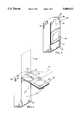
- FIG. 1is a perspective view of a frequency-selective antenna in accordance with the present invention, the antenna is illustrated in a stowed position on a handheld, wireless telephone;
- FIG. 2is a perspective view of the frequency-selective antenna of FIG. 1 in the process of rotation to vertical and horizontal operating positions;
- FIG. 3Ais a side elevation view of the frequency-selective antenna of FIG. 2 in its vertical operating position combined with a polar radiation pattern that is obtained with a first signal frequency;
- FIG. 3Bis a top plan view of the polar radiation pattern and frequency-selective antenna of FIG. 3A;
- FIG. 4Ais a side elevation view of the frequency-selective antenna of FIG. 2 in its horizontal operating position combined with a polar radiation pattern that is obtained with a second signal frequency;
- FIG. 4Bis a top plan view of the polar radiation pattern and frequency-selective antenna of FIG. 4A;
- FIG. 5is a top plan view of the frequency-selective antenna of FIG. 2 when it is in its horizontal operating position;
- FIG. 6is a side elevation view of the frequency-selective antenna of FIG. 5;
- FIG. 7is a bottom plan view of the frequency-selective antenna of FIG. 5;
- FIG. 8is a view similar to FIG. 5, in which a patch radiative element and its substrate have been removed for clarity of illustration;
- FIG. 9is a view of the structure within the line 9 of FIG. 6, which shows another transmission line embodiment.
- FIG. 10is a view similar to FIG. 5, which illustrates another frequency-selective antenna embodiment.
- FIG. 1illustrates a hand-held, wireless telephone 20 which includes a dual-frequency antenna 30.
- the antenna 30is pivotably mounted to the upper edge 32 of a side 33 of the telephone 20.
- FIG. 1shows the antenna in a stowed position 34 in which it abuts the telephone side 33.
- FIG. 2illustrates that the antenna 30 can be rotated (as indicated by rotation arrow 35) to a horizontal operational position 36 and a vertical operational position 38.
- the antenna 30includes a slot radiator 40 and a patch radiator 42.
- the slot radiator 40responds to a radio-frequency (rf) signal having a first wavelength ⁇ 1 by radiating a linearly-polarized electromagnetic signal with a relative gain which is shown in the polar radiation pattern 46 of FIGS. 3A and 3B.
- the linearly-polarized signalhas significant gain in all azimuthal directions.
- the patch radiator 42responds to an rf signal having a second wavelength ⁇ 2 by radiating an elliptically-polarized electromagnetic signal with a relative gain which is shown in the polar radiation pattern 48 of FIGS. 4A and 4B.
- the elliptically-polarized signalhas significant gain in the elevation direction.
- the antenna 30includes a flexible substrate whose upper edge 49 is connected to the upper edge 32 of the telephone 20. This connection facilitates rotation of the antenna 30 between its stowed position 34 and its operating positions 36 and 38.
- FIGS. 5-9show that the antenna 30 includes a lower ground plane 50, an upper ground plane 52 and a radiative patch 54.
- the ground planes 50 and 52are spaced apart by a dielectric substrate 56 and the radiative patch 54 is spaced from the upper ground plane 52 by another dielectric substrate 58.
- a transmission line 60is positioned between the lower ground plane 50 and the upper ground plane 52.
- the ground planes 50 and 52, the patch radiative element 54 and the transmission line 60are formed from conductive sheets, e.g., copper.
- the dielectric substrates 56 and 58are formed of dielectrics which preferably have low relative permittivities (.di-elect cons. r ) and low loss tangents (tan ⁇ ) at the first and second operating frequencies.
- the lower ground plane 50is configured to define a slot radiative element 62 and the upper ground plane 52 is configured to define a slot radiative element 64 which is aligned with the slot radiative element 62 in the lower ground plane.
- the upper ground plane 52also defines a pair of apertures 66 and 68 which are positioned beneath the patch radiative element 54.
- the transmission line 60is configured to communicate between the telephone 20 and its antenna 30.
- the transmission line 60has a first end 70 which is positioned within the telephone 20 and a second end 71 which is positioned in the antenna 30. Between its ends 70 and 71, the transmission line 60 follows a path which passes between the first and second slot radiative elements 62 and 64 and which also passes beneath the first and second apertures 66 and 68.
- the substrate 56terminates in the upper edge 49 which adjoins the upper edge 32 of the telephone's side 33.
- the substrate 56is formed of a flexible dielectric so that the edge 49 effectively forms a hinge which permits the antenna 30 to be swung between the stowed position 34 of FIG. 1 and the operational positions 36 and 38 of FIG. 2, e.g., as indicated by broken-line interim antenna positions 80 and 82 in FIG. 6.
- the arrangement of the transmission line 60 between the lower ground plane 50 and the upper ground plane 52belongs to a conventional microwave structural type which is typically referred to as "stripline".
- the substrate 56sets the spacing between the ground planes 50 and 52 and positions the transmission line 60 (in an exemplary fabrication method, the substrate 56 is formed of two layers which are bonded on each side of the transmission line 60).
- a stripline circuitis adapted to define the slot radiator 40 and the patch radiator 42.
- the spaced ground planes 50 and 52 and their slot radiative elements 62 and 64form the slot radiator 40 which is directed to the radiation of signals that have a wavelength of ⁇ 1 .
- the slot radiative elements 62 and 64are dimensioned to be resonant at a wavelength of ⁇ 1 , e.g., the width 91 (shown in FIG. 5) of the slot radiative elements is selected to be ⁇ 1 /2.
- slot radiative elementsare the inverse equivalent of metal dipole radiative elements, i.e., one is formed from the other by reversing their conductive and dielectric parts. Therefore, if the transmission line 60 is arranged to feed the slot radiative elements 62 and 64 at the middle of their length 91, they radiate a linearly-polarized electromagnetic signal whose polarization is parallel with the elements' length 91 as indicated by the broken-line arrow 92 in FIG. 5. The signal coupling is enhanced if the transmission line 60 and the slot radiative elements 62 and 64 are orthogonally arranged in the region where they intersect.
- the patch radiative element 54 and the first and second apertures 66 and 68 of the ground plane 52form the patch radiator 42 which is directed to the radiation of signals which have a wavelength of ⁇ 2 .
- the radiative element 54is dimensioned to be resonant at a wavelength of ⁇ 2 , e.g., its transverse dimensions 95 and 96 (shown in FIG. 5) are selected to be ⁇ 2 /2.
- the apertures 66 and 68couple signals between the transmission line 60 and the patch radiative element 54.
- the apertures 66 and 68couple respectively to transmission line segments 98 and 99 which lie directly beneath them.
- Signals which are coupled from the line segment 98cause the patch radiative element 54 to emit a linearly-polarized radiation.
- the direction of this polarizationis parallel with the path of the line segment 98 as indicated by the broken-line arrow 100 in FIG. 5.
- Signals which are coupled from the line segment 99also cause the patch radiative element 54 to emit a linearly-polarized radiation.
- the direction of this latter polarizationis parallel with the path of the line segment 99 as indicated by the broken-line arrow 101 in FIG. 5.
- the distance along the transmission line 60 between the line segments 98 and 99is preferably ⁇ 2 /4, i.e., the apertures 66 and 68 are excited in quadrature.
- the signal coupling and radiationare enhanced if the transmission line segments 98 and 99 are orthogonal and they are each orthogonally arranged with their respective aperture.
- the radiation from the patch radiator 42will have circular polarization because the apertures 66 and 68 are similar and their arrangements with their transmission line segments 98 and 99 are also similar.
- the antenna 30When it is desired to operate the telephone 20, the antenna 30 is mechanically pivoted from its stowed position 34 of FIG. 1 to either of its operational positions 36 and 38 of FIG. 2.
- a signalis then fed into the end 70 of the transmission line 60 from a transceiver which is positioned within the telephone 20. If the signal has a wavelength of ⁇ 1 , it excites the slot radiator 40 which is resonant at this wavelength. Therefore, radiation at a wavelength of ⁇ 1 is directed away from each of the slot radiative elements 62 and 64 as indicated in the polar radiation pattern 46 of FIGS. 3A and 3B.
- the antenna 30includes only one patch radiator 42 (in contrast with an array of radiators), the beam width of the radiation from each of the antenna 30 will be very broad, e.g., on the order of 100°. Therefore, although the radiation gain will have a maximum in a direction which is orthogonal to the ground planes 50 and 52, there will be significant radiation gain in all azimuthal directions as indicated in FIG. 3B.
- the signal from the telephone 20has a wavelength of ⁇ 2 , it excites the patch radiator 42 which is resonant at this wavelength. Therefore, radiation at a wavelength of ⁇ 2 is directed orthogonally away from the patch radiative element 54 as indicated in the polar radiation pattern 48 of FIGS. 4A and 4B. Because the antenna 30 includes only one patch radiator 42 (in contrast with an array of radiators), the radiation beam width will again be very broad. The gain will have a maximum in a direction that is orthogonal to the plane of the patch radiative element 54, i.e. the radiation is directed primarily in the elevation direction.
- the transmission line 60includes a segment 110 which connects the segment 99 and a load impedance at the line end 71.
- the segment 110When the patch radiator 42 is being excited by a signal of wavelength ⁇ 2 , the segment 110 preferably presents a large impedance to the segment 99 (and aperture 68) to enhance the signal magnitude on the segment 99. This is accomplished by arranging the load impedance at the end 71 to be an open circuit (as shown in FIG. 6) and by forming the length of the segment 110, e.g., ⁇ 2 /2, to set a predetermined impedance. As is well known in the stripline art, a length ⁇ 2 /2 of transmission line will transform the open circuit at the end 71 to an open circuit at the line segment 99.
- the load impedance at the end 71can be arranged to be a short circuit by connecting it to one or both of the ground planes 50 and 52 as shown in FIG. 9.
- the length of the segment 110is then set to be approximately ⁇ 2 /4.
- this length of transmission linewill transform the short circuit at the end 71 to an open circuit at the line segment 99.
- the slot radiative elements 62 and 64When the patch radiator 42 is being excited by a signal of wavelength ⁇ 2 , the slot radiative elements 62 and 64 will appear to be either capacitive (if ⁇ 2 is greater than ⁇ 1 ) or inductive (if ⁇ 2 is less than ⁇ 1 ).
- the effect of this inductive or capacitive reactance upon the patch radiator 42can be reduced by reducing the width of the slot radiative elements 62 and 64 (the dimension orthogonal to the length 91) and by increasing the difference between the wavelengths ⁇ 1 and ⁇ 2 .
- the slot widthcan be set to the 0.01 ⁇ 1 and the operating frequencies selected to be 1200 MHz and 900 MHz which cause ⁇ 2 to be approximately 1/3 greater than ⁇ 1 .
- the transmission line 60includes a segment 112 which is directly between the slot radiative elements 62 and 64.
- the line 60also includes a segment 114 which connects the segments 112 and 98.
- the segment 114When the slot radiator 40 is being excited by a signal of wavelength ⁇ 1 , the segment 114 preferably presents a large impedance to segment 112 to enhance the signal magnitude that is generated across the slot radiative elements 62 and 64.
- the patch radiator 42will have a specific impedance to signals with a wavelength of ⁇ 1 .
- this specific impedancecan be transformed into the same or a larger impedance by a proper selection of the length of the transmission line segment 114, i.e., set to ⁇ 1 /n wherein n is chosen to present a predetermined impedance at a signal wavelength of ⁇ 1 to the segment 112.
- the lengths of the line segments 110 and 114can be selected to enhance the signal radiation from the slot radiator 40 and the patch radiator 42.
- antenna 30can be formed without the lower ground plane 50, it is preferably included to decrease signal loss from the transmission line 60 and to enhance the azimuthal radiation of signal the slot radiative element 64 by addition of the second radiative element 62.
- the teachings of the inventioncan be extended to an antenna 120 which is shown in FIG. 10.
- the antenna 120is similar to the antenna 30 of FIG. 5 but the positions of the slot radiator 40 and the patch radiator 42 have been interchanged and the transmission line 60 is replaced by a transmission line 122 which is arranged to couple to each of the radiators.
- a proper selection of the lengths of line segments in the transmission line 120can be made to enhance the radiation from each of the radiators when they are excited by their respective signals.
- the dielectric substrates 56 and 58 of the antennas 30 and 120are preferably formed from dielectrics, e.g., duroid, which have low relative permittivities (.di-elect cons. r ) and low loss tangents (tan ⁇ ) at microwave operating frequencies.
- the dielectric substrate 56is preferably selected from dielectrics such as polyimide (e.g., as manufactured under the trademark Kapton by E. I. du Pont de Nemours & Company) which are flexible and which can be flexed a large number of times without failure.
- the coupling apertures 66 and 68are not intended to be resonant at a wavelength of ⁇ 2 but need only be large enough to insure that sufficient energy is coupled between the transmission line 60 and the radiative patch element 54. Accordingly, the aperture dimensions are generally much less than ⁇ 2 /2.
- the coupling apertures 66 and 68are shown to be slot-shaped in the antennas 30 and 120, other well-known coupling shapes, e.g., the circular apertures 126 and 128 shown in broken lines in FIG. 5, can be employed in other antenna embodiments.
- Antennas in accordance with the inventionare responsive to terrestrial and extra-terrestrial signals that have different radiation polarizations. Because they can be formed from simple, conventional stripline structures with conventional photolithographic techniques, these antennas are suitable for inexpensive, high-volume fabrication.
- antennashave the property of reciprocity, i.e., the characteristics of a given antenna are the same whether it is transmitting or receiving.
- the use of terms such as radiative element and radiation in the description and claimsare for convenience and clarity of illustration and are not intended to limit structures taught by the invention.
- An antenna which can generate dual-frequency radiationcan inherently receive the same dual-frequency radiation.
Landscapes
- Physics & Mathematics (AREA)
- Electromagnetism (AREA)
- Engineering & Computer Science (AREA)
- Computer Networks & Wireless Communication (AREA)
- Waveguide Aerials (AREA)
- Variable-Direction Aerials And Aerial Arrays (AREA)
Abstract
Description
1. Field of the Invention
The present invention relates generally to antennas and more particularly, to antennas which are responsive to different frequencies and polarizations.
2. Description of the Related Art
By definition, polarization refers to the direction and behavior of the electric field vector in an electromagnetic signal which is radiating through free space (i.e., empty space with no electrons, ions or other objects which distort the radiation). In signals with linear polarization, the electric field vectors sinusoidally reverse their direction in a plane which is orthogonal to the radiation path but they do not rotate. If the orientation of the vectors is vertical, the signal is said to have vertical polarization; if the orientation is horizontal, the signal is said to be have horizontal polarization.
In contrast, if the direction of the electric field vectors rotates at some constant angular velocity the signal has elliptical polarization. Signals with elliptical polarization can be effectively generated by combining two linearly polarized signals which are oriented in an orthogonal relationship and which have a predetermined phase difference between their electric field vectors. Circular polarization is a special case of elliptical polarization in which the two linearly polarized signals have electric field vectors of equal magnitude and a phase difference of 90°.
Elliptical polarization may be either right-handed or left-handed. In right-handed polarization, the vector direction rotates clockwise as seen from the radiative element which radiated the signal. The vector direction rotates counter-clockwise in left-handed polarization. Antennas which are designed to receive signals which have one of these elliptical polarizations will typically tend to reject signals which have the other polarization (e.g., in an antenna which is designed to receive right-handed polarization, the gain of a signal with left-handed polarization will be significantly reduced from the gain of a signal with right-handed polarization).
When an elliptically polarized signal is reflected from a conductive surface, its rotation is reversed. That is, if a transmitted signal with right-handed polarization strikes a reflecting surface, the reflected signal will have left-handed polarization. The reflected signal will be received with less gain than the transmitted signal by an antenna which is designed to receive right-handed polarization. Consequently, signals with elliptical polarization have an inherent resistance to multipath distortion; this is one reason why satellite communication is typically conducted with circularly-polarized signals.
Various communication systems require the transmission and reception of signals with different frequencies and polarizations. For example, cellular telephone systems have conventionally divided large service areas into smaller cells which each have a terrestrial transmitter. In a particular cell, different hand-held wireless telephones communicate through the cell's transmitter on a terrestrial (cellular) frequency with linear polarization. In a satellite-based system, satellites are combined with ground-based "gateways" such as a telephone exchange or a private dispatcher to facilitate communication between widely-spaced mobile users. To communicate through the gateways, different hand-held wireless telephones communicate on an extra-terrestrial (satellite) frequency with circular polarization.
Therefore, a cellular telephone which is intended for both terrestrial and extra-terrestrial communication preferably responds to a linearly-polarized signal having a first frequency with significant azimuthal gain and responds to a circularly-polarized signal having a second frequency with significant elevational gain.
A conventional antenna structure for such a cellular telephone has two antennas which are connected by a diplexer. Each leg of the diplexer is intended for passing a different one of the frequencies and includes, therefore, a filter network which has a significant insertion loss at the other of the frequencies. Although this structure can respond to the terrestrial and extra-terrestrial signals, its additional filter networks add size and cost to cellular telephones which inherently have limited space and which are directed at a cost-conscious consumer.
Quadrafilar helical antennas (QHA) can also be designed to respond to linearly-polarized and elliptically-polarized signals. An exemplary QHA has four input terminals which must each be fed with different, predetermined phase relationships to obtain the different polarizations. Although this antenna structure can also respond to linearly-polarized and circularly-polarized signals, a diplexer is required to realize the necessary phasing. In addition, QHA gain is typically directed azimuthally which detracts from the usefulness of QHA structures in satellite communications.
The present invention is directed to a dual-frequency antenna which can respond to signals with different frequencies and polarizations and which is suitable for inexpensive, high-volume manufacturing.
These goals are achieved with a stripline circuit which is adapted to define a slot radiator and a patch radiator that are coupled to a single transmission line. Ground planes of the stripline circuit define slot radiative elements and a pair of coupling apertures. The slot radiative elements form the slot radiator and a patch radiative member is spaced from the apertures to form the patch radiator.
The transmission line is arranged to pass between the midpoints of the slot radiators to generate linearly-polarized radiation at a first signal wavelength λ1 and is arranged to excite the apertures in quadrature, i.e., with a 90° phase difference, to generate elliptically-polarized radiation from the patch radiative element at a second wavelength λ2. The slot radiative elements are preferably dimensioned to be resonant at a wavelength λ1 and the patch radiative element is preferably dimensioned to be resonant at a wavelength of λ2.
The stripline circuit includes a flexible, dielectric substrate which can be mounted to a handheld, wireless telephone. The flexible substrate serves as a hinge to permit the antenna to be pivoted from a stowed position to different operational positions which cause the linearly-polarized radiation to be radiated azimuthally and the elliptically-polarized radiation to be radiated elevationally.
The transmission line includes line segments which can be adjusted to present large impedances to the patch radiator and the slot radiator at their respective resonant wavelengths to enhance the amplitude of their excitation signals.
The novel features of the invention are set forth with particularity in the appended claims. The invention will be best understood from the following description when read in conjunction with the accompanying drawings.
FIG. 1 is a perspective view of a frequency-selective antenna in accordance with the present invention, the antenna is illustrated in a stowed position on a handheld, wireless telephone;
FIG. 2 is a perspective view of the frequency-selective antenna of FIG. 1 in the process of rotation to vertical and horizontal operating positions;
FIG. 3A is a side elevation view of the frequency-selective antenna of FIG. 2 in its vertical operating position combined with a polar radiation pattern that is obtained with a first signal frequency;
FIG. 3B is a top plan view of the polar radiation pattern and frequency-selective antenna of FIG. 3A;
FIG. 4A is a side elevation view of the frequency-selective antenna of FIG. 2 in its horizontal operating position combined with a polar radiation pattern that is obtained with a second signal frequency;
FIG. 4B is a top plan view of the polar radiation pattern and frequency-selective antenna of FIG. 4A;
FIG. 5 is a top plan view of the frequency-selective antenna of FIG. 2 when it is in its horizontal operating position;
FIG. 6 is a side elevation view of the frequency-selective antenna of FIG. 5;
FIG. 7 is a bottom plan view of the frequency-selective antenna of FIG. 5;
FIG. 8 is a view similar to FIG. 5, in which a patch radiative element and its substrate have been removed for clarity of illustration;
FIG. 9 is a view of the structure within theline 9 of FIG. 6, which shows another transmission line embodiment; and
FIG. 10 is a view similar to FIG. 5, which illustrates another frequency-selective antenna embodiment.
FIG. 1 illustrates a hand-held,wireless telephone 20 which includes a dual-frequency antenna 30. Theantenna 30 is pivotably mounted to theupper edge 32 of aside 33 of thetelephone 20. FIG. 1 shows the antenna in a stowedposition 34 in which it abuts thetelephone side 33. FIG. 2 illustrates that theantenna 30 can be rotated (as indicated by rotation arrow 35) to a horizontaloperational position 36 and a vertical operational position 38.
Theantenna 30 includes aslot radiator 40 and apatch radiator 42. When theantenna 30 is in its vertical operational position 38, theslot radiator 40 responds to a radio-frequency (rf) signal having a first wavelength λ1 by radiating a linearly-polarized electromagnetic signal with a relative gain which is shown in thepolar radiation pattern 46 of FIGS. 3A and 3B. The linearly-polarized signal has significant gain in all azimuthal directions. When theantenna 30 is in its horizontaloperational position 36, thepatch radiator 42 responds to an rf signal having a second wavelength λ2 by radiating an elliptically-polarized electromagnetic signal with a relative gain which is shown in thepolar radiation pattern 48 of FIGS. 4A and 4B. The elliptically-polarized signal has significant gain in the elevation direction.
Theantenna 30 includes a flexible substrate whoseupper edge 49 is connected to theupper edge 32 of thetelephone 20. This connection facilitates rotation of theantenna 30 between its stowedposition 34 and itsoperating positions 36 and 38.
A description of the operation of theantenna 30 is enhanced if it is preceded by a detailed description of the antenna's structure. Accordingly, attention is first directed to FIGS. 5-9 which show that theantenna 30 includes alower ground plane 50, anupper ground plane 52 and aradiative patch 54. The ground planes 50 and 52 are spaced apart by adielectric substrate 56 and theradiative patch 54 is spaced from theupper ground plane 52 by anotherdielectric substrate 58. Atransmission line 60 is positioned between thelower ground plane 50 and theupper ground plane 52. The ground planes 50 and 52, the patchradiative element 54 and thetransmission line 60 are formed from conductive sheets, e.g., copper. Thedielectric substrates
Thelower ground plane 50 is configured to define a slot radiative element 62 and theupper ground plane 52 is configured to define a slotradiative element 64 which is aligned with the slot radiative element 62 in the lower ground plane. As especially shown in FIG. 8, theupper ground plane 52 also defines a pair ofapertures radiative element 54.
Thetransmission line 60 is configured to communicate between thetelephone 20 and itsantenna 30. In particular, thetransmission line 60 has afirst end 70 which is positioned within thetelephone 20 and asecond end 71 which is positioned in theantenna 30. Between its ends 70 and 71, thetransmission line 60 follows a path which passes between the first and second slotradiative elements 62 and 64 and which also passes beneath the first andsecond apertures
Thesubstrate 56 terminates in theupper edge 49 which adjoins theupper edge 32 of the telephone'sside 33. Thesubstrate 56 is formed of a flexible dielectric so that theedge 49 effectively forms a hinge which permits theantenna 30 to be swung between the stowedposition 34 of FIG. 1 and theoperational positions 36 and 38 of FIG. 2, e.g., as indicated by broken-line interim antenna positions 80 and 82 in FIG. 6.
The arrangement of thetransmission line 60 between thelower ground plane 50 and theupper ground plane 52 belongs to a conventional microwave structural type which is typically referred to as "stripline". In this particular stripline, thesubstrate 56 sets the spacing between the ground planes 50 and 52 and positions the transmission line 60 (in an exemplary fabrication method, thesubstrate 56 is formed of two layers which are bonded on each side of the transmission line 60). In effect, a stripline circuit is adapted to define theslot radiator 40 and thepatch radiator 42. The spaced ground planes 50 and 52 and their slotradiative elements 62 and 64 form theslot radiator 40 which is directed to the radiation of signals that have a wavelength of λ1. Accordingly, the slotradiative elements 62 and 64 are dimensioned to be resonant at a wavelength of λ1, e.g., the width 91 (shown in FIG. 5) of the slot radiative elements is selected to be λ1 /2.
Electrically, slot radiative elements are the inverse equivalent of metal dipole radiative elements, i.e., one is formed from the other by reversing their conductive and dielectric parts. Therefore, if thetransmission line 60 is arranged to feed the slotradiative elements 62 and 64 at the middle of theirlength 91, they radiate a linearly-polarized electromagnetic signal whose polarization is parallel with the elements'length 91 as indicated by the broken-line arrow 92 in FIG. 5. The signal coupling is enhanced if thetransmission line 60 and the slotradiative elements 62 and 64 are orthogonally arranged in the region where they intersect.
The patchradiative element 54 and the first andsecond apertures ground plane 52 form thepatch radiator 42 which is directed to the radiation of signals which have a wavelength of λ2. Accordingly, theradiative element 54 is dimensioned to be resonant at a wavelength of λ2, e.g., itstransverse dimensions 95 and 96 (shown in FIG. 5) are selected to be λ2 /2.
Theapertures transmission line 60 and the patchradiative element 54. In particular, theapertures transmission line segments line segment 98 cause the patchradiative element 54 to emit a linearly-polarized radiation. The direction of this polarization is parallel with the path of theline segment 98 as indicated by the broken-line arrow 100 in FIG. 5. Signals which are coupled from theline segment 99 also cause the patchradiative element 54 to emit a linearly-polarized radiation. The direction of this latter polarization is parallel with the path of theline segment 99 as indicated by the broken-line arrow 101 in FIG. 5.
If the two linearly-polarized radiations have a 90° difference in phase, they will combine to form an elliptically-polarized radiation. Accordingly, the distance along thetransmission line 60 between theline segments apertures transmission line segments patch radiator 42 will have circular polarization because theapertures transmission line segments
When it is desired to operate thetelephone 20, theantenna 30 is mechanically pivoted from its stowedposition 34 of FIG. 1 to either of itsoperational positions 36 and 38 of FIG. 2. In electrical operation of theantenna 30, a signal is then fed into theend 70 of thetransmission line 60 from a transceiver which is positioned within thetelephone 20. If the signal has a wavelength of λ1, it excites theslot radiator 40 which is resonant at this wavelength. Therefore, radiation at a wavelength of λ1 is directed away from each of the slotradiative elements 62 and 64 as indicated in thepolar radiation pattern 46 of FIGS. 3A and 3B. Because theantenna 30 includes only one patch radiator 42 (in contrast with an array of radiators), the beam width of the radiation from each of theantenna 30 will be very broad, e.g., on the order of 100°. Therefore, although the radiation gain will have a maximum in a direction which is orthogonal to the ground planes 50 and 52, there will be significant radiation gain in all azimuthal directions as indicated in FIG. 3B.
In contrast, if the signal from thetelephone 20 has a wavelength of λ2, it excites thepatch radiator 42 which is resonant at this wavelength. Therefore, radiation at a wavelength of λ2 is directed orthogonally away from the patchradiative element 54 as indicated in thepolar radiation pattern 48 of FIGS. 4A and 4B. Because theantenna 30 includes only one patch radiator 42 (in contrast with an array of radiators), the radiation beam width will again be very broad. The gain will have a maximum in a direction that is orthogonal to the plane of the patchradiative element 54, i.e. the radiation is directed primarily in the elevation direction.
As shown in FIG. 5 and 7, thetransmission line 60 includes asegment 110 which connects thesegment 99 and a load impedance at theline end 71. When thepatch radiator 42 is being excited by a signal of wavelength λ2, thesegment 110 preferably presents a large impedance to the segment 99 (and aperture 68) to enhance the signal magnitude on thesegment 99. This is accomplished by arranging the load impedance at theend 71 to be an open circuit (as shown in FIG. 6) and by forming the length of thesegment 110, e.g., λ2 /2, to set a predetermined impedance. As is well known in the stripline art, a length λ2 /2 of transmission line will transform the open circuit at theend 71 to an open circuit at theline segment 99.
Alternatively, the load impedance at theend 71 can be arranged to be a short circuit by connecting it to one or both of the ground planes 50 and 52 as shown in FIG. 9. In this arrangement, the length of thesegment 110 is then set to be approximately λ2 /4. As is well known in the stripline art, this length of transmission line will transform the short circuit at theend 71 to an open circuit at theline segment 99.
When thepatch radiator 42 is being excited by a signal of wavelength λ2, the slotradiative elements 62 and 64 will appear to be either capacitive (if λ2 is greater than λ1) or inductive (if λ2 is less than λ1). The effect of this inductive or capacitive reactance upon thepatch radiator 42 can be reduced by reducing the width of the slot radiative elements 62 and 64 (the dimension orthogonal to the length 91) and by increasing the difference between the wavelengths λ1 and λ2. For example, the slot width can be set to the 0.01λ1 and the operating frequencies selected to be 1200 MHz and 900 MHz which cause λ2 to be approximately 1/3 greater than λ1.
As shown in FIG. 5 and 7, thetransmission line 60 includes asegment 112 which is directly between the slotradiative elements 62 and 64. Theline 60 also includes asegment 114 which connects thesegments slot radiator 40 is being excited by a signal of wavelength λ1, thesegment 114 preferably presents a large impedance tosegment 112 to enhance the signal magnitude that is generated across the slotradiative elements 62 and 64. Thepatch radiator 42 will have a specific impedance to signals with a wavelength of λ1. As is well known in the stripline art, this specific impedance can be transformed into the same or a larger impedance by a proper selection of the length of thetransmission line segment 114, i.e., set to λ1 /n wherein n is chosen to present a predetermined impedance at a signal wavelength of λ1 to thesegment 112. Thus, the lengths of theline segments slot radiator 40 and thepatch radiator 42.
Although effective embodiments of theantenna 30 can be formed without thelower ground plane 50, it is preferably included to decrease signal loss from thetransmission line 60 and to enhance the azimuthal radiation of signal the slotradiative element 64 by addition of the second radiative element 62.
The teachings of the invention can be extended to anantenna 120 which is shown in FIG. 10. Theantenna 120 is similar to theantenna 30 of FIG. 5 but the positions of theslot radiator 40 and thepatch radiator 42 have been interchanged and thetransmission line 60 is replaced by atransmission line 122 which is arranged to couple to each of the radiators. As in theantenna 30 of FIGS. 1-9, a proper selection of the lengths of line segments in thetransmission line 120 can be made to enhance the radiation from each of the radiators when they are excited by their respective signals.
Thedielectric substrates antennas dielectric substrate 56 is preferably selected from dielectrics such as polyimide (e.g., as manufactured under the trademark Kapton by E. I. du Pont de Nemours & Company) which are flexible and which can be flexed a large number of times without failure.
The coupling apertures 66 and 68 are not intended to be resonant at a wavelength of λ2 but need only be large enough to insure that sufficient energy is coupled between thetransmission line 60 and theradiative patch element 54. Accordingly, the aperture dimensions are generally much less than λ2 /2. Although thecoupling apertures antennas circular apertures
Antennas in accordance with the invention are responsive to terrestrial and extra-terrestrial signals that have different radiation polarizations. Because they can be formed from simple, conventional stripline structures with conventional photolithographic techniques, these antennas are suitable for inexpensive, high-volume fabrication.
As is well known, antennas have the property of reciprocity, i.e., the characteristics of a given antenna are the same whether it is transmitting or receiving. The use of terms such as radiative element and radiation in the description and claims are for convenience and clarity of illustration and are not intended to limit structures taught by the invention. An antenna which can generate dual-frequency radiation can inherently receive the same dual-frequency radiation.
While several illustrative embodiments of the invention have been shown and described, numerous variations and alternate embodiments will occur to those skilled in the art. Such variations and alternate embodiments are contemplated, and can be made without departing from the spirit and scope of the invention as defined in the appended claims.
Claims (28)
1. A dual-frequency antenna for operation with first and second rf signals which respectively have λ1 and λ2 wavelengths, comprising:
a slot radiator configured to radiate said first rf signal with linear polarization;
a patch radiator configured to radiate said second rf signal with elliptical radiation; and
a transmission line configured to carry said first and second rf signals and arranged to couple said first rf signal to said slot radiator and to couple said second rf signal to said patch radiator;
wherein;
said slot radiator includes a ground plane configured to define a slot radiative element;
said transmission line is spaced from a first side of said ground plane; and
said slot radiative element is positioned to couple said first rf signal between said transmission line and free space.
2. The antenna of claim 1, wherein said slot radiator has a length which is substantially λ1 /2.
3. The antenna of claim 2, wherein said patch radiator includes:
a patch radiative element spaced from a second side of said ground plane; and
first and second apertures defined by said ground plane and positioned to couple said second rf signal between said transmission line and said patch radiative element.
4. The antenna of claim 3, wherein said patch radiative element has a width which is substantially λ2 /2.
5. The antenna of claim 3, wherein:
said transmission line has first and second segments;
said first and second apertures are respectively coupled to said first and second segments; and
said first and second segments are spaced apart on said transmission line by substantially λ2 /n wherein n is chosen to obtain a predetermined elliptical polarization.
6. The antenna of claim 5, wherein n substantially equals 4 to obtain circular polarization.
7. A dual-frequency atenna for operation with first and second rf signals which respectively have λ1 and λ2 wavelengths, comprising:
a slot radiator configured to radiate said first rf signal with linear polarization;
a patch radiator configured to radiate said second rf signal with elliptical radiation; and
a transmission line configured to carry said first and second rf signals and arranged to coupled said first rf signal to said slot radiator and to couple said second rf signal to said patch radiator;
wherein said patch radiator includes:
a ground plane configured to define first and second aperatures; and
a patch radiative element spaced from a first side of said ground plane;
and wherein said transmission line is spaced from a second side of said ground plane; and
said first and second aperatures are positioned to coupled said second rf signal between said transmission line and said patch radiative element.
8. The atenna of claim 7 wherein said patch radiative element has a length which is substantially λ2 /2.
9. The antenna of claim 7, wherein:
said transmission line has first and second segments;
said first and second apertures are respectively coupled to said first and second segments; and
said first and second segments are spaced apart on said transmission line by substantially λ2 /n wherein n is chosen to obtain a predetermined elliptical polarization.
10. The antenna of claim 9, wherein n substantially equals 4 to obtain circular polarization.
11. The antenna of claim 7, wherein:
said slot radiator includes a slot radiative element defined by said ground plane; and
said slot radiative element is positioned to couple said first rf signal between between said transmission line and free space.
12. The antenna of claim 11, wherein said slot radiative element has a length which is substantially λ1 /2.
13. A dual-frequency antenna for operation with first and second rf signals which respectively have λ1 and λ2 wavelengths, comprising:
a first ground plane;
a second ground plane spaced from said first ground plane;
a patch radiative element spaced from said first ground plane and configured to radiate said second rf signal; and
a transmission line positioned between said first and second ground planes to carry said first and second rf signals;
wherein;
said first ground plane is configured to define first and second apertures;
one of said first and second ground planes is configured to define a first slot radiative element;
said first slot radiative element is configured to radiate said first rf signal with linear polarization and is positioned to couple said first rf signal between said transmission line and free space; and
said first and second apertures are each configured and positioned to couple said second rf signal between said transmission line and said patch radiative element for elliptically-polarized radiation.
14. The antenna of claim 13, wherein:
the other of said first and second ground planes is configured to define a second slot radiative element; and
said second slot radiative element is configured to radiate said first rf signal with linear polarization and is positioned to couple said first rf signal between said transmission line and free space.
15. The antenna of claim 13, wherein:
said transmission line has first and second segments;
said first and second apertures are respectively coupled to said first and second segments; and
said first and second segments are spaced apart on said transmission line by substantially λ2 /n wherein n is chosen to obtain a predetermined elliptical polarization.
16. The antenna of claim 15, wherein n substantially equals 4 to obtain circular polarization.
17. The antenna of claim 13, wherein:
said transmission line has first and second segments;
said patch radiative element is coupled to said first segment;
said second segment has an end which adjoins said second segment and another end which terminates in a load impedance; and
said second segment has a length of substantially λ2 /n wherein n is chosen to present a predetermined impedance at a signal wavelength of λ2 to said second segment.
18. The antenna of claim 17, wherein said load impedance is an open circuit and n substantially equals 2.
19. The antenna of claim 17, wherein said load impedance is a short circuit and n substantially equals 4.
20. The antenna of claim 13, wherein:
said transmission line has first and second segments;
said first slot radiative element is coupled to said first segment;
said second segment has an end which adjoins said first segment and another end which terminates in a load impedance; and
said second segment has a length of substantially λ1 /n wherein n is chosen to present a predetermined impedance at a signal wavelength of λ1 to said second segment.
21. The antenna of claim 20, wherein said load impedance is an open circuit and n substantially equals 2.
22. The antenna of claim 20, wherein said load impedance is a short circuit and n substantially equals 4.
23. The antenna of claim 13, wherein:
said transmission line has first, second. and third segments with said second segment connecting said first and third segments;
said first slot radiative element is coupled to said first segment;
said patch radiative element is coupled to said third segment; and
said second segment has a length of substantially λ1 /n wherein n is chosen to present a predetermined impedance at a signal wavelength of λ1 to said first segment.
24. The antenna of claim 23, wherein said transmission line has a fourth segment which has an end that adjoins said third segment and another end which terminates in a load impedance; and said fourth segment has a length of substantially λ2 /n wherein n is chosen to present a predetermined impedance at a signal wavelength of λ2 to said third segment.
25. The antenna of claim 13, wherein:
said transmission line has first, second and third segments with said second segment connecting said first and third segments;
said patch radiative element is coupled to said first segment;
said first slot radiative element is coupled to said third segment; and
said second segment has a length of substantially λ2 /n wherein n is chosen to present a predetermined impedance at a signal wavelength of λ2 to said first segment.
26. The antenna of claim 25, wherein said transmission line has a fourth segment which has an end that adjoins said third segment and another end which terminates in a load impedance; and
said fourth segment has a length of substantially λ1 /n wherein n is chosen to present a predetermined impedance at a signal wavelength of λ1 to said third segment.
27. The antenna of claim 13, further including:
a first dielectric substrate positioned between said first and second ground planes; and
a second dielectric substrate positioned between said patch radiative element and said first ground plane.
28. A dual-frequency antenna for operation with first and second rf signals which respectively have λ1 and λ2 wavelengths, comprising:
slot radiator configured to radiate said first rf signal with linear polarization;
a patch radiator spaced from said slot radiator and configured to radiate said second rf signal with elliptical radiation; and
a transmission line configured to carry said first and second rf signals and arranged to coupled said first rf signal to said slot radiator and to couple said second rf signal to said patch radiator; and
further including a ground plane and wherein:
said slot radiator includes a slot radiative element formed by said ground plane to have a length of substantially λ1 /2;
said transmission line is spaced from a first side of said ground plane;
said slot radiative element is positioned to couple said first rf signal between said transmission line and free space;
said patch radiator includes;
a) first end second apertures formed by said ground plane; and
b) a patch radiative element spaced from a second side of said ground plane and having length of substantially λ2 /2; and
said first and second apertures are positioned to couple said second rf signal between said transmission line and said patch radiative element.
Priority Applications (1)
| Application Number | Priority Date | Filing Date | Title |
|---|---|---|---|
| US08/483,360US5608413A (en) | 1995-06-07 | 1995-06-07 | Frequency-selective antenna with different signal polarizations |
Applications Claiming Priority (1)
| Application Number | Priority Date | Filing Date | Title |
|---|---|---|---|
| US08/483,360US5608413A (en) | 1995-06-07 | 1995-06-07 | Frequency-selective antenna with different signal polarizations |
Publications (1)
| Publication Number | Publication Date |
|---|---|
| US5608413Atrue US5608413A (en) | 1997-03-04 |
Family
ID=23919752
Family Applications (1)
| Application Number | Title | Priority Date | Filing Date |
|---|---|---|---|
| US08/483,360Expired - LifetimeUS5608413A (en) | 1995-06-07 | 1995-06-07 | Frequency-selective antenna with different signal polarizations |
Country Status (1)
| Country | Link |
|---|---|
| US (1) | US5608413A (en) |
Cited By (68)
| Publication number | Priority date | Publication date | Assignee | Title |
|---|---|---|---|---|
| WO1998058421A1 (en)* | 1997-06-17 | 1998-12-23 | Ericsson Inc. | A housing assembly for a portable radio that communicates within a satellite communication system |
| WO1999027607A3 (en)* | 1997-11-25 | 1999-08-12 | Lk Products Oy | Antenna structure |
| US5990839A (en)* | 1997-04-10 | 1999-11-23 | Telefonaktiebolaget L M Ericsson (Publ) | Adjustable antenna system for a portable radio unit in a satellite communication system |
| US6028567A (en)* | 1997-12-10 | 2000-02-22 | Nokia Mobile Phones, Ltd. | Antenna for a mobile station operating in two frequency ranges |
| US6107965A (en)* | 1998-04-03 | 2000-08-22 | Robert Bosch Gmbh | Dual polarized antenna element with reduced cross-polarization |
| US6121936A (en)* | 1998-10-13 | 2000-09-19 | Mcdonnell Douglas Corporation | Conformable, integrated antenna structure providing multiple radiating apertures |
| US6140975A (en)* | 1995-08-09 | 2000-10-31 | Cohen; Nathan | Fractal antenna ground counterpoise, ground planes, and loading elements |
| US6198437B1 (en) | 1998-07-09 | 2001-03-06 | The United States Of America As Represented By The Secretary Of The Air Force | Broadband patch/slot antenna |
| US6327485B1 (en)* | 1998-12-19 | 2001-12-04 | Nec Corporation | Folding mobile phone with incorporated antenna |
| US6429819B1 (en)* | 2001-04-06 | 2002-08-06 | Tyco Electronics Logistics Ag | Dual band patch bowtie slot antenna structure |
| US6476766B1 (en)* | 1997-11-07 | 2002-11-05 | Nathan Cohen | Fractal antenna ground counterpoise, ground planes, and loading elements and microstrip patch antennas with fractal structure |
| US20020190904A1 (en)* | 1997-11-22 | 2002-12-19 | Nathan Cohen | Cylindrical conformable antenna on a planar substrate |
| US6538608B2 (en)* | 1998-05-19 | 2003-03-25 | Kokusai Electric Co., Ltd. | Polarization diversity antenna system for cellular telephone |
| GB2380066A (en)* | 2001-04-10 | 2003-03-26 | Murata Manufacturing Co | Multiband antenna |
| US6597319B2 (en)* | 2000-08-31 | 2003-07-22 | Nokia Mobile Phones Limited | Antenna device for a communication terminal |
| US20030160723A1 (en)* | 1995-08-09 | 2003-08-28 | Nathan Cohen | Fractal antennas and fractal resonators |
| US20040051669A1 (en)* | 2000-07-10 | 2004-03-18 | Tomas Rutfors | Antenna arrangement and a portable radio communication device |
| US6762713B1 (en) | 2003-01-13 | 2004-07-13 | The United States Of America As Represented By The Secretary Of The Army | Device and method for determining all components of the stokes polarization vector with a radar signal |
| EP1280226A4 (en)* | 2000-04-20 | 2004-10-06 | Mitsubishi Electric Corp | PORTABLE RADIO DEVICE |
| US20050200535A1 (en)* | 2002-08-30 | 2005-09-15 | Motti Elkobi | Antenna structures and their use in wireless communication devices |
| US20050287959A1 (en)* | 2004-06-29 | 2005-12-29 | Young-Bong Park | Mobile communication terminal having dual intenna |
| US7019695B2 (en)* | 1997-11-07 | 2006-03-28 | Nathan Cohen | Fractal antenna ground counterpoise, ground planes, and loading elements and microstrip patch antennas with fractal structure |
| US7023546B1 (en) | 2003-10-21 | 2006-04-04 | The United States Of America As Represented By The Secretary Of The Army | Real-time imaging spectropolarimeter based on an optical modulator |
| US20060145931A1 (en)* | 2005-01-04 | 2006-07-06 | Nokia Corporation | Wireless device antenna |
| US20060208080A1 (en)* | 2004-11-05 | 2006-09-21 | Goliath Solutions Llc. | Distributed RFID antenna array utilizing circular polarized helical antennas |
| WO2007028918A1 (en)* | 2005-09-07 | 2007-03-15 | Thomson Licensing | Compact multiband antenna |
| FR2891666A1 (en)* | 2005-10-03 | 2007-04-06 | Thomson Licensing Sas | Compact multi-band antenna has two arms that can be rotated relative to one another, one of which is box-shaped and designed to receive electronic card |
| WO2008032263A1 (en)* | 2006-09-12 | 2008-03-20 | Nxp B.V. | Multiple antenna arrangement |
| US20080198082A1 (en)* | 2005-05-13 | 2008-08-21 | Fractus, S.A. | Antenna Diversity System and Slot Antenna Component |
| US20080207285A1 (en)* | 2005-02-28 | 2008-08-28 | Research In Motion Limited | Mobile wireless communications device with human interface diversity antenna and related methods |
| US20080231521A1 (en)* | 2004-12-30 | 2008-09-25 | Fractus, S.A. | Shaped Ground Plane For Radio Apparatus |
| US20090066588A1 (en)* | 2007-09-11 | 2009-03-12 | Mitac Technology Corp. | Case structure of electronic device |
| US20090135068A1 (en)* | 1995-08-09 | 2009-05-28 | Fractal Antenna Systems, Inc. | Transparent Wideband Antenna System |
| US20090153420A1 (en)* | 2004-08-24 | 2009-06-18 | Fractal Antenna Systems, Inc. | Wideband Antenna System for Garments |
| US20100063291A1 (en)* | 2002-12-30 | 2010-03-11 | Dr. Reddy's Laboratories, Inc. | Process for preparation of solid montelukast |
| US20100073242A1 (en)* | 2008-09-25 | 2010-03-25 | Enrique Ayala Vazquez | Clutch barrel antenna for wireless electronic devices |
| US20100102931A1 (en)* | 2008-10-24 | 2010-04-29 | Intermec Ip Corp. | Wireless transponder system with polarization modulation |
| US20110068995A1 (en)* | 2005-03-15 | 2011-03-24 | Carles Puente Baliarda | Slotted ground-plane used as a slot antenna or used for a pifa antenna |
| US20110169698A1 (en)* | 2010-01-08 | 2011-07-14 | Nokia Corporation | Integrated antenna with e-flex technology |
| US20120206301A1 (en)* | 2009-09-24 | 2012-08-16 | Taoglas Group Holdings | Multi-angle ultra wideband antenna with surface mount technology methods of assembly and kits therefor |
| US8482469B2 (en) | 2008-01-04 | 2013-07-09 | Apple Inc. | Antennas and antenna carrier structures for electronic devices |
| US8508418B2 (en) | 2009-06-23 | 2013-08-13 | Apple Inc. | Antennas for electronic devices with conductive housing |
| US20140118203A1 (en)* | 2012-11-01 | 2014-05-01 | John R. Sanford | Coax coupled slot antenna |
| US8716603B2 (en) | 2010-11-24 | 2014-05-06 | Nokia Corporation | Printed wiring board with dielectric material sections having different dissipation factors |
| US20140139381A1 (en)* | 2011-08-01 | 2014-05-22 | BSH Bosch und Siemens Hausgeräte GmbH | Domestic appliance having an antenna |
| US8760352B2 (en) | 2012-03-30 | 2014-06-24 | Htc Corporation | Mobile device and antenna array thereof |
| US20150015440A1 (en)* | 2013-07-11 | 2015-01-15 | Honeywell International Inc. | Frequency selective polarizer |
| US9172605B2 (en) | 2014-03-07 | 2015-10-27 | Ubiquiti Networks, Inc. | Cloud device identification and authentication |
| US9191037B2 (en) | 2013-10-11 | 2015-11-17 | Ubiquiti Networks, Inc. | Wireless radio system optimization by persistent spectrum analysis |
| US9203137B1 (en) | 2015-03-06 | 2015-12-01 | Apple Inc. | Electronic device with isolated cavity antennas |
| US9293817B2 (en) | 2013-02-08 | 2016-03-22 | Ubiquiti Networks, Inc. | Stacked array antennas for high-speed wireless communication |
| US9306291B2 (en) | 2012-03-30 | 2016-04-05 | Htc Corporation | Mobile device and antenna array therein |
| US9325516B2 (en) | 2014-03-07 | 2016-04-26 | Ubiquiti Networks, Inc. | Power receptacle wireless access point devices for networked living and work spaces |
| US9350068B2 (en) | 2014-03-10 | 2016-05-24 | Apple Inc. | Electronic device with dual clutch barrel cavity antennas |
| US9368870B2 (en) | 2014-03-17 | 2016-06-14 | Ubiquiti Networks, Inc. | Methods of operating an access point using a plurality of directional beams |
| US9397820B2 (en) | 2013-02-04 | 2016-07-19 | Ubiquiti Networks, Inc. | Agile duplexing wireless radio devices |
| US9490533B2 (en) | 2013-02-04 | 2016-11-08 | Ubiquiti Networks, Inc. | Dual receiver/transmitter radio devices with choke |
| US9496620B2 (en) | 2013-02-04 | 2016-11-15 | Ubiquiti Networks, Inc. | Radio system for long-range high-speed wireless communication |
| US9543635B2 (en) | 2013-02-04 | 2017-01-10 | Ubiquiti Networks, Inc. | Operation of radio devices for long-range high-speed wireless communication |
| US9680202B2 (en) | 2013-06-05 | 2017-06-13 | Apple Inc. | Electronic devices with antenna windows on opposing housing surfaces |
| US9912034B2 (en) | 2014-04-01 | 2018-03-06 | Ubiquiti Networks, Inc. | Antenna assembly |
| US10074888B2 (en) | 2015-04-03 | 2018-09-11 | NXT-ID, Inc. | Accordion antenna structure |
| US10268236B2 (en) | 2016-01-27 | 2019-04-23 | Apple Inc. | Electronic devices having ventilation systems with antennas |
| CN110165399A (en)* | 2019-05-29 | 2019-08-23 | 中天宽带技术有限公司 | The dual-band antenna and electronic equipment of single port feed |
| JP2019213181A (en)* | 2018-06-06 | 2019-12-12 | 嘉聯益科技股▲ふん▼有限公司 | Electronic apparatus and multi-band flexible circuit board antenna structure |
| CN110571513A (en)* | 2018-06-06 | 2019-12-13 | 嘉联益电子(昆山)有限公司 | electronic device and multi-band flexible circuit board antenna structure thereof |
| CN111916914A (en)* | 2019-05-10 | 2020-11-10 | 普卢姆设计有限公司 | Dual-band antenna board and manufacturing method |
| EP4380066A1 (en) | 2022-11-29 | 2024-06-05 | Thales Dis France Sas | Inductively tuned antenna structure for different wireless chips and frequencies |
Citations (3)
| Publication number | Priority date | Publication date | Assignee | Title |
|---|---|---|---|---|
| US4766440A (en)* | 1986-12-11 | 1988-08-23 | The United States Of America As Represented By The Secretary Of The Navy | Triple frequency U-slot microstrip antenna |
| US4771291A (en)* | 1985-08-30 | 1988-09-13 | The United States Of America As Represented By The Secretary Of The Air Force | Dual frequency microstrip antenna |
| US4775866A (en)* | 1985-05-18 | 1988-10-04 | Nippondenso Co., Ltd. | Two-frequency slotted planar antenna |
- 1995
- 1995-06-07USUS08/483,360patent/US5608413A/ennot_activeExpired - Lifetime
Patent Citations (3)
| Publication number | Priority date | Publication date | Assignee | Title |
|---|---|---|---|---|
| US4775866A (en)* | 1985-05-18 | 1988-10-04 | Nippondenso Co., Ltd. | Two-frequency slotted planar antenna |
| US4771291A (en)* | 1985-08-30 | 1988-09-13 | The United States Of America As Represented By The Secretary Of The Air Force | Dual frequency microstrip antenna |
| US4766440A (en)* | 1986-12-11 | 1988-08-23 | The United States Of America As Represented By The Secretary Of The Navy | Triple frequency U-slot microstrip antenna |
Cited By (112)
| Publication number | Priority date | Publication date | Assignee | Title |
|---|---|---|---|---|
| US20090135068A1 (en)* | 1995-08-09 | 2009-05-28 | Fractal Antenna Systems, Inc. | Transparent Wideband Antenna System |
| US7256751B2 (en) | 1995-08-09 | 2007-08-14 | Nathan Cohen | Fractal antennas and fractal resonators |
| US20110095955A1 (en)* | 1995-08-09 | 2011-04-28 | Fractal Antenna Systems, Inc. | Fractal antennas and fractal resonators |
| US20030160723A1 (en)* | 1995-08-09 | 2003-08-28 | Nathan Cohen | Fractal antennas and fractal resonators |
| US6140975A (en)* | 1995-08-09 | 2000-10-31 | Cohen; Nathan | Fractal antenna ground counterpoise, ground planes, and loading elements |
| US5990839A (en)* | 1997-04-10 | 1999-11-23 | Telefonaktiebolaget L M Ericsson (Publ) | Adjustable antenna system for a portable radio unit in a satellite communication system |
| WO1998058421A1 (en)* | 1997-06-17 | 1998-12-23 | Ericsson Inc. | A housing assembly for a portable radio that communicates within a satellite communication system |
| US6476766B1 (en)* | 1997-11-07 | 2002-11-05 | Nathan Cohen | Fractal antenna ground counterpoise, ground planes, and loading elements and microstrip patch antennas with fractal structure |
| US7019695B2 (en)* | 1997-11-07 | 2006-03-28 | Nathan Cohen | Fractal antenna ground counterpoise, ground planes, and loading elements and microstrip patch antennas with fractal structure |
| US7705798B2 (en)* | 1997-11-07 | 2010-04-27 | Nathan Cohen | Fractal counterpoise, groundplane, loads and resonators |
| US20070216585A1 (en)* | 1997-11-07 | 2007-09-20 | Nathan Cohen | Fractal counterpoise, groundplane, loads and resonators |
| US20020190904A1 (en)* | 1997-11-22 | 2002-12-19 | Nathan Cohen | Cylindrical conformable antenna on a planar substrate |
| US7126537B2 (en) | 1997-11-22 | 2006-10-24 | Fractual Antenna Systems, Inc. | Cylindrical conformable antenna on a planar substrate |
| WO1999027607A3 (en)* | 1997-11-25 | 1999-08-12 | Lk Products Oy | Antenna structure |
| US6028567A (en)* | 1997-12-10 | 2000-02-22 | Nokia Mobile Phones, Ltd. | Antenna for a mobile station operating in two frequency ranges |
| US6107965A (en)* | 1998-04-03 | 2000-08-22 | Robert Bosch Gmbh | Dual polarized antenna element with reduced cross-polarization |
| US6538608B2 (en)* | 1998-05-19 | 2003-03-25 | Kokusai Electric Co., Ltd. | Polarization diversity antenna system for cellular telephone |
| US6198437B1 (en) | 1998-07-09 | 2001-03-06 | The United States Of America As Represented By The Secretary Of The Air Force | Broadband patch/slot antenna |
| US6121936A (en)* | 1998-10-13 | 2000-09-19 | Mcdonnell Douglas Corporation | Conformable, integrated antenna structure providing multiple radiating apertures |
| US6327485B1 (en)* | 1998-12-19 | 2001-12-04 | Nec Corporation | Folding mobile phone with incorporated antenna |
| EP1280226A4 (en)* | 2000-04-20 | 2004-10-06 | Mitsubishi Electric Corp | PORTABLE RADIO DEVICE |
| US20040051669A1 (en)* | 2000-07-10 | 2004-03-18 | Tomas Rutfors | Antenna arrangement and a portable radio communication device |
| US20030142020A1 (en)* | 2000-08-31 | 2003-07-31 | Anders Meng | Antenna device for a communication terminal |
| US6597319B2 (en)* | 2000-08-31 | 2003-07-22 | Nokia Mobile Phones Limited | Antenna device for a communication terminal |
| WO2002082667A3 (en)* | 2001-04-06 | 2004-05-27 | Tyco Electronics Logistics Ag | Dual band patch bowtie slot antenna structure |
| US6429819B1 (en)* | 2001-04-06 | 2002-08-06 | Tyco Electronics Logistics Ag | Dual band patch bowtie slot antenna structure |
| GB2380066B (en)* | 2001-04-10 | 2003-10-08 | Murata Manufacturing Co | Antennma apparatus |
| GB2380066A (en)* | 2001-04-10 | 2003-03-26 | Murata Manufacturing Co | Multiband antenna |
| US7233291B2 (en)* | 2002-08-30 | 2007-06-19 | Motorola, Inc. | Antenna structures and their use in wireless communication devices |
| US20050200535A1 (en)* | 2002-08-30 | 2005-09-15 | Motti Elkobi | Antenna structures and their use in wireless communication devices |
| US20100063291A1 (en)* | 2002-12-30 | 2010-03-11 | Dr. Reddy's Laboratories, Inc. | Process for preparation of solid montelukast |
| US6967617B1 (en) | 2003-01-13 | 2005-11-22 | The United States Of America As Represented By The Secretary Of The Army | Polarization correlation signal processing for radiometers, ladars, and radars |
| US6762713B1 (en) | 2003-01-13 | 2004-07-13 | The United States Of America As Represented By The Secretary Of The Army | Device and method for determining all components of the stokes polarization vector with a radar signal |
| US7023546B1 (en) | 2003-10-21 | 2006-04-04 | The United States Of America As Represented By The Secretary Of The Army | Real-time imaging spectropolarimeter based on an optical modulator |
| US20050287959A1 (en)* | 2004-06-29 | 2005-12-29 | Young-Bong Park | Mobile communication terminal having dual intenna |
| US7599725B2 (en)* | 2004-06-29 | 2009-10-06 | Pantech & Curitel Communications, Inc. | Mobile communication terminal having dual intenna |
| US7830319B2 (en) | 2004-08-24 | 2010-11-09 | Nathan Cohen | Wideband antenna system for garments |
| US20090153420A1 (en)* | 2004-08-24 | 2009-06-18 | Fractal Antenna Systems, Inc. | Wideband Antenna System for Garments |
| US20060208080A1 (en)* | 2004-11-05 | 2006-09-21 | Goliath Solutions Llc. | Distributed RFID antenna array utilizing circular polarized helical antennas |
| US7614556B2 (en)* | 2004-11-05 | 2009-11-10 | Goliath Solutions, Llc | Distributed RFID antenna array utilizing circular polarized helical antennas |
| US20110156975A1 (en)* | 2004-12-30 | 2011-06-30 | Jaume Anguera Pros | Shaped ground plane for radio apparatus |
| US7932863B2 (en) | 2004-12-30 | 2011-04-26 | Fractus, S.A. | Shaped ground plane for radio apparatus |
| US20080231521A1 (en)* | 2004-12-30 | 2008-09-25 | Fractus, S.A. | Shaped Ground Plane For Radio Apparatus |
| US20060145931A1 (en)* | 2005-01-04 | 2006-07-06 | Nokia Corporation | Wireless device antenna |
| US7289069B2 (en)* | 2005-01-04 | 2007-10-30 | Nokia Corporation | Wireless device antenna |
| US8456372B2 (en) | 2005-02-28 | 2013-06-04 | Research In Motion Limited | Mobile wireless communications device with human interface diversity antenna and related methods |
| US8299973B2 (en) | 2005-02-28 | 2012-10-30 | Research In Motion Limited | Mobile wireless communications device with human interface diversity antenna and related methods |
| US20080207285A1 (en)* | 2005-02-28 | 2008-08-28 | Research In Motion Limited | Mobile wireless communications device with human interface diversity antenna and related methods |
| US8115687B2 (en)* | 2005-02-28 | 2012-02-14 | Research In Motion Limited | Mobile wireless communications device with human interface diversity antenna and related methods |
| US8111199B2 (en) | 2005-03-15 | 2012-02-07 | Fractus, S.A. | Slotted ground-plane used as a slot antenna or used for a PIFA antenna |
| US8593360B2 (en) | 2005-03-15 | 2013-11-26 | Fractus, S.A. | Slotted ground-plane used as a slot antenna or used for a PIFA antenna |
| US20110068995A1 (en)* | 2005-03-15 | 2011-03-24 | Carles Puente Baliarda | Slotted ground-plane used as a slot antenna or used for a pifa antenna |
| US20080198082A1 (en)* | 2005-05-13 | 2008-08-21 | Fractus, S.A. | Antenna Diversity System and Slot Antenna Component |
| US8531337B2 (en)* | 2005-05-13 | 2013-09-10 | Fractus, S.A. | Antenna diversity system and slot antenna component |
| US7796090B2 (en) | 2005-09-07 | 2010-09-14 | Thomson Licensing | Compact multiband antenna |
| CN101258643B (en)* | 2005-09-07 | 2011-08-24 | 汤姆森特许公司 | Compact Multiband Antenna |
| US20090135075A1 (en)* | 2005-09-07 | 2009-05-28 | Philippe Minard | Compact Multiband Antenna |
| WO2007028918A1 (en)* | 2005-09-07 | 2007-03-15 | Thomson Licensing | Compact multiband antenna |
| FR2891666A1 (en)* | 2005-10-03 | 2007-04-06 | Thomson Licensing Sas | Compact multi-band antenna has two arms that can be rotated relative to one another, one of which is box-shaped and designed to receive electronic card |
| WO2008032263A1 (en)* | 2006-09-12 | 2008-03-20 | Nxp B.V. | Multiple antenna arrangement |
| US20090273529A1 (en)* | 2006-09-12 | 2009-11-05 | Nxp, B.V. | Multiple antenna arrangement |
| US20090066588A1 (en)* | 2007-09-11 | 2009-03-12 | Mitac Technology Corp. | Case structure of electronic device |
| US8482469B2 (en) | 2008-01-04 | 2013-07-09 | Apple Inc. | Antennas and antenna carrier structures for electronic devices |
| US8059039B2 (en)* | 2008-09-25 | 2011-11-15 | Apple Inc. | Clutch barrel antenna for wireless electronic devices |
| US20100073242A1 (en)* | 2008-09-25 | 2010-03-25 | Enrique Ayala Vazquez | Clutch barrel antenna for wireless electronic devices |
| US8325096B2 (en) | 2008-09-25 | 2012-12-04 | Apple Inc. | Clutch barrel antenna for wireless electronic devices |
| US20100102931A1 (en)* | 2008-10-24 | 2010-04-29 | Intermec Ip Corp. | Wireless transponder system with polarization modulation |
| US8508418B2 (en) | 2009-06-23 | 2013-08-13 | Apple Inc. | Antennas for electronic devices with conductive housing |
| US20120206301A1 (en)* | 2009-09-24 | 2012-08-16 | Taoglas Group Holdings | Multi-angle ultra wideband antenna with surface mount technology methods of assembly and kits therefor |
| US20110169698A1 (en)* | 2010-01-08 | 2011-07-14 | Nokia Corporation | Integrated antenna with e-flex technology |
| US8344955B2 (en)* | 2010-01-08 | 2013-01-01 | Nokia Corporation | Integrated antenna with e-flex technology |
| US8716603B2 (en) | 2010-11-24 | 2014-05-06 | Nokia Corporation | Printed wiring board with dielectric material sections having different dissipation factors |
| US9882262B2 (en)* | 2011-08-01 | 2018-01-30 | BSH Hausgeräte GmbH | Domestic appliance having an antenna |
| US20140139381A1 (en)* | 2011-08-01 | 2014-05-22 | BSH Bosch und Siemens Hausgeräte GmbH | Domestic appliance having an antenna |
| US8760352B2 (en) | 2012-03-30 | 2014-06-24 | Htc Corporation | Mobile device and antenna array thereof |
| DE102013205595B4 (en)* | 2012-03-30 | 2021-07-15 | Htc Corporation | Mobile device and antenna arrangement therein |
| US9306291B2 (en) | 2012-03-30 | 2016-04-05 | Htc Corporation | Mobile device and antenna array therein |
| US20140118203A1 (en)* | 2012-11-01 | 2014-05-01 | John R. Sanford | Coax coupled slot antenna |
| US9543635B2 (en) | 2013-02-04 | 2017-01-10 | Ubiquiti Networks, Inc. | Operation of radio devices for long-range high-speed wireless communication |
| US9397820B2 (en) | 2013-02-04 | 2016-07-19 | Ubiquiti Networks, Inc. | Agile duplexing wireless radio devices |
| US9496620B2 (en) | 2013-02-04 | 2016-11-15 | Ubiquiti Networks, Inc. | Radio system for long-range high-speed wireless communication |
| US9490533B2 (en) | 2013-02-04 | 2016-11-08 | Ubiquiti Networks, Inc. | Dual receiver/transmitter radio devices with choke |
| US9531067B2 (en) | 2013-02-08 | 2016-12-27 | Ubiquiti Networks, Inc. | Adjustable-tilt housing with flattened dome shape, array antenna, and bracket mount |
| US9293817B2 (en) | 2013-02-08 | 2016-03-22 | Ubiquiti Networks, Inc. | Stacked array antennas for high-speed wireless communication |
| US9373885B2 (en) | 2013-02-08 | 2016-06-21 | Ubiquiti Networks, Inc. | Radio system for high-speed wireless communication |
| US9680202B2 (en) | 2013-06-05 | 2017-06-13 | Apple Inc. | Electronic devices with antenna windows on opposing housing surfaces |
| US20150015440A1 (en)* | 2013-07-11 | 2015-01-15 | Honeywell International Inc. | Frequency selective polarizer |
| US9490545B2 (en)* | 2013-07-11 | 2016-11-08 | Honeywell International Inc. | Frequency selective polarizer |
| US9191037B2 (en) | 2013-10-11 | 2015-11-17 | Ubiquiti Networks, Inc. | Wireless radio system optimization by persistent spectrum analysis |
| US9172605B2 (en) | 2014-03-07 | 2015-10-27 | Ubiquiti Networks, Inc. | Cloud device identification and authentication |
| US9325516B2 (en) | 2014-03-07 | 2016-04-26 | Ubiquiti Networks, Inc. | Power receptacle wireless access point devices for networked living and work spaces |
| US9350068B2 (en) | 2014-03-10 | 2016-05-24 | Apple Inc. | Electronic device with dual clutch barrel cavity antennas |
| US9450289B2 (en) | 2014-03-10 | 2016-09-20 | Apple Inc. | Electronic device with dual clutch barrel cavity antennas |
| US9559406B2 (en) | 2014-03-10 | 2017-01-31 | Apple Inc. | Electronic device with dual clutch barrel cavity antennas |
| US9843096B2 (en) | 2014-03-17 | 2017-12-12 | Ubiquiti Networks, Inc. | Compact radio frequency lenses |
| US9368870B2 (en) | 2014-03-17 | 2016-06-14 | Ubiquiti Networks, Inc. | Methods of operating an access point using a plurality of directional beams |
| US9912053B2 (en) | 2014-03-17 | 2018-03-06 | Ubiquiti Networks, Inc. | Array antennas having a plurality of directional beams |
| US9912034B2 (en) | 2014-04-01 | 2018-03-06 | Ubiquiti Networks, Inc. | Antenna assembly |
| US9941570B2 (en) | 2014-04-01 | 2018-04-10 | Ubiquiti Networks, Inc. | Compact radio frequency antenna apparatuses |
| US9397387B1 (en) | 2015-03-06 | 2016-07-19 | Apple Inc. | Electronic device with isolated cavity antennas |
| US9653777B2 (en) | 2015-03-06 | 2017-05-16 | Apple Inc. | Electronic device with isolated cavity antennas |
| US9203137B1 (en) | 2015-03-06 | 2015-12-01 | Apple Inc. | Electronic device with isolated cavity antennas |
| US10074888B2 (en) | 2015-04-03 | 2018-09-11 | NXT-ID, Inc. | Accordion antenna structure |
| US10461396B2 (en) | 2015-04-03 | 2019-10-29 | Fit Pay, Inc. | System and method for low-power close-proximity communications and energy transfer using a miniature multi-purpose antenna |
| US10268236B2 (en) | 2016-01-27 | 2019-04-23 | Apple Inc. | Electronic devices having ventilation systems with antennas |
| JP2019213181A (en)* | 2018-06-06 | 2019-12-12 | 嘉聯益科技股▲ふん▼有限公司 | Electronic apparatus and multi-band flexible circuit board antenna structure |
| CN110571513A (en)* | 2018-06-06 | 2019-12-13 | 嘉联益电子(昆山)有限公司 | electronic device and multi-band flexible circuit board antenna structure thereof |
| CN110571513B (en)* | 2018-06-06 | 2020-11-10 | 嘉联益电子(昆山)有限公司 | Electronic device and multi-band flexible circuit board antenna structure thereof |
| CN111916914A (en)* | 2019-05-10 | 2020-11-10 | 普卢姆设计有限公司 | Dual-band antenna board and manufacturing method |
| CN110165399A (en)* | 2019-05-29 | 2019-08-23 | 中天宽带技术有限公司 | The dual-band antenna and electronic equipment of single port feed |
| EP4380066A1 (en) | 2022-11-29 | 2024-06-05 | Thales Dis France Sas | Inductively tuned antenna structure for different wireless chips and frequencies |
| WO2024115487A1 (en) | 2022-11-29 | 2024-06-06 | Thales Dis France Sas | Inductively tuned antenna structure for different wireless chips and frequencies |
Similar Documents
| Publication | Publication Date | Title |
|---|---|---|
| US5608413A (en) | Frequency-selective antenna with different signal polarizations | |
| CA2429184C (en) | Radio frequency isolation card | |
| US6549166B2 (en) | Four-port patch antenna | |
| US6281843B1 (en) | Planar broadband dipole antenna for linearly polarized waves | |
| CA2343729C (en) | Circularly polarized dielectric resonator antenna | |
| US6545647B1 (en) | Antenna system for communicating simultaneously with a satellite and a terrestrial system | |
| US5173715A (en) | Antenna with curved dipole elements | |
| US3971032A (en) | Dual frequency microstrip antenna structure | |
| US6720935B2 (en) | Single and dual-band patch/helix antenna arrays | |
| US6218990B1 (en) | Radiocommunication device and a dual-frequency microstrip antenna | |
| US4978965A (en) | Broadband dual-polarized frameless radiating element | |
| JP3029231B2 (en) | Double circularly polarized TEM mode slot array antenna | |
| US6064348A (en) | Method and apparatus for a dual frequency band antenna | |
| US10978812B2 (en) | Single layer shared aperture dual band antenna | |
| US4740793A (en) | Antenna elements and arrays | |
| JP2002530909A (en) | Patch antenna device | |
| US4660047A (en) | Microstrip antenna with resonator feed | |
| US7821462B1 (en) | Compact, dual-polar broadband monopole | |
| JPH0629723A (en) | Planar antenna | |
| JPH06237119A (en) | Shared plane antenna for polarized waves | |
| CN219350668U (en) | Microstrip antenna and electronic equipment | |
| Abhilash et al. | 2-Port Planar MIMO Antenna with Polarization Diversity for Sub-6 GHz Fifth Generation Applications | |
| Yue et al. | A Single-fed Dual-Frequency Dual-Sense Circularly Polarized Antenna | |
| Huang et al. | A Dual-Polarized Antenna with Reconfigurable Conical Beams for 5G Applications | |
| Kalra et al. | A compact dual band circularly polarized antenna using shared aperture technique for NavIC receiver |
Legal Events
| Date | Code | Title | Description |
|---|---|---|---|
| AS | Assignment | Owner name:HUGHES AIRCRAFT COMPANY, CALIFORNIA Free format text:ASSIGNMENT OF ASSIGNORS INTEREST;ASSIGNOR:MACDONALD, PERRY M.;REEL/FRAME:007554/0938 Effective date:19950607 | |
| STCF | Information on status: patent grant | Free format text:PATENTED CASE | |
| AS | Assignment | Owner name:HUGHES ELECTRONICS CORPORATION, CALIFORNIA Free format text:ASSIGNMENT OF ASSIGNORS INTEREST;ASSIGNOR:HE HOLDINGS INC., HUGHES ELECTRONICS FORMERLY KNOWN AS HUGHES AIRCRAFT COMPANY;REEL/FRAME:009350/0366 Effective date:19971217 | |
| FEPP | Fee payment procedure | Free format text:PAYOR NUMBER ASSIGNED (ORIGINAL EVENT CODE: ASPN); ENTITY STATUS OF PATENT OWNER: LARGE ENTITY Free format text:PAYER NUMBER DE-ASSIGNED (ORIGINAL EVENT CODE: RMPN); ENTITY STATUS OF PATENT OWNER: LARGE ENTITY | |
| FPAY | Fee payment | Year of fee payment:4 | |
| FPAY | Fee payment | Year of fee payment:8 | |
| FPAY | Fee payment | Year of fee payment:12 | |
| REMI | Maintenance fee reminder mailed |