US5608306A - Rechargeable battery pack with identification circuit, real time clock and authentication capability - Google Patents
Rechargeable battery pack with identification circuit, real time clock and authentication capabilityDownload PDFInfo
- Publication number
- US5608306A US5608306AUS08/213,073US21307394AUS5608306AUS 5608306 AUS5608306 AUS 5608306AUS 21307394 AUS21307394 AUS 21307394AUS 5608306 AUS5608306 AUS 5608306A
- Authority
- US
- United States
- Prior art keywords
- battery pack
- circuit
- battery
- result
- recharging
- Prior art date
- Legal status (The legal status is an assumption and is not a legal conclusion. Google has not performed a legal analysis and makes no representation as to the accuracy of the status listed.)
- Expired - Lifetime
Links
Images


Classifications
- H—ELECTRICITY
- H02—GENERATION; CONVERSION OR DISTRIBUTION OF ELECTRIC POWER
- H02J—CIRCUIT ARRANGEMENTS OR SYSTEMS FOR SUPPLYING OR DISTRIBUTING ELECTRIC POWER; SYSTEMS FOR STORING ELECTRIC ENERGY
- H02J7/00—Circuit arrangements for charging or depolarising batteries or for supplying loads from batteries
- H02J7/02—Circuit arrangements for charging or depolarising batteries or for supplying loads from batteries for charging batteries from AC mains by converters
- H02J7/04—Regulation of charging current or voltage
- H—ELECTRICITY
- H02—GENERATION; CONVERSION OR DISTRIBUTION OF ELECTRIC POWER
- H02J—CIRCUIT ARRANGEMENTS OR SYSTEMS FOR SUPPLYING OR DISTRIBUTING ELECTRIC POWER; SYSTEMS FOR STORING ELECTRIC ENERGY
- H02J7/00—Circuit arrangements for charging or depolarising batteries or for supplying loads from batteries
- H02J7/00032—Circuit arrangements for charging or depolarising batteries or for supplying loads from batteries characterised by data exchange
- H02J7/00038—Circuit arrangements for charging or depolarising batteries or for supplying loads from batteries characterised by data exchange using passive battery identification means, e.g. resistors or capacitors
- H—ELECTRICITY
- H02—GENERATION; CONVERSION OR DISTRIBUTION OF ELECTRIC POWER
- H02J—CIRCUIT ARRANGEMENTS OR SYSTEMS FOR SUPPLYING OR DISTRIBUTING ELECTRIC POWER; SYSTEMS FOR STORING ELECTRIC ENERGY
- H02J7/00—Circuit arrangements for charging or depolarising batteries or for supplying loads from batteries
- H02J7/00032—Circuit arrangements for charging or depolarising batteries or for supplying loads from batteries characterised by data exchange
- H02J7/00036—Charger exchanging data with battery
- H—ELECTRICITY
- H02—GENERATION; CONVERSION OR DISTRIBUTION OF ELECTRIC POWER
- H02J—CIRCUIT ARRANGEMENTS OR SYSTEMS FOR SUPPLYING OR DISTRIBUTING ELECTRIC POWER; SYSTEMS FOR STORING ELECTRIC ENERGY
- H02J7/00—Circuit arrangements for charging or depolarising batteries or for supplying loads from batteries
- H02J7/00047—Circuit arrangements for charging or depolarising batteries or for supplying loads from batteries with provisions for charging different types of batteries
- Y—GENERAL TAGGING OF NEW TECHNOLOGICAL DEVELOPMENTS; GENERAL TAGGING OF CROSS-SECTIONAL TECHNOLOGIES SPANNING OVER SEVERAL SECTIONS OF THE IPC; TECHNICAL SUBJECTS COVERED BY FORMER USPC CROSS-REFERENCE ART COLLECTIONS [XRACs] AND DIGESTS
- Y10—TECHNICAL SUBJECTS COVERED BY FORMER USPC
- Y10S—TECHNICAL SUBJECTS COVERED BY FORMER USPC CROSS-REFERENCE ART COLLECTIONS [XRACs] AND DIGESTS
- Y10S320/00—Electricity: battery or capacitor charging or discharging
- Y10S320/18—Indicator or display
- Y10S320/21—State of charge of battery
Definitions
- the present inventionis directed to a battery apparatus, and more particularly a battery apparatus having means for identifying individual batteries, a real-time clock, and means for authenticating batteries.
- Rechargeable batterieshave some great advantages when compared with regular, disposable batteries. For example, rechargeable batteries have a lower lifetime cost for most applications.
- rechargeable batteriesalso have some disadvantages. For example, every time a rechargeable battery is used or recharged, a substantial transport of material takes place in the battery. In practice, it is impossible to design a battery so that the distribution of material involved will be unchanged over time, though such a design would be desirable. An increasing number of charging cycles will result in an uneven distribution of material inside the battery with a rising risk of malfunction, for example, an internal short-circuit of the battery, as a result thereof. It is of great importance to minimize the risk of malfunction of a battery, because every malfunction means a potential risk for people and material in vicinity of the battery.
- U.S. Pat. No. 5,136,620 to Eavesdiscloses an electronic counting device for counting the charge cycles accumulated on a battery.
- the counting deviceconsists of a display by which a counted value is output to the user. The user must know what the count means in terms of the battery life; there is no mechanism by which the application circuit or recharging device to which the battery is connected receives this information.
- U.S. Pat. No. 4,593,409 to Millerdiscloses a warning and protection circuit arrangement suitable for use in conjunction with a two-way portable transceiver having a removable battery pack/antenna which includes a battery enclosure containing an antenna structure.
- a circuitis enclosed inside the battery enclosure for providing information indicative of certain predetermined parameters of the antenna or the battery. This information may be used by the transceiver to provide the user with an alert in the event an inappropriate battery pack/antenna is being used.
- thisrequires the provision of a separate circuit thus increasing the size and cost of the battery pack.
- a cellular telephone including a battery time monitor having a real time clockis disclosed in U.S. Pat. No. 5,248,929 to Burke.
- This patentdiscloses use of the battery time monitor which provides a user with a visual feedback as to the amount of time remaining for operation of the cellular telephone so that the user may determine how long the next call can last before the battery is discharged.
- thisrequires a separate circuit within the cellular telephone to monitor the battery.
- the clockis provided in the cellular telephone circuit, if the battery becomes totally discharged, the real time clock may lose its ability to keep time accurately.
- the present inventionovercomes the disadvantages noted above.
- the present inventionrelates to a battery pack which allows instant identification of the battery pack and the use of such identification for purposes for controlling the recharging of the battery.
- every battery packis provided with a signature which is easy to produce and easy to recognize with a high degree of probability to make it possible for the charger and/or the battery powered apparatus to recognize a single individual battery.
- a real time clockis also provided within the battery pack.
- a battery identification systemis provided which allows easy identification of counterfeit battery packs.
- an apparatusfor identifying an individual battery pack, comprising at least one resistor having a particular resistance value, and a supervising unit for reading the particular resistance value of the at least one resistor to determine the individual identity of the battery pack.
- an apparatusfor controlling recharging of an individual battery pack comprising means for identifying a particular battery pack, and supervising means for selectively allowing and preventing recharging of the individual battery pack responsive to the means for identifying.
- an apparatusfor providing date and time information to an application circuit which uses a battery pack, the apparatus comprising a real-time clock provided in the battery pack, and means for providing real-time clock information from the real-time clock to the application circuit to which the battery pack is connected.
- an apparatusfor controlling an operational state of an application circuit, the apparatus comprising means for verifying the authenticity of a battery pack which has been connected to an application circuit, the means for verifying comprising means for storing a predetermined mathematical formula provided in the battery pack and in the application circuit, means for generating a random number, means for calculating a first result of the mathematical formula in the battery pack using the random number, means for calculating a second result of the mathematical formula in the application circuit using the random number, and means for comparing the first result to the second result and outputting a verification signal, the apparatus further comprising means for placing the application circuit in an non-operational state responsive to the means for verifying when the verification signal indicates that the first result does not equal the second result.
- FIG. 1illustrates an exemplary configuration for the battery pack according to a preferred embodiment of the present invention
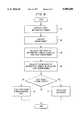
- FIG. 2illustrates a flow chart for implementing an embodiment of the present invention
- FIG. 3Aillustrates an implementation of another embodiment of the present invention
- FIG. 3Bis a cross section along the line 3--3 of FIG. 3A;
- FIG. 4is another embodiment of the present invention.
- FIG. 5is an illustration of another embodiment of the present invention.
- FIG. 6is a flow chart for implementing a preferred embodiment of the present invention.
- the supervising unitis provided in the charging apparatus (for example, a separate charger, not shown) or in the battery-powered equipment (for example, a cellular mobile phone, pager, or video cam corder, not shown).
- the supervising unithas the ability to identify individual batteries. Upon recognizing a particular battery individual, the charging apparatus or battery powered equipment will only accept recharging for a limited number of cycles. The number of available cycles is based on tests made by the manufacturer or an independent laboratory. A safety factor may also be incorporated in the number for each battery type, which safety factor can be chosen from the test data. The setting of the available cycles for the different battery types is believed to be within the skill of the ordinary artisan in possession of the instant disclosure.
- FIG. 1The exemplary implementation of such a supervising circuit 12 is shown in FIG. 1.
- N resistorsare installed, N having a minimum value of one.
- the resistorsare provided in the range of zero to ⁇ ohms.
- the resistors R1 and R2are connected between connectors C 1 , C 2 and C 3 that can be reached on the surface of the battery unit 10.
- One or more of the connectorsmay be connected to more than one resistor or to any other part of the battery, for example, the "+" pole. In this way, the value or values of the resistor or resistors can be used as a fingerprint of the battery to recognize a particular individual battery, and can be used as a key to permit recharging of the particular battery pack.
- Na number of factors may be considered. These include what is practical and the needed probability that the owner of the battery powered apparatus does not get two or more batteries with each set of resistors.
- a preferred range for the value for each resistoris between 0 to 100 k ⁇ and an open circuit.
- supervising circuit 12includes an analog to digital (A/D) converter 14 connected to the resistors and the terminal units or connectors C 1 , C 2 and C 3 of the battery unit.
- the A/D converter 14 outputprovides the digital equivalent of the resistance value to the central processing unit (CPU) 16.
- the CPU 16is connected to a memory unit 18 for storing the recharging information associated with the particular individuals.
- the memory unit 18may be a non-volatile memory or a volatile memory which is supplied with power either by the battery pack or from a separate external power source.
- the memory unit 18is a volatile memory which requires a relatively small amount of current such that the battery pack itself can supply power to the memory unit regardless of the charging condition of the battery pack.
- Reference resistance value R ref and a reference current I refare used to allow the supervising unit 12 to read the values of R 1 and R 2 to identify the battery individual.
- a current I refis run through R ref , R 1 , and R 2 and the voltage potential across the resistors is measured by the A/D converter 14.
- the potential generated by R refis entered into the A/D converter 14 for the purpose of allowing the supervising unit 12 to read the values of R 1 and R 2 regardless of the degree of energization of the battery.
- An alarm means 20is connected to the CPU 16 to allow the user to be informed that the battery pack has reached the end of its useful life.
- the alarm means 20may consist of an audio alarm, a display, an LED, a vibrating alarm, or any other suitable device.
- FIG. 2illustrates a flow chart for implementing the present invention which program is executed by the CPU 16.
- the batteryis inserted into the recharging apparatus or the battery powered equipment (step 201).
- the resistance values of R 1 and R 2are measured using I ref (step 203) which produces a measurable potential difference (voltage drop) across R 1 of the series connected resistor pair R 1 , R 2 , and resistance R ref which acts as a voltage divider circuit.
- step 205it is determined whether the individual identified by the resistors R 1 and R 2 is an earlier identified or known battery. If not, at step 206 the battery is registered and its identity is stored in the memory unit 18 and the memory 18 is incremented by one to count the number of charging cycles. Alternatively, the memory 18 can be used to track the total charging time experienced by the particular battery pack. If the individual battery is recognized at step 205, step 207 determines whether any more cycles are available to that individual battery. If so, one is added to the cycle count in the memory unit 18 associated with that individual battery (step 209). If no more cycles are available, step 208 sends an alarm or takes other action to inform the user that the life time of the individual battery is over.
- the memory 18stores the charging status of the identified battery pack, either by keeping track of the number of charging cycles the battery pack has experienced, or the total charging time. Means are provided to signal the charging status to the memory. As noted above, the charging status can be monitored by counting the number of charging cycles experienced by the battery pack or by tracking the total charging time experienced by the battery pack.
- the signalling means 22can be provided either in the supervising circuit of the battery pack, as shown in FIG. 1, or in the battery charging circuit (not shown). If the signalling means is provided in the battery charging circuit, the signal may be transmitted either by a partially separate bus or on the ordinary discharging wires. The signalling means 22 signals a change in the charging status every time the battery pack is connected to the battery charging circuit.
- the signalling means 22signals a change in the charging status as a function of the total charge which is given to the battery pack at every charge period.
- the total charging time times the current input into the batteryis monitored each time the battery pack is charged up, and that total is sent to the memory 18, to be summed with the previous stored charging time.
- the total charging timereaches a predetermined maximum, further recharging is prohibited or the user is warned as described herein.
- One alternativeis that a message is provided to the user in a display (not shown) that the lifetime of the battery is nearing an end and it should be disposed of due to safety reasons. This message may be given by light signal, on a display, by sound (buzzer or voice) or any other method that is normally used for messages.
- Another alternativeis to refuse to accept the particular battery individual anymore and provide the user with the message to that effect as in the first alternative.
- a third alternativeis that a circuit element in the battery pack may be destroyed so that the individual battery will be useless for future use. If desired, a message can be provided to the user to this effect.
- a transistormay be employed to create a short circuit between the "+" and "-" terminals of the battery which blows a fuse inside the battery pack. This embodiment is described in more detail below.
- FIGS. 3A and 3BAnother embodiment of the invention is shown in FIGS. 3A and 3B.
- a resistive inkmay be printed in an individual pattern on the surface of the battery.
- Contact springs 30may be provided on the outside of the battery pack 10 which touch the surface of the battery pack at specified points. A resistance between the springs will be used to identify and control the recharging of individual batteries according to the software program shown in FIG. 2.
- a bar code or resistive bar codemay be used to identify battery pack individuals.
- Another embodiment of the present inventionis to have individual signatures, for example, a set of magnets, disposed close to the surface of the battery pack.
- the reading of the magnetic signaturecan be implemented using any magneto-sensitive arrangement such as, for example, Hall elements or an array of such elements which feeds the supervising circuit with the information required.
- "smart cards”that is, the family of small, more or less intelligent cards with a semiconductor chip, in a contact pattern, for example, the "SIM” card used in Ericsson cellular telephones, can be used to identify individual battery packs.
- at least two connectors, of which one can be the power connector,will be connected to a chip inside the battery pack.
- the chipwill in the most simple version, be only a memory, preferably a non-volatile serial ROM or a RAM with a serial number inside.
- FIG. 4Another embodiment of the present invention is shown in FIG. 4 in which the battery pack 10' contains a circuit that will prohibit further charging of the battery pack when a predetermined number of charging cycles is approaching or has been reached or a predetermined total charging time is approaching or has been reached, or any other situation occurs such that no further charging is recommended due to safety or other reasons.
- such circuitconsists of a charge detection circuit 43 for detecting the charging of the battery pack 10', a central processing unit (CPU) 47, a memory 44, and a back up battery or capacitor 46.
- the charge detection circuit 43may be implemented as a Schmitt trigger or an analog to digital converter.
- the memory 44can be either a volatile or a non-volatile memory.
- the back up battery/capacitor 46may be omitted if the memory 44 is non-volatile memory.
- a switch 40is connected between the charge detection circuit 43 and the battery 10'.
- the switch 40for example, may be provided as an FET transistor 42 and a diode 41.
- the diode 41can be omitted in an alternative embodiment.
- the circuitrywill be able to point out these battery packs.
- the identification number provided by the resistorscould be displayed to the user on the application display, or on a separate battery pack display.
- battery packs which have been stressed by heatmay need to be replaced after a lower number of recharging cycles than battery packs that have been used under more suitable conditions.
- a temperature sensormay be provided in the battery pack to detect whether such a stress has been experienced and can so indicate to the CPU. The CPU can then consider this stress to control the number of available recharging cycles permissible for the particular individual battery.
- FIG. 5Another embodiment of the present invention as shown in FIG. 5 in which a real time clock is provided within the battery pack.
- the circuitrycan be used to communicate the real time data to the application, that is, for example, a cellular telephone. This can be accomplished by having an extra pin on the battery pack and the application. If the battery pack is of a rechargeable type, it is possible that the battery may become totally discharged. This may cause the real time circuit to lose the real time information. In such a case, it will be possible to enter date and time information from the application.
- the cellular telephone or other applicationsincludes a microprocessor 50 and a display 52 as well as a voltage regulator 54 providing a constant voltage source to the circuit elements.
- a crystal elementprovides a 32 kHz signal to the real time clock.
- the battery pack shown in FIG. 5includes a real time clock 45, an alarm 58, a 32 kHz crystal, and an arithmetic and logic unit (ALU) 59.
- a microprocessormay be used instead of the ALU 59.
- the display 52displays the time and data obtained from the real time clock 45 from the data line connected to the microprocessor 50 in the application circuit.
- the data lineis connected to a first pin provided in the battery pack which is connected to a second pin provided in the application circuit (represented in FIG. 5 by a °).
- the built-in-alarm 58 provided in the battery packfor example, a vibrator or a buzzer, may be activated at a predetermined time based on the real time clock information.
- the predetermined timemay be set by a control panel 48 on the battery pack (FIG. 4) or the control panel 56 normally used in the battery charger or in the application (FIG. 5).
- the real time clockcan also be used to activate or shut down the battery powered application in a predetermined manner.
- the predetermination of the shut down timecan be done by a control panel on the battery pack or the control panel normally used with the application equipment.
- the microprocessor 50 in the applicationplaces the application circuit in a non-operational mode, that is, it shuts off the application, when the real time clock reaches the predetermined time.
- the real time clockmay be used to control the recharging of the battery pack.
- the real time clockmay provide the basis for counting the total charging time experienced by the battery pack as described above.
- An advantage achieved by the present inventionoccurs by adding the clock to the battery pack itself since the clock will always have the power to keep the time correctly during charging and the back up battery or capacitor can be eliminated.
- the microprocessor in the application equipmentcan communicate with the clock circuit to inquire as to the current time, set an alarm and set the time. The connections would also enable the microprocessor to be woken up by the clock circuit in the event of an alarm.
- the memory and the CPU of the battery packsuch as that shown in FIG. 4, is used in conjunction with the memory and CPU in the application circuit (not shown) to make it possible for the battery powered application or the battery charger to distinguish a correct battery from a battery that is manufactured by somebody else.
- the memory unit 44contains mathematical formula that is also known to the application circuit and stored in the memory thereof (not shown).
- the applicationWhen the application is powered up, it retrieves the stored mathematical formula from the application memory (step 60). At the same time, the battery pack 10' retrieves the stored mathematical formula from the battery memory unit 44. A random number is generated by the application equipment (step 62). This random number is used as the input to the mathematical formula stored in the battery pack as well as that stored in the application. The first result of the mathematical formula is calculated in the battery pack using the random number generated in step 62 (step 64). The second result of the mathematical formula is calculated in the application using the random number generated in step 62 (step 66). The result of both calculations are communicated to the application where they are compared at step 68.
- step 70If the first result is not equal to the second result, this indicates that the battery pack is a counterfeit battery pack and the application is placed in an non-operational state (step 70). If the application is placed in the non-operational state, the reason therefor may be communicated to the user by a display or alarm. If the first result equals the second result, the application is permitted to operate at step 72. If the application is placed in the non-operational state, this reason therefore may be communicated to the user by a display or alarm.
- a modular-two addition to a number hidden in the battery packmay serve to determine whether the battery pack is counterfeit.
- the charger or applicationsends a number in serial form to the battery pack.
- the CPU in the battery packadds a number with module-two addition and returns the results to the supervising unit, the battery charger or the application.
- the supervising unitchecks whether or not the hidden number from the battery pack is a member of the accepted group of numbers.
Landscapes
- Engineering & Computer Science (AREA)
- Power Engineering (AREA)
- Charge And Discharge Circuits For Batteries Or The Like (AREA)
- Secondary Cells (AREA)
- Mobile Radio Communication Systems (AREA)
- Calculators And Similar Devices (AREA)
- Power Sources (AREA)
- Electromechanical Clocks (AREA)
- Battery Mounting, Suspending (AREA)
Abstract
Description
Claims (42)
Priority Applications (24)
| Application Number | Priority Date | Filing Date | Title |
|---|---|---|---|
| US08/213,073US5608306A (en) | 1994-03-15 | 1994-03-15 | Rechargeable battery pack with identification circuit, real time clock and authentication capability |
| DE69533410TDE69533410T2 (en) | 1994-03-15 | 1995-03-14 | Rechargeable battery pack with identification circuit, real-time clock and authentication capability |
| DE69533411TDE69533411D1 (en) | 1994-03-15 | 1995-03-14 | Rechargeable battery pack with identification circuit, real-time clock and authentication capability |
| EP99119972AEP0984541B1 (en) | 1994-03-15 | 1995-03-14 | Rechargeable battery pack with identification circuit, real time clock and authentication capability |
| EP99119973AEP0984542B1 (en) | 1994-03-15 | 1995-03-14 | Rechargeable battery pack with identification circuit, real time clock and authentication capability |
| DE69533412TDE69533412T2 (en) | 1994-03-15 | 1995-03-14 | Rechargeable battery pack with identification circuit, real-time clock and authentication capability |
| EP99119971AEP0984540B1 (en) | 1994-03-15 | 1995-03-14 | Rechargeable battery pack with identification circuit, real time clock and authentication capability |
| AT99119973TATE274252T1 (en) | 1994-03-15 | 1995-03-14 | RECHARGEABLE BATTERY PACK WITH IDENTIFICATION CIRCUIT, REAL-TIME CLOCK AND AUTHENTICATION CAPABILITY |
| AT99119972TATE274251T1 (en) | 1994-03-15 | 1995-03-14 | RECHARGEABLE BATTERY PACK WITH IDENTIFICATION CIRCUIT, REAL-TIME CLOCK AND AUTHENTICATION CAPABILITY |
| EP95850057AEP0673103A1 (en) | 1994-03-15 | 1995-03-14 | Rechargeable battery pack with identification circuit, real time clock and authentication capability |
| AT99119971TATE274250T1 (en) | 1994-03-15 | 1995-03-14 | RECHARGEABLE BATTERY PACK WITH IDENTIFICATION CIRCUIT, REAL-TIME CLOCK AND AUTHENTICATION CAPABILITY |
| FI955481AFI955481L (en) | 1994-03-15 | 1995-03-15 | Rechargeable battery unit comprising a detection circuit, a real-time clock and an enabling function |
| JP52414395AJP3703835B2 (en) | 1994-03-15 | 1995-03-15 | Rechargeable battery pack with identification circuit, real-time clock and authentication capability |
| AU19980/95AAU687175B2 (en) | 1994-03-15 | 1995-03-15 | Rechargeable battery pack with identification circuit, real time clock and authentication capability |
| KR1019950705095AKR100379587B1 (en) | 1994-03-15 | 1995-03-15 | Rechargeable Battery Pack with Identification Circuit, Real Time Clock and Authentication Capability |
| CN95190368ACN1045697C (en) | 1994-03-15 | 1995-03-15 | An identification and recharging device for a specific battery pack |
| PCT/US1995/003185WO1995025375A1 (en) | 1994-03-15 | 1995-03-15 | Rechargeable battery pack with identification circuit, real time clock and authentication capability |
| ZA952123AZA952123B (en) | 1994-03-15 | 1995-03-15 | Rechargeable battery pack with identification circuit real time clock and authentication capability |
| CA002162861ACA2162861C (en) | 1994-03-15 | 1995-03-15 | Rechargeable battery pack with identification circuit, real time clock and authentication capability |
| MXPA/A/1995/004666AMXPA95004666A (en) | 1994-03-16 | 1995-11-07 | Rechargeable battery pack with deidentification circuit, real time clock and autenticac capacity |
| CN98118887ACN1216871A (en) | 1994-03-15 | 1998-09-01 | Rechargeable battery pack with identification circuit, real time clock and authentiation cap ability |
| CN98118888ACN1107988C (en) | 1994-03-15 | 1998-09-01 | Rechargeable buttery pack with identification circuit, real time clock and authentication capability |
| CN99102109ACN1119668C (en) | 1994-03-15 | 1999-02-06 | Rechargeable battery pack with identification circuit |
| HK00101433.3AHK1022523B (en) | 1994-03-15 | 2000-03-07 | Apparatus for identifying and recharging an individual battery pack |
Applications Claiming Priority (1)
| Application Number | Priority Date | Filing Date | Title |
|---|---|---|---|
| US08/213,073US5608306A (en) | 1994-03-15 | 1994-03-15 | Rechargeable battery pack with identification circuit, real time clock and authentication capability |
Publications (1)
| Publication Number | Publication Date |
|---|---|
| US5608306Atrue US5608306A (en) | 1997-03-04 |
Family
ID=22793644
Family Applications (1)
| Application Number | Title | Priority Date | Filing Date |
|---|---|---|---|
| US08/213,073Expired - LifetimeUS5608306A (en) | 1994-03-15 | 1994-03-15 | Rechargeable battery pack with identification circuit, real time clock and authentication capability |
Country Status (12)
| Country | Link |
|---|---|
| US (1) | US5608306A (en) |
| EP (4) | EP0984540B1 (en) |
| JP (1) | JP3703835B2 (en) |
| KR (1) | KR100379587B1 (en) |
| CN (4) | CN1045697C (en) |
| AT (3) | ATE274250T1 (en) |
| AU (1) | AU687175B2 (en) |
| CA (1) | CA2162861C (en) |
| DE (3) | DE69533410T2 (en) |
| FI (1) | FI955481L (en) |
| WO (1) | WO1995025375A1 (en) |
| ZA (1) | ZA952123B (en) |
Cited By (96)
| Publication number | Priority date | Publication date | Assignee | Title |
|---|---|---|---|---|
| WO1997030643A1 (en)* | 1996-02-22 | 1997-08-28 | Apollo Camera, L.L.C. | Cordless bipolar electrocautery unit with automatic power control |
| US5825161A (en)* | 1996-10-01 | 1998-10-20 | Uniden Corporation | Battery pack and charging device |
| US5850134A (en)* | 1997-01-06 | 1998-12-15 | Samsung Electronics Co., Ltd. | Battery-powered equipment automatically detecting battery types |
| US5867008A (en)* | 1996-06-05 | 1999-02-02 | Double-Time Battery Corporation | Overcharge protection circuitry for rechargeable battery pack |
| WO1999000863A3 (en)* | 1997-06-27 | 1999-03-25 | Motorola Inc | Battery charging system having lock-out circuitry |
| US5903131A (en)* | 1993-08-09 | 1999-05-11 | Kabushiki Kaisha Toshiba | Battery set structure and charge/discharge control apparatus for lithium-ion battery |
| EP1025631A1 (en)* | 1997-10-28 | 2000-08-09 | Telefonaktiebolaget LM Ericsson (publ) | An identification arrangement and method |
| US6218806B1 (en) | 1998-06-03 | 2001-04-17 | Black & Decker Inc. | Method and apparatus for obtaining product use information |
| US6249105B1 (en)* | 1998-11-13 | 2001-06-19 | Neal Andrews | System and method for detecting performance components of a battery pack |
| US6252378B1 (en) | 2000-01-10 | 2001-06-26 | Snap-On Technologies, Inc. | Usage counter for portable jump-starting battery unit |
| US20020016931A1 (en)* | 2000-02-22 | 2002-02-07 | International Business Machines Corporation | Electric power unit, electric power unit controller, electric power unit controlling method, and computer |
| US6351130B1 (en)* | 1998-06-26 | 2002-02-26 | Fraunhofer-Gesellschaft Zur Foerderung Der Angewandten Foschung E.V. | Device for testing solar home systems |
| US6359417B1 (en)* | 1999-10-20 | 2002-03-19 | Sony International (Europe) Gmbh | Rechargeable battery pack for a mobile terminal with unique identification and time reference |
| EP1199783A1 (en)* | 2000-10-16 | 2002-04-24 | Sony International (Europe) GmbH | Battery management system |
| EP1241767A1 (en)* | 2001-03-15 | 2002-09-18 | Sony International (Europe) GmbH | Real time clock synchronisation for mobile devices with rechargeable battery using the charger |
| US20030054229A1 (en)* | 2001-09-19 | 2003-03-20 | Shigefumi Odaohhara | Electrical apparatus, computer system, intelligent battery, battery diagnosis method, batter-state display method, and program |
| US6605922B2 (en)* | 2001-11-30 | 2003-08-12 | Sanyo Electric Co., Ltd. | Battery pack provided with authentication circuitry |
| US6625477B1 (en)* | 1996-06-12 | 2003-09-23 | Ericsson Inc. | Apparatus and method for identifying and charging batteries of different types |
| US6789205B1 (en)* | 2000-05-19 | 2004-09-07 | Motorola, Inc. | System for determining intrinsic safety status of the combination of a communication device and a battery |
| US20040251907A1 (en)* | 2003-06-11 | 2004-12-16 | Kalley Terrence D. | Part tester and method |
| US20050010782A1 (en)* | 2003-06-20 | 2005-01-13 | Sanyo Electric Co., Ltd. | Authentication system and ID generator |
| US20050050325A1 (en)* | 2003-08-26 | 2005-03-03 | Kenichi Ohkubo | ID check device, ID generation device, and authentication system |
| US20060043975A1 (en)* | 2004-08-31 | 2006-03-02 | Eaglepicher Technologies, Llc | System and method for nondestructive testing of thermal batteries |
| US20060119315A1 (en)* | 2004-12-02 | 2006-06-08 | Taichi Sasaki | Battery pack, charging control method, and application device |
| AU2005232316B2 (en)* | 2004-11-26 | 2006-07-13 | Sony Interactive Entertainment Inc. | Battery and authentication requesting device |
| US20060178170A1 (en)* | 2005-02-08 | 2006-08-10 | Samsung Electronics Co., Ltd. | Wireless communication device having battery authentication, and associated method |
| US20060220613A1 (en)* | 2005-03-29 | 2006-10-05 | Fujinon Corporation | Electronic endoscope |
| US20070214293A1 (en)* | 2006-03-10 | 2007-09-13 | Gunnar Gangstoe | Random number generator in a battery pack |
| US20070226497A1 (en)* | 2006-03-27 | 2007-09-27 | Taylor John P | Communication protocol for device authentication |
| CN100341366C (en)* | 2004-07-30 | 2007-10-03 | 乐金电子(中国)研究开发中心有限公司 | Identifier of portable terminal cell port and its method |
| RU2314601C2 (en)* | 2004-12-02 | 2008-01-10 | Сони Корпорейшн | Battery bank, method for charge control, and application device |
| US20080140255A1 (en)* | 2005-02-18 | 2008-06-12 | Irobot Corporation | Autonomous surface cleaning robot for wet and dry cleaning |
| CN100420083C (en)* | 2002-12-20 | 2008-09-17 | 北京六合万通微电子技术有限公司 | Anti-fogery system of chargeable battery |
| US20080266126A1 (en)* | 2005-03-10 | 2008-10-30 | Sony Corporation | Battery Residual Quantity Display Method and Electronic Equipment |
| US20080282494A1 (en)* | 2005-12-02 | 2008-11-20 | Irobot Corporation | Modular robot |
| US20090135633A1 (en)* | 2005-10-14 | 2009-05-28 | Akira Ikeuchi | Ac Adapter, Electronic Apparatus and Power Supply System |
| US20090292918A1 (en)* | 2005-12-20 | 2009-11-26 | Panasonic Corporation | Authentication system and authentication device |
| US20100148721A1 (en)* | 2005-10-14 | 2010-06-17 | Research In Motion Limited | Battery pack authentication for a mobile device |
| US20100178961A1 (en)* | 2005-10-14 | 2010-07-15 | Research In Motion Limited | Mobile device with a smart battery |
| US20100181960A1 (en)* | 2007-06-27 | 2010-07-22 | Wolf Matthias | Rechargeable power supply device having an identification device |
| US20100197366A1 (en)* | 2005-10-14 | 2010-08-05 | Research In Motion Limited | Interface and communication protocol for a mobile device with a smart battery |
| US20100241853A1 (en)* | 2006-03-27 | 2010-09-23 | Taylor John P | System and method for generating a plaintext / cyphertext database for use in device authentication |
| US20110001485A1 (en)* | 2008-09-07 | 2011-01-06 | Feight Laurence V | Energy management for an electronic device |
| CN102027628A (en)* | 2009-11-30 | 2011-04-20 | 郑润珥 | Battery pack and active cell balancing battery management system including the same |
| WO2011078086A1 (en) | 2009-12-25 | 2011-06-30 | 株式会社マキタ | Battery pack for electric tool, and battery connection device |
| US20110215768A1 (en)* | 2006-08-31 | 2011-09-08 | Semiconductor Energy Laboratory Co., Ltd. | Power storage device and semiconductor device provided with the power storage device |
| US20120032638A1 (en)* | 2009-11-30 | 2012-02-09 | Eun-Ey Jung | Battery pack and active cell balancing battery management system including the same |
| US8120363B2 (en) | 2008-11-24 | 2012-02-21 | Cummins Power Generation Ip, Inc. | Voltage drop compensation for an electric power storage device charging system |
| US20120049787A1 (en)* | 2010-08-27 | 2012-03-01 | Denso Corporation | Battery management apparatus |
| US8239992B2 (en) | 2007-05-09 | 2012-08-14 | Irobot Corporation | Compact autonomous coverage robot |
| US8253368B2 (en) | 2004-01-28 | 2012-08-28 | Irobot Corporation | Debris sensor for cleaning apparatus |
| WO2012078613A3 (en)* | 2010-12-06 | 2012-08-30 | Coda Automotive, Inc. | Electrochemical cell monitoring and balancing circuit with self-diagnostic feature |
| EP2530807A1 (en)* | 2011-06-01 | 2012-12-05 | HTC Corporation | Electrical apparatus and verification method for battery module thereof |
| US8368339B2 (en) | 2001-01-24 | 2013-02-05 | Irobot Corporation | Robot confinement |
| US8374721B2 (en) | 2005-12-02 | 2013-02-12 | Irobot Corporation | Robot system |
| US8380350B2 (en) | 2005-12-02 | 2013-02-19 | Irobot Corporation | Autonomous coverage robot navigation system |
| US8386081B2 (en) | 2002-09-13 | 2013-02-26 | Irobot Corporation | Navigational control system for a robotic device |
| US8382906B2 (en) | 2005-02-18 | 2013-02-26 | Irobot Corporation | Autonomous surface cleaning robot for wet cleaning |
| US8390251B2 (en) | 2004-01-21 | 2013-03-05 | Irobot Corporation | Autonomous robot auto-docking and energy management systems and methods |
| US8396592B2 (en) | 2001-06-12 | 2013-03-12 | Irobot Corporation | Method and system for multi-mode coverage for an autonomous robot |
| US8412377B2 (en) | 2000-01-24 | 2013-04-02 | Irobot Corporation | Obstacle following sensor scheme for a mobile robot |
| US8417383B2 (en) | 2006-05-31 | 2013-04-09 | Irobot Corporation | Detecting robot stasis |
| US8418303B2 (en) | 2006-05-19 | 2013-04-16 | Irobot Corporation | Cleaning robot roller processing |
| US8428778B2 (en) | 2002-09-13 | 2013-04-23 | Irobot Corporation | Navigational control system for a robotic device |
| US20130113429A1 (en)* | 2011-11-04 | 2013-05-09 | Bong-Young KIM | Battery pack, battery management system, and battery system |
| US8463438B2 (en) | 2001-06-12 | 2013-06-11 | Irobot Corporation | Method and system for multi-mode coverage for an autonomous robot |
| US8474090B2 (en) | 2002-01-03 | 2013-07-02 | Irobot Corporation | Autonomous floor-cleaning robot |
| US8515578B2 (en) | 2002-09-13 | 2013-08-20 | Irobot Corporation | Navigational control system for a robotic device |
| US8594840B1 (en) | 2004-07-07 | 2013-11-26 | Irobot Corporation | Celestial navigation system for an autonomous robot |
| US8600553B2 (en) | 2005-12-02 | 2013-12-03 | Irobot Corporation | Coverage robot mobility |
| US8725330B2 (en) | 2010-06-02 | 2014-05-13 | Bryan Marc Failing | Increasing vehicle security |
| US8739355B2 (en) | 2005-02-18 | 2014-06-03 | Irobot Corporation | Autonomous surface cleaning robot for dry cleaning |
| US8780342B2 (en) | 2004-03-29 | 2014-07-15 | Irobot Corporation | Methods and apparatus for position estimation using reflected light sources |
| US8788092B2 (en) | 2000-01-24 | 2014-07-22 | Irobot Corporation | Obstacle following sensor scheme for a mobile robot |
| US8800107B2 (en) | 2010-02-16 | 2014-08-12 | Irobot Corporation | Vacuum brush |
| US8930023B2 (en) | 2009-11-06 | 2015-01-06 | Irobot Corporation | Localization by learning of wave-signal distributions |
| US8972052B2 (en) | 2004-07-07 | 2015-03-03 | Irobot Corporation | Celestial navigation system for an autonomous vehicle |
| US9008835B2 (en) | 2004-06-24 | 2015-04-14 | Irobot Corporation | Remote control scheduler and method for autonomous robotic device |
| WO2015120300A1 (en)* | 2014-02-06 | 2015-08-13 | Dichiara E Ismael | Mobile multi-charger for mobile device external batteries |
| US9114181B2 (en) | 2011-03-30 | 2015-08-25 | Covidien Lp | Process of cooling surgical device battery before or during high temperature sterilization |
| US9142992B2 (en) | 2005-10-21 | 2015-09-22 | Stryker Corporation | Battery with an internal microcontroller that draws different currents from the cells internal to the battery based on the temperature of the battery |
| US9320398B2 (en) | 2005-12-02 | 2016-04-26 | Irobot Corporation | Autonomous coverage robots |
| WO2017083272A1 (en)* | 2015-11-09 | 2017-05-18 | Johnson Industries, Inc. | Battery exercising device |
| US9929575B2 (en)* | 2011-08-02 | 2018-03-27 | Sony Interactive Entertainment Inc. | Electrical apparatus |
| US10177589B2 (en) | 2015-11-09 | 2019-01-08 | Johnson Industries, Inc. | Battery exercising device |
| US10408884B2 (en) | 2016-03-16 | 2019-09-10 | Tti (Macao Commercial Offshore) Limited | Power tool battery pack with wireless communication |
| US10459025B1 (en) | 2018-04-04 | 2019-10-29 | Schweitzer Engineering Laboratories, Inc. | System to reduce start-up times in line-mounted fault detectors |
| US10498160B2 (en) | 2015-08-03 | 2019-12-03 | Massachusetts Institute Of Technology | Efficiency maximization for device-to-device wireless charging |
| US10651687B2 (en) | 2018-02-08 | 2020-05-12 | Massachusetts Institute Of Technology | Detuning for a resonant wireless power transfer system including cryptography |
| US10886765B2 (en) | 2015-11-09 | 2021-01-05 | Johnson Industries, Inc. | Lighted connector for a battery cable |
| US11018526B2 (en) | 2018-02-08 | 2021-05-25 | Massachusetts Institute Of Technology | Detuning for a resonant wireless power transfer system including cooperative power sharing |
| US11105834B2 (en) | 2019-09-19 | 2021-08-31 | Schweitzer Engineering Laboratories, Inc. | Line-powered current measurement device |
| US20220116103A1 (en)* | 2020-10-09 | 2022-04-14 | Schweitzer Engineering Laboratories, Inc. | Wireless radio repeater for electric power distribution system |
| US11397198B2 (en) | 2019-08-23 | 2022-07-26 | Schweitzer Engineering Laboratories, Inc. | Wireless current sensor |
| US12170450B2 (en) | 2020-11-20 | 2024-12-17 | Milwaukee Electric Tool Corporation | Systems and methods for identifying a battery pack for a battery pack powered power tool |
| US12184343B2 (en) | 2021-10-08 | 2024-12-31 | Schweitzer Engineering Laboratories, Inc. | Systems and methods to communicate data between devices of an electric power delivery system |
Families Citing this family (30)
| Publication number | Priority date | Publication date | Assignee | Title |
|---|---|---|---|---|
| KR0181164B1 (en)* | 1996-07-06 | 1999-05-15 | 삼성전자주식회사 | Multi battery common charging device and control method |
| US5717307A (en)* | 1996-07-24 | 1998-02-10 | Motorola, Inc. | Apparatus and method for identifying the type and brand of a battery for a portable device |
| US5814969A (en)* | 1996-09-23 | 1998-09-29 | Ericsson Inc. | Apparatus for selectively activating a plurality of devices |
| JP4042813B2 (en) | 1997-10-09 | 2008-02-06 | 名糖産業株式会社 | Method for producing dextran with reduced boron content |
| EP0926798A1 (en)* | 1997-12-24 | 1999-06-30 | Nokia Mobile Phones Ltd. | Battery type determination for a radio telephone or battery charger |
| EP1635511B1 (en) | 1998-10-05 | 2009-05-27 | Sony Deutschland GmbH | Transmission of random access bursts with at least one message part |
| JP2001002488A (en)* | 1999-06-17 | 2001-01-09 | Daicel Chem Ind Ltd | Gas generating composition for pretensioner |
| US6191551B1 (en)* | 1999-06-30 | 2001-02-20 | Research In Motion Limited | Automatic battery detection system and method for detecting a rechargeable battery with low remaining charge |
| EP1255360A1 (en)* | 2001-05-03 | 2002-11-06 | Sony International (Europe) GmbH | Battery with oscillator for mobile terminal |
| CA2494099A1 (en)* | 2002-07-31 | 2004-02-05 | Rayovac Corporation | Method and apparatus for detecting the presence of rechargeable batteries |
| FI20031089L (en)* | 2003-07-17 | 2005-01-18 | Avantone Oy | A method for identifying pieces and a system for determining the content of a sign |
| JP4097582B2 (en) | 2003-09-12 | 2008-06-11 | 三洋電機株式会社 | Pack battery, electric device connectable to pack battery, and pack battery type determination method |
| JP2005151368A (en) | 2003-11-19 | 2005-06-09 | Matsushita Electric Ind Co Ltd | Authentication system |
| KR100690729B1 (en)* | 2004-10-04 | 2007-03-09 | 엘지전자 주식회사 | Battery classification operation on / off device and method of mobile communication terminal |
| DE102004059006A1 (en)* | 2004-12-08 | 2006-06-14 | Audia Akustik Gmbh | Charging accumulator in hearing aid involves charge controller arranged in hearing aid which is charged in receiving bowl along with transmitter device having switching mechanism, which has no contact with accumulator |
| CN1862280B (en)* | 2005-05-10 | 2013-04-24 | 电池公司 | Battery management system and device with abnormity report function |
| DE102005024227A1 (en)* | 2005-05-25 | 2006-11-30 | Audia Akustik Gmbh | Method and device for inductive charging of hearing aids |
| KR100765234B1 (en) | 2005-06-09 | 2007-10-09 | 엘지전자 주식회사 | Charging method of mobile communication terminal using authentication code, and mobile communication terminal for same |
| US7250612B2 (en) | 2005-09-28 | 2007-07-31 | General Electric Company | Devices and methods capable of authenticating batteries |
| JP2008086192A (en)* | 2006-08-31 | 2008-04-10 | Semiconductor Energy Lab Co Ltd | Storage device and semiconductor device having the storage device |
| JP5151506B2 (en)* | 2008-01-28 | 2013-02-27 | 日立工機株式会社 | Battery pack, charging device and charging system for charging the same |
| FI20085456A7 (en) | 2008-05-15 | 2009-11-16 | Valtion Teknillinen Tutkimuskeskus | Method and apparatus for recognizing an electronic code |
| EP2689513A2 (en)* | 2011-03-25 | 2014-01-29 | Hitachi Koki Co., Ltd. | Charger and power supply system |
| CN102820970B (en)* | 2011-06-08 | 2016-08-03 | 宏达国际电子股份有限公司 | Authentication method for electronic device and its battery module |
| JP5404831B2 (en)* | 2012-02-17 | 2014-02-05 | 三菱電機株式会社 | Charging system |
| WO2013134785A2 (en)* | 2012-03-09 | 2013-09-12 | Oliso, INC. | Cooking appliance |
| GB2528712B (en) | 2014-07-29 | 2019-03-27 | Nicoventures Holdings Ltd | E-cigarette and re-charging pack |
| DE102015103193B4 (en)* | 2015-03-05 | 2025-08-14 | Dr. Ing. H.C. F. Porsche Aktiengesellschaft | Method and device for setting up an on-board charger in an electrically powered vehicle |
| TWI858769B (en)* | 2023-06-13 | 2024-10-11 | 加百裕工業股份有限公司 | Fool-proof battery pack and automatic identification method of battery identity |
| CN116707091B (en)* | 2023-06-26 | 2024-08-09 | 北京领创医谷科技发展有限责任公司 | Intelligent charging cabin with recognition function |
Citations (33)
| Publication number | Priority date | Publication date | Assignee | Title |
|---|---|---|---|---|
| US4289836A (en)* | 1980-03-05 | 1981-09-15 | Lemelson Jerome H | Rechargeable electric battery system |
| US4363407A (en)* | 1981-01-22 | 1982-12-14 | Polaroid Corporation | Method and system for testing and sorting batteries |
| US4455523A (en)* | 1982-06-07 | 1984-06-19 | Norand Corporation | Portable battery powered system |
| DE3331360A1 (en)* | 1983-08-31 | 1985-03-14 | Varta Batterie Ag, 3000 Hannover | Accumulator battery with an electronic module integrated into the housing cover for functional monitoring |
| US4553081A (en)* | 1982-06-07 | 1985-11-12 | Norand Corporation | Portable battery powered system |
| US4593409A (en)* | 1984-04-04 | 1986-06-03 | Motorola, Inc. | Transceiver protection arrangement |
| US4638237A (en)* | 1985-01-03 | 1987-01-20 | Pulse Electronics, Inc. | Battery condition indicator |
| EP0226360A2 (en)* | 1985-12-04 | 1987-06-24 | Powerplex Technologies, Inc. | A zener diode looping element for protecting a battery cell |
| US4680527A (en)* | 1986-08-06 | 1987-07-14 | Motorola, Inc. | Electrical battery including apparatus for current sensing |
| US4700375A (en)* | 1986-10-10 | 1987-10-13 | Motorola, Inc. | Battery charging, reset, and data transfer system |
| US4716354A (en)* | 1985-11-12 | 1987-12-29 | Norand Corporation | Automatic voltage regulator means providing a dual low power responsive and output-voltage-controlling regulator signal particularly for a plural source battery powered system |
| US4743831A (en)* | 1986-09-12 | 1988-05-10 | Troxler Electronic Laboratories, Inc. | Apparatus and method for indicating remaining battery life in a battery powered device |
| US4888702A (en)* | 1987-08-20 | 1989-12-19 | Integrated Power Corporation | Photovoltaic system controller |
| US4961043A (en)* | 1988-03-15 | 1990-10-02 | Norand Corporation | Battery conditioning system having communication with battery parameter memory means in conjunction with battery conditioning |
| US4965738A (en)* | 1988-05-03 | 1990-10-23 | Anton/Bauer, Inc. | Intelligent battery system |
| EP0394074A2 (en)* | 1989-04-21 | 1990-10-24 | Motorola, Inc. | Method and apparatus for determining battery type and modifying operating characteristics |
| US4977393A (en)* | 1988-07-07 | 1990-12-11 | Diehl Gmbh & Co. | Method and apparatus for monitoring the condition of charge of a battery connected to an appliance and including counters counted with respect to the time and drain of the battery |
| US5023591A (en)* | 1989-11-15 | 1991-06-11 | Allen V. Edwards | Anti-theft control apparatus |
| US5029188A (en)* | 1989-11-03 | 1991-07-02 | Joyner Engineers And Trainers | Apparatus for monitoring operation cycles of an electrically actuated device |
| US5057383A (en)* | 1990-03-30 | 1991-10-15 | Anton/Bauer, Inc | Battery system |
| JPH0496627A (en)* | 1990-08-11 | 1992-03-30 | Canon Inc | Power supply circuit having charging function and printer |
| US5111128A (en)* | 1990-12-17 | 1992-05-05 | Motorola, Inc. | Battery identification apparatus |
| US5136620A (en)* | 1990-12-31 | 1992-08-04 | Eaves Stephen S | Battery charge cycle counter |
| US5150031A (en)* | 1988-09-30 | 1992-09-22 | Motorola, Inc. | Battery charging system |
| US5184059A (en)* | 1991-09-16 | 1993-02-02 | Motorola, Inc. | Expanded battery capacity identification scheme and apparatus |
| US5200686A (en)* | 1991-10-10 | 1993-04-06 | Motorola, Inc. | Method and apparatus for determining battery type |
| US5206097A (en)* | 1991-06-05 | 1993-04-27 | Motorola, Inc. | Battery package having a communication window |
| US5248929A (en)* | 1992-04-30 | 1993-09-28 | Murata Machinery, Ltd. | Battery time monitor for cellular telephone |
| JPH0646533A (en)* | 1992-07-23 | 1994-02-18 | Nec Corp | Charger for nickel cadmiun battery |
| JPH06186310A (en)* | 1992-12-18 | 1994-07-08 | Fujitsu Ltd | Battery residual quantity prediction device |
| US5349535A (en)* | 1992-10-20 | 1994-09-20 | Digicomp Research Corporation | Battery condition monitoring and recording system for electric vehicles |
| US5350993A (en)* | 1992-01-20 | 1994-09-27 | Sanyo Electric Co., Ltd. | Power supply |
| US5399446A (en)* | 1992-06-30 | 1995-03-21 | Sony Corporation | Battery cartridge having a terminal for transferring information therefrom |
Family Cites Families (6)
| Publication number | Priority date | Publication date | Assignee | Title |
|---|---|---|---|---|
| CN85202831U (en)* | 1985-07-11 | 1987-05-20 | 朱汉雄 | Printed electric resistance |
| CN2044379U (en)* | 1988-03-28 | 1989-09-13 | 东北工学院 | Monitor for accumulator voltage |
| DE3815001A1 (en)* | 1988-05-03 | 1989-11-16 | Ullmann Ulo Werk | DEVICE FOR CHARGING ACCUMULATORS |
| JPH02294231A (en)* | 1989-05-01 | 1990-12-05 | Fujikura Ltd | Charging apparatus for interchangeable charging battery pack |
| JP3202761B2 (en)* | 1991-05-28 | 2001-08-27 | 松下電工株式会社 | Charge control device |
| JP3244737B2 (en)* | 1991-12-24 | 2002-01-07 | 松下電工株式会社 | Battery life notification device |
- 1994
- 1994-03-15USUS08/213,073patent/US5608306A/ennot_activeExpired - Lifetime
- 1995
- 1995-03-14DEDE69533410Tpatent/DE69533410T2/ennot_activeExpired - Lifetime
- 1995-03-14DEDE69533411Tpatent/DE69533411D1/ennot_activeExpired - Lifetime
- 1995-03-14ATAT99119971Tpatent/ATE274250T1/ennot_activeIP Right Cessation
- 1995-03-14EPEP99119971Apatent/EP0984540B1/ennot_activeExpired - Lifetime
- 1995-03-14ATAT99119973Tpatent/ATE274252T1/ennot_activeIP Right Cessation
- 1995-03-14EPEP99119972Apatent/EP0984541B1/ennot_activeExpired - Lifetime
- 1995-03-14DEDE69533412Tpatent/DE69533412T2/ennot_activeExpired - Lifetime
- 1995-03-14EPEP99119973Apatent/EP0984542B1/ennot_activeExpired - Lifetime
- 1995-03-14EPEP95850057Apatent/EP0673103A1/ennot_activeCeased
- 1995-03-14ATAT99119972Tpatent/ATE274251T1/ennot_activeIP Right Cessation
- 1995-03-15CNCN95190368Apatent/CN1045697C/ennot_activeExpired - Lifetime
- 1995-03-15CACA002162861Apatent/CA2162861C/ennot_activeExpired - Lifetime
- 1995-03-15KRKR1019950705095Apatent/KR100379587B1/ennot_activeExpired - Lifetime
- 1995-03-15JPJP52414395Apatent/JP3703835B2/ennot_activeExpired - Lifetime
- 1995-03-15FIFI955481Apatent/FI955481L/ennot_activeApplication Discontinuation
- 1995-03-15AUAU19980/95Apatent/AU687175B2/ennot_activeExpired
- 1995-03-15WOPCT/US1995/003185patent/WO1995025375A1/enactiveApplication Filing
- 1995-03-15ZAZA952123Apatent/ZA952123B/enunknown
- 1998
- 1998-09-01CNCN98118887Apatent/CN1216871A/enactivePending
- 1998-09-01CNCN98118888Apatent/CN1107988C/ennot_activeExpired - Lifetime
- 1999
- 1999-02-06CNCN99102109Apatent/CN1119668C/ennot_activeExpired - Lifetime
Patent Citations (33)
| Publication number | Priority date | Publication date | Assignee | Title |
|---|---|---|---|---|
| US4289836A (en)* | 1980-03-05 | 1981-09-15 | Lemelson Jerome H | Rechargeable electric battery system |
| US4363407A (en)* | 1981-01-22 | 1982-12-14 | Polaroid Corporation | Method and system for testing and sorting batteries |
| US4455523A (en)* | 1982-06-07 | 1984-06-19 | Norand Corporation | Portable battery powered system |
| US4553081A (en)* | 1982-06-07 | 1985-11-12 | Norand Corporation | Portable battery powered system |
| DE3331360A1 (en)* | 1983-08-31 | 1985-03-14 | Varta Batterie Ag, 3000 Hannover | Accumulator battery with an electronic module integrated into the housing cover for functional monitoring |
| US4593409A (en)* | 1984-04-04 | 1986-06-03 | Motorola, Inc. | Transceiver protection arrangement |
| US4638237A (en)* | 1985-01-03 | 1987-01-20 | Pulse Electronics, Inc. | Battery condition indicator |
| US4716354A (en)* | 1985-11-12 | 1987-12-29 | Norand Corporation | Automatic voltage regulator means providing a dual low power responsive and output-voltage-controlling regulator signal particularly for a plural source battery powered system |
| EP0226360A2 (en)* | 1985-12-04 | 1987-06-24 | Powerplex Technologies, Inc. | A zener diode looping element for protecting a battery cell |
| US4680527A (en)* | 1986-08-06 | 1987-07-14 | Motorola, Inc. | Electrical battery including apparatus for current sensing |
| US4743831A (en)* | 1986-09-12 | 1988-05-10 | Troxler Electronic Laboratories, Inc. | Apparatus and method for indicating remaining battery life in a battery powered device |
| US4700375A (en)* | 1986-10-10 | 1987-10-13 | Motorola, Inc. | Battery charging, reset, and data transfer system |
| US4888702A (en)* | 1987-08-20 | 1989-12-19 | Integrated Power Corporation | Photovoltaic system controller |
| US4961043A (en)* | 1988-03-15 | 1990-10-02 | Norand Corporation | Battery conditioning system having communication with battery parameter memory means in conjunction with battery conditioning |
| US4965738A (en)* | 1988-05-03 | 1990-10-23 | Anton/Bauer, Inc. | Intelligent battery system |
| US4977393A (en)* | 1988-07-07 | 1990-12-11 | Diehl Gmbh & Co. | Method and apparatus for monitoring the condition of charge of a battery connected to an appliance and including counters counted with respect to the time and drain of the battery |
| US5150031A (en)* | 1988-09-30 | 1992-09-22 | Motorola, Inc. | Battery charging system |
| EP0394074A2 (en)* | 1989-04-21 | 1990-10-24 | Motorola, Inc. | Method and apparatus for determining battery type and modifying operating characteristics |
| US5029188A (en)* | 1989-11-03 | 1991-07-02 | Joyner Engineers And Trainers | Apparatus for monitoring operation cycles of an electrically actuated device |
| US5023591A (en)* | 1989-11-15 | 1991-06-11 | Allen V. Edwards | Anti-theft control apparatus |
| US5057383A (en)* | 1990-03-30 | 1991-10-15 | Anton/Bauer, Inc | Battery system |
| JPH0496627A (en)* | 1990-08-11 | 1992-03-30 | Canon Inc | Power supply circuit having charging function and printer |
| US5111128A (en)* | 1990-12-17 | 1992-05-05 | Motorola, Inc. | Battery identification apparatus |
| US5136620A (en)* | 1990-12-31 | 1992-08-04 | Eaves Stephen S | Battery charge cycle counter |
| US5206097A (en)* | 1991-06-05 | 1993-04-27 | Motorola, Inc. | Battery package having a communication window |
| US5184059A (en)* | 1991-09-16 | 1993-02-02 | Motorola, Inc. | Expanded battery capacity identification scheme and apparatus |
| US5200686A (en)* | 1991-10-10 | 1993-04-06 | Motorola, Inc. | Method and apparatus for determining battery type |
| US5350993A (en)* | 1992-01-20 | 1994-09-27 | Sanyo Electric Co., Ltd. | Power supply |
| US5248929A (en)* | 1992-04-30 | 1993-09-28 | Murata Machinery, Ltd. | Battery time monitor for cellular telephone |
| US5399446A (en)* | 1992-06-30 | 1995-03-21 | Sony Corporation | Battery cartridge having a terminal for transferring information therefrom |
| JPH0646533A (en)* | 1992-07-23 | 1994-02-18 | Nec Corp | Charger for nickel cadmiun battery |
| US5349535A (en)* | 1992-10-20 | 1994-09-20 | Digicomp Research Corporation | Battery condition monitoring and recording system for electric vehicles |
| JPH06186310A (en)* | 1992-12-18 | 1994-07-08 | Fujitsu Ltd | Battery residual quantity prediction device |
Cited By (225)
| Publication number | Priority date | Publication date | Assignee | Title |
|---|---|---|---|---|
| US5903131A (en)* | 1993-08-09 | 1999-05-11 | Kabushiki Kaisha Toshiba | Battery set structure and charge/discharge control apparatus for lithium-ion battery |
| US5792138A (en)* | 1996-02-22 | 1998-08-11 | Apollo Camera, Llc | Cordless bipolar electrocautery unit with automatic power control |
| WO1997030643A1 (en)* | 1996-02-22 | 1997-08-28 | Apollo Camera, L.L.C. | Cordless bipolar electrocautery unit with automatic power control |
| US5867008A (en)* | 1996-06-05 | 1999-02-02 | Double-Time Battery Corporation | Overcharge protection circuitry for rechargeable battery pack |
| US6625477B1 (en)* | 1996-06-12 | 2003-09-23 | Ericsson Inc. | Apparatus and method for identifying and charging batteries of different types |
| US5825161A (en)* | 1996-10-01 | 1998-10-20 | Uniden Corporation | Battery pack and charging device |
| US5850134A (en)* | 1997-01-06 | 1998-12-15 | Samsung Electronics Co., Ltd. | Battery-powered equipment automatically detecting battery types |
| WO1999000863A3 (en)* | 1997-06-27 | 1999-03-25 | Motorola Inc | Battery charging system having lock-out circuitry |
| EP1025631A1 (en)* | 1997-10-28 | 2000-08-09 | Telefonaktiebolaget LM Ericsson (publ) | An identification arrangement and method |
| US6218806B1 (en) | 1998-06-03 | 2001-04-17 | Black & Decker Inc. | Method and apparatus for obtaining product use information |
| US20010010455A1 (en)* | 1998-06-03 | 2001-08-02 | Black & Decker Inc. | Method and apparatus for obtaining product use information |
| US7138785B2 (en)* | 1998-06-03 | 2006-11-21 | Black & Decker Inc. | Power tool with means for obtaining product use information |
| US6351130B1 (en)* | 1998-06-26 | 2002-02-26 | Fraunhofer-Gesellschaft Zur Foerderung Der Angewandten Foschung E.V. | Device for testing solar home systems |
| US6249105B1 (en)* | 1998-11-13 | 2001-06-19 | Neal Andrews | System and method for detecting performance components of a battery pack |
| US6359417B1 (en)* | 1999-10-20 | 2002-03-19 | Sony International (Europe) Gmbh | Rechargeable battery pack for a mobile terminal with unique identification and time reference |
| US6252378B1 (en) | 2000-01-10 | 2001-06-26 | Snap-On Technologies, Inc. | Usage counter for portable jump-starting battery unit |
| US8788092B2 (en) | 2000-01-24 | 2014-07-22 | Irobot Corporation | Obstacle following sensor scheme for a mobile robot |
| US8565920B2 (en) | 2000-01-24 | 2013-10-22 | Irobot Corporation | Obstacle following sensor scheme for a mobile robot |
| US8478442B2 (en) | 2000-01-24 | 2013-07-02 | Irobot Corporation | Obstacle following sensor scheme for a mobile robot |
| US8761935B2 (en) | 2000-01-24 | 2014-06-24 | Irobot Corporation | Obstacle following sensor scheme for a mobile robot |
| US9446521B2 (en) | 2000-01-24 | 2016-09-20 | Irobot Corporation | Obstacle following sensor scheme for a mobile robot |
| US8412377B2 (en) | 2000-01-24 | 2013-04-02 | Irobot Corporation | Obstacle following sensor scheme for a mobile robot |
| US6820205B2 (en)* | 2000-02-22 | 2004-11-16 | International Business Machines Corporation | Electric power unit with a battery and a memory for recording the date of first use of the battery |
| US20020016931A1 (en)* | 2000-02-22 | 2002-02-07 | International Business Machines Corporation | Electric power unit, electric power unit controller, electric power unit controlling method, and computer |
| US9144361B2 (en) | 2000-04-04 | 2015-09-29 | Irobot Corporation | Debris sensor for cleaning apparatus |
| US6789205B1 (en)* | 2000-05-19 | 2004-09-07 | Motorola, Inc. | System for determining intrinsic safety status of the combination of a communication device and a battery |
| EP1199783A1 (en)* | 2000-10-16 | 2002-04-24 | Sony International (Europe) GmbH | Battery management system |
| US6522100B2 (en) | 2000-10-16 | 2003-02-18 | Sony International (Europe) Gmbh | Battery management system |
| US9582005B2 (en) | 2001-01-24 | 2017-02-28 | Irobot Corporation | Robot confinement |
| US9038233B2 (en) | 2001-01-24 | 2015-05-26 | Irobot Corporation | Autonomous floor-cleaning robot |
| US9622635B2 (en) | 2001-01-24 | 2017-04-18 | Irobot Corporation | Autonomous floor-cleaning robot |
| US9167946B2 (en) | 2001-01-24 | 2015-10-27 | Irobot Corporation | Autonomous floor cleaning robot |
| US8368339B2 (en) | 2001-01-24 | 2013-02-05 | Irobot Corporation | Robot confinement |
| US8686679B2 (en) | 2001-01-24 | 2014-04-01 | Irobot Corporation | Robot confinement |
| EP1241767A1 (en)* | 2001-03-15 | 2002-09-18 | Sony International (Europe) GmbH | Real time clock synchronisation for mobile devices with rechargeable battery using the charger |
| US8463438B2 (en) | 2001-06-12 | 2013-06-11 | Irobot Corporation | Method and system for multi-mode coverage for an autonomous robot |
| US9104204B2 (en) | 2001-06-12 | 2015-08-11 | Irobot Corporation | Method and system for multi-mode coverage for an autonomous robot |
| US8396592B2 (en) | 2001-06-12 | 2013-03-12 | Irobot Corporation | Method and system for multi-mode coverage for an autonomous robot |
| US20030054229A1 (en)* | 2001-09-19 | 2003-03-20 | Shigefumi Odaohhara | Electrical apparatus, computer system, intelligent battery, battery diagnosis method, batter-state display method, and program |
| US7663374B2 (en)* | 2001-09-19 | 2010-02-16 | Lenovo (Singapore) Pte. Ltd. | Electrical apparatus, computer system, intelligent battery, battery diagnosis method, batter-state display method, and program |
| CN1305169C (en)* | 2001-11-30 | 2007-03-14 | 三洋电机株式会社 | Group battery with distinguishing true circuit from false |
| US6605922B2 (en)* | 2001-11-30 | 2003-08-12 | Sanyo Electric Co., Ltd. | Battery pack provided with authentication circuitry |
| US8516651B2 (en) | 2002-01-03 | 2013-08-27 | Irobot Corporation | Autonomous floor-cleaning robot |
| US8474090B2 (en) | 2002-01-03 | 2013-07-02 | Irobot Corporation | Autonomous floor-cleaning robot |
| US9128486B2 (en) | 2002-01-24 | 2015-09-08 | Irobot Corporation | Navigational control system for a robotic device |
| US9949608B2 (en) | 2002-09-13 | 2018-04-24 | Irobot Corporation | Navigational control system for a robotic device |
| US8793020B2 (en) | 2002-09-13 | 2014-07-29 | Irobot Corporation | Navigational control system for a robotic device |
| US8386081B2 (en) | 2002-09-13 | 2013-02-26 | Irobot Corporation | Navigational control system for a robotic device |
| US8428778B2 (en) | 2002-09-13 | 2013-04-23 | Irobot Corporation | Navigational control system for a robotic device |
| US8781626B2 (en) | 2002-09-13 | 2014-07-15 | Irobot Corporation | Navigational control system for a robotic device |
| US8515578B2 (en) | 2002-09-13 | 2013-08-20 | Irobot Corporation | Navigational control system for a robotic device |
| CN100420083C (en)* | 2002-12-20 | 2008-09-17 | 北京六合万通微电子技术有限公司 | Anti-fogery system of chargeable battery |
| US20040251907A1 (en)* | 2003-06-11 | 2004-12-16 | Kalley Terrence D. | Part tester and method |
| US7129706B2 (en)* | 2003-06-11 | 2006-10-31 | Bright Solutions, Inc. | Part tester and method |
| US20050010782A1 (en)* | 2003-06-20 | 2005-01-13 | Sanyo Electric Co., Ltd. | Authentication system and ID generator |
| US20050050325A1 (en)* | 2003-08-26 | 2005-03-03 | Kenichi Ohkubo | ID check device, ID generation device, and authentication system |
| US9931750B2 (en) | 2004-01-21 | 2018-04-03 | Irobot Corporation | Autonomous robot auto-docking and energy management systems and methods |
| US8461803B2 (en)* | 2004-01-21 | 2013-06-11 | Irobot Corporation | Autonomous robot auto-docking and energy management systems and methods |
| US10758100B2 (en) | 2004-01-21 | 2020-09-01 | Irobot Corporation | Autonomous robot auto-docking and energy management systems and methods |
| US9215957B2 (en) | 2004-01-21 | 2015-12-22 | Irobot Corporation | Autonomous robot auto-docking and energy management systems and methods |
| US8749196B2 (en) | 2004-01-21 | 2014-06-10 | Irobot Corporation | Autonomous robot auto-docking and energy management systems and methods |
| US8390251B2 (en) | 2004-01-21 | 2013-03-05 | Irobot Corporation | Autonomous robot auto-docking and energy management systems and methods |
| US8854001B2 (en) | 2004-01-21 | 2014-10-07 | Irobot Corporation | Autonomous robot auto-docking and energy management systems and methods |
| US9884423B2 (en)* | 2004-01-21 | 2018-02-06 | Irobot Corporation | Autonomous robot auto-docking and energy management systems and methods |
| US8378613B2 (en) | 2004-01-28 | 2013-02-19 | Irobot Corporation | Debris sensor for cleaning apparatus |
| US8456125B2 (en) | 2004-01-28 | 2013-06-04 | Irobot Corporation | Debris sensor for cleaning apparatus |
| US8598829B2 (en) | 2004-01-28 | 2013-12-03 | Irobot Corporation | Debris sensor for cleaning apparatus |
| US8253368B2 (en) | 2004-01-28 | 2012-08-28 | Irobot Corporation | Debris sensor for cleaning apparatus |
| US8780342B2 (en) | 2004-03-29 | 2014-07-15 | Irobot Corporation | Methods and apparatus for position estimation using reflected light sources |
| US9360300B2 (en) | 2004-03-29 | 2016-06-07 | Irobot Corporation | Methods and apparatus for position estimation using reflected light sources |
| US10893787B2 (en) | 2004-06-24 | 2021-01-19 | Irobot Corporation | Remote control scheduler and method for autonomous robotic device |
| US9486924B2 (en) | 2004-06-24 | 2016-11-08 | Irobot Corporation | Remote control scheduler and method for autonomous robotic device |
| US10045676B2 (en) | 2004-06-24 | 2018-08-14 | Irobot Corporation | Remote control scheduler and method for autonomous robotic device |
| US9008835B2 (en) | 2004-06-24 | 2015-04-14 | Irobot Corporation | Remote control scheduler and method for autonomous robotic device |
| US8634956B1 (en) | 2004-07-07 | 2014-01-21 | Irobot Corporation | Celestial navigation system for an autonomous robot |
| US8972052B2 (en) | 2004-07-07 | 2015-03-03 | Irobot Corporation | Celestial navigation system for an autonomous vehicle |
| US9229454B1 (en) | 2004-07-07 | 2016-01-05 | Irobot Corporation | Autonomous mobile robot system |
| US9223749B2 (en) | 2004-07-07 | 2015-12-29 | Irobot Corporation | Celestial navigation system for an autonomous vehicle |
| US8594840B1 (en) | 2004-07-07 | 2013-11-26 | Irobot Corporation | Celestial navigation system for an autonomous robot |
| US8874264B1 (en) | 2004-07-07 | 2014-10-28 | Irobot Corporation | Celestial navigation system for an autonomous robot |
| CN100341366C (en)* | 2004-07-30 | 2007-10-03 | 乐金电子(中国)研究开发中心有限公司 | Identifier of portable terminal cell port and its method |
| US8570046B2 (en) | 2004-08-31 | 2013-10-29 | Eaglepicher Technologies, Llc | System and method for nondestructive testing of thermal batteries |
| US20090216473A1 (en)* | 2004-08-31 | 2009-08-27 | Eaglepicher Technologies, Llc | System and method for nondestructive testing of thermal batteries |
| US7545147B2 (en)* | 2004-08-31 | 2009-06-09 | Eaglepicher Technologies, Llc | System and method for nondestructive testing of thermal batteries |
| US20060043975A1 (en)* | 2004-08-31 | 2006-03-02 | Eaglepicher Technologies, Llc | System and method for nondestructive testing of thermal batteries |
| AU2005232316B2 (en)* | 2004-11-26 | 2006-07-13 | Sony Interactive Entertainment Inc. | Battery and authentication requesting device |
| RU2314601C2 (en)* | 2004-12-02 | 2008-01-10 | Сони Корпорейшн | Battery bank, method for charge control, and application device |
| US20060119315A1 (en)* | 2004-12-02 | 2006-06-08 | Taichi Sasaki | Battery pack, charging control method, and application device |
| US7619386B2 (en)* | 2004-12-02 | 2009-11-17 | Sony Corporation | Battery pack, charging control method, and application device |
| US20060178170A1 (en)* | 2005-02-08 | 2006-08-10 | Samsung Electronics Co., Ltd. | Wireless communication device having battery authentication, and associated method |
| US9445702B2 (en) | 2005-02-18 | 2016-09-20 | Irobot Corporation | Autonomous surface cleaning robot for wet and dry cleaning |
| US20080140255A1 (en)* | 2005-02-18 | 2008-06-12 | Irobot Corporation | Autonomous surface cleaning robot for wet and dry cleaning |
| US8966707B2 (en) | 2005-02-18 | 2015-03-03 | Irobot Corporation | Autonomous surface cleaning robot for dry cleaning |
| US8855813B2 (en) | 2005-02-18 | 2014-10-07 | Irobot Corporation | Autonomous surface cleaning robot for wet and dry cleaning |
| US8782848B2 (en) | 2005-02-18 | 2014-07-22 | Irobot Corporation | Autonomous surface cleaning robot for dry cleaning |
| US8387193B2 (en) | 2005-02-18 | 2013-03-05 | Irobot Corporation | Autonomous surface cleaning robot for wet and dry cleaning |
| US10470629B2 (en) | 2005-02-18 | 2019-11-12 | Irobot Corporation | Autonomous surface cleaning robot for dry cleaning |
| US8985127B2 (en) | 2005-02-18 | 2015-03-24 | Irobot Corporation | Autonomous surface cleaning robot for wet cleaning |
| US8670866B2 (en) | 2005-02-18 | 2014-03-11 | Irobot Corporation | Autonomous surface cleaning robot for wet and dry cleaning |
| US8774966B2 (en) | 2005-02-18 | 2014-07-08 | Irobot Corporation | Autonomous surface cleaning robot for wet and dry cleaning |
| US8392021B2 (en) | 2005-02-18 | 2013-03-05 | Irobot Corporation | Autonomous surface cleaning robot for wet cleaning |
| US8739355B2 (en) | 2005-02-18 | 2014-06-03 | Irobot Corporation | Autonomous surface cleaning robot for dry cleaning |
| US8382906B2 (en) | 2005-02-18 | 2013-02-26 | Irobot Corporation | Autonomous surface cleaning robot for wet cleaning |
| US20080266126A1 (en)* | 2005-03-10 | 2008-10-30 | Sony Corporation | Battery Residual Quantity Display Method and Electronic Equipment |
| US7615006B2 (en)* | 2005-03-29 | 2009-11-10 | Fujinon Corporation | Electronic endoscope battery section |
| US20060220613A1 (en)* | 2005-03-29 | 2006-10-05 | Fujinon Corporation | Electronic endoscope |
| US8032187B2 (en) | 2005-10-14 | 2011-10-04 | Research In Motion Limited | Mobile device with a smart battery having a battery information profile corresponding to a communication standard |
| US8280454B2 (en) | 2005-10-14 | 2012-10-02 | Research In Motion Limited | Mobile device with a smart battery having a battery information profile corresponding to a communication standard |
| US8285327B2 (en)* | 2005-10-14 | 2012-10-09 | Research In Motion Limited | Interface and communication protocol for a mobile communication device with a smart battery |
| US8280439B2 (en) | 2005-10-14 | 2012-10-02 | Research In Motion Limited | Interface and communication protocol for a mobile device with a smart battery |
| US20100148721A1 (en)* | 2005-10-14 | 2010-06-17 | Research In Motion Limited | Battery pack authentication for a mobile device |
| US8278870B2 (en) | 2005-10-14 | 2012-10-02 | Research In Motion Limited | Battery pack authentication for a mobile communication device |
| US8639219B2 (en) | 2005-10-14 | 2014-01-28 | Blackberry Limited | Battery pack authentication for a mobile communication device |
| US20100197367A1 (en)* | 2005-10-14 | 2010-08-05 | Research In Motion Limited | Interface and communication protocol for a mobile device with a smart battery |
| US20090135633A1 (en)* | 2005-10-14 | 2009-05-28 | Akira Ikeuchi | Ac Adapter, Electronic Apparatus and Power Supply System |
| US8554284B2 (en) | 2005-10-14 | 2013-10-08 | Blackberry Limited | Mobile device with a smart battery having a battery information profile corresponding to a communication standard |
| US8670799B2 (en) | 2005-10-14 | 2014-03-11 | Blackberry Limited | Interface and communication protocol for a mobile device with a smart battery |
| US8543162B2 (en) | 2005-10-14 | 2013-09-24 | Blackberry Limited | Interface and communication protocol for a mobile device with a smart battery |
| US20100197366A1 (en)* | 2005-10-14 | 2010-08-05 | Research In Motion Limited | Interface and communication protocol for a mobile device with a smart battery |
| US20100178961A1 (en)* | 2005-10-14 | 2010-07-15 | Research In Motion Limited | Mobile device with a smart battery |
| US9142992B2 (en) | 2005-10-21 | 2015-09-22 | Stryker Corporation | Battery with an internal microcontroller that draws different currents from the cells internal to the battery based on the temperature of the battery |
| US9419462B2 (en) | 2005-10-21 | 2016-08-16 | Stryker Corporation | Method of laser welding the housing of a rechargeable battery |
| US9599990B2 (en) | 2005-12-02 | 2017-03-21 | Irobot Corporation | Robot system |
| US8954192B2 (en) | 2005-12-02 | 2015-02-10 | Irobot Corporation | Navigating autonomous coverage robots |
| US8761931B2 (en) | 2005-12-02 | 2014-06-24 | Irobot Corporation | Robot system |
| US20080282494A1 (en)* | 2005-12-02 | 2008-11-20 | Irobot Corporation | Modular robot |
| US9149170B2 (en) | 2005-12-02 | 2015-10-06 | Irobot Corporation | Navigating autonomous coverage robots |
| US10524629B2 (en) | 2005-12-02 | 2020-01-07 | Irobot Corporation | Modular Robot |
| US8950038B2 (en) | 2005-12-02 | 2015-02-10 | Irobot Corporation | Modular robot |
| US8380350B2 (en) | 2005-12-02 | 2013-02-19 | Irobot Corporation | Autonomous coverage robot navigation system |
| US9144360B2 (en) | 2005-12-02 | 2015-09-29 | Irobot Corporation | Autonomous coverage robot navigation system |
| US8978196B2 (en) | 2005-12-02 | 2015-03-17 | Irobot Corporation | Coverage robot mobility |
| US8374721B2 (en) | 2005-12-02 | 2013-02-12 | Irobot Corporation | Robot system |
| US8661605B2 (en) | 2005-12-02 | 2014-03-04 | Irobot Corporation | Coverage robot mobility |
| US8584305B2 (en) | 2005-12-02 | 2013-11-19 | Irobot Corporation | Modular robot |
| US9320398B2 (en) | 2005-12-02 | 2016-04-26 | Irobot Corporation | Autonomous coverage robots |
| US8600553B2 (en) | 2005-12-02 | 2013-12-03 | Irobot Corporation | Coverage robot mobility |
| US9392920B2 (en) | 2005-12-02 | 2016-07-19 | Irobot Corporation | Robot system |
| US20090292918A1 (en)* | 2005-12-20 | 2009-11-26 | Panasonic Corporation | Authentication system and authentication device |
| US20090243539A1 (en)* | 2006-03-10 | 2009-10-01 | Atmel Corporation | Random number generator in a battery pack |
| US7554288B2 (en) | 2006-03-10 | 2009-06-30 | Atmel Corporation | Random number generator in a battery pack |
| US20070214293A1 (en)* | 2006-03-10 | 2007-09-13 | Gunnar Gangstoe | Random number generator in a battery pack |
| US7863858B2 (en) | 2006-03-10 | 2011-01-04 | Atmel Corporation | Authenticating a device at a battery pack using a random number generator |
| US20100241853A1 (en)* | 2006-03-27 | 2010-09-23 | Taylor John P | System and method for generating a plaintext / cyphertext database for use in device authentication |
| US7971058B2 (en) | 2006-03-27 | 2011-06-28 | Kyocera Corporation | System and method for generating a plaintext / cyphertext database for use in device authentication |
| US8296565B2 (en)* | 2006-03-27 | 2012-10-23 | Kyocera Corporation | Communication protocol for device authentication |
| US8301888B2 (en)* | 2006-03-27 | 2012-10-30 | Kyocera Corporation | System and method for generating secured authentication image files for use in device authentication |
| US20100268946A1 (en)* | 2006-03-27 | 2010-10-21 | Taylor John P | System and method for generating secured authentication image files for use in device authentication |
| US20070226497A1 (en)* | 2006-03-27 | 2007-09-27 | Taylor John P | Communication protocol for device authentication |
| US9955841B2 (en) | 2006-05-19 | 2018-05-01 | Irobot Corporation | Removing debris from cleaning robots |
| US9492048B2 (en) | 2006-05-19 | 2016-11-15 | Irobot Corporation | Removing debris from cleaning robots |
| US8418303B2 (en) | 2006-05-19 | 2013-04-16 | Irobot Corporation | Cleaning robot roller processing |
| US8528157B2 (en) | 2006-05-19 | 2013-09-10 | Irobot Corporation | Coverage robots and associated cleaning bins |
| US10244915B2 (en) | 2006-05-19 | 2019-04-02 | Irobot Corporation | Coverage robots and associated cleaning bins |
| US8572799B2 (en) | 2006-05-19 | 2013-11-05 | Irobot Corporation | Removing debris from cleaning robots |
| US8417383B2 (en) | 2006-05-31 | 2013-04-09 | Irobot Corporation | Detecting robot stasis |
| US9317038B2 (en) | 2006-05-31 | 2016-04-19 | Irobot Corporation | Detecting robot stasis |
| US9620988B2 (en)* | 2006-08-31 | 2017-04-11 | Semiconductor Energy Laboratory Co., Ltd. | Power storage device and semiconductor device provided with the power storage device |
| US20160156218A1 (en)* | 2006-08-31 | 2016-06-02 | Semiconductor Energy Laboratory Co., Ltd. | Power storage device and semiconductor device provided with the power storage device |
| US9985464B2 (en) | 2006-08-31 | 2018-05-29 | Semiconductor Energy Laboratory Co., Ltd. | Power storage device and semiconductor device provided with the power storage device |
| US10666093B2 (en) | 2006-08-31 | 2020-05-26 | Semiconductor Energy Laboratory Co., Ltd. | Power storage device and semiconductor device provided with the power storage device |
| US8847556B2 (en) | 2006-08-31 | 2014-09-30 | Semiconductor Energy Laboratory Co., Ltd. | Power storage device and semiconductor device provided with the power storage device |
| US9270229B2 (en) | 2006-08-31 | 2016-02-23 | Semiconductor Energy Laboratory Co., Ltd. | Power storage device and semiconductor device provided with the power storage device |
| US20110215768A1 (en)* | 2006-08-31 | 2011-09-08 | Semiconductor Energy Laboratory Co., Ltd. | Power storage device and semiconductor device provided with the power storage device |
| US8438695B2 (en) | 2007-05-09 | 2013-05-14 | Irobot Corporation | Autonomous coverage robot sensing |
| US10299652B2 (en) | 2007-05-09 | 2019-05-28 | Irobot Corporation | Autonomous coverage robot |
| US10070764B2 (en) | 2007-05-09 | 2018-09-11 | Irobot Corporation | Compact autonomous coverage robot |
| US8839477B2 (en) | 2007-05-09 | 2014-09-23 | Irobot Corporation | Compact autonomous coverage robot |
| US8726454B2 (en) | 2007-05-09 | 2014-05-20 | Irobot Corporation | Autonomous coverage robot |
| US9480381B2 (en) | 2007-05-09 | 2016-11-01 | Irobot Corporation | Compact autonomous coverage robot |
| US8239992B2 (en) | 2007-05-09 | 2012-08-14 | Irobot Corporation | Compact autonomous coverage robot |
| US11072250B2 (en) | 2007-05-09 | 2021-07-27 | Irobot Corporation | Autonomous coverage robot sensing |
| US11498438B2 (en) | 2007-05-09 | 2022-11-15 | Irobot Corporation | Autonomous coverage robot |
| US20100181960A1 (en)* | 2007-06-27 | 2010-07-22 | Wolf Matthias | Rechargeable power supply device having an identification device |
| US20110001485A1 (en)* | 2008-09-07 | 2011-01-06 | Feight Laurence V | Energy management for an electronic device |
| US8650411B2 (en)* | 2008-09-07 | 2014-02-11 | Schweitzer Engineering Laboratories Inc. | Energy management for an electronic device |
| US8120363B2 (en) | 2008-11-24 | 2012-02-21 | Cummins Power Generation Ip, Inc. | Voltage drop compensation for an electric power storage device charging system |
| US8930023B2 (en) | 2009-11-06 | 2015-01-06 | Irobot Corporation | Localization by learning of wave-signal distributions |
| CN102027628B (en)* | 2009-11-30 | 2014-05-14 | 郑润珥 | Battery pack and active cell balancing battery management system including same |
| US20120032638A1 (en)* | 2009-11-30 | 2012-02-09 | Eun-Ey Jung | Battery pack and active cell balancing battery management system including the same |
| US8872482B2 (en)* | 2009-11-30 | 2014-10-28 | Eun-Ey Jung | Battery pack and active cell balancing battery management system including the same |
| CN102027628A (en)* | 2009-11-30 | 2011-04-20 | 郑润珥 | Battery pack and active cell balancing battery management system including the same |
| WO2011078086A1 (en) | 2009-12-25 | 2011-06-30 | 株式会社マキタ | Battery pack for electric tool, and battery connection device |
| US9083184B2 (en) | 2009-12-25 | 2015-07-14 | Makita Corporation | Battery pack for electric power tool, and battery connection device |
| US10314449B2 (en) | 2010-02-16 | 2019-06-11 | Irobot Corporation | Vacuum brush |
| US8800107B2 (en) | 2010-02-16 | 2014-08-12 | Irobot Corporation | Vacuum brush |
| US11058271B2 (en) | 2010-02-16 | 2021-07-13 | Irobot Corporation | Vacuum brush |
| US8725330B2 (en) | 2010-06-02 | 2014-05-13 | Bryan Marc Failing | Increasing vehicle security |
| US11186192B1 (en) | 2010-06-02 | 2021-11-30 | Bryan Marc Failing | Improving energy transfer with vehicles |
| US8841881B2 (en) | 2010-06-02 | 2014-09-23 | Bryan Marc Failing | Energy transfer with vehicles |
| US9114719B1 (en) | 2010-06-02 | 2015-08-25 | Bryan Marc Failing | Increasing vehicle security |
| US9393878B1 (en) | 2010-06-02 | 2016-07-19 | Bryan Marc Failing | Energy transfer with vehicles |
| US10124691B1 (en) | 2010-06-02 | 2018-11-13 | Bryan Marc Failing | Energy transfer with vehicles |
| US20120049787A1 (en)* | 2010-08-27 | 2012-03-01 | Denso Corporation | Battery management apparatus |
| US8760112B2 (en)* | 2010-08-27 | 2014-06-24 | Denso Corporation | Battery management apparatus |
| US9588181B2 (en) | 2010-12-06 | 2017-03-07 | Coda Energy Holdings Llc | Electrochemical cell monitoring and balancing circuit with self-diagnostic feature |
| US9007066B2 (en) | 2010-12-06 | 2015-04-14 | Coda Energy Holdings Llc | Measuring isolated high voltage and detecting isolation breakdown with measures for self-detection of circuit faults |
| US10416238B2 (en) | 2010-12-06 | 2019-09-17 | Exergonix, Inc. | Electrochemical cell monitoring and balancing circuit with self-diagnostic feature |
| US9568555B2 (en) | 2010-12-06 | 2017-02-14 | Peter Fredrick Nortman | Electrochemical cell monitoring and balancing circuit with self-diagnostic feature |
| WO2012078613A3 (en)* | 2010-12-06 | 2012-08-30 | Coda Automotive, Inc. | Electrochemical cell monitoring and balancing circuit with self-diagnostic feature |
| US9265847B2 (en) | 2011-03-30 | 2016-02-23 | Covidien Lp | Process of cooling surgical device battery before or during high temperature sterilization |
| US9114181B2 (en) | 2011-03-30 | 2015-08-25 | Covidien Lp | Process of cooling surgical device battery before or during high temperature sterilization |
| US8912749B2 (en) | 2011-06-01 | 2014-12-16 | Htc Corporation | Electrical apparatus and verification method for battery module thereof |
| EP2530807A1 (en)* | 2011-06-01 | 2012-12-05 | HTC Corporation | Electrical apparatus and verification method for battery module thereof |
| US9929575B2 (en)* | 2011-08-02 | 2018-03-27 | Sony Interactive Entertainment Inc. | Electrical apparatus |
| US9077179B2 (en)* | 2011-11-04 | 2015-07-07 | Samsung Sdi Co., Ltd. | System for recognizing type of battery management system and characteristics of battery cell |
| US20130113429A1 (en)* | 2011-11-04 | 2013-05-09 | Bong-Young KIM | Battery pack, battery management system, and battery system |
| WO2015120300A1 (en)* | 2014-02-06 | 2015-08-13 | Dichiara E Ismael | Mobile multi-charger for mobile device external batteries |
| US10498160B2 (en) | 2015-08-03 | 2019-12-03 | Massachusetts Institute Of Technology | Efficiency maximization for device-to-device wireless charging |
| US9917465B2 (en) | 2015-11-09 | 2018-03-13 | Johnson Industries, Inc. | Battery exercising device |
| US10886765B2 (en) | 2015-11-09 | 2021-01-05 | Johnson Industries, Inc. | Lighted connector for a battery cable |
| US10177589B2 (en) | 2015-11-09 | 2019-01-08 | Johnson Industries, Inc. | Battery exercising device |
| US9705351B2 (en) | 2015-11-09 | 2017-07-11 | Johnson Industries, Inc. | Battery exercising device |
| WO2017083272A1 (en)* | 2015-11-09 | 2017-05-18 | Johnson Industries, Inc. | Battery exercising device |
| US10408884B2 (en) | 2016-03-16 | 2019-09-10 | Tti (Macao Commercial Offshore) Limited | Power tool battery pack with wireless communication |
| US11143707B2 (en) | 2016-03-16 | 2021-10-12 | Tti (Macao Commercial Offshore) Limited | Power tool battery pack with wireless communication |
| US11018526B2 (en) | 2018-02-08 | 2021-05-25 | Massachusetts Institute Of Technology | Detuning for a resonant wireless power transfer system including cooperative power sharing |
| US10651687B2 (en) | 2018-02-08 | 2020-05-12 | Massachusetts Institute Of Technology | Detuning for a resonant wireless power transfer system including cryptography |
| US10459025B1 (en) | 2018-04-04 | 2019-10-29 | Schweitzer Engineering Laboratories, Inc. | System to reduce start-up times in line-mounted fault detectors |
| US11397198B2 (en) | 2019-08-23 | 2022-07-26 | Schweitzer Engineering Laboratories, Inc. | Wireless current sensor |
| US11105834B2 (en) | 2019-09-19 | 2021-08-31 | Schweitzer Engineering Laboratories, Inc. | Line-powered current measurement device |
| US20220116103A1 (en)* | 2020-10-09 | 2022-04-14 | Schweitzer Engineering Laboratories, Inc. | Wireless radio repeater for electric power distribution system |
| US11973566B2 (en)* | 2020-10-09 | 2024-04-30 | Schweitzer Engineering Laboratories, Inc. | Wireless radio repeater for electric power distribution system |
| US12170450B2 (en) | 2020-11-20 | 2024-12-17 | Milwaukee Electric Tool Corporation | Systems and methods for identifying a battery pack for a battery pack powered power tool |
| US12184343B2 (en) | 2021-10-08 | 2024-12-31 | Schweitzer Engineering Laboratories, Inc. | Systems and methods to communicate data between devices of an electric power delivery system |
Also Published As
Similar Documents
| Publication | Publication Date | Title |
|---|---|---|
| US5608306A (en) | Rechargeable battery pack with identification circuit, real time clock and authentication capability | |
| AU750287B2 (en) | Battery protection circuit and battery pack including a protection circuit | |
| US7777612B2 (en) | Theft prevention device for automotive vehicle service centers | |
| US5159272A (en) | Monitoring device for electric storage battery and configuration therefor | |
| EP0546872A1 (en) | Improvements in or relating to batteries and battery systems | |
| US20050225446A1 (en) | Theft prevention device for automotive vehicle service centers | |
| EP1080524A1 (en) | Battery pack protection circuit | |
| EP0545747B1 (en) | Improvements in or relating to batteries and battery systems | |
| US20080079592A1 (en) | Battery voltage monitor | |
| CN209037417U (en) | Charging equipment resetting detection device and charging pile | |
| MXPA95004666A (en) | Rechargeable battery pack with deidentification circuit, real time clock and autenticac capacity | |
| WO1990001221A1 (en) | Monitoring device for electric storage battery and configuration therefor | |
| HK1021255A (en) | Rechargeable battery pack with identification circuit, real time clock and authentication capability | |
| HK1021445A (en) | Rechargeable battery pack with identification circuit, real time clock and authentication capability | |
| HK1022523B (en) | Apparatus for identifying and recharging an individual battery pack | |
| JPH10243564A (en) | Unconnected terminal detecting circuit | |
| AU619037B2 (en) | Monitoring device for electric storage battery and configuration therefor | |
| WO1990006564A1 (en) | Electric key apparatus |
Legal Events
| Date | Code | Title | Description |
|---|---|---|---|
| AS | Assignment | Owner name:ERICCSON-GE MOBILE COMMUNICATIONS, INC., NORTH CAR Free format text:ASSIGNMENT OF ASSIGNORS INTEREST;ASSIGNORS:RYBECK, NILS R.C.;HANSSON, MAGNUS;HOLMQVIST, PETER;REEL/FRAME:006923/0097;SIGNING DATES FROM 19940228 TO 19940304 | |
| AS | Assignment | Owner name:ERICSSON-GE MOBILE COMMUNICATIONS, INC., NORTH CAR Free format text:ASSIGNMENT OF ASSIGNORS INTEREST;ASSIGNORS:RYDBECK, NILS RUTGER CARL;HANSSON, MAGNUS;HOLMQVIST, PETER;REEL/FRAME:007020/0145;SIGNING DATES FROM 19940517 TO 19940606 | |
| FEPP | Fee payment procedure | Free format text:PAYOR NUMBER ASSIGNED (ORIGINAL EVENT CODE: ASPN); ENTITY STATUS OF PATENT OWNER: LARGE ENTITY | |
| STCF | Information on status: patent grant | Free format text:PATENTED CASE | |
| FEPP | Fee payment procedure | Free format text:PAYER NUMBER DE-ASSIGNED (ORIGINAL EVENT CODE: RMPN); ENTITY STATUS OF PATENT OWNER: LARGE ENTITY Free format text:PAYOR NUMBER ASSIGNED (ORIGINAL EVENT CODE: ASPN); ENTITY STATUS OF PATENT OWNER: LARGE ENTITY | |
| FPAY | Fee payment | Year of fee payment:4 | |
| FPAY | Fee payment | Year of fee payment:8 | |
| FPAY | Fee payment | Year of fee payment:12 | |
| REMI | Maintenance fee reminder mailed |