US5607565A - Apparatus for measuring analytes in a fluid sample - Google Patents
Apparatus for measuring analytes in a fluid sampleDownload PDFInfo
- Publication number
- US5607565A US5607565AUS08/410,997US41099795AUS5607565AUS 5607565 AUS5607565 AUS 5607565AUS 41099795 AUS41099795 AUS 41099795AUS 5607565 AUS5607565 AUS 5607565A
- Authority
- US
- United States
- Prior art keywords
- chamber
- sample
- enzyme
- electrode
- substances
- Prior art date
- Legal status (The legal status is an assumption and is not a legal conclusion. Google has not performed a legal analysis and makes no representation as to the accuracy of the status listed.)
- Expired - Fee Related
Links
- 239000012530fluidSubstances0.000titleclaimsdescription63
- 102000004190EnzymesHuman genes0.000claimsabstractdescription99
- 108090000790EnzymesProteins0.000claimsabstractdescription99
- 239000012528membraneSubstances0.000claimsabstractdescription58
- 239000000126substanceSubstances0.000claimsdescription51
- 238000005259measurementMethods0.000claimsdescription34
- 239000012491analyteSubstances0.000claimsdescription30
- 239000006227byproductSubstances0.000claimsdescription22
- 238000006243chemical reactionMethods0.000claimsdescription21
- 238000001514detection methodMethods0.000claimsdescription14
- 239000000047productSubstances0.000claimsdescription13
- 239000007853buffer solutionSubstances0.000claimsdescription7
- 238000011010flushing procedureMethods0.000claimsdescription7
- 239000000872bufferSubstances0.000claimsdescription5
- 238000000835electrochemical detectionMethods0.000claimsdescription3
- 238000010438heat treatmentMethods0.000claimsdescription3
- 239000000725suspensionSubstances0.000claimsdescription3
- 238000009736wettingMethods0.000claimsdescription2
- 230000000717retained effectEffects0.000claims1
- 239000007788liquidSubstances0.000abstractdescription23
- 238000000034methodMethods0.000abstractdescription13
- 229940088598enzymeDrugs0.000description97
- 239000000523sampleSubstances0.000description66
- MHAJPDPJQMAIIY-UHFFFAOYSA-NHydrogen peroxideChemical compoundOOMHAJPDPJQMAIIY-UHFFFAOYSA-N0.000description59
- WQZGKKKJIJFFOK-GASJEMHNSA-NGlucoseNatural productsOC[C@H]1OC(O)[C@H](O)[C@@H](O)[C@@H]1OWQZGKKKJIJFFOK-GASJEMHNSA-N0.000description41
- 239000008103glucoseSubstances0.000description41
- 239000000243solutionSubstances0.000description34
- BASFCYQUMIYNBI-UHFFFAOYSA-NplatinumChemical compound[Pt]BASFCYQUMIYNBI-UHFFFAOYSA-N0.000description19
- 210000004369bloodAnatomy0.000description18
- 239000008280bloodSubstances0.000description18
- 230000002452interceptive effectEffects0.000description12
- PEDCQBHIVMGVHV-UHFFFAOYSA-NGlycerineChemical compoundOCC(O)COPEDCQBHIVMGVHV-UHFFFAOYSA-N0.000description11
- 238000004064recyclingMethods0.000description11
- 108010015776Glucose oxidaseProteins0.000description10
- 235000019420glucose oxidaseNutrition0.000description10
- 239000000758substrateSubstances0.000description10
- 238000012360testing methodMethods0.000description10
- 239000004366Glucose oxidaseSubstances0.000description9
- 229940116332glucose oxidaseDrugs0.000description9
- 229910052697platinumInorganic materials0.000description9
- 108010093096Immobilized EnzymesProteins0.000description8
- 238000004458analytical methodMethods0.000description6
- QVGXLLKOCUKJST-UHFFFAOYSA-Natomic oxygenChemical compound[O]QVGXLLKOCUKJST-UHFFFAOYSA-N0.000description6
- 239000001301oxygenSubstances0.000description6
- 229910052760oxygenInorganic materials0.000description6
- 239000002699waste materialSubstances0.000description6
- 230000008859changeEffects0.000description5
- 239000003153chemical reaction reagentSubstances0.000description5
- 235000021443coca colaNutrition0.000description5
- 230000000694effectsEffects0.000description5
- 238000006911enzymatic reactionMethods0.000description5
- -1i.e.Substances0.000description5
- 239000000463materialSubstances0.000description5
- 230000003287optical effectEffects0.000description5
- 235000014214soft drinkNutrition0.000description5
- XLYOFNOQVPJJNP-UHFFFAOYSA-NwaterSubstancesOXLYOFNOQVPJJNP-UHFFFAOYSA-N0.000description5
- CIWBSHSKHKDKBQ-JLAZNSOCSA-NAscorbic acidChemical compoundOC[C@H](O)[C@H]1OC(=O)C(O)=C1OCIWBSHSKHKDKBQ-JLAZNSOCSA-N0.000description4
- AWUCVROLDVIAJX-UHFFFAOYSA-Nalpha-glycerophosphateNatural productsOCC(O)COP(O)(O)=OAWUCVROLDVIAJX-UHFFFAOYSA-N0.000description4
- 238000010586diagramMethods0.000description4
- 235000013399edible fruitsNutrition0.000description4
- 235000011187glycerolNutrition0.000description4
- 230000003993interactionEffects0.000description4
- 229910052709silverInorganic materials0.000description4
- 239000004332silverSubstances0.000description4
- RGHNJXZEOKUKBD-UHFFFAOYSA-ND-gluconic acidNatural productsOCC(O)C(O)C(O)C(O)C(O)=ORGHNJXZEOKUKBD-UHFFFAOYSA-N0.000description3
- RGHNJXZEOKUKBD-SQOUGZDYSA-NGluconic acidNatural productsOC[C@@H](O)[C@@H](O)[C@H](O)[C@@H](O)C(O)=ORGHNJXZEOKUKBD-SQOUGZDYSA-N0.000description3
- 102000057621Glycerol kinasesHuman genes0.000description3
- 108700016170Glycerol kinasesProteins0.000description3
- 108010001336Horseradish PeroxidaseProteins0.000description3
- 102000003992PeroxidasesHuman genes0.000description3
- 240000005809Prunus persicaSpecies0.000description3
- 235000006040Prunus persica var persicaNutrition0.000description3
- 238000003556assayMethods0.000description3
- 230000008901benefitEffects0.000description3
- 238000000502dialysisMethods0.000description3
- 235000005911dietNutrition0.000description3
- 230000037213dietEffects0.000description3
- 239000012467final productSubstances0.000description3
- 235000012208gluconic acidNutrition0.000description3
- 239000000174gluconic acidSubstances0.000description3
- 235000015201grapefruit juiceNutrition0.000description3
- 238000004519manufacturing processMethods0.000description3
- 238000002156mixingMethods0.000description3
- 239000000203mixtureSubstances0.000description3
- 235000015205orange juiceNutrition0.000description3
- 108040007629peroxidase activity proteinsProteins0.000description3
- 238000001228spectrumMethods0.000description3
- GEYOCULIXLDCMW-UHFFFAOYSA-N1,2-phenylenediamineChemical compoundNC1=CC=CC=C1NGEYOCULIXLDCMW-UHFFFAOYSA-N0.000description2
- RZVAJINKPMORJF-UHFFFAOYSA-NAcetaminophenChemical compoundCC(=O)NC1=CC=C(O)C=C1RZVAJINKPMORJF-UHFFFAOYSA-N0.000description2
- 102000016938CatalaseHuman genes0.000description2
- 108010053835CatalaseProteins0.000description2
- 229920000298CellophanePolymers0.000description2
- 102000004882LipaseHuman genes0.000description2
- 108090001060LipaseProteins0.000description2
- 239000004367LipaseSubstances0.000description2
- 102000004316OxidoreductasesHuman genes0.000description2
- 108090000854OxidoreductasesProteins0.000description2
- 229910021607Silver chlorideInorganic materials0.000description2
- LEHOTFFKMJEONL-UHFFFAOYSA-NUric AcidChemical compoundN1C(=O)NC(=O)C2=C1NC(=O)N2LEHOTFFKMJEONL-UHFFFAOYSA-N0.000description2
- TVWHNULVHGKJHS-UHFFFAOYSA-NUric acidNatural productsN1C(=O)NC(=O)C2NC(=O)NC21TVWHNULVHGKJHS-UHFFFAOYSA-N0.000description2
- 235000010323ascorbic acidNutrition0.000description2
- 229960005070ascorbic acidDrugs0.000description2
- 239000011668ascorbic acidSubstances0.000description2
- 239000013060biological fluidSubstances0.000description2
- 150000001875compoundsChemical class0.000description2
- 238000010276constructionMethods0.000description2
- 238000010790dilutionMethods0.000description2
- 239000012895dilutionSubstances0.000description2
- 238000007599dischargingMethods0.000description2
- 230000009977dual effectEffects0.000description2
- 230000003100immobilizing effectEffects0.000description2
- 235000019421lipaseNutrition0.000description2
- 239000000376reactantSubstances0.000description2
- 230000035484reaction timeEffects0.000description2
- 238000011084recoveryMethods0.000description2
- 150000003839saltsChemical class0.000description2
- 210000002966serumAnatomy0.000description2
- HKZLPVFGJNLROG-UHFFFAOYSA-Msilver monochlorideChemical compound[Cl-].[Ag+]HKZLPVFGJNLROG-UHFFFAOYSA-M0.000description2
- 239000007787solidSubstances0.000description2
- 150000003626triacylglycerolsChemical class0.000description2
- 229940116269uric acidDrugs0.000description2
- UAIUNKRWKOVEES-UHFFFAOYSA-N3,3',5,5'-tetramethylbenzidineChemical compoundCC1=C(N)C(C)=CC(C=2C=C(C)C(N)=C(C)C=2)=C1UAIUNKRWKOVEES-UHFFFAOYSA-N0.000description1
- 102000004506Blood ProteinsHuman genes0.000description1
- 108010017384Blood ProteinsProteins0.000description1
- 101100386054Saccharomyces cerevisiae (strain ATCC 204508 / S288c) CYS3 geneProteins0.000description1
- FAPWRFPIFSIZLT-UHFFFAOYSA-MSodium chlorideChemical compound[Na+].[Cl-]FAPWRFPIFSIZLT-UHFFFAOYSA-M0.000description1
- 239000013543active substanceSubstances0.000description1
- OHDRQQURAXLVGJ-HLVWOLMTSA-Nazane;(2e)-3-ethyl-2-[(e)-(3-ethyl-6-sulfo-1,3-benzothiazol-2-ylidene)hydrazinylidene]-1,3-benzothiazole-6-sulfonic acidChemical compound[NH4+].[NH4+].S/1C2=CC(S([O-])(=O)=O)=CC=C2N(CC)C\1=N/N=C1/SC2=CC(S([O-])(=O)=O)=CC=C2N1CCOHDRQQURAXLVGJ-HLVWOLMTSA-N0.000description1
- 239000012472biological sampleSubstances0.000description1
- 210000001124body fluidAnatomy0.000description1
- 239000010839body fluidSubstances0.000description1
- 150000001720carbohydratesChemical class0.000description1
- 235000014633carbohydratesNutrition0.000description1
- 230000015556catabolic processEffects0.000description1
- 239000003054catalystSubstances0.000description1
- 238000006555catalytic reactionMethods0.000description1
- 239000013592cell lysateSubstances0.000description1
- 230000001413cellular effectEffects0.000description1
- 229920002678cellulosePolymers0.000description1
- 239000001913celluloseSubstances0.000description1
- 239000007795chemical reaction productSubstances0.000description1
- 238000003759clinical diagnosisMethods0.000description1
- 239000000571cokeSubstances0.000description1
- 239000000356contaminantSubstances0.000description1
- 238000001816coolingMethods0.000description1
- 230000006866deteriorationEffects0.000description1
- 206010012601diabetes mellitusDiseases0.000description1
- 238000003745diagnosisMethods0.000description1
- 239000003085diluting agentSubstances0.000description1
- 239000000839emulsionSubstances0.000description1
- 230000002255enzymatic effectEffects0.000description1
- 238000002474experimental methodMethods0.000description1
- 235000013305foodNutrition0.000description1
- 235000015203fruit juiceNutrition0.000description1
- 239000001963growth mediumSubstances0.000description1
- 239000003906humectantSubstances0.000description1
- 230000002209hydrophobic effectEffects0.000description1
- 239000013067intermediate productSubstances0.000description1
- 150000002632lipidsChemical class0.000description1
- 239000012263liquid productSubstances0.000description1
- 238000004020luminiscence typeMethods0.000description1
- 239000006166lysateSubstances0.000description1
- 235000013336milkNutrition0.000description1
- 239000008267milkSubstances0.000description1
- 210000004080milkAnatomy0.000description1
- 238000001139pH measurementMethods0.000description1
- 229960005489paracetamolDrugs0.000description1
- 239000002245particleSubstances0.000description1
- 239000004014plasticizerSubstances0.000description1
- 238000002360preparation methodMethods0.000description1
- 230000008569processEffects0.000description1
- 102000004169proteins and genesHuman genes0.000description1
- 108090000623proteins and genesProteins0.000description1
- 238000011160researchMethods0.000description1
- 238000009420retrofittingMethods0.000description1
- 210000003296salivaAnatomy0.000description1
- 101150035983str1 geneProteins0.000description1
- 235000000346sugarNutrition0.000description1
- 150000008163sugarsChemical class0.000description1
- 239000010409thin filmSubstances0.000description1
- 210000002700urineAnatomy0.000description1
- 239000002351wastewaterSubstances0.000description1
Images


Classifications
- C—CHEMISTRY; METALLURGY
- C12—BIOCHEMISTRY; BEER; SPIRITS; WINE; VINEGAR; MICROBIOLOGY; ENZYMOLOGY; MUTATION OR GENETIC ENGINEERING
- C12Q—MEASURING OR TESTING PROCESSES INVOLVING ENZYMES, NUCLEIC ACIDS OR MICROORGANISMS; COMPOSITIONS OR TEST PAPERS THEREFOR; PROCESSES OF PREPARING SUCH COMPOSITIONS; CONDITION-RESPONSIVE CONTROL IN MICROBIOLOGICAL OR ENZYMOLOGICAL PROCESSES
- C12Q1/00—Measuring or testing processes involving enzymes, nucleic acids or microorganisms; Compositions therefor; Processes of preparing such compositions
- C12Q1/001—Enzyme electrodes
- C12Q1/005—Enzyme electrodes involving specific analytes or enzymes
- C12Q1/006—Enzyme electrodes involving specific analytes or enzymes for glucose
- C—CHEMISTRY; METALLURGY
- C12—BIOCHEMISTRY; BEER; SPIRITS; WINE; VINEGAR; MICROBIOLOGY; ENZYMOLOGY; MUTATION OR GENETIC ENGINEERING
- C12Q—MEASURING OR TESTING PROCESSES INVOLVING ENZYMES, NUCLEIC ACIDS OR MICROORGANISMS; COMPOSITIONS OR TEST PAPERS THEREFOR; PROCESSES OF PREPARING SUCH COMPOSITIONS; CONDITION-RESPONSIVE CONTROL IN MICROBIOLOGICAL OR ENZYMOLOGICAL PROCESSES
- C12Q1/00—Measuring or testing processes involving enzymes, nucleic acids or microorganisms; Compositions therefor; Processes of preparing such compositions
- G—PHYSICS
- G01—MEASURING; TESTING
- G01N—INVESTIGATING OR ANALYSING MATERIALS BY DETERMINING THEIR CHEMICAL OR PHYSICAL PROPERTIES
- G01N27/00—Investigating or analysing materials by the use of electric, electrochemical, or magnetic means
- G01N27/26—Investigating or analysing materials by the use of electric, electrochemical, or magnetic means by investigating electrochemical variables; by using electrolysis or electrophoresis
- G01N27/28—Electrolytic cell components
- G01N27/30—Electrodes, e.g. test electrodes; Half-cells
- G01N27/327—Biochemical electrodes, e.g. electrical or mechanical details for in vitro measurements
- G01N27/3271—Amperometric enzyme electrodes for analytes in body fluids, e.g. glucose in blood
- Y—GENERAL TAGGING OF NEW TECHNOLOGICAL DEVELOPMENTS; GENERAL TAGGING OF CROSS-SECTIONAL TECHNOLOGIES SPANNING OVER SEVERAL SECTIONS OF THE IPC; TECHNICAL SUBJECTS COVERED BY FORMER USPC CROSS-REFERENCE ART COLLECTIONS [XRACs] AND DIGESTS
- Y10—TECHNICAL SUBJECTS COVERED BY FORMER USPC
- Y10S—TECHNICAL SUBJECTS COVERED BY FORMER USPC CROSS-REFERENCE ART COLLECTIONS [XRACs] AND DIGESTS
- Y10S435/00—Chemistry: molecular biology and microbiology
- Y10S435/817—Enzyme or microbe electrode
- Y—GENERAL TAGGING OF NEW TECHNOLOGICAL DEVELOPMENTS; GENERAL TAGGING OF CROSS-SECTIONAL TECHNOLOGIES SPANNING OVER SEVERAL SECTIONS OF THE IPC; TECHNICAL SUBJECTS COVERED BY FORMER USPC CROSS-REFERENCE ART COLLECTIONS [XRACs] AND DIGESTS
- Y10—TECHNICAL SUBJECTS COVERED BY FORMER USPC
- Y10T—TECHNICAL SUBJECTS COVERED BY FORMER US CLASSIFICATION
- Y10T436/00—Chemistry: analytical and immunological testing
- Y10T436/11—Automated chemical analysis
- Y10T436/117497—Automated chemical analysis with a continuously flowing sample or carrier stream
Definitions
- the present inventionis related to improvements in apparatus for analyzing a fluid sample for the presence of a measurable component or analyte. More particularly, the invention is directed to an improved "biosensor" for sensing an analyte of the type which, upon being contacted with an enzyme, produces an enzymatic reaction in which a more readily detectable substance is produced in proportion to the concentration of the analyte being sensed.
- the apparatus of the inventionis particularly useful, for example in detecting the amount of glucose in a whole blood sample.
- glucosealone does not generate a detectable electrochemical signal when tested in an electrochemical device.
- glucoseis electrochemically detectable under the following conditions described herein.
- a detectable signalcan be generated from the following reaction which takes place in the presence of the enzyme glucose oxidase (GO): ##STR1##
- the resulting hydrogen peroxide (H 2 O 2 )is electrochemically detectable and the amount of hydrogen peroxide generated and detected is directly proportional to the amount of glucose or substrate present. In light of the relationship between the amount of hydrogen peroxide generated and the glucose, the amount of glucose in the sample can then be calculated.
- glucoseis a particularly important substance to measure in a number of different types of analyses.
- the measure of glucose in whole bloodis often critical to the diagnosis and treatment of diabetes.
- a pH sensitive electrodecan be used to detect the gluconic acid produced by the enzymatic reaction of glucose oxidase with glucose. It is known from such a system that the enzyme can be trapped between a pair of cuprophane membranes. This can occur because the glucose diffuses through the membrane and is converted by the enzyme to gluconic acid, which then diffuses toward the pH sensitive electrode for detection thereby.
- a biosensor systemcan be constructed that is sensitive to glucose. See, for example, the disclosure of U.S. Pat. No. 4,985,125. In such a system, the amount of oxygen consumed in the above reaction is proportional to the glucose content of the glucose solution.
- the consumption of oxygenis detected by the oxygen electrode and a signal indicative of the amount of glucose present is generated.
- the detecting electrodeis typically made of platinum and has a negative polarity with respect to a reference electrode.
- such electrodesare also used to detect hydrogen peroxide generated from glucose when the polarity of the detecting electrode (Pt) is reversed to positive. This is in contrast to the above-discussed systems which provide for measurement of pH change or oxygen consumed.
- the hydrogen peroxide detecting systeman enzyme is placed on the detecting electrode, i.e., anode side of a cellophane membrane. The low molecular weight glucose passes through the membrane and reacts with the enzyme, but interfering high molecular weight substances such as catalase do not pass through. The enzyme(s) are held in place (i.e.
- a dual electrode systemcan be employed to adjust the measurement for the effects caused by such interfering materials.
- the dual electrode systemwould include a compensating electrode, without an enzyme present, which provides a signal representative of the interfering substances while an electrode in the presence of the enzyme detects both the hydrogen peroxide and the signal caused by the interfering substances.
- an apparatuswhich avoids the disadvantages characteristic of the presently known methods and devices.
- the inventionrequires only a relatively small amount of liquid reagent, e.g., enzyme, while providing a high sample throughput, i.e., short recovery time.
- the apparatus of the inventionalso provides the advantages and stability of an immobilized enzyme system with the flexibility of a liquid enzyme system, and without the disadvantages inherent in an immobilized enzyme system.
- the apparatus of the inventionutilizes the flow of small volumes of liquid, i.e., microflow, to remove substances being detected from a measurement or detecting chamber. This allows rapid recovery and accurate measurement of a desired component in subsequent samples because the initial signal can be quickly washed away and is no longer detected. All of this is done in a consistently repeatable manner from one sample to the next.
- the phrase “small volumes of liquid” and “microflow”are interchangeable and used to identify the volumes of liquid advantageously used for the practice of some embodiments of the invention.
- this termmeans volumes of liquid on the order of microliters, typically anywhere from about 1 microliter to about 1,000 microliters, more typically, about 10 to about 100 microliters.
- the apparatus of the inventionalso facilitates maintaining signal detectors employed in a clean condition and, as noted above, in contrast to immobilized enzyme systems, allows optional reuse and varying of enzyme concentrations employed to provide a greater amount of analysis flexibility. Further, in accordance with the invention, high enzyme activity can be maintained over time without requiring complicated and expensive replacing of parts, for example, as may be required in an immobilized enzyme system due to fouling of the membranes holding the immobilized enzymes or due to a build up of other substances within the immobilized enzyme system.
- an improved biosensor apparatusfor measuring the amount of a specific analyte in a liquid sample, for example, the amount of glucose in a whole blood sample.
- the apparatus of the inventioncomprises a housing defining first and second chambers separated by a semipermeable membrane which is adapted to pass or transmit the analyte to be measured.
- the first chamberhas an inlet for admitting the liquid sample into the first chamber.
- the second chamberis adapted to contain a liquid reagent which is capable of either carrying the analyte in solution or suspension, or of reacting with the analyte to produce a measurable byproduct.
- a detectoris provided to detect either the analyte in solution, or the measurable byproduct (e.g.
- the apparatus of the inventiondiffers form the aforementioned prior art in that (i) the second chamber has an inlet for selectively admitting the analyte-reactive (or dissolving) substance; (ii) the detector is located within the second chamber; and (iii) means are provided for flushing the second chamber of analyte, substance, and/or byproduct, whereby the apparatus is readily reusable.
- FIG. 1is a schematic diagram of a detailed embodiment of an analyzer according to the present invention.
- FIG. 2is a partial, side cross-sectional view of one structure of the device of the invention showing a second measurement chamber with a microflow path thereof, and with a membrane defining the second chamber;
- FIG. 3is a schematic diagram of a second detailed embodiment of the analyzer according to the present invention.
- FIG. 4is a schematic diagram of one embodiment of the system of the invention arranged for conducting analysis of components in a chemical assay
- FIG. 5is a side cross-sectional view, in exploded form, of an alternative embodiment of the analyzer of the invention, shown with numerous small chambers designed to minimize the volumes of samples and enzyme or carrier solution required to practice the invention;
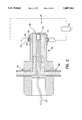
- FIG. 6is a side view of the center block of FIG. 5 showing the end cap of the device (not shown in FIG. 5) in exploded form with portions located within the body thereof shown in phantom-broken lines;
- FIG. 7is a view of the center block of FIG. 7, showing in phantom-broken lines some of the features shown in the cross-sectional view of FIG. 5;
- FIG. 8is a front view of the end cap of FIG. 5 (the side that abuts against the center block), showing an electrode used as a reference electrode;
- FIG. 9is a side view of the side caps of FIG. 5 (both side caps being identical) showing a portion that abuts against the center block of the system;
- FIG. 10is a schematic diagram of a detailed embodiment of an analyzer of the invention like that of FIG. 1, but using optical detection in place of electrochemical detecting.
- a first embodiment of the microflow analyzing apparatus 10 of the inventionis schematically illustrated.
- such apparatuscomprises a housing H which defines a sample supply chamber 26 and an analyte measurement chamber 30, such chambers being separated by a single semipermeable membrane 28. While schematically illustrated as being of similar sizes, chamber 30 is significantly smaller than chamber 30.
- a fluid sample 12 containing an analyte to be measuredis loaded into chamber 26 via an inlet line 24 and a chamber inlet 25. As the sample enters the sample supply chamber 26, predetermined components (analytes) having a specific size diffuse through the membrane and enter the measurement chamber 30 for interaction with a fluid reagent contained therein.
- the lattermay comprise either a simple carrier for the analytes being measured, or alternatively an enzyme solution which is adapted to react with the analytes to produce a detectable byproduct.
- the fluid reagentwhich is provided by a source 14, is loaded into measurement chamber 30 via a first inlet line 32, a mixing valve 36, a second inlet line 38 and a chamber inlet 40.
- a detector D located within chamber 30operates to either directly detect the analyte in the carrier solution, or to detect the reaction byproduct produced by the enzyme in the fluid reagent and the analyte passed by the membrane.
- an enzyme solution 14may be loaded through the enzyme inlet line 32 through the valve 36 and the second chamber inlet line 38 into the second chamber inlet 40 to be received in the second chamber 30.
- an enzyme solution 14may be loaded simultaneously with a fluid 17 which is loaded through a fluid inlet line 34 and mixed by the mixing valve 36 with the enzyme solution 14. Thereafter, the mixture is introduced through the second chamber inlet line 38 through the inlet 40 into the second chamber 30.
- the fluid 17can include one of several substances.
- the fluid 17may be a buffer solution which allows dilution of the enzyme solution 14 to specified levels.
- the enzyme solution 14may be highly concentrated, it may be diluted to a level designed to achieve optimized reaction time and product generation.
- the fluid 17may be: 1) a higher concentration of the enzyme in enzyme solution 14; or 2) an enzyme solution different from that of enzyme solution 14.
- the amount suppliedcan be varied through the mixing valve 36 to selectively adjust the enzyme concentration upwardly in the chamber 30 to achieve optimum reaction time and detectable product generation.
- the fluid 17is an enzyme different from that of the enzyme solution 14, it may be of the type, for example, designed to achieve a two-stage reaction wherein the enzyme solution 14 catalyzes a reaction to result in an intermediate byproduct.
- the fluid 17when the fluid 17 is a second enzyme, it acts on the intermediate byproduct which is then caused to react into a final by product which is detected in the chamber 30 by the signal detector 44.
- the signal detector 44is shown located in the second chamber 30, for example, immediately behind the membrane 28 which defines the second chamber 30.
- the signal detector 44is, for example, a signal detecting electrode, preferably of platinum, which when predetermined substances are present in the fluid within the second chamber 30, causes a current to flow from detector 44 through signal detecting electrode lead 52 in a complete circuit with a reference electrode 42.
- the reference electrode 42is typically located in the first chamber 26 and is connected through a reference electrode lead 50 to a signal analyzing unit 54.
- the signal analyzing unit 54serves to analyze the signal received and provides an output through an output device 56 which is representative of the amount of the measured component in the sample.
- the output device 56is conventional and well known to those of ordinary skill in the art.
- the signal analyzing unit 54 and the output device 56can be, respectively, a conventional personal computer with a monitor and a printer attached thereto.
- the computerthrough the operation of, e.g., conventional glucose analysis software of the type well known to those of ordinary skill in the art, analyzes the current flow from the reference lead 50 and the signal lead 52 to provide a representative output which is indicative of the presence and quantity of a measurable component, i.e., glucose, in the fluid in the chamber 30.
- a measurable componenti.e., glucose
- the reference electrode 42is shown disposed within the first chamber 26, it can also be disposed within the second chamber 30. As noted, the reference electrode 42 serves to complete the circuit with the signal detecting electrode 44 to detect the presence of the selected material within the second chamber 30.
- the fluid sample 12may then be discharged through a first chamber outlet 57 through a sample outlet line 59, through a sample outlet valve 61 and into waste chamber 86. Since some detectable product still remains in the second chamber 30 with enzyme therein, additional enzyme solution 14 is flowed through the chamber 30 to remove all of the detectable components, i.e., by flushing, from the second chamber 30 through an outlet 58.
- a compensating detector 46when the preferred embodiment is an electrode, which serves to measure signals caused by interfering substances within the fluid sample 12 in the chamber 26.
- the electrode 46can optionally have a membrane 28', like membrane 28, disposed around it as shown in dashed lines in FIG. 1. The reason for such an arrangement is to allow rapid removal of interfering substances from the surface of electrode 46 in preparation for the next sample.
- signalscan be caused by electrochemically active substances such as uric acid, ascorbic acid or acetaminophen present in a sample.
- the measurement of the signal caused by the interfering substancesis done with the sample which does not yet contain the electrochemically detectable byproduct of an analyte to be measured. While not necessary, if the compensating electrode 46 is employed, the interference signal is subtracted from the signal generated by the signal detecting electrode 44 to provide a true indication of the presence of a measurable component within the chamber 30. As in the case with the reference and signal detecting electrodes 42 and 44, if the compensating detector 46 is an electrode, it is also connected to the signal analyzing unit 54, in this case through compensating electrode lead 48, and the signal detected thereby which is indicative of interfering substances, is processed in a conventional manner by the signal analyzing unit 54 and reflected at the output device 56.
- the reference electrode 42 and/or the compensating electrode 46can be covered with membranes (not illustrated) of molecular weight cutoffs of about 10,000 g/m.
- This type of membraneprevents passage of molecules having molecular weights greater than about 10,000 g/m plus or minus known variances as apparent to those of ordinary skill in the art.
- membraneshaving lower molecular weight cutoffs can be employed, depending upon the specific analysis to be conducted.
- the signal detecting electrode 44is not subject to fouling by the larger molecular weight molecules because it is already protected by the membrane 28 which allows the detectable substances to pass through into the second chamber 30.
- FIG. 2An actual example of one configuration of the second chamber 30 of the system 10 of the invention is shown in FIG. 2.
- the membrane 28is held on the end of a projection 82 by means of an O-ring ring 88 received in a groove 90 at the end of the projection 82.
- Walls 84which partially define the chamber 26 fit and seal against O-ring 88 at a cut-out region 86 at the end thereof, for example, in a press-fit arrangement, to define the first chamber 26 on the other side of the membrane 28.
- Alternatives to the press-fit arrangementcan include such common variants as a threaded screw fit or other equivalent engagement structures.
- the signal detector 44i.e., a signal detecting electrode
- the signal detector 44is located within the second chamber 30 and is connected by means of the signal detecting electrode lead 52 to the signal analyzing unit 54, as is shown in FIG. 1.
- the electrodes employed for the signal detecting electrode 44, the reference electrode 40 and the compensating electrode 46, which are shown in FIG. 1,are preferably typical electrochemical signal electrodes, more specifically amperometric sensing electrodes, which are useful for the detection of hydrogen peroxide.
- Such electrodesmay include a platinum anode (signal detecting electrode 44) and a silver or a silver/silver chloride cathode (reference electrode 42), with 0.6 positive volts imposed on the platinum electrode.
- hydrogen peroxideundergoes catalysis to generate a current proportional to its concentration as follows:
- the current so measuredis used to calculate the concentration of the preselected analyte in the sample 12, i.e., glucose.
- the second chamber inlet 40 and a second chamber outlet 58 for enzyme solutionpreferably are nonporous tubes of conventional construction.
- the chamber 30is shown as being relatively small in size when compared to the first chamber 26 for the sample.
- the first chamber 26can be in the shape of a cup with the second chamber 30 defined by a projection into the cup (FIG. 2)
- the first chamber 26 volumecan be on the order of 500-1000 microliters with the second chamber 30 volume being on the order of about 1/10 to about 1/100 the volume of the first chamber 26.
- total volume flowing through the embodiment of FIGS. 5-9will be only about 90 microliters or less, with the volume flow through the first chambers 26a and 26c each making up about 25 microliters, and the volume of the second chamber 30 making up about 7 microliters or less of the total 90 microliters.
- the components from the sample 12, the carrier or enzyme solution 14 and the fluid 17are discharged through the second chamber outlet 58, through a second chamber outlet line 60 and through second chamber outlet valve 62a, in some cases directly into a waste container 64.
- the valve 62ais preferably a three-way valve capable of directing flows to the waste container 64, or into a recycling unit 66.
- the signal or detectable componentcan be flushed and diluted to non-detectable amounts, for example, as shown in FIG. 1, by passing the discharge from the second chamber 30 through the discharge valve 62a into a bypass line 68 leading optionally to a removal unit 70 arranged alone or in parallel to a recycling holding tank 78.
- a removal device 72serves to eliminate undesired components from the discharged carrier or enzyme solution 14 from the second chamber 30, and passes the carrier or enzyme solution 14 through valve 62d and recycle line 80 to the inlet valve 36, i.e., in this case a four-way valve, and back into the second chamber 30. This avoids the requirement of having to constantly feed fresh enzyme through line 32 thereby significantly reducing costs.
- such a removal unit 70is not necessary because the undesired components break down over time before recycling into the second chamber 30.
- any unitcan be used that filters out the undesired components.
- an immobilized catalase unitcan be employed to cause an enzymatic breakdown of the hydrogen peroxide to ensure that there is no measurable component present, i.e., that any hydrogen peroxide returned to the second chamber 30 is in amounts which are non-measurable by the system.
- the recycling holding tank 78in which the hydrogen peroxide can be reduced in concentration to non-detectable amounts.
- the various flowsare then controlled and directed by valves 62b and 62c, all of which make up a part of the enzyme recycling unit 66 of the embodiment of FIG. 1.
- the tank 78is made large enough to ensure that the measurable component becomes sufficiently diluted, therefore the concentration level is sufficiently low so that upon recycling into the second chamber 30 the amount of residual, measurable component remaining is insufficient to affect the detection or measurement being conducted in the second chamber 30.
- waste line 76permits discharge of the recycled enzyme through valve 62e into waste container 64. New enzyme can then be added to the system 10 through inlet line 32.
- FIG. 3An alternative physical embodiment of the analyzer 10 in accordance with the invention is better illustrated in FIG. 3, wherein like elements are numbered the same as in the previous embodiments.
- the fluid sample 12is initially mixed with the fluid 17 at the inlet valve 22, and the mixture is thereafter passed through the inlet line 24 and the first chamber inlet 25 into the chamber 26.
- the interaction of the fluid 17 with the fluid sample 12results in components of the fluid sample being carried by the carrier solution through means of a chemical or physical bond, or in an intermediate byproduct or final product form, i.e., a signal. Either one of the resulting product passes through the membrane 28 into the second chamber 30, to be detected by the signal detector 44.
- the carrier or enzyme 14is passed through the inlet line 32 through the valve 36, into inlet line 38 and through the inlet 40 into the chamber 30.
- the carrier or enzyme 14serves as a catalyst reactant with or as a carrier for the byproduct or signal which is introduced into the chamber 30.
- the intermediate productpasses through the membrane 28 reacts with reactant introduced into the chamber 30 or reacts in the presence of enzyme in the chamber 30, to result in a final product which is detected as the signal.
- the fluid in the second chamber 30may then simply be a carrier for the product from the first chamber 26.
- the second chamber 30is flushed by adding more carrier or enzyme solution 14 and discharging the initial contents through the second chamber outlet 58 through line 60 and second chamber outlet valve 62a into the waste chamber 64.
- this embodimentmay also have a recycling unit similar to the recycling unit 66 of FIG. 1.
- FIG. 4An alternative embodiment 10' in accordance with the invention is shown in FIG. 4.
- a sample 12 for a chemical assayis pre-stored as the fluid sample 12.
- a samplecan be plasma or serum which is then held as the fluid sample 12.
- the plasma or serummixes with an enzyme capable of catalyzing a reaction involving glucose as a substrate to yield hydrogen peroxide.
- the inlet valve 22is opened and the fluid sample 12 flows through the inlet line 24 and the first chamber inlet 25 into the first chamber 26.
- the hydrogen peroxide previously generated in the sample 12then passes through the membrane 28 into the fluid in the chamber 30 to be carried thereby and detected by the signal detecting electrode 44.
- a signalis passed through the leads 50 and 52, to the signal analyzing unit 54 (not shown in this figure), as previously described.
- the fluid in chamber 30, which is supplied through inlet 40 and discharged through outlet 58 in this embodimentneed not be enzyme and only needs to be a fluid capable of carrying the byproduct of the fluid sample 12, i.e., the hydrogen peroxide generated in the sample 12.
- the hydrogen peroxide detectedis indicative of the amount of an analyte in the blood sample, and depending upon the nature of the sample 12, it may be necessary to take into account the concentration of enzyme and time of holding of fluid sample 12.
- Alternative samplesmay be used to detect other components as will be readily apparent to those of ordinary skill in the art.
- the sample fluid 12can be discharged through the first chamber outlet 57 and the sample outlet line 59 by opening the sample outlet valve 61.
- a compensating electrode 46can also be provided to measure interfering substances and adjust for the measurements made by the electrodes 42 and 44.
- the fluidis preferably one of several carrier fluids, all capable of carrying in suspension or solution, the final detectable product, for example, any hydrogen peroxide generated in the fluid sample 12.
- the fluid sample 12is discharged through the first chamber outlet 57 and a new sample 12 is introduced through the first chamber inlet 25.
- the fluid in the chamber 30 having hydrogen peroxide thereinis discharged through the second chamber outlet 58 to remove any detectable hydrogen peroxide and the second chamber 30 is refilled through the second chamber inlet 40.
- the fluid in chamber 30can be one capable of causing a reaction of the substance in the sample 12 which is the first product of a reaction in the sample 12 and results in a third substance which is then detected in the chamber 30.
- the device of FIGS. 5-9takes advantage of the fact that electrochemical detection of specified components requires only very small amounts of fluid, i.e., liquid.
- the amount of liquid requiredis an amount sufficient to merely "wet" the surface of the electrodes.
- wetthe surface of the electrode is meant an amount sufficient to achieve electrochemically measurable activity which is accurately indicative of the amount of substance being measured.
- Such a “wetting”is all that is required in all embodiments of the invention.
- both the amount of enzyme or carrier fluid as well as the amount of sample required to practice the inventioncan be substantially reduced because the device of FIGS. 5-9 can be made of a substantially smaller size than the other embodiments described herein.
- FIG. 5shows the alternative embodiment of the invention in side cross-section, exploded view.
- a fluid sampleis introduced through the first chamber inlet 25 to pass into multiple miniature first chambers 26a, 26b (FIG. 6), and 26c.
- the flow of the fluid sampleis into chamber 26a, and passes through membrane 28' into contact with the compensating electrode 46 which is located in a third chamber 26a' on the other side of membrane 28'.
- a buffer solutionis typically located which serves to carry interfering substances to be detected by the compensating electrode 46.
- the first chambers 26a and 26care defined by two side blocks 102 which abut against center block 100 with O-rings 29' fitting in a corresponding groove 104' in each of the side blocks 102 to seal the chambers 26a and 26c.
- First chamber 26ais further defined by membrane 28' which also serves to define third chamber 26a'.
- From the chamber 26athe sample continues through flow path 27, as better illustrated by FIGS. 7 and 8, into a second chamber 26b which, as shown in FIG. 6, is defined by end block 116 abutting against the center block 100.
- an O-ring(not shown in this case) is seated within groove 124 when the system is assembled to seal second chamber 26b.
- the fluid samplethen passes through chamber 26b in contact with reference electrode 42 for completing a circuit with a detecting signal electrode 44 discussed hereafter.
- the fluid samplecontinues through the flow path 27 into the chamber 26c and into contact with the membrane 28 which defines the second chamber 30.
- the O-ring 29along with the O-ring 29' engage in their corresponding grooves 104 and 104' when the device is assembled, and serve to hold the membrane 28 in position to define the second chamber 30.
- the measurable component in the samplethen passes through the membrane 28 to be carried by a carrier solution in the chamber 30 and detected by the signal detecting electrode 44, or to react in the presence of an enzyme in the chamber 30 to result in a product detectable by the signal detecting electrode 44.
- the entire assemblyis held together by screws which fit respectively in and through openings 118, 120, 122 and 126 as shown in FIGS. 6 and 9.
- the enzyme or carrier solution with the detectable productcan then be flushed from the system by adding carrier or enzyme through the inlet 40 into the second chamber 30 thereby discharging the spent carrier or enzyme through the outlet 58.
- the systemcan be flushed and a baseline value set for the compensating electrode 46 and the reference electrode 42.
- the membrane 28'defines the third chamber 26a' in which the enzyme or carrier solution with the detectable product are located after conducting a measurement.
- the systemis flushed and a baseline value set for the compensating electrode 46 and the reference electrode 42 by flowing a buffer solution through the inlet 25 and the outlet 57 and by also introducing a buffer solution through inlet 112 which is passed through third chamber 26a' and out discharge 114 to flush interfering substances from the third chamber 26a'.
- temperature controlcan be effected with the device of FIGS. 5-9 by introducing hot or cold liquid, e.g., water, into an annular ring, i.e., a water jacket, thereof.
- hot or cold liquide.g., water
- annular ringi.e., a water jacket
- the wateris introduced through an inlet 106 from which it passes into annular rings 108 which are interconnected by a passageway 110.
- the watersurrounds the chambers 26a and 26c to provide heating or cooling as well as to heat or cool the entire assembly 10.
- the O-rings 29 and 29'also serve to seal the annular rings 108 by fitting into the grooves 104 and 104' to prevent leakage of liquid therefrom. As the liquid circulates it is then discharged through an outlet 128.
- the fluid samplein general can be a multi-component mixture which is made up of a liquid, and typically, at least one analyte which is distinct from the liquid, and is carried therein.
- the liquid of the fluid samplecan be, for example, a single-phase system such as a single liquid, or a solution of two or more miscible liquids, or a multi-phase system such as an emulsion.
- the analyte in the samplecan be, for example, a chemical compound such as a carbohydrate, a lipid, or a protein.
- the fluid sampletypically can also include suspended cells or cellular material, for example, blood or lysates, solid particles such as food pulp, or dissolved solids such as sugars or salts.
- a preferred use of the device in accordance with the inventionis with biological or physiological fluids, such as blood or a blood portion such as plasma.
- biological or physiological fluidswhich can have quantitative measurements of components thereof measured with the device of the invention include urine, saliva, cell lysates, tissue cultures and culture media.
- biological or physiological fluidsinclude consumable liquids such as fruit juices, soft drinks, milk, as well as non-consumable liquids, typically, liquid product streams such as treated waste water.
- Typical enzyme and other solutions employed in the apparatus and method of the inventioninclude a liquid carrier, which is conventional and well known to those of ordinary skill in the art, such as water, or a saline solution, and with the enzyme system including one or more enzymes which are capable of interacting with the preselected analyte to ultimately produce a byproduct which is detected in the device and method of the invention.
- a liquid carrierwhich is conventional and well known to those of ordinary skill in the art, such as water, or a saline solution
- the enzyme systemincluding one or more enzymes which are capable of interacting with the preselected analyte to ultimately produce a byproduct which is detected in the device and method of the invention.
- the byproductwill be described hereafter as being a detectable signal.
- the enzyme systemis made up of a single enzyme
- the enzymeinteracts with the preselected analyte to produce the detectable signal directly.
- the enzyme systemcan also include cofactors and/or additional substrates necessary for production of detectable signal.
- the enzyme systemcan include two or more enzymes characterized by causing coupled enzymatic reactions which sequentially or simultaneously result in the byproduct which is the detectable signal.
- the fluid 17is an enzyme and the carrier or enzyme solution 14 is a different enzyme.
- the first enzymeproduces an intermediate byproduct through reaction with the preselected analyte to produce the intermediate byproduct.
- the byproductthen interacts with the second enzyme as a substrate or cofactor to produce, in turn, the byproduct which is the detectable signal.
- the detectable productis already present in the sample because it was originally present or because it was generated elsewhere, and need not be generated. When this occurs, no enzyme is necessary for the measurement chamber 30 and only a carrier solution such as a buffer need be provided to carry the detectable substance.
- the detectable signal in practicing the inventiondepends on the nature of the analyte and the selected enzyme system.
- the signalcan be an electrochemically detectable product, such as hydrogen peroxide, which is detectable by, for example, platinum electrodes.
- the signalcan be an optical signal such as a color change or a fluorescent signal, i.e. a photon emission, as will be readily apparent to those of ordinary skill in the art.
- an optical signalsuch as a color change or a fluorescent signal, i.e. a photon emission
- the optical and fluorescent signal detectioncan be effected by reacting hydrogen peroxide with additional compounds giving rise to chromogens or fluorogens which are detectable by fluorescent techniques.
- color changeis a reaction where the amount of analyte present is proportional to the intensity of color change as follows: ##STR2##
- FIG. 10An optical detection system can be implemented as shown in FIG. 10, which is similar to FIG. 1.
- the electrodes 42 and 46, and their associated componentsare eliminated.
- a color, fluorescence, or luminescence detector 44'replaces electrode 44, and is connected through lead 52' to the signal analyzing unit 54.
- detector 44'is shown within the chamber 30, it will be appreciated that other equivalent configurations can be employed.
- detector 44'located outside of the wall of chamber 30. In such a construction the wall of chamber 30 can be transparent to allow detection to occur.
- the particular enzyme system to be employedit is important to consider stability, the presence of one or more enzymes in the enzyme system, or one or more intermediate substrates therefor in the fluid sample. Other factors include fluid sample properties, including pH, enzyme rate profiles and costs.
- glucose oxidaseAn example of a single-enzyme system is glucose oxidase.
- glucose oxidaseinteracts with glucose (the preselected analyte) which passes through the membrane into the measurement chamber and generates hydrogen peroxide as the detectable signal.
- the hydrogen peroxide thus generatedcan then be directly detected by an electrochemical signal detector, i.e., an electrode pair, as discussed previously.
- An example of a useful multi-enzyme systemis the lipase/glycerol kinase/glycerol-1-phosphate oxidase system.
- Lipaseinteracts with triglycerides, the preselected analyte, to generate glycerol.
- Glycerolin turn serves as a substrate for glycerol kinase.
- Interaction of glycerol and glycerol kinase, together with an ATP moleculeyields glycerol-1-phosphate, which serves in turn as the substrate for glycerol-1-phosphate oxidase. This final enzymatic reaction affords hydrogen peroxide as the detectable signal.
- amperometrically detectable systemsare exemplary enzyme systems which generate optically detectable signals and include the glucose oxidase/horseradish peroxidase system.
- glucose oxidase/horseradish peroxidase systemthe hydrogen peroxide generated by glucose oxidase upon interaction with glucose, as described above, is subsequently acted upon by horseradish peroxidase.
- horseradish peroxidaseIn combination with a suitable additional peroxidase substrate, the horseradish peroxidase produces a color change as the detectable signal.
- the suitable additional peroxidase substratesinclude ortho-phenylenediamine (OPD), 2,2-azino-di-(3-ethylbenzthiazoline sulfonic acid-6) diammonium salt (ABTS) and 3,3',5,5'-tetramethylbenzidine (TMB). These and other suitable peroxidase substrates are described in Voller et al., Manual of Clinical Laboratory Immunology, Chapter 17.
- a dialysis membranewhich is permeable to a spectrum of test molecules is preferred. Selection can be accomplished by studying the actual dialysis rates of solutes of known size under standard conditions. This selection technique is conventional and well known to those of ordinary skill in the art.
- the followingare specific examples of the use of the device to detect certain substances in a fluid sample.
- the detection systemconsisted of a platinum anode and a silver or a silver/silver chloride cathode, which in the case of the embodiment of the invention used in this example, had 0.6 volts imposed across the electrodes.
- the platinum electrodeanode
- the following reactionthen took place to result in a current proportional to the concentration of glucose:
- the detecting electrode in the second chamberhad glucose oxidase enzyme microflowed in front of it on one side of the membrane.
- a plasma or whole blood solutionwas prepared by dilution with PBS in a ratio of 1:20.
- the diluted plasma and the whole blood, for each test respectively,was introduced into the first chamber 26 and the detecting electrode 44 detected a signal proportional to the amount of glucose in the plasma and the whole blood, respectively, as shown in Table 1 below.
- Portions of the same sampleswere also tested using the above-referenced YSI 2300 STAT glucose analyzer following the conventional instructions outlined for its use. The results of all the tests are outlined below in Table I.
- both the system of the invention and the YSI devicefunction effectively to measure glucose in a biological sample.
- recalibrationwas required every fifteen minutes, or every five tests, whichever occurred first.
- this requirementwas avoided by shorting the electrodes after each measurement, for example, in a manner similar to that illustrated in FIG. 1.
- a detecting electrode in second chamber 30was microflowed with glucose oxidase and the background electrode was microflowed with a diluent, i.e., PBS, to establish a background signal level.
- PBSa diluent
- a portion of each samplewas respectively introduced into first chamber 26 of 25 ⁇ l of the fluid diluted with 475 ⁇ l of buffer solution.
- the compensating electrodedetected no background signal.
- Portions of the sampleswere also tested with the YSI 2300 STAT glucose analyzer following the procedures outlined therefor. The results obtained are shown in Table II below.
Landscapes
- Chemical & Material Sciences (AREA)
- Health & Medical Sciences (AREA)
- Life Sciences & Earth Sciences (AREA)
- Organic Chemistry (AREA)
- Zoology (AREA)
- Engineering & Computer Science (AREA)
- Proteomics, Peptides & Aminoacids (AREA)
- Wood Science & Technology (AREA)
- Physics & Mathematics (AREA)
- General Health & Medical Sciences (AREA)
- Biochemistry (AREA)
- Immunology (AREA)
- Molecular Biology (AREA)
- Analytical Chemistry (AREA)
- Microbiology (AREA)
- Biotechnology (AREA)
- Bioinformatics & Cheminformatics (AREA)
- General Engineering & Computer Science (AREA)
- Biophysics (AREA)
- Genetics & Genomics (AREA)
- Hematology (AREA)
- Emergency Medicine (AREA)
- Chemical Kinetics & Catalysis (AREA)
- Electrochemistry (AREA)
- General Physics & Mathematics (AREA)
- Pathology (AREA)
- Measuring Or Testing Involving Enzymes Or Micro-Organisms (AREA)
- Apparatus Associated With Microorganisms And Enzymes (AREA)
Abstract
Description
H.sub.2 O.sub.2 →H.sub.2 O+1/2O.sub.2 +e.sup.-
H.sub.2 O.sub.2 →H.sub.2 O+1/2O.sub.2 +e--
TABLE I ______________________________________ (Glucose (mg/dL) NO. OF FIG. 5 SAMPLE TESTS SENSOR YSI ______________________________________Plasma 1 3 84 81 Plasma 2 3 61 64 Plasma 3 3 81 81Whole Blood 1 2 70 68 Whole Blood 2 3 53 53 Whole Blood 3 3 67 67 ______________________________________
TABLE II ______________________________________ Glucose (mg/dL) SAMPLE SENSOR YSI ______________________________________ Orange Juice 209 211 Coca-Cola 407 415 Diet Coke 11 0 Grapefruit Juice 408 420 Hawaiian Punch 516 517 Peach Snapple 507 522 ______________________________________
Claims (14)
Priority Applications (4)
| Application Number | Priority Date | Filing Date | Title |
|---|---|---|---|
| US08/410,997US5607565A (en) | 1995-03-27 | 1995-03-27 | Apparatus for measuring analytes in a fluid sample |
| PCT/US1996/004113WO1996030751A1 (en) | 1995-03-27 | 1996-03-26 | Apparatus for measuring analytes in a fluid sample |
| JP8529593AJPH10501425A (en) | 1995-03-27 | 1996-03-26 | Measuring device for analytes in liquid samples |
| EP96910565AEP0760946A1 (en) | 1995-03-27 | 1996-03-26 | Apparatus for measuring analytes in a fluid sample |
Applications Claiming Priority (1)
| Application Number | Priority Date | Filing Date | Title |
|---|---|---|---|
| US08/410,997US5607565A (en) | 1995-03-27 | 1995-03-27 | Apparatus for measuring analytes in a fluid sample |
Publications (1)
| Publication Number | Publication Date |
|---|---|
| US5607565Atrue US5607565A (en) | 1997-03-04 |
Family
ID=23627128
Family Applications (1)
| Application Number | Title | Priority Date | Filing Date |
|---|---|---|---|
| US08/410,997Expired - Fee RelatedUS5607565A (en) | 1995-03-27 | 1995-03-27 | Apparatus for measuring analytes in a fluid sample |
Country Status (4)
| Country | Link |
|---|---|
| US (1) | US5607565A (en) |
| EP (1) | EP0760946A1 (en) |
| JP (1) | JPH10501425A (en) |
| WO (1) | WO1996030751A1 (en) |
Cited By (86)
| Publication number | Priority date | Publication date | Assignee | Title |
|---|---|---|---|---|
| US5843691A (en)* | 1993-05-15 | 1998-12-01 | Lifescan, Inc. | Visually-readable reagent test strip |
| WO1999046585A1 (en)* | 1998-03-12 | 1999-09-16 | Usf Filtration And Separations Group Inc. | Heated electrochemical cell |
| DE19813870A1 (en)* | 1998-03-29 | 1999-09-30 | Mario Strobl | Non-immobilized bio-electrode detector |
| US5962215A (en)* | 1996-04-05 | 1999-10-05 | Mercury Diagnostics, Inc. | Methods for testing the concentration of an analyte in a body fluid |
| US6077660A (en)* | 1998-06-10 | 2000-06-20 | Abbott Laboratories | Diagnostic assay requiring a small sample of biological fluid |
| US6085576A (en)* | 1998-03-20 | 2000-07-11 | Cyrano Sciences, Inc. | Handheld sensing apparatus |
| AU743852B2 (en)* | 1998-03-12 | 2002-02-07 | Lifescan, Inc. | Heated electrochemical cell |
| US20020106710A1 (en)* | 1989-08-28 | 2002-08-08 | Tuohy Deborah P. | Method of making a test strip for determining analyte concentration over a broad range of sample volumes |
| US20020130043A1 (en)* | 1998-03-12 | 2002-09-19 | Alastair Hodges | Heated electrochemical cell |
| US6475360B1 (en) | 1998-03-12 | 2002-11-05 | Lifescan, Inc. | Heated electrochemical cell |
| US6475800B1 (en) | 1999-07-22 | 2002-11-05 | Instrumentation Metrics, Inc. | Intra-serum and intra-gel for modeling human skin tissue |
| US20020168688A1 (en)* | 1996-06-28 | 2002-11-14 | Caliper Technologies Corp | High throughput screening assay systems in microscale fluidic devices |
| US20020176072A1 (en)* | 1999-10-05 | 2002-11-28 | Stefan Beseki | Device and method for controlling the quality of microdroplets deposited on a substrate |
| US6558960B1 (en) | 1996-06-28 | 2003-05-06 | Caliper Technologies Corp. | High throughput screening assay systems in microscale fluidic devices |
| US20030228681A1 (en)* | 2002-04-05 | 2003-12-11 | Powerzyme, Inc. | Analyte sensor |
| WO2003082469A3 (en)* | 2002-04-03 | 2003-12-24 | C Cit Ag | Device and method for carrying out and continuously monitoring chemical and/or biological reactions |
| US20040065562A1 (en)* | 2001-10-10 | 2004-04-08 | Alastair Hodges | Electrochemical cell |
| US6723500B2 (en) | 2001-12-05 | 2004-04-20 | Lifescan, Inc. | Test strips having reaction zones and channels defined by a thermally transferred hydrophobic barrier |
| US20040206636A1 (en)* | 1995-11-16 | 2004-10-21 | Hodges Alastair Mcindoe | Electrochemical cell |
| AU779350B2 (en)* | 1998-03-12 | 2005-01-20 | Lifescan, Inc. | Heated electrochemical cell |
| US20050051427A1 (en)* | 2003-07-23 | 2005-03-10 | Brauker James H. | Rolled electrode array and its method for manufacture |
| US20050051440A1 (en)* | 2003-07-25 | 2005-03-10 | Simpson Peter C. | Electrochemical sensors including electrode systems with increased oxygen generation |
| US20050077176A1 (en)* | 1995-06-19 | 2005-04-14 | Lifescan, Inc. | Electrochemical cell |
| US20050103625A1 (en)* | 2001-07-27 | 2005-05-19 | Rathbun Rhodes | Sensor head for use with implantable devices |
| US20050143635A1 (en)* | 2003-12-05 | 2005-06-30 | Kamath Apurv U. | Calibration techniques for a continuous analyte sensor |
| US20050142586A1 (en)* | 2003-11-26 | 2005-06-30 | Hedberg Herbert M. | Measuring enzymatic activity |
| US20050177036A1 (en)* | 1997-03-04 | 2005-08-11 | Shults Mark C. | Device and method for determining analyte levels |
| US20050181012A1 (en)* | 2004-01-12 | 2005-08-18 | Sean Saint | Composite material for implantable device |
| US20050182451A1 (en)* | 2004-01-12 | 2005-08-18 | Adam Griffin | Implantable device with improved radio frequency capabilities |
| US20050245799A1 (en)* | 2004-05-03 | 2005-11-03 | Dexcom, Inc. | Implantable analyte sensor |
| RU2267120C2 (en)* | 2000-07-14 | 2005-12-27 | Лайфскен, Инк. | Electrochemical mode of measuring of speed of chemical reactions |
| US20060000722A1 (en)* | 1996-06-28 | 2006-01-05 | Caliper Life Sciences, Inc. | High throughput screening assay systems in microscale fluidic devices |
| US20060015020A1 (en)* | 2004-07-06 | 2006-01-19 | Dexcom, Inc. | Systems and methods for manufacture of an analyte-measuring device including a membrane system |
| US20060016700A1 (en)* | 2004-07-13 | 2006-01-26 | Dexcom, Inc. | Transcutaneous analyte sensor |
| US20060200022A1 (en)* | 2003-04-04 | 2006-09-07 | Brauker James H | Optimized sensor geometry for an implantable glucose sensor |
| US20060222566A1 (en)* | 2003-08-01 | 2006-10-05 | Brauker James H | Transcutaneous analyte sensor |
| US20060252027A1 (en)* | 2005-05-05 | 2006-11-09 | Petisce James R | Cellulosic-based resistance domain for an analyte sensor |
| US20070032718A1 (en)* | 1997-03-04 | 2007-02-08 | Shults Mark C | Device and method for determining analyte levels |
| EP1774305A1 (en)* | 2004-07-08 | 2007-04-18 | Chemel AB | Sire flow detector |
| US20070173709A1 (en)* | 2005-04-08 | 2007-07-26 | Petisce James R | Membranes for an analyte sensor |
| US20080030738A1 (en)* | 1997-02-04 | 2008-02-07 | Biacore Ab | Analytical method and apparatus |
| US20090030641A1 (en)* | 2007-10-23 | 2009-01-29 | Edwards Lifesciences Corporation | Monitoring and compensating for temperature-related error in an electrochemical sensor |
| US20090118604A1 (en)* | 2007-11-02 | 2009-05-07 | Edwards Lifesciences Corporation | Analyte monitoring system having back-up power source for use in either transport of the system or primary power loss |
| US20090143658A1 (en)* | 2006-02-27 | 2009-06-04 | Edwards Lifesciences Corporation | Analyte sensor |
| US20090188811A1 (en)* | 2007-11-28 | 2009-07-30 | Edwards Lifesciences Corporation | Preparation and maintenance of sensors |
| US20090191582A1 (en)* | 2006-02-23 | 2009-07-30 | Mologic Ltd | Enzyme detection |
| US7651596B2 (en) | 2005-04-08 | 2010-01-26 | Dexcom, Inc. | Cellulosic-based interference domain for an analyte sensor |
| US7657297B2 (en) | 2004-05-03 | 2010-02-02 | Dexcom, Inc. | Implantable analyte sensor |
| US20100072062A1 (en)* | 2008-05-05 | 2010-03-25 | Edwards Lifesciences Corporation | Membrane For Use With Amperometric Sensors |
| US20100089769A1 (en)* | 2008-10-06 | 2010-04-15 | Sony Corporation | Method of derivatising an analyte for subsequent detection through a nucleic acid based sensor |
| US20100108509A1 (en)* | 2008-10-31 | 2010-05-06 | Edwards Lifesciences Corporation | Analyte Sensor with Non-Working Electrode Layer |
| US20100243477A1 (en)* | 2008-08-27 | 2010-09-30 | Edwards Lifesciences Corporation | Analyte Sensor |
| US20100304494A1 (en)* | 2009-05-29 | 2010-12-02 | Ecolab Inc. | Microflow analytical system |
| US7860544B2 (en) | 1998-04-30 | 2010-12-28 | Abbott Diabetes Care Inc. | Analyte monitoring device and methods of use |
| US7885697B2 (en) | 2004-07-13 | 2011-02-08 | Dexcom, Inc. | Transcutaneous analyte sensor |
| US20110054284A1 (en)* | 2009-08-28 | 2011-03-03 | Edwards Lifesciences Corporation | Anti-Coagulant Calibrant Infusion Fluid Source |
| US7920907B2 (en) | 2006-06-07 | 2011-04-05 | Abbott Diabetes Care Inc. | Analyte monitoring system and method |
| US7976778B2 (en) | 2001-04-02 | 2011-07-12 | Abbott Diabetes Care Inc. | Blood glucose tracking apparatus |
| USRE42567E1 (en) | 1995-11-16 | 2011-07-26 | Lifescan, Inc. | Electrochemical cell |
| US8052601B2 (en) | 2003-08-01 | 2011-11-08 | Dexcom, Inc. | System and methods for processing analyte sensor data |
| US20110318096A1 (en)* | 2009-03-04 | 2011-12-29 | Peugeot Citroen Automobiles Sa | Dual Material Device, Casing and Vehicle Provided With Said Device, and Method for Making Said Device |
| US8160669B2 (en) | 2003-08-01 | 2012-04-17 | Dexcom, Inc. | Transcutaneous analyte sensor |
| USRE43399E1 (en) | 2003-07-25 | 2012-05-22 | Dexcom, Inc. | Electrode systems for electrochemical sensors |
| US8275437B2 (en) | 2003-08-01 | 2012-09-25 | Dexcom, Inc. | Transcutaneous analyte sensor |
| US8287454B2 (en) | 1998-04-30 | 2012-10-16 | Abbott Diabetes Care Inc. | Analyte monitoring device and methods of use |
| US8346337B2 (en) | 1998-04-30 | 2013-01-01 | Abbott Diabetes Care Inc. | Analyte monitoring device and methods of use |
| EP1787110A4 (en)* | 2004-08-25 | 2013-03-13 | Chemel Ab | Calibratable flow detector |
| US8465425B2 (en) | 1998-04-30 | 2013-06-18 | Abbott Diabetes Care Inc. | Analyte monitoring device and methods of use |
| US8527026B2 (en) | 1997-03-04 | 2013-09-03 | Dexcom, Inc. | Device and method for determining analyte levels |
| US8612159B2 (en) | 1998-04-30 | 2013-12-17 | Abbott Diabetes Care Inc. | Analyte monitoring device and methods of use |
| US8622905B2 (en) | 2003-08-01 | 2014-01-07 | Dexcom, Inc. | System and methods for processing analyte sensor data |
| US8652043B2 (en) | 2001-01-02 | 2014-02-18 | Abbott Diabetes Care Inc. | Analyte monitoring device and methods of use |
| US8688188B2 (en) | 1998-04-30 | 2014-04-01 | Abbott Diabetes Care Inc. | Analyte monitoring device and methods of use |
| US8744546B2 (en) | 2005-05-05 | 2014-06-03 | Dexcom, Inc. | Cellulosic-based resistance domain for an analyte sensor |
| US8792955B2 (en) | 2004-05-03 | 2014-07-29 | Dexcom, Inc. | Transcutaneous analyte sensor |
| US8974386B2 (en) | 1998-04-30 | 2015-03-10 | Abbott Diabetes Care Inc. | Analyte monitoring device and methods of use |
| US9066695B2 (en) | 1998-04-30 | 2015-06-30 | Abbott Diabetes Care Inc. | Analyte monitoring device and methods of use |
| US9986942B2 (en) | 2004-07-13 | 2018-06-05 | Dexcom, Inc. | Analyte sensor |
| US10610136B2 (en) | 2005-03-10 | 2020-04-07 | Dexcom, Inc. | System and methods for processing analyte sensor data for sensor calibration |
| US10813577B2 (en) | 2005-06-21 | 2020-10-27 | Dexcom, Inc. | Analyte sensor |
| US10962525B2 (en)* | 2016-11-07 | 2021-03-30 | Sorbonne Universite | Process for characterizing a blood sample |
| US11399745B2 (en) | 2006-10-04 | 2022-08-02 | Dexcom, Inc. | Dual electrode system for a continuous analyte sensor |
| US11432772B2 (en) | 2006-08-02 | 2022-09-06 | Dexcom, Inc. | Systems and methods for replacing signal artifacts in a glucose sensor data stream |
| US11559260B2 (en) | 2003-08-22 | 2023-01-24 | Dexcom, Inc. | Systems and methods for processing analyte sensor data |
| US11589823B2 (en) | 2003-08-22 | 2023-02-28 | Dexcom, Inc. | Systems and methods for replacing signal artifacts in a glucose sensor data stream |
| US11633133B2 (en) | 2003-12-05 | 2023-04-25 | Dexcom, Inc. | Dual electrode system for a continuous analyte sensor |
Families Citing this family (5)
| Publication number | Priority date | Publication date | Assignee | Title |
|---|---|---|---|---|
| JP4581128B2 (en)* | 2005-07-20 | 2010-11-17 | 独立行政法人産業技術総合研究所 | Enzyme immunoassay method and enzyme immunosensor therefor |
| GB2435511A (en) | 2006-02-23 | 2007-08-29 | Mologic Ltd | Protease detection |
| GB2435512A (en) | 2006-02-23 | 2007-08-29 | Mologic Ltd | A binding assay and assay device |
| JP5366432B2 (en)* | 2008-05-09 | 2013-12-11 | 株式会社船井電機新応用技術研究所 | Gas detection system |
| DE102017011263B3 (en)* | 2017-12-06 | 2019-05-02 | Sartorius Stedim Biotech Gmbh | Apparatus and method for examining a medium |
Citations (13)
| Publication number | Priority date | Publication date | Assignee | Title |
|---|---|---|---|---|
| US3539455A (en)* | 1965-10-08 | 1970-11-10 | Leland C Clark Jr | Membrane polarographic electrode system and method with electrochemical compensation |
| US3839153A (en)* | 1970-12-28 | 1974-10-01 | Akzona Inc | Process for the detection and determination of specific binding proteins and their corresponding bindable substances |
| US3979274A (en)* | 1975-09-24 | 1976-09-07 | The Yellow Springs Instrument Company, Inc. | Membrane for enzyme electrodes |
| US4040908A (en)* | 1976-03-12 | 1977-08-09 | Children's Hospital Medical Center | Polarographic analysis of cholesterol and other macromolecular substances |
| GB2029013A (en)* | 1978-06-29 | 1980-03-12 | Fresenius Chem Pharm Ind | A method of and a device for chemical analysis |
| US4342739A (en)* | 1979-01-09 | 1982-08-03 | Fuji Photo Film Co., Ltd. | Novel material for immunological assay of biochemical components and a process for the determination of said components |
| US4483928A (en)* | 1981-09-07 | 1984-11-20 | Fuji Photo Film Co., Ltd. | Microcapsules sensitized with antibody and a method for measurement of lymphocyte using the same based on cell-mediated immunity |
| WO1985002017A1 (en)* | 1983-11-03 | 1985-05-09 | Sven Olof Enfors | Sensor for chemical analysis |
| WO1986007150A1 (en)* | 1985-05-21 | 1986-12-04 | Brian John Bellhouse | Apparatus for testing liquids |
| US4985125A (en)* | 1988-01-08 | 1991-01-15 | Taiyo Fishery Co., Ltd. | Method for detecting meat freshness using a biosensor |
| WO1992000515A1 (en)* | 1990-06-27 | 1992-01-09 | Fiberchem, Inc. | Reservoir chemical sensors with optional removable reservoir cells |
| US5352348A (en)* | 1987-04-09 | 1994-10-04 | Nova Biomedical Corporation | Method of using enzyme electrode |
| US5429726A (en)* | 1993-04-30 | 1995-07-04 | The Yellow Springs Instrument Company, Inc. | Methods for reducing level of interferants in biosensor systems and solutions used in these methods |
- 1995
- 1995-03-27USUS08/410,997patent/US5607565A/ennot_activeExpired - Fee Related
- 1996
- 1996-03-26EPEP96910565Apatent/EP0760946A1/ennot_activeWithdrawn
- 1996-03-26WOPCT/US1996/004113patent/WO1996030751A1/ennot_activeApplication Discontinuation
- 1996-03-26JPJP8529593Apatent/JPH10501425A/ennot_activeCeased
Patent Citations (13)
| Publication number | Priority date | Publication date | Assignee | Title |
|---|---|---|---|---|
| US3539455A (en)* | 1965-10-08 | 1970-11-10 | Leland C Clark Jr | Membrane polarographic electrode system and method with electrochemical compensation |
| US3839153A (en)* | 1970-12-28 | 1974-10-01 | Akzona Inc | Process for the detection and determination of specific binding proteins and their corresponding bindable substances |
| US3979274A (en)* | 1975-09-24 | 1976-09-07 | The Yellow Springs Instrument Company, Inc. | Membrane for enzyme electrodes |
| US4040908A (en)* | 1976-03-12 | 1977-08-09 | Children's Hospital Medical Center | Polarographic analysis of cholesterol and other macromolecular substances |
| GB2029013A (en)* | 1978-06-29 | 1980-03-12 | Fresenius Chem Pharm Ind | A method of and a device for chemical analysis |
| US4342739A (en)* | 1979-01-09 | 1982-08-03 | Fuji Photo Film Co., Ltd. | Novel material for immunological assay of biochemical components and a process for the determination of said components |
| US4483928A (en)* | 1981-09-07 | 1984-11-20 | Fuji Photo Film Co., Ltd. | Microcapsules sensitized with antibody and a method for measurement of lymphocyte using the same based on cell-mediated immunity |
| WO1985002017A1 (en)* | 1983-11-03 | 1985-05-09 | Sven Olof Enfors | Sensor for chemical analysis |
| WO1986007150A1 (en)* | 1985-05-21 | 1986-12-04 | Brian John Bellhouse | Apparatus for testing liquids |
| US5352348A (en)* | 1987-04-09 | 1994-10-04 | Nova Biomedical Corporation | Method of using enzyme electrode |
| US4985125A (en)* | 1988-01-08 | 1991-01-15 | Taiyo Fishery Co., Ltd. | Method for detecting meat freshness using a biosensor |
| WO1992000515A1 (en)* | 1990-06-27 | 1992-01-09 | Fiberchem, Inc. | Reservoir chemical sensors with optional removable reservoir cells |
| US5429726A (en)* | 1993-04-30 | 1995-07-04 | The Yellow Springs Instrument Company, Inc. | Methods for reducing level of interferants in biosensor systems and solutions used in these methods |
Non-Patent Citations (2)
| Title |
|---|
| YSI Model 2300 STAT Glucose & L Lactate Analyzer Operations Manual ; Yellow Springs Instrument Co., Inc.; pp. i iii, 2.1 2.8, 5.1 5.4, 6.3 6.4.* |
| YSI Model 2300 STAT Glucose & L-Lactate Analyzer Operations Manual; Yellow Springs Instrument Co., Inc.; pp. i-iii, 2.1-2.8, 5.1-5.4, 6.3-6.4. |
Cited By (276)
| Publication number | Priority date | Publication date | Assignee | Title |
|---|---|---|---|---|
| US20020106710A1 (en)* | 1989-08-28 | 2002-08-08 | Tuohy Deborah P. | Method of making a test strip for determining analyte concentration over a broad range of sample volumes |
| US6949221B2 (en) | 1989-08-28 | 2005-09-27 | Lifescan, Inc. | Method of making a test strip for determining analyte concentration over a broad range of sample volumes |
| US6986869B2 (en) | 1989-08-28 | 2006-01-17 | Lifescan, Inc. | Test strip for measuring analyte concentration over a broad range of sample volume |
| US20020106711A1 (en)* | 1989-08-28 | 2002-08-08 | Tuohy Deborah P. | Test strip for measuring analyte concentration over a broad range of sample volume |
| US5843691A (en)* | 1993-05-15 | 1998-12-01 | Lifescan, Inc. | Visually-readable reagent test strip |
| US20100078324A1 (en)* | 1995-06-19 | 2010-04-01 | Lifescan, Inc. | Electrochemical cell |
| US7608175B2 (en) | 1995-06-19 | 2009-10-27 | Lifescan, Inc. | Electrochemical cell |
| US20050077176A1 (en)* | 1995-06-19 | 2005-04-14 | Lifescan, Inc. | Electrochemical cell |
| US20100084288A1 (en)* | 1995-06-19 | 2010-04-08 | Lifescan, Inc. | Electrochemical Cell |
| US7604722B2 (en) | 1995-06-19 | 2009-10-20 | Lifescan, Inc. | Electrochemical cell |
| US8075760B2 (en) | 1995-06-19 | 2011-12-13 | Lifescan, Inc. | Electrochemical cell |
| US20100192369A1 (en)* | 1995-06-19 | 2010-08-05 | Lifescan, Inc. | Electrochemical Cell |
| USRE44330E1 (en) | 1995-06-19 | 2013-07-02 | Lifescan Inc. | Electrochemical cell |
| US8101056B2 (en) | 1995-06-19 | 2012-01-24 | Lifescan, Inc. | Electrochemical cell |
| US8597480B2 (en) | 1995-06-19 | 2013-12-03 | Lifescan, Inc. | Electrochemical cell |
| US20040206636A1 (en)* | 1995-11-16 | 2004-10-21 | Hodges Alastair Mcindoe | Electrochemical cell |
| US7431814B2 (en) | 1995-11-16 | 2008-10-07 | Lifescan, Inc. | Electrochemical cell |
| USRE42567E1 (en) | 1995-11-16 | 2011-07-26 | Lifescan, Inc. | Electrochemical cell |
| US20060254932A1 (en)* | 1995-11-16 | 2006-11-16 | Lifescan, Inc. | Electrochemical cell |
| US5962215A (en)* | 1996-04-05 | 1999-10-05 | Mercury Diagnostics, Inc. | Methods for testing the concentration of an analyte in a body fluid |
| US6818180B2 (en) | 1996-04-05 | 2004-11-16 | Roche Diagnostics Operations, Inc. | Devices for testing for the presence and/or concentration of an analyte in a body fluid |
| US9075004B2 (en) | 1996-06-19 | 2015-07-07 | Lifescan, Inc. | Electrochemical cell |
| US6630353B1 (en) | 1996-06-28 | 2003-10-07 | Caliper Technologies Corp. | High throughput screening assay systems in microscale fluidic devices |
| US20050241941A1 (en)* | 1996-06-28 | 2005-11-03 | Caliper Life Sciences, Inc. | High throughput screening assay systems in microscale fluidic devices |
| US20040028567A1 (en)* | 1996-06-28 | 2004-02-12 | Caliper Technologies Corp. | High throughput screening assay systems in microscale fluidic devices |
| US6558960B1 (en) | 1996-06-28 | 2003-05-06 | Caliper Technologies Corp. | High throughput screening assay systems in microscale fluidic devices |
| US20060000722A1 (en)* | 1996-06-28 | 2006-01-05 | Caliper Life Sciences, Inc. | High throughput screening assay systems in microscale fluidic devices |
| US7285411B1 (en) | 1996-06-28 | 2007-10-23 | Caliper Life Sciences, Inc. | High throughput screening assay systems in microscale fluidic devices |
| US20020168688A1 (en)* | 1996-06-28 | 2002-11-14 | Caliper Technologies Corp | High throughput screening assay systems in microscale fluidic devices |
| US7041509B2 (en) | 1996-06-28 | 2006-05-09 | Caliper Life Sciences, Inc. | High throughput screening assay systems in microscale fluidic devices |
| US20080030738A1 (en)* | 1997-02-04 | 2008-02-07 | Biacore Ab | Analytical method and apparatus |
| US9339223B2 (en) | 1997-03-04 | 2016-05-17 | Dexcom, Inc. | Device and method for determining analyte levels |
| US7970448B2 (en) | 1997-03-04 | 2011-06-28 | Dexcom, Inc. | Device and method for determining analyte levels |
| US20070032718A1 (en)* | 1997-03-04 | 2007-02-08 | Shults Mark C | Device and method for determining analyte levels |
| US8527026B2 (en) | 1997-03-04 | 2013-09-03 | Dexcom, Inc. | Device and method for determining analyte levels |
| US8527025B1 (en) | 1997-03-04 | 2013-09-03 | Dexcom, Inc. | Device and method for determining analyte levels |
| US8155723B2 (en) | 1997-03-04 | 2012-04-10 | Dexcom, Inc. | Device and method for determining analyte levels |
| US20050177036A1 (en)* | 1997-03-04 | 2005-08-11 | Shults Mark C. | Device and method for determining analyte levels |
| US9931067B2 (en) | 1997-03-04 | 2018-04-03 | Dexcom, Inc. | Device and method for determining analyte levels |
| US8676288B2 (en) | 1997-03-04 | 2014-03-18 | Dexcom, Inc. | Device and method for determining analyte levels |
| US7711402B2 (en) | 1997-03-04 | 2010-05-04 | Dexcom, Inc. | Device and method for determining analyte levels |
| US8923947B2 (en) | 1997-03-04 | 2014-12-30 | Dexcom, Inc. | Device and method for determining analyte levels |
| US7792562B2 (en) | 1997-03-04 | 2010-09-07 | Dexcom, Inc. | Device and method for determining analyte levels |
| US7974672B2 (en) | 1997-03-04 | 2011-07-05 | Dexcom, Inc. | Device and method for determining analyte levels |
| US7835777B2 (en) | 1997-03-04 | 2010-11-16 | Dexcom, Inc. | Device and method for determining analyte levels |
| US9439589B2 (en) | 1997-03-04 | 2016-09-13 | Dexcom, Inc. | Device and method for determining analyte levels |
| AU743852B2 (en)* | 1998-03-12 | 2002-02-07 | Lifescan, Inc. | Heated electrochemical cell |
| US20030080001A1 (en)* | 1998-03-12 | 2003-05-01 | Alastair Hodges | Heated electrochemical cell |
| WO1999046585A1 (en)* | 1998-03-12 | 1999-09-16 | Usf Filtration And Separations Group Inc. | Heated electrochemical cell |
| US6475360B1 (en) | 1998-03-12 | 2002-11-05 | Lifescan, Inc. | Heated electrochemical cell |
| US20020130043A1 (en)* | 1998-03-12 | 2002-09-19 | Alastair Hodges | Heated electrochemical cell |
| AU779350B2 (en)* | 1998-03-12 | 2005-01-20 | Lifescan, Inc. | Heated electrochemical cell |
| US6878251B2 (en) | 1998-03-12 | 2005-04-12 | Lifescan, Inc. | Heated electrochemical cell |
| US6418783B2 (en) | 1998-03-20 | 2002-07-16 | Cyrano Sciences, Inc. | Handheld sensing apparatus |
| US6234006B1 (en) | 1998-03-20 | 2001-05-22 | Cyrano Sciences Inc. | Handheld sensing apparatus |
| US6085576A (en)* | 1998-03-20 | 2000-07-11 | Cyrano Sciences, Inc. | Handheld sensing apparatus |
| US20040069046A1 (en)* | 1998-03-20 | 2004-04-15 | Cyrano Sciences, Inc. | Portable sensor |
| US6883364B2 (en) | 1998-03-20 | 2005-04-26 | Smiths Detection-Pasadena, Inc. | Portable sensor |
| US6658915B2 (en) | 1998-03-20 | 2003-12-09 | Cyrano Sciences, Inc. | Portable sensor |
| DE19813870A1 (en)* | 1998-03-29 | 1999-09-30 | Mario Strobl | Non-immobilized bio-electrode detector |
| US9066697B2 (en) | 1998-04-30 | 2015-06-30 | Abbott Diabetes Care Inc. | Analyte monitoring device and methods of use |
| US8660627B2 (en) | 1998-04-30 | 2014-02-25 | Abbott Diabetes Care Inc. | Analyte monitoring device and methods of use |
| US10478108B2 (en) | 1998-04-30 | 2019-11-19 | Abbott Diabetes Care Inc. | Analyte monitoring device and methods of use |
| US9326714B2 (en) | 1998-04-30 | 2016-05-03 | Abbott Diabetes Care Inc. | Analyte monitoring device and methods of use |
| US9072477B2 (en) | 1998-04-30 | 2015-07-07 | Abbott Diabetes Care Inc. | Analyte monitoring device and methods of use |
| US9066695B2 (en) | 1998-04-30 | 2015-06-30 | Abbott Diabetes Care Inc. | Analyte monitoring device and methods of use |
| US9066694B2 (en) | 1998-04-30 | 2015-06-30 | Abbott Diabetes Care Inc. | Analyte monitoring device and methods of use |
| US9042953B2 (en) | 1998-04-30 | 2015-05-26 | Abbott Diabetes Care Inc. | Analyte monitoring device and methods of use |
| US9014773B2 (en) | 1998-04-30 | 2015-04-21 | Abbott Diabetes Care Inc. | Analyte monitoring device and methods of use |
| US9011331B2 (en) | 1998-04-30 | 2015-04-21 | Abbott Diabetes Care Inc. | Analyte monitoring device and methods of use |
| US8974386B2 (en) | 1998-04-30 | 2015-03-10 | Abbott Diabetes Care Inc. | Analyte monitoring device and methods of use |
| US8880137B2 (en) | 1998-04-30 | 2014-11-04 | Abbott Diabetes Care Inc. | Analyte monitoring device and methods of use |
| US8840553B2 (en) | 1998-04-30 | 2014-09-23 | Abbott Diabetes Care Inc. | Analyte monitoring device and methods of use |
| US8774887B2 (en) | 1998-04-30 | 2014-07-08 | Abbott Diabetes Care Inc. | Analyte monitoring device and methods of use |
| US8744545B2 (en) | 1998-04-30 | 2014-06-03 | Abbott Diabetes Care Inc. | Analyte monitoring device and methods of use |
| US8734348B2 (en) | 1998-04-30 | 2014-05-27 | Abbott Diabetes Care Inc. | Analyte monitoring device and methods of use |
| US8738109B2 (en) | 1998-04-30 | 2014-05-27 | Abbott Diabetes Care Inc. | Analyte monitoring device and methods of use |
| US8734346B2 (en) | 1998-04-30 | 2014-05-27 | Abbott Diabetes Care Inc. | Analyte monitoring device and methods of use |
| US8688188B2 (en) | 1998-04-30 | 2014-04-01 | Abbott Diabetes Care Inc. | Analyte monitoring device and methods of use |
| US8672844B2 (en) | 1998-04-30 | 2014-03-18 | Abbott Diabetes Care Inc. | Analyte monitoring device and methods of use |
| US8670815B2 (en) | 1998-04-30 | 2014-03-11 | Abbott Diabetes Care Inc. | Analyte monitoring device and methods of use |
| US8666469B2 (en) | 1998-04-30 | 2014-03-04 | Abbott Diabetes Care Inc. | Analyte monitoring device and methods of use |
| US8649841B2 (en) | 1998-04-30 | 2014-02-11 | Abbott Diabetes Care Inc. | Analyte monitoring device and methods of use |
| US8641619B2 (en) | 1998-04-30 | 2014-02-04 | Abbott Diabetes Care Inc. | Analyte monitoring device and methods of use |
| US8622906B2 (en) | 1998-04-30 | 2014-01-07 | Abbott Diabetes Care Inc. | Analyte monitoring device and methods of use |
| US8617071B2 (en) | 1998-04-30 | 2013-12-31 | Abbott Diabetes Care Inc. | Analyte monitoring device and methods of use |
| US8612159B2 (en) | 1998-04-30 | 2013-12-17 | Abbott Diabetes Care Inc. | Analyte monitoring device and methods of use |
| US8597189B2 (en) | 1998-04-30 | 2013-12-03 | Abbott Diabetes Care Inc. | Analyte monitoring device and methods of use |
| US8480580B2 (en) | 1998-04-30 | 2013-07-09 | Abbott Diabetes Care Inc. | Analyte monitoring device and methods of use |
| US8473021B2 (en) | 1998-04-30 | 2013-06-25 | Abbott Diabetes Care Inc. | Analyte monitoring device and methods of use |
| US7860544B2 (en) | 1998-04-30 | 2010-12-28 | Abbott Diabetes Care Inc. | Analyte monitoring device and methods of use |
| US7869853B1 (en) | 1998-04-30 | 2011-01-11 | Abbott Diabetes Care Inc. | Analyte monitoring device and methods of use |
| US8465425B2 (en) | 1998-04-30 | 2013-06-18 | Abbott Diabetes Care Inc. | Analyte monitoring device and methods of use |
| US7885699B2 (en) | 1998-04-30 | 2011-02-08 | Abbott Diabetes Care Inc. | Analyte monitoring device and methods of use |
| US8409131B2 (en) | 1998-04-30 | 2013-04-02 | Abbott Diabetes Care Inc. | Analyte monitoring device and methods of use |
| US8391945B2 (en) | 1998-04-30 | 2013-03-05 | Abbott Diabetes Care Inc. | Analyte monitoring device and methods of use |
| US8380273B2 (en) | 1998-04-30 | 2013-02-19 | Abbott Diabetes Care Inc. | Analyte monitoring device and methods of use |
| US8372005B2 (en) | 1998-04-30 | 2013-02-12 | Abbott Diabetes Care Inc. | Analyte monitoring device and methods of use |
| US8366614B2 (en) | 1998-04-30 | 2013-02-05 | Abbott Diabetes Care Inc. | Analyte monitoring device and methods of use |
| US8357091B2 (en) | 1998-04-30 | 2013-01-22 | Abbott Diabetes Care Inc. | Analyte monitoring device and methods of use |
| US8353829B2 (en) | 1998-04-30 | 2013-01-15 | Abbott Diabetes Care Inc. | Analyte monitoring device and methods of use |
| US8346336B2 (en) | 1998-04-30 | 2013-01-01 | Abbott Diabetes Care Inc. | Analyte monitoring device and methods of use |
| US8346337B2 (en) | 1998-04-30 | 2013-01-01 | Abbott Diabetes Care Inc. | Analyte monitoring device and methods of use |
| US8306598B2 (en) | 1998-04-30 | 2012-11-06 | Abbott Diabetes Care Inc. | Analyte monitoring device and methods of use |
| US8287454B2 (en) | 1998-04-30 | 2012-10-16 | Abbott Diabetes Care Inc. | Analyte monitoring device and methods of use |
| US8273022B2 (en) | 1998-04-30 | 2012-09-25 | Abbott Diabetes Care Inc. | Analyte monitoring device and methods of use |
| US8275439B2 (en) | 1998-04-30 | 2012-09-25 | Abbott Diabetes Care Inc. | Analyte monitoring device and methods of use |
| US8265726B2 (en) | 1998-04-30 | 2012-09-11 | Abbott Diabetes Care Inc. | Analyte monitoring device and methods of use |
| US8260392B2 (en) | 1998-04-30 | 2012-09-04 | Abbott Diabetes Care Inc. | Analyte monitoring device and methods of use |
| US8255031B2 (en) | 1998-04-30 | 2012-08-28 | Abbott Diabetes Care Inc. | Analyte monitoring device and methods of use |
| US8235896B2 (en) | 1998-04-30 | 2012-08-07 | Abbott Diabetes Care Inc. | Analyte monitoring device and methods of use |
| US8231532B2 (en) | 1998-04-30 | 2012-07-31 | Abbott Diabetes Care Inc. | Analyte monitoring device and methods of use |
| US8226558B2 (en) | 1998-04-30 | 2012-07-24 | Abbott Diabetes Care Inc. | Analyte monitoring device and methods of use |
| US8162829B2 (en) | 1998-04-30 | 2012-04-24 | Abbott Diabetes Care Inc. | Analyte monitoring device and methods of use |
| US8175673B2 (en) | 1998-04-30 | 2012-05-08 | Abbott Diabetes Care Inc. | Analyte monitoring device and methods of use |
| US8177716B2 (en) | 1998-04-30 | 2012-05-15 | Abbott Diabetes Care Inc. | Analyte monitoring device and methods of use |
| US8226557B2 (en) | 1998-04-30 | 2012-07-24 | Abbott Diabetes Care Inc. | Analyte monitoring device and methods of use |
| US8224413B2 (en) | 1998-04-30 | 2012-07-17 | Abbott Diabetes Care Inc. | Analyte monitoring device and methods of use |
| US8226555B2 (en) | 1998-04-30 | 2012-07-24 | Abbott Diabetes Care Inc. | Analyte monitoring device and methods of use |
| US6077660A (en)* | 1998-06-10 | 2000-06-20 | Abbott Laboratories | Diagnostic assay requiring a small sample of biological fluid |
| US6475800B1 (en) | 1999-07-22 | 2002-11-05 | Instrumentation Metrics, Inc. | Intra-serum and intra-gel for modeling human skin tissue |
| US20020176072A1 (en)* | 1999-10-05 | 2002-11-28 | Stefan Beseki | Device and method for controlling the quality of microdroplets deposited on a substrate |
| RU2267120C2 (en)* | 2000-07-14 | 2005-12-27 | Лайфскен, Инк. | Electrochemical mode of measuring of speed of chemical reactions |
| US8668645B2 (en) | 2001-01-02 | 2014-03-11 | Abbott Diabetes Care Inc. | Analyte monitoring device and methods of use |
| US9011332B2 (en) | 2001-01-02 | 2015-04-21 | Abbott Diabetes Care Inc. | Analyte monitoring device and methods of use |
| US9610034B2 (en) | 2001-01-02 | 2017-04-04 | Abbott Diabetes Care Inc. | Analyte monitoring device and methods of use |
| US9498159B2 (en) | 2001-01-02 | 2016-11-22 | Abbott Diabetes Care Inc. | Analyte monitoring device and methods of use |
| US8652043B2 (en) | 2001-01-02 | 2014-02-18 | Abbott Diabetes Care Inc. | Analyte monitoring device and methods of use |
| US9477811B2 (en) | 2001-04-02 | 2016-10-25 | Abbott Diabetes Care Inc. | Blood glucose tracking apparatus and methods |
| US8236242B2 (en) | 2001-04-02 | 2012-08-07 | Abbott Diabetes Care Inc. | Blood glucose tracking apparatus and methods |
| US7976778B2 (en) | 2001-04-02 | 2011-07-12 | Abbott Diabetes Care Inc. | Blood glucose tracking apparatus |
| US8268243B2 (en) | 2001-04-02 | 2012-09-18 | Abbott Diabetes Care Inc. | Blood glucose tracking apparatus and methods |
| US8765059B2 (en) | 2001-04-02 | 2014-07-01 | Abbott Diabetes Care Inc. | Blood glucose tracking apparatus |
| US8509871B2 (en) | 2001-07-27 | 2013-08-13 | Dexcom, Inc. | Sensor head for use with implantable devices |
| US7471972B2 (en) | 2001-07-27 | 2008-12-30 | Dexcom, Inc. | Sensor head for use with implantable devices |
| US20050103625A1 (en)* | 2001-07-27 | 2005-05-19 | Rathbun Rhodes | Sensor head for use with implantable devices |
| US9328371B2 (en) | 2001-07-27 | 2016-05-03 | Dexcom, Inc. | Sensor head for use with implantable devices |
| US9804114B2 (en) | 2001-07-27 | 2017-10-31 | Dexcom, Inc. | Sensor head for use with implantable devices |
| US7431820B2 (en) | 2001-10-10 | 2008-10-07 | Lifescan, Inc. | Electrochemical cell |
| US8486243B2 (en) | 2001-10-10 | 2013-07-16 | Lifescan, Inc. | Electrochemical cell |
| US8801907B2 (en) | 2001-10-10 | 2014-08-12 | Lifescan, Inc. | Electrochemical cell |
| US20040065562A1 (en)* | 2001-10-10 | 2004-04-08 | Alastair Hodges | Electrochemical cell |
| US6723500B2 (en) | 2001-12-05 | 2004-04-20 | Lifescan, Inc. | Test strips having reaction zones and channels defined by a thermally transferred hydrophobic barrier |
| WO2003082469A3 (en)* | 2002-04-03 | 2003-12-24 | C Cit Ag | Device and method for carrying out and continuously monitoring chemical and/or biological reactions |
| US20030228681A1 (en)* | 2002-04-05 | 2003-12-11 | Powerzyme, Inc. | Analyte sensor |
| US20060224108A1 (en)* | 2003-04-04 | 2006-10-05 | Brauker James H | Optimized sensor geometry for an implantable glucose sensor |
| US20060211921A1 (en)* | 2003-04-04 | 2006-09-21 | Brauker James H | Optimized sensor geometry for an implantable glucose sensor |
| US20060200022A1 (en)* | 2003-04-04 | 2006-09-07 | Brauker James H | Optimized sensor geometry for an implantable glucose sensor |
| US7881763B2 (en) | 2003-04-04 | 2011-02-01 | Dexcom, Inc. | Optimized sensor geometry for an implantable glucose sensor |
| US20050051427A1 (en)* | 2003-07-23 | 2005-03-10 | Brauker James H. | Rolled electrode array and its method for manufacture |
| USRE43399E1 (en) | 2003-07-25 | 2012-05-22 | Dexcom, Inc. | Electrode systems for electrochemical sensors |
| US7108778B2 (en)* | 2003-07-25 | 2006-09-19 | Dexcom, Inc. | Electrochemical sensors including electrode systems with increased oxygen generation |
| WO2005019795A3 (en)* | 2003-07-25 | 2006-03-16 | Dexcom Inc | Electrochemical sensors including electrode systems with increased oxygen generation |
| US20050051440A1 (en)* | 2003-07-25 | 2005-03-10 | Simpson Peter C. | Electrochemical sensors including electrode systems with increased oxygen generation |
| US8915849B2 (en) | 2003-08-01 | 2014-12-23 | Dexcom, Inc. | Transcutaneous analyte sensor |
| US8622905B2 (en) | 2003-08-01 | 2014-01-07 | Dexcom, Inc. | System and methods for processing analyte sensor data |
| US8986209B2 (en) | 2003-08-01 | 2015-03-24 | Dexcom, Inc. | Transcutaneous analyte sensor |
| US8000901B2 (en) | 2003-08-01 | 2011-08-16 | Dexcom, Inc. | Transcutaneous analyte sensor |
| US8394021B2 (en) | 2003-08-01 | 2013-03-12 | Dexcom, Inc. | System and methods for processing analyte sensor data |
| US8442610B2 (en) | 2003-08-01 | 2013-05-14 | Dexcom, Inc. | System and methods for processing analyte sensor data |
| US8676287B2 (en) | 2003-08-01 | 2014-03-18 | Dexcom, Inc. | System and methods for processing analyte sensor data |
| US8788007B2 (en) | 2003-08-01 | 2014-07-22 | Dexcom, Inc. | Transcutaneous analyte sensor |
| US8788006B2 (en) | 2003-08-01 | 2014-07-22 | Dexcom, Inc. | System and methods for processing analyte sensor data |
| US20060222566A1 (en)* | 2003-08-01 | 2006-10-05 | Brauker James H | Transcutaneous analyte sensor |
| US8052601B2 (en) | 2003-08-01 | 2011-11-08 | Dexcom, Inc. | System and methods for processing analyte sensor data |
| US8275437B2 (en) | 2003-08-01 | 2012-09-25 | Dexcom, Inc. | Transcutaneous analyte sensor |
| US8160669B2 (en) | 2003-08-01 | 2012-04-17 | Dexcom, Inc. | Transcutaneous analyte sensor |
| US8700117B2 (en) | 2003-08-01 | 2014-04-15 | Dexcom, Inc. | System and methods for processing analyte sensor data |
| US11559260B2 (en) | 2003-08-22 | 2023-01-24 | Dexcom, Inc. | Systems and methods for processing analyte sensor data |
| US11589823B2 (en) | 2003-08-22 | 2023-02-28 | Dexcom, Inc. | Systems and methods for replacing signal artifacts in a glucose sensor data stream |
| US20050142586A1 (en)* | 2003-11-26 | 2005-06-30 | Hedberg Herbert M. | Measuring enzymatic activity |
| US8249684B2 (en) | 2003-12-05 | 2012-08-21 | Dexcom, Inc. | Calibration techniques for a continuous analyte sensor |
| US7715893B2 (en) | 2003-12-05 | 2010-05-11 | Dexcom, Inc. | Calibration techniques for a continuous analyte sensor |
| US7917186B2 (en) | 2003-12-05 | 2011-03-29 | Dexcom, Inc. | Calibration techniques for a continuous analyte sensor |
| US8160671B2 (en) | 2003-12-05 | 2012-04-17 | Dexcom, Inc. | Calibration techniques for a continuous analyte sensor |
| US20050143635A1 (en)* | 2003-12-05 | 2005-06-30 | Kamath Apurv U. | Calibration techniques for a continuous analyte sensor |
| US11633133B2 (en) | 2003-12-05 | 2023-04-25 | Dexcom, Inc. | Dual electrode system for a continuous analyte sensor |
| US20100063373A1 (en)* | 2003-12-05 | 2010-03-11 | Dexcom, Inc. | Calibration techniques for a continuous analyte sensor |
| US8428678B2 (en) | 2003-12-05 | 2013-04-23 | Dexcom, Inc. | Calibration techniques for a continuous analyte sensor |
| US20050182451A1 (en)* | 2004-01-12 | 2005-08-18 | Adam Griffin | Implantable device with improved radio frequency capabilities |
| US7637868B2 (en) | 2004-01-12 | 2009-12-29 | Dexcom, Inc. | Composite material for implantable device |
| US20100049024A1 (en)* | 2004-01-12 | 2010-02-25 | Dexcom, Inc. | Composite material for implantable device |
| US20050181012A1 (en)* | 2004-01-12 | 2005-08-18 | Sean Saint | Composite material for implantable device |
| US10327638B2 (en) | 2004-05-03 | 2019-06-25 | Dexcom, Inc. | Transcutaneous analyte sensor |
| US7657297B2 (en) | 2004-05-03 | 2010-02-02 | Dexcom, Inc. | Implantable analyte sensor |
| US9833143B2 (en) | 2004-05-03 | 2017-12-05 | Dexcom, Inc. | Transcutaneous analyte sensor |
| US8792955B2 (en) | 2004-05-03 | 2014-07-29 | Dexcom, Inc. | Transcutaneous analyte sensor |
| US20050245799A1 (en)* | 2004-05-03 | 2005-11-03 | Dexcom, Inc. | Implantable analyte sensor |
| US20060015020A1 (en)* | 2004-07-06 | 2006-01-19 | Dexcom, Inc. | Systems and methods for manufacture of an analyte-measuring device including a membrane system |
| EP1774305A1 (en)* | 2004-07-08 | 2007-04-18 | Chemel AB | Sire flow detector |
| US9414777B2 (en) | 2004-07-13 | 2016-08-16 | Dexcom, Inc. | Transcutaneous analyte sensor |
| US20060016700A1 (en)* | 2004-07-13 | 2006-01-26 | Dexcom, Inc. | Transcutaneous analyte sensor |
| US11883164B2 (en) | 2004-07-13 | 2024-01-30 | Dexcom, Inc. | System and methods for processing analyte sensor data for sensor calibration |
| US11064917B2 (en) | 2004-07-13 | 2021-07-20 | Dexcom, Inc. | Analyte sensor |
| US11045120B2 (en) | 2004-07-13 | 2021-06-29 | Dexcom, Inc. | Analyte sensor |
| US11026605B1 (en) | 2004-07-13 | 2021-06-08 | Dexcom, Inc. | Analyte sensor |
| US10993641B2 (en) | 2004-07-13 | 2021-05-04 | Dexcom, Inc. | Analyte sensor |
| US10993642B2 (en) | 2004-07-13 | 2021-05-04 | Dexcom, Inc. | Analyte sensor |
| US10980452B2 (en) | 2004-07-13 | 2021-04-20 | Dexcom, Inc. | Analyte sensor |
| US10932700B2 (en) | 2004-07-13 | 2021-03-02 | Dexcom, Inc. | Analyte sensor |
| US10918315B2 (en) | 2004-07-13 | 2021-02-16 | Dexcom, Inc. | Analyte sensor |
| US10918313B2 (en) | 2004-07-13 | 2021-02-16 | Dexcom, Inc. | Analyte sensor |
| US10918314B2 (en) | 2004-07-13 | 2021-02-16 | Dexcom, Inc. | Analyte sensor |
| US10827956B2 (en) | 2004-07-13 | 2020-11-10 | Dexcom, Inc. | Analyte sensor |
| US10813576B2 (en) | 2004-07-13 | 2020-10-27 | Dexcom, Inc. | Analyte sensor |
| US10799159B2 (en) | 2004-07-13 | 2020-10-13 | Dexcom, Inc. | Analyte sensor |
| US8792953B2 (en) | 2004-07-13 | 2014-07-29 | Dexcom, Inc. | Transcutaneous analyte sensor |
| US10799158B2 (en) | 2004-07-13 | 2020-10-13 | Dexcom, Inc. | Analyte sensor |
| US10722152B2 (en) | 2004-07-13 | 2020-07-28 | Dexcom, Inc. | Analyte sensor |
| US10709363B2 (en) | 2004-07-13 | 2020-07-14 | Dexcom, Inc. | Analyte sensor |
| US10709362B2 (en) | 2004-07-13 | 2020-07-14 | Dexcom, Inc. | Analyte sensor |
| US10524703B2 (en) | 2004-07-13 | 2020-01-07 | Dexcom, Inc. | Transcutaneous analyte sensor |
| US9986942B2 (en) | 2004-07-13 | 2018-06-05 | Dexcom, Inc. | Analyte sensor |
| US7885697B2 (en) | 2004-07-13 | 2011-02-08 | Dexcom, Inc. | Transcutaneous analyte sensor |
| EP1787110A4 (en)* | 2004-08-25 | 2013-03-13 | Chemel Ab | Calibratable flow detector |
| US10925524B2 (en) | 2005-03-10 | 2021-02-23 | Dexcom, Inc. | System and methods for processing analyte sensor data for sensor calibration |
| US10898114B2 (en) | 2005-03-10 | 2021-01-26 | Dexcom, Inc. | System and methods for processing analyte sensor data for sensor calibration |
| US11051726B2 (en) | 2005-03-10 | 2021-07-06 | Dexcom, Inc. | System and methods for processing analyte sensor data for sensor calibration |
| US11000213B2 (en) | 2005-03-10 | 2021-05-11 | Dexcom, Inc. | System and methods for processing analyte sensor data for sensor calibration |
| US10918316B2 (en) | 2005-03-10 | 2021-02-16 | Dexcom, Inc. | System and methods for processing analyte sensor data for sensor calibration |
| US10918318B2 (en) | 2005-03-10 | 2021-02-16 | Dexcom, Inc. | System and methods for processing analyte sensor data for sensor calibration |
| US10918317B2 (en) | 2005-03-10 | 2021-02-16 | Dexcom, Inc. | System and methods for processing analyte sensor data for sensor calibration |
| US10856787B2 (en) | 2005-03-10 | 2020-12-08 | Dexcom, Inc. | System and methods for processing analyte sensor data for sensor calibration |
| US10743801B2 (en) | 2005-03-10 | 2020-08-18 | Dexcom, Inc. | System and methods for processing analyte sensor data for sensor calibration |
| US10716498B2 (en) | 2005-03-10 | 2020-07-21 | Dexcom, Inc. | System and methods for processing analyte sensor data for sensor calibration |
| US10709364B2 (en) | 2005-03-10 | 2020-07-14 | Dexcom, Inc. | System and methods for processing analyte sensor data for sensor calibration |
| US10617336B2 (en) | 2005-03-10 | 2020-04-14 | Dexcom, Inc. | System and methods for processing analyte sensor data for sensor calibration |
| US10610137B2 (en) | 2005-03-10 | 2020-04-07 | Dexcom, Inc. | System and methods for processing analyte sensor data for sensor calibration |
| US10610135B2 (en) | 2005-03-10 | 2020-04-07 | Dexcom, Inc. | System and methods for processing analyte sensor data for sensor calibration |
| US10610136B2 (en) | 2005-03-10 | 2020-04-07 | Dexcom, Inc. | System and methods for processing analyte sensor data for sensor calibration |
| US7651596B2 (en) | 2005-04-08 | 2010-01-26 | Dexcom, Inc. | Cellulosic-based interference domain for an analyte sensor |
| US20070173709A1 (en)* | 2005-04-08 | 2007-07-26 | Petisce James R | Membranes for an analyte sensor |
| US8744546B2 (en) | 2005-05-05 | 2014-06-03 | Dexcom, Inc. | Cellulosic-based resistance domain for an analyte sensor |
| US20060252027A1 (en)* | 2005-05-05 | 2006-11-09 | Petisce James R | Cellulosic-based resistance domain for an analyte sensor |
| US10300507B2 (en) | 2005-05-05 | 2019-05-28 | Dexcom, Inc. | Cellulosic-based resistance domain for an analyte sensor |
| US20060249381A1 (en)* | 2005-05-05 | 2006-11-09 | Petisce James R | Cellulosic-based resistance domain for an analyte sensor |
| US10813577B2 (en) | 2005-06-21 | 2020-10-27 | Dexcom, Inc. | Analyte sensor |
| US8920319B2 (en) | 2005-11-01 | 2014-12-30 | Abbott Diabetes Care Inc. | Analyte monitoring device and methods of use |
| US9078607B2 (en) | 2005-11-01 | 2015-07-14 | Abbott Diabetes Care Inc. | Analyte monitoring device and methods of use |
| US11363975B2 (en) | 2005-11-01 | 2022-06-21 | Abbott Diabetes Care Inc. | Analyte monitoring device and methods of use |
| US10201301B2 (en) | 2005-11-01 | 2019-02-12 | Abbott Diabetes Care Inc. | Analyte monitoring device and methods of use |
| US11272867B2 (en) | 2005-11-01 | 2022-03-15 | Abbott Diabetes Care Inc. | Analyte monitoring device and methods of use |
| US11103165B2 (en) | 2005-11-01 | 2021-08-31 | Abbott Diabetes Care Inc. | Analyte monitoring device and methods of use |
| US10231654B2 (en) | 2005-11-01 | 2019-03-19 | Abbott Diabetes Care Inc. | Analyte monitoring device and methods of use |
| US11399748B2 (en) | 2005-11-01 | 2022-08-02 | Abbott Diabetes Care Inc. | Analyte monitoring device and methods of use |
| US8915850B2 (en) | 2005-11-01 | 2014-12-23 | Abbott Diabetes Care Inc. | Analyte monitoring device and methods of use |
| US11911151B1 (en) | 2005-11-01 | 2024-02-27 | Abbott Diabetes Care Inc. | Analyte monitoring device and methods of use |
| US10952652B2 (en) | 2005-11-01 | 2021-03-23 | Abbott Diabetes Care Inc. | Analyte monitoring device and methods of use |
| US9326716B2 (en) | 2005-11-01 | 2016-05-03 | Abbott Diabetes Care Inc. | Analyte monitoring device and methods of use |
| US8361386B2 (en)* | 2006-02-23 | 2013-01-29 | Mologic Ltd | Enzyme detection |
| US20090191582A1 (en)* | 2006-02-23 | 2009-07-30 | Mologic Ltd | Enzyme detection |
| US8846328B2 (en) | 2006-02-23 | 2014-09-30 | Mologic Ltd | Method for detecting the presence of a protease enzyme in a sample |
| US20090143658A1 (en)* | 2006-02-27 | 2009-06-04 | Edwards Lifesciences Corporation | Analyte sensor |
| US7920907B2 (en) | 2006-06-07 | 2011-04-05 | Abbott Diabetes Care Inc. | Analyte monitoring system and method |
| US11432772B2 (en) | 2006-08-02 | 2022-09-06 | Dexcom, Inc. | Systems and methods for replacing signal artifacts in a glucose sensor data stream |
| US11399745B2 (en) | 2006-10-04 | 2022-08-02 | Dexcom, Inc. | Dual electrode system for a continuous analyte sensor |
| US8000918B2 (en) | 2007-10-23 | 2011-08-16 | Edwards Lifesciences Corporation | Monitoring and compensating for temperature-related error in an electrochemical sensor |
| US20090030641A1 (en)* | 2007-10-23 | 2009-01-29 | Edwards Lifesciences Corporation | Monitoring and compensating for temperature-related error in an electrochemical sensor |
| US20090118604A1 (en)* | 2007-11-02 | 2009-05-07 | Edwards Lifesciences Corporation | Analyte monitoring system having back-up power source for use in either transport of the system or primary power loss |
| US8834703B2 (en) | 2007-11-28 | 2014-09-16 | Edwards Lifesciences Corporation | Preparation and maintenance of sensors |
| US20090188811A1 (en)* | 2007-11-28 | 2009-07-30 | Edwards Lifesciences Corporation | Preparation and maintenance of sensors |
| US20100072062A1 (en)* | 2008-05-05 | 2010-03-25 | Edwards Lifesciences Corporation | Membrane For Use With Amperometric Sensors |
| US8900431B2 (en) | 2008-08-27 | 2014-12-02 | Edwards Lifesciences Corporation | Analyte sensor |
| US20100243477A1 (en)* | 2008-08-27 | 2010-09-30 | Edwards Lifesciences Corporation | Analyte Sensor |
| US20100089769A1 (en)* | 2008-10-06 | 2010-04-15 | Sony Corporation | Method of derivatising an analyte for subsequent detection through a nucleic acid based sensor |
| US8450103B2 (en)* | 2008-10-06 | 2013-05-28 | Sony Corporation | Method of derivatising an analyte for subsequent detection through a nucleic acid based sensor |
| US20100108509A1 (en)* | 2008-10-31 | 2010-05-06 | Edwards Lifesciences Corporation | Analyte Sensor with Non-Working Electrode Layer |
| US20110318096A1 (en)* | 2009-03-04 | 2011-12-29 | Peugeot Citroen Automobiles Sa | Dual Material Device, Casing and Vehicle Provided With Said Device, and Method for Making Said Device |
| WO2010136996A3 (en)* | 2009-05-29 | 2011-04-21 | Ecolab Inc. | Microflow analytical system |
| US8912009B2 (en) | 2009-05-29 | 2014-12-16 | Ecolab Usa Inc. | Microflow analytical system |
| US8236573B2 (en) | 2009-05-29 | 2012-08-07 | Ecolab Usa Inc. | Microflow analytical system |
| US20100304494A1 (en)* | 2009-05-29 | 2010-12-02 | Ecolab Inc. | Microflow analytical system |
| US8017409B2 (en) | 2009-05-29 | 2011-09-13 | Ecolab Usa Inc. | Microflow analytical system |
| US8431412B2 (en) | 2009-05-29 | 2013-04-30 | Ecolab Usa Inc. | Microflow analytical system |
| US20110054284A1 (en)* | 2009-08-28 | 2011-03-03 | Edwards Lifesciences Corporation | Anti-Coagulant Calibrant Infusion Fluid Source |
| US10962525B2 (en)* | 2016-11-07 | 2021-03-30 | Sorbonne Universite | Process for characterizing a blood sample |
Also Published As
| Publication number | Publication date |
|---|---|
| EP0760946A1 (en) | 1997-03-12 |
| JPH10501425A (en) | 1998-02-10 |
| WO1996030751A1 (en) | 1996-10-03 |
Similar Documents
| Publication | Publication Date | Title |
|---|---|---|
| US5607565A (en) | Apparatus for measuring analytes in a fluid sample | |
| US5695719A (en) | Device for analyzing a fluid medium | |
| EP0702795B1 (en) | Device for analyzing a fluid medium | |
| US8883439B2 (en) | Blood component measurement method utilizing hemolyzed whole blood, and kit for the method | |
| Shephard et al. | Falsely low estimation of triglycerides in lipemic plasma by the enzymatic triglyceride method with modified Trinder's chromogen | |
| US4357420A (en) | Bioluminescence methods for enzymatic determinations | |
| Mor et al. | Assay of glucose using an electrochemical enzymatic sensor | |
| Smith et al. | Differential amperometric measurement of serum lactate dehydrogenase activity using Bindschedler's green | |
| EP0805350B1 (en) | An apparatus and method for the determination of substances in solution, suspension or emulsion by differential pH measurement | |
| US5223224A (en) | Sensor arrangement for flow injection analysis | |
| JP4901956B2 (en) | Substrate concentration measuring method and substrate concentration measuring apparatus | |
| Dvořák et al. | Determination of total sulphur dioxide in beer samples by flow‐through chronopotentiometry | |
| Blanc et al. | Evaluation of a newly available biochemical analyzer: the Olympus AU 600 | |
| JPH10123120A (en) | Inspection device of liquid | |
| JP4393947B2 (en) | Method for measuring glycation ratio of specific protein and disposable inspection tool for measuring glycation ratio of specific protein | |
| AraÚJO et al. | A new approach to dialysis in sequential injection systems: spectrophotometric determination of L (+)-lactate in wines | |
| van Staden | Solving the problems of sequential injection systems as process analyzers | |
| JP2775055B2 (en) | Biosensor | |
| Rodionov et al. | A photometric assay for ethanol | |
| Sonnleitner | Real‐time measurement and monitoring of bioprocesses | |
| Geiger et al. | Standardized measurements and differential spectroscopy in microplates | |
| KR0166866B1 (en) | Fiber optic biosensor | |
| Cynober et al. | Laboratory evaluation of the Koné" Progress" discrete analyzer. | |
| JPS6243490B2 (en) | ||
| Wilde et al. | Continuous Flow Electrometric Glucose Determination |
Legal Events
| Date | Code | Title | Description |
|---|---|---|---|
| AS | Assignment | Owner name:KURZ, WARREN W., FLORIDA Free format text:ASSIGNMENT OF ASSIGNORS INTEREST;ASSIGNORS:AZARNIA, ROOBIK;FUENTES, SUSAN;RUSSELL, THOMAS;REEL/FRAME:007842/0673 Effective date:19951129 | |
| AS | Assignment | Owner name:COULTER CORPORATION, FLORIDA Free format text:CORRECTIVE ASSIGNMENT TO CORRECT THE ASSIGNEE'S NAME, PREVIOUSLY RECORDED ON REEL 7842, FRAME 0673;ASSIGNORS:AZARNIA, ROOBIK;FUENTES, SUSAN;RUSSELL, THOMAS;REEL/FRAME:007999/0962 Effective date:19951129 | |
| REMI | Maintenance fee reminder mailed | ||
| FPAY | Fee payment | Year of fee payment:4 | |
| SULP | Surcharge for late payment | ||
| AS | Assignment | Owner name:COULTER INTERNATIONAL CORP., FLORIDA Free format text:ASSIGNMENT OF ASSIGNORS INTEREST;ASSIGNOR:COULTER CORPORATION;REEL/FRAME:011770/0789 Effective date:19960709 | |
| FPAY | Fee payment | Year of fee payment:8 | |
| REMI | Maintenance fee reminder mailed | ||
| LAPS | Lapse for failure to pay maintenance fees | ||
| LAPS | Lapse for failure to pay maintenance fees | Free format text:PATENT EXPIRED FOR FAILURE TO PAY MAINTENANCE FEES (ORIGINAL EVENT CODE: EXP.); ENTITY STATUS OF PATENT OWNER: LARGE ENTITY | |
| STCH | Information on status: patent discontinuation | Free format text:PATENT EXPIRED DUE TO NONPAYMENT OF MAINTENANCE FEES UNDER 37 CFR 1.362 | |
| FP | Lapsed due to failure to pay maintenance fee | Effective date:20090304 |