US5607308A - Vehicle simulator with realistic operating feedback - Google Patents
Vehicle simulator with realistic operating feedbackDownload PDFInfo
- Publication number
- US5607308A US5607308AUS08/334,534US33453494AUS5607308AUS 5607308 AUS5607308 AUS 5607308AUS 33453494 AUS33453494 AUS 33453494AUS 5607308 AUS5607308 AUS 5607308A
- Authority
- US
- United States
- Prior art keywords
- brake pedal
- user
- simulated
- vehicle
- antilock braking
- Prior art date
- Legal status (The legal status is an assumption and is not a legal conclusion. Google has not performed a legal analysis and makes no representation as to the accuracy of the status listed.)
- Expired - Lifetime
Links
Images


Classifications
- G—PHYSICS
- G09—EDUCATION; CRYPTOGRAPHY; DISPLAY; ADVERTISING; SEALS
- G09B—EDUCATIONAL OR DEMONSTRATION APPLIANCES; APPLIANCES FOR TEACHING, OR COMMUNICATING WITH, THE BLIND, DEAF OR MUTE; MODELS; PLANETARIA; GLOBES; MAPS; DIAGRAMS
- G09B9/00—Simulators for teaching or training purposes
- G09B9/02—Simulators for teaching or training purposes for teaching control of vehicles or other craft
- G09B9/04—Simulators for teaching or training purposes for teaching control of vehicles or other craft for teaching control of land vehicles
- A—HUMAN NECESSITIES
- A63—SPORTS; GAMES; AMUSEMENTS
- A63F—CARD, BOARD, OR ROULETTE GAMES; INDOOR GAMES USING SMALL MOVING PLAYING BODIES; VIDEO GAMES; GAMES NOT OTHERWISE PROVIDED FOR
- A63F13/00—Video games, i.e. games using an electronically generated display having two or more dimensions
- A63F13/25—Output arrangements for video game devices
- A63F13/28—Output arrangements for video game devices responding to control signals received from the game device for affecting ambient conditions, e.g. for vibrating players' seats, activating scent dispensers or affecting temperature or light
- A63F13/285—Generating tactile feedback signals via the game input device, e.g. force feedback
- A—HUMAN NECESSITIES
- A63—SPORTS; GAMES; AMUSEMENTS
- A63F—CARD, BOARD, OR ROULETTE GAMES; INDOOR GAMES USING SMALL MOVING PLAYING BODIES; VIDEO GAMES; GAMES NOT OTHERWISE PROVIDED FOR
- A63F13/00—Video games, i.e. games using an electronically generated display having two or more dimensions
- A63F13/80—Special adaptations for executing a specific game genre or game mode
- A63F13/803—Driving vehicles or craft, e.g. cars, airplanes, ships, robots or tanks
- G—PHYSICS
- G06—COMPUTING OR CALCULATING; COUNTING
- G06T—IMAGE DATA PROCESSING OR GENERATION, IN GENERAL
- G06T15/00—3D [Three Dimensional] image rendering
- G—PHYSICS
- G06—COMPUTING OR CALCULATING; COUNTING
- G06T—IMAGE DATA PROCESSING OR GENERATION, IN GENERAL
- G06T15/00—3D [Three Dimensional] image rendering
- G06T15/50—Lighting effects
- G—PHYSICS
- G09—EDUCATION; CRYPTOGRAPHY; DISPLAY; ADVERTISING; SEALS
- G09B—EDUCATIONAL OR DEMONSTRATION APPLIANCES; APPLIANCES FOR TEACHING, OR COMMUNICATING WITH, THE BLIND, DEAF OR MUTE; MODELS; PLANETARIA; GLOBES; MAPS; DIAGRAMS
- G09B9/00—Simulators for teaching or training purposes
- G09B9/02—Simulators for teaching or training purposes for teaching control of vehicles or other craft
- G09B9/04—Simulators for teaching or training purposes for teaching control of vehicles or other craft for teaching control of land vehicles
- G09B9/05—Simulators for teaching or training purposes for teaching control of vehicles or other craft for teaching control of land vehicles the view from a vehicle being simulated
- A—HUMAN NECESSITIES
- A63—SPORTS; GAMES; AMUSEMENTS
- A63F—CARD, BOARD, OR ROULETTE GAMES; INDOOR GAMES USING SMALL MOVING PLAYING BODIES; VIDEO GAMES; GAMES NOT OTHERWISE PROVIDED FOR
- A63F13/00—Video games, i.e. games using an electronically generated display having two or more dimensions
- A63F13/45—Controlling the progress of the video game
- A63F13/48—Starting a game, e.g. activating a game device or waiting for other players to join a multiplayer session
- A—HUMAN NECESSITIES
- A63—SPORTS; GAMES; AMUSEMENTS
- A63F—CARD, BOARD, OR ROULETTE GAMES; INDOOR GAMES USING SMALL MOVING PLAYING BODIES; VIDEO GAMES; GAMES NOT OTHERWISE PROVIDED FOR
- A63F13/00—Video games, i.e. games using an electronically generated display having two or more dimensions
- A63F13/50—Controlling the output signals based on the game progress
- A63F13/52—Controlling the output signals based on the game progress involving aspects of the displayed game scene
- A—HUMAN NECESSITIES
- A63—SPORTS; GAMES; AMUSEMENTS
- A63F—CARD, BOARD, OR ROULETTE GAMES; INDOOR GAMES USING SMALL MOVING PLAYING BODIES; VIDEO GAMES; GAMES NOT OTHERWISE PROVIDED FOR
- A63F13/00—Video games, i.e. games using an electronically generated display having two or more dimensions
- A63F13/55—Controlling game characters or game objects based on the game progress
- A63F13/57—Simulating properties, behaviour or motion of objects in the game world, e.g. computing tyre load in a car race game
- A—HUMAN NECESSITIES
- A63—SPORTS; GAMES; AMUSEMENTS
- A63F—CARD, BOARD, OR ROULETTE GAMES; INDOOR GAMES USING SMALL MOVING PLAYING BODIES; VIDEO GAMES; GAMES NOT OTHERWISE PROVIDED FOR
- A63F2300/00—Features of games using an electronically generated display having two or more dimensions, e.g. on a television screen, showing representations related to the game
- A63F2300/10—Features of games using an electronically generated display having two or more dimensions, e.g. on a television screen, showing representations related to the game characterized by input arrangements for converting player-generated signals into game device control signals
- A63F2300/1037—Features of games using an electronically generated display having two or more dimensions, e.g. on a television screen, showing representations related to the game characterized by input arrangements for converting player-generated signals into game device control signals being specially adapted for converting control signals received from the game device into a haptic signal, e.g. using force feedback
- A—HUMAN NECESSITIES
- A63—SPORTS; GAMES; AMUSEMENTS
- A63F—CARD, BOARD, OR ROULETTE GAMES; INDOOR GAMES USING SMALL MOVING PLAYING BODIES; VIDEO GAMES; GAMES NOT OTHERWISE PROVIDED FOR
- A63F2300/00—Features of games using an electronically generated display having two or more dimensions, e.g. on a television screen, showing representations related to the game
- A63F2300/30—Features of games using an electronically generated display having two or more dimensions, e.g. on a television screen, showing representations related to the game characterized by output arrangements for receiving control signals generated by the game device
- A63F2300/302—Features of games using an electronically generated display having two or more dimensions, e.g. on a television screen, showing representations related to the game characterized by output arrangements for receiving control signals generated by the game device specially adapted for receiving control signals not targeted to a display device or game input means, e.g. vibrating driver's seat, scent dispenser
- A—HUMAN NECESSITIES
- A63—SPORTS; GAMES; AMUSEMENTS
- A63F—CARD, BOARD, OR ROULETTE GAMES; INDOOR GAMES USING SMALL MOVING PLAYING BODIES; VIDEO GAMES; GAMES NOT OTHERWISE PROVIDED FOR
- A63F2300/00—Features of games using an electronically generated display having two or more dimensions, e.g. on a television screen, showing representations related to the game
- A63F2300/60—Methods for processing data by generating or executing the game program
- A63F2300/63—Methods for processing data by generating or executing the game program for controlling the execution of the game in time
- A63F2300/636—Methods for processing data by generating or executing the game program for controlling the execution of the game in time involving process of starting or resuming a game
- A—HUMAN NECESSITIES
- A63—SPORTS; GAMES; AMUSEMENTS
- A63F—CARD, BOARD, OR ROULETTE GAMES; INDOOR GAMES USING SMALL MOVING PLAYING BODIES; VIDEO GAMES; GAMES NOT OTHERWISE PROVIDED FOR
- A63F2300/00—Features of games using an electronically generated display having two or more dimensions, e.g. on a television screen, showing representations related to the game
- A63F2300/60—Methods for processing data by generating or executing the game program
- A63F2300/64—Methods for processing data by generating or executing the game program for computing dynamical parameters of game objects, e.g. motion determination or computation of frictional forces for a virtual car
- A—HUMAN NECESSITIES
- A63—SPORTS; GAMES; AMUSEMENTS
- A63F—CARD, BOARD, OR ROULETTE GAMES; INDOOR GAMES USING SMALL MOVING PLAYING BODIES; VIDEO GAMES; GAMES NOT OTHERWISE PROVIDED FOR
- A63F2300/00—Features of games using an electronically generated display having two or more dimensions, e.g. on a television screen, showing representations related to the game
- A63F2300/60—Methods for processing data by generating or executing the game program
- A63F2300/66—Methods for processing data by generating or executing the game program for rendering three dimensional images
- A—HUMAN NECESSITIES
- A63—SPORTS; GAMES; AMUSEMENTS
- A63F—CARD, BOARD, OR ROULETTE GAMES; INDOOR GAMES USING SMALL MOVING PLAYING BODIES; VIDEO GAMES; GAMES NOT OTHERWISE PROVIDED FOR
- A63F2300/00—Features of games using an electronically generated display having two or more dimensions, e.g. on a television screen, showing representations related to the game
- A63F2300/80—Features of games using an electronically generated display having two or more dimensions, e.g. on a television screen, showing representations related to the game specially adapted for executing a specific type of game
- A63F2300/8017—Driving on land or water; Flying
Definitions
- microfiche appendix containing computer source codeis attached.
- the microfiche appendixcomprises three (3) sheets of microfiche having 149 frames, including one title frame.
- the present inventiongenerally relates to vehicle simulators and, more particularly, is concerned with realistically simulating to the user the feeling of the vehicle controls and the vehicle ride as it moves within the simulated universe.
- a vehicle simulatorcan be defined as a system that simulates the operating conditions of a vehicle in an environment. Where the vehicle simulated is an automobile, the vehicle will usually include the typical automobile controls such as a steering wheel, a gear shift, an accelerator pedal, and a brake pedal. Generally, this vehicle will be simulated in an environment which will typically include a road.
- Vehicle simulatorsprovide a means to efficiently train operators of a vehicle.
- the operator of a vehiclecan safety learn, from the simulator, how the vehicle will operate in a given set of conditions without actually exposing the operator to any of the risks inherent in real world operation of the vehicle.
- the experience garnered through making mistakes on a simulatoris invaluable when compared to the inherent risks of vehicle damage and operator injury associated with making a driving error in a real-life situation.
- a studentcould learn the limits of a police cruiser or guidelines for pursuit, and be tested in these areas without any of the associated risks of real-life training.
- Realistically simulating the feel of operating a vehicleincludes simulating the feel of the vehicle as it travels in a simulated environment as well as simulating the feel of the various vehicle controls during actual usage.
- Morishimadiscloses a sound system for a video game, configured for giving a live action feeling to a game involving artillery.
- This sound systemincludes several audio speakers mounted around the user's head as well as a low frequency speaker mounted underneath the user's seat.
- the live action feelingis generated by having the audio speakers generating artillery sound in sequence thereby creating the illusion of the artillery shell approaching and, when the round hits, sending low frequency components of the explosion sound to the low frequency speaker mounted underneath the user's seat.
- the low frequency speakerthen causes the seat to vibrate as a direct result of an explosion sound.
- the effectiveness of the training given by the simulatorwould be further enhanced if the feel of the brake pedal to the operator closely approximated the feel of an actual brake pedal in an actual car when the brake pedal is depressed. Further, the effect of depressing the brake pedal a given amount in the automobile simulator, as perceived by the operator (or user), should also closely approximate the effect that depressing the brake pedal the same amount has in a real-life automobile.
- ABSAnti-Lock Brake
- An ABS systemis a safety feature added to automobiles to enhance the controllability of automobiles during braking maneuvers.
- non-ABS brakesWhen non-ABS brakes are suddenly applied, or applied with great force, the brakes may lock up and consequently the automobile will often enter into an uncontrollable skid.
- An automobile tirewill skid over pavement when the forward momentum of the automobile exceeds the velocity of the tire, thereby dragging the tire forward over the pavement in a skidding fashion.
- An ABS braking systemacts to prevent such uncontrollable skids by sensing when the tire is being dragged over the pavement, and then decreasing the amount of stopping pressure exerted by the brakes against the wheel by an amount just sufficient to permit the tire to continue to roll over the pavement while still slowing the rotation of the tire.
- the ABS systemwill then typically oscillate between increasing and decreasing the amount of braking force exerted against the tire as the ABS system tries to slow the rotational velocity of the tires, while also preventing the brakes from locking up. This oscillation results in a unique, vibratory pulsation of the brake pedal during braking.
- This driver training systemis comprised of a plurality of simulated input devices for controlling the operation of the simulated vehicle, and includes a video display for presenting the user with a view of a simulated environment, and a means responsive to the input from the input devices for modeling the position and the operating characteristics of the vehicle within the simulated environment.
- the simulated vehicleis an automobile.
- the system of this embodimentincludes means for determining when the vehicle in the simulated universe is at a point where a road cue should be transmitted to the user. At this point the system recalls a digital signal of the road cue out of a memory, translates it into an analog signal, which is then low pass filtered and amplified.
- the amplified low frequency signalis then sent to a low frequency speaker where the speaker's diaphragm is in communication with a body of air confined within an enclosure coupled to a user's seat. The signal will then cause the speaker diaphragm to vibrate which in turn causes the air within the enclosure to translate and be compressed.
- the compression and translation of the air within the enclosurecauses a semi-rigid diaphragm consisting of a piece of flexible material, which is an integral part of the enclosure, to vibrate. Since the seat upon which the user sits is coupled to the semi-rigid diaphragm, vibrations of the semi-rigid diaphragm will be felt by the user.
- a systemwhich is configured for use with automobiles, which will sense when the user of the simulator has applied the brakes in such a manner that an ABS braking system would be activated in a real-world automobile. This system then will induce mechanical vibrations and pulsations on the brake pedal, to simulate the brake pedal response that occurs under the same braking conditions in a real-world automobile that is equipped with ABS brakes.
- FIG. 1is a block diagram of one presently preferred driver training system of the present invention
- FIG. 2is a perspective illustration of a user's view while maneuvering through a lane change course on a steering track corresponding to a video screen display provided by the driver training system of FIG. 1;
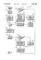
- FIG. 3is a flow diagram of the "executive -- control" function which forms a portion of the control process shown in FIG. 1;
- FIG. 4is a diagram of a set of mechanical input devices and an instrument panel for the simulated vehicle of the driver training system shown in FIG. 1;
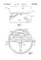
- FIG. 5is a side elevational view of one presently preferred embodiment of a seat and low frequency speaker assembly for the driver training system wherein the speaker is mounted in a floor mounted base, shown in cross-section, under the seat;
- FIG. 6is a top plan view of the base of the low frequency speaker assembly taken along line 6--6 of FIG. 5;
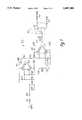
- FIG. 7is an electrical schematic showing one presently preferred embodiment of a relay control circuit which is connected to the low frequency speaker shown in FIG. 5;
- FIG. 8is a side elevational view of another presently preferred embodiment of a seat and low frequency speaker assembly for the driver training system of the present invention wherein the speaker is mounted in the back of the seat;
- FIG. 9is a cross-sectional side view of the mechanical structure of one presently preferred embodiment of an ABS brake simulation assembly of the present invention.
- FIG. 1shows one presently preferred embodiment of a driver training system 100 of the present invention.
- the driver training system 100is operated by a user 102 (shown schematically), who desires to improve driving performance. It should be understood that the driver training system 100 as hereinafter described is applicable to any type of vehicle that is operated by a human.
- the present inventionincludes simulations which are easily generalized to driver training systems for all kinds of simulated vehicles and all types of driving.
- driver training system 100comprises a vehicle simulator for police training.
- the user 102can be an instructor or a student.
- the user 102preferably sits in a booth or housing (not shown) such as the one described in the assignee's U.S. patent entitled “Rear Entry Booth and Adjustable Seat Apparatus for a Sit-Down Arcade Video Game,” U.S. Pat. No. 4,960,117. In that way, distractions are minimized and the user 102 can concentrate on self-improvement of his driving technique.
- the user 102moves a turn signal lever 104, manipulates a plurality of dash and column switches 105, manipulates a key turned ignition switch 107 for starting the simulated automobile, depresses a brake pedal 106 which is part of an ABS brake simulation system 500 and depresses a gas pedal 108 in the customary manner.
- an automatic transmission shifter 110is manipulated by the user 102 to select a reverse gear or one of a plurality of forward gears.
- a steering wheel 112is turned by the user 102 so as to guide the simulated vehicle in the desired direction of travel.
- the mechanical inputs provided by the user 102 to the input devices 104, 105, 108, 110 and 112are translated by transducers into electrical signals which are fed into a computer 114.
- the mechanical inputs on the brake pedal 106are translated into electrical signals by the ABS brake system 500 and the signals are fed to a bridge interface circuit 546 connected to the computer 114.
- the computer 114further receives both inputs and downloaded programs from a personal computer (PC) 103 which is preferably an IBM compatible computer having a 100 megabyte hard drive and a 4 megabyte RAM.
- the personal computer 103 and the computer 114are interactively connected via a communication link 140.
- the link 140should be capable of handling high speed digital data transmissions, on the order of 10 megabits per second, and it preferably includes a communication circuit such as an ADSP 2105 or 2101 manufactured by Analog Devices to ensure sufficiently rapid communication between the computer 114 and the personal computer 103.
- a communication circuitsuch as an ADSP 2105 or 2101 manufactured by Analog Devices to ensure sufficiently rapid communication between the computer 114 and the personal computer 103.
- the computer 114includes a general purpose microprocessor such as a Motorola 68000 (not shown) or another member of the Motorola 680x0 microprocessor family.
- a general purpose microprocessorsuch as a Motorola 68000 (not shown) or another member of the Motorola 680x0 microprocessor family.
- One function of the 68000 microprocessoris palette manipulation.
- the computer 114preferably includes a model processor (DSP), such as an AT&T DSP32C, a digital signal processor (ADSP), such as an Analog Devices ADSP-2101, and a graphics processor (GSP) such as a Texas Instruments 34010 Graphic System Processor, none of which are shown.
- DSPmodel processor
- ADSPdigital signal processor
- GSPgraphics processor
- the DSPperforms velocity, acceleration, and position calculations.
- the ADSPprovides the "higher-level" functions of video display such as translation, rotation, scaling, and shading while the GSP efficiently performs dither patterning, rendering, and the low-level graphics work of writing polygons (so-called polygon graphics) to the video display 122.
- the presently preferred computer 114also includes a read only memory (ROM) comprising 256 kilobytes of storage for self test; as well as a random access memory (RAM) comprising: 1.75 megabytes for downloaded programs, object definition data, and graphics universe data, an additional 0.5 megabytes of shared memory for additional downloaded graphics object data, shared with the 68000 processor.
- ROMread only memory
- RAMrandom access memory
- the center monitor in the video display 122(FIG. 1) also includes an additional 1 megabyte of RAM for downloaded scenario traffic data.
- the presently preferred computer 114also incorporates additional random access memories for each processor as follows: DSP--64 kilobytes; ADSP--12 kilobytes of program memory (for the programs downloaded from the personal computer 103), 16 kilobytes of buffer memory; and GSP--45 kilobytes of program memory (for the programs downloaded from the RAM or the personal computer 103) and 640 kilobytes of display memory.
- the GSPfurther employs video random access memory (VRAM) for improved video display rates.
- VRAMvideo random access memory
- the computer 114executes computer software which is stored in a memory (not shown) such as a 128 ⁇ 8K, 70-100 nsec Random Access Memory (RAM).
- the software executed by the computer 114 that is stored in this RAMcan be one of a number of software scenarios of programs relating to driving stored within the PC 103 which can be downloaded into the RAM in response to commands executed at the PC 103.
- the computer software executed by the computer 114is logically organized to include a control process 120.
- the control process 120receives digitized signals from the input devices 104-112 as well as other digitized input signals from the personal computer 103. The control process 120 then passes data from these digitized signals, across a data path 118, to a model process 116 that models the velocity and acceleration vectors of the simulated car. Thus, at a time T, position data, i.e., the Cartesian coordinates of the car, are determined by the model process 116. The position data is made available, across the data path 118, back to the control process 120.
- the control process 120applies the "rules of the road" to the new position of the car, and initiates signals to drive a video display 122, a pair of speakers 123 and 124, a low pass filter 454 and an instrument panel 130.
- the filter 454provides a low pass filtered signal to an amplifier 450 which is connected to a relay 452, which in turn is connected to a speaker 430 positioned adjacent to a user's seat 402 (FIGS. 5 and 8).
- the relay 452is preferably a low voltage relay manufactured by Potter & Brumfield, model no. T70L5D, and is further coupled to a relay control circuit 456 which disconnects the speaker 430 when the system 100 is either powering up or down.
- the control process 120further provides a user viewpoint into a graphical representation of the vehicle universe.
- the computer 114generates polygon graphics to the video display 122.
- One preferred video display devicesuch as model no. 25K7191 available from Wells-Gardner of Chicago, Ill., is a multi-synchronous display that can be configured to display 512 ⁇ 288 pixels.
- the video display 122may include a plurality of video devices arranged in a semi-circle to give the user 102 a simulated view similar to that of a real car. This arrangement is described in the assignee's copending U.S. patent application entitled "Modular Display Simulator," Ser. No. 07/704,373.
- the video display 122preferably generates a color, three-dimensional graphical representation of the environment, i.e., the user's perspective of a graphical universe including items such as a roadway.
- the speakers 123 and 124produce sounds such as gear changes, engine revving, skidding, and so on.
- the low frequency speaker 430is preferably mounted adjacent to the seat 402 (FIG. 5) to simulate feel of the road.
- the instrument panel 130includes a speedometer to indicate the speed of the simulated vehicle, an indicator for the gear selected by using the shifter 110, left and right arrow lights to indicate a direction selected by using the turn signal lever 104, and various other indicator lights.
- the user 102is presented with real-time feedback from the output devices 122, 123, 124, 130 and 430 that is personalized according to his own individual performance and what he encounters in the simulated universe.
- the control process 120further provides feedback to simulate the feeling of a steering wheel in a real automobile while being driven. This is preferably accomplished in the same manner as described in assignee's patent "Control Device such as a Steering Wheel for Video Vehicle Simulator With Realistic Feedback Forces", U.S. Pat. No. 5,044,956.
- the control process 120in response to inputs from the ABS brake system 500 via a bridge interface circuit 546, also provides feedback to the brake pedal 106 with the ABS brake system 500 thereby simulating the feeling of brakes on an automobile equipped with an ABS braking system on the brake pedal 106.
- a simulation programis downloaded from the personal computer 103 to the computer 114 which will execute the program.
- the computer 114then generates a graphics universe to be displayed to the user 102 via the video display 122 along with associated sounds via the speakers 123, 124.
- the user 102in response to what he sees in the video display 122 and what he hears from the speakers 123, 124 manipulates the driving controls to thereby drive the simulated vehicle.
- the user 102starts the automobile via the ignition switch 107, puts the automobile in gear via the automatic transmission shifter 110, depresses the gas pedal 108 to make the automobile move, depresses the brake pedal 106 to make the car stop and steers the automobile with the steering wheel 112.
- the control process 120 of the computer 114passes data to the model process 116 via the data path 118 which enable the model process 116 to model the velocity and acceleration vectors of the simulated vehicle thereby determining the Cartesian coordinates of the vehicle. This data is then passed back to the control process 120 via the data path 118 and is then used by the control process 120 to provide additional signals to the user 102.
- the Cartesian coordinates as determined by the model process 116may determine that the user 102 has driven the simulated vehicle over a cone in the simulated universe, hence the control process 120 causes the speaker 123, 124 to generate an appropriate noise, cause the feeling of hitting a cone to be generated and felt by the user 102, via the low frequency speaker 430, as well as cause the steering wheel 112 to vibrate in the hands of the user 102 in response to hitting the cone. Further, the control process 120 will also provide feedback to the user 102 through the ABS brake system 500 when the user 102 applies the brakes sufficiently hard to enable the system.
- FIG. 2is a diagram of a video screen display showing one example of a course upon which the user 102 (FIG. 1) may operate the vehicle. From the first person viewpoint of FIG. 2, it is seen that the user 102 is "placed inside" of the vehicle being simulated. The user 102 views a three-dimensional simulated graphical universe 139 as projected onto the two dimensional screen of the video display 122. The scene represented in FIG. 2 is one wherein the user 102 is looking forward out of a windshield while driving the simulated vehicle and proceeding on the track.
- the user 102is presented with a course 142, which is a specific instance of the universe 139.
- the user 102has the basic objective of trying to drive through the course at a desired speed without hitting any obstacles, i.e., a configuration of cones 143.
- the computer 114will also cause an appropriate background to be displayed. In the illustrated case, this is a cityscape 144 framed against a blue sky 146.
- This and other tracks, having different configurations or objectives, e.g., teaching the user 102 how to pursue other cars in traffic,can be selected by the user 102 or downloaded, preferably by an instructor, from the personal computer 103. Since the presently preferred system 100 of the present invention does not use a timer or score points, the user 102 will not feel a need to drive as fast as possible, but instead, will concentrate on learning proper technique.
- FIG. 3illustrates the flow diagram for the top-level function of the control process 120 (FIG. 1) called "executive -- control".
- the control process 120is written in the "C” language and cross-compiled using a Green Hills Software, Inc. "C” compiler available from Oasys, a division of Xel, Inc. of Waltham, Mass. The control process 120 is then executed on a Motorola 68000 microprocessor located in the computer 114.
- a Motorola 68000 microprocessorlocated in the computer 114.
- Computer source code of relevant portions of the control process 120is attached herewith in the accompanying Microfiche Appendix.
- a programPrior to a start state 220, a program is downloaded from the computer 103 to the computer 114.
- the user 102(FIG. 1) then presses an abort/select rocker switch (not shown) which is one of the column and dash switches 105.
- the computer 114(FIG. 1) directs the video display 122 to display a series of menus from which the user may, depending on the program that is being run by the computer 114, select the type of car, or the type of weather. The selection is accomplished by manipulating one or more of the rocker switches (not shown) which are part of the dash and column switches 105.
- a series of default choiceswill be made for the type of vehicle and weather. After selections are made for vehicle and weather, if desired, or the default choices are accepted, the user 102 selects the "start scenario" option and then manipulates a rocker switch (not shown) to signal the computer 114 to move to the next state.
- the computer 114(FIG. 1) then moves from the state 222 to a state 224 where the computer 114 will initiate a process by which the path followed by the observer vehicle in the upcoming scenario will be recorded. This recording can be played back at a later time to permit analysis and critique of the performance of the use during the scenario.
- the computer 114moves from the state 224 to a state 226 wherein the computer 114 will perform a loop until the abort/select switch is pressed up (abort) or the user 102 has crashed.
- the loopencompassing a series of states 226 through 248, is preferably completed by the computer 114 sufficiently quickly so that position information can be displayed in real-time providing the observer car and environment with fluid movement effects on the video screen 122, the speakers 123, 124, and the low frequency speaker 430.
- the position of the observer caris obtained from the model process 116 (FIG. 1).
- the model process 116calculates the last position of the observer car based upon the user's inputs which occur asynchronously.
- the computer 114generates output signals including sounds via the speakers 123 and 124, road feel cues via the speaker 430, vibrations on the steering wheel 112 and pulsations on the brake pedal 106 via the ABS system 500.
- a cone courseis a course where the user 102 will drive an automobile on a track containing cones. If a cone course has been selected or assigned, the computer 114 moves on to a "cones" function 234 wherein the user 102 is given choices on performance feedback. If a cone course was not chosen as determined by state 232, the computer 114 proceeds to state 236. At state 236, if the user 102 has selected or been assigned one of the pursuit tracks wherein the user 102 is required to pursue a specific automobile, the pursuit car, through the simulated universe, the recorded position of the pursuit car is updated.
- a display commandis initiated to the digital signal processor (not shown) in the computer 114 (FIG. 1), such as the ADSP-2101 chip available from Analog Devices of Norwood, Mass.
- the digital signal processornot shown
- display objectssuch as the track, background (houses, etc.), the pursuit car (if on a pursuit track) and the observer car, are appropriately translated in the graphical universe 139 (FIG. 2) according to the perspective of the user 102, for later display on the video display 122.
- the instrument panel 130including the speedometer, turn signal indicators, and various indicator lights, is updated.
- a separate fuel gauge(not shown) is also updated.
- collision sounds, sounds associated with the observer car colliding with barriers, cones, buildings and the likeare generated if the computer 114 determines that the simulated vehicle has collided with something.
- the video display 122has its three-dimensional graphics display updated by a command being issued to the graphics signal processor such as, for example, the 34010 chip distributed by Texas Instruments, which can handle color filled three-dimensional graphics in real-time.
- the computer 114moves to state 226 to begin the next pass of the loop.
- the instrument panel 130 of the system 100includes a speedometer 302, a transmission gear indicator display area 304, a transmission gear indicator 306, a indicator and warning light area 308.
- Several input devices of the system 100including the turn signal lever 104, the automatic transmission or shift lever 110, and the steering wheel 112, are also shown.
- the speedometer 302 and indicatorsbecome active when the user 102 (FIG. 1) "starts" the simulated vehicle.
- the speedometer 302provides a measurement of velocity.
- the gear indicator 306visually displays the position of the shift lever 110 upon the gear indicator display area 304.
- the indicator and warning light area 308includes the following designators (left to right): left turn signal 308a, temperature, battery, seat belt, brake, oil pressure, high beam (headlights), emergency flasher, and right turn signal 308b.
- the turn signal lever 104is mounted on a steering column housing 310.
- FIG. 5is a side elevational diagram of one preferred embodiment of a seat and low frequency speaker assembly 400 shown in partial cross-section.
- the purpose of the assembly 400is to provide the user 102 (FIG. 1) with meaningful and realistic road feel cues.
- the assembly 400includes a seat 402, preferably made of a light weight plastic or upholstered wood, upon which the user 102 will sit while operating the system.
- the seat 402is movably mounted on a housing 404, preferably made of thick metal, containing a seat adjust mechanism (not shown).
- the seat adjust mechanismcan be of any type known in the art which permits the user 102 to adjust the seat 402 into a preferred position relative to the driving controls (not shown). Seat adjustment is accomplished by the user 102 manipulating a seat adjust control 406.
- the seat adjust mechanism housing 404is attached to the top of a mounting post, generally indicated by the reference numeral 408.
- the mounting post 408is cylindrical and preferably made of a solid material such as stainless steel, with a top portion 409 and a bottom portion 410, the bottom portion 410 having a smaller diameter than the top portion 409.
- a cylindrical bearing 412is mounted flush on the bottom portion 410 of the mounting post 408.
- the bottom portion 410 of the mounting post 408extends through a mounting hole 414 (FIG. 6) in a swivel base 416.
- the mounting hole 414is preferably 4 inches in diameter which is slightly larger than the outer diameter of the bottom portion 410 of the mounting post 408.
- the bearing 412is mounted on the bottom portion 410 of the mounting post 408 such that when the bottom portion 410 extends through the mounting hole 414 the upper surface of the bearing 412 will be positioned between the upper portion 409 and the upper surface of the swivel base 416.
- the bearing 412can be of any type known in the art which will facilitate swiveling the seat 402.
- the swivel base 416is preferably made of stainless steel and is flushly mounted on top of a seat mounting plate 420 and is primarily secured thereto by four screws 422 (two shown) which extend through the seat mounting plate 420 into a semi-rigid diaphragm 424.
- a securing member 426is attached to the bottom portion 410 of the mounting post 408 underneath the swivel plate 416, such that the securing member 426 prevents the mounting post 408 from being lifted out of the mounting hole 414 while still permitting the seat 402 to swivel.
- the securing member 426can be comprised of a nut and lock washer used in combination with threads on the bottom portion 410 of the mounting post 408 or any other combination which secures the mounting post 408 in the described fashion while still permitting the seat 402 to be swiveled.
- the swivel plate 416is attached to the seat mounting plate 420, which is preferably a 16 inch by 18.75 inch piece of 3/4 inch thick plywood with beveled edges.
- the seat mounting plate 420is further attached to the semi-rigid diaphragm 424.
- the semi-rigid diaphragm 424is preferably a 29.80 inch by 35.50 inch piece of 1/2 inch or 3/8 inch thick plywood, the top of which is covered by corrugated rubber matting 425 (FIG. 6) suitable for providing secure footing for the user 102.
- the semi-rigid diaphragm 424must be sufficiently flexible so that it can vibrate in response to changes in air pressure induced by the low frequency audio speaker 430 positioned on an adjacent enclosure 428. The operation of the speaker 430 and the enclosure 428 will be discussed in greater detail below.
- the vertical support members 432are preferably made from 3/4 inch thick particle board, and they are connected to the semi-rigid diaphragm 424 along its outside perimeter so that they extend perpendicularly downward.
- a horizontal support member 434is Connected to the bottom surfaces of the vertical support members 432, preferably made from 3/4 inch thick particle board, which serves as a base plate for the assembly 400.
- the length and width dimensions of the horizontal support member 434are substantially identical to the dimensions of the semi-rigid diaphragm 424 such that when the semi-rigid diaphragm 424, the vertical support members 432 and the horizontal support member 434 are assembled, they form a rectangular box-like structure.
- the four cleats 436preferably consist of lengths of mahogany wood with a 3/4 inch square cross section. Where the cleats 436 intersect near the corners of the semi-rigid diagram 424, they are preferably joined to each other in a substantially air-tight fashion.
- a speaker member 440Attached to the bottom side of the cleats 436, in a substantially air-tight fashion, is a speaker member 440.
- the speaker member 440is preferably a 27.80 inch by 33.50 inch rectangular piece of 3/4 inch thick particle board.
- the speaker member 440further contains a circular hole 442 with approximately a 7 inch diameter.
- the speaker 430is mounted to the underside of the speaker member 440, preferably in a substantially air-tight fashion, so that the diaphragm of the speaker 430 is substantially centered about the hole 442 and is exposed to the air within the enclosure 428.
- the enclosure 428is thereby formed by the semi-rigid diaphragm 424, the cleats 436, the speaker member 440, the speaker 430, and the swivel base 416.
- the enclosure 428is air-tight, however, perfect air-tight integrity is not a requirement for the operation of the assembly 400.
- the speaker 430is a model QUAM-NICHOLS, eight inch, 8 Ohm, 50 Watt two terminal woofer speaker part number 92-9846.
- FIG. 6is a top plan view of the base portion of the seat and speaker assembly, taken along line 6--6 of FIG. 5.
- FIG. 6selectively shows the relative mounting locations and sizes of some of the members which comprise the base containing the speaker 430 and the enclosure 428 of the presently preferred embodiment.
- two direction arrows 444 and 446are shown in FIG. 6.
- the mounting hole 414 in the plate 420is preferably offset from the center of the plate 420 by approximately 4 inches in direction of the arrow 446 and approximately 3 inches in the direction of arrow 444.
- the mounting post 408(shown in FIG. 5), extends perpendicularly outward from hole 414 and is preferably coupled to the seat adjust mechanism housing 404 (shown in FIG. 5) offset from the center of the housing 404 in the same direction as the arrow 444 by the same distance as the mounting hole 414 is offset in the direction of the arrow 444 from the center of the plate 420.
- the seat 402When the seat 402 is oriented in its nominal operational position, facing in the opposite direction as the arrow 446, as shown in FIG. 5, the seat 402 will be located such that it is centered over the seat mounting plate 420 in the direction of the arrow 444 while being offset approximately 4 inches from being centered over the plate 420 in the direction of the arrow 446. Positioning the seat 402 in this fashion permits easier access to the seat 402 by the user 102 as the seat 402 can be swiveled so when the seat 402 faces in the direction of the arrow 444, the edge of the seat 402 will preferably extend beyond the edge of the semi-rigid diaphragm 424.
- FIG. 6also shows the locations of four holes 423 for the four screws 422 which secure the swivel plate 416 (see FIG. 5) to the seat mounting plate 420 and to the semi-rigid diaphragm 424.
- the speaker hole 442is located substantially at the center of the speaker member 440 (FIG. 5). As shown in FIG. 6, the hole 442 is then located in the speaker member 440 underneath and at the approximate center of the semi-rigid diaphragm 424.
- the top surface of the semi-rigid diaphragm 424is preferably covered by the corrugated rubber matting 425, shown in part in FIG. 6.
- This matting 425is preferably fixedly attached to the semi-rigid diaphragm 424 through the use of tacks or glue. Also shown in FIG. 6 are the cleats 436, mounted underneath the semi-rigid diaphragm 424, which are also shown to meet and join each other at their ends.
- the control process 120receives input from the model process 116 indicating that an event, e.g., collision with an object, engine vibration and so forth is occurring.
- the control process 120access a digital representation of a signal in a wave table (not shown) stored in one of the RAMs of the computer 114.
- the wave tablestores a well-known digital representation of the frequency content, the amplitude and the duration of the signals corresponding to various events, e.g., collision with specific objects, engine noise.
- the control process 120reproduces the digital representation and causes its translation into an analog signal representative of the specific event which is then fed to the low pass filter 454.
- Computer source code of relevant portions of the control process 120 which accesses the digital signalis attached herewith in the accompanying Microfiche Appendix.
- the filter 454is a low pass filter with a frequency response of 20 to 80 Hertz (Hz), hence, only signals with a frequency content below 80 Hz will be passed by the filter 454 to the amplifier 450.
- the amplifier 450is a 28 Watt power amplifier capable of producing a 24-volt, peak-to-peak output signal at maximum gain. Hence, the amplifier 450 increases the amplitude of the low frequency signal it receives from the low pass filter 454 and feeds this amplified low frequency signal to the relay 452.
- the relay 452is designed to protect the speaker 430 from damage caused by voltage spikes generated by either powering up or powering down the system 100.
- voltage spikesgenerated by either powering up or powering down the system 100.
- transient voltage spikesare generated which, if transmitted to audio-speakers of a type similar to speaker 430, can result in damage to the speakers. Even if these transients do not damage the speaker 430 they may unsettle the user 102 sitting in the seat 402. Consequently, the relay 452 is connected to the control circuit 456, described below, which will disconnect the speaker 430 from the electrical circuitry of the system 100 during periods of power transition.
- the relay 452will send the high amplitude, low frequency signal received from the amplifier 450 to the speaker 430.
- the diaphragm of the speaker 430will then vibrate in response to the high amplitude, low frequency signal, thereby displacing the air within the enclosure 428.
- This displacement of the air within the enclosure 428causes the semi-rigid diaphragm 424, which shares common structural components with the enclosure 428, to bounce or vibrate.
- the vibration of the semi-rigid diaphragm 424is then communicated through the seat mounting plate 420 and the seat mounting post 408 to the seat 402 and then to the user 102. In this fashion, events such as engine vibration, hitting an object, and so forth can be realistically represented to the user 102 of the simulation system 100.
- the control process 120retrieves a wave sample of the sound from the wave table (not shown) and feeds the equivalent analog signal, having a sharp low frequency-peak to the filter 454.
- the filter 454passes the low frequency content (below 80 Hz) of the signal to the amplifier 450
- the amplifier 450increases the amplitude of the signal and passes it to the relay 452. This high amplitude signal will then be sent to the speaker 430 if the system 100 is not in a period of power transition.
- the speaker 430communicates a high excursion pulse through to the air within the enclosure 428 by vibrating the diaphragm of the speaker 430.
- the resulting displacement and consequent compression of air within the enclosure 428is transmitted to the semi-rigid diaphragm 424 and ultimately to the user 102 sitting on the seat 402.
- the user 102will then experience a quick jolt to simulate the feel of hitting the cone as the speaker diaphragm moves the air in the enclosure 428.
- the control process 120can cause different samples of sound stored in the wave table to be transmitted, in the above-described fashion, to the user 102 for a single event.
- the low frequency signal generated by the control process 120 for a cone collisionmay have a duration in the range of 100 milliseconds to one second. Other signals, such as those defining engine vibration may have longer duration.
- the control processprovides independent signals to the speakers 123 and 124 which are indicative of engine noises, cone collisions and so forth. Included in the Microfiche Appendix is the source code used by the control process 120 to implement the operation of the wave table herein described.
- the relay control circuit 456is more fully described by reference to FIG. 7.
- the relay control circuit 456is designed to turn the relay 452 off during periods of power transition, e.g., when powering up and when powering down the system 100.
- the circuit 456is designed so that when the actual voltage for the system 100 falls below its normal input voltage, preferably 12 VAC, the relay 452 will disconnect the input to the speaker 430 from the output of the amplifier 450.
- the operation of the circuit 456, shown in FIG. 7will now be described.
- a capacitor 460coupled to the non-inverting input (+) of a comparator 464.
- a capacitor 463which is connected to the inverting (-) input of the comparator 464 is charged by a reference voltage (Vref), preferably 14 volts, through a resistor 462.
- a capacitor 470which is connected to the non-inverting (+) input of a comparator 473, is also charged by the reference voltage (Vref) through a resistor 469.
- the comparator 464When the voltage on the non-inverting (+) input of the comparator 464 exceeds the voltage on the inverting input of the comparator 464, the comparator 464 outputs a high voltage which causes slow charging of capacitor 472 and that appears on the inverting (-) input of comparator 473. When the voltage on the inverting (-) input of the comparator 473 exceeds the voltage on the non-inverting (+) input of comparator 473, the output of the comparator 473 goes low will then energize the coil of the relay 452 thereby connecting the speaker 430 to the amplifier 450.
- the circuit 456When the power to the system 100 is turned off, the circuit 456 operates as follows.
- the capacitor 460rapidly discharges dropping the voltage on the non-inverting (+) input of the comparator 464 beneath the voltage on the inverting (-) input of comparator 464 and thereby turning this comparator off. Consequently, a voltage on the inverting (-) input of the comparator 473 will decrease. This results in the comparator 473 turning off as the voltage on the non-inverting (+) input of comparator 473 is greater than the voltage on the inverting (-) input. With the comparator 473 turned off (goes high), the coil of the relay 452 is de-energized, which results in the relay 452 disconnecting the speaker 430 from the amplifier 450.
- the circuit 456will delay energizing the coil of the relay 452 to connect the speaker 430 to the amplifier 450 for a relatively long time, preferably approximately 4 seconds, thereby permitting any transients which would cause damage to the speaker 430 to dissipate.
- itwill be desirable to quickly disconnect the coil of the relay 452 from the amplifier 450, preferably within approximately 16 milliseconds, to prevent any transients being transmitted to the speaker 430.
- Values of one presently preferred embodiment of the component parts of circuit 456are shown in Table 1 below. When used in the circuit configuration shown in FIG. 7, a suitably long delay turn-on time with a suitably quick turn-off time is achieved.
- FIG. 8is a side elevational diagram showing a cross section of another preferred embodiment of a seat and low frequency speaker assembly 480.
- the purpose of the assembly 480is also to provide the user 102 (FIG. 1) with meaningful and realistic road feel cues.
- the assembly 480includes a seat 482 that has at least a portion of its interior hollow with a recess 484.
- the recess 484has the low frequency speaker 481 which is connected to the simulation system 100 in the same manner as is the speaker 430 (FIG. 1) mounted and secured such that a diaphragm of the speaker 481 is in communication with the air that is enclosed in the envelope or bladder 486 of the seat.
- the diaphragm of speaker 481moves back and forth in a conventional manner in response to a signal presented at the speaker terminals. This back and forth motion is communicated through the air creating vibration on the surfaces 488 of the seat 482.
- the surfaces 488are made of a somewhat flexible but strong plastic material.
- the back and bottom surfacesare somewhat thicker and hence stiffer, while the surfaces in contact with the user 102 (FIG. 1) are thinner to flex in response to the vibration of the air.
- the surfaces in contact with the user 102may be overlaid with a cover and cushion 489.
- the speaker 481 of this presently preferred embodimentis a model 40-1348 dual-coil eight inch speaker sold by Radio Shack.
- the speaker 481has four terminals, a first set of terminals 490 is visible in FIG. 8.
- the speaker 481is fastened to the seat 482 by four bolts, the locations of two are indicated by a pair of holes 483a and 483b.
- the speaker 481is connected to the control process 120 (FIG. 1) of the system 100 through the relay 452, the amplifier 450, and the low pass filter 454 in the same fashion as was the speaker 430 in the preferred embodiment shown in FIGS. 5 and 6 and it receives signals indicative of road feel cues in the same fashion as described above.
- FIG. 9shows a cross-sectional view of the ABS brake pedal system 500 with the attached brake pedal 106 of the preferred embodiment of the present invention shown in FIG. 1.
- the ABS brake pedal system 500is mechanically arranged so that the brake pedal 106 provides for movement which simulates the movement of a brake pedal in a real automobile.
- the ABS brake pedal system 500includes a mounting plate 502 having a back side 503 and a front side 505.
- the mounting plateincludes a plurality of mounting holes 504 (two shown) through which screws (not shown) are used to secure the ABS brake pedal system 500 to the housing (not shown) of the simulator system 100 in a similar orientation as brake pedals in a typical automobile.
- a connector rod 506extends through a hole in the mounting plate 502.
- the portion of the connector rod 506 extending out from the back side 503 of the mounting plate 502is preferably threaded. Coupled to the threaded portion of the connector rod 506 is a washer 508 which is positioned on the connector rod 506 so as to be sitting adjacent to the back side 503 of the mounting plate 502.
- a cylindrical elastic bumper 510 having an opening slightly larger than the diameter of the connector rod 506, and a spring 512are both positioned on the threaded portion of the connector rod 506 adjacent to the washer 508.
- the inner diameter of the spring 512is slightly larger than the outer diameter of the bumper 510 so that when the bumper 510 is positioned on the connector rod 506, the spring 512 is then mounted over the bumper 510.
- a washer 514capable of retaining and compressing the spring 512, is also positioned on the connector rod 506 so that the spring 512 and the elastic bumper 510 are positioned in axial alignment with the connector rod 506 between the washer 514 and the washer 508.
- the spring 512is longer than the elastic bumper 510 so that the spring 512 will have to be compressed before the elastic bumper 510 can make contact with both of the washers 508 and 514 at the same time.
- a nut 516adjustably secures the washer 514 to a specified position on the connector rod 506.
- the portion of the connector rod 506 which projects out from the front 505 of the mounting plate 502is connected to a cross piece 518 which, in turn, connects two identical force multiplier arms 519 (one shown).
- An elastic rebound bumper 520is positioned on the portion of the connecting rod 506 between the mounting plate 502 and the cross piece 518.
- the top end of each of the force multiplier arms 519is respectively bolted to one of two arms 521 of an electrically controlled solenoid 522 in such a manner that when current is supplied to the solenoid 522, the force multiplier arms 519 move in response thereto.
- An adjustment screw 528is also mounted on another cross-piece (not shown) connected between the force multiplier arms 519.
- the adjustment screw 528extends through the cross piece connecting the force multiplier arms 519 to a lever arm 526.
- the adjustment screw 528permits the user 102 to adjust the amount of motion of the force multiplier arms 519, relative to the lever arm 526, induced by the solenoid 522. Hence, tightening the adjustment screw 528 decreases the amount by which the force multiplier arms can travel relative to the lever arm 526.
- the bottom ends of both of the force multiplier arms 519are connected via a bolt 532 and a nut (not shown) to a brake pedal member 530.
- the solenoid 522is secured to the top of a plate 524, the bottom surface of the plate 524 is, in turn, secured to a lever arm 526 which projects perpendicularly downward from the plate 524.
- the lever arm 526is welded near its bottom end to the brake pedal member 530 along the length of the lever arm 526 intersecting the surface of the brake pedal member 530.
- a strain gauge 534is preferably bonded to the material of the lever arm 526 in a position to sense strain in the lever arm 526 as force is applied to the brake pedal 106.
- the strain gauge 534is of conventional structure and may be either of the metallic or semiconductor type.
- the strain gauge 534is essentially a serpentine resistive path that will either elongate or shorten as strain is applied to the lever arm 526 thereby resulting in a change of resistance, which can be detected by an appropriate electrical circuit to be discussed below.
- the brake pedal member 530is a substantially L-shaped member which initially extends substantially downward from the force multiplier arms 519 and then extends substantially outward from the mounting plate 502 to where the brake pedal member 530 terminates in the brake pedal 106.
- the brake pedal 106preferably is identical to typical brake pedals in real automobiles.
- the brake pedal member 530is also fixedly connected to a pivot bearing member 538.
- the pivot bearing member 538preferably comprises a metal cylinder which is horizontally mounted between two rectangular securing members 540 (one shown) which are mounted on the front side 505 of the mounting plate 502.
- the mechanical operation of the ABS brake pedal systemwill now be described in conjunction with FIGS. 1 and 9.
- the user 102places his foot upon the brake pedal 106 and depresses it in the same fashion as a driver would depress a brake pedal in an actual car.
- the brake pedal member 530pivots about the pivot bearing member 538 in the direction of an arrow 542. This causes the segment of the brake pedal member 530 above the pivot bearing 538 to be urged to move in the direction depicted by an arrow 544.
- the connector rod 506includes an attached washer 514 and nut 516
- movement of the connector rod 506 in the direction of the arrow 544also results in movement of the washer 514 and nut 516 in the positive X-direction.
- the washer 514As the washer 514 is moved in the positive X-direction it compresses the spring 512, which in turn causes linearly increasing force to be exerted against the washer 514 in the negative X-direction.
- the spring 512will be compressed to the point where the washer 514 will make contact with the elastic bumper 510. At that point, greater force will be exerted against the washer 514 in the negative X-direction.
- the spring 510When the user 102 stops depressing the brake pedal 106 in the direction of arrow 542, the spring 510 will push the washer 514 and the connector rod 506 in the negative X-direction to their initial position, which will in turn cause the force multiplier arms 519, the brake pedal member 530 and the brake pedal 106 to return to their initial undepressed position.
- the amount of force exerted by the spring 512 and the elastic bumper 510 in opposition to the user 102 depressing the brake pedal 106 in the direction of the arrow 542can be adjusted by positioning the washer 514 at a different location along the connector rod 506 and securing it thereto with the nut 516.
- depression of the brake pedal 106 in the direction of arrow 542 in this manneralso results in straining the lever arm 526 causing the serpentine resistive path of the strain gauge 534 to either shorten or lengthen thereby changing its measured resistance.
- the strain gauge 534is electrically connected to the control process 120 of the computer 114 as shown in FIG. 1.
- additional electronic circuitryis required to translate the change in resistive value of the strain gauge 534 due to increased strain upon the lever arm 536 into an electronic signal that the computer 114 can utilize. Consequently, this embodiment of the invention includes a bridge/interface circuit 546 (see FIG. 1) of a type available in the marketplace.
- the bridge/interface circuit 546includes bridge circuitry which may be used to detect the slight changes in the resistance of the strain gauge 534. Further, the bridge/interface circuit 546 also includes interface circuitry which will convert the analog bridge circuit output signal to a digital format suitable for use by the control process 120.
- the bridge/interface circuit 546also includes interface circuitry which will convert the analog bridge circuit output signal to a digital format suitable for use by the control process 120.
- one of the difficulties of using strain gauges, and particularly sensitive silicon based strain gaugesis that these gauges have temperature drift characteristics which result in inaccurate readings. It is desirable in the quiescent state when no strain is being experienced by the lever arm 526 that the bridge be balanced to minimize these effects.
- the presently preferred bridge/interface circuitis substantially the same as the circuit shown in FIG. 9 of U.S. Pat. No. 4,949,119 to Moncrief, et al.
- the desirability of using such a circuitwas described in this patent at Column 7, lines 3-60 and the manner in which this circuit operated, both as a balancing bridge and as a analog to digital converter is described in detail at Column 9, line 16 to Column 10, line 32.
- U.S. Pat. No. 4,949,119 to Moncrief, et al.is hereby incorporated by reference.
- the ABS brake pedal system 500simulates the feeling the user 102 will feel through his foot when he is depressing the brake pedal 106 with sufficient force such that an ABS braking system would typically be activated in a real world automobile.
- a strainwill be induced upon the lever arm 526 which will then be detected by the strain gauge 534.
- the strain gauge 534is coupled to the bridge/interface circuit 546 which detects and translates the signal detected by the strain gauge into a signal which can be processed by the computer 114, and specifically the control process 120.
- the control process 120sends a pulsating voltage signal to the solenoid 522.
- the solenoid 522will cause the solenoid arms 521 to move back and forth in the positive and negative X-direction. This movement of the solenoid arms 521 causes the force multiplier arms 519 to vibrate. Since the force multiplier arms 519 are connected to the brake pedal member 530 which is in turn connected to the brake pedal 106, vibration of the force multiplier arms 519 will ultimately be felt by the user 102 as he depresses the brake pedal 106.
- the amplitude of this induced vibration of the force multiplier arms 519can be controlled by tightening or loosening the adjustment screw 528 attached thereto. Consequently, by adjusting the screw 528, the vibration felt by the user 102 while depressing the brake pedal 106 can be made to approximate the feeling of an actual brake pedal in an actual ABS equipped car when the ABS brakes are being applied.
- control process 120will continue to send the pulsating voltage to the solenoid 522 so long as the simulated vehicle is still moving and the user 102 is still depressing the brake pedal 106 with sufficient force to initiate the pulsating voltage.
- the pulsating voltagepreferably has a 40 msec pulse width with a cycle period of 100 msec.
- the simulation systemthat Applicant has disclosed is capable of generating and transmitting a wide variety of road feel cues to the user of the simulator. These road feel cues can be stored and recalled when an event occurs within the simulated universe which would normally trigger a specific road feel in a real world automobile, e.g. hitting a bump etc. and are transmitted to the user by a mechanism which can accommodate and transmit a large number of feelings.
- the simulation system that Applicant has disclosedalso realistically represents the feel that the vehicle controls would have when operating in the real world.
- the driving embodiment of the present inventionincludes a steering wheel with feedback as well as a brake pedal which simulates the feeling of ABS brakes.
- a simulation system with these featuresprovides a more realistic representation of the real world, and a such, provides a better educational experience of how to operate this vehicle in the real world.
Landscapes
- Engineering & Computer Science (AREA)
- Theoretical Computer Science (AREA)
- General Physics & Mathematics (AREA)
- Multimedia (AREA)
- Physics & Mathematics (AREA)
- Aviation & Aerospace Engineering (AREA)
- Business, Economics & Management (AREA)
- Educational Administration (AREA)
- Educational Technology (AREA)
- Computer Graphics (AREA)
- Human Computer Interaction (AREA)
- Processing Or Creating Images (AREA)
- Fittings On The Vehicle Exterior For Carrying Loads, And Devices For Holding Or Mounting Articles (AREA)
Abstract
Description
TABLE 1 ______________________________________ PART IDENTIFIER PART NUMBER VALUE ______________________________________ 464 Comparator LM311 -- 473 Comparator LM311 -- 457 Diode IN4001 -- 474 Diode IN4001 -- 458 Resistor -- 10kΩ 459 Resistor -- 4.7 kΩ 461 Resistor -- 470Ω 462 Resistor -- 10kΩ 466 Resistor -- 82kΩ 467 Resistor -- 270Ω 469 Resistor -- 4.7 kΩ 471 Resistor -- 2.2μF 460 Capacitor -- 2.2 μF/50VμF 463 Capacitor -- 0.1μF 470 Capacitor -- 0.1μF 472 Capacitor -- 0.1μF 465 Capacitor -- 47μF 468 Capacitor -- 0.1 μF ______________________________________
Claims (22)
Priority Applications (1)
| Application Number | Priority Date | Filing Date | Title |
|---|---|---|---|
| US08/334,534US5607308A (en) | 1992-05-22 | 1994-11-04 | Vehicle simulator with realistic operating feedback |
Applications Claiming Priority (3)
| Application Number | Priority Date | Filing Date | Title |
|---|---|---|---|
| US07/888,375US5366376A (en) | 1992-05-22 | 1992-05-22 | Driver training system and method with performance data feedback |
| US08/018,950US5368484A (en) | 1992-05-22 | 1993-02-17 | Vehicle simulator with realistic operating feedback |
| US08/334,534US5607308A (en) | 1992-05-22 | 1994-11-04 | Vehicle simulator with realistic operating feedback |
Related Parent Applications (2)
| Application Number | Title | Priority Date | Filing Date |
|---|---|---|---|
| US08/018,950DivisionUS5368484A (en) | 1992-05-22 | 1993-02-17 | Vehicle simulator with realistic operating feedback |
| US08/299,040DivisionUS5619066A (en) | 1990-05-15 | 1994-08-31 | Memory for an electronic token |
Related Child Applications (1)
| Application Number | Title | Priority Date | Filing Date |
|---|---|---|---|
| US09/084,516ContinuationUS6217213B1 (en) | 1990-05-15 | 1998-05-26 | Temperature sensing systems and methods |
Publications (1)
| Publication Number | Publication Date |
|---|---|
| US5607308Atrue US5607308A (en) | 1997-03-04 |
Family
ID=26691675
Family Applications (3)
| Application Number | Title | Priority Date | Filing Date |
|---|---|---|---|
| US08/018,950Expired - LifetimeUS5368484A (en) | 1992-05-22 | 1993-02-17 | Vehicle simulator with realistic operating feedback |
| US08/334,874Expired - LifetimeUS5618178A (en) | 1992-05-22 | 1994-11-04 | Vehicle simulator with low frequency sound feedback |
| US08/334,534Expired - LifetimeUS5607308A (en) | 1992-05-22 | 1994-11-04 | Vehicle simulator with realistic operating feedback |
Family Applications Before (2)
| Application Number | Title | Priority Date | Filing Date |
|---|---|---|---|
| US08/018,950Expired - LifetimeUS5368484A (en) | 1992-05-22 | 1993-02-17 | Vehicle simulator with realistic operating feedback |
| US08/334,874Expired - LifetimeUS5618178A (en) | 1992-05-22 | 1994-11-04 | Vehicle simulator with low frequency sound feedback |
Country Status (4)
| Country | Link |
|---|---|
| US (3) | US5368484A (en) |
| EP (1) | EP0641471A1 (en) |
| JP (1) | JPH07507402A (en) |
| WO (1) | WO1993024915A1 (en) |
Cited By (38)
| Publication number | Priority date | Publication date | Assignee | Title |
|---|---|---|---|---|
| US5716281A (en)* | 1995-11-27 | 1998-02-10 | Sega Enterprises, Ltd. | Game apparatus using a vehicle with an optical image synthesizing system |
| US5802353A (en)* | 1996-06-12 | 1998-09-01 | General Electric Company | Haptic computer modeling system |
| US5868573A (en)* | 1994-08-15 | 1999-02-09 | Kerby; Robert Anthony | Vehicle control simulator |
| WO2000041155A1 (en)* | 1999-01-08 | 2000-07-13 | Meritor Light Vehicle Systems (Uk) Limited | Apparatus for the simulation and measurement of one or more operation characteristics of a device |
| US6162124A (en)* | 1996-11-05 | 2000-12-19 | Konami Co., Ltd. | Control lever device |
| US6409596B1 (en)* | 1997-09-12 | 2002-06-25 | Kabushiki Kaisha Sega Enterprises | Game device and image displaying method which displays a game proceeding in virtual space, and computer-readable recording medium |
| US20030073473A1 (en)* | 2001-09-19 | 2003-04-17 | Kazuhiro Mori | Computer program product |
| US20040147317A1 (en)* | 2003-01-10 | 2004-07-29 | Yutaka Ito | Game apparatus, game method and program |
| US20040158476A1 (en)* | 2003-02-06 | 2004-08-12 | I-Sim, Llc | Systems and methods for motor vehicle learning management |
| GB2403281A (en)* | 2003-06-21 | 2004-12-29 | David A Nicholson | Giving feel to a driving simulator brake pedal with a compressible stop |
| US20050091018A1 (en)* | 2003-09-05 | 2005-04-28 | Road Safety International, Inc. | System for combining driving simulators and data acquisition systems and methods of use thereof |
| US20050233810A1 (en)* | 2004-04-19 | 2005-10-20 | Yin-Liang Lai | Share-memory networked motion simulation system |
| US20060078854A1 (en)* | 2004-02-03 | 2006-04-13 | Drag Tag Pty Ltd. | Vehicle steering sensing apparatus |
| US20060136826A1 (en)* | 2003-02-14 | 2006-06-22 | Yohei Makuta | Riding simulation device |
| US20070238085A1 (en)* | 2006-01-13 | 2007-10-11 | Colvin Richard T | Computer based system for training workers |
| US20090018808A1 (en)* | 2007-01-16 | 2009-01-15 | Simbionix Ltd. | Preoperative Surgical Simulation |
| US20090232327A1 (en)* | 2008-03-13 | 2009-09-17 | Hagen Gary E | Automotive sensory enhancement system |
| US20100121645A1 (en)* | 2008-11-10 | 2010-05-13 | Seitz Gordon | Operating device for a motor vehicle |
| US20100280813A1 (en)* | 2009-04-30 | 2010-11-04 | Gm Global Technology Operations, Inc. | Portable usb power mode simulator tool |
| US7850456B2 (en) | 2003-07-15 | 2010-12-14 | Simbionix Ltd. | Surgical simulation device, system and method |
| WO2011019767A1 (en)* | 2009-08-10 | 2011-02-17 | Hindsight Manufacturing, Llc | Pedal simulator |
| US20110109134A1 (en)* | 2009-11-09 | 2011-05-12 | Cameron Anthony Filipour | Server-based gaming chair |
| WO2012061477A1 (en) | 2010-11-02 | 2012-05-10 | Promega Corporation | Coelenterazine derivatives and methods of using same |
| WO2012061529A1 (en) | 2010-11-02 | 2012-05-10 | Promega Corporation | Novel coelenterazine substrates and methods of use |
| US20120323434A1 (en)* | 1999-12-29 | 2012-12-20 | Hamrick Marvin R | G.P.S. Management System |
| US8543338B2 (en) | 2007-01-16 | 2013-09-24 | Simbionix Ltd. | System and method for performing computerized simulations for image-guided procedures using a patient specific model |
| EP2990478A1 (en) | 2009-05-01 | 2016-03-02 | Promega Corporation | Synthetic oplophorus luciferases with enhanced light output |
| US9501955B2 (en) | 2001-05-20 | 2016-11-22 | Simbionix Ltd. | Endoscopic ultrasonography simulation |
| US10046241B1 (en)* | 2010-11-01 | 2018-08-14 | Ronald Charles Krosky | Output production |
| WO2019232384A1 (en) | 2018-06-01 | 2019-12-05 | Promega Corporation | Inhibitors of oplophorus luciferase-derived bioluminescent complexes |
| US10659856B1 (en)* | 2018-04-16 | 2020-05-19 | Christopher Alan Pierce | Auditory low frequency sound reproduction and vibration generating speaker enclosure platform system |
| WO2021108765A1 (en) | 2019-11-27 | 2021-06-03 | Promega Corporation | Multipartite luciferase peptides and polypeptides |
| WO2021119149A1 (en) | 2019-12-10 | 2021-06-17 | Promega Corporation | Compositions and methods for bioluminescent detection using multifunctional probes |
| WO2021237118A2 (en) | 2020-05-22 | 2021-11-25 | Promega Corporation | Enhancement of kinase target engagement |
| EP4219736A1 (en) | 2014-09-12 | 2023-08-02 | Promega Corporation | Internal protein tags |
| WO2023194623A1 (en) | 2022-04-07 | 2023-10-12 | Asetek Danmark A/S | Driving simulator brake system with controlled pedal feedback |
| WO2023215505A1 (en) | 2022-05-04 | 2023-11-09 | Promega Corporation | Modified dehalogenase with extended surface loop regions |
| WO2023215514A2 (en) | 2022-05-04 | 2023-11-09 | Promega Corporation | Bioluminescence-triggered photocatalytic labeling |
Families Citing this family (137)
| Publication number | Priority date | Publication date | Assignee | Title |
|---|---|---|---|---|
| US5889670A (en) | 1991-10-24 | 1999-03-30 | Immersion Corporation | Method and apparatus for tactilely responsive user interface |
| US5790108A (en) | 1992-10-23 | 1998-08-04 | University Of British Columbia | Controller |
| US7345672B2 (en) | 1992-12-02 | 2008-03-18 | Immersion Corporation | Force feedback system and actuator power management |
| US6801008B1 (en) | 1992-12-02 | 2004-10-05 | Immersion Corporation | Force feedback system and actuator power management |
| NZ259483A (en)* | 1993-01-13 | 1996-11-26 | Roads Corp | Hazard perception test system having sequence of images with subject's ability determined by particular image selected |
| WO1995002801A1 (en) | 1993-07-16 | 1995-01-26 | Immersion Human Interface | Three-dimensional mechanical mouse |
| US5734373A (en) | 1993-07-16 | 1998-03-31 | Immersion Human Interface Corporation | Method and apparatus for controlling force feedback interface systems utilizing a host computer |
| US5623642A (en)* | 1994-04-06 | 1997-04-22 | M ak Technologies, Inc. | Method for simulating newtonian interactions over a computer network |
| KR970703691A (en)* | 1994-05-31 | 1997-07-03 | 쯔지모또 겐조오 | Sound system, play device and control method, play device using light and sound device |
| KR100229375B1 (en) | 1994-06-28 | 1999-11-01 | 이리마지리 쇼우이치로 | Game device and method of replaying game |
| US5669818A (en)* | 1995-03-23 | 1997-09-23 | Thorner; Craig | Seat-based tactile sensation generator |
| US6422941B1 (en)* | 1994-09-21 | 2002-07-23 | Craig Thorner | Universal tactile feedback system for computer video games and simulations |
| US20030040361A1 (en) | 1994-09-21 | 2003-02-27 | Craig Thorner | Method and apparatus for generating tactile feedback via relatively low-burden and/or zero burden telemetry |
| US6850222B1 (en) | 1995-01-18 | 2005-02-01 | Immersion Corporation | Passive force feedback for computer interface devices |
| GB2298835A (en)* | 1995-03-15 | 1996-09-18 | Honda Motor Co Ltd | Apparatus for simulating running of vehicle |
| US5542672A (en)* | 1995-03-17 | 1996-08-06 | Meredith; Chris | Fishing rod and reel electronic game controller |
| US5829745A (en)* | 1995-03-28 | 1998-11-03 | Home Arcade Systems, Inc. | Video game control unit with self-centering steering wheel |
| JPH08320949A (en) | 1995-05-24 | 1996-12-03 | Sega Enterp Ltd | Image processing device and game device using the same |
| US20060206219A1 (en)* | 1995-05-30 | 2006-09-14 | Brown David W | Motion control systems and methods |
| US7137107B1 (en) | 2003-04-29 | 2006-11-14 | Roy-G-Biv Corporation | Motion control systems and methods |
| US7139843B1 (en) | 1995-05-30 | 2006-11-21 | Roy-G-Biv Corporation | System and methods for generating and communicating motion data through a distributed network |
| US5691897A (en)* | 1995-05-30 | 1997-11-25 | Roy-G-Biv Corporation | Motion control systems |
| US20100131081A1 (en)* | 1995-05-30 | 2010-05-27 | Brown David W | Systems and methods for motion control |
| US5691898A (en) | 1995-09-27 | 1997-11-25 | Immersion Human Interface Corp. | Safe and low cost computer peripherals with force feedback for consumer applications |
| US5880362A (en)* | 1995-09-06 | 1999-03-09 | Engineering Technology Associates, Inc. | Method and system for simulating vehicle and roadway interaction |
| JP2667656B2 (en)* | 1995-09-12 | 1997-10-27 | コナミ株式会社 | Driving game machine |
| US6373472B1 (en) | 1995-10-13 | 2002-04-16 | Silviu Palalau | Driver control interface system |
| EP0864145A4 (en) | 1995-11-30 | 1998-12-16 | Virtual Technologies Inc | Tactile feedback man-machine interface device |
| US6028593A (en)* | 1995-12-01 | 2000-02-22 | Immersion Corporation | Method and apparatus for providing simulated physical interactions within computer generated environments |
| JP2935659B2 (en)* | 1996-01-31 | 1999-08-16 | コナミ株式会社 | Competition game equipment |
| US5923335A (en)* | 1996-02-07 | 1999-07-13 | Multigen, Inc. | Computer generated objects having magnets and targets |
| US5892434A (en)* | 1996-02-09 | 1999-04-06 | David M. Carlson | Automotive driving pattern monitor |
| US5823876A (en)* | 1996-05-03 | 1998-10-20 | Unbehand; Erick Michael | Steering wheel simulation assembly |
| DE59700145D1 (en)* | 1996-09-16 | 1999-06-02 | Contraves Ag | Training station and use of the training station |
| DE59700144D1 (en)* | 1996-09-16 | 1999-06-02 | Contraves Ag | Method and system for recording the behavior of a learner driver |
| JP3823265B2 (en)* | 1996-09-27 | 2006-09-20 | 株式会社セガ | GAME DEVICE AND GAME DEVICE CONTROL METHOD |
| TW469148B (en)* | 1996-10-09 | 2001-12-21 | Sega Enterprises Kk | Game apparatus, method of game processing, game execution method, and game system |
| US6758755B2 (en) | 1996-11-14 | 2004-07-06 | Arcade Planet, Inc. | Prize redemption system for games executed over a wide area network |
| US20080227538A1 (en)* | 1996-11-14 | 2008-09-18 | Bally Gaming Inc. | Game prize controller and system |
| US8235821B2 (en) | 1996-11-14 | 2012-08-07 | Bally Gaming, Inc. | Progressive controller and TCP/IP in gaming system |
| JP2945884B2 (en)* | 1997-06-13 | 1999-09-06 | コナミ株式会社 | Experience drive device |
| US6220963B1 (en) | 1997-07-30 | 2001-04-24 | Christopher Meredith | Computerized pool cue and controller |
| US6217450B1 (en) | 1997-10-23 | 2001-04-17 | Christopher Meredith | Computerized pool cue |
| TW389918B (en)* | 1997-08-24 | 2000-05-11 | Sony Computer Entertainment Inc | Game apparatus, game machine manipulation device, game system and interactive communication method for game apparatus |
| US20010032278A1 (en) | 1997-10-07 | 2001-10-18 | Brown Stephen J. | Remote generation and distribution of command programs for programmable devices |
| US6126548A (en)* | 1997-10-08 | 2000-10-03 | Illusion, Inc. | Multi-player entertainment system |
| KR100682351B1 (en)* | 1997-11-07 | 2007-02-15 | 가부시키가이샤 세가 | Game apparatus |
| US6007338A (en)* | 1997-11-17 | 1999-12-28 | Disney Enterprises, Inc. | Roller coaster simulator |
| US5866836A (en)* | 1998-03-20 | 1999-02-02 | Bergstrom; Scott | Low frequency sound monitoring system for musicians |
| US6599194B1 (en)* | 1998-09-08 | 2003-07-29 | Darren Smith | Home video game system with hard disk drive and internet access capability |
| US6287201B1 (en)* | 1999-03-12 | 2001-09-11 | Midway Games West | Arcade game with keypad input |
| US6226592B1 (en)* | 1999-03-22 | 2001-05-01 | Veridian Erim International, Inc. | Method and apparatus for prompting a motor vehicle operator to remain within a lane |
| JP2000308755A (en)* | 1999-04-27 | 2000-11-07 | Konami Co Ltd | Image displaying means, storage medium, and video game device |
| JP2001038049A (en) | 1999-07-30 | 2001-02-13 | Sega Corp | Game equipment |
| US6315673B1 (en) | 1999-10-05 | 2001-11-13 | Midway Amusement Games Llc | Motion simulator for a video game |
| US8032605B2 (en) | 1999-10-27 | 2011-10-04 | Roy-G-Biv Corporation | Generation and distribution of motion commands over a distributed network |
| US20100131078A1 (en)* | 1999-10-27 | 2010-05-27 | Brown David W | Event driven motion systems |
| US20020052724A1 (en)* | 2000-10-23 | 2002-05-02 | Sheridan Thomas B. | Hybrid vehicle operations simulator |
| US6592375B2 (en)* | 2001-02-09 | 2003-07-15 | Midway Games West Inc. | Method and system for producing engine sounds of a simulated vehicle |
| US7904194B2 (en) | 2001-02-09 | 2011-03-08 | Roy-G-Biv Corporation | Event management systems and methods for motion control systems |
| US6622541B2 (en) | 2001-03-01 | 2003-09-23 | Autoliv Asp, Inc. | Rollover sled test device and method |
| JP2002311810A (en)* | 2001-04-11 | 2002-10-25 | Honda Motor Co Ltd | Driving simulator |
| WO2003027822A2 (en)* | 2001-09-24 | 2003-04-03 | Koninklijke Philips Electronics N.V. | Interactive system and method of interaction |
| US6904823B2 (en) | 2002-04-03 | 2005-06-14 | Immersion Corporation | Haptic shifting devices |
| GB2387685B (en)* | 2002-04-19 | 2005-07-20 | Thales Plc | Apparatus and method for vehicle simulation |
| US7054727B2 (en)* | 2002-05-03 | 2006-05-30 | Burke E. Porter Machinery Company | Method of measuring a propensity of a vehicle to roll over |
| US7143017B2 (en)* | 2002-06-25 | 2006-11-28 | New York Air Brake Corporation | Remote control locomotive simulator |
| US20040040800A1 (en) | 2002-07-31 | 2004-03-04 | George Anastas | System and method for providing passive haptic feedback |
| US7096171B2 (en)* | 2002-08-07 | 2006-08-22 | New York Air Brake Corporation | Train simulator and playback station |
| US7647141B2 (en)* | 2002-08-07 | 2010-01-12 | New York Air Brake Corporation | Advanced simulation capture and reporting tools |
| WO2004088270A2 (en)* | 2003-03-28 | 2004-10-14 | Mts Systems Corporation | Vehicle crash simulator with dynamic motion simulation |
| WO2004111819A1 (en) | 2003-06-09 | 2004-12-23 | Immersion Corporation | Interactive gaming systems with haptic feedback |
| US8027349B2 (en)* | 2003-09-25 | 2011-09-27 | Roy-G-Biv Corporation | Database event driven motion systems |
| US20060064503A1 (en) | 2003-09-25 | 2006-03-23 | Brown David W | Data routing systems and methods |
| US7096852B2 (en)* | 2003-10-30 | 2006-08-29 | Immersion Corporation | Haptic throttle devices and methods |
| US20080111408A1 (en)* | 2004-02-03 | 2008-05-15 | Raymond Jamie Duran | Video Game Chair |
| US20070257530A1 (en)* | 2006-05-08 | 2007-11-08 | Florez Richard E | Video game chair |
| US7125074B2 (en)* | 2004-02-03 | 2006-10-24 | Real James K | Video game chair |
| US20100131077A1 (en)* | 2004-02-25 | 2010-05-27 | Brown David W | Data Collection Systems and Methods for Motion Control |
| US20050215318A1 (en)* | 2004-03-23 | 2005-09-29 | Atlantic City Coin & Slot Service Company, Inc. | Gaming display with moveable indicator and methods of use |
| US7402106B2 (en)* | 2004-03-24 | 2008-07-22 | Bay Tek Games, Inc. | Computer controlled car racing game |
| US20050228620A1 (en)* | 2004-04-08 | 2005-10-13 | Corys Training & Engineering Support Systems | Method and apparatus for simulating a train and track |
| US7522152B2 (en) | 2004-05-27 | 2009-04-21 | Immersion Corporation | Products and processes for providing haptic feedback in resistive interface devices |
| WO2005117649A1 (en)* | 2004-05-28 | 2005-12-15 | Wms Gaming Inc. | Chair interconnection for a gaming machine |
| WO2005117647A1 (en) | 2004-05-28 | 2005-12-15 | Wms Gaming Inc. | Gaming device with attached audio-capable chair |
| US7198137B2 (en) | 2004-07-29 | 2007-04-03 | Immersion Corporation | Systems and methods for providing haptic feedback with position sensing |
| US20060040239A1 (en)* | 2004-08-02 | 2006-02-23 | J. J. Keller & Associates, Inc. | Driving simulator having articial intelligence profiles, replay, hazards, and other features |
| US8441433B2 (en) | 2004-08-11 | 2013-05-14 | Immersion Corporation | Systems and methods for providing friction in a haptic feedback device |
| US9495009B2 (en) | 2004-08-20 | 2016-11-15 | Immersion Corporation | Systems and methods for providing haptic effects |
| US8013847B2 (en) | 2004-08-24 | 2011-09-06 | Immersion Corporation | Magnetic actuator for providing haptic feedback |
| US8803796B2 (en) | 2004-08-26 | 2014-08-12 | Immersion Corporation | Products and processes for providing haptic feedback in a user interface |
| US8002089B2 (en) | 2004-09-10 | 2011-08-23 | Immersion Corporation | Systems and methods for providing a haptic device |
| US9046922B2 (en) | 2004-09-20 | 2015-06-02 | Immersion Corporation | Products and processes for providing multimodal feedback in a user interface device |
| US7764268B2 (en) | 2004-09-24 | 2010-07-27 | Immersion Corporation | Systems and methods for providing a haptic device |
| US8333592B2 (en) | 2005-12-06 | 2012-12-18 | Andrew Warburton Swan | Video-captured model vehicle simulator |
| KR101384434B1 (en)* | 2006-04-06 | 2014-04-10 | 임머숀 코퍼레이션 | Systems and methods for enhanced haptic effects, and recording medium |
| SE0601146L (en)* | 2006-05-23 | 2007-10-16 | Vibsec Ab | Method and system for monitoring manual control of dynamic systems |
| JP4458072B2 (en)* | 2006-06-28 | 2010-04-28 | 日産自動車株式会社 | VEHICLE DRIVE OPERATION ASSISTANCE DEVICE AND VEHICLE HAVING VEHICLE DRIVE OPERATION ASSISTANCE DEVICE |
| US9430042B2 (en) | 2006-12-27 | 2016-08-30 | Immersion Corporation | Virtual detents through vibrotactile feedback |
| US8167813B2 (en)* | 2007-05-17 | 2012-05-01 | Immersion Medical, Inc. | Systems and methods for locating a blood vessel |
| US20080295675A1 (en)* | 2007-05-31 | 2008-12-04 | Matt Leland | Low frequency generator for use by drummers |
| US8156809B2 (en)* | 2008-03-27 | 2012-04-17 | Immersion Corporation | Systems and methods for resonance detection |
| EP2146334A1 (en)* | 2008-07-18 | 2010-01-20 | TNO Bedrijven B.V. | Interactive rehabilitation device |
| EP3666347B1 (en)* | 2008-11-25 | 2021-10-20 | Fox Factory, Inc. | Computer usable storage medium for virtual competition |
| US8798287B2 (en)* | 2009-02-17 | 2014-08-05 | Robert Lipp | Vehicle sound simulation system |
| US20120302323A1 (en)* | 2011-05-23 | 2012-11-29 | Wms Gaming Inc. | Haptic gaming chairs and wagering game systems and machines with a haptic gaming chair |
| US9142083B2 (en)* | 2011-06-13 | 2015-09-22 | Bally Gaming, Inc. | Convertible gaming chairs and wagering game systems and machines with a convertible gaming chair |
| US8915738B2 (en)* | 2012-01-24 | 2014-12-23 | Toyota Motor Engineering & Manufacturing North America, Inc. | Driver quality assessment for driver education |
| US9547366B2 (en) | 2013-03-14 | 2017-01-17 | Immersion Corporation | Systems and methods for haptic and gesture-driven paper simulation |
| US8876535B2 (en)* | 2013-03-15 | 2014-11-04 | State Farm Mutual Automobile Insurance Company | Real-time driver observation and scoring for driver's education |
| AT512717B1 (en)* | 2013-07-26 | 2015-02-15 | Avl List Gmbh | Method for carrying out a test run on a test bench |
| US9131303B2 (en)* | 2013-12-13 | 2015-09-08 | Nissan North America, Inc. | Vehicle audio structure |
| US9734685B2 (en) | 2014-03-07 | 2017-08-15 | State Farm Mutual Automobile Insurance Company | Vehicle operator emotion management system and method |
| US9135803B1 (en) | 2014-04-17 | 2015-09-15 | State Farm Mutual Automobile Insurance Company | Advanced vehicle operator intelligence system |
| US10185999B1 (en) | 2014-05-20 | 2019-01-22 | State Farm Mutual Automobile Insurance Company | Autonomous feature use monitoring and telematics |
| US9972054B1 (en) | 2014-05-20 | 2018-05-15 | State Farm Mutual Automobile Insurance Company | Accident fault determination for autonomous vehicles |
| US20210133871A1 (en)* | 2014-05-20 | 2021-05-06 | State Farm Mutual Automobile Insurance Company | Autonomous vehicle operation feature usage recommendations |
| US10599155B1 (en) | 2014-05-20 | 2020-03-24 | State Farm Mutual Automobile Insurance Company | Autonomous vehicle operation feature monitoring and evaluation of effectiveness |
| US10373259B1 (en) | 2014-05-20 | 2019-08-06 | State Farm Mutual Automobile Insurance Company | Fully autonomous vehicle insurance pricing |
| US10319039B1 (en) | 2014-05-20 | 2019-06-11 | State Farm Mutual Automobile Insurance Company | Accident fault determination for autonomous vehicles |
| US11669090B2 (en) | 2014-05-20 | 2023-06-06 | State Farm Mutual Automobile Insurance Company | Autonomous vehicle operation feature monitoring and evaluation of effectiveness |
| US10387962B1 (en) | 2014-07-21 | 2019-08-20 | State Farm Mutual Automobile Insurance Company | Methods of reconstructing an accident scene using telematics data |
| US10157423B1 (en) | 2014-11-13 | 2018-12-18 | State Farm Mutual Automobile Insurance Company | Autonomous vehicle operating style and mode monitoring |
| US9805601B1 (en) | 2015-08-28 | 2017-10-31 | State Farm Mutual Automobile Insurance Company | Vehicular traffic alerts for avoidance of abnormal traffic conditions |
| US10395332B1 (en) | 2016-01-22 | 2019-08-27 | State Farm Mutual Automobile Insurance Company | Coordinated autonomous vehicle automatic area scanning |
| US11441916B1 (en) | 2016-01-22 | 2022-09-13 | State Farm Mutual Automobile Insurance Company | Autonomous vehicle trip routing |
| US10324463B1 (en) | 2016-01-22 | 2019-06-18 | State Farm Mutual Automobile Insurance Company | Autonomous vehicle operation adjustment based upon route |
| US10134278B1 (en) | 2016-01-22 | 2018-11-20 | State Farm Mutual Automobile Insurance Company | Autonomous vehicle application |
| US11719545B2 (en) | 2016-01-22 | 2023-08-08 | Hyundai Motor Company | Autonomous vehicle component damage and salvage assessment |
| US10493936B1 (en) | 2016-01-22 | 2019-12-03 | State Farm Mutual Automobile Insurance Company | Detecting and responding to autonomous vehicle collisions |
| US9940834B1 (en) | 2016-01-22 | 2018-04-10 | State Farm Mutual Automobile Insurance Company | Autonomous vehicle application |
| US11242051B1 (en) | 2016-01-22 | 2022-02-08 | State Farm Mutual Automobile Insurance Company | Autonomous vehicle action communications |
| US10403171B2 (en)* | 2016-11-17 | 2019-09-03 | Jerome Toliver | System providing customized remedial training for drivers |
| RU2659914C1 (en)* | 2017-02-16 | 2018-07-04 | Юрий Николаевич Лапин | Method for training and testing future drivers of motor vehicles |
| CN113163955A (en)* | 2018-11-29 | 2021-07-23 | 提爱思科技股份有限公司 | Seat system and seat type experience device |
| CN110299059A (en)* | 2019-07-02 | 2019-10-01 | 中国矿业大学 | A kind of projecting coal bed mash gas extraction and the test integrated experimental rig of extinction |
| CN114973846B (en)* | 2022-06-30 | 2025-03-28 | 延锋国际汽车技术有限公司 | A driving sensation and sound wave simulation system |
Citations (33)
| Publication number | Priority date | Publication date | Assignee | Title |
|---|---|---|---|---|
| US3384719A (en)* | 1964-10-21 | 1968-05-21 | Gen Electric | Stereophonic speaker arrangement |
| US3874743A (en)* | 1972-11-03 | 1975-04-01 | Bosch Gmbh Robert | Brake antilock system with monitor circuitry |
| US4030208A (en)* | 1976-01-15 | 1977-06-21 | The Singer Company | Seat vibration system for simulating aircraft buffeting |
| US4077138A (en)* | 1975-05-13 | 1978-03-07 | Reiner Foerst | Driving simulator |
| US4150497A (en)* | 1977-03-04 | 1979-04-24 | Weber Harold J | Manual gearshift and clutch training apparatus including sensory indication for most favorable operator control |
| FR2491660A1 (en)* | 1980-10-06 | 1982-04-09 | Bouju Michel | Heavy lorry driving simulator - has generator producing sound effects and vibrator for drivers seat operating in response to actuation of vehicle controls |
| US4354067A (en)* | 1978-05-17 | 1982-10-12 | Bodysonic Kabushiki Kaisha | Audio-band electromechanical vibration converter |
| US4383827A (en)* | 1979-07-02 | 1983-05-17 | Dr.-Ing. Reiner Foerst Gmbh | Driving simulator |
| US4464117A (en)* | 1980-08-27 | 1984-08-07 | Dr. Ing. Reiner Foerst Gmbh | Driving simulator apparatus |
| GB2159111A (en)* | 1984-05-25 | 1985-11-27 | Steering Developments Ltd | Driver assessment system |
| US4574391A (en)* | 1983-08-22 | 1986-03-04 | Funai Electric Company Limited | Stereophonic sound producing apparatus for a game machine |
| US4671577A (en)* | 1985-11-21 | 1987-06-09 | Urban Transportation Development Corporation Ltd. | Combined regenerative and friction braking system for a vehicle |
| US4716458A (en)* | 1987-03-06 | 1987-12-29 | Heitzman Edward F | Driver-vehicle behavior display apparatus |
| US4750888A (en)* | 1983-12-15 | 1988-06-14 | Giravions Dorand | Method and device for training in the operation of moving vehicles |
| US4778027A (en)* | 1987-04-30 | 1988-10-18 | Taylor Mildred E | Rhythmizer |
| US4817948A (en)* | 1983-09-06 | 1989-04-04 | Louise Simonelli | Reduced-scale racing system |
| US4943938A (en)* | 1985-10-11 | 1990-07-24 | Hitachi, Ltd. | System for displaying shaded image of three-dimensional object |
| US4949119A (en)* | 1989-01-12 | 1990-08-14 | Atari Games Corporation | Gearshift for a vehicle simulator using computer controlled realistic real world forces |
| US4960117A (en)* | 1989-01-13 | 1990-10-02 | Atari Games Corporation | Rear entry booth and seat for a sit-down video game |
| US5005148A (en)* | 1989-01-12 | 1991-04-02 | Atari Games Corporation | Driving simulator with moving painted dashboard |
| US5044956A (en)* | 1989-01-12 | 1991-09-03 | Atari Games Corporation | Control device such as a steering wheel for video vehicle simulator with realistic feedback forces |
| WO1992002916A1 (en)* | 1990-08-01 | 1992-02-20 | Atari Games Corporation | Driver training system with multiple driver competition |
| WO1992002915A1 (en)* | 1990-08-01 | 1992-02-20 | Atari Games Corporation | Gearshift having a solenoid for a vehicle simulator |
| US5101810A (en)* | 1986-03-19 | 1992-04-07 | Vibroacoustics A/S | Apparatus and method for therapeutic application of vibro-acoustical energy to human body |
| US5113852A (en)* | 1988-10-24 | 1992-05-19 | Next Wave Inc. | Procedure and device for applying vibration to the human body |
| US5116051A (en)* | 1989-01-12 | 1992-05-26 | Atari Games Corporation | Strain gauge pressure-sensitive video game control |
| US5193118A (en)* | 1989-07-17 | 1993-03-09 | Bose Corporation | Vehicular sound reproducing |
| US5197003A (en)* | 1990-08-01 | 1993-03-23 | Atari Games Corporation | Gearshift for a vehicle simulator having a solenoid for imposing a resistance force |
| US5203563A (en)* | 1991-03-21 | 1993-04-20 | Atari Games Corporation | Shaker control device |
| US5240417A (en)* | 1991-03-14 | 1993-08-31 | Atari Games Corporation | System and method for bicycle riding simulation |
| US5269687A (en)* | 1990-08-01 | 1993-12-14 | Atari Games Corporation | System and method for recursive driver training |
| US5299810A (en)* | 1991-03-21 | 1994-04-05 | Atari Games Corporation | Vehicle simulator including cross-network feedback |
| US5354202A (en)* | 1990-08-01 | 1994-10-11 | Atari Games Corporation | System and method for driver training with multiple driver competition |
Family Cites Families (2)
| Publication number | Priority date | Publication date | Assignee | Title |
|---|---|---|---|---|
| EP0183497A1 (en)* | 1984-11-27 | 1986-06-04 | Roger François Vila | Driving simulator |
| NL8901912A (en)* | 1989-07-24 | 1991-02-18 | Jacques Mettes | Road vehicle simulator for training or entertainment - uses computer programmed with mechanical model parameters for realism |
- 1993
- 1993-02-17USUS08/018,950patent/US5368484A/ennot_activeExpired - Lifetime
- 1993-05-21WOPCT/US1993/004845patent/WO1993024915A1/ennot_activeApplication Discontinuation
- 1993-05-21EPEP93914054Apatent/EP0641471A1/ennot_activeWithdrawn
- 1993-05-21JPJP6500652Apatent/JPH07507402A/enactivePending
- 1994
- 1994-11-04USUS08/334,874patent/US5618178A/ennot_activeExpired - Lifetime
- 1994-11-04USUS08/334,534patent/US5607308A/ennot_activeExpired - Lifetime
Patent Citations (34)
| Publication number | Priority date | Publication date | Assignee | Title |
|---|---|---|---|---|
| US3384719A (en)* | 1964-10-21 | 1968-05-21 | Gen Electric | Stereophonic speaker arrangement |
| US3874743A (en)* | 1972-11-03 | 1975-04-01 | Bosch Gmbh Robert | Brake antilock system with monitor circuitry |
| US4077138A (en)* | 1975-05-13 | 1978-03-07 | Reiner Foerst | Driving simulator |
| US4030208A (en)* | 1976-01-15 | 1977-06-21 | The Singer Company | Seat vibration system for simulating aircraft buffeting |
| US4150497A (en)* | 1977-03-04 | 1979-04-24 | Weber Harold J | Manual gearshift and clutch training apparatus including sensory indication for most favorable operator control |
| US4354067A (en)* | 1978-05-17 | 1982-10-12 | Bodysonic Kabushiki Kaisha | Audio-band electromechanical vibration converter |
| US4383827A (en)* | 1979-07-02 | 1983-05-17 | Dr.-Ing. Reiner Foerst Gmbh | Driving simulator |
| US4464117A (en)* | 1980-08-27 | 1984-08-07 | Dr. Ing. Reiner Foerst Gmbh | Driving simulator apparatus |
| FR2491660A1 (en)* | 1980-10-06 | 1982-04-09 | Bouju Michel | Heavy lorry driving simulator - has generator producing sound effects and vibrator for drivers seat operating in response to actuation of vehicle controls |
| US4574391A (en)* | 1983-08-22 | 1986-03-04 | Funai Electric Company Limited | Stereophonic sound producing apparatus for a game machine |
| US4817948A (en)* | 1983-09-06 | 1989-04-04 | Louise Simonelli | Reduced-scale racing system |
| US4750888A (en)* | 1983-12-15 | 1988-06-14 | Giravions Dorand | Method and device for training in the operation of moving vehicles |
| GB2159111A (en)* | 1984-05-25 | 1985-11-27 | Steering Developments Ltd | Driver assessment system |
| US4943938A (en)* | 1985-10-11 | 1990-07-24 | Hitachi, Ltd. | System for displaying shaded image of three-dimensional object |
| US4671577A (en)* | 1985-11-21 | 1987-06-09 | Urban Transportation Development Corporation Ltd. | Combined regenerative and friction braking system for a vehicle |
| US5101810A (en)* | 1986-03-19 | 1992-04-07 | Vibroacoustics A/S | Apparatus and method for therapeutic application of vibro-acoustical energy to human body |
| US4716458A (en)* | 1987-03-06 | 1987-12-29 | Heitzman Edward F | Driver-vehicle behavior display apparatus |
| US4778027A (en)* | 1987-04-30 | 1988-10-18 | Taylor Mildred E | Rhythmizer |
| US5113852A (en)* | 1988-10-24 | 1992-05-19 | Next Wave Inc. | Procedure and device for applying vibration to the human body |
| US5005148A (en)* | 1989-01-12 | 1991-04-02 | Atari Games Corporation | Driving simulator with moving painted dashboard |
| US4949119A (en)* | 1989-01-12 | 1990-08-14 | Atari Games Corporation | Gearshift for a vehicle simulator using computer controlled realistic real world forces |
| US5044956A (en)* | 1989-01-12 | 1991-09-03 | Atari Games Corporation | Control device such as a steering wheel for video vehicle simulator with realistic feedback forces |
| US5116051A (en)* | 1989-01-12 | 1992-05-26 | Atari Games Corporation | Strain gauge pressure-sensitive video game control |
| US4960117A (en)* | 1989-01-13 | 1990-10-02 | Atari Games Corporation | Rear entry booth and seat for a sit-down video game |
| US5193118A (en)* | 1989-07-17 | 1993-03-09 | Bose Corporation | Vehicular sound reproducing |
| WO1992002915A1 (en)* | 1990-08-01 | 1992-02-20 | Atari Games Corporation | Gearshift having a solenoid for a vehicle simulator |
| WO1992002916A1 (en)* | 1990-08-01 | 1992-02-20 | Atari Games Corporation | Driver training system with multiple driver competition |
| US5197003A (en)* | 1990-08-01 | 1993-03-23 | Atari Games Corporation | Gearshift for a vehicle simulator having a solenoid for imposing a resistance force |
| US5269687A (en)* | 1990-08-01 | 1993-12-14 | Atari Games Corporation | System and method for recursive driver training |
| US5354202A (en)* | 1990-08-01 | 1994-10-11 | Atari Games Corporation | System and method for driver training with multiple driver competition |
| US5240417A (en)* | 1991-03-14 | 1993-08-31 | Atari Games Corporation | System and method for bicycle riding simulation |
| US5364271A (en)* | 1991-03-14 | 1994-11-15 | Atari Games Corporation | Bicycle and motorcycle riding simulation system |
| US5203563A (en)* | 1991-03-21 | 1993-04-20 | Atari Games Corporation | Shaker control device |
| US5299810A (en)* | 1991-03-21 | 1994-04-05 | Atari Games Corporation | Vehicle simulator including cross-network feedback |
Non-Patent Citations (5)
| Title |
|---|
| Atari Games Corporation, "Hard Drivin'" Operator's Manual, 1989, pp. ii, 1-4, and 1-5. |
| Atari Games Corporation, Hard Drivin brochure, 1988.* |
| Atari Games Corporation, Hard Drivin Operator s Manual, 1989, pp. ii, 1 4, and 1 5.* |
| J. D. Foley and A. Van Dam, Fundamentals of Interactive Computer Graphics, pp. 575 577, 1982.* |
| J. D. Foley and A. Van Dam, Fundamentals of Interactive Computer Graphics, pp. 575-577, 1982. |
Cited By (62)
| Publication number | Priority date | Publication date | Assignee | Title |
|---|---|---|---|---|
| US5868573A (en)* | 1994-08-15 | 1999-02-09 | Kerby; Robert Anthony | Vehicle control simulator |
| US5716281A (en)* | 1995-11-27 | 1998-02-10 | Sega Enterprises, Ltd. | Game apparatus using a vehicle with an optical image synthesizing system |
| US5802353A (en)* | 1996-06-12 | 1998-09-01 | General Electric Company | Haptic computer modeling system |
| US6162124A (en)* | 1996-11-05 | 2000-12-19 | Konami Co., Ltd. | Control lever device |
| US6409596B1 (en)* | 1997-09-12 | 2002-06-25 | Kabushiki Kaisha Sega Enterprises | Game device and image displaying method which displays a game proceeding in virtual space, and computer-readable recording medium |
| WO2000041155A1 (en)* | 1999-01-08 | 2000-07-13 | Meritor Light Vehicle Systems (Uk) Limited | Apparatus for the simulation and measurement of one or more operation characteristics of a device |
| US9734698B2 (en) | 1999-12-29 | 2017-08-15 | At&T Intellectual Property I, L.P. | G.P.S. management system |
| US9652973B2 (en) | 1999-12-29 | 2017-05-16 | At&T Intellectual Property I, L.P. | Apparatus, systems, and methods for processing alerts relating to an in-vehicle control unit |
| US8781645B2 (en) | 1999-12-29 | 2014-07-15 | At&T Intellectual Property I, L.P. | Apparatus, systems, and methods for processing alerts relating to an in-vehicle control unit |
| US20120323434A1 (en)* | 1999-12-29 | 2012-12-20 | Hamrick Marvin R | G.P.S. Management System |
| US8725344B2 (en)* | 1999-12-29 | 2014-05-13 | At&T Intellectual Property I, L.P. | G.P.S. management system |
| US9501955B2 (en) | 2001-05-20 | 2016-11-22 | Simbionix Ltd. | Endoscopic ultrasonography simulation |
| US20030073473A1 (en)* | 2001-09-19 | 2003-04-17 | Kazuhiro Mori | Computer program product |
| US7736220B2 (en)* | 2001-09-19 | 2010-06-15 | Kabushiki Kaisha Sega | Computer program product |
| US20040147317A1 (en)* | 2003-01-10 | 2004-07-29 | Yutaka Ito | Game apparatus, game method and program |
| CN100441254C (en)* | 2003-01-10 | 2008-12-10 | 科乐美数码娱乐株式会社 | Game device and game method |
| US20040158476A1 (en)* | 2003-02-06 | 2004-08-12 | I-Sim, Llc | Systems and methods for motor vehicle learning management |
| US20060136826A1 (en)* | 2003-02-14 | 2006-06-22 | Yohei Makuta | Riding simulation device |
| GB2403281A (en)* | 2003-06-21 | 2004-12-29 | David A Nicholson | Giving feel to a driving simulator brake pedal with a compressible stop |
| US7850456B2 (en) | 2003-07-15 | 2010-12-14 | Simbionix Ltd. | Surgical simulation device, system and method |
| US20050091018A1 (en)* | 2003-09-05 | 2005-04-28 | Road Safety International, Inc. | System for combining driving simulators and data acquisition systems and methods of use thereof |
| WO2005027077A3 (en)* | 2003-09-05 | 2006-05-11 | Frederick G Craft | System for combining driving simulators and data acquisition systems and methods of use thereof |
| US7424414B2 (en)* | 2003-09-05 | 2008-09-09 | Road Safety International, Inc. | System for combining driving simulators and data acquisition systems and methods of use thereof |
| US20060078854A1 (en)* | 2004-02-03 | 2006-04-13 | Drag Tag Pty Ltd. | Vehicle steering sensing apparatus |
| US7811089B2 (en)* | 2004-02-03 | 2010-10-12 | Drag Tag Pty Ltd | Vehicle steering sensing apparatus |
| US20050233810A1 (en)* | 2004-04-19 | 2005-10-20 | Yin-Liang Lai | Share-memory networked motion simulation system |
| US9224303B2 (en) | 2006-01-13 | 2015-12-29 | Silvertree Media, Llc | Computer based system for training workers |
| US20070238085A1 (en)* | 2006-01-13 | 2007-10-11 | Colvin Richard T | Computer based system for training workers |
| US20090018808A1 (en)* | 2007-01-16 | 2009-01-15 | Simbionix Ltd. | Preoperative Surgical Simulation |
| US8500451B2 (en) | 2007-01-16 | 2013-08-06 | Simbionix Ltd. | Preoperative surgical simulation |
| US8543338B2 (en) | 2007-01-16 | 2013-09-24 | Simbionix Ltd. | System and method for performing computerized simulations for image-guided procedures using a patient specific model |
| US8009839B2 (en) | 2008-03-13 | 2011-08-30 | Hagen Gary E | Automotive sensory enhancement system |
| US20090232327A1 (en)* | 2008-03-13 | 2009-09-17 | Hagen Gary E | Automotive sensory enhancement system |
| US20100121645A1 (en)* | 2008-11-10 | 2010-05-13 | Seitz Gordon | Operating device for a motor vehicle |
| US9108513B2 (en)* | 2008-11-10 | 2015-08-18 | Volkswagen Ag | Viewing direction and acoustic command based operating device for a motor vehicle |
| US8150671B2 (en)* | 2009-04-30 | 2012-04-03 | GM Global Technology Operations LLC | Portable USB power mode simulator tool |
| US20100280813A1 (en)* | 2009-04-30 | 2010-11-04 | Gm Global Technology Operations, Inc. | Portable usb power mode simulator tool |
| EP3409764A1 (en) | 2009-05-01 | 2018-12-05 | Promega Corporation | Synthetic oplophorus luciferases with enhanced light output |
| EP3181687A1 (en) | 2009-05-01 | 2017-06-21 | Promega Corporation | Synthetic oplophorus luciferases with enhanced light output |
| EP3744834A1 (en) | 2009-05-01 | 2020-12-02 | Promega Corporation | Synthetic oplophorus luciferases with enhanced light output |
| EP2990478A1 (en) | 2009-05-01 | 2016-03-02 | Promega Corporation | Synthetic oplophorus luciferases with enhanced light output |
| WO2011019767A1 (en)* | 2009-08-10 | 2011-02-17 | Hindsight Manufacturing, Llc | Pedal simulator |
| US8858343B2 (en) | 2009-11-09 | 2014-10-14 | Igt | Server-based gaming chair |
| US20110109134A1 (en)* | 2009-11-09 | 2011-05-12 | Cameron Anthony Filipour | Server-based gaming chair |
| US10046241B1 (en)* | 2010-11-01 | 2018-08-14 | Ronald Charles Krosky | Output production |
| US20180353863A1 (en)* | 2010-11-01 | 2018-12-13 | Ronald Charles Krosky | Output production |
| US10888791B2 (en)* | 2010-11-01 | 2021-01-12 | Ronald Charles Krosky | Output production |
| WO2012061477A1 (en) | 2010-11-02 | 2012-05-10 | Promega Corporation | Coelenterazine derivatives and methods of using same |
| WO2012061529A1 (en) | 2010-11-02 | 2012-05-10 | Promega Corporation | Novel coelenterazine substrates and methods of use |
| EP3498709A1 (en) | 2010-11-02 | 2019-06-19 | Promega Corporation | Oplophorus-derived luciferases, novel coelenterazine substrates, and methods of use |
| EP3498710A1 (en) | 2010-11-02 | 2019-06-19 | Promega Corporation | Oplophorus-derived luciferases, novel coelenterazine substrates, and methods of use |
| WO2012061530A2 (en) | 2010-11-02 | 2012-05-10 | Promega Corporation | Oplophorus-derived luciferases, novel coelenterazine substrates, and methods of use |
| EP4219736A1 (en) | 2014-09-12 | 2023-08-02 | Promega Corporation | Internal protein tags |
| US10659856B1 (en)* | 2018-04-16 | 2020-05-19 | Christopher Alan Pierce | Auditory low frequency sound reproduction and vibration generating speaker enclosure platform system |
| WO2019232384A1 (en) | 2018-06-01 | 2019-12-05 | Promega Corporation | Inhibitors of oplophorus luciferase-derived bioluminescent complexes |
| EP4140991A1 (en) | 2018-06-01 | 2023-03-01 | Promega Corporation | Inhibitors of oplophorus luciferase-derived bioluminescent complexes |
| WO2021108765A1 (en) | 2019-11-27 | 2021-06-03 | Promega Corporation | Multipartite luciferase peptides and polypeptides |
| WO2021119149A1 (en) | 2019-12-10 | 2021-06-17 | Promega Corporation | Compositions and methods for bioluminescent detection using multifunctional probes |
| WO2021237118A2 (en) | 2020-05-22 | 2021-11-25 | Promega Corporation | Enhancement of kinase target engagement |
| WO2023194623A1 (en) | 2022-04-07 | 2023-10-12 | Asetek Danmark A/S | Driving simulator brake system with controlled pedal feedback |
| WO2023215505A1 (en) | 2022-05-04 | 2023-11-09 | Promega Corporation | Modified dehalogenase with extended surface loop regions |
| WO2023215514A2 (en) | 2022-05-04 | 2023-11-09 | Promega Corporation | Bioluminescence-triggered photocatalytic labeling |
Also Published As
| Publication number | Publication date |
|---|---|
| US5618178A (en) | 1997-04-08 |
| US5368484A (en) | 1994-11-29 |
| JPH07507402A (en) | 1995-08-10 |
| EP0641471A1 (en) | 1995-03-08 |
| WO1993024915A1 (en) | 1993-12-09 |
Similar Documents
| Publication | Publication Date | Title |
|---|---|---|
| US5607308A (en) | Vehicle simulator with realistic operating feedback | |
| US5366376A (en) | Driver training system and method with performance data feedback | |
| US6752716B1 (en) | Game machine for simulating vibration | |
| US5299810A (en) | Vehicle simulator including cross-network feedback | |
| EP1003592B1 (en) | Combination computer mouse and game play control | |
| US6592375B2 (en) | Method and system for producing engine sounds of a simulated vehicle | |
| KR100461267B1 (en) | Self traning type Real Time Load feel Driving Simulator | |
| JPH05501981A (en) | driver training system | |
| JP4312977B2 (en) | Driving simulation device and image display control method | |
| JPH10513593A (en) | Method for presenting virtual reality enhanced by tactile stimuli and system for performing the method | |
| WO2005066918A1 (en) | Simulation device and data transmission/reception method for simulation device | |
| JP2669806B2 (en) | Motorcycle driving simulator | |
| KR100476201B1 (en) | Vibration controlling device of driving simulator | |
| JP2001170367A (en) | game machine | |
| JP2006087938A (en) | Game device | |
| WO1986001623A1 (en) | Aircraft flight simulator | |
| JPH05150711A (en) | Riding simulation unit | |
| US20060000305A1 (en) | Adaptive hand control for learning driving skills, therapy, and game playing | |
| JP2589560Y2 (en) | Rocking play equipment | |
| KR20240141962A (en) | Self-learning type car driving simulation exercise device | |
| AU572694B2 (en) | Aircraft flight simulator | |
| JPH0523095U (en) | Riding simulation unit | |
| JP2002318528A (en) | Riding simulation device | |
| HK1024429B (en) | Game machine | |
| JP2001034784A (en) | Method for generating moving picture and method for evaluating generation time of moving picture |
Legal Events
| Date | Code | Title | Description |
|---|---|---|---|
| STCF | Information on status: patent grant | Free format text:PATENTED CASE | |
| FPAY | Fee payment | Year of fee payment:4 | |
| AS | Assignment | Owner name:MIDWAY GAMES WEST INC., CALIFORNIA Free format text:CHANGE OF NAME;ASSIGNOR:ATARI GAMES CORPORATION;REEL/FRAME:011911/0023 Effective date:19991119 | |
| AS | Assignment | Owner name:MIDWAY GAMES WEST INC., CALIFORNIA Free format text:CHANGE OF NAME;ASSIGNOR:ATARI GAMES CORPORATION;REEL/FRAME:013380/0545 Effective date:19991119 | |
| AS | Assignment | Owner name:WELLS FARGO FOOTHILL, INC., CALIFORNIA Free format text:SECURITY INTEREST;ASSIGNOR:MIDWAY GAMES WEST INC.;REEL/FRAME:015027/0867 Effective date:20040303 | |
| FPAY | Fee payment | Year of fee payment:8 | |
| AS | Assignment | Owner name:NATIONAL AMUSEMENTS, INC., MASSACHUSETTS Free format text:RELEASE OF ASSIGMENT FOR SECURITY OF PATENTS;ASSIGNOR:MIDWAY GAMES WEST INC.;REEL/FRAME:021172/0106 Effective date:20080319 | |
| REMI | Maintenance fee reminder mailed | ||
| FPAY | Fee payment | Year of fee payment:12 | |
| SULP | Surcharge for late payment | Year of fee payment:11 | |
| AS | Assignment | Owner name:ACQUISITION HOLDINGS SUBSIDIARY I LLC, NEW YORK Free format text:SECURITY AGREEMENT;ASSIGNOR:NATIONAL AMUSEMENTS, INC.;REEL/FRAME:022235/0505 Effective date:20090120 | |
| AS | Assignment | Owner name:WARNER BROS. ENTERTAINMENT INC., CALIFORNIA Free format text:ASSIGNMENT OF ASSIGNORS INTEREST;ASSIGNOR:MIDWAY GAMES WEST INC.;REEL/FRAME:025867/0559 Effective date:20090710 |