US5607050A - Vial floss dispenser - Google Patents
Vial floss dispenserDownload PDFInfo
- Publication number
- US5607050A US5607050AUS08/551,503US55150395AUS5607050AUS 5607050 AUS5607050 AUS 5607050AUS 55150395 AUS55150395 AUS 55150395AUS 5607050 AUS5607050 AUS 5607050A
- Authority
- US
- United States
- Prior art keywords
- case
- cap
- engagement member
- floss
- spool
- Prior art date
- Legal status (The legal status is an assumption and is not a legal conclusion. Google has not performed a legal analysis and makes no representation as to the accuracy of the status listed.)
- Expired - Lifetime
Links
Images


Classifications
- A—HUMAN NECESSITIES
- A61—MEDICAL OR VETERINARY SCIENCE; HYGIENE
- A61C—DENTISTRY; APPARATUS OR METHODS FOR ORAL OR DENTAL HYGIENE
- A61C15/00—Devices for cleaning between the teeth
- A61C15/04—Dental floss; Floss holders
- A61C15/043—Containers, dispensers, or the like, e.g. with cutting means
Definitions
- This inventiongenerally relates to containers for holding and dispensing dental floss material. More particularly, the present invention relates to a substantially cylindrical, vial-shaped dental floss dispenser.
- Dental flossis dispensed from a wide variety of containers and dispensers. Most common floss dispensers are available in a rectangular package having a sideways mounted, circular spool of floss material which dispenses the dental floss through a hole formed in the top of the package past a cutting blade. The top of the package and the cutting blade are generally protected by a hinged lid as is well-known in the prior art.
- a particular successful example of this basic designwhich is taught in U.S. Pat. Nos. 5,156,311, and D-339,426, includes a view-window through which the amount of floss in the container can be monitored. Since floss is dispensed from these containers in a direction perpendicular to the axis of the floss spool, floss generally dispenses very smoothly.
- the containerwas designed to support the spool of floss in a centered position with the spool's top end mating with a unique cap on the end of the container.
- This capwas designed to include a recess in its center into which a projection from the spool seats while remaining free to spin around its axis.
- An annular groove around the recess in the capallows floss to spin off the spool and through an opening in the cap.
- the capwas designed with a snap fit attachment which mates with a formation on the inner wall of the container.
- capwas sometimes too difficult to remove from the container and therefore not readily adapted for replacing the spool of floss should it become depleted.
- One easy solutionwas to make the cap removable from the container in an easy fashion.
- the capis not securely attached to the cylindrical container, it oftentimes is subject to unwanted removal therefrom when dispensing floss through the cap in the manner described above.
- the secure attachment of the cap to the containerensures that the spool is securely held within the container when removing floss from the spool whereby axial forces are applied to the spool and transferred to the cap.
- a floss dispensercomprises an essentially cylindrical case, the case including a cylindrical wall with an inner surface and two opposite ends.
- the casehas an opening formed in at least one end for receiving a spool having floss wrapped around a hub.
- a capis adapted to be received within the opening in the end of the case.
- the caphas means for receiving and centering the hub of the spool when the cap is sealing the opening of the case, and at least one opening therein through which floss is threaded out of the end of the case.
- the improvement of the present inventioncomprises means for securely attaching the cap to the case comprising a first interlocking engagement member associated with the cap and a mating second interlocking engagement member associated with the case.
- the arrangementis such that upon insertion of the cap into the open end of the case and rotation the cap, the first engagement member of the cap engages the second engagement member of the case for preventing the axial movement of the cap relative to the case.
- the first engagement membercomprises at least one (and preferably three) radially outwardly extending, circumferential protrusion formed on the wall portion of the cap
- the second engagement membercomprises at least one (and preferably three) radially inwardly extending, circumferential protrusion formed on the inner surface of the cylindrical wall of the case.
- the protrusion of the capis adapted to engage the protrusion of the case when attaching the cap to the case.
- the protrusion of the caphas an engaging surface which faces a mating engaging surface of the protrusion of the case when in engagement therewith.
- the second engagement member of the casefurther comprises a stop post formed on the inner wall of the case.
- the stop postextends radially inwardly and in a direction generally transverse to the direction of the second circumferential protrusion of the cylindrical wall of the case.
- the stop postengages the first circumferential protrusion of the cap when rotating the cap to its attached position and defines a limit for rotating the cap.
- the second engagement member of the casefurther comprises an interposed detent element which extends radially inwardly and in a direction generally parallel to the stop post.
- the stabilization seatis transparent so that the user can readily identify the quantity of floss contained on the spool.
- FIG. 1is a front perspective view of a dental floss dispenser of the present invention
- FIG. 2is a front perspective view of the dental floss dispenser illustrating a lid of the dispenser in an open position
- FIG. 3is a top plan view of the dispenser depicted in FIG. 2;
- FIG. 4is a cross-sectional view taken along line 4--4 of FIG. 3;
- FIG. 5is a cross-sectional view taken along line 5--5 of FIG. 3;
- FIG. 6is a cross-sectional view taken along line 6--6 of FIG. 4;
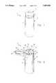
- FIG. 7is an exploded, elevational partial cross-sectional view of the floss dispenser.
- the dispenser 10comprises a cylindrical vial case, generally indicated at 12, having a cylindrical wall 14 with a first open end 16 and a second open end 18 closed by an end plug 20 which is snap fitted to the case 12 in the manner illustrated in FIG. 7.
- a spoolInserted within the case 12 is a spool generally indicated at 22 having a hub 24 around which is wrapped a length of dental floss 26.
- the spool 22is mounted with its axial hub 24 coaxial with the longitudinal axis A of the container (see FIG. 4).
- the hub 24extends beyond the dental floss 26 on either end, thereby forming a lower projection 28 and an upper projection 30.
- the lower projection 28 of the spool hub 24is received within a circular formation 32 formed in the end plug 20 (see FIG. 7).
- the cap 34is removable from the case 12 so as to provide access to the interior of the dispenser 10.
- the cap 34has an arcuate wall 36 with an upwardly-facing surface 38, an inner, downwardly extending annular wall 40 which receives the upper projection 30 of the spool hub 24 therein for centering the hub 24 when the cap 34 is inserted within the opening 16 of the case 12, and an outer, downwardly extending annular wall 42 which engages the cylindrical wall 14 of the case 12.
- the inner annular wall 40which is broadly referred to as "receiving and centering means" has a snug fit with the upper projection 30 of the spool hub 24, but allows the spool to axially rotate so as to pay out floss 26. More particularly, there is another circular formation 44 formed interiorly of the inner annular wall 40 which receives the upper projection 30 of the hub 24 when the cap 34 is mounted on the case 12. The formation 44 is proportioned to provide a close yet unrestrained retention of the projection 30 in such a manner that the spool 22 will spin freely within the cap 34 as floss 26 is dispensed therefrom.
- the cap 34be fabricated from transparent material, such as plastic or glass, so that the floss 26 wrapped around the spool hub 24 can be seen through the top of the dispenser 10. This provides an easy method for a user to determine the amount of floss 26 left within the dispenser 10.
- the end plug 20may be transparent for accomplishing this purpose.
- annular groove 56positioned between the inner and outer annular walls 40, 42. This groove 56 provides sufficient space to allow floss 26 dispensing from the spool hub 24 to pass freely upwardly through the opening 46 in the cap 34. It has been determined that floss 26 will dispense very readily through the opening 46 when the spool hub 24 is retained in the manner described above.
- the positioning of the spool 22 vertically within the case 12 with the floss 26 dispensing off the spool hub 24 and upwardly through the annular groove 56 and into the opening 46avoids the jamming problems previously encountered with top dispense vial floss dispensers where the floss spool is not maintained in a consistent, centered spinning orientation.
- the floss dispenser 10 of the present inventionprovides a smooth, unencumbered floss pay off through its opening 46 in the cap 34.
- the cap 34includes a lid 58 which is hingedly connected to the cap 34 by a pair of hinge elements 60, and movable from a closed position (FIG. 1) to an open position (FIG. 2).
- the lid 58completely seals over the entire top surface 38 of the cap 34 between uses, thoroughly sealing the opening 46, the exposed segment of floss 26, and the blade assembly 48.
- the lid 58may also comprise a thumb tab 62 for assisting the user in hingedly moving the lid 58.
- the lid 58is aligned in such a manner that it hingedly moves away from, and is centered with, a logo or other printed indicia provided on the outer surface of the cylindrical wall 14 of the case 12.
- the cap 34is sometimes too difficult to remove from the case 12, and therefore is not readily adapted for replacing the spool of floss 22 should it become depleted.
- An improvement of the present inventionlies in a means provided for securely attaching the cap 34 to the case 12. More particularly, the cap 34 includes a first interlocking engagement member, generally indicated at 64, which mates with a second interlocking engagement member, generally indicated at 66, of the case 12 (see FIG. 7). The arrangement is such that the cap 34 can only be arranged in one predetermined orientation with respect to the case 12 when the cap 34 is operatively inserted into the first open end 16, and the first engagement member 64 of the cap 34 engages the second engagement member 66 of the case 12.
- the engaging member 66 of the case 12further comprises three stop posts 76, one for each protrusion 70, formed on the inner surface of the wall 14 of the case 12.
- Each stop post 76extends radially inwardly and in a direction generally transverse to the direction of its respective protrusion 70 for engaging its respective protrusion 68 of the cap 34 when rotating the cap to its attached position.
- the stop posts 76are provided for defining a limit when rotating the cap 34.
- an interposed detent element 78which extends radially inwardly a shorter distance than the stop post 76 and in a direction parallel to the direction of the stop post 76. The detent elements 78 prevent the cap 34 from inadvertently loosening and from becoming removed from the case 12.
- the outer edge of the arcuate wall 36 of the capis serrated at 80 to assist the user of the dispenser 10 in attaching and removing the cap 34 from the case.
- serrated edges 80There are two oppositely positioned serrated edges 80 so that the user may grasp the cap 34 with their thumb and forefinger when rotating the cap.
- the end plug 20is press fit into the second open end 18 of the cylindrical wall 14 in a position where it is permanently or substantially permanently attached thereto.
- the clip 50 of the cutting blade assembly 48is inserted into the slot 52 provided in the arcuate wall 36 of the cap 34.
- the spool 22is suitably positioned within the case 12.
- the cap 34is then lowered so that it enters the first open end 16 of the cylindrical wall 14 such that the protrusions 68 of the cap 34 are adjacent the protrusions 70 of the case 12.
- the cap 34is then rotated such that the engaging surfaces 72 of the protrusions 68 of the cap 34 are in engagement with respective engaging surfaces 74 of the protrusions 70 of the case 12.
- the cap 34is rotated until the protrusions 68 engage their respective stop posts 76.
- the detent elements 78assist in preventing the protrusions 68 of the cap 34 from backing out of engagement with the protrusions 70 of the case 12.
- the cap 34is oriented such that when the lid 58 is moved from its closed position to its open position, a logo or other printed indicia is centered with the cap 34.
Landscapes
- Health & Medical Sciences (AREA)
- Dentistry (AREA)
- Epidemiology (AREA)
- Life Sciences & Earth Sciences (AREA)
- Animal Behavior & Ethology (AREA)
- General Health & Medical Sciences (AREA)
- Public Health (AREA)
- Veterinary Medicine (AREA)
- Closures For Containers (AREA)
- Packages (AREA)
- Dental Tools And Instruments Or Auxiliary Dental Instruments (AREA)
Abstract
Description
Claims (10)
Priority Applications (11)
| Application Number | Priority Date | Filing Date | Title |
|---|---|---|---|
| US08/551,503US5607050A (en) | 1995-11-01 | 1995-11-01 | Vial floss dispenser |
| CA002202651ACA2202651A1 (en) | 1995-11-01 | 1996-09-09 | Improved vial floss dispenser |
| PCT/US1996/014405WO1997016131A1 (en) | 1995-11-01 | 1996-09-09 | Improved vial floss dispenser |
| JP9517317AJPH10512181A (en) | 1995-11-01 | 1996-09-09 | Improved vial floss dispenser |
| BR9607075ABR9607075A (en) | 1995-11-01 | 1996-09-09 | Improved bottle dental floss dispenser |
| IL12094596AIL120945A0 (en) | 1995-11-01 | 1996-09-09 | Improved vial floss dispenser |
| EP96929949AEP0800362A1 (en) | 1995-11-01 | 1996-09-09 | Improved vial floss dispenser |
| AU69172/96AAU689394B2 (en) | 1995-11-01 | 1996-09-09 | Improved vial floss dispenser |
| NO972173ANO972173D0 (en) | 1995-11-01 | 1997-05-12 | Improved jar shaped dental floss dispenser |
| FI972578AFI972578A7 (en) | 1995-11-01 | 1997-06-17 | Improved bottle-shaped dental floss dispenser |
| MXPA/A/1997/004932AMXPA97004932A (en) | 1995-11-01 | 1997-06-30 | Best silk distributor bottle |
Applications Claiming Priority (1)
| Application Number | Priority Date | Filing Date | Title |
|---|---|---|---|
| US08/551,503US5607050A (en) | 1995-11-01 | 1995-11-01 | Vial floss dispenser |
Publications (1)
| Publication Number | Publication Date |
|---|---|
| US5607050Atrue US5607050A (en) | 1997-03-04 |
Family
ID=24201546
Family Applications (1)
| Application Number | Title | Priority Date | Filing Date |
|---|---|---|---|
| US08/551,503Expired - LifetimeUS5607050A (en) | 1995-11-01 | 1995-11-01 | Vial floss dispenser |
Country Status (10)
| Country | Link |
|---|---|
| US (1) | US5607050A (en) |
| EP (1) | EP0800362A1 (en) |
| JP (1) | JPH10512181A (en) |
| AU (1) | AU689394B2 (en) |
| BR (1) | BR9607075A (en) |
| CA (1) | CA2202651A1 (en) |
| FI (1) | FI972578A7 (en) |
| IL (1) | IL120945A0 (en) |
| NO (1) | NO972173D0 (en) |
| WO (1) | WO1997016131A1 (en) |
Cited By (24)
| Publication number | Priority date | Publication date | Assignee | Title |
|---|---|---|---|---|
| US5806666A (en)* | 1997-06-18 | 1998-09-15 | Gillette Canada Inc. | Dental floss container |
| US6253774B1 (en)* | 1999-12-27 | 2001-07-03 | Robert F. Mason | Compact dental flossing tool |
| US20030140939A1 (en)* | 2002-01-30 | 2003-07-31 | Nudo Alexander S. | Dental cleaning tool |
| US6688607B2 (en) | 1997-04-18 | 2004-02-10 | Henkel Loctite Corporation | Material for sealing threaded pipe joints, and dispenser therefor |
| USD508148S1 (en) | 2003-01-08 | 2005-08-02 | Alexander S. Nudo | Dental cleaning tool |
| US20060086369A1 (en)* | 2004-10-26 | 2006-04-27 | Wilkinson William T | Toothbrush and flossing system |
| US20060196909A1 (en)* | 2003-04-11 | 2006-09-07 | Hadtke Frederick B | Novel device |
| US20060248670A1 (en)* | 2005-02-10 | 2006-11-09 | Dr. Fresh, Inc. | Toothbrush having flossing dispenser on handle and method for using same |
| US20070084954A1 (en)* | 2005-09-14 | 2007-04-19 | James Lyman | Thread spool and cap |
| US20070181446A1 (en)* | 2006-02-06 | 2007-08-09 | Donahoe Ryan M | Medical implant package |
| US20070209953A1 (en)* | 2006-03-31 | 2007-09-13 | Frank Conte | Dental Floss Dispensing Device |
| US20080093374A1 (en)* | 2006-10-20 | 2008-04-24 | Sr Pack Ind. Comercio Ltda | Dispensing package |
| US20080173643A1 (en)* | 2007-01-16 | 2008-07-24 | Wadsworth Edward G | Thread caddy system |
| US20080190787A1 (en)* | 2005-03-15 | 2008-08-14 | Grosse Ted K | Hygienic dental floss |
| US20100269850A1 (en)* | 2007-11-14 | 2010-10-28 | Souza Nilson Altair De | Oral hygiene case with dental floss lid compartment |
| US20130341365A1 (en)* | 2012-05-30 | 2013-12-26 | Patrick C. Ryan | Multiport valved dispenser for toothpaste and the like |
| US20150245893A1 (en)* | 2014-03-03 | 2015-09-03 | Christopher Edwin Kelchlin | Multipurpose filament dispensing device |
| US20160264376A1 (en)* | 2015-03-10 | 2016-09-15 | Christopher A. Rodgers | Rapid rope |
| US20200155283A1 (en)* | 2018-11-19 | 2020-05-21 | Gagik Virabyan | Sanitary portable single-use dental floss device |
| US10889739B2 (en) | 2015-01-16 | 2021-01-12 | Henkel IP & Holding GmbH | Sealant material |
| US11066587B2 (en) | 2015-01-16 | 2021-07-20 | Henkel IP & Holding GmbH | Sealant material |
| US20220226082A1 (en)* | 2021-01-19 | 2022-07-21 | Erin Wood | Dissolving Gingival Retraction Cord Apparatus |
| US11413124B1 (en)* | 2021-06-15 | 2022-08-16 | David C. Serrell | Integrated manual toothbrush assembly comprising in interior dental floss compartment |
| US11583359B2 (en)* | 2019-07-03 | 2023-02-21 | A. Raymond Et Cie | Double packaging for object intended to remain sterile |
Families Citing this family (4)
| Publication number | Priority date | Publication date | Assignee | Title |
|---|---|---|---|---|
| DE102005037202A1 (en)* | 2005-08-06 | 2007-02-08 | Synpart Ag | Dentifrice container |
| USD677837S1 (en) | 2011-05-02 | 2013-03-12 | Colgate-Palmolive Company | Container for dental floss |
| JP7283969B2 (en)* | 2019-04-26 | 2023-05-30 | サンスター株式会社 | interdental cleaner |
| JP7372049B2 (en)* | 2019-04-26 | 2023-10-31 | サンスター株式会社 | Interdental cleaning tool |
Citations (19)
| Publication number | Priority date | Publication date | Assignee | Title |
|---|---|---|---|---|
| US817050A (en)* | 1906-01-18 | 1906-04-03 | Johnson & Johnson | Dental-floss holder. |
| US1454429A (en)* | 1922-11-25 | 1923-05-08 | Frank G Dresser | Dental floss dispenser |
| US2340184A (en)* | 1943-08-23 | 1944-01-25 | Gray John | Spool holder |
| US2853082A (en)* | 1955-09-23 | 1958-09-23 | Leroy E Nelson | Dental floss holder |
| US2929541A (en)* | 1956-05-22 | 1960-03-22 | Johnson & Johnson | Dispenser for dental floss and other filaments |
| US3246815A (en)* | 1964-09-02 | 1966-04-19 | Woltra Company Inc | Dental floss dispenser |
| US3480190A (en)* | 1967-07-07 | 1969-11-25 | Hyman Freedman | Dental floss container and dispenser |
| US3890986A (en)* | 1973-04-29 | 1975-06-24 | Den Tal Ez Mfg Co | Teeth cleaning unit |
| US4111089A (en)* | 1976-12-09 | 1978-09-05 | Elio Montaruli | Refillable cutting dispenser |
| US4162688A (en)* | 1977-09-07 | 1979-07-31 | John O. Butler Company | Medicating floss dispenser and method of applying medication to human teeth |
| USD271431S (en) | 1979-08-20 | 1983-11-15 | Colgate-Palmolive Company | Dental floss container |
| US4546782A (en)* | 1984-07-09 | 1985-10-15 | Kucher Carl J | Combination toothpick, gum massager, and dental floss holder |
| US4706843A (en)* | 1986-11-07 | 1987-11-17 | Thornton Theodore W | Dispensing chain of loop lengths of dental floss or the like and method of forming same |
| US4796783A (en)* | 1987-08-10 | 1989-01-10 | Paulson Ralph E | Dental floss dispenser |
| US4934389A (en)* | 1988-12-06 | 1990-06-19 | Pettiford William L | Dental floss dispenser |
| WO1991013594A1 (en)* | 1990-03-05 | 1991-09-19 | Chari Srinivas R | Apparatus for and method of dispensing dental floss |
| US5156311A (en)* | 1992-02-21 | 1992-10-20 | W. L. Gore & Associates, Inc. | Dental floss dispenser |
| USD339215S (en) | 1992-02-12 | 1993-09-07 | W. L. Gore & Associates, Inc. | Dental floss dispenser |
| USD339426S (en) | 1992-02-12 | 1993-09-14 | W. L. Gore & Associates, Inc. | Dental floss dispenser |
Family Cites Families (1)
| Publication number | Priority date | Publication date | Assignee | Title |
|---|---|---|---|---|
| US4073419A (en)* | 1976-04-19 | 1978-02-14 | John O. Butler Company | Thread storage and dispensing system |
- 1995
- 1995-11-01USUS08/551,503patent/US5607050A/ennot_activeExpired - Lifetime
- 1996
- 1996-09-09EPEP96929949Apatent/EP0800362A1/ennot_activeWithdrawn
- 1996-09-09JPJP9517317Apatent/JPH10512181A/enactivePending
- 1996-09-09CACA002202651Apatent/CA2202651A1/ennot_activeAbandoned
- 1996-09-09AUAU69172/96Apatent/AU689394B2/ennot_activeCeased
- 1996-09-09BRBR9607075Apatent/BR9607075A/ennot_activeApplication Discontinuation
- 1996-09-09ILIL12094596Apatent/IL120945A0/enunknown
- 1996-09-09WOPCT/US1996/014405patent/WO1997016131A1/ennot_activeApplication Discontinuation
- 1997
- 1997-05-12NONO972173Apatent/NO972173D0/enunknown
- 1997-06-17FIFI972578Apatent/FI972578A7/ennot_activeApplication Discontinuation
Patent Citations (20)
| Publication number | Priority date | Publication date | Assignee | Title |
|---|---|---|---|---|
| US817050A (en)* | 1906-01-18 | 1906-04-03 | Johnson & Johnson | Dental-floss holder. |
| US1454429A (en)* | 1922-11-25 | 1923-05-08 | Frank G Dresser | Dental floss dispenser |
| US2340184A (en)* | 1943-08-23 | 1944-01-25 | Gray John | Spool holder |
| US2853082A (en)* | 1955-09-23 | 1958-09-23 | Leroy E Nelson | Dental floss holder |
| US2929541A (en)* | 1956-05-22 | 1960-03-22 | Johnson & Johnson | Dispenser for dental floss and other filaments |
| US3246815A (en)* | 1964-09-02 | 1966-04-19 | Woltra Company Inc | Dental floss dispenser |
| US3480190A (en)* | 1967-07-07 | 1969-11-25 | Hyman Freedman | Dental floss container and dispenser |
| US3890986A (en)* | 1973-04-29 | 1975-06-24 | Den Tal Ez Mfg Co | Teeth cleaning unit |
| US4111089A (en)* | 1976-12-09 | 1978-09-05 | Elio Montaruli | Refillable cutting dispenser |
| US4162688A (en)* | 1977-09-07 | 1979-07-31 | John O. Butler Company | Medicating floss dispenser and method of applying medication to human teeth |
| USD271431S (en) | 1979-08-20 | 1983-11-15 | Colgate-Palmolive Company | Dental floss container |
| US4546782A (en)* | 1984-07-09 | 1985-10-15 | Kucher Carl J | Combination toothpick, gum massager, and dental floss holder |
| US4706843A (en)* | 1986-11-07 | 1987-11-17 | Thornton Theodore W | Dispensing chain of loop lengths of dental floss or the like and method of forming same |
| US4796783A (en)* | 1987-08-10 | 1989-01-10 | Paulson Ralph E | Dental floss dispenser |
| US4934389A (en)* | 1988-12-06 | 1990-06-19 | Pettiford William L | Dental floss dispenser |
| WO1991013594A1 (en)* | 1990-03-05 | 1991-09-19 | Chari Srinivas R | Apparatus for and method of dispensing dental floss |
| US5076302A (en)* | 1990-03-05 | 1991-12-31 | Chari Srinivas R | Apparatus for and method of dispensing dental floss |
| USD339215S (en) | 1992-02-12 | 1993-09-07 | W. L. Gore & Associates, Inc. | Dental floss dispenser |
| USD339426S (en) | 1992-02-12 | 1993-09-14 | W. L. Gore & Associates, Inc. | Dental floss dispenser |
| US5156311A (en)* | 1992-02-21 | 1992-10-20 | W. L. Gore & Associates, Inc. | Dental floss dispenser |
Cited By (41)
| Publication number | Priority date | Publication date | Assignee | Title |
|---|---|---|---|---|
| US7168707B2 (en) | 1997-04-18 | 2007-01-30 | Loctite (R&D) Limited | Method for sealing threaded pipe joints |
| US6688607B2 (en) | 1997-04-18 | 2004-02-10 | Henkel Loctite Corporation | Material for sealing threaded pipe joints, and dispenser therefor |
| US20040070154A1 (en)* | 1997-04-18 | 2004-04-15 | Loctite (R&D) Limited | Method for sealing threaded pipe joints |
| US5806666A (en)* | 1997-06-18 | 1998-09-15 | Gillette Canada Inc. | Dental floss container |
| US6253774B1 (en)* | 1999-12-27 | 2001-07-03 | Robert F. Mason | Compact dental flossing tool |
| US20030140939A1 (en)* | 2002-01-30 | 2003-07-31 | Nudo Alexander S. | Dental cleaning tool |
| US6997191B2 (en) | 2002-01-30 | 2006-02-14 | Nudo Sr Alexander S | Dental cleaning tool |
| USD508148S1 (en) | 2003-01-08 | 2005-08-02 | Alexander S. Nudo | Dental cleaning tool |
| US20060196909A1 (en)* | 2003-04-11 | 2006-09-07 | Hadtke Frederick B | Novel device |
| US8015982B2 (en) | 2004-10-26 | 2011-09-13 | Wilkinson William T | Toothbrush and flossing system |
| US20060086369A1 (en)* | 2004-10-26 | 2006-04-27 | Wilkinson William T | Toothbrush and flossing system |
| US20060248670A1 (en)* | 2005-02-10 | 2006-11-09 | Dr. Fresh, Inc. | Toothbrush having flossing dispenser on handle and method for using same |
| US7201172B2 (en)* | 2005-02-10 | 2007-04-10 | Dr. Fresh, Inc. | Toothbrush having flossing dispenser on handle |
| US20080190787A1 (en)* | 2005-03-15 | 2008-08-14 | Grosse Ted K | Hygienic dental floss |
| US7987861B2 (en)* | 2005-03-15 | 2011-08-02 | Grosse Ted K | Hygienic dental floss |
| US20070084954A1 (en)* | 2005-09-14 | 2007-04-19 | James Lyman | Thread spool and cap |
| US7438010B2 (en)* | 2005-09-14 | 2008-10-21 | Hemingworth, Inc. | Thread spool and cap |
| US20090065376A1 (en)* | 2006-02-06 | 2009-03-12 | Donahoe Ryan M | Medical implant package |
| US7451870B2 (en) | 2006-02-06 | 2008-11-18 | Zimmer Dental, Inc. | Medical implant package with a cap having a cavity |
| US7770722B2 (en) | 2006-02-06 | 2010-08-10 | Zimmer Dental, Inc. | Dental implant package including a plug |
| US20070181446A1 (en)* | 2006-02-06 | 2007-08-09 | Donahoe Ryan M | Medical implant package |
| US20070209953A1 (en)* | 2006-03-31 | 2007-09-13 | Frank Conte | Dental Floss Dispensing Device |
| US20080093374A1 (en)* | 2006-10-20 | 2008-04-24 | Sr Pack Ind. Comercio Ltda | Dispensing package |
| US7997444B2 (en)* | 2006-10-20 | 2011-08-16 | Sr Pack Ind. Comercio Ltda | Dispensing package |
| US20080173643A1 (en)* | 2007-01-16 | 2008-07-24 | Wadsworth Edward G | Thread caddy system |
| US20100269850A1 (en)* | 2007-11-14 | 2010-10-28 | Souza Nilson Altair De | Oral hygiene case with dental floss lid compartment |
| US8251076B2 (en)* | 2007-11-14 | 2012-08-28 | Souza Nilson Altair De | Oral hygiene case with dental floss lid compartment |
| US20130341365A1 (en)* | 2012-05-30 | 2013-12-26 | Patrick C. Ryan | Multiport valved dispenser for toothpaste and the like |
| US20150245893A1 (en)* | 2014-03-03 | 2015-09-03 | Christopher Edwin Kelchlin | Multipurpose filament dispensing device |
| US9498311B2 (en)* | 2014-03-03 | 2016-11-22 | Christopher Edwin Kelchlin | Multipurpose filament dispensing device |
| US10889739B2 (en) | 2015-01-16 | 2021-01-12 | Henkel IP & Holding GmbH | Sealant material |
| US11066587B2 (en) | 2015-01-16 | 2021-07-20 | Henkel IP & Holding GmbH | Sealant material |
| US20160264376A1 (en)* | 2015-03-10 | 2016-09-15 | Christopher A. Rodgers | Rapid rope |
| US10577218B2 (en)* | 2015-03-10 | 2020-03-03 | Christopher A. Rodgers | Rapid rope |
| US20220227601A1 (en)* | 2015-03-10 | 2022-07-21 | Christopher A. Rodgers | Rapid rope |
| US11679954B2 (en)* | 2015-03-10 | 2023-06-20 | Rapid-Rope Llc | Rapid rope |
| US20200155283A1 (en)* | 2018-11-19 | 2020-05-21 | Gagik Virabyan | Sanitary portable single-use dental floss device |
| US11071611B2 (en)* | 2018-11-19 | 2021-07-27 | Gagik Virabyan | Sanitary portable single-use dental floss device |
| US11583359B2 (en)* | 2019-07-03 | 2023-02-21 | A. Raymond Et Cie | Double packaging for object intended to remain sterile |
| US20220226082A1 (en)* | 2021-01-19 | 2022-07-21 | Erin Wood | Dissolving Gingival Retraction Cord Apparatus |
| US11413124B1 (en)* | 2021-06-15 | 2022-08-16 | David C. Serrell | Integrated manual toothbrush assembly comprising in interior dental floss compartment |
Also Published As
| Publication number | Publication date |
|---|---|
| AU6917296A (en) | 1997-05-22 |
| NO972173L (en) | 1997-05-12 |
| BR9607075A (en) | 1997-11-18 |
| IL120945A0 (en) | 1997-09-30 |
| FI972578A0 (en) | 1997-06-17 |
| FI972578A7 (en) | 1997-06-17 |
| EP0800362A1 (en) | 1997-10-15 |
| MX9704932A (en) | 1997-10-31 |
| NO972173D0 (en) | 1997-05-12 |
| AU689394B2 (en) | 1998-03-26 |
| CA2202651A1 (en) | 1997-05-02 |
| JPH10512181A (en) | 1998-11-24 |
| WO1997016131A1 (en) | 1997-05-09 |
Similar Documents
| Publication | Publication Date | Title |
|---|---|---|
| US5607050A (en) | Vial floss dispenser | |
| AU676394B2 (en) | Improved vial floss dispenser | |
| US5076302A (en) | Apparatus for and method of dispensing dental floss | |
| US5732722A (en) | Cap for a toothpaste container having an incorporated spool of dental floss | |
| US5662239A (en) | Medicinal container with complete instructions | |
| US8381743B1 (en) | Combined toothpaste container cap dental floss dispenser | |
| EP0531394A1 (en) | CONTAINER FOR DISPENSING TABLET. | |
| US20070137454A1 (en) | Dispenser for web material | |
| RU2503598C2 (en) | Container with hinged lid | |
| US4399914A (en) | Pilfer resistant container | |
| US4880020A (en) | Traveling toothbrush holder | |
| US4550857A (en) | Cotton swab vender | |
| US5152428A (en) | Tank with connecting union and a cutting blade | |
| US6047712A (en) | Floss dispenser | |
| EP2938557B1 (en) | Combination child-resistant package and collapsible tube, and method of using same | |
| CA2065505C (en) | Drain cleaner dispenser with locking means | |
| US3693844A (en) | Discharge means for particulate matter dispenser | |
| US4226335A (en) | Device for dispensing fish eggs | |
| MXPA97004932A (en) | Best silk distributor bottle | |
| US6561371B2 (en) | Self sealing cap | |
| US20050000538A1 (en) | Combination key holder and sanitary dental floss dispenser | |
| KR200317687Y1 (en) | Container capable separately keeping and mixing two contents having a different ingredient | |
| US5931344A (en) | Wall mountable product dispenser | |
| US20050263431A1 (en) | Dispensing package for flowable product | |
| JP2596855Y2 (en) | Liquid dispense container |
Legal Events
| Date | Code | Title | Description |
|---|---|---|---|
| AS | Assignment | Owner name:W.L. GORE & ASSOCIATES, INC., DELAWARE Free format text:ASSIGNMENT OF ASSIGNORS INTEREST;ASSIGNORS:DOLAN, JOHN W.;SPENCER, JOHN W., JR.;HILL, RICKEY I.;AND OTHERS;REEL/FRAME:007895/0198;SIGNING DATES FROM 19960125 TO 19960131 | |
| STCF | Information on status: patent grant | Free format text:PATENTED CASE | |
| AS | Assignment | Owner name:GORE ENTERPRISE HOLDINGS, INC., DELAWARE Free format text:ASSIGNMENT OF ASSIGNORS INTEREST;ASSIGNOR:W.L. GORE & ASSOCIATES, INC.;REEL/FRAME:010175/0437 Effective date:19990825 | |
| FEPP | Fee payment procedure | Free format text:PAYOR NUMBER ASSIGNED (ORIGINAL EVENT CODE: ASPN); ENTITY STATUS OF PATENT OWNER: LARGE ENTITY | |
| FPAY | Fee payment | Year of fee payment:4 | |
| FPAY | Fee payment | Year of fee payment:8 | |
| FEPP | Fee payment procedure | Free format text:PAYOR NUMBER ASSIGNED (ORIGINAL EVENT CODE: ASPN); ENTITY STATUS OF PATENT OWNER: LARGE ENTITY | |
| AS | Assignment | Owner name:PROCTER & GAMBLE COMPANY, THE, OHIO Free format text:ASSIGNMENT OF ASSIGNORS INTEREST;ASSIGNORS:C.B. JONES FOR W.L. GORE & ASSOCIATES, INC.;JOHN S. CAMPBELL FOR GORE ENTERPRISE HOLDINGS, INC.;REEL/FRAME:017230/0369 Effective date:20031015 Owner name:PROCTER & GAMBLE COMPANY, THE, OHIO Free format text:ASSIGNMENT OF ASSIGNORS INTEREST;ASSIGNORS:JONES, C.B.;CAMPBELL, JOHN S.;REEL/FRAME:017537/0063 Effective date:20031015 | |
| FPAY | Fee payment | Year of fee payment:12 | |
| AS | Assignment | Owner name:W. L. GORE & ASSOCIATES, INC., DELAWARE Free format text:ASSIGNMENT OF ASSIGNORS INTEREST;ASSIGNOR:GORE ENTERPRISE HOLDINGS, INC.;REEL/FRAME:027906/0508 Effective date:20120130 | |
| AS | Assignment | Owner name:W. L. GORE & ASSOCIATES, INC., DELAWARE Free format text:NULLIFICATION TO VOID PROPERTY NUMBERS RECORDED ON REEL 027906 FRAME 0508 THAT WERE NOT OWNED BY THE CONVEYING PARTY INDICATED ON THE RECORDATION COVER SHEET;ASSIGNOR:GORE ENTERPRISE HOLDINGS, INC.;REEL/FRAME:028214/0098 Effective date:20120130 |