US5606988A - Connector assembly for ink cartridge - Google Patents
Connector assembly for ink cartridgeDownload PDFInfo
- Publication number
- US5606988A US5606988AUS08/192,083US19208394AUS5606988AUS 5606988 AUS5606988 AUS 5606988AUS 19208394 AUS19208394 AUS 19208394AUS 5606988 AUS5606988 AUS 5606988A
- Authority
- US
- United States
- Prior art keywords
- passageway
- fitment
- coupler
- valve
- connector assembly
- Prior art date
- Legal status (The legal status is an assumption and is not a legal conclusion. Google has not performed a legal analysis and makes no representation as to the accuracy of the status listed.)
- Expired - Lifetime
Links
- 239000000463materialSubstances0.000claimsdescription11
- 239000007788liquidSubstances0.000claimsdescription7
- 239000012530fluidSubstances0.000claimsdescription6
- 238000003780insertionMethods0.000claimsdescription2
- 230000037431insertionEffects0.000claimsdescription2
- 239000004033plasticSubstances0.000claimsdescription2
- 229920003023plasticPolymers0.000claimsdescription2
- 229920000642polymerPolymers0.000description4
- -1but not limited toSubstances0.000description3
- 239000004698PolyethyleneSubstances0.000description2
- 239000000853adhesiveSubstances0.000description2
- 230000001070adhesive effectEffects0.000description2
- 239000000919ceramicSubstances0.000description2
- 229920001903high density polyethylenePolymers0.000description2
- 239000004700high-density polyethyleneSubstances0.000description2
- 239000002184metalSubstances0.000description2
- 239000000123paperSubstances0.000description2
- 229920000573polyethylenePolymers0.000description2
- 230000003014reinforcing effectEffects0.000description2
- 238000007789sealingMethods0.000description2
- 239000011800void materialSubstances0.000description2
- 230000004075alterationEffects0.000description1
- 230000000694effectsEffects0.000description1
- 239000013013elastic materialSubstances0.000description1
- 238000000605extractionMethods0.000description1
- 239000011521glassSubstances0.000description1
- 239000012858resilient materialSubstances0.000description1
- 229910001220stainless steelInorganic materials0.000description1
- 239000010935stainless steelSubstances0.000description1
- 238000006467substitution reactionMethods0.000description1
Images

Classifications
- B—PERFORMING OPERATIONS; TRANSPORTING
- B41—PRINTING; LINING MACHINES; TYPEWRITERS; STAMPS
- B41J—TYPEWRITERS; SELECTIVE PRINTING MECHANISMS, i.e. MECHANISMS PRINTING OTHERWISE THAN FROM A FORME; CORRECTION OF TYPOGRAPHICAL ERRORS
- B41J2/00—Typewriters or selective printing mechanisms characterised by the printing or marking process for which they are designed
- B41J2/005—Typewriters or selective printing mechanisms characterised by the printing or marking process for which they are designed characterised by bringing liquid or particles selectively into contact with a printing material
- B41J2/01—Ink jet
- B41J2/17—Ink jet characterised by ink handling
- B41J2/175—Ink supply systems ; Circuit parts therefor
- B41J2/17503—Ink cartridges
- B41J2/1752—Mounting within the printer
- B41J2/17523—Ink connection
- B—PERFORMING OPERATIONS; TRANSPORTING
- B41—PRINTING; LINING MACHINES; TYPEWRITERS; STAMPS
- B41J—TYPEWRITERS; SELECTIVE PRINTING MECHANISMS, i.e. MECHANISMS PRINTING OTHERWISE THAN FROM A FORME; CORRECTION OF TYPOGRAPHICAL ERRORS
- B41J2/00—Typewriters or selective printing mechanisms characterised by the printing or marking process for which they are designed
- B41J2/005—Typewriters or selective printing mechanisms characterised by the printing or marking process for which they are designed characterised by bringing liquid or particles selectively into contact with a printing material
- B41J2/01—Ink jet
- B41J2/17—Ink jet characterised by ink handling
- B41J2/175—Ink supply systems ; Circuit parts therefor
- Y—GENERAL TAGGING OF NEW TECHNOLOGICAL DEVELOPMENTS; GENERAL TAGGING OF CROSS-SECTIONAL TECHNOLOGIES SPANNING OVER SEVERAL SECTIONS OF THE IPC; TECHNICAL SUBJECTS COVERED BY FORMER USPC CROSS-REFERENCE ART COLLECTIONS [XRACs] AND DIGESTS
- Y10—TECHNICAL SUBJECTS COVERED BY FORMER USPC
- Y10T—TECHNICAL SUBJECTS COVERED BY FORMER US CLASSIFICATION
- Y10T137/00—Fluid handling
- Y10T137/1624—Destructible or deformable element controlled
- Y10T137/1632—Destructible element
- Y10T137/1654—Separable valve coupling or conduit
Definitions
- the present inventionis directed to a connector assembly for conducting ink to and from a supply cartridge.
- the ink cartridgeWhen the ink cartridge has been depleted of ink, it is replaced or refilled. Sometimes, it is necessary to disconnect a partially filled or filled ink cartridge from the tube. For example, it may be desirable to remove a partially filled cartridge before a large print job and replace it with a filled cartridge to prevent interruptions during printing due to insufficient ink supply. It may be difficult to disconnect partially filled or filled ink cartridges without leaking ink from the cartridge.
- Some ink cartridgesare constructed to be collapsed, i.e., the volume of the cartridge is reduced, as ink is withdrawn from the ink cartridge by the pen.
- Collapsible ink cartridgesmay be overfilled during refilling because certain portions of the ink cartridge are permanently deformed when the cartridge is collapsed. The permanent deformation prevents the ink cartridge from returning to its original size when refilled with ink. Accordingly, attempting to refill the deformed cartridge with the same volume of ink as originally held may cause the ink to overflow and expose the user to free ink.
- the present inventionis directed to a connector assembly that facilitates convenient disconnection of a filled or partially filled ink cartridge from a pen reservoir.
- the connector assemblyincludes a valve assembly having a fitment for connecting the ink cartridge to a coupler that is in fluid communication with a pen reservoir.
- the valve assemblyhas a central passageway formed therethrough and includes a valve movable between a closed position for occluding the passageway and an open position to open the passageway.
- the coupleris insertable into the passageway for moving the valve from the closed to the open position to permit ink flow through the passageway.
- An apertureis formed through the coupler so that ink may flow from the ink cartridge to the print head.
- the valveis biased into the closed position when the ink cartridge is disconnected, thereby to prevent spillage of ink.
- the connector assemblyalso includes a spherical stopper for obstructing the central passageway of the fitment to provide extra protection against leaks.
- the connector assembly and ink cartridgeare made of a recyclable material.
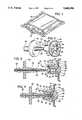
- FIG. 1is a perspective view of a cartridge employing one embodiment of a valve assembly of the present invention.
- FIG. 2is an enlarged perspective view of the primary components of a connector assembly.
- FIG. 3is a sectional side view of components illustrated in FIG. 2, showing the components disconnected.
- FIG. 5is a sectional view of an alternate embodiment of a connector assembly.
- FIG. 6is a sectional view of another embodiment of a connector assembly.
- FIG. 7is a sectional view of yet another embodiment of a connector assembly.
- FIG. 8is a sectional view of still another embodiment of a connector assembly.
- a connector assembly 20 of the present inventionincludes a valve assembly 22 and an elongated coupler 26 to permit extraction of ink from a supply container, such as an ink cartridge 24, when the coupler 26 and valve assembly 22 are connected.
- the couplermay also be connected to a tube leading to the reservoir of an ink-jet pen (not shown) so that ink may be conveyed from ink cartridge 24 to the pen.
- Connector assembly 20enables a filled or partially filled ink cartridge 24 to be removed from coupler 26 without ink leakage.
- Ink cartridge 24may be made from any of a variety of materials including, but not limited to, polymer, metal, glass and paper based materials.
- One preferred embodiment of cartridge 24is made of a recyclable material such as high density polyethylene. Other recyclable and non-recyclable materials, or combinations thereof may be used.
- Cartridge 24is preferably, but not necessarily, collapsible so that the cartridge is gradually collapsed as the cartridge is depleted of ink.
- the valve assembly 22includes a fitment 23 and valve 40.
- the fitment 23includes a central bore or passageway 28 through which ink may pass from the container 24.
- the fitment 23is integrally formed with the cartridge 24 so that ink contained in the cartridge may be discharged through the fitment 23 without any leakage between the fitment and cartridge 24.
- fitment 23may be a separate body that is operatively attached to cartridge 24 to provide a seal therebetween that is impermeable to ink.
- the fitment passageway 28has an inlet end 30 and an outlet end 32.
- the ends 30, 32have chamfered seats 34, 36 respectively.
- the passagewaymay be constructed without chamfered seats.
- valve 40is movable between a closed position (FIG. 3) for occluding the passageway 28 and an open position (FIG. 4) to open the passageway 28.
- Valve 40includes a cone shaped plug 42 and a connected biasing member, such as a resilient spring 44.
- Spring 44is generally disk-shaped, and has apertures 52 formed through it to permit ink to flow through the spring.
- spring 44is sealingly attached to an inside wall 53 of cartridge 24 or fitment 23 to prevent undesirable leakage. The spring normally biases plug 42 toward the closed position.
- Plug 42is preferably, but not necessarily, integrally formed with spring 44 to protrude from a center 46 of one side of the spring.
- the plug and the springmay be made of an elastic material such as rubber, plastic or any other resilient material that seals well against the passageway 28.
- plug 42may be separately formed and attached to the center 46 of the spring by fastening means such as adhesives or mechanical fasteners.
- Plug 42has a conical projection 47 terminating at a flat bottom contact surface 48. The projection rests against chamfered seat 34 when valve 40 is in the closed position to occlude inlet end 30 of passageway 28. Plug 42 is in the open position when the plug is moved away from chamfered seat 34 so that the plug is spaced apart from seat 34 and a generally annular void 50 is formed between plug 42, and fitment 23 (FIG. 4). In the open position, therefore, a continuous liquid path exits from the container interior, through spring apertures 52, void 50, and to passageway 28.
- Coupler 26may be made of any of a variety of materials including, but not limited to, metal, polymer and ceramics.
- the illustrated embodiment of the coupleris made of a polymer such as polyethylene. However, other materials such as stainless steel and ceramics may be used.
- Coupler 26is elongated and includes an annular handle member 54 having a valve opener portion 56 extending from one side and tub connector portion 58 extending from the other side.
- the tube connector portion 58may be used for connecting coupler 26 to a tube or other conduit that connects with the pen (not shown).
- Valve opener portion 56may be tapered in stepped fashion as shown, or in a continuous manner.
- Valve opener portion 56has an end tip 60 that is sufficiently narrow to be insertable into fitment passageway 28. End tip 60 terminates at a transverse end surface 62 that abuts contact surface 48 of plug 42 when valve opener portion 56 is inserted for a sufficient distance into fitment passageway 28. Insertion of portion 56 displaces the plug 42 to open the valve 40.
- the shape of the tapered valve opener portion 56limits the distance into which the portion 56 may be inserted, thereby to prevent end tip 60 from pushing the plug 42 too far away from chamfered seat 34, which may break the spring 44.
- the fit of the connector and fitmentprovides a fluid-tight seal between those components.
- the resilience of the polyethylene fitmentprovides this sealing effect without the need for a gasket. Consequently, the outlet end 32 (and inlet end 30) of the fitment define an integral, annular seal for leak-free sealing against a component, such as the coupler 26, that is inserted therein.
- a common central aperture 65extends completely through the tube connector portion 58 and opener portion 56 to the tip 60 at the valve opener portion 56.
- Adjacent end tip 60is a transverse aperture 64 formed to be in fluid communication with the end of central aperture 65. Accordingly, ink may flow through apertures 64, 65 from end tip 60 through coupler 26 and exit at tube connector portion 58.
- a breakable septum 38extends across passageway 28 of the fitment between inlet end 30 and outlet end 32 to provide leak protection, such as during shipping of the cartridge. Specifically, the septum provides redundant leak protection with the normally closed valve 40. Septum 38 is preferably made of a material that is strong enough to prevent ink from flowing through passageway 28, yet sufficiently fragile to break when coupler 26 is inserted into passageway 28 to pierce the septum.
- the valve assembly 22may include a removable spherical shaped stopper 66 for tightly stopping the passageway 28 to ensure the passageway remains occluded.
- the stopper 66may be integrally formed with fitment 23.
- stopper 66is heat welded or heat staked to an edge of fitment 23 adjacent the outlet end 32 of passageway 28. The stopper is easily removed from fitment 23 and may be inserted in passageway 28 to obstruct the passageway after coupler 26 is removed therefrom.
- stopper 66may provide leak protection when coupler 26 is removed from passageway 28 after septum 38 has been broken.
- Stopper 66may be made of a material different from the material used for the fitment and the stopper may be attached to or supported by a structure independent of fitment 23.
- a coupler 67includes a holding mechanism such as hinge-supported latches 68 for holding coupler 67 to an annular flange 69 of a fitment 70.
- the latchesensure a seal-tight connection between coupler 67 and fitment 70.
- Coupler 67may be released from fitment 70 by disengaging latch 68 (dashed lines) from annual flange 69.
- FIG. 6shows an alternative fitment 71 having an annular reinforcing element 72 extending between a mid-portion 74 and ink cartridge 24. Reinforcing member 72 reinforces fitment 71 and reduces the risk of fitment 71 breaking when the coupler is inserted and removed from a passageway 76 formed through fitment 71.
- FIG. 8shows an alternative fitment 80 having a transverse aperture 82 extending therethrough.
- Transverse aperture 82has an outlet end portion 84 and an opposite stopper retaining end portion 86.
- Outlet end portion 84has an outwardly chamfered portion 88 adapted to permit coupler 26 to be inserted a predetermined distance into transverse aperture 82.
- Outlet end portion 84may have a breakable septum 89 extending across the transverse aperture to prevent accidental leakage of ink from the cartridge. As described above, the septum is pierced when coupler 26 is inserted into transverse aperture 82.
- Stopper retaining portion 86is dimensioned to sealingly hold a movable stopper 92 to prevent ink from flowing through stopper retaining end portion 86.
- Stopper 92is preferably made of a polymer such as high density polyethylene.
- a central portion 87 of transverse aperture 82is disposed between end portions 84, 86 and has a pocket 89 formed therein.
- a central longitudinal aperture 90is formed within fitment 80 and is substantially perpendicular to transverse aperture 82. Central aperture 90 intersects, and is in fluid communication with, aperture 82 at central portion 87.
- the aperture 90has and an inlet portion 91 adjacent cartridge 24 so that ink may flow from the cartridge in through inlet portion 91 of central aperture 90 and out through outlet end portion 84.
- the fitment 80is adapted for use with a valve, such as valve 40 (FIG. 2).
- stopper 92When coupler 26 is withdrawn from aperture 82, stopper 92 may be moved, such as by pushing the stopper from end portion 86 as indicated by an arrow 83, to rest between pocket 89 and central aperture 90 to plug central aperture 90. To re-open aperture 90, the stopper may be pushed back into end portion 86.
- FIG. 7illustrates an alternative fitment 100 having a longitudinal passageway 102 extending between an inlet end 104 of cartridge 24 and a transverse elongated chamber 108 defined within fitment 100.
- the fitmentalso has an off-center outlet passageway 110 formed therein in fluid communication with chamber 108 so that fluid may flow from cartridge 24 through passageway 102 and chamber 108 and be discharged through outlet passageway 110.
- the fitment 100is adapted for use with a valve, such as valve 40 (FIG. 2).
- Outlet passageway 110may have an outwardly tapered end portion 118 that permits the tapered coupler 26 to be inserted a pre-determined distance until the coupler seals the inlet passageway.
- Outlet passageway 110may include a breakable septum 112, similar to the septum described above.
- Fitment 100also defines a stopper-holding aperture 114 that is concentric with passageway 102 for holding a removable stopper 116 that is integrally molded with the fitment, or heat staked therein. Stopper 116 may be, alternatively, attached within central aperture 114 by an adhesive or mechanical fastener.
- Central aperture 114is preferably aligned to intersect with central inlet passageway 102 so that stopper 116 may be inserted into inlet passageway 102 by pushing stopper 116 across chamber 108 into inlet passageway 102. In the illustrated embodiment, the stopper may be pushed into central inlet passageway 102 without first removing coupler 26 from outlet passageway 110.
Landscapes
- Ink Jet (AREA)
- Recording Measured Values (AREA)
- Containers And Packaging Bodies Having A Special Means To Remove Contents (AREA)
Abstract
Description
The present invention is directed to a connector assembly for conducting ink to and from a supply cartridge.
An ink-jet printer includes a pen for selectively ejecting ink drops to produce characters or images on a sheet of paper. The pen has a reservoir for holding a limited amount of ink. A relatively large supply of ink is provided in a stationary cartridge that is mounted to the printer. A tube conducts ink flow from the ink cartridge to the pen for replenishing the pen reservoir as needed.
When the ink cartridge has been depleted of ink, it is replaced or refilled. Sometimes, it is necessary to disconnect a partially filled or filled ink cartridge from the tube. For example, it may be desirable to remove a partially filled cartridge before a large print job and replace it with a filled cartridge to prevent interruptions during printing due to insufficient ink supply. It may be difficult to disconnect partially filled or filled ink cartridges without leaking ink from the cartridge.
Some ink cartridges are constructed to be collapsed, i.e., the volume of the cartridge is reduced, as ink is withdrawn from the ink cartridge by the pen. Collapsible ink cartridges may be overfilled during refilling because certain portions of the ink cartridge are permanently deformed when the cartridge is collapsed. The permanent deformation prevents the ink cartridge from returning to its original size when refilled with ink. Accordingly, attempting to refill the deformed cartridge with the same volume of ink as originally held may cause the ink to overflow and expose the user to free ink.
The present invention is directed to a connector assembly that facilitates convenient disconnection of a filled or partially filled ink cartridge from a pen reservoir. The connector assembly includes a valve assembly having a fitment for connecting the ink cartridge to a coupler that is in fluid communication with a pen reservoir. The valve assembly has a central passageway formed therethrough and includes a valve movable between a closed position for occluding the passageway and an open position to open the passageway. The coupler is insertable into the passageway for moving the valve from the closed to the open position to permit ink flow through the passageway. An aperture is formed through the coupler so that ink may flow from the ink cartridge to the print head.
The valve is biased into the closed position when the ink cartridge is disconnected, thereby to prevent spillage of ink. The connector assembly also includes a spherical stopper for obstructing the central passageway of the fitment to provide extra protection against leaks.
As another aspect of this invention, the connector assembly and ink cartridge are made of a recyclable material.
FIG. 1 is a perspective view of a cartridge employing one embodiment of a valve assembly of the present invention.
FIG. 2 is an enlarged perspective view of the primary components of a connector assembly.
FIG. 3 is a sectional side view of components illustrated in FIG. 2, showing the components disconnected.
FIG. 4 is a sectional view like FIG. 3 but showing the components connected.
FIG. 5 is a sectional view of an alternate embodiment of a connector assembly.
FIG. 6 is a sectional view of another embodiment of a connector assembly.
FIG. 7 is a sectional view of yet another embodiment of a connector assembly.
FIG. 8 is a sectional view of still another embodiment of a connector assembly.
With reference to FIGS. 1-4, aconnector assembly 20 of the present invention includes avalve assembly 22 and anelongated coupler 26 to permit extraction of ink from a supply container, such as anink cartridge 24, when thecoupler 26 andvalve assembly 22 are connected. The coupler may also be connected to a tube leading to the reservoir of an ink-jet pen (not shown) so that ink may be conveyed fromink cartridge 24 to the pen.Connector assembly 20 enables a filled or partially filledink cartridge 24 to be removed fromcoupler 26 without ink leakage.
Thevalve assembly 22 includes afitment 23 andvalve 40. Thefitment 23 includes a central bore orpassageway 28 through which ink may pass from thecontainer 24. Thefitment 23 is integrally formed with thecartridge 24 so that ink contained in the cartridge may be discharged through thefitment 23 without any leakage between the fitment andcartridge 24. Alternatively,fitment 23 may be a separate body that is operatively attached tocartridge 24 to provide a seal therebetween that is impermeable to ink.
Thefitment passageway 28 has aninlet end 30 and anoutlet end 32. Theends seats
Thevalve 40 is movable between a closed position (FIG. 3) for occluding thepassageway 28 and an open position (FIG. 4) to open thepassageway 28. Valve 40 includes a coneshaped plug 42 and a connected biasing member, such as aresilient spring 44.Spring 44 is generally disk-shaped, and hasapertures 52 formed through it to permit ink to flow through the spring. Preferably,spring 44 is sealingly attached to aninside wall 53 ofcartridge 24 orfitment 23 to prevent undesirable leakage. The spring normally biasesplug 42 toward the closed position.
Thetube connector portion 58 may be used for connectingcoupler 26 to a tube or other conduit that connects with the pen (not shown).Valve opener portion 56 may be tapered in stepped fashion as shown, or in a continuous manner.Valve opener portion 56 has anend tip 60 that is sufficiently narrow to be insertable intofitment passageway 28.End tip 60 terminates at atransverse end surface 62 that abutscontact surface 48 ofplug 42 whenvalve opener portion 56 is inserted for a sufficient distance intofitment passageway 28. Insertion ofportion 56 displaces theplug 42 to open thevalve 40. The shape of the taperedvalve opener portion 56 limits the distance into which theportion 56 may be inserted, thereby to preventend tip 60 from pushing theplug 42 too far away fromchamfered seat 34, which may break thespring 44. When the tube connector portion is fully inserted, the fit of the connector and fitment provides a fluid-tight seal between those components. Moreover, the resilience of the polyethylene fitment provides this sealing effect without the need for a gasket. Consequently, the outlet end 32 (and inlet end 30) of the fitment define an integral, annular seal for leak-free sealing against a component, such as thecoupler 26, that is inserted therein.
A commoncentral aperture 65 extends completely through thetube connector portion 58 andopener portion 56 to thetip 60 at thevalve opener portion 56.Adjacent end tip 60 is atransverse aperture 64 formed to be in fluid communication with the end ofcentral aperture 65. Accordingly, ink may flow throughapertures end tip 60 throughcoupler 26 and exit attube connector portion 58.
Abreakable septum 38 extends acrosspassageway 28 of the fitment betweeninlet end 30 and outlet end 32 to provide leak protection, such as during shipping of the cartridge. Specifically, the septum provides redundant leak protection with the normally closedvalve 40.Septum 38 is preferably made of a material that is strong enough to prevent ink from flowing throughpassageway 28, yet sufficiently fragile to break whencoupler 26 is inserted intopassageway 28 to pierce the septum.
Thevalve assembly 22 may include a removable spherical shapedstopper 66 for tightly stopping thepassageway 28 to ensure the passageway remains occluded. Thestopper 66 may be integrally formed withfitment 23. In the preferred embodiment,stopper 66 is heat welded or heat staked to an edge offitment 23 adjacent the outlet end 32 ofpassageway 28. The stopper is easily removed fromfitment 23 and may be inserted inpassageway 28 to obstruct the passageway aftercoupler 26 is removed therefrom. For example,stopper 66 may provide leak protection whencoupler 26 is removed frompassageway 28 afterseptum 38 has been broken.Stopper 66 may be made of a material different from the material used for the fitment and the stopper may be attached to or supported by a structure independent offitment 23.
In an alternative embodiment of the coupler and fitment, as illustrated in FIG. 5, acoupler 67 includes a holding mechanism such as hinge-supportedlatches 68 for holdingcoupler 67 to anannular flange 69 of afitment 70. The latches ensure a seal-tight connection betweencoupler 67 andfitment 70.Coupler 67 may be released fromfitment 70 by disengaging latch 68 (dashed lines) fromannual flange 69.
FIG. 6 shows analternative fitment 71 having an annular reinforcingelement 72 extending between a mid-portion 74 andink cartridge 24. Reinforcingmember 72 reinforcesfitment 71 and reduces the risk offitment 71 breaking when the coupler is inserted and removed from apassageway 76 formed throughfitment 71.
FIG. 8 shows analternative fitment 80 having atransverse aperture 82 extending therethrough.Transverse aperture 82 has anoutlet end portion 84 and an opposite stopper retainingend portion 86.Outlet end portion 84 has an outwardly chamfered portion 88 adapted to permitcoupler 26 to be inserted a predetermined distance intotransverse aperture 82.Outlet end portion 84 may have abreakable septum 89 extending across the transverse aperture to prevent accidental leakage of ink from the cartridge. As described above, the septum is pierced whencoupler 26 is inserted intotransverse aperture 82.
Acentral portion 87 oftransverse aperture 82 is disposed betweenend portions pocket 89 formed therein. A centrallongitudinal aperture 90 is formed withinfitment 80 and is substantially perpendicular totransverse aperture 82.Central aperture 90 intersects, and is in fluid communication with,aperture 82 atcentral portion 87. Theaperture 90 has and aninlet portion 91adjacent cartridge 24 so that ink may flow from the cartridge in throughinlet portion 91 ofcentral aperture 90 and out throughoutlet end portion 84. Thefitment 80 is adapted for use with a valve, such as valve 40 (FIG. 2).
Whencoupler 26 is withdrawn fromaperture 82,stopper 92 may be moved, such as by pushing the stopper fromend portion 86 as indicated by anarrow 83, to rest betweenpocket 89 andcentral aperture 90 to plugcentral aperture 90. To re-openaperture 90, the stopper may be pushed back intoend portion 86.
FIG. 7 illustrates analternative fitment 100 having alongitudinal passageway 102 extending between aninlet end 104 ofcartridge 24 and a transverseelongated chamber 108 defined withinfitment 100. The fitment also has an off-center outlet passageway 110 formed therein in fluid communication withchamber 108 so that fluid may flow fromcartridge 24 throughpassageway 102 andchamber 108 and be discharged throughoutlet passageway 110. Thefitment 100 is adapted for use with a valve, such as valve 40 (FIG. 2).
While the present invention has been described in accordance with preferred and alternative embodiments, it is to be understood that various substitutions and alterations may be made thereto without departing from the spirit and scope of the appended claims.
Claims (19)
1. A connector assembly comprising:
a valve assembly including a fitment and a valve attached thereto, the fitment having a passageway formed therethrough, the valve being movable between a closed position for occluding the passageway and an open position for opening the passageway, the fitment including a septum for occluding the passageway; and
a coupler insertable into the passageway for piercing the septum and moving the valve from the closed to the open position to permit liquid flow through the passageway, the coupler having an aperture formed therethrough and configured to be in fluid communication with the passageway when the coupler is inserted into the passageway.
2. A connector assembly according to claim 1 wherein the valve includes a movable plug connected to a biasing member to bias the plug into position for occluding the passageway.
3. A connector assembly according to claim 2 wherein the biasing member is a resilient member integrally formed with the plug.
4. An assembly according to claim 3 wherein the biasing member is disk-shaped and has apertures formed therein to permit liquid flow through the biasing member and into the passageway.
5. A connector assembly according to claim 2 wherein the fitment includes a chamfered seat in contact with the plug when the plug is in the closed position for occluding the passageway.
6. A connector assembly according to claim 1 wherein the coupler includes an elongated, tapered member having a tip end and wherein the aperture opens to the passageway at a location spaced from the tip end, the valve being movable into the open position by contact with the tip end of the inserted coupler.
7. A connector assembly according to claim 1 wherein the coupler is dimensioned to be inserted a predetermined distance into the passageway.
8. A connector assembly according to claim 6 wherein the coupler is shaped to provide a fluid-tight seal between the coupler and fitment when the coupler is inserted into the passageway.
9. A connector assembly according to claim 1 wherein the fitment is integrally formed with a container for containing a liquid.
10. A connector assembly according to claim 9 wherein the container and connector assembly are solely made of recyclable plastic material.
11. A connector assembly comprising:
a valve assembly including a fitment having a valve attached thereto, the fitment having a passageway formed therethrough, the valve being movable between a closed position for occluding the passageway and an open position for opening the passageway;
a coupler insertable into the passageway for moving the valve from the closed to the open position to permit liquid flow through the passageway; and
a stopper carried by the fitment while the coupler is inserted into the passageway, the stopper being insertable into the passageway when the coupler is removed from the passageway, thereby to stop liquid flow through the passageway.
12. An assembly according to claim 11 wherein the stopper is attached to the fitment away from the passageway and detachable therefrom for insertion into the passageway.
13. An assembly according to claim 11 wherein the stopper is carried in an aperture that intersects the passageway so that the stopper is movable through the aperture into the passageway.
14. An assembly according to claim 11 wherein the fitment has a pierceable septum for occluding the passageway.
15. An assembly according to claim 11 including a latch mechanism movably attached thereto for holding the coupler to the fitment.
16. A connector assembly for a liquid-carrying container, comprising:
a valve assembly having a fitment attachable to the container, the fitment having a passageway formed therethrough to provide a path for liquid flow out of the container;
a spring biased plug member attached to the fitment and normally urged into a position for closing the passageway and movable into an open position for opening the passageway;
a pierceable septum attached to occlude the passageway; and
a stopper mounted within an aperture in the fitment and movable into the passageway.
17. The assembly of claim 16 further comprising a coupler configured for piercing the septum and moving the plug member into the open position.
18. The assembly of claim 17 further comprising latch means for latching together the valve assembly and the coupler with the coupler inserted into the passageway.
19. The assembly of claim 16 wherein the fitment defines an aperture for carrying the stopper near the passageway.
Priority Applications (4)
| Application Number | Priority Date | Filing Date | Title |
|---|---|---|---|
| US08/192,083US5606988A (en) | 1994-02-04 | 1994-02-04 | Connector assembly for ink cartridge |
| EP19950300239EP0666176B1 (en) | 1994-02-04 | 1995-01-16 | Connector assembly for ink cartridge |
| DE69510385TDE69510385T2 (en) | 1994-02-04 | 1995-01-16 | Connector assembly for dye cartridge |
| JP3903895AJP2941189B2 (en) | 1994-02-04 | 1995-02-03 | Ikun cartridge connector assembly for inkjet printers |
Applications Claiming Priority (1)
| Application Number | Priority Date | Filing Date | Title |
|---|---|---|---|
| US08/192,083US5606988A (en) | 1994-02-04 | 1994-02-04 | Connector assembly for ink cartridge |
Publications (1)
| Publication Number | Publication Date |
|---|---|
| US5606988Atrue US5606988A (en) | 1997-03-04 |
Family
ID=22708171
Family Applications (1)
| Application Number | Title | Priority Date | Filing Date |
|---|---|---|---|
| US08/192,083Expired - LifetimeUS5606988A (en) | 1994-02-04 | 1994-02-04 | Connector assembly for ink cartridge |
Country Status (4)
| Country | Link |
|---|---|
| US (1) | US5606988A (en) |
| EP (1) | EP0666176B1 (en) |
| JP (1) | JP2941189B2 (en) |
| DE (1) | DE69510385T2 (en) |
Cited By (16)
| Publication number | Priority date | Publication date | Assignee | Title |
|---|---|---|---|---|
| US5796419A (en)* | 1995-12-04 | 1998-08-18 | Hewlett-Packard Company | Self-sealing fluid interconnect |
| US6039301A (en)* | 1997-04-22 | 2000-03-21 | U.S. Philips Corporation | Container and sealing device for use in the container |
| US6270211B1 (en) | 1999-07-07 | 2001-08-07 | Lexmark International, Inc. | Bubble elimination and filter tower structure |
| US20020060725A1 (en)* | 1998-11-11 | 2002-05-23 | Seiko Epson Corporation | Ink-jet printing apparatus and ink cartridge |
| US6398354B1 (en) | 1999-06-30 | 2002-06-04 | Lexmark International, Inc. | Printhead apparatus and printer having separate filtration device and method for attaching said device |
| US6477956B1 (en) | 2001-08-10 | 2002-11-12 | Sonoco Development, Inc. | Ink cartridge with self-closing valve |
| US20030048338A1 (en)* | 2000-04-02 | 2003-03-13 | Unicorn Image Products Co. Ltd. Of Zhuhai | One-way valve, valve unit assembly, and ink cartridge using the same |
| US20030128257A1 (en)* | 2000-08-16 | 2003-07-10 | Unicorn Image Products Co., Ltd. | Ink cartridge having bellows valve, ink filling method and apparatus used thereof |
| US20050243147A1 (en)* | 2000-10-12 | 2005-11-03 | Unicorn Image Products Co. Ltd. | Ink cartridge having bellows valve, ink filling method and apparatus used thereof |
| US20070056249A1 (en)* | 2005-09-12 | 2007-03-15 | Waldron Joseph M | Devices and methods for introducing air into, or removing air from, containers |
| US20080121291A1 (en)* | 2006-07-14 | 2008-05-29 | Wabtec Holding Corporation | High flow calibration test point |
| US20080179557A1 (en)* | 2005-09-12 | 2008-07-31 | Waldron Joseph M | Devices and Methods for Introducing Air Into, or Removing Air From, Containers |
| US9254671B2 (en) | 2014-02-10 | 2016-02-09 | Brother Kogyo Kabushiki Kaisha | Liquid supplying device and liquid cartridge mountable therein |
| US9315034B2 (en) | 2014-02-10 | 2016-04-19 | Brother Kogyo Kabushiki Kaisha | Liquid cartridge having valve chamber in which movable body is disposed |
| EP3616919A1 (en)* | 2018-08-31 | 2020-03-04 | Brother Kogyo Kabushiki Kaisha | Liquid cartridge and system using the same |
| US10611164B2 (en) | 2018-03-29 | 2020-04-07 | Brother Kogyo Kabushiki Kaisha | Liquid cartridge including communication passage and sealing member fitted thereto |
Families Citing this family (13)
| Publication number | Priority date | Publication date | Assignee | Title |
|---|---|---|---|---|
| US6039441A (en)* | 1995-09-28 | 2000-03-21 | Fuji Xerox Co., Ltd. | Ink jet recording unit |
| CA2191636A1 (en)* | 1996-05-20 | 1997-11-21 | Norman Pawlowski, Jr. | Interlocking connector assembly |
| GB9800496D0 (en)* | 1998-01-09 | 1998-03-04 | Domino Printing Sciences Plc | Connection for replacement fluid containers for ink jet printers |
| US7079712B1 (en)* | 1999-05-25 | 2006-07-18 | Silverbrook Research Pty Ltd | Method and system for providing information in a document |
| US6728000B1 (en)* | 1999-05-25 | 2004-04-27 | Silverbrook Research Pty Ltd | Method and system for printing a document |
| GB9925988D0 (en)* | 1999-11-03 | 2000-01-12 | Dynamic Cassette Int | An ink cartridge |
| EP1336497B1 (en)* | 2002-02-14 | 2006-09-20 | Brother Kogyo Kabushiki Kaisha | Ink-jet printhead and method of manufacturing the same |
| DE10206696B4 (en)* | 2002-02-18 | 2006-01-26 | Pelikan Hardcopy Production Ag | Ink cartridge with valve |
| JP4731136B2 (en) | 2004-07-05 | 2011-07-20 | 株式会社ニックス | Liquid sending and receiving joint device |
| JP5003374B2 (en)* | 2007-09-19 | 2012-08-15 | セイコーエプソン株式会社 | Liquid cartridge and recording apparatus |
| FR2940431B1 (en)* | 2008-12-22 | 2012-08-03 | Schneider Electric Ind Sas | DEVICE FOR MEASURING A SIZE SUCH AS PRESSURE WITHIN A TANK FILLED WITH GAS OR LIQUID |
| CN104528618A (en)* | 2014-12-26 | 2015-04-22 | 常熟市喆宏机械科技有限公司 | Valve for filling particulate matter-containing liquid |
| CN112677656B (en)* | 2020-12-23 | 2022-06-21 | 深圳市众立生包装科技有限公司 | Ink cartridge with leakage-proof structure for printing machine |
Citations (20)
| Publication number | Priority date | Publication date | Assignee | Title |
|---|---|---|---|---|
| US2618978A (en)* | 1951-01-23 | 1952-11-25 | Standard Oil Dev Co | Pressure gauge attaching device for portable service |
| US2630131A (en)* | 1949-03-11 | 1953-03-03 | Thompson Prod Inc | Valved drum cap and spigot assembly |
| US3296624A (en)* | 1963-12-17 | 1967-01-03 | Paillard Sa | Arrangement for feeding ink into the output nozzle of a writing instrument |
| US4383263A (en)* | 1980-05-20 | 1983-05-10 | Canon Kabushiki Kaisha | Liquid ejecting apparatus having a suction mechanism |
| US4422084A (en)* | 1979-11-06 | 1983-12-20 | Epson Corporation | Fluid tank and device for detecting remaining fluid |
| US4429320A (en)* | 1979-09-21 | 1984-01-31 | Canon Kabushiki Kaisha | Ink jet recording apparatus |
| US4436125A (en)* | 1982-03-17 | 1984-03-13 | Colder Products Company | Quick connect coupling |
| US4475116A (en)* | 1981-09-24 | 1984-10-02 | Olympia Werke Ag | Ink printer equipped with an ink printing head and intermediate ink container disposed on a movable carriage |
| US4496959A (en)* | 1981-09-24 | 1985-01-29 | Olympia Werke Ag | Coupling for the leakage-free connection of fluid-filled pipes and containers |
| US4530421A (en)* | 1984-03-07 | 1985-07-23 | Chartwell Corporation | Oil drainage and collection system |
| US4677447A (en)* | 1986-03-20 | 1987-06-30 | Hewlett-Packard Company | Ink jet printhead having a preloaded check valve |
| US4700744A (en)* | 1986-03-10 | 1987-10-20 | Rutter Christopher C | Double shut-off fluid dispenser element |
| US4714937A (en)* | 1986-10-02 | 1987-12-22 | Hewlett-Packard Company | Ink delivery system |
| US4831389A (en)* | 1987-12-21 | 1989-05-16 | Hewlett-Packard Company | Off board ink supply system and process for operating an ink jet printer |
| US4849773A (en)* | 1986-09-05 | 1989-07-18 | Seiko Epson Corporation, A Japanese Corporation | Ink jet recording apparatus |
| US4928126A (en)* | 1984-02-09 | 1990-05-22 | Canon Kk | Ink container with dual-member sealing closure |
| US4931812A (en)* | 1989-07-18 | 1990-06-05 | Hewlett-Packard Company | Flow control system for ink cartridges |
| US4935751A (en)* | 1989-09-21 | 1990-06-19 | Hewlett-Packard Company | Level sensor for ink bag |
| US4959667A (en)* | 1989-02-14 | 1990-09-25 | Hewlett-Packard Company | Refillable ink bag |
| US4999652A (en)* | 1987-12-21 | 1991-03-12 | Hewlett-Packard Company | Ink supply apparatus for rapidly coupling and decoupling a remote ink source to a disposable ink jet pen |
Family Cites Families (9)
| Publication number | Priority date | Publication date | Assignee | Title |
|---|---|---|---|---|
| US4506276A (en)* | 1977-06-16 | 1985-03-19 | System Industries, Inc. | Ink supply system |
| US4514742A (en)* | 1980-06-16 | 1985-04-30 | Nippon Electric Co., Ltd. | Printer head for an ink-on-demand type ink-jet printer |
| US4641154A (en)* | 1984-11-02 | 1987-02-03 | Exxon Printing Systems, Inc. | Ink jet apparatus with reservoir having a tilt valve serving as fill port and air vent |
| US4669495A (en)* | 1986-01-06 | 1987-06-02 | Fluid Controls, Inc. | Adjustable flow regulating valve |
| JPH0796302B2 (en)* | 1986-07-04 | 1995-10-18 | キヤノン株式会社 | Ink supply device |
| DE3623065A1 (en)* | 1986-07-09 | 1988-01-21 | Olympia Ag | Valve for an ink jet printing mechanism |
| JPS6416334U (en)* | 1987-07-17 | 1989-01-26 | ||
| EP0426661A1 (en)* | 1988-07-25 | 1991-05-15 | Siemens Aktiengesellschaft | An ink reservoir for ink-jet printing devices with protection against unauthorised refilling |
| JPH03290262A (en)* | 1990-04-06 | 1991-12-19 | Canon Inc | inkjet recording device |
- 1994
- 1994-02-04USUS08/192,083patent/US5606988A/ennot_activeExpired - Lifetime
- 1995
- 1995-01-16EPEP19950300239patent/EP0666176B1/ennot_activeExpired - Lifetime
- 1995-01-16DEDE69510385Tpatent/DE69510385T2/ennot_activeExpired - Fee Related
- 1995-02-03JPJP3903895Apatent/JP2941189B2/ennot_activeExpired - Fee Related
Patent Citations (20)
| Publication number | Priority date | Publication date | Assignee | Title |
|---|---|---|---|---|
| US2630131A (en)* | 1949-03-11 | 1953-03-03 | Thompson Prod Inc | Valved drum cap and spigot assembly |
| US2618978A (en)* | 1951-01-23 | 1952-11-25 | Standard Oil Dev Co | Pressure gauge attaching device for portable service |
| US3296624A (en)* | 1963-12-17 | 1967-01-03 | Paillard Sa | Arrangement for feeding ink into the output nozzle of a writing instrument |
| US4429320A (en)* | 1979-09-21 | 1984-01-31 | Canon Kabushiki Kaisha | Ink jet recording apparatus |
| US4422084A (en)* | 1979-11-06 | 1983-12-20 | Epson Corporation | Fluid tank and device for detecting remaining fluid |
| US4383263A (en)* | 1980-05-20 | 1983-05-10 | Canon Kabushiki Kaisha | Liquid ejecting apparatus having a suction mechanism |
| US4475116A (en)* | 1981-09-24 | 1984-10-02 | Olympia Werke Ag | Ink printer equipped with an ink printing head and intermediate ink container disposed on a movable carriage |
| US4496959A (en)* | 1981-09-24 | 1985-01-29 | Olympia Werke Ag | Coupling for the leakage-free connection of fluid-filled pipes and containers |
| US4436125A (en)* | 1982-03-17 | 1984-03-13 | Colder Products Company | Quick connect coupling |
| US4928126A (en)* | 1984-02-09 | 1990-05-22 | Canon Kk | Ink container with dual-member sealing closure |
| US4530421A (en)* | 1984-03-07 | 1985-07-23 | Chartwell Corporation | Oil drainage and collection system |
| US4700744A (en)* | 1986-03-10 | 1987-10-20 | Rutter Christopher C | Double shut-off fluid dispenser element |
| US4677447A (en)* | 1986-03-20 | 1987-06-30 | Hewlett-Packard Company | Ink jet printhead having a preloaded check valve |
| US4849773A (en)* | 1986-09-05 | 1989-07-18 | Seiko Epson Corporation, A Japanese Corporation | Ink jet recording apparatus |
| US4714937A (en)* | 1986-10-02 | 1987-12-22 | Hewlett-Packard Company | Ink delivery system |
| US4831389A (en)* | 1987-12-21 | 1989-05-16 | Hewlett-Packard Company | Off board ink supply system and process for operating an ink jet printer |
| US4999652A (en)* | 1987-12-21 | 1991-03-12 | Hewlett-Packard Company | Ink supply apparatus for rapidly coupling and decoupling a remote ink source to a disposable ink jet pen |
| US4959667A (en)* | 1989-02-14 | 1990-09-25 | Hewlett-Packard Company | Refillable ink bag |
| US4931812A (en)* | 1989-07-18 | 1990-06-05 | Hewlett-Packard Company | Flow control system for ink cartridges |
| US4935751A (en)* | 1989-09-21 | 1990-06-19 | Hewlett-Packard Company | Level sensor for ink bag |
Cited By (34)
| Publication number | Priority date | Publication date | Assignee | Title |
|---|---|---|---|---|
| US5796419A (en)* | 1995-12-04 | 1998-08-18 | Hewlett-Packard Company | Self-sealing fluid interconnect |
| US6039301A (en)* | 1997-04-22 | 2000-03-21 | U.S. Philips Corporation | Container and sealing device for use in the container |
| US20040233260A1 (en)* | 1998-11-11 | 2004-11-25 | Seiko Epson Corporation | Ink-jet printing apparatus and ink cartridge |
| US20020060725A1 (en)* | 1998-11-11 | 2002-05-23 | Seiko Epson Corporation | Ink-jet printing apparatus and ink cartridge |
| US7195345B2 (en) | 1998-11-11 | 2007-03-27 | Seiko Epson Corporation | Ink-jet printing apparatus and ink cartridge |
| US6886927B2 (en) | 1998-11-11 | 2005-05-03 | Seiko Epson Corporation | Ink-jet printing apparatus and ink cartridge |
| US6398354B1 (en) | 1999-06-30 | 2002-06-04 | Lexmark International, Inc. | Printhead apparatus and printer having separate filtration device and method for attaching said device |
| US6270211B1 (en) | 1999-07-07 | 2001-08-07 | Lexmark International, Inc. | Bubble elimination and filter tower structure |
| US20030048338A1 (en)* | 2000-04-02 | 2003-03-13 | Unicorn Image Products Co. Ltd. Of Zhuhai | One-way valve, valve unit assembly, and ink cartridge using the same |
| US6935730B2 (en) | 2000-04-03 | 2005-08-30 | Unicorn Image Products Co. Ltd. Of Zhuhai | One-way valve, valve unit assembly, and ink cartridge using the same |
| US7475972B2 (en) | 2000-04-03 | 2009-01-13 | Unicorn Image Products Co. Ltd. Of Zhuhai | One-way valve, valve unit assembly, and ink cartridge using the same |
| US20050288874A1 (en)* | 2000-04-03 | 2005-12-29 | Xiao Qingguo | One-way valve, valve unit assembly, and ink cartridge using the same |
| US20030128257A1 (en)* | 2000-08-16 | 2003-07-10 | Unicorn Image Products Co., Ltd. | Ink cartridge having bellows valve, ink filling method and apparatus used thereof |
| US6929357B2 (en) | 2000-08-16 | 2005-08-16 | Unicorn Image Products Co. Ltd. | Ink cartridge having bellows valve, ink filling method and apparatus used thereof |
| US20050243147A1 (en)* | 2000-10-12 | 2005-11-03 | Unicorn Image Products Co. Ltd. | Ink cartridge having bellows valve, ink filling method and apparatus used thereof |
| AU2002355390B2 (en)* | 2001-08-10 | 2005-10-27 | Sonoco Development, Inc. | Ink cartridge with self-closing valve |
| WO2003013873A3 (en)* | 2001-08-10 | 2003-04-24 | Sonoco Dev Inc | Ink cartridge with self-closing valve |
| US6477956B1 (en) | 2001-08-10 | 2002-11-12 | Sonoco Development, Inc. | Ink cartridge with self-closing valve |
| US20070056249A1 (en)* | 2005-09-12 | 2007-03-15 | Waldron Joseph M | Devices and methods for introducing air into, or removing air from, containers |
| US20110290816A1 (en)* | 2005-09-12 | 2011-12-01 | Waldron Joseph M | Devices and method for introducing air into, or removing air from, containers |
| US20080179557A1 (en)* | 2005-09-12 | 2008-07-31 | Waldron Joseph M | Devices and Methods for Introducing Air Into, or Removing Air From, Containers |
| US7328548B2 (en)* | 2005-09-12 | 2008-02-12 | Waldron Joseph M | Devices and methods for introducing air into, or removing air from, containers |
| US7895815B2 (en)* | 2005-09-12 | 2011-03-01 | Waldron Joseph M | Devices for introducing air into, or removing air from, containers |
| US7765777B2 (en) | 2005-09-12 | 2010-08-03 | Waldron Joseph M | Devices for introducing air into, or removing air from, containers |
| US20100293900A1 (en)* | 2005-09-12 | 2010-11-25 | Waldron Joseph M | Devices and Method for Introducing Air Into, or Removing Air From, Containers |
| US7543796B2 (en)* | 2006-07-14 | 2009-06-09 | Wabtec Holding Corporation | High flow calibration test point |
| AU2007272651B2 (en)* | 2006-07-14 | 2011-11-10 | Wabtec Holding Corp. | High flow calibration test point |
| CN101489846B (en)* | 2006-07-14 | 2011-11-16 | 西屋控股公司 | High flow calibration tester |
| US20080121291A1 (en)* | 2006-07-14 | 2008-05-29 | Wabtec Holding Corporation | High flow calibration test point |
| US9254671B2 (en) | 2014-02-10 | 2016-02-09 | Brother Kogyo Kabushiki Kaisha | Liquid supplying device and liquid cartridge mountable therein |
| US9315034B2 (en) | 2014-02-10 | 2016-04-19 | Brother Kogyo Kabushiki Kaisha | Liquid cartridge having valve chamber in which movable body is disposed |
| US9481182B2 (en) | 2014-02-10 | 2016-11-01 | Brother Kogyo Kabushiki Kaisha | Liquid supplying device and liquid cartridge mountable therein |
| US10611164B2 (en) | 2018-03-29 | 2020-04-07 | Brother Kogyo Kabushiki Kaisha | Liquid cartridge including communication passage and sealing member fitted thereto |
| EP3616919A1 (en)* | 2018-08-31 | 2020-03-04 | Brother Kogyo Kabushiki Kaisha | Liquid cartridge and system using the same |
Also Published As
| Publication number | Publication date |
|---|---|
| JP2941189B2 (en) | 1999-08-25 |
| EP0666176A2 (en) | 1995-08-09 |
| DE69510385T2 (en) | 1999-10-14 |
| EP0666176A3 (en) | 1996-06-05 |
| DE69510385D1 (en) | 1999-07-29 |
| JPH0850042A (en) | 1996-02-20 |
| EP0666176B1 (en) | 1999-06-23 |
Similar Documents
| Publication | Publication Date | Title |
|---|---|---|
| US5606988A (en) | Connector assembly for ink cartridge | |
| CN113942311B (en) | Liquid storage container | |
| US6619344B2 (en) | Device for filling an ink cartridge | |
| JP2766251B2 (en) | Ink jet printer ink supply | |
| US6276788B1 (en) | Ink cartridge for an ink jet printer having quick disconnect valve 09 | |
| EP0722837B1 (en) | Ink container valving | |
| JP3016740B2 (en) | Self-sealing liquid interconnect | |
| US6015209A (en) | Replaceable ink container with fluid interconnect for coupling to an ink-jet printer | |
| US5283593A (en) | Ink reservoir for ink printer means having a means to prevent unauthorized refilling | |
| US4929109A (en) | Ink cartridge | |
| JP4942163B2 (en) | Ink storage container | |
| JPH0615834A (en) | Container, recording head unit using the container, recording apparatus equipped with the container | |
| CA2193784A1 (en) | Ink-jet bottle and valve system | |
| US6074049A (en) | Ink cartridge for a printing head of an inkjet printer | |
| CN113942309B (en) | liquid storage container | |
| US7396114B2 (en) | Liquid container | |
| JPS6313749A (en) | Ink-supplying device | |
| JPS59152866A (en) | Ink injector | |
| JP7516625B2 (en) | Liquid ejection device | |
| US11858696B2 (en) | Dispensing nozzles | |
| US7470011B2 (en) | Liquid discharging head cartridge | |
| JP4822325B2 (en) | Liquid discharge head cartridge and recording apparatus | |
| JP7536488B2 (en) | Liquid supply container and liquid supply structure | |
| JP2022057512A (en) | Ink replenishment container | |
| JPH07178920A (en) | Ink cartridge or ink tank for inkjet printer |
Legal Events
| Date | Code | Title | Description |
|---|---|---|---|
| AS | Assignment | Owner name:HEWLETT-PACKARD COMPANY, CALIFORNIA Free format text:ASSIGNMENT OF ASSIGNORS INTEREST;ASSIGNOR:PAWLOWSKI, NORMAN E. JR.;REEL/FRAME:006979/0777 Effective date:19931221 | |
| STCF | Information on status: patent grant | Free format text:PATENTED CASE | |
| FEPP | Fee payment procedure | Free format text:PAYOR NUMBER ASSIGNED (ORIGINAL EVENT CODE: ASPN); ENTITY STATUS OF PATENT OWNER: LARGE ENTITY | |
| FPAY | Fee payment | Year of fee payment:4 | |
| AS | Assignment | Owner name:HEWLETT-PACKARD COMPANY, COLORADO Free format text:MERGER;ASSIGNOR:HEWLETT-PACKARD COMPANY;REEL/FRAME:011523/0469 Effective date:19980520 | |
| FPAY | Fee payment | Year of fee payment:8 | |
| FPAY | Fee payment | Year of fee payment:12 | |
| REMI | Maintenance fee reminder mailed | ||
| AS | Assignment | Owner name:HEWLETT-PACKARD DEVELOPMENT COMPANY, L.P., TEXAS Free format text:ASSIGNMENT OF ASSIGNORS INTEREST;ASSIGNOR:HEWLETT-PACKARD COMPANY;REEL/FRAME:026945/0699 Effective date:20030131 |