US5606979A - Guide wire - Google Patents
Guide wireDownload PDFInfo
- Publication number
- US5606979A US5606979AUS08/069,050US6905093AUS5606979AUS 5606979 AUS5606979 AUS 5606979AUS 6905093 AUS6905093 AUS 6905093AUS 5606979 AUS5606979 AUS 5606979A
- Authority
- US
- United States
- Prior art keywords
- sleeve
- heat
- core wire
- guide wire
- wire
- Prior art date
- Legal status (The legal status is an assumption and is not a legal conclusion. Google has not performed a legal analysis and makes no representation as to the accuracy of the status listed.)
- Expired - Lifetime
Links
- 238000000034methodMethods0.000claimsabstractdescription16
- 239000004033plasticSubstances0.000claimsabstractdescription8
- 239000002131composite materialSubstances0.000claimsdescription2
- 229920001343polytetrafluoroethylenePolymers0.000claims1
- 239000004809TeflonSubstances0.000description13
- 229920006362Teflon®Polymers0.000description13
- 238000010438heat treatmentMethods0.000description6
- 238000004519manufacturing processMethods0.000description4
- 238000000576coating methodMethods0.000description3
- PCHJSUWPFVWCPO-UHFFFAOYSA-NgoldChemical compound[Au]PCHJSUWPFVWCPO-UHFFFAOYSA-N0.000description3
- 239000010931goldSubstances0.000description3
- 229910052737goldInorganic materials0.000description3
- 230000004323axial lengthEffects0.000description2
- 239000011248coating agentSubstances0.000description2
- 238000005219brazingMethods0.000description1
- 210000000748cardiovascular systemAnatomy0.000description1
- 230000007423decreaseEffects0.000description1
- 239000012467final productSubstances0.000description1
- 238000005304joiningMethods0.000description1
- 239000000463materialSubstances0.000description1
- BASFCYQUMIYNBI-UHFFFAOYSA-NplatinumChemical compound[Pt]BASFCYQUMIYNBI-UHFFFAOYSA-N0.000description1
- 239000000047productSubstances0.000description1
- 229910001220stainless steelInorganic materials0.000description1
- 239000010935stainless steelSubstances0.000description1
Images


Classifications
- A—HUMAN NECESSITIES
- A61—MEDICAL OR VETERINARY SCIENCE; HYGIENE
- A61M—DEVICES FOR INTRODUCING MEDIA INTO, OR ONTO, THE BODY; DEVICES FOR TRANSDUCING BODY MEDIA OR FOR TAKING MEDIA FROM THE BODY; DEVICES FOR PRODUCING OR ENDING SLEEP OR STUPOR
- A61M25/00—Catheters; Hollow probes
- A61M25/01—Introducing, guiding, advancing, emplacing or holding catheters
- A61M25/09—Guide wires
- A61M2025/09058—Basic structures of guide wires
- A61M2025/09083—Basic structures of guide wires having a coil around a core
- A61M2025/09091—Basic structures of guide wires having a coil around a core where a sheath surrounds the coil at the distal part
- Y—GENERAL TAGGING OF NEW TECHNOLOGICAL DEVELOPMENTS; GENERAL TAGGING OF CROSS-SECTIONAL TECHNOLOGIES SPANNING OVER SEVERAL SECTIONS OF THE IPC; TECHNICAL SUBJECTS COVERED BY FORMER USPC CROSS-REFERENCE ART COLLECTIONS [XRACs] AND DIGESTS
- Y10—TECHNICAL SUBJECTS COVERED BY FORMER USPC
- Y10T—TECHNICAL SUBJECTS COVERED BY FORMER US CLASSIFICATION
- Y10T29/00—Metal working
- Y10T29/53—Means to assemble or disassemble
- Y10T29/53652—Tube and coextensive core
Definitions
- This inventionrelates to guide wires and, more particularly, to guide wires used to introduce catheters into human cardiovascular systems.
- a constant diameter Teflon jacketsurround the uniform diameter portion of the core wire; in some, a more tip portion is coated with Teflon or covered with a polymeric tube that is in turn Teflon coated; in some, the Teflon covering is sprayed on.
- the sprayed coatingsare often are somewhat rough and prone to peeling; and both they and tubular sleeves typically undesirably increase the overall diameter of at least some portions of the overall guide wire.
- the present inventionprovides a guide wire in which a continuous tube or sleeve is drawn (rather than sprayed or painted) over a substantial length of the core wire, from closely adjacent the distal tip to adjacent the proximal end.
- the sleeveis applied by drawing a heat shrinkable tube over the core wire such that the thickness of the tube is controllable varied as it is applied, and the overall diameter of the guide wire assembly is maintained substantially constant.
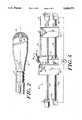
- FIG. 1is a perspective, sectional view of a guide wire assembly constructed in accord with the present invention.
- FIGS. 2is a sectional view of portions of the core wire of the guide wire assembly of FIG. 1.
- FIGS. 3a and 3bare sectional views illustrative of the practice of the present invention.
- FIG. 4shows a system useful for manufacturing the guide wire assembly of FIG. 1 and the device of FIG. 3b.
- FIGS. 1-2illustrate a guide wire, generally designated 10.
- guide wire 10has a tip portion 12 about 2 inches long, a proximal portion 14 about 41/2 feet long, and an distal portion 16 about 10 inches long.
- the maximum diameter of the complete wire assemblyis 0.014 in.; current requirements are that, in field testing, it pass through an 0.014 in. diameter hole.
- the guide wirecomprises a stainless steel core wire 18 that extends axially the length of the device and that, except in some of the tip portion 12, is covered by a plastic (e.g., Teflon) sleeve 20.
- the core wire 18varies in diameter along its length; the overall diameter of the complete guide wire 10 is substantially constant.
- core wire 18has a substantially constant diameter of about 0.00128 in.
- the distal end of proximal portion 14tapers to a diameter of about 0.010 in. before joining the distal portion 16. Adjacent its proximal end the diameter of core wire 18 tapers to about 0.010 in. and then continues at that diameter for about 1/2 inch to provide a reduced diameter section 15 for retaining the proximal end of sleeve 20.
- the core wire 18 within distal portion 16includes a number of axially-spaced portions arranged so that the overall diameter of the core wire decreases, in steps, from a 0.010 in. adjacent proximal portion 14 to about 0.0056 in. at the proximal end of tip portion 12.
- a short, 0.100 in. diameter section at the proximal endincludes a plurality of annular locking grooves 22, having a radial depth of about 0.0010 in.
- the major length of the core wire in distal portion 16has a diameter of about 0.007 inches, and the wire tapers towards the distal end to provide an about 3 inches long, 0.0056 inch diameter length at the proximal end of tip portion 12.
- core wire 18includes an annular ring 24, about 0.0064 inches in diameter and 0.015 in. in axial length.
- the portion of the core wire within tip portiontapers from an initial diameter of about 0.0056 in. (where it joins distal portion 16) to about 0.003 inches at ring 24.
- the core wirecontinues to taper to a diameter of about 0.0022 in.
- the distal end of the core wire, including part of the taperis flattened to a thickness of about 0.0010 in.
- the flat portion 25is secured, typically by gold brazing, to an essentially hemispherical tip 26 (as shown on FIG. 2) at the far distal end of the guide wire.
- Tip portion 12also includes a tapered spring 28 (shown most clearly in FIG. 2) of helically wrapped (about 660 turns) of platinum wire (about 0.0013 in. thick by 0.003 in. wide) that generally coaxially surrounds the length of core wire 18 within the tip portion.
- Spring 28has an outer diameter of about 0.0139 in. at its distal end (where it is gold brazed to tip 26) and tapers to provide a diameter about 0.0104 in. from approximately its mid-point (where it is gold brazed to ring 24) to its proximal end.
- Teflon sleeve 20varies in thickness.
- the sleeveis about 0.0002 to about 0.0004 inches (preferably about 0.0003 inches) thick, so that it adds not more than about 0.0008 (and preferably only about 0.0006) inches to the overall diameter of the core wire 18, and the overall diameter of the guide wire 10 in the proximal portion will not be more than 0.014 (and preferably will not be more than about 0.0134) inches.
- the thickness of sleeve 20increases to a maximum of about 0.002 in., but the outer diameter remains less than 0.014 in.
- the sleeve 20is also of increased thickness; but, again, at all points the thickness is controlled so that the overall diameter of the guide wire 10 will not exceed 0.014 inches.
- the sleeveis about 0.0015 to 0.0020 inches thick, including the portion that fills in the grooves 22 and retains the proximal end of the sleeve 20 in position, thus maintaining an outer overall diameter of guide wire 10 not greater than about 0.014 inches.
- Teflon sleeve 20In the distal portion 16 of guide wire 10, between the proximal end portion including grooves 22 and spring 28 at its distal end, Teflon sleeve 20 varies between about 0.0015 and 0.0030 inches in thickness. It will be recalled that the core wire 18 tapers in diameter from about 0.010, in the region including grooves 22 to about 0.0056 adjacent tip portion 12. The diameter of sleeve 20 is greater adjacent the latter so that, along the entire length of the distal portion 16, the overall diameter of guide wire 10 is more uniform than is the diameter of the core wire 18.
- a sleeve thickness of 0.0030 adjacent tip portion 12provides a total guide wire diameter of about 0.0115, while an 0.0015 sleeve thickness in the region adjacent proximal portion 14 provides a total guide wire diameter (about 0.013 inch) that is still less than the maximum desired diameter of about 0.014 inches.
- the distal end of the sleeve 20extends slightly beyond ring 24 and tightly engages (e.g., is heat shrunk around) the proximal approximately 1 inch portion of tip spring 28. Where spring 28 overlies and is wrapped around ring 24, its overall outer diameter is approximately 0.0105 inches. The portion of sleeve 20 surrounding spring 28 has a radial thickness of about 0.0015 inches, thus providing a maximum diameter in the tip region 12 of a little less than 0.014 inches.
- the entire length of the Teflon sleeve 20is heat shrunk so that the sleeve 20 tightly engages core wire 18 (or, in the tip portion, spring 28) throughout substantially the entire length of the guide wire.
- sleeve 20engages not only the tip and distal portions of the core wire, but proximal portion 14 also. In other embodiments, the sleeve 20 may extend only from the tip portion 12 and to (and over) the grooves 22 at the proximal end of distal portion 16.
- one end of the sleeve 20will tightly engage the annular locking grooves 22, the other end of the sleeve will tightly engage the proximal portion of spring 28, and the rest of the sleeve will be tightly heat-shrunk around the portions of the core wire therebetween.
- FIGS. 3 and 4illustrate the manner in which a Teflon (or other heat shrinkable organic plastic) tube 120 is drawn over and fitted tightly around a rod or wire 118.
- the heat shrinkable tube 120initially has an inside diameter that is considerably larger than the outside diameter of the rod 118 around which it is fitted.
- Small diameter, heat-shrinkable tubeis commercially available from, for example, Zeus Industrial Products of Orangeburg, S.C.
- the tube used in the preferred embodiment, obtained from Zeushas an initial inside diameter of about 0.025 in. It is constructed so that, its recovered size (i.e., the size of the tube after it has been heat shrunk around the smallest diameter cylinder around which it regularly will fit with no intervening gap) is an inside diameter of 0.006 inches and a wall thickness of 0.003 in. ⁇ 0.001 in.
- the volume of the shrunk tubeis, of course, substantially the same as that of the original tube; and that the wall thickness of the shrunk tube thus will vary according to the tube's final inside diameter. If, for example, the tube is shrunk around an 0.010 inch diameter rod, the final inside diameter of the heat shrunk tube will be 0.010 inches (the same as the outside diameter of the shaft) but the wall thickness will be less than that which would be obtained if it were heat shrunk around an 0.006 in. diameter rod.
- the precise shrinkage characteristics of the tubemay vary from production lot to production lot, but have been found to be substantially constant in any single lot.
- heat shrinkable tubehas been applied to medical guide wires simply by slipping the tube over the wire and then applying heat. This produces a device in which the tube tightly surrounds and engages the underlying guide wire, at least those portions having a diameter equal to or greater than the inside diameter of the recovered tube.
- the overall diameter of such a composite tube-wirewill depend only on the size of the tube and wire; and the wall thickness of the shrunk tube is essentially uncontrolled.
- the present inventionis based on the discovery that the wall thickness of the shrunk tube may be reduced, to considerably less than that of the specified "recovered” tube and in a controlled manner, by applying tension to, and thus stretching the heated zone of, the tube relative to the inner core wire as the tube is heat shrunk.
- the wall thickness of the shrunk tubemay be controllably reduced, e.g., to 10% or less of the specified wall thickness of normal "recovered” tube, and it is also possible to obtain different desirable wall thicknesses by varying the amount of stretch.
- FIG. 3billustrates, somewhat schematically, variable wall thicknesses that may be obtained by controllably shrinking tube 120 around rod 118.
- rod 118includes two portions 117a and 117b having outer diameters of about 0.010 inches, and two others, designated 119a and 119b, having reduced diameters of about 0.008 inches.
- tube 120has an inner diameter of about 0.025 inches and an 0.0006 inch thick wall. It will be noted the length of the initial length of tube 120 is considerably less than that of the rod 118 around which it is to be heat shrunk.
- FIG. 3bshows the tube 120 heat shrunk around the rod 118 according to the present invention.
- the sizes of the rod portions 117, 119have, of course, remained the same; and the tube tightly engages the entire outer surface of the rod.
- the different portions of the heat shrunk tube 120have substantially different wall thicknesses.
- the portions of the tube surrounding rod portions 117a and 119awere heat shrunk in the conventional manner, simply by applying heat.
- the resultwas that the tube surrounding portion 117a is about 0.005 in. thick; because portion 119a has a slightly smaller diameter, the tube surrounding it has a wall thickness of about 0.0055 in.
- the overall outer diameters of the tube lengths surrounding rod portions 117a (0.022 in.) and 119a (0.019 in.)vary almost as much as do the diameters of the inner rod portions 117a, 119a themselves; the relatively slight differential in diameter is due only to the considerably smaller diameter of rod portion 119a and the natural shrink characteristics of the tube.
- the lengths of the unshrunk (FIG. 3a) and shrunk tube (FIG. 3b) surrounding portions 117a, 119aare substantially the same.
- the heat-shrunk tube surrounding and engaging portion 117bhas a wall thickness of about 0.0005 inches, and the wall thickness of the shrunk tube surrounding rod portion 119b is about 0.0025 inches.
- the outer diameters of the tube lengths surrounding rod portions 117b and 119bare essentially the same, about 0.013 inches.
- the lengths of tube surrounding portions 117b and 119bwere substantially stretched during the heat shrinking process, e.g., the heat shrunk tube around rod portion 117b in FIG. 3b was drawn form an unshrunk tube portion (FIG.
- this controlled wall thicknessis provided by applying heat to successive annular zones of the tube 120 while simultaneously stretching the heated zone of the tube (each zone surrounds the portion of the rod onto which the heated tube will be shrunk) at a carefully controlled rate.
- FIG. 4illustrates, again some what schematically, a system 96 used for applying a Teflon coating of varying wall thickness to, for example, rod 118 or a core wire 18.
- the systemincludes a heater 100, a support 110 adjacent the heater, a pair of carriages 102 and 104 positioned on opposite sides of the heater 100 and support 110, and a control system 106 for controlling the speeds at which carriages 102, 104 are moved relative to the heater.
- the two carriages 102, 104are mounted on a horizontal guide rod 108, and on a respective one of a pair of coaxial, threaded drives 103, 105.
- Each of drives 103, 105is driven by a respective stepping motor 103a, 105a so that the speeds of rotation of the respective drive, and thus the rate at which each carriage advances, can be independently controlled.
- a length of Teflon tubing 20is slipped over the guide wire 18 around which the tube is to be heat shrunk.
- One end of the tubingis positioned essentially flush with the distal end of the tip portion 18 of the guide wire; and a pair of jaws 118 on carriage 102 engages the leading end, e.g., the distal approximately 1/8 inch of tip portion 12, of core wire 18 and the portion of tubing 20 surrounding it.
- the other, and trailing, end of the tubingis intermediate the length of the core wire and is positioned on the other side of heater 100 and support 110.
- a set of jaws 120 on carriage 104which also is on the other side of heater 100 and support 110, engages the trailing end of tubing 20 but does not engage the core wire 18.
- Heater 100is a conventional hot air shrink wrap heater and includes a hot air blower 99 and a curved air flow director 97 which directs hot air from the blower 99 onto the tubing to be heat shrunk.
- air flow director 97is mounted in a plane generally perpendicular to the axes of core wire 18, sleeve 20 and drives 103, 105, and is arranged so that hot air is directed onto a substantially 360 degree annular portion of tube 20 as carriage 102 draws the core wire 18 and surrounding tube 20 through the heater.
- control system 106controls the speeds at which carriage 102, 104 move relative to heater 100.
- Conventional control circuitry in control system 106permits the speeds of rotation of the stepping motors 103, 105a, and thus the rate of axial movement of the two carriages, to be programmable and accurately controlled.
- carriage 102moves the wire and surrounding tube through the plane of heater 100, thus causing hot air from the heater 100 to heat and shrink successive annular zones of the tube.
- speed at which wire 18 moves through the annular heat zone created by heater 100is the same as the speed at which carriage 102 is advanced by drive 103.
- carriage 102moves at a constant rate, e.g., about 6 inches/minute, thus drawing the core wire through the annular heating zone created by heater director 97 at the same speed.
- Carriage 104mounted on the other side of heater 100 and engaging the proximal end of the tube 20, moves in the same direction as carriage 102 during a heat shrinking operation.
- the speed at which controller 106 advances the carriage 104 towards heater 100is not constant. Rather it varies from a maximum speed that is essentially the same as that of carriage 102 to a minimum speed that is substantially less than, in the preferred embodiment about 1/10th of that of, carriage 102.
- the speed chosen for carriage 104 at any particular time during the heat shrinking operationdepends on the desired wall thickness of the heat-shrunk tubing.
- the maximum wall thicknessis obtained when carriages 102 and 104 move at the same speed.
- carriage 104moves more slowly than carriage 102, the annular zone of the tube 20 that has been heated to its plastic flow temperature in the annular heating zone of hot air deflector 97 is stretched axially, resulting in a heat shrunk tube portion having a thinner wall.
- the extent to which the tube thickness is reducedis directly related to the relative speeds of carriages 102 and 104.
- the thickness of the shrunk tube applied during that part of the procedurewill be almost exactly half that of the thickness resulting when the two carriages are moved at the same speed; similarly, the wall thickness may be reduced by about 90% by advancing carriage 104 at a speed of about 1/10 that of carriage 102. Tube wall thicknesses as small as 0.0001 in., or less, may been obtained.
- coated rodsuch as shown in FIG. 3b may easily be formed using the shorter, and larger initial diameter, tube shown in FIG. 3a.
- the rod 118 and tube 120as shown in FIG. 3a, are mounted in the system with the leading ends of the rod and tube engaged by using 102, and the trailing end of tube 120 engaged by carriage 104.
- Carriage 102is advanced all the way to the right (as viewed in FIG. 4) to adjacent the left side of support 110.
- Carriage 104is positioned to the right of support 110 that the distance between it and carriage 102 is substantially equal to the length of tube 120.
- heater 100is tuned on 102 is moved the left (as viewed in FIG. 4).
- the carriage speedis such that heater will maintain an annular zone of the tubing 120 being drawn past the heater at the desired heat-shrink temperature.
- the rate of movement of carriage 102is substantially constant throughout the entire controlled heat shrink procedure.
- the speed of carriage 104is never greater than that of carriage 102 (so that there will always be at least minimal tension exerted on the tube), but this varies depending on the desired wall thickness of the shrunk tube.
- the carriage 104 supporting the trailing end of tube 120is advanced (again to the left as viewed in FIG.
- the speed of carriage 104is reduced during the period that carriage 102 is drawing rod portion 117b through the annular heating zone, to about 1/4th that of carriage 102, thereby reducing the wall thickness of the tube by about 75%.
- the speed of carriage 104is about 60% that of carriage 102, resulting in a wall thickness (0.0015) that is about 60% that of the tube surrounding rod portion 119a.
- the speed of carriage 104is similarly varied relative to that of carriage 102 when the system 96 of FIG. 4 is used to produce the coated guide wire 10 of FIGS. 1 and 2.
- the coaxial core wire 18 and Teflon sleeve 20are mounted in system 98 so that the wire and coaxial tube extend from one side of heater 100 to the other, generally parallel to the axes of drives 103, 105.
- Jaws 118engage both the leading ends of both the sleeve 20 and the distal end of tip portion 12 of the core wire 18, and jaws 120 engage the trailing end of the sleeve.
- a hook 116 on support 110holds the wire and sleeve in position relative to heater 100.
- the tube 20is heat shrunk around the far distal end of tip portion 12. Movement of carriages 102, 104 begins, with both carriages advancing at the same speed, as soon as the heating end of the tube reaches the required heat shrink temperature. It will be noted that this initial phase shrinks the tube around the spring 28 on the distal side of ring 24. In a later stage of the manufacturing procedure, this portion of the tubing will be removed so that the final product, as shown in FIG. 1, has no sleeve surrounding the far distal portion of the spring.
- carriage 102continues to move, away from heater 100, at a substantially constant (typically about 6 inches per minute) rate.
- Carriage 104also continues to move, in the same direction (towards heater 100), but at a controlled variable rate.
- carriage 102moves at about half the speed of carriage 104, so that the wall thickness of the shrunk sleeve will be reduced to about 0.0015 inches.
- the portions of the core wire 18 in distal portion 16have a diameter-(about 0.007 to 0.0056 in.) that is significantly less than the about 0.0104 inch diameter of spring 28.
- the two carriagesare moved at approximately the same speed while the distal portion 12 is drawn past heater 100, so that the wall thickness of the sleeve shrunk onto the distal portion will (subject always to the limitation that the maximum overall diameter of the finished core wire 10 cannot exceed 0.014 inches) approach the recovered thickness (approximately 0.003 in.) of the sleeve, and will provide a distal portion having an overall diameter that closely approximates that of the rest of the guide wire.
- the outer diameter of the grooves 22 at the distal end of the proximal portion of core wireis, as discussed previously, about 0.010 inches. Accordingly, in this region the maximum permitted sleeve wall thickness (measuring from the outer surface, and not the bottom, of grooves 22) is slightly less than 0.002 inches. To provide this thickness, carriage 104 is slowed, typically to a speed of about two-thirds that of carriage 102 while this portion of the sleeve and core wire are being advanced through the heat zone of heater 100. Similar relative speeds are employed when sleeve is being heat shrunk around the reduced diameter portion 15 at the extreme proximal end of the core wire.
- the core wire 18has an outer diameter of about 0.0128 in. and only a very thin coating can be permitted if the final diameter is to be held below the maximum 0.014 inches.
- carriage 104is slowed to a speed of only about 1/10 that of carriage 102 when the sleeve is being heat shrunk around this portion of the core wire, and the wall thickness of the shrunk sleeve is only about 0.0003 inches, about 10% of the sleeve's normal recovered wall thickness.
Landscapes
- Health & Medical Sciences (AREA)
- Life Sciences & Earth Sciences (AREA)
- Biomedical Technology (AREA)
- Pulmonology (AREA)
- Engineering & Computer Science (AREA)
- Anesthesiology (AREA)
- Biophysics (AREA)
- Heart & Thoracic Surgery (AREA)
- Hematology (AREA)
- Animal Behavior & Ethology (AREA)
- General Health & Medical Sciences (AREA)
- Public Health (AREA)
- Veterinary Medicine (AREA)
- Media Introduction/Drainage Providing Device (AREA)
- Lining Or Joining Of Plastics Or The Like (AREA)
Abstract
Description
Claims (15)
Priority Applications (4)
| Application Number | Priority Date | Filing Date | Title |
|---|---|---|---|
| US08/069,050US5606979A (en) | 1993-05-28 | 1993-05-28 | Guide wire |
| JP7500983AJPH08510675A (en) | 1993-05-28 | 1994-05-27 | Guide wire |
| PCT/US1994/005996WO1994027654A2 (en) | 1993-05-28 | 1994-05-27 | Guide wire |
| EP94919270AEP0700271A4 (en) | 1993-05-28 | 1994-05-27 | Guide wire |
Applications Claiming Priority (1)
| Application Number | Priority Date | Filing Date | Title |
|---|---|---|---|
| US08/069,050US5606979A (en) | 1993-05-28 | 1993-05-28 | Guide wire |
Publications (1)
| Publication Number | Publication Date |
|---|---|
| US5606979Atrue US5606979A (en) | 1997-03-04 |
Family
ID=22086409
Family Applications (1)
| Application Number | Title | Priority Date | Filing Date |
|---|---|---|---|
| US08/069,050Expired - LifetimeUS5606979A (en) | 1993-05-28 | 1993-05-28 | Guide wire |
Country Status (4)
| Country | Link |
|---|---|
| US (1) | US5606979A (en) |
| EP (1) | EP0700271A4 (en) |
| JP (1) | JPH08510675A (en) |
| WO (1) | WO1994027654A2 (en) |
Cited By (40)
| Publication number | Priority date | Publication date | Assignee | Title |
|---|---|---|---|---|
| US5788654A (en)* | 1995-07-18 | 1998-08-04 | Schneider (Europe) A.G. | Wedge-tipped catheter guidewire |
| WO1999025413A1 (en)* | 1997-11-18 | 1999-05-27 | Advanced Cardiovascular Systems, Inc. | Guidewire with shaped intermediate portion |
| WO1999039649A1 (en) | 1998-02-10 | 1999-08-12 | Dubrul William R | Occlusion, anchoring, tensioning and flow direction apparatus and methods for use |
| US6132389A (en)* | 1998-04-23 | 2000-10-17 | Advanced Cardiovascular Systems, Inc. | Proximally tapered guidewire tip coil |
| US6450975B1 (en)* | 1999-12-30 | 2002-09-17 | Advanced Cardiovascular Systems, Inc. | Ultrasonic transmission guide wire |
| US6494891B1 (en)* | 1999-12-30 | 2002-12-17 | Advanced Cardiovascular Systems, Inc. | Ultrasonic angioplasty transmission member |
| WO2002002170A3 (en)* | 2000-06-30 | 2003-01-03 | Micrus Corp | Variable stiffness electrically conductive composite resistive heating catheter shaft |
| DE10138953A1 (en)* | 2001-08-03 | 2003-02-27 | Epflex Feinwerktech Gmbh | Guiding wire for surgical instrument comprises core wire made from super elastic material, screw spring casing surrounding the core wire, and end cap to connect the front end section of the core wire with the front section of the casing |
| US6589253B1 (en) | 1999-12-30 | 2003-07-08 | Advanced Cardiovascular Systems, Inc. | Ultrasonic angioplasty transmission wire |
| US6673025B1 (en) | 1993-12-01 | 2004-01-06 | Advanced Cardiovascular Systems, Inc. | Polymer coated guidewire |
| US20040024348A1 (en)* | 2001-08-24 | 2004-02-05 | Redding Bruce K. | Substance delivery device |
| US20040151882A1 (en)* | 2002-09-26 | 2004-08-05 | Fujitsu Limited | Wiring board with core layer containing inorganic filler |
| US20040167439A1 (en)* | 2003-02-26 | 2004-08-26 | Sharrow James S. | Guidewire having textured proximal portion |
| US20040167440A1 (en)* | 2003-02-26 | 2004-08-26 | Sharrow James S. | Multiple diameter guidewire |
| US20040193146A1 (en)* | 2001-02-15 | 2004-09-30 | Endo Via Medical, Inc. | Robotically controlled surgical instruments |
| US20050054951A1 (en)* | 2003-09-05 | 2005-03-10 | Scimed Life Systems, Inc. | Medical device coil |
| US20050054950A1 (en)* | 2003-09-05 | 2005-03-10 | Scimed Life Systems, Inc. | Medical device coil |
| US20050197597A1 (en)* | 2004-03-05 | 2005-09-08 | Medtronic Vascular, Inc. | Guidewire with hollow distal section |
| US20050216033A1 (en)* | 2001-02-15 | 2005-09-29 | Endo Via Medical Inc. | Robotically controlled medical instrument with a flexible section |
| US20060135979A1 (en)* | 2004-12-16 | 2006-06-22 | Scimed Life Systems, Inc. | Catheter tip to reduce wire lock |
| EP1698370A1 (en)* | 2005-03-02 | 2006-09-06 | Terumo Kabushiki Kaisha | Guide wire |
| US20070239120A1 (en)* | 1998-02-24 | 2007-10-11 | Brock David L | Flexible instrument |
| US20070239106A1 (en)* | 2001-02-15 | 2007-10-11 | Hansen Medical, Inc. | Coaxial catheter system |
| US20070239170A1 (en)* | 1998-02-24 | 2007-10-11 | Brock David L | Flexible instrument |
| US20070250074A1 (en)* | 1998-02-24 | 2007-10-25 | Brock David L | Flexible instrument |
| US20070255217A1 (en)* | 2003-09-16 | 2007-11-01 | Abbott Cardiovascular Systems Inc. | Textured polymer coated guide wire and method of manufacture |
| US7331973B2 (en)* | 2002-09-30 | 2008-02-19 | Avdanced Cardiovascular Systems, Inc. | Guide wire with embolic filtering attachment |
| US20080146967A1 (en)* | 1997-06-04 | 2008-06-19 | Richardson Mark T | Polymer coated guidewire |
| US7455646B2 (en) | 1997-06-04 | 2008-11-25 | Advanced Cardiovascular Systems, Inc. | Polymer coated guide wire |
| US20090209888A1 (en)* | 2008-02-18 | 2009-08-20 | Seyed Hessam Khatami | Spine Wheel |
| US8414598B2 (en) | 1998-02-24 | 2013-04-09 | Hansen Medical, Inc. | Flexible instrument |
| US8414505B1 (en) | 2001-02-15 | 2013-04-09 | Hansen Medical, Inc. | Catheter driver system |
| US9186487B2 (en) | 1997-11-12 | 2015-11-17 | Genesis Technologies Llc | Medical device and method |
| US9498604B2 (en) | 1997-11-12 | 2016-11-22 | Genesis Technologies Llc | Medical device and method |
| US9561094B2 (en) | 2010-07-23 | 2017-02-07 | Nfinium Vascular Technologies, Llc | Devices and methods for treating venous diseases |
| US10953204B2 (en) | 2017-01-09 | 2021-03-23 | Boston Scientific Scimed, Inc. | Guidewire with tactile feel |
| US10967154B2 (en) | 2016-02-22 | 2021-04-06 | Arizona Board Of Regents On Behalf Of Arizona State University | Adjustable guidewire |
| US11266414B2 (en) | 2014-06-04 | 2022-03-08 | Vascular Development Corp, Llc | Low radial force vascular device and method of occlusion |
| US11452533B2 (en) | 2019-01-10 | 2022-09-27 | Abbott Cardiovascular Systems Inc. | Guide wire tip having roughened surface |
| US12440650B2 (en) | 2023-02-27 | 2025-10-14 | Vascular Development Corp, Llc | Augmented delivery catheter and method |
Families Citing this family (1)
| Publication number | Priority date | Publication date | Assignee | Title |
|---|---|---|---|---|
| US6012213A (en)* | 1995-06-07 | 2000-01-11 | Chang; Joseph J. | Method for forming a rib on a cannula for a tip protection device |
Citations (9)
| Publication number | Priority date | Publication date | Assignee | Title |
|---|---|---|---|---|
| US3841308A (en)* | 1973-10-15 | 1974-10-15 | Medical Evaluation Devices & I | Distally valved catheter device |
| US3973556A (en)* | 1975-06-20 | 1976-08-10 | Lake Region Manufacturing Company, Inc. | Smoothened coil spring wire guide |
| US4080706A (en)* | 1975-04-22 | 1978-03-28 | Medrad, Inc. | Method of manufacturing catheter guidewire |
| US4884579A (en)* | 1988-04-18 | 1989-12-05 | Target Therapeutics | Catheter guide wire |
| US4917104A (en)* | 1988-06-10 | 1990-04-17 | Telectronics Pacing Systems, Inc. | Electrically insulated "J" stiffener wire |
| US4955862A (en)* | 1989-05-22 | 1990-09-11 | Target Therapeutics, Inc. | Catheter and catheter/guide wire device |
| US5129890A (en)* | 1989-06-29 | 1992-07-14 | Cook Incorporated | Hydrophilically coated flexible wire guide |
| US5171383A (en)* | 1987-01-07 | 1992-12-15 | Terumo Kabushiki Kaisha | Method of manufacturing a differentially heat treated catheter guide wire |
| US5267574A (en)* | 1992-09-10 | 1993-12-07 | Cordis Corporation | Guidewire with spring and a heat shrinkable connection |
Family Cites Families (2)
| Publication number | Priority date | Publication date | Assignee | Title |
|---|---|---|---|---|
| US4737380A (en)* | 1987-01-09 | 1988-04-12 | Monaghan Medical Corporation | Electrode with stretched heat-shrinkable outer insulator |
| CA2068584C (en)* | 1991-06-18 | 1997-04-22 | Paul H. Burmeister | Intravascular guide wire and method for manufacture thereof |
- 1993
- 1993-05-28USUS08/069,050patent/US5606979A/ennot_activeExpired - Lifetime
- 1994
- 1994-05-27JPJP7500983Apatent/JPH08510675A/enactivePending
- 1994-05-27EPEP94919270Apatent/EP0700271A4/ennot_activeWithdrawn
- 1994-05-27WOPCT/US1994/005996patent/WO1994027654A2/ennot_activeApplication Discontinuation
Patent Citations (9)
| Publication number | Priority date | Publication date | Assignee | Title |
|---|---|---|---|---|
| US3841308A (en)* | 1973-10-15 | 1974-10-15 | Medical Evaluation Devices & I | Distally valved catheter device |
| US4080706A (en)* | 1975-04-22 | 1978-03-28 | Medrad, Inc. | Method of manufacturing catheter guidewire |
| US3973556A (en)* | 1975-06-20 | 1976-08-10 | Lake Region Manufacturing Company, Inc. | Smoothened coil spring wire guide |
| US5171383A (en)* | 1987-01-07 | 1992-12-15 | Terumo Kabushiki Kaisha | Method of manufacturing a differentially heat treated catheter guide wire |
| US4884579A (en)* | 1988-04-18 | 1989-12-05 | Target Therapeutics | Catheter guide wire |
| US4917104A (en)* | 1988-06-10 | 1990-04-17 | Telectronics Pacing Systems, Inc. | Electrically insulated "J" stiffener wire |
| US4955862A (en)* | 1989-05-22 | 1990-09-11 | Target Therapeutics, Inc. | Catheter and catheter/guide wire device |
| US5129890A (en)* | 1989-06-29 | 1992-07-14 | Cook Incorporated | Hydrophilically coated flexible wire guide |
| US5267574A (en)* | 1992-09-10 | 1993-12-07 | Cordis Corporation | Guidewire with spring and a heat shrinkable connection |
Cited By (80)
| Publication number | Priority date | Publication date | Assignee | Title |
|---|---|---|---|---|
| US6673025B1 (en) | 1993-12-01 | 2004-01-06 | Advanced Cardiovascular Systems, Inc. | Polymer coated guidewire |
| US5788654A (en)* | 1995-07-18 | 1998-08-04 | Schneider (Europe) A.G. | Wedge-tipped catheter guidewire |
| US7455646B2 (en) | 1997-06-04 | 2008-11-25 | Advanced Cardiovascular Systems, Inc. | Polymer coated guide wire |
| US20080146967A1 (en)* | 1997-06-04 | 2008-06-19 | Richardson Mark T | Polymer coated guidewire |
| US7494474B2 (en) | 1997-06-04 | 2009-02-24 | Advanced Cardiovascular Systems, Inc. | Polymer coated guidewire |
| US9498604B2 (en) | 1997-11-12 | 2016-11-22 | Genesis Technologies Llc | Medical device and method |
| US9186487B2 (en) | 1997-11-12 | 2015-11-17 | Genesis Technologies Llc | Medical device and method |
| US6296616B1 (en) | 1997-11-18 | 2001-10-02 | Advanced Cardiovascular Systems, Inc. | Guidewire with shaped intermediate portion |
| WO1999025413A1 (en)* | 1997-11-18 | 1999-05-27 | Advanced Cardiovascular Systems, Inc. | Guidewire with shaped intermediate portion |
| US6106485A (en)* | 1997-11-18 | 2000-08-22 | Advanced Cardivascular Systems, Inc. | Guidewire with shaped intermediate portion |
| US6562021B1 (en) | 1997-12-22 | 2003-05-13 | Micrus Corporation | Variable stiffness electrically conductive composite, resistive heating catheter shaft |
| WO1999039649A1 (en) | 1998-02-10 | 1999-08-12 | Dubrul William R | Occlusion, anchoring, tensioning and flow direction apparatus and methods for use |
| US7713190B2 (en) | 1998-02-24 | 2010-05-11 | Hansen Medical, Inc. | Flexible instrument |
| US7905828B2 (en) | 1998-02-24 | 2011-03-15 | Hansen Medical, Inc. | Flexible instrument |
| US8414598B2 (en) | 1998-02-24 | 2013-04-09 | Hansen Medical, Inc. | Flexible instrument |
| US8114097B2 (en) | 1998-02-24 | 2012-02-14 | Hansen Medical, Inc. | Flexible instrument |
| US20070250073A1 (en)* | 1998-02-24 | 2007-10-25 | Brock David L | Flexible instrument |
| US20070250074A1 (en)* | 1998-02-24 | 2007-10-25 | Brock David L | Flexible instrument |
| US20070255291A1 (en)* | 1998-02-24 | 2007-11-01 | Brock David L | Flexible instrument |
| US7371210B2 (en) | 1998-02-24 | 2008-05-13 | Hansen Medical, Inc. | Flexible instrument |
| US7867241B2 (en) | 1998-02-24 | 2011-01-11 | Hansen Medical, Inc. | Flexible instrument |
| US7775972B2 (en) | 1998-02-24 | 2010-08-17 | Hansen Medical, Inc. | Flexible instrument |
| US7931586B2 (en) | 1998-02-24 | 2011-04-26 | Hansen Medical, Inc. | Flexible instrument |
| US20070239170A1 (en)* | 1998-02-24 | 2007-10-11 | Brock David L | Flexible instrument |
| US7918861B2 (en) | 1998-02-24 | 2011-04-05 | Hansen Medical, Inc. | Flexible instrument |
| US20070260115A1 (en)* | 1998-02-24 | 2007-11-08 | Brock David L | Flexible instrument |
| US20070239120A1 (en)* | 1998-02-24 | 2007-10-11 | Brock David L | Flexible instrument |
| US6132389A (en)* | 1998-04-23 | 2000-10-17 | Advanced Cardiovascular Systems, Inc. | Proximally tapered guidewire tip coil |
| US6589253B1 (en) | 1999-12-30 | 2003-07-08 | Advanced Cardiovascular Systems, Inc. | Ultrasonic angioplasty transmission wire |
| US6450975B1 (en)* | 1999-12-30 | 2002-09-17 | Advanced Cardiovascular Systems, Inc. | Ultrasonic transmission guide wire |
| US6494891B1 (en)* | 1999-12-30 | 2002-12-17 | Advanced Cardiovascular Systems, Inc. | Ultrasonic angioplasty transmission member |
| WO2002002170A3 (en)* | 2000-06-30 | 2003-01-03 | Micrus Corp | Variable stiffness electrically conductive composite resistive heating catheter shaft |
| US7955316B2 (en) | 2001-02-15 | 2011-06-07 | Han Sen Medical, Inc. | Coaxial catheter system |
| US8603068B2 (en) | 2001-02-15 | 2013-12-10 | Hansen Medical Inc. | Coaxial catheter system |
| US20070239105A1 (en)* | 2001-02-15 | 2007-10-11 | Hansen Medical, Inc. | Coaxial catheter system |
| US10695536B2 (en) | 2001-02-15 | 2020-06-30 | Auris Health, Inc. | Catheter driver system |
| US20070239106A1 (en)* | 2001-02-15 | 2007-10-11 | Hansen Medical, Inc. | Coaxial catheter system |
| US20080119824A1 (en)* | 2001-02-15 | 2008-05-22 | Hansen Medical, Inc. | Coaxial catheter system |
| US8414505B1 (en) | 2001-02-15 | 2013-04-09 | Hansen Medical, Inc. | Catheter driver system |
| US20080177284A1 (en)* | 2001-02-15 | 2008-07-24 | Hansen Medical, Inc. | Robotically controlled medical instrument |
| US8187229B2 (en) | 2001-02-15 | 2012-05-29 | Hansen Medical, Inc. | Coaxial catheter system |
| US20110144656A1 (en)* | 2001-02-15 | 2011-06-16 | Hansen Medical, Inc. | Robotically controlled medical instrument |
| US20040193146A1 (en)* | 2001-02-15 | 2004-09-30 | Endo Via Medical, Inc. | Robotically controlled surgical instruments |
| US7854738B2 (en) | 2001-02-15 | 2010-12-21 | Hansen Medical, Inc. | Robotically controlled medical instrument |
| US7608083B2 (en) | 2001-02-15 | 2009-10-27 | Hansen Medical, Inc. | Robotically controlled medical instrument with a flexible section |
| US7699835B2 (en) | 2001-02-15 | 2010-04-20 | Hansen Medical, Inc. | Robotically controlled surgical instruments |
| US20050216033A1 (en)* | 2001-02-15 | 2005-09-29 | Endo Via Medical Inc. | Robotically controlled medical instrument with a flexible section |
| US7727185B2 (en) | 2001-02-15 | 2010-06-01 | Hansen Medical, Inc. | Coaxial catheter system |
| US7744608B2 (en) | 2001-02-15 | 2010-06-29 | Hansen Medical, Inc. | Robotically controlled medical instrument |
| US7819884B2 (en) | 2001-02-15 | 2010-10-26 | Hansen Medical, Inc. | Robotically controlled medical instrument |
| US7766894B2 (en) | 2001-02-15 | 2010-08-03 | Hansen Medical, Inc. | Coaxial catheter system |
| DE10138953A1 (en)* | 2001-08-03 | 2003-02-27 | Epflex Feinwerktech Gmbh | Guiding wire for surgical instrument comprises core wire made from super elastic material, screw spring casing surrounding the core wire, and end cap to connect the front end section of the core wire with the front section of the casing |
| DE10138953B4 (en)* | 2001-08-03 | 2005-03-24 | Epflex Feinwerktechnik Gmbh | Guidewire with core wire and coil spring sheath |
| US20040024348A1 (en)* | 2001-08-24 | 2004-02-05 | Redding Bruce K. | Substance delivery device |
| US20040151882A1 (en)* | 2002-09-26 | 2004-08-05 | Fujitsu Limited | Wiring board with core layer containing inorganic filler |
| US7331973B2 (en)* | 2002-09-30 | 2008-02-19 | Avdanced Cardiovascular Systems, Inc. | Guide wire with embolic filtering attachment |
| US20040167440A1 (en)* | 2003-02-26 | 2004-08-26 | Sharrow James S. | Multiple diameter guidewire |
| US20040167439A1 (en)* | 2003-02-26 | 2004-08-26 | Sharrow James S. | Guidewire having textured proximal portion |
| US8167821B2 (en) | 2003-02-26 | 2012-05-01 | Boston Scientific Scimed, Inc. | Multiple diameter guidewire |
| US20050054950A1 (en)* | 2003-09-05 | 2005-03-10 | Scimed Life Systems, Inc. | Medical device coil |
| US7540845B2 (en) | 2003-09-05 | 2009-06-02 | Boston Scientific Scimed, Inc | Medical device coil |
| US20050054951A1 (en)* | 2003-09-05 | 2005-03-10 | Scimed Life Systems, Inc. | Medical device coil |
| US7833175B2 (en) | 2003-09-05 | 2010-11-16 | Boston Scientific Scimed, Inc. | Medical device coil |
| US20070255217A1 (en)* | 2003-09-16 | 2007-11-01 | Abbott Cardiovascular Systems Inc. | Textured polymer coated guide wire and method of manufacture |
| US8613712B1 (en) | 2003-09-16 | 2013-12-24 | Abbott Cardiovascular Systems Inc. | Textured polymer coated guide wire and method of manufacture |
| US20050197597A1 (en)* | 2004-03-05 | 2005-09-08 | Medtronic Vascular, Inc. | Guidewire with hollow distal section |
| US20060135979A1 (en)* | 2004-12-16 | 2006-06-22 | Scimed Life Systems, Inc. | Catheter tip to reduce wire lock |
| US7744574B2 (en) | 2004-12-16 | 2010-06-29 | Boston Scientific Scimed, Inc. | Catheter tip to reduce wire lock |
| US20060241419A1 (en)* | 2005-03-02 | 2006-10-26 | Terumo Kabushiki Kaisha | Guide wire |
| EP1698370A1 (en)* | 2005-03-02 | 2006-09-06 | Terumo Kabushiki Kaisha | Guide wire |
| US20090209888A1 (en)* | 2008-02-18 | 2009-08-20 | Seyed Hessam Khatami | Spine Wheel |
| US9561094B2 (en) | 2010-07-23 | 2017-02-07 | Nfinium Vascular Technologies, Llc | Devices and methods for treating venous diseases |
| US11266414B2 (en) | 2014-06-04 | 2022-03-08 | Vascular Development Corp, Llc | Low radial force vascular device and method of occlusion |
| US12357314B2 (en) | 2014-06-04 | 2025-07-15 | Vascular Development Corp, Llc | Low radial force vascular device and method of occlusion |
| US10967154B2 (en) | 2016-02-22 | 2021-04-06 | Arizona Board Of Regents On Behalf Of Arizona State University | Adjustable guidewire |
| US11701496B2 (en) | 2016-02-22 | 2023-07-18 | Arizona Board Of Regents On Behalf Of Arizona State University | Adjustable guidewire |
| US10953204B2 (en) | 2017-01-09 | 2021-03-23 | Boston Scientific Scimed, Inc. | Guidewire with tactile feel |
| US11452533B2 (en) | 2019-01-10 | 2022-09-27 | Abbott Cardiovascular Systems Inc. | Guide wire tip having roughened surface |
| US12137923B2 (en) | 2019-01-10 | 2024-11-12 | Abbott Cardiovascular Systems Inc. | Guide wire tip having roughened surface |
| US12440650B2 (en) | 2023-02-27 | 2025-10-14 | Vascular Development Corp, Llc | Augmented delivery catheter and method |
Also Published As
| Publication number | Publication date |
|---|---|
| EP0700271A1 (en) | 1996-03-13 |
| WO1994027654A3 (en) | 1995-02-02 |
| EP0700271A4 (en) | 1997-06-18 |
| JPH08510675A (en) | 1996-11-12 |
| WO1994027654A2 (en) | 1994-12-08 |
Similar Documents
| Publication | Publication Date | Title |
|---|---|---|
| US5606979A (en) | Guide wire | |
| US4516972A (en) | Guiding catheter and method of manufacture | |
| US5335410A (en) | Method of making ultra small diameter catheters and of reinforced tubular product | |
| CA1333464C (en) | Dilatation balloon | |
| US5792401A (en) | Method for making a tubular product | |
| US4764324A (en) | Method of making a catheter | |
| US5722395A (en) | Ultra thin walled wire reinforced endotracheal tubing | |
| US6733819B2 (en) | Method and apparatus for polymer application to intracorporeal device | |
| US20050131387A1 (en) | Catheter having fibrous reinforcement and method of making the same | |
| CA2117088A1 (en) | Flexible tubular device for use in medical applications | |
| JPH06511162A (en) | Catheters with irregular inner and/or outer surfaces to reduce friction during movement | |
| US20210236767A1 (en) | Filament wrapping and reflow system and methods to manufacture an elongate medical device | |
| US5972143A (en) | Angiographic catheter with unitary body and tip sections and method for making same from a continuous feedstock | |
| WO2002011961A1 (en) | Apparatus and method for manufacturing fiber gratings | |
| US4134958A (en) | Method of manufacturing corrugated tubing of polytetrafluorethylene | |
| US3932254A (en) | Apparatus for semi-continuous production of lengthy helical wave guides | |
| US6371929B1 (en) | Method and apparatus for producing steerable coated guidewires and the steerable guidewires produced thereby | |
| CA2222111A1 (en) | Process and apparatus for continuously forming rings of thermoplastic, shrinkable tubular casings | |
| JPH02230108A (en) | Making of flexible tube having rigidity circumferentially for optical fiber cable | |
| US5195991A (en) | Prestressed column | |
| JPH04229911A (en) | Stranded wire manufacturing equipment and manufacturing method | |
| JPS6242833A (en) | Manufacture of wire-imbedded flexible pipe and wire feeding device therefor | |
| CA1186582A (en) | Cardiovascular catheter and method of manufacture | |
| EP0288282A1 (en) | A method of and apparatus for convoluting a tube | |
| JPH0532335B2 (en) |
Legal Events
| Date | Code | Title | Description |
|---|---|---|---|
| STPP | Information on status: patent application and granting procedure in general | Free format text:APPLICATION UNDERGOING PREEXAM PROCESSING | |
| AS | Assignment | Owner name:MICROSPRING COMPANY INC., THE, MASSACHUSETTS Free format text:ASSIGNMENT OF ASSIGNORS INTEREST;ASSIGNOR:HODGSON, WILLIAM S.;REEL/FRAME:006673/0702 Effective date:19930823 | |
| AS | Assignment | Owner name:DEUTSCHE BANK AG, NEW YORK BRANCH, NEW YORK Free format text:SECURITY INTEREST;ASSIGNOR:MICROSPRING COMPANY, LLC, THE;REEL/FRAME:009893/0097 Effective date:19990329 | |
| FPAY | Fee payment | Year of fee payment:4 | |
| AS | Assignment | Owner name:MICROSPRING COMPANY, INC., MINNESOTA Free format text:RELEASE OF SECURITY INTEREST;ASSIGNOR:DEUTSCHE BANK AG;REEL/FRAME:013101/0318 Effective date:20020402 | |
| AS | Assignment | Owner name:WACHOVIA BANK, NATIONAL ASSOCIATION, AS ADMINISTRA Free format text:NOTICE OF GRANT OF SECURITY INTEREST;ASSIGNOR:MICROSPRING COMPANY, LLC, THE;REEL/FRAME:013101/0120 Effective date:20020402 | |
| AS | Assignment | Owner name:MICROSPRING COMPANY, LLC, THE, MASSACHUSETTS Free format text:ASSIGNMENT OF ASSIGNORS INTEREST;ASSIGNOR:MICROSPRING CO., INC., THE;REEL/FRAME:013146/0599 Effective date:19990329 | |
| AS | Assignment | Owner name:MICROSPRING COMPANY, LLC, THE, MINNESOTA Free format text:RELEASE OF SECURITY INTEREST;ASSIGNOR:DEUTSCHE BANK AG, AS COLLATERAL AGENT;REEL/FRAME:013429/0774 Effective date:20020911 | |
| REFU | Refund | Free format text:REFUND - SURCHARGE FOR LATE PAYMENT, SMALL ENTITY (ORIGINAL EVENT CODE: R2554); ENTITY STATUS OF PATENT OWNER: LARGE ENTITY | |
| AS | Assignment | Owner name:CREDIT SUISSE FIRST BOSTON, ACTING THROUGH ITS CAY Free format text:SECURITY AGREEMENT;ASSIGNOR:MICROSPRING COMPANY, LLC, THE;REEL/FRAME:015056/0574 Effective date:20040630 | |
| FPAY | Fee payment | Year of fee payment:8 | |
| AS | Assignment | Owner name:MEDSOURCE TECHNOLOGIES, LLC, MINNESOTA Free format text:ASSIGNMENT OF ASSIGNORS INTEREST;ASSIGNOR:THE MICROSPRING COMPANY;REEL/FRAME:015711/0355 Effective date:20050221 | |
| AS | Assignment | Owner name:ACCELLENT CORP., MASSACHUSETTS Free format text:RELEASE OF PATENT SECURITY AGREEMENT;ASSIGNOR:CREDIT SUISSE, CAYMAN ISLANDS BRANCH, (FORMERLY KNOWN AS CREDIT SUISSE FIRST BOSTON, ACTING THROUGH ITS CAYMAN ISLANDS BRANCH) AS COLLATERAL AGENT;REEL/FRAME:017125/0505 Effective date:20051122 Owner name:MEDICAL DEVICE MANUFACTURING, INC., MASSACHUSETTS Free format text:RELEASE OF PATENT SECURITY AGREEMENT;ASSIGNOR:CREDIT SUISSE, CAYMAN ISLANDS BRANCH, (FORMERLY KNOWN AS CREDIT SUISSE FIRST BOSTON, ACTING THROUGH ITS CAYMAN ISLANDS BRANCH) AS COLLATERAL AGENT;REEL/FRAME:017125/0505 Effective date:20051122 Owner name:UTI CORPORATION, MASSACHUSETTS Free format text:RELEASE OF PATENT SECURITY AGREEMENT;ASSIGNOR:CREDIT SUISSE, CAYMAN ISLANDS BRANCH, (FORMERLY KNOWN AS CREDIT SUISSE FIRST BOSTON, ACTING THROUGH ITS CAYMAN ISLANDS BRANCH) AS COLLATERAL AGENT;REEL/FRAME:017125/0505 Effective date:20051122 Owner name:MEDSOURCE TRENTON, INC., MASSACHUSETTS Free format text:RELEASE OF PATENT SECURITY AGREEMENT;ASSIGNOR:CREDIT SUISSE, CAYMAN ISLANDS BRANCH, (FORMERLY KNOWN AS CREDIT SUISSE FIRST BOSTON, ACTING THROUGH ITS CAYMAN ISLANDS BRANCH) AS COLLATERAL AGENT;REEL/FRAME:017125/0505 Effective date:20051122 Owner name:SPECTRUM MANUFACTURING, INC., MASSACHUSETTS Free format text:RELEASE OF PATENT SECURITY AGREEMENT;ASSIGNOR:CREDIT SUISSE, CAYMAN ISLANDS BRANCH, (FORMERLY KNOWN AS CREDIT SUISSE FIRST BOSTON, ACTING THROUGH ITS CAYMAN ISLANDS BRANCH) AS COLLATERAL AGENT;REEL/FRAME:017125/0505 Effective date:20051122 Owner name:NOBLE-MET, LTD., MASSACHUSETTS Free format text:RELEASE OF PATENT SECURITY AGREEMENT;ASSIGNOR:CREDIT SUISSE, CAYMAN ISLANDS BRANCH, (FORMERLY KNOWN AS CREDIT SUISSE FIRST BOSTON, ACTING THROUGH ITS CAYMAN ISLANDS BRANCH) AS COLLATERAL AGENT;REEL/FRAME:017125/0505 Effective date:20051122 Owner name:CYCAM, INC., MASSACHUSETTS Free format text:RELEASE OF PATENT SECURITY AGREEMENT;ASSIGNOR:CREDIT SUISSE, CAYMAN ISLANDS BRANCH, (FORMERLY KNOWN AS CREDIT SUISSE FIRST BOSTON, ACTING THROUGH ITS CAYMAN ISLANDS BRANCH) AS COLLATERAL AGENT;REEL/FRAME:017125/0505 Effective date:20051122 Owner name:MEDSOURCE TECHNOLOGIES, INC., MASSACHUSETTS Free format text:RELEASE OF PATENT SECURITY AGREEMENT;ASSIGNOR:CREDIT SUISSE, CAYMAN ISLANDS BRANCH, (FORMERLY KNOWN AS CREDIT SUISSE FIRST BOSTON, ACTING THROUGH ITS CAYMAN ISLANDS BRANCH) AS COLLATERAL AGENT;REEL/FRAME:017125/0505 Effective date:20051122 | |
| AS | Assignment | Owner name:JPMORGAN CHASE BANK N.A., AS ADMINISTRATIVE AGENT, Free format text:GRANT OF SECURITY INTEREST IN PATENTS;ASSIGNOR:MEDSOURCE TECHNOLOGIES, LLC;REEL/FRAME:017136/0215 Effective date:20051122 | |
| FEPP | Fee payment procedure | Free format text:PAYOR NUMBER ASSIGNED (ORIGINAL EVENT CODE: ASPN); ENTITY STATUS OF PATENT OWNER: LARGE ENTITY | |
| FPAY | Fee payment | Year of fee payment:12 | |
| REMI | Maintenance fee reminder mailed | ||
| AS | Assignment | Owner name:WELLS FARGO CAPITAL FINANCE, LLC, AS COLLATERAL AG Free format text:GRANT OF SECURITY INTEREST IN PATENT RIGHTS;ASSIGNORS:ACCELLENT INC.;ACCELLENT LLC;AMERICAN TECHNICAL MOLDING, INC.;AND OTHERS;REEL/FRAME:023870/0105 Effective date:20100129 | |
| AS | Assignment | Owner name:ACCELLENT INC.,MASSACHUSETTS Free format text:TERMINATION AND RELEASE OF SECURITY INTEREST IN PATENT RIGHTS;ASSIGNOR:JPMORGAN CHASE BANK, N.A., AS ADMINISTRATIVE AGENT;REEL/FRAME:023928/0409 Effective date:20100129 Owner name:UTI CORPORATION (NOW UTI HOLDINGS, LLC),PENNSYLVAN Free format text:TERMINATION AND RELEASE OF SECURITY INTEREST IN PATENT RIGHTS;ASSIGNOR:JPMORGAN CHASE BANK, N.A., AS ADMINISTRATIVE AGENT;REEL/FRAME:023928/0409 Effective date:20100129 Owner name:MEDSOURCE TECHNOLOGIES, LLC,NEW YORK Free format text:TERMINATION AND RELEASE OF SECURITY INTEREST IN PATENT RIGHTS;ASSIGNOR:JPMORGAN CHASE BANK, N.A., AS ADMINISTRATIVE AGENT;REEL/FRAME:023928/0409 Effective date:20100129 Owner name:MEDSOURCE TRENTON, INC. (NOW MEDSOURCE TRENTON LLC Free format text:TERMINATION AND RELEASE OF SECURITY INTEREST IN PATENT RIGHTS;ASSIGNOR:JPMORGAN CHASE BANK, N.A., AS ADMINISTRATIVE AGENT;REEL/FRAME:023928/0409 Effective date:20100129 Owner name:MEDSOURCE TECHNOLOGIES PITTSBURGH, INC.,PENNSYLVAN Free format text:TERMINATION AND RELEASE OF SECURITY INTEREST IN PATENT RIGHTS;ASSIGNOR:JPMORGAN CHASE BANK, N.A., AS ADMINISTRATIVE AGENT;REEL/FRAME:023928/0409 Effective date:20100129 Owner name:MEDSOURCE TECHNOLOGIES, NEWTON INC.,MASSACHUSETTS Free format text:TERMINATION AND RELEASE OF SECURITY INTEREST IN PATENT RIGHTS;ASSIGNOR:JPMORGAN CHASE BANK, N.A., AS ADMINISTRATIVE AGENT;REEL/FRAME:023928/0409 Effective date:20100129 Owner name:THERMAT ACQUISITION CORP. (NOW THERMAT ACQUISITION Free format text:TERMINATION AND RELEASE OF SECURITY INTEREST IN PATENT RIGHTS;ASSIGNOR:JPMORGAN CHASE BANK, N.A., AS ADMINISTRATIVE AGENT;REEL/FRAME:023928/0409 Effective date:20100129 Owner name:NOBLE-MET, LTD. (NOW NOBLE-MET LLC),VIRGINIA Free format text:TERMINATION AND RELEASE OF SECURITY INTEREST IN PATENT RIGHTS;ASSIGNOR:JPMORGAN CHASE BANK, N.A., AS ADMINISTRATIVE AGENT;REEL/FRAME:023928/0409 Effective date:20100129 Owner name:SPECTRUM MANUFACTURING, INC.,ILLINOIS Free format text:TERMINATION AND RELEASE OF SECURITY INTEREST IN PATENT RIGHTS;ASSIGNOR:JPMORGAN CHASE BANK, N.A., AS ADMINISTRATIVE AGENT;REEL/FRAME:023928/0409 Effective date:20100129 Owner name:PORTLYN, LLC,NEW HAMPSHIRE Free format text:TERMINATION AND RELEASE OF SECURITY INTEREST IN PATENT RIGHTS;ASSIGNOR:JPMORGAN CHASE BANK, N.A., AS ADMINISTRATIVE AGENT;REEL/FRAME:023928/0409 Effective date:20100129 Owner name:DANFORTH BIOMEDICAL, INC. (NOW MEDSOURCE TECHNOLOG Free format text:TERMINATION AND RELEASE OF SECURITY INTEREST IN PATENT RIGHTS;ASSIGNOR:JPMORGAN CHASE BANK, N.A., AS ADMINISTRATIVE AGENT;REEL/FRAME:023928/0409 Effective date:20100129 Owner name:ACT MEDICAL, INC. (NOW MEDSOURCE TECHNOLOGIES, NEW Free format text:TERMINATION AND RELEASE OF SECURITY INTEREST IN PATENT RIGHTS;ASSIGNOR:JPMORGAN CHASE BANK, N.A., AS ADMINISTRATIVE AGENT;REEL/FRAME:023928/0409 Effective date:20100129 Owner name:CYCAM, INC. (NOW MEDSOURCE TECHNOLOGIES PITTSBURGH Free format text:TERMINATION AND RELEASE OF SECURITY INTEREST IN PATENT RIGHTS;ASSIGNOR:JPMORGAN CHASE BANK, N.A., AS ADMINISTRATIVE AGENT;REEL/FRAME:023928/0409 Effective date:20100129 Owner name:G&D, INC. D/B/A STAR GUIDE CORPORATION (NOW G&D, L Free format text:TERMINATION AND RELEASE OF SECURITY INTEREST IN PATENT RIGHTS;ASSIGNOR:JPMORGAN CHASE BANK, N.A., AS ADMINISTRATIVE AGENT;REEL/FRAME:023928/0409 Effective date:20100129 Owner name:THE BANK OF NEW YORK MELLON, AS NOTES COLLATERAL A Free format text:SECURITY AGREEMENT;ASSIGNORS:ACCELLENT INC.;ACCELLENT LLC;BRIMFIELD ACQUISITION, LLC;AND OTHERS;REEL/FRAME:023928/0439 Effective date:20100129 Owner name:ACCELLENT INC., MASSACHUSETTS Free format text:TERMINATION AND RELEASE OF SECURITY INTEREST IN PATENT RIGHTS;ASSIGNOR:JPMORGAN CHASE BANK, N.A., AS ADMINISTRATIVE AGENT;REEL/FRAME:023928/0409 Effective date:20100129 Owner name:UTI CORPORATION (NOW UTI HOLDINGS, LLC), PENNSYLVA Free format text:TERMINATION AND RELEASE OF SECURITY INTEREST IN PATENT RIGHTS;ASSIGNOR:JPMORGAN CHASE BANK, N.A., AS ADMINISTRATIVE AGENT;REEL/FRAME:023928/0409 Effective date:20100129 Owner name:MEDSOURCE TECHNOLOGIES, LLC, NEW YORK Free format text:TERMINATION AND RELEASE OF SECURITY INTEREST IN PATENT RIGHTS;ASSIGNOR:JPMORGAN CHASE BANK, N.A., AS ADMINISTRATIVE AGENT;REEL/FRAME:023928/0409 Effective date:20100129 Owner name:MEDSOURCE TECHNOLOGIES PITTSBURGH, INC., PENNSYLVA Free format text:TERMINATION AND RELEASE OF SECURITY INTEREST IN PATENT RIGHTS;ASSIGNOR:JPMORGAN CHASE BANK, N.A., AS ADMINISTRATIVE AGENT;REEL/FRAME:023928/0409 Effective date:20100129 Owner name:MEDSOURCE TECHNOLOGIES, NEWTON INC., MASSACHUSETTS Free format text:TERMINATION AND RELEASE OF SECURITY INTEREST IN PATENT RIGHTS;ASSIGNOR:JPMORGAN CHASE BANK, N.A., AS ADMINISTRATIVE AGENT;REEL/FRAME:023928/0409 Effective date:20100129 Owner name:NOBLE-MET, LTD. (NOW NOBLE-MET LLC), VIRGINIA Free format text:TERMINATION AND RELEASE OF SECURITY INTEREST IN PATENT RIGHTS;ASSIGNOR:JPMORGAN CHASE BANK, N.A., AS ADMINISTRATIVE AGENT;REEL/FRAME:023928/0409 Effective date:20100129 Owner name:SPECTRUM MANUFACTURING, INC., ILLINOIS Free format text:TERMINATION AND RELEASE OF SECURITY INTEREST IN PATENT RIGHTS;ASSIGNOR:JPMORGAN CHASE BANK, N.A., AS ADMINISTRATIVE AGENT;REEL/FRAME:023928/0409 Effective date:20100129 Owner name:PORTLYN, LLC, NEW HAMPSHIRE Free format text:TERMINATION AND RELEASE OF SECURITY INTEREST IN PATENT RIGHTS;ASSIGNOR:JPMORGAN CHASE BANK, N.A., AS ADMINISTRATIVE AGENT;REEL/FRAME:023928/0409 Effective date:20100129 | |
| AS | Assignment | Owner name:UBS AG, STAMFORD BRANCH, AS THE COLLATERAL AGENT, Free format text:SECURITY INTEREST;ASSIGNORS:ACCELLENT INC.;MEDSOURCE TECHNOLOGIES, NEWTON INC.;MEDSOURCE TECHNOLOGIES, LLC;AND OTHERS;REEL/FRAME:032443/0341 Effective date:20140312 Owner name:GOLDMAN SACHS BANK USA, NEW YORK Free format text:SECURITY INTEREST;ASSIGNORS:ACCELLENT INC.;MEDSOURCE TECHNOLOGIES, NEWTON INC.;MEDSOURCE TECHNOLOGIES, LLC;AND OTHERS;REEL/FRAME:032446/0349 Effective date:20140312 | |
| AS | Assignment | Owner name:ACCELLENT INC., MASSACHUSETTS Free format text:RELEASE BY SECURED PARTY;ASSIGNOR:WELLS FARGO CAPITAL FINANCE, LLC, AS COLLATERAL AGENT;REEL/FRAME:032438/0956 Effective date:20140312 | |
| AS | Assignment | Owner name:MEDSOURCE TECHNOLOGIES, NEWTON INC., MASSACHUSETTS Free format text:RELEASE BY SECURED PARTY;ASSIGNOR:UBS AG, STAMFORD BRANCH, AS COLLATERAL AGENT;REEL/FRAME:036991/0752 Effective date:20151027 Owner name:NOBLE-MET LLC, MASSACHUSETTS Free format text:RELEASE BY SECURED PARTY;ASSIGNOR:UBS AG, STAMFORD BRANCH, AS COLLATERAL AGENT;REEL/FRAME:036991/0752 Effective date:20151027 Owner name:UTI HOLDINGS, LLC, MASSACHUSETTS Free format text:RELEASE BY SECURED PARTY;ASSIGNOR:GOLDMAN SACHS BANK USA, AS COLLATERAL AGENT;REEL/FRAME:036991/0839 Effective date:20151027 Owner name:THERMAT ACQUISITION, LLC, MASSACHUSETTS Free format text:RELEASE BY SECURED PARTY;ASSIGNOR:UBS AG, STAMFORD BRANCH, AS COLLATERAL AGENT;REEL/FRAME:036991/0752 Effective date:20151027 Owner name:PORTLYN, LLC, MASSACHUSETTS Free format text:RELEASE BY SECURED PARTY;ASSIGNOR:UBS AG, STAMFORD BRANCH, AS COLLATERAL AGENT;REEL/FRAME:036991/0752 Effective date:20151027 Owner name:LAKE REGION MANUFACTURING, INC., MASSACHUSETTS Free format text:RELEASE BY SECURED PARTY;ASSIGNOR:GOLDMAN SACHS BANK USA, AS COLLATERAL AGENT;REEL/FRAME:036991/0839 Effective date:20151027 Owner name:PORTLYN, LLC, MASSACHUSETTS Free format text:RELEASE BY SECURED PARTY;ASSIGNOR:GOLDMAN SACHS BANK USA, AS COLLATERAL AGENT;REEL/FRAME:036991/0839 Effective date:20151027 Owner name:LAKE REGION MANUFACTURING, INC., MASSACHUSETTS Free format text:RELEASE BY SECURED PARTY;ASSIGNOR:UBS AG, STAMFORD BRANCH, AS COLLATERAL AGENT;REEL/FRAME:036991/0752 Effective date:20151027 Owner name:MEDSOURCE TECHNOLOGIES PITTSBURGH, INC., MASSACHUS Free format text:RELEASE BY SECURED PARTY;ASSIGNOR:UBS AG, STAMFORD BRANCH, AS COLLATERAL AGENT;REEL/FRAME:036991/0752 Effective date:20151027 Owner name:MEDSOURCE TECHNOLOGIES, NEWTON INC., MASSACHUSETTS Free format text:RELEASE BY SECURED PARTY;ASSIGNOR:GOLDMAN SACHS BANK USA, AS COLLATERAL AGENT;REEL/FRAME:036991/0839 Effective date:20151027 Owner name:SPECTRUM MANUFACTURING, INC., MASSACHUSETTS Free format text:RELEASE BY SECURED PARTY;ASSIGNOR:GOLDMAN SACHS BANK USA, AS COLLATERAL AGENT;REEL/FRAME:036991/0839 Effective date:20151027 Owner name:LAKE REGION MEDICAL, INC., MASSACHUSETTS Free format text:RELEASE BY SECURED PARTY;ASSIGNOR:GOLDMAN SACHS BANK USA, AS COLLATERAL AGENT;REEL/FRAME:036991/0839 Effective date:20151027 Owner name:MEDSOURCE TECHNOLOGIES, LLC, MASSACHUSETTS Free format text:RELEASE BY SECURED PARTY;ASSIGNOR:UBS AG, STAMFORD BRANCH, AS COLLATERAL AGENT;REEL/FRAME:036991/0752 Effective date:20151027 Owner name:LAKE REGION MEDICAL, INC., MASSACHUSETTS Free format text:RELEASE BY SECURED PARTY;ASSIGNOR:UBS AG, STAMFORD BRANCH, AS COLLATERAL AGENT;REEL/FRAME:036991/0752 Effective date:20151027 Owner name:MEDSOURCE TRENTON LLC, MASSACHUSETTS Free format text:RELEASE BY SECURED PARTY;ASSIGNOR:GOLDMAN SACHS BANK USA, AS COLLATERAL AGENT;REEL/FRAME:036991/0839 Effective date:20151027 Owner name:MEDSOURCE TECHNOLOGIES, LLC, MASSACHUSETTS Free format text:RELEASE BY SECURED PARTY;ASSIGNOR:GOLDMAN SACHS BANK USA, AS COLLATERAL AGENT;REEL/FRAME:036991/0839 Effective date:20151027 Owner name:SPECTRUM MANUFACTURING, INC., MASSACHUSETTS Free format text:RELEASE BY SECURED PARTY;ASSIGNOR:UBS AG, STAMFORD BRANCH, AS COLLATERAL AGENT;REEL/FRAME:036991/0752 Effective date:20151027 Owner name:MEDSOURCE TECHNOLOGIES PITTSBURGH, INC., MASSACHUS Free format text:RELEASE BY SECURED PARTY;ASSIGNOR:GOLDMAN SACHS BANK USA, AS COLLATERAL AGENT;REEL/FRAME:036991/0839 Effective date:20151027 Owner name:MEDSOURCE TRENTON LLC, MASSACHUSETTS Free format text:RELEASE BY SECURED PARTY;ASSIGNOR:UBS AG, STAMFORD BRANCH, AS COLLATERAL AGENT;REEL/FRAME:036991/0752 Effective date:20151027 Owner name:NOBLE-MET LLC, MASSACHUSETTS Free format text:RELEASE BY SECURED PARTY;ASSIGNOR:GOLDMAN SACHS BANK USA, AS COLLATERAL AGENT;REEL/FRAME:036991/0839 Effective date:20151027 Owner name:THERMAT ACQUISITION, LLC, MASSACHUSETTS Free format text:RELEASE BY SECURED PARTY;ASSIGNOR:GOLDMAN SACHS BANK USA, AS COLLATERAL AGENT;REEL/FRAME:036991/0839 Effective date:20151027 Owner name:UTI HOLDINGS, LLC, MASSACHUSETTS Free format text:RELEASE BY SECURED PARTY;ASSIGNOR:UBS AG, STAMFORD BRANCH, AS COLLATERAL AGENT;REEL/FRAME:036991/0752 Effective date:20151027 |