US5604769A - Hybrid equalizer arrangement for use in data communications equipment - Google Patents
Hybrid equalizer arrangement for use in data communications equipmentDownload PDFInfo
- Publication number
- US5604769A US5604769AUS08/322,878US32287894AUS5604769AUS 5604769 AUS5604769 AUS 5604769AUS 32287894 AUS32287894 AUS 32287894AUS 5604769 AUS5604769 AUS 5604769A
- Authority
- US
- United States
- Prior art keywords
- dfe
- signal
- isi
- receiver
- filter
- Prior art date
- Legal status (The legal status is an assumption and is not a legal conclusion. Google has not performed a legal analysis and makes no representation as to the accuracy of the status listed.)
- Expired - Lifetime
Links
- 238000004891communicationMethods0.000titleclaimsdescription52
- 238000000034methodMethods0.000claimsdescription22
- 238000001914filtrationMethods0.000claimsdescription16
- 230000005540biological transmissionEffects0.000claimsdescription9
- 238000013507mappingMethods0.000claimsdescription5
- 238000005316response functionMethods0.000claimsdescription5
- 230000006978adaptationEffects0.000abstractdescription22
- 238000013459approachMethods0.000abstractdescription10
- 230000003044adaptive effectEffects0.000abstractdescription7
- 230000004044responseEffects0.000description16
- 238000012549trainingMethods0.000description14
- 238000010586diagramMethods0.000description12
- 238000012545processingMethods0.000description7
- 239000002243precursorSubstances0.000description6
- 238000013461designMethods0.000description4
- 230000008569processEffects0.000description4
- 230000015556catabolic processEffects0.000description2
- 238000006731degradation reactionMethods0.000description2
- 230000000694effectsEffects0.000description2
- 238000012360testing methodMethods0.000description2
- 230000009286beneficial effectEffects0.000description1
- 230000008901benefitEffects0.000description1
- 230000000295complement effectEffects0.000description1
- 230000001419dependent effectEffects0.000description1
- 230000006872improvementEffects0.000description1
- 238000012986modificationMethods0.000description1
- 230000004048modificationEffects0.000description1
- 238000012163sequencing techniqueMethods0.000description1
- 230000003595spectral effectEffects0.000description1
- 230000002087whitening effectEffects0.000description1
Images


Classifications
- H—ELECTRICITY
- H04—ELECTRIC COMMUNICATION TECHNIQUE
- H04L—TRANSMISSION OF DIGITAL INFORMATION, e.g. TELEGRAPHIC COMMUNICATION
- H04L25/00—Baseband systems
- H04L25/02—Details ; arrangements for supplying electrical power along data transmission lines
- H04L25/03—Shaping networks in transmitter or receiver, e.g. adaptive shaping networks
- H04L25/03006—Arrangements for removing intersymbol interference
- H04L25/03178—Arrangements involving sequence estimation techniques
- H04L25/03248—Arrangements for operating in conjunction with other apparatus
- H04L25/03254—Operation with other circuitry for removing intersymbol interference
- H04L25/03267—Operation with other circuitry for removing intersymbol interference with decision feedback equalisers
- H—ELECTRICITY
- H04—ELECTRIC COMMUNICATION TECHNIQUE
- H04L—TRANSMISSION OF DIGITAL INFORMATION, e.g. TELEGRAPHIC COMMUNICATION
- H04L25/00—Baseband systems
- H04L25/38—Synchronous or start-stop systems, e.g. for Baudot code
- H04L25/40—Transmitting circuits; Receiving circuits
- H04L25/49—Transmitting circuits; Receiving circuits using code conversion at the transmitter; using predistortion; using insertion of idle bits for obtaining a desired frequency spectrum; using three or more amplitude levels ; Baseband coding techniques specific to data transmission systems
- H04L25/497—Transmitting circuits; Receiving circuits using code conversion at the transmitter; using predistortion; using insertion of idle bits for obtaining a desired frequency spectrum; using three or more amplitude levels ; Baseband coding techniques specific to data transmission systems by correlative coding, e.g. partial response coding or echo modulation coding transmitters and receivers for partial response systems
- H04L25/4975—Correlative coding using Tomlinson precoding, Harashima precoding, Trellis precoding or GPRS
- H—ELECTRICITY
- H04—ELECTRIC COMMUNICATION TECHNIQUE
- H04L—TRANSMISSION OF DIGITAL INFORMATION, e.g. TELEGRAPHIC COMMUNICATION
- H04L25/00—Baseband systems
- H04L25/02—Details ; arrangements for supplying electrical power along data transmission lines
- H04L25/03—Shaping networks in transmitter or receiver, e.g. adaptive shaping networks
- H04L25/03006—Arrangements for removing intersymbol interference
- H04L25/03012—Arrangements for removing intersymbol interference operating in the time domain
- H04L25/03019—Arrangements for removing intersymbol interference operating in the time domain adaptive, i.e. capable of adjustment during data reception
- H04L25/03057—Arrangements for removing intersymbol interference operating in the time domain adaptive, i.e. capable of adjustment during data reception with a recursive structure
- H—ELECTRICITY
- H04—ELECTRIC COMMUNICATION TECHNIQUE
- H04L—TRANSMISSION OF DIGITAL INFORMATION, e.g. TELEGRAPHIC COMMUNICATION
- H04L25/00—Baseband systems
- H04L25/02—Details ; arrangements for supplying electrical power along data transmission lines
- H04L25/03—Shaping networks in transmitter or receiver, e.g. adaptive shaping networks
- H04L25/03006—Arrangements for removing intersymbol interference
- H04L25/03343—Arrangements at the transmitter end
- H—ELECTRICITY
- H04—ELECTRIC COMMUNICATION TECHNIQUE
- H04L—TRANSMISSION OF DIGITAL INFORMATION, e.g. TELEGRAPHIC COMMUNICATION
- H04L25/00—Baseband systems
- H04L25/38—Synchronous or start-stop systems, e.g. for Baudot code
- H04L25/40—Transmitting circuits; Receiving circuits
- H04L25/49—Transmitting circuits; Receiving circuits using code conversion at the transmitter; using predistortion; using insertion of idle bits for obtaining a desired frequency spectrum; using three or more amplitude levels ; Baseband coding techniques specific to data transmission systems
- H04L25/497—Transmitting circuits; Receiving circuits using code conversion at the transmitter; using predistortion; using insertion of idle bits for obtaining a desired frequency spectrum; using three or more amplitude levels ; Baseband coding techniques specific to data transmission systems by correlative coding, e.g. partial response coding or echo modulation coding transmitters and receivers for partial response systems
- H—ELECTRICITY
- H04—ELECTRIC COMMUNICATION TECHNIQUE
- H04L—TRANSMISSION OF DIGITAL INFORMATION, e.g. TELEGRAPHIC COMMUNICATION
- H04L25/00—Baseband systems
- H04L25/02—Details ; arrangements for supplying electrical power along data transmission lines
- H04L25/03—Shaping networks in transmitter or receiver, e.g. adaptive shaping networks
- H04L25/03006—Arrangements for removing intersymbol interference
- H04L2025/03433—Arrangements for removing intersymbol interference characterised by equaliser structure
- H04L2025/03439—Fixed structures
- H04L2025/03445—Time domain
- H04L2025/03471—Tapped delay lines
- H04L2025/03484—Tapped delay lines time-recursive
- H04L2025/03503—Tapped delay lines time-recursive as a combination of feedback and prediction filters
- H—ELECTRICITY
- H04—ELECTRIC COMMUNICATION TECHNIQUE
- H04L—TRANSMISSION OF DIGITAL INFORMATION, e.g. TELEGRAPHIC COMMUNICATION
- H04L25/00—Baseband systems
- H04L25/02—Details ; arrangements for supplying electrical power along data transmission lines
- H04L25/03—Shaping networks in transmitter or receiver, e.g. adaptive shaping networks
- H04L25/03006—Arrangements for removing intersymbol interference
- H04L2025/03777—Arrangements for removing intersymbol interference characterised by the signalling
- H04L2025/03802—Signalling on the reverse channel
- H04L2025/03808—Transmission of equaliser coefficients
Definitions
- the present inventionrelates to data communications equipment, e.g., modems, and, more particularly, to the equalization of signals in a data communications system.
- ISIinter-symbol interference
- ISIdecision feedback equalizer
- DFEdecision feedback equalizer
- ISI-DFEISI predictive DFE
- NP-DFEnoise predictive DFE
- an ISI-DFEthere is a feedforward filter section and an ISI predictive feedback filter section, each of which removes a portion of the ISI.
- the channel noise after processing by the feedforward filter sectionmay appear slightly colored, not white. That is, the feedforward filter section does not necessarily converge to an ideal pre-whitening solution using a typical adaptation algorithm. This colored noise provided by the feedforward filter section causes performance degradation. In other words, the ISI-DFE performance is limited, i.e., sub-optimal.
- a receivermay use an NP-DFE.
- the latterincludes a linear equalizer followed by an NP feedback filter section.
- the linear equalizertheoretically removes all of the ISI, while the NP feedback section removes any colored channel noise.
- MMSEminimum mean squared error
- the signal provided by the linear equalizeralways has a residual form of ISI present.
- This residual form of ISIcauses performance degradation so that even an NP-DFE does not provide the optimal DFE performance.
- an alternative "zero-forcing" criteriacan be used in the linear equalizer to force the ISI to zero. However, this zero-forcing approach is only practical if there is no spectral null in the channel response.
- the DFEincludes a symbol-spaced pre-cursor only adaptive zero forcing feedforward filter followed by a least mean squares (LMS) ISI predictive filter and an LMS noise predictive filter in parallel.
- LMSleast mean squares
- the use of an ISI-DFE or a NP-DFEintroduces "error propagation" effects in the receiver.
- Both the ISI-DFE and the NP-DFEmake a decision, i.e., an estimate, as to the correct data symbol. Since both the ISI-DFE and the NP-DFE utilize feedback, an incorrect estimate as to the current received symbol affects subsequent received symbols.
- precodingis used to remove the affects of error propagation.
- the prior artteaches that the resulting coefficient values of the ISI-DFE--as represented by the notation I(z), as known in the art--are transmitted back to the transmitter, e.g., over a reverse channel, for use by a transmitter in precoding.
- the prior artteaches that the N(z) coefficient values are transmitted back to the transmitter.
- the obvious combination of I(z)+N(z)does not provide the optimal solution for precoding in the transmitter.
- C(z)a coefficient value for use by a transmitter to further reduce the affects of error propagation when precoding a data signal.
- the transmitteruses a precoder that utilizes a coefficient value, denoted as C(z), of the hybrid DFE structure.
- C(z)is equal to:
- Tomlinson precodingis used to minimize error propagation, where the Tomlinson precoder utilizes coefficient values equal to: (1+I(z))(1+N(z))-1.
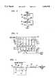
- FIG. 1is a block diagram of a prior art ISI-DFE
- FIG. 2is a block diagram of a prior art NP-DFE
- FIG. 3is a block diagram of a communications system that embodies the principles of the invention.
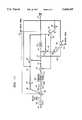
- FIG. 4is a block diagram of a hybrid DFE structure embodying the principles of the invention.
- FIG. 5is an illustrative flow diagram of an adaptation sequence for use in the hybrid DFE structure of FIG. 1 embodying the principles of the invention
- FIG. 6is a block diagram of feedforward filter 105 of FIG. 1, embodying the principles of the invention.
- FIG. 7is a block diagram of a precoder for use in transmitter 10 of FIG. 3;
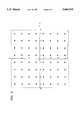
- FIG. 8is an illustrative signal point constellation
- FIG. 9is a block diagram of an embodiment of a hybrid DFE during the communications phase in accordance with the principles of this invention.
- FIG. 10is a block diagram Of another embodiment of a hybrid DFE during the communications phase
- FIG. 11is a block diagram of another embodiment of a hybrid DFE during the communications phase.
- FIG. 12is a flow chart of a retraining method.
- FIG. 1shows a prior art ISI-DFE that includes feedforward filter 50, adder 55, slicer 60, and ISI feedback filter 65.
- a received data signal for processingis applied to feed forward filter 50, via sampler 48 and line 49.
- Feedforward filter 50removes a portion of the ISI present in the received data signal.
- the output signal from feedforward filter 50is applied, via sampler 53, to adder 55, which, theoretically, subtracts the remaining portion of ISI removed by ISI feedback filter 65.
- Adder 55provides a signal on line 56 to slicer 60. The latter selects a particular data symbol as a function of the mapping of the signal on line 56 into a predefined constellation of data symbols (not shown).
- Slicer 60provides a data symbol every T seconds, where 1/T is the data symbol rate.
- This data symbolis an estimate of the transmitted symbol and is provided by slicer 60 on line 61 for processing by other receiver circuitry (not shown) to recover the actually transmitted data.
- this estimate of the transmitted symbolis also provided to ISI feedback filter 65. The latter uses this estimate to predict the amount of ISI to remove from the received signal. As long as this estimate of the currently transmitted symbol is, in fact, correct, there is no problem. However, if the estimate of the currently transmitted symbol is wrong, then the feedback section adds this error to the next received symbol and error propagation occurs.
- a form of non-linear precodingis typically used to minimize error propagation.
- precodingthere are two phases of receiver operation.
- the first phasethe "start-up,” or “training,” phase
- the ISI-DFE of the receiveradapts to a standard test signal received from a transmitter.
- the resulting coefficient values of the ISI-DFE --as represented by the notation I(z), as known in the artare transmitted back to the transmitter, e.g., over a reverse channel.
- the second phasei.e., the "communications" phase is entered.
- the transmitternow precodes the data before transmission using any of the well-known precoding techniques, e.g., Tomlinson precoding.
- the precoding techniqueutilizes the above-mentioned coefficient values, I(z), as determined by the ISI-DFE in the receiver. Similarly, the receiver processes any received signal in a complementary fashion to remove the precoding. However, typically, the ISI-DFE section is no longer used during the communications phase since the precoding in the transmitter is equivalently performing the feedback function and error propagation is no longer a problem.
- NP-DFE structureincludes linear equalizer (LE) 80, adder 85, slicer 90, adder 95, and NP feedback filter 75.
- LE 80linear equalizer
- LE 80theoretically removes all but a residual portion of the ISI present in the received data signal.
- the output signal from LE 80is applied, via sampler 83, to adder 85, which, theoretically, subtracts the remaining predictive portion of channel noise estimated by NP feedback filter 75.
- Adder 85provides a signal on line 86 to slicer 90.
- the latterselects a particular data symbol as a function of the mapping of the signal on line 86 into a predefined constellation of data symbols (not shown).
- Slicer 90provides a data symbol every T seconds, where 1/T is the data symbol rate.
- This data symbolis an estimate of the transmitted symbol and is provided by slicer 90 on line 91 for processing by other receiver circuitry (not shown) to recover the actually transmitted data. (If it is a coded signal such as trellis coding, the value at the input of the slicer is used in a Viterbi decoder).
- this estimate of the transmitted symbolis also provided to adder 95. The latter subtracts the estimate of the transmitted symbol from the ISI-reduced signal present on line 81 to provide an input signal to NP feedback filter 75.
- the latteruses this estimate to predict the amount of channel noise to remove from the received signal.
- error propagationis a problem, which is typically solved by the use of non-linear precoding in a transmitter that uses the N(z) coefficient values.
- the receiver structureis changed to one in which the linear equalizer is followed by a filter incorporating a 1+N(z) response.
- the NP-DFEis typically no longer used.
- transmitter 10transmits a signal to receiver 20, via communications channel 15.
- Receive 20includes a hybrid DFE.
- FIG. 4An illustrative hybrid DFE structure embodying the principles of the invention is shown in FIG. 4 for use in receiver 20.
- the hybrid DFE structureincludes an adaptive feedforward filter section that is followed by both an ISI predictive filter and a noise predictive filter in parallel.
- the other elements of the receiverare excluded from FIG. 4 for simplicity.
- the components of FIG. 4are well-known and will not be described in detail.
- feed forward filter section (FF) 105is typically a fractionally spaced equalizer and can also be a symbol-spaced equalizer for lesser performance and hardware complexity.
- sampler 108is a part of the fractionally spaced equalizer.
- the outputs of a filtering processare dependent upon the filter coefficients, which, in the case of FF 105, are represented by the notation F(z), as known in the art.
- FF 105is an adaptive filter, whose coefficients, F(z), are changed as a function of the adaptation signal present on line 136, described below.
- F(z)coefficients
- FF 105removes a portion of the ISI present in the received data signal.
- step 300only the ISI-DFE portion of the hybrid DFE of FIG. 4 is adapted.
- NP feedback filter 155is disabled via an NP control signal on line 154.
- the value of the output signal of NP feedback filter 155is presumed to be zero.
- the adaptation of ISI feedback filter 125 and FF 105is enabled via an ISI control signal on line 124. Consequently, during this first phase of training, effectively only an ISI-DFE is operating to remove any ISI present in the received training signal.
- the output signal from FF 105is applied, via sampler 108, to adder 110, which, theoretically, subtracts the remaining portion of ISI removed by ISI feedback filter 125 from the output signal of FF 105.
- Adder 110provides a signal on line 111.
- colored channel noiseis typically still present in this signal on line 111.
- the latter signalis applied to adder 115 and to adder 130 (described below). Since NP feedback filter 155 is disabled, there is no estimate of the colored channel noise present on line 156, i.e., the value associated with this signal is zero, and adder 115 simply passes through the signal from adder 110 to line 116.
- the signal on line 116is applied to slicer 120.
- Slicer 120selects a particular data symbol as a function of the mapping of the signal on line 116 to a point in a predefined constellation of data symbols (not shown).
- Slicer 120provides a data symbol every T seconds, where 1/T is the data symbol rate.
- This data symbolis an estimate of the received symbol and is provided by slicer 120 on line 121 for processing by other receiver circuitry (not shown) to recover the actually transmitted data, in this case the data representative of the training signal.
- the output of slicer 120is also provided to ISI feedback filter 125 and adders 130 and 145.
- ISI feedback filter 125predicts the amount of ISI present in the received signal and provides an IS I prediction signal to adder 110, via line 126.
- Adder 110removes the remaining portion of ISI from the received signal by subtracting the ISI prediction signal from the output signal of FF 105.
- Adder 130subtracts the estimated data symbol provided by slicer 120 from the ISI-reduced signal present on line 111 to provide an error signal, e1, on line 131.
- the latter signalrepresents the amount of ISI error and channel noise that has not been corrected by the operation of either FF 105, ISI feedback filter 125, or noise feedback filter 155.
- Error signal e1is used to adapt both FF 105 and ISI feedback filter 125 via multipliers 135 and 140, and is provided as an input signal to noise feedback filter 155 described below. It is assumed that the adaptation algorithms (not shown) of FF 105 and ISI feedback filter 125 conform to the use of MMSE, zero forcing, or it variations, as known in the art.
- Multiplier 135multiples the error signal e1 by a constant, or step size, ⁇ 1.
- the resulting signal provided on line 136is used to adapt FF 105.
- the signal on line 131is the input signal to noise feedback filter 155 (described below). Further the signal on line 131 is also provided to multiplier 140, which effectively multiples the signal e1 by the step size ⁇ 2.
- the resulting signal provided on line 141is used to adapt ISI feedback filter 125.
- ⁇ 1 and ⁇ 2are commonly set to equal or comparable values. Step sizes ⁇ 1 and ⁇ 2 are much smaller than step size ⁇ 3.
- step 310a comparison is made between the value of error signal e1 and a predefined constant E1.
- E1represents a desired ISI error rate and can either be empirically determined for a particular type of communications channel, or can be set to a specified communications system requirement. In this example, it is assumed the E1 is equal to 10 -7 for an uncoded case and 10 -3 for a coded case. If the value of the signal e1 is greater than or equal to E1, the ISI-DFE continues to adapt in step 300. However, if the value of the signal e1 is less than E1, the NP-DFE portion of the hybrid DFE of FIG. 4 is enabled and the ISI-DFE and FF 105 at this time can either keep adapting or be frozen.
- NP feedback filter 155is now enabled via the NP control signal on line 154. It should be noted that the ISI control signal on line 124 only controls the adaptation of FF 105 and ISI-feedback filter 125, these filters are still enabled and removing ISI based upon the coefficients values determined in step 300. In contrast, the NP control signal on line 154 controls the operation of NP feedback filter 154.
- Adder 145subtracts the estimated data symbol from the input signal to slicer 120 to provide error signal e2 on line 146.
- This error signalrepresents the amount of remaining channel noise that has not been corrected by the operation of noise feedback filter 155.
- Error signal e2is used to adapt noise feedback filter 155 and is provided as an input signal to multiplier 150. It is assumed that the adaptation algorithms (not shown) of noise feedback filter 155 conforms to the use of MMSE zero forcing, or its variations, as known in the art.
- Multiplier 150multiples the error signal e2 by a step size, ⁇ 3. The resulting signal provided on line 151 is used to adapt noise feedback filter 155.
- a comparisonis made between the value of error signal e2 and a predefined constant E2 in step 330.
- the constant E2represents a desired channel error rate and can either be empirically determined for a particular type of communications channel, or can be set to a specified communications system requirement. In this example, it is assumed that E2 is better than 10 -7 in an uncoded case and better than 10 -3 for a coded system. If the value of the signal e2 is greater than or equal to E2, the NP-DFE continues to adapt in step 320. However, if the value of the signal e2 is less than E2, the NP-DFE portion of the hybrid ends the initial adaptation process and proceeds to the communications phase.
- an adaptive filteris a delay line that includes a number of taps. Each tap represents a value of the received signal at a point in time, typically at intervals of T/k, where 1/T is the symbol rate and k is typically an integer and may be a fractional number.
- a generalized structure of FF 105is shown in FIG. 6.
- FF 105includes delay line 200, which includes K taps. The output of each tap is multiplied by a respective coefficient K i , the values of which are adapted as described above.
- the "major tap”is the center tap and is associated with the "current" symbol at the FF output.
- the center tapis represented by tap n+1.
- a feedforward filterperforms both "pre-cursor” filtering and "post-cursor” filtering.
- Pre-cursor filteringrepresents that portion of ISI that occurs due to symbols received before the current symbol.
- post-cursor filteringrepresents that portion of ISI that occurs due to symbols received after the current symbol.
- the post-cursor filteringis predictive in nature and is primarily performed by the ISI feedback filter of an ISI-DFE.
- the feedforward filter sectionalso performs post-cursor filtering which corresponds to the span of the post-cursor tail of a "theoretical" matched filter, there is a tension between these two filters, i.e., the feedforward filter section fights with the ISI-feedback filter when the two filters are adapted. Consequently, it is desirable to lessen the amount of post-cursor filtering performed by the feedforward filter section. Therefore, and in accordance with the inventive concept, the "major tap" is shifted from the center tap so that the number of pre-cursor taps is greater than the number of postcursor taps. Typically, only a few symbols need be reserved in the feedforward filter section for post-cursor filtering. As shown in FIG.
- taps that provide post-cursor filteringare provided by taps n-1, and n-2.
- the step size ⁇ 1which is used to multiply error signal e1
- the step size ⁇ 1 0 and ⁇ 1 1can be further divided into two different step sizes: ⁇ 1 0 and ⁇ 1 1 , where ⁇ 1 0 is associated with the post-cursor filtering and is selected to be less than ⁇ 2.
- the communications system of FIG. 3utilizes the well-known method of precoding to reduce the affect of error propagation on the performance of a DFE.
- "Tomlinson" precodingas known in the art is used in conjunction with the hybrid DFE of FIG. 4.
- An example of the precoder portion of transmitter 10is shown in FIG. 7.
- a data signalis applied to a Tomlinson precoder comprising adder 605, mod-2L element 610, and filter 615.
- the Tomlinson precoderfunctions as in the prior art.
- adder 605subtracts a signal developed by filter 615, described below, from the data signal.
- the output signal of adder 605is applied to mod-2L element 610, which performs as known in the art, to provide an output data symbol stream on line 611 to transmitter 621.
- mod-2L element 610maps the output signal on line 606 to a position in a signal point constellation. This mapping is performed using modulo 2L arithmetic, where L is the size of a signal point constellation.
- Transmitter 621includes the remaining portion of transmitter 10 and provides a modulated signal to communications channel 15.
- the output data symbol streamis also applied to filter 615, which filters this signal in accordance with the polynomial function, or filter response, C(z).
- the latteris transmitted from receiver 20 after the above described training phase, and represents the combination of the adaptation coefficients of I(z) and N(z).
- precodingis typically based upon adaptation coefficients determined during training. Once training is completed, these adaptation coefficients are sent back to the transmitter for use in the precoder. Consequently, since the precoder is now adapting for ISI and channel noise, the hybrid DFE structure of FIG. 4 must be modified. An illustrative modification for use during the communications phase is shown in FIG. 9, which shows a portion of receiver 20.
- the system responseis 1+I(z) since the post-cursor response remains uncorrected. That is, the output signal is the current symbol (represented by the number "1") plus post-cursor ISI.
- a feedforward filter sectionintroduces slightly colored noise. To whiten this slightly colored noise a 1+N(z) filter is used, represented by filter section 655. At this filter output, the system response is (1+I(z))(1+N(z)). Therefore, the residual response that a precoder needs to deal with is
- both I(z) and N(z)are calculated by receiver 20 and transmitted back to transmitter 10 during a respective training phase, where I(z) and N(z) are combined as shown in equation (1) to provide the filter response function for filter 615.
- a received precoded data signalis applied to FF 650.
- the latteris convolved with filter element 655, which has a filter response equal to (1+N(z)).
- the resultant output signal from filter element 655is applied to Tomlinson decoder 670, which provides a sequence of data symbols to slicer 675.
- the latterprovides an estimate of the transmitted data symbol to the remaining portion of receiver 20 (not shown).
- an error signalis developed by adder 680. This error signal is used to adapt FF 650.
- hybrid DFEmay be desirable to continue to adapt the hybrid DFE to small changes in the communications channel response even during the communications phase. For example, crosstalk from neighboring cable pairs may affect the channel condition after training was accomplished.
- An illustrative hybrid DFE structureis shown in FIG. 11. In this example, the I(z) and N(z) coefficients of the hybrid DFE of FIG. 4 are reset to zero after training to allow for continued adaptation during the communications phase.
- the hybrid DFE structure of FIG. 4adapts according to the method of FIG. 5.
- the hybrid DFEfirst compensates for the presence of ISI in the received training signal. After the ISI compensation completes, the hybrid DFE compensates for any remaining channel noise.
- this approachprovides coefficients such that I(z) dominates N(z). Therefore, and in accordance with the principles of the invention, only the dominate tap values are used by the transmitter during precoding in the communications phase--which reduces transmitter complexity by the filter element 615 of FIG. 7. At the receiver, the hardware complexity is also reduced since there is no need to add 1+N(z) filter in the forward path.
- FIG. 10provides a more practical solution to the realization of a hybrid DFE structure that approaches optimal performance.
- a portion of receiver 20is shown during the communications phase.
- FIG. 10is similar to FIG. 4 except for the removal of that circuitry associated with the ISI portion of the hybrid DFE, i.e., ISI-feedback filter 125, multiplier 140, adder 110, and the addition of Tomlinson decoder 810. Consequently, the NP-DFE portion of the hybrid DFE is kept active during the communications phase. Conveniently, the continued use of the NP-DFE in the receiver allows the receiver to track small changes in the channel during the communications phase.
- FIG. 10allows receiver 20 to track small changes in the channel response, it may be the case that larger changes in the channel response will occur. In this case, the feedback coefficients of FF 105 and NP-feedback filter 155 will increase in size. Although the communications system of FIG. 3 could simply perform a retrain in this situation, it would be beneficial to not recalculate the entire set of I(z) and N(z) coefficients and instead perform a "quick retrain.”
- FIG. 11shows a block diagram of an illustrative hybrid DFE for performing a quick retrain.
- a corresponding quick retrain methodis shown in FIG. 12.
- I 0 (z)the initial set of coefficients.
- the I(z) coefficients of ISI feedback filter 125are reset to zero.
- both the ISI-predictive filter and the NP-predictive filtercontinue to operate in the communications phase.
- receiver 20periodically monitors the size of the coefficients of ISI feedback filter 125, as represented by I 1 (z), in comparison to a predetermined size I 1 .
- receiver 20When I 1 (z) is greater than I 1 , receiver 20 notifies transmitter 10 that a "quick retrain" is about to be performed, freezes the ISI-predictive filter from further adaptation in step 908, and sends I 1 (z) to transmitter 10 in step 910. This notification can occur in any number of ways as known in the prior art, e.g., via a reverse channel used for sending control information.
- receiver 20resets I 1 (z) to zero. Since communication is still occuring, receiver 20 illustratively monitors the error rate in step 930 to determine when transmitter 10 has completed the quick retrain. When the the error rate is less than 10 -7 , receiver 20 enables adaptation of the ISI predictive filter and returns back to step 905.
- Transmitter 10receives the updated coefficient values, I 1 (z), in step 915 and simply adds I 1 (z) to the pre-existing I 0 (z) values in step 925. Consequently, a quicker retrain of the communications system has been accomplished.
- any one or more of those building blockscan be carried out using one or more appropriate programmed processors, e.g., a digital signal processor.
- N(z)is used by transmitter 10 for precoding
- the NP-DFE portion of the hybrid DFEadapts before the ISI-portion of the hybrid DFE.
- the corresponding hybrid DFE structure during the communications phaseshould include a filter section similar to filter element 655 of FIG. 9, which whitens the colored noise.
Landscapes
- Engineering & Computer Science (AREA)
- Computer Networks & Wireless Communication (AREA)
- Signal Processing (AREA)
- Physics & Mathematics (AREA)
- Spectroscopy & Molecular Physics (AREA)
- Power Engineering (AREA)
- Cable Transmission Systems, Equalization Of Radio And Reduction Of Echo (AREA)
- Filters That Use Time-Delay Elements (AREA)
- Transmission Systems Not Characterized By The Medium Used For Transmission (AREA)
- Digital Transmission Methods That Use Modulated Carrier Waves (AREA)
Abstract
Description
(1+I(z)(1+N)(z))-1,
C(z)=(1+I(z))(1+N(z))-1, (1)
Claims (5)
Priority Applications (9)
| Application Number | Priority Date | Filing Date | Title |
|---|---|---|---|
| US08/322,878US5604769A (en) | 1994-10-13 | 1994-10-13 | Hybrid equalizer arrangement for use in data communications equipment |
| CA002158185ACA2158185C (en) | 1994-10-13 | 1995-09-13 | Hybrid equalizer arrangement for use in data communications equipment |
| EP95307019AEP0707401B1 (en) | 1994-10-13 | 1995-10-03 | Precoding system and method for use in data communications equipment |
| DE69530739TDE69530739T2 (en) | 1994-10-13 | 1995-10-03 | Pre-coding system and method for a data transmission device |
| MX9504289AMX9504289A (en) | 1994-10-13 | 1995-10-10 | Hybrid equalizer arrangement for use in data communications equipment. |
| CN95117961ACN1123978A (en) | 1994-10-13 | 1995-10-10 | A hybrid equalizer arrangement for use in data aom unications equipment |
| IL11558895AIL115588A (en) | 1994-10-13 | 1995-10-12 | Hybrid arrangement apparatus for use in data communications equipment |
| KR1019950035510AKR100346530B1 (en) | 1994-10-13 | 1995-10-12 | Hybrid equalizer device for datacom equipment |
| JP29064095AJP3195529B2 (en) | 1994-10-13 | 1995-10-13 | Apparatus and method for use in a data communication device |
Applications Claiming Priority (1)
| Application Number | Priority Date | Filing Date | Title |
|---|---|---|---|
| US08/322,878US5604769A (en) | 1994-10-13 | 1994-10-13 | Hybrid equalizer arrangement for use in data communications equipment |
Publications (1)
| Publication Number | Publication Date |
|---|---|
| US5604769Atrue US5604769A (en) | 1997-02-18 |
Family
ID=23256838
Family Applications (1)
| Application Number | Title | Priority Date | Filing Date |
|---|---|---|---|
| US08/322,878Expired - LifetimeUS5604769A (en) | 1994-10-13 | 1994-10-13 | Hybrid equalizer arrangement for use in data communications equipment |
Country Status (9)
| Country | Link |
|---|---|
| US (1) | US5604769A (en) |
| EP (1) | EP0707401B1 (en) |
| JP (1) | JP3195529B2 (en) |
| KR (1) | KR100346530B1 (en) |
| CN (1) | CN1123978A (en) |
| CA (1) | CA2158185C (en) |
| DE (1) | DE69530739T2 (en) |
| IL (1) | IL115588A (en) |
| MX (1) | MX9504289A (en) |
Cited By (44)
| Publication number | Priority date | Publication date | Assignee | Title |
|---|---|---|---|---|
| US5742642A (en)* | 1996-10-29 | 1998-04-21 | Telefonaktiebolaget Lm Ericsson | Signal processing method and apparatus for reducing equalizer error |
| US5852630A (en)* | 1997-07-17 | 1998-12-22 | Globespan Semiconductor, Inc. | Method and apparatus for a RADSL transceiver warm start activation procedure with precoding |
| WO1999005807A1 (en)* | 1997-07-22 | 1999-02-04 | Globespan Semiconductor Inc. | Adaptive precoding system and method to compensate for changes in a communications channel |
| US5995543A (en)* | 1997-06-30 | 1999-11-30 | Stmicroelectronics N.V. | Constrained fixed delay tree search receiver for a MTR=2 encoded communication channel |
| US6151368A (en)* | 1999-03-22 | 2000-11-21 | Sicom, Inc. | Phase-noise compensated digital communication receiver and method therefor |
| US6185250B1 (en) | 1999-03-10 | 2001-02-06 | Lucent Technologies Inc. | Training of level learning modems |
| US6249544B1 (en)* | 1998-11-13 | 2001-06-19 | Broadcom Corporation | System and method for high-speed decoding and ISI compensation in a multi-pair transceiver system |
| US6324232B1 (en)* | 1998-01-15 | 2001-11-27 | Pc-Tel, Inc. | Adaptive DC-compensation |
| US20020044598A1 (en)* | 1999-12-27 | 2002-04-18 | Tioga Technologies, Inc. | Data communication system with adaptive precoding |
| US6400761B1 (en) | 1999-09-15 | 2002-06-04 | Princeton University | Method and apparatus for adaptively compensating channel or system variations in precoded communications system |
| US6466631B1 (en)* | 1998-01-28 | 2002-10-15 | Infineon Technologies Ag | Device and method of changing the noise characteristic in a receiver of a data transmission system |
| US20020150155A1 (en)* | 2001-02-26 | 2002-10-17 | Itzhak Florentin | Convergence speed, lowering the excess noise and power consumption of equalizers |
| US20020196877A1 (en)* | 2001-03-29 | 2002-12-26 | Applied Wave Research, Inc. | Method and apparatus for characterizing the distortion produced by electronic equipment |
| US6570917B1 (en) | 1999-03-10 | 2003-05-27 | Agere Systems Inc. | Equalizer training in the presence of network impairment |
| US6600780B1 (en) | 1999-03-10 | 2003-07-29 | Agere Systems Inc. | Apparatus and method for adapting a filter of an analog modem |
| US20030185195A1 (en)* | 1998-10-07 | 2003-10-02 | Dowling Eric Morgan | Virtual connection of a remote unit to a server |
| US6683913B1 (en) | 1999-12-30 | 2004-01-27 | Tioga Technologies Inc. | Narrowband noise canceller |
| US6690739B1 (en) | 2000-01-14 | 2004-02-10 | Shou Yee Mui | Method for intersymbol interference compensation |
| WO2004025917A1 (en)* | 2002-09-10 | 2004-03-25 | Berkana Wireless Korea Inc. | High-speed adaptive equalizer |
| US20040087308A1 (en)* | 2002-01-29 | 2004-05-06 | Olav Tirkkonen | Data transfer method in radio system |
| US6754293B1 (en)* | 1995-06-01 | 2004-06-22 | Nokia Mobile Phones, Ltd. | Method and circuit arrangement for processing a signal containing interference |
| US20040120394A1 (en)* | 2002-12-18 | 2004-06-24 | Miao George J. | Decision-feedback equalizer |
| US6778599B1 (en) | 2000-03-09 | 2004-08-17 | Tioga Technologies | Digital transceiver with multi-rate processing |
| US20040181738A1 (en)* | 1998-11-13 | 2004-09-16 | Agazzi Oscar E. | System and method for trellis decoding in a multi-pair transceiver system |
| US20050046219A1 (en)* | 2003-08-29 | 2005-03-03 | Livingston Thomas John | Tailgate step |
| US6870881B1 (en) | 2000-08-24 | 2005-03-22 | Marvell International Ltd. | Feedforward equalizer for DFE based detector |
| US6876699B1 (en)* | 2000-08-29 | 2005-04-05 | Lucent Technologies Inc. | Filter circuit for a bit pump and method of configuring the same |
| US6894989B1 (en) | 2000-08-29 | 2005-05-17 | Agere Systems Inc. | Separation circuit for an echo canceling system and method of operating the same |
| US20050227739A1 (en)* | 1998-11-17 | 2005-10-13 | Dowling Eric M | Geographical web browser, methods, apparatus and systems |
| US6970511B1 (en) | 2000-08-29 | 2005-11-29 | Lucent Technologies Inc. | Interpolator, a resampler employing the interpolator and method of interpolating a signal associated therewith |
| US6973146B1 (en) | 2000-08-29 | 2005-12-06 | Lucent Technologies Inc. | Resampler for a bit pump and method of resampling a signal associated therewith |
| US6983047B1 (en) | 2000-08-29 | 2006-01-03 | Lucent Technologies Inc. | Echo canceling system for a bit pump and method of operating the same |
| US20060029174A1 (en)* | 2001-04-30 | 2006-02-09 | Agere Systems Incorporated | Transceiver having a jitter control processor with a receiver stage and a method of operation thereof |
| US20060045221A1 (en)* | 2004-08-31 | 2006-03-02 | Nir Sasson | System and method of removing discrete spurious signals in cable broadband and other RF environments |
| US20060245487A1 (en)* | 1998-11-13 | 2006-11-02 | Agazzi Oscar E | High-speed decoder for a multi-pair gigabit transceiver |
| US20070242740A1 (en)* | 2006-04-17 | 2007-10-18 | Kim Jin H | Reducing equalizer error propagation with a low complexity soft output Viterbi decoder |
| US20070263715A1 (en)* | 2006-04-17 | 2007-11-15 | Kim Jin H | Dual pDFE system with forward-backward viterbi |
| US20080317179A1 (en)* | 2000-11-03 | 2008-12-25 | Agere Systems Inc. | Method And Apparatus For Pipelined Joint Equalization And Decoding For Gigabit Communications |
| US20090110047A1 (en)* | 2007-10-31 | 2009-04-30 | Agere Systems Inc. | Demodulator with configurable adaptive equalizer |
| US20120257691A1 (en)* | 2001-06-01 | 2012-10-11 | The Board Of Trustees Of The Leland Stanford Junior University | Dynamic digital communication system control |
| US8891607B2 (en) | 2012-09-06 | 2014-11-18 | Avago Technologies General Ip (Singapore) Pte. Ltd. | Feed forward equalizer tap weight adaptation based on channel estimation |
| US8938035B1 (en) | 2012-02-29 | 2015-01-20 | Marvell International Ltd. | System and method for transferring data over a two-pair communication system |
| US8964827B2 (en) | 2013-03-07 | 2015-02-24 | Avago Technologies General Ip (Singapore) Pte. Ltd. | Adaptation of equalizer settings using error signals sampled at several different phases |
| US10771295B2 (en)* | 2003-12-17 | 2020-09-08 | Rambus Inc. | High speed signaling system with adaptive transmit pre-emphasis |
Families Citing this family (18)
| Publication number | Priority date | Publication date | Assignee | Title |
|---|---|---|---|---|
| US5694437A (en)* | 1995-10-10 | 1997-12-02 | Motorola, Inc. | Device and method for data signal detection in the presence of distortion and interference in communication systems |
| US6167082A (en)* | 1997-03-06 | 2000-12-26 | Level One Communications, Inc. | Adaptive equalizers and methods for carrying out equalization with a precoded transmitter |
| US6069917A (en)* | 1997-05-23 | 2000-05-30 | Lucent Technologies Inc. | Blind training of a decision feedback equalizer |
| WO1999039334A1 (en)* | 1998-01-28 | 1999-08-05 | Fujitsu Limited | Error propagation suppressing method in decision feedback equalization and magnetic recording / reproducing apparatus using the method |
| FR2775144B1 (en)* | 1998-02-19 | 2000-04-14 | Telediffusion Fse | METHOD AND DEVICE FOR PREDICTIVE SELF-TEACHING EQUALIZATION OF A TRANSMISSION CHANNEL OF A BROADCASTED RADIO SIGNAL |
| US6724844B1 (en)* | 1998-06-30 | 2004-04-20 | Koninklijke Philips Electronics N.V. | Method and device for improving DFE performance in a trellis-coded system |
| KR100442818B1 (en)* | 1998-10-14 | 2004-09-18 | 삼성전자주식회사 | Sequential Update Adaptive Equalizer and Method |
| GB2347054B (en)* | 1999-02-19 | 2003-12-03 | Adaptive Broadband Ltd | Stabilized precoder for data transmission |
| JP2003224496A (en)* | 2002-01-29 | 2003-08-08 | Matsushita Electric Ind Co Ltd | Transmission / reception device, wireless communication system, and transmission / reception method |
| US7450636B2 (en) | 2002-09-05 | 2008-11-11 | Avago Technologies General Ip (Singapore) Pte. Ltd. | Adaptive transmit equalizer |
| EP1675337A1 (en)* | 2004-10-15 | 2006-06-28 | Mitsubishi Electric Information Technology Centre Europe B.V. | Frequency domain equaliser for single-carrier signals |
| US7443914B2 (en)* | 2004-10-27 | 2008-10-28 | Yehuda Azenkot | DFE to FFE equalization coefficient conversion process for DOCSIS 2.0 |
| CN101091364A (en)* | 2004-12-30 | 2007-12-19 | 英特尔公司 | Prescribed response precoding for channels with intersymbol interference |
| KR100754967B1 (en)* | 2006-01-23 | 2007-09-04 | 학교법인 포항공과대학교 | Integral receiver with adaptive decision feedback equalizer function to remove inter-signal interference and high frequency noise at the same time |
| US7715669B2 (en)* | 2007-10-17 | 2010-05-11 | Avago Technologies Fiber Ip (Singapore) Pte. Ltd. | Fiber optic link, a transceiver for use in the link, and methods for designing and constructing fiber optic links and transceivers |
| WO2009080841A1 (en)* | 2007-12-20 | 2009-07-02 | Sidsa (Semiconductores Investigación Y Diseño, S.A.) | Method and apparatus for starting and dynamically adapting equalization with precoding in a digital communications system including a feedback channel |
| US10374844B1 (en)* | 2018-03-08 | 2019-08-06 | Nxp B.V. | Signal-equalization with noise-whitening filter |
| KR102778875B1 (en) | 2022-03-28 | 2025-03-11 | 한국전자통신연구원 | Method of equalization for high-speed processing and equalizer |
Citations (7)
| Publication number | Priority date | Publication date | Assignee | Title |
|---|---|---|---|---|
| US5249200A (en)* | 1991-07-30 | 1993-09-28 | Codex Corporation | Device and method for combining precoding with symbol-rate spectral shaping |
| US5388124A (en)* | 1992-06-12 | 1995-02-07 | University Of Maryland | Precoding scheme for transmitting data using optimally-shaped constellations over intersymbol-interference channels |
| US5414733A (en)* | 1993-12-20 | 1995-05-09 | Adtran | Decision feedback equalizer employing fixed ratio postcursor taps for minimizing noise and intersymbol interference in signals conveyed over high speed data service loop |
| US5446758A (en)* | 1993-07-08 | 1995-08-29 | Motorola, Inc. | Device and method for precoding |
| US5455839A (en)* | 1991-12-27 | 1995-10-03 | Motorola, Inc. | Device and method for precoding |
| US5488633A (en)* | 1993-06-14 | 1996-01-30 | At&T Corp. | Intersymbol interference channel coding scheme |
| US5513216A (en)* | 1994-10-13 | 1996-04-30 | At&T Corp. | Hybrid equalizer arrangement for use in data communications equipment |
- 1994
- 1994-10-13USUS08/322,878patent/US5604769A/ennot_activeExpired - Lifetime
- 1995
- 1995-09-13CACA002158185Apatent/CA2158185C/ennot_activeExpired - Fee Related
- 1995-10-03EPEP95307019Apatent/EP0707401B1/ennot_activeExpired - Lifetime
- 1995-10-03DEDE69530739Tpatent/DE69530739T2/ennot_activeExpired - Lifetime
- 1995-10-10CNCN95117961Apatent/CN1123978A/enactivePending
- 1995-10-10MXMX9504289Apatent/MX9504289A/ennot_activeIP Right Cessation
- 1995-10-12ILIL11558895Apatent/IL115588A/ennot_activeIP Right Cessation
- 1995-10-12KRKR1019950035510Apatent/KR100346530B1/ennot_activeExpired - Fee Related
- 1995-10-13JPJP29064095Apatent/JP3195529B2/ennot_activeExpired - Fee Related
Patent Citations (7)
| Publication number | Priority date | Publication date | Assignee | Title |
|---|---|---|---|---|
| US5249200A (en)* | 1991-07-30 | 1993-09-28 | Codex Corporation | Device and method for combining precoding with symbol-rate spectral shaping |
| US5455839A (en)* | 1991-12-27 | 1995-10-03 | Motorola, Inc. | Device and method for precoding |
| US5388124A (en)* | 1992-06-12 | 1995-02-07 | University Of Maryland | Precoding scheme for transmitting data using optimally-shaped constellations over intersymbol-interference channels |
| US5488633A (en)* | 1993-06-14 | 1996-01-30 | At&T Corp. | Intersymbol interference channel coding scheme |
| US5446758A (en)* | 1993-07-08 | 1995-08-29 | Motorola, Inc. | Device and method for precoding |
| US5414733A (en)* | 1993-12-20 | 1995-05-09 | Adtran | Decision feedback equalizer employing fixed ratio postcursor taps for minimizing noise and intersymbol interference in signals conveyed over high speed data service loop |
| US5513216A (en)* | 1994-10-13 | 1996-04-30 | At&T Corp. | Hybrid equalizer arrangement for use in data communications equipment |
Non-Patent Citations (4)
| Title |
|---|
| IEEE, "Approximate maximum likelihood sequence estimators for time dispersive channels", N. A. Zervos, et al., 1983 International Electrical, Electronics Conference Proceedings, pp. 62-65, vol. 1; Publication Date: 1983. |
| IEEE, Approximate maximum likelihood sequence estimators for time dispersive channels , N. A. Zervos, et al., 1983 International Electrical, Electronics Conference Proceedings, pp. 62 65, vol. 1; Publication Date: 1983.* |
| ISCAS, "Design and Performance of an All-Digital Adaptive 2.048 MBIT/S Data Transmission System Using Noise Prediction", Graf et al., ISCAS 1989, pp. 1808-1812. |
| ISCAS, Design and Performance of an All Digital Adaptive 2.048 MBIT/S Data Transmission System Using Noise Prediction , Graf et al., ISCAS 1989, pp. 1808 1812.* |
Cited By (106)
| Publication number | Priority date | Publication date | Assignee | Title |
|---|---|---|---|---|
| US6754293B1 (en)* | 1995-06-01 | 2004-06-22 | Nokia Mobile Phones, Ltd. | Method and circuit arrangement for processing a signal containing interference |
| US5742642A (en)* | 1996-10-29 | 1998-04-21 | Telefonaktiebolaget Lm Ericsson | Signal processing method and apparatus for reducing equalizer error |
| US5995543A (en)* | 1997-06-30 | 1999-11-30 | Stmicroelectronics N.V. | Constrained fixed delay tree search receiver for a MTR=2 encoded communication channel |
| US5852630A (en)* | 1997-07-17 | 1998-12-22 | Globespan Semiconductor, Inc. | Method and apparatus for a RADSL transceiver warm start activation procedure with precoding |
| WO1999004501A1 (en)* | 1997-07-17 | 1999-01-28 | Globespan Semiconductor Inc. | Method and apparatus for a radsl transceiver warm start activation procedure with precoding |
| WO1999005807A1 (en)* | 1997-07-22 | 1999-02-04 | Globespan Semiconductor Inc. | Adaptive precoding system and method to compensate for changes in a communications channel |
| US6243425B1 (en) | 1997-07-22 | 2001-06-05 | Globespan Technologies, Inc. | Adaptive precoding system and method for equalizing communication signal |
| US6324232B1 (en)* | 1998-01-15 | 2001-11-27 | Pc-Tel, Inc. | Adaptive DC-compensation |
| US6466631B1 (en)* | 1998-01-28 | 2002-10-15 | Infineon Technologies Ag | Device and method of changing the noise characteristic in a receiver of a data transmission system |
| US20090083376A1 (en)* | 1998-10-07 | 2009-03-26 | Eric Morgan Dowlmg | Application-layer evaluation of communications received by a mobile device |
| US20050025184A1 (en)* | 1998-10-07 | 2005-02-03 | Dowling Eric Morgan | Virtual connection of a remote unit to a server |
| US20050041687A1 (en)* | 1998-10-07 | 2005-02-24 | Dowling Eric Morgan | Virtual connection of a remote unit to a server |
| US20080310392A1 (en)* | 1998-10-07 | 2008-12-18 | Eric Morgan Dowling | Virtual connection of a remote unit to a server |
| US8266296B2 (en) | 1998-10-07 | 2012-09-11 | East Texas Technology Partners, Lp | Application-layer evaluation of communications received by a mobile device |
| US20030185195A1 (en)* | 1998-10-07 | 2003-10-02 | Dowling Eric Morgan | Virtual connection of a remote unit to a server |
| US8291010B2 (en) | 1998-10-07 | 2012-10-16 | East Texas Technology Partners, Lp | Virtual connection of a remote unit to a server |
| US20090044070A1 (en)* | 1998-11-13 | 2009-02-12 | Agazzi Oscar E | System and method for trellis decoding in a multi-pair transceiver system |
| US20100208788A1 (en)* | 1998-11-13 | 2010-08-19 | Azazzi Oscar E | System and method for high-speed decoding and isi compensation in a multi-pair transceiver system |
| US7434134B2 (en) | 1998-11-13 | 2008-10-07 | Broadcom Corporation | System and method for trellis decoding in a multi-pair transceiver system |
| US20060245487A1 (en)* | 1998-11-13 | 2006-11-02 | Agazzi Oscar E | High-speed decoder for a multi-pair gigabit transceiver |
| US8320443B2 (en) | 1998-11-13 | 2012-11-27 | Broadcom Corporation | System and method for high-speed decoding and ISI compensation in a multi-pair transceiver system |
| US7466751B2 (en) | 1998-11-13 | 2008-12-16 | Broadcom Corporation | System and method for high-speed decoding and ISI compensation in a multi-pair transceiver system |
| US20060034402A1 (en)* | 1998-11-13 | 2006-02-16 | Azazzi Oscar E | System and method for high-speed decoding and ISI compensation in a multi-pair transceiver system |
| US20090067559A1 (en)* | 1998-11-13 | 2009-03-12 | Azazzi Oscar E | System and method for high-speed decoding and isi compensation in a multi-pair transceiver system |
| US7630434B2 (en) | 1998-11-13 | 2009-12-08 | Broadcom Corporation | High-speed decoder for a multi-pair gigabit transceiver |
| US20100086019A1 (en)* | 1998-11-13 | 2010-04-08 | Agazzi Oscar E | High-Speed Decoder for a Multi-Pair Gigabit Transceiver |
| US8259787B2 (en) | 1998-11-13 | 2012-09-04 | Broadcom Corporation | High-speed decoder for a multi-pair gigabit transceiver |
| US6947482B2 (en) | 1998-11-13 | 2005-09-20 | Broadcom Corporation | System and method for high-speed decoding and ISI compensation in a multi-pair transceiver system |
| US20040181738A1 (en)* | 1998-11-13 | 2004-09-16 | Agazzi Oscar E. | System and method for trellis decoding in a multi-pair transceiver system |
| US20010019584A1 (en)* | 1998-11-13 | 2001-09-06 | Broadcom Corporation | System and method for high-speed decoding and ISI compensation in a multi-pair transceiver system |
| US6249544B1 (en)* | 1998-11-13 | 2001-06-19 | Broadcom Corporation | System and method for high-speed decoding and ISI compensation in a multi-pair transceiver system |
| US8201045B2 (en) | 1998-11-13 | 2012-06-12 | Broadcom Corporation | System and method for trellis decoding in a multi-pair transceiver system |
| US7711077B2 (en) | 1998-11-13 | 2010-05-04 | Broadcom Corporation | System and method for high-speed decoding and ISI compensation in a multi-pair transceiver system |
| US20060094443A1 (en)* | 1998-11-17 | 2006-05-04 | Dowling Eric M | Geographical web browser, methods, apparatus and systems |
| US7058395B2 (en) | 1998-11-17 | 2006-06-06 | Eric Morgan Dowling | Geographical web browser, methods, apparatus and systems |
| US7292844B2 (en) | 1998-11-17 | 2007-11-06 | Geobrowser Innovations, Lp | Geographical web browser, methods, apparatus and systems |
| US20050227739A1 (en)* | 1998-11-17 | 2005-10-13 | Dowling Eric M | Geographical web browser, methods, apparatus and systems |
| US20070155406A1 (en)* | 1998-11-17 | 2007-07-05 | Dowling Eric M | Geographical web browser, methods, apparatus and systems |
| US7215947B2 (en) | 1998-11-17 | 2007-05-08 | Eric Morgan Dowling | Geographical web browser, methods, apparatus and systems |
| US7212811B2 (en) | 1998-11-17 | 2007-05-01 | Eric Morgan Dowling | Geographical web browser, methods, apparatus and systems |
| US6983139B2 (en) | 1998-11-17 | 2006-01-03 | Eric Morgan Dowling | Geographical web browser, methods, apparatus and systems |
| US20070064644A1 (en)* | 1998-11-17 | 2007-03-22 | Dowling Eric M | Geographical web browser, methods, apparatus and systems |
| US8369263B2 (en) | 1998-11-17 | 2013-02-05 | E.O. Communication Fund, Llc | Geographical web browser, methods, apparatus and systems |
| US20080194240A1 (en)* | 1998-11-17 | 2008-08-14 | Eric Morgan Dowling | Geographical web browser, methods, apparatus and systems |
| US7142843B2 (en) | 1998-11-17 | 2006-11-28 | Eric Morgan Dowling | Geographical web browser, methods, apparatus and systems |
| US8190170B2 (en) | 1998-11-17 | 2012-05-29 | E.O. Communication Fund, Llc | Geographical web browser, methods, apparatus and systems |
| US6600780B1 (en) | 1999-03-10 | 2003-07-29 | Agere Systems Inc. | Apparatus and method for adapting a filter of an analog modem |
| US6570917B1 (en) | 1999-03-10 | 2003-05-27 | Agere Systems Inc. | Equalizer training in the presence of network impairment |
| US6185250B1 (en) | 1999-03-10 | 2001-02-06 | Lucent Technologies Inc. | Training of level learning modems |
| US6151368A (en)* | 1999-03-22 | 2000-11-21 | Sicom, Inc. | Phase-noise compensated digital communication receiver and method therefor |
| US6363124B1 (en) | 1999-03-22 | 2002-03-26 | Sicom, Inc. | Phase-noise compensated digital communication receiver and method therefor |
| US6400761B1 (en) | 1999-09-15 | 2002-06-04 | Princeton University | Method and apparatus for adaptively compensating channel or system variations in precoded communications system |
| US6987803B2 (en)* | 1999-12-27 | 2006-01-17 | Tioga Technologies, Inc. | Data communication system with adaptive precoding |
| US20020044598A1 (en)* | 1999-12-27 | 2002-04-18 | Tioga Technologies, Inc. | Data communication system with adaptive precoding |
| US6590933B1 (en) | 1999-12-27 | 2003-07-08 | Tioga Technologies Ltd. | Adaptive decision-feedback equalizer with error-predictor for improved convergence |
| US6683913B1 (en) | 1999-12-30 | 2004-01-27 | Tioga Technologies Inc. | Narrowband noise canceller |
| US6690739B1 (en) | 2000-01-14 | 2004-02-10 | Shou Yee Mui | Method for intersymbol interference compensation |
| US6778599B1 (en) | 2000-03-09 | 2004-08-17 | Tioga Technologies | Digital transceiver with multi-rate processing |
| US8750367B1 (en) | 2000-08-24 | 2014-06-10 | Marvell International Ltd. | Transceiver with single coefficient based equalizer taps |
| US8031765B1 (en) | 2000-08-24 | 2011-10-04 | Marvell International Ltd. | Feedforward equalizer for DFE based detector |
| US7426236B1 (en) | 2000-08-24 | 2008-09-16 | Marvell International Ltd. | Feedforward equalizer for DFE based detector |
| US9020025B1 (en) | 2000-08-24 | 2015-04-28 | Marvell International Ltd. | Transceiver with single coefficient based equalizer taps |
| US8315301B1 (en) | 2000-08-24 | 2012-11-20 | Marvell International Ltd. | Feedforward equalizer for DFE based detector |
| US6870881B1 (en) | 2000-08-24 | 2005-03-22 | Marvell International Ltd. | Feedforward equalizer for DFE based detector |
| US6983047B1 (en) | 2000-08-29 | 2006-01-03 | Lucent Technologies Inc. | Echo canceling system for a bit pump and method of operating the same |
| US20060023821A1 (en)* | 2000-08-29 | 2006-02-02 | Lucent Technologies Inc. | Resampler for a bit pump and method of resampling a signal associated therewith |
| US20060039550A1 (en)* | 2000-08-29 | 2006-02-23 | Lucent Technologies Inc. | Echo canceling system for a bit pump and method of operating the same |
| US6876699B1 (en)* | 2000-08-29 | 2005-04-05 | Lucent Technologies Inc. | Filter circuit for a bit pump and method of configuring the same |
| US6894989B1 (en) | 2000-08-29 | 2005-05-17 | Agere Systems Inc. | Separation circuit for an echo canceling system and method of operating the same |
| US7542536B2 (en) | 2000-08-29 | 2009-06-02 | Alcatel-Lucent Usa Inc. | Resampler for a bit pump and method of resampling a signal associated therewith |
| US6973146B1 (en) | 2000-08-29 | 2005-12-06 | Lucent Technologies Inc. | Resampler for a bit pump and method of resampling a signal associated therewith |
| US6970511B1 (en) | 2000-08-29 | 2005-11-29 | Lucent Technologies Inc. | Interpolator, a resampler employing the interpolator and method of interpolating a signal associated therewith |
| US7913154B2 (en)* | 2000-11-03 | 2011-03-22 | Agere Systems Inc. | Method and apparatus for pipelined joint equalization and decoding for gigabit communications |
| US20080317179A1 (en)* | 2000-11-03 | 2008-12-25 | Agere Systems Inc. | Method And Apparatus For Pipelined Joint Equalization And Decoding For Gigabit Communications |
| US20020150155A1 (en)* | 2001-02-26 | 2002-10-17 | Itzhak Florentin | Convergence speed, lowering the excess noise and power consumption of equalizers |
| US7577192B2 (en)* | 2001-03-29 | 2009-08-18 | Applied Wave Research, Inc. | Method and apparatus for characterizing the distortion produced by electronic equipment |
| US20020196877A1 (en)* | 2001-03-29 | 2002-12-26 | Applied Wave Research, Inc. | Method and apparatus for characterizing the distortion produced by electronic equipment |
| US7406143B2 (en) | 2001-04-30 | 2008-07-29 | Agere Systems Inc. | Transceiver having a jitter control processor with a receiver stage and a method of operation thereof |
| US20060029174A1 (en)* | 2001-04-30 | 2006-02-09 | Agere Systems Incorporated | Transceiver having a jitter control processor with a receiver stage and a method of operation thereof |
| US10404300B2 (en) | 2001-06-01 | 2019-09-03 | The Board Of Trustees Of The Leland Stanford Junior University | Dynamic digital communication system control |
| US8681897B2 (en)* | 2001-06-01 | 2014-03-25 | The Board Of Trustees Of The Leland Stanford Junior University | Dynamic digital communication system control |
| US10938427B2 (en) | 2001-06-01 | 2021-03-02 | The Board Of Trustees Of The Leland Stanford Junior University | Dynamic digital communication system control |
| US9160385B2 (en) | 2001-06-01 | 2015-10-13 | The Board Of Trustees Of The Leland Stanford Junior University | Dynamic digital communication system control |
| US20120257691A1 (en)* | 2001-06-01 | 2012-10-11 | The Board Of Trustees Of The Leland Stanford Junior University | Dynamic digital communication system control |
| US9843348B2 (en) | 2001-06-01 | 2017-12-12 | The Board Of Trustees Of The Leland Stanford Junior University | Dynamic digital communication system control |
| US20040087308A1 (en)* | 2002-01-29 | 2004-05-06 | Olav Tirkkonen | Data transfer method in radio system |
| WO2004025917A1 (en)* | 2002-09-10 | 2004-03-25 | Berkana Wireless Korea Inc. | High-speed adaptive equalizer |
| US20040120394A1 (en)* | 2002-12-18 | 2004-06-24 | Miao George J. | Decision-feedback equalizer |
| US20050046219A1 (en)* | 2003-08-29 | 2005-03-03 | Livingston Thomas John | Tailgate step |
| US11233678B2 (en) | 2003-12-17 | 2022-01-25 | Rambus Inc. | High speed signaling system with adaptive transmit pre-emphasis |
| US11706061B2 (en) | 2003-12-17 | 2023-07-18 | Rambus Inc. | High speed signaling system with adaptive transmit pre-emphasis |
| US10771295B2 (en)* | 2003-12-17 | 2020-09-08 | Rambus Inc. | High speed signaling system with adaptive transmit pre-emphasis |
| US20060045221A1 (en)* | 2004-08-31 | 2006-03-02 | Nir Sasson | System and method of removing discrete spurious signals in cable broadband and other RF environments |
| US7428281B2 (en)* | 2004-08-31 | 2008-09-23 | Texas Instruments Incorporated | System and method of removing discrete spurious signals in cable broadband and other RF environments |
| US7697604B2 (en)* | 2006-04-17 | 2010-04-13 | Techwell, Inc. | Dual pDFE system with forward-backward viterbi |
| US20070242740A1 (en)* | 2006-04-17 | 2007-10-18 | Kim Jin H | Reducing equalizer error propagation with a low complexity soft output Viterbi decoder |
| US8194800B2 (en) | 2006-04-17 | 2012-06-05 | Intersil Americas Inc | Reducing equalizer error propagation with a low complexity soft output viterbi decoder |
| US20070263715A1 (en)* | 2006-04-17 | 2007-11-15 | Kim Jin H | Dual pDFE system with forward-backward viterbi |
| US20100266007A1 (en)* | 2006-04-17 | 2010-10-21 | Techwell, Inc. | Dual pdfe system with forward-backward viterbi |
| US7697642B2 (en)* | 2006-04-17 | 2010-04-13 | Techwell, Inc. | Reducing equalizer error propagation with a low complexity soft output Viterbi decoder |
| US8005136B2 (en) | 2006-04-17 | 2011-08-23 | Intersil Americas Inc. | Dual PDFE system with forward-backward Viterbi |
| US7881365B2 (en)* | 2007-10-31 | 2011-02-01 | Agere Systems Inc. | Demodulator with configurable adaptive equalizer |
| US20090110047A1 (en)* | 2007-10-31 | 2009-04-30 | Agere Systems Inc. | Demodulator with configurable adaptive equalizer |
| US8938035B1 (en) | 2012-02-29 | 2015-01-20 | Marvell International Ltd. | System and method for transferring data over a two-pair communication system |
| US8891607B2 (en) | 2012-09-06 | 2014-11-18 | Avago Technologies General Ip (Singapore) Pte. Ltd. | Feed forward equalizer tap weight adaptation based on channel estimation |
| US8964827B2 (en) | 2013-03-07 | 2015-02-24 | Avago Technologies General Ip (Singapore) Pte. Ltd. | Adaptation of equalizer settings using error signals sampled at several different phases |
Also Published As
| Publication number | Publication date |
|---|---|
| JP3195529B2 (en) | 2001-08-06 |
| MX9504289A (en) | 1997-01-31 |
| EP0707401B1 (en) | 2003-05-14 |
| CA2158185A1 (en) | 1996-04-14 |
| EP0707401A3 (en) | 1998-01-28 |
| EP0707401A2 (en) | 1996-04-17 |
| KR100346530B1 (en) | 2002-12-06 |
| DE69530739T2 (en) | 2004-03-18 |
| KR960016303A (en) | 1996-05-22 |
| JPH08274724A (en) | 1996-10-18 |
| CN1123978A (en) | 1996-06-05 |
| IL115588A0 (en) | 1996-01-19 |
| CA2158185C (en) | 1999-09-07 |
| IL115588A (en) | 1999-08-17 |
| DE69530739D1 (en) | 2003-06-18 |
Similar Documents
| Publication | Publication Date | Title |
|---|---|---|
| US5604769A (en) | Hybrid equalizer arrangement for use in data communications equipment | |
| US5513216A (en) | Hybrid equalizer arrangement for use in data communications equipment | |
| US5881108A (en) | Adaptive pre-equalizer for use in data communications equipment | |
| US6144697A (en) | Equalization techniques to reduce intersymbol interference | |
| US6167082A (en) | Adaptive equalizers and methods for carrying out equalization with a precoded transmitter | |
| US6069917A (en) | Blind training of a decision feedback equalizer | |
| US6243425B1 (en) | Adaptive precoding system and method for equalizing communication signal | |
| EP0294897B1 (en) | Data transmission system comprising a decision feedback equalizer and using partial-response techniques | |
| US4412341A (en) | Interference cancellation method and apparatus | |
| KR100259317B1 (en) | Method and apparatus for improving blind convergence of two-filter adaptive equalizer | |
| US4633482A (en) | Method of and arrangement for determining the optimum position of the reference tap of an adaptive equalizer | |
| US5524124A (en) | Multiple-filter equalizer for structured digitally modulated signals | |
| EP3557826B1 (en) | Signal-equalization with noise-whitening filter | |
| US7292661B1 (en) | Block-iterative equalizers for digital communication system | |
| US5793807A (en) | Multimodulus blind eqalization using piecewise linear contours | |
| WO1998037671A1 (en) | An adaptive pre-equalizer for use in data communications equipment | |
| US6519282B1 (en) | Method for digital transmission of information | |
| Eyuboglu | Flexible precoding for V. fast (modem) | |
| Gomes et al. | Acoustic channel equalization results for the ASIMOV high-speed coherent data link | |
| US6704355B1 (en) | Method and apparatus to enhance timing recovery during level learning in a data communication system | |
| US6459729B1 (en) | Method and apparatus for improved channel equalization and level learning in a data communication system | |
| Gerstacker et al. | Blind equalization for digital cable transmission with Tomlinson-Harashima precoding and shaping | |
| Gerstacker et al. | A transmission scheme for twisted pair lines with coding, precoding, and blind equalization | |
| Anderson et al. | A new adaptive modem for long haul HF digital communications at data rates greater than 1 bps/Hz | |
| Glavin et al. | Equalization of digital subscriber lines under dynamic channel conditions |
Legal Events
| Date | Code | Title | Description |
|---|---|---|---|
| AS | Assignment | Owner name:AT&T CORP., NEW YORK Free format text:ASSIGNMENT OF ASSIGNORS INTEREST;ASSIGNOR:WANG, JIN-DER;REEL/FRAME:007192/0438 Effective date:19941013 | |
| AS | Assignment | Owner name:AT&T IPM CORP., FLORIDA Free format text:ASSIGNMENT OF ASSIGNORS INTEREST;ASSIGNOR:AT&T CORP.;REEL/FRAME:007467/0511 Effective date:19950428 | |
| AS | Assignment | Owner name:LUCENT TECHNOLOGIES INC., NEW JERSEY Free format text:ASSIGNMENT OF ASSIGNORS INTEREST;ASSIGNOR:AT&T CORP.;REEL/FRAME:008196/0181 Effective date:19960329 | |
| STCF | Information on status: patent grant | Free format text:PATENTED CASE | |
| FEPP | Fee payment procedure | Free format text:PAYOR NUMBER ASSIGNED (ORIGINAL EVENT CODE: ASPN); ENTITY STATUS OF PATENT OWNER: LARGE ENTITY | |
| FPAY | Fee payment | Year of fee payment:4 | |
| FEPP | Fee payment procedure | Free format text:PAYER NUMBER DE-ASSIGNED (ORIGINAL EVENT CODE: RMPN); ENTITY STATUS OF PATENT OWNER: LARGE ENTITY Free format text:PAYOR NUMBER ASSIGNED (ORIGINAL EVENT CODE: ASPN); ENTITY STATUS OF PATENT OWNER: LARGE ENTITY | |
| FPAY | Fee payment | Year of fee payment:8 | |
| FPAY | Fee payment | Year of fee payment:12 | |
| AS | Assignment | Owner name:DEUTSCHE BANK AG NEW YORK BRANCH, AS COLLATERAL AG Free format text:PATENT SECURITY AGREEMENT;ASSIGNORS:LSI CORPORATION;AGERE SYSTEMS LLC;REEL/FRAME:032856/0031 Effective date:20140506 | |
| AS | Assignment | Owner name:AVAGO TECHNOLOGIES GENERAL IP (SINGAPORE) PTE. LTD Free format text:ASSIGNMENT OF ASSIGNORS INTEREST;ASSIGNOR:AGERE SYSTEMS LLC;REEL/FRAME:035365/0634 Effective date:20140804 | |
| AS | Assignment | Owner name:AGERE SYSTEMS LLC, PENNSYLVANIA Free format text:TERMINATION AND RELEASE OF SECURITY INTEREST IN PATENT RIGHTS (RELEASES RF 032856-0031);ASSIGNOR:DEUTSCHE BANK AG NEW YORK BRANCH, AS COLLATERAL AGENT;REEL/FRAME:037684/0039 Effective date:20160201 Owner name:LSI CORPORATION, CALIFORNIA Free format text:TERMINATION AND RELEASE OF SECURITY INTEREST IN PATENT RIGHTS (RELEASES RF 032856-0031);ASSIGNOR:DEUTSCHE BANK AG NEW YORK BRANCH, AS COLLATERAL AGENT;REEL/FRAME:037684/0039 Effective date:20160201 |