US5604665A - Multiple parallel impingement flow cooling with tuning - Google Patents
Multiple parallel impingement flow cooling with tuningDownload PDFInfo
- Publication number
- US5604665A US5604665AUS08/497,579US49757995AUS5604665AUS 5604665 AUS5604665 AUS 5604665AUS 49757995 AUS49757995 AUS 49757995AUS 5604665 AUS5604665 AUS 5604665A
- Authority
- US
- United States
- Prior art keywords
- fluid
- assembly
- fluid cooled
- disposed
- path
- Prior art date
- Legal status (The legal status is an assumption and is not a legal conclusion. Google has not performed a legal analysis and makes no representation as to the accuracy of the status listed.)
- Expired - Lifetime
Links
- 238000001816coolingMethods0.000titleabstractdescription35
- 239000012530fluidSubstances0.000claimsabstractdescription52
- 239000002826coolantSubstances0.000claimsabstractdescription42
- 239000000758substrateSubstances0.000claimsabstractdescription17
- 238000009826distributionMethods0.000claimsabstractdescription6
- 230000002708enhancing effectEffects0.000claimsabstractdescription4
- 239000004033plasticSubstances0.000claimsdescription8
- 229910052782aluminiumInorganic materials0.000claimsdescription5
- XAGFODPZIPBFFR-UHFFFAOYSA-NaluminiumChemical compound[Al]XAGFODPZIPBFFR-UHFFFAOYSA-N0.000claimsdescription5
- 239000000463materialSubstances0.000claimsdescription5
- 239000004020conductorSubstances0.000claimsdescription4
- 230000000712assemblyEffects0.000abstractdescription4
- 238000000429assemblyMethods0.000abstractdescription4
- 230000007246mechanismEffects0.000abstractdescription4
- 238000013461designMethods0.000description10
- 230000001965increasing effectEffects0.000description7
- 239000012809cooling fluidSubstances0.000description4
- 229910052751metalInorganic materials0.000description3
- 239000002184metalSubstances0.000description3
- 238000004806packaging method and processMethods0.000description3
- 238000013459approachMethods0.000description2
- 238000000034methodMethods0.000description2
- 238000012986modificationMethods0.000description2
- 230000004048modificationEffects0.000description2
- 230000003466anti-cipated effectEffects0.000description1
- 230000001419dependent effectEffects0.000description1
- 230000005670electromagnetic radiationEffects0.000description1
- 230000001747exhibiting effectEffects0.000description1
- 238000001125extrusionMethods0.000description1
- 238000003780insertionMethods0.000description1
- 230000037431insertionEffects0.000description1
- 238000003754machiningMethods0.000description1
- 238000004519manufacturing processMethods0.000description1
- 230000008520organizationEffects0.000description1
- 238000012856packingMethods0.000description1
- 239000013618particulate matterSubstances0.000description1
- 239000004417polycarbonateSubstances0.000description1
- 229920000515polycarbonatePolymers0.000description1
- 238000005086pumpingMethods0.000description1
- 238000004513sizingMethods0.000description1
- 239000002470thermal conductorSubstances0.000description1
Images


Classifications
- H—ELECTRICITY
- H01—ELECTRIC ELEMENTS
- H01L—SEMICONDUCTOR DEVICES NOT COVERED BY CLASS H10
- H01L23/00—Details of semiconductor or other solid state devices
- H01L23/34—Arrangements for cooling, heating, ventilating or temperature compensation ; Temperature sensing arrangements
- H01L23/46—Arrangements for cooling, heating, ventilating or temperature compensation ; Temperature sensing arrangements involving the transfer of heat by flowing fluids
- H01L23/467—Arrangements for cooling, heating, ventilating or temperature compensation ; Temperature sensing arrangements involving the transfer of heat by flowing fluids by flowing gases, e.g. air
- H—ELECTRICITY
- H01—ELECTRIC ELEMENTS
- H01L—SEMICONDUCTOR DEVICES NOT COVERED BY CLASS H10
- H01L2924/00—Indexing scheme for arrangements or methods for connecting or disconnecting semiconductor or solid-state bodies as covered by H01L24/00
- H01L2924/0001—Technical content checked by a classifier
- H01L2924/0002—Not covered by any one of groups H01L24/00, H01L24/00 and H01L2224/00
- Y—GENERAL TAGGING OF NEW TECHNOLOGICAL DEVELOPMENTS; GENERAL TAGGING OF CROSS-SECTIONAL TECHNOLOGIES SPANNING OVER SEVERAL SECTIONS OF THE IPC; TECHNICAL SUBJECTS COVERED BY FORMER USPC CROSS-REFERENCE ART COLLECTIONS [XRACs] AND DIGESTS
- Y10—TECHNICAL SUBJECTS COVERED BY FORMER USPC
- Y10S—TECHNICAL SUBJECTS COVERED BY FORMER USPC CROSS-REFERENCE ART COLLECTIONS [XRACs] AND DIGESTS
- Y10S165/00—Heat exchange
- Y10S165/908—Fluid jets
Definitions
- the present inventionis generally directed to impingement flow cooling of electronic modules and chips. More particularly, the present invention is directed to a planar configuration of supply and exhaust channels which permits tunable cooling and which furthermore permits chips and modules to be packed densely in adjacent or nearly adjacent patterns.
- Modern electronic circuit chipsare consuming ever larger mounts of electrical power. Because of the desire to operate these circuits at increased frequencies, there is a concomitant increase in the power dissipated by these chips. Similarly, because of the same desire for speed and also because of the desire to achieve physical compactness, more and more circuits are being placed on electronic chip devices. Accordingly, it is seen that there is an ever increasing rise in the power dissipation associated with these chips, as measured in watts per square centimeter (power per unit area). Accordingly, it is seen that there is a decided need to be able to cool not just individual chips but also assemblies of electronic chips.
- These electronic circuit chipsmay be disposed directly on a printed circuit board and may from time to time employ heat sink devices which assist in removal of heat from the electronic chip. Additionally, it is noted that electronic chips may be disposed on intermediate substrates to produce what is typically referred to as multi-chip modules. Whether disposed on an intermediate substrate or directly on a circuit board, the cooling problems associated with assemblies of these electronic devices remain the same. The discussions herein therefore with respect to integrated circuit chips are also directly applicable to an alternate embodiment employing multi-chip modules.
- an integrated coolant fluid supply and exhaust distribution path defining structureis employed.
- This structureis substantially planar and includes interleaved supply and exhaust channels.
- the supply channelsinclude apertures therein which are disposed adjacent to heat sink structures attached to electronic modules or electronic chips which are to be cooled. These apertures preferably admit cooling fluid in a direction substantially parallel to surface area enhancing shafts (or fins) which extend from a heat sink structure.
- the coolant fluidpreferably air, passes over the thermal heat sink shafts and exits in a direction substantially perpendicular to that which it entered at, that is, in a direction substantially parallel to the face of the heat sink.
- the coolant fluidenters the above-mentioned interleaved exhaust channels through which it is directed away from the circuits being cooled.
- the path defining structure, together with an exterior housing and the substrate upon which the chips and modules are disposed togetherdefine a closed coolant fluid flow path.
- the path defining structure of the present inventionis essentially employed to define a coolant flow manifold which includes both supply and exhaust plenums or channels.
- the path defining structurewhile not quite describable as a manifold in and of itself, defines the essential fluid flow path.
- the planarity of this path defining structurepermits the cooling system aspects of the resultant electronic assembly to be configured in a minimal volume which is consistent with the shape and packaging properties of the substrate which possesses the chips or modules being cooled.
- the resulting structure and the variations thereof described hereinexhibit a number of advantages several of which are indicated in the list of objects presented below.
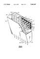
- FIG. 1is an isometric view illustrating all of the components of a coolant flow system in accordance with the embodiment of the present invention (except for an exterior housing) which is most desirable for very high planar packing density;
- FIG. 2is a cross-sectional side elevation view illustrating one embodiment of the present invention in which the supply and exhaust inlets are disposed on opposite edges of the substrate being cooled and which also illustrates the coolant supply flow and the coolant exhaust flow in different planes;
- FIG. 3is a view similar to that shown in FIG. 2 except that it more particularly illustrates the situation in which the supply inlet and the exhaust outlet are disposed on the same edge of the substrate being cooled;
- FIGS. 4 and 4Aare top and end views of a path defining structure in accordance with the present invention in which coolant flow restriction devices are employed to more particularly control coolant flow to various ones of the chips or modules being cooled so as to therefore make the overall system tunable;
- FIGS. 5 and 5Aare views similar to FIG. 4 except that rectangular as opposed to circular slots are shown.
- FIG. 6is an isometric view illustrating an alternative embodiment of the present invention.
- FIG. 1illustrates the essential features of the present invention.
- electronic chips or modules 30which are to be cooled.
- These devicesare shown in contact with heat sinks which include planar portions 20 and "a forest" of shafts 21 extending substantially perpendicular to planar portion 20.
- These heat sinks, having portions 20 and 21preferably, comprise a highly thermally conductive material such as a metal like aluminum.
- Shafts 21 extending from planar portions 20essentially provide surface area enhancement for fluid flow between the shafts.
- FIG. 1An essential aspect of FIG. 1 is path-defining structure 10 which includes interleaved supply channels 12 and exhaust channels 14.
- Supply channels 12include apertures 16 which are disposed adjacent to heat sink shafts 21.
- coolant fluidsuch as air
- entering supply channel 12passes through aperture 16 onto a heat sink structure. It initially passes through the heat sink in a direction substantially aligned with shafts 21. Subsequently, however, coolant fluid emerges from the heat sink structure in a plurality of different directions and enters exhaust channel 14.
- a surrounding housing(visible in FIGS. 2 and 3) provides the structure for the indicated closed fluid flow paths.
- Heat sink shafts 21are not limited to the specific structure shown.
- shafts 21may comprise any surface area enhancing structure which is a useful thermal conductor.
- shaftsmay actually comprise parallel plate fins or even fins disposed radially.
- the cross-section of the shaftsare not limited to square, rectangular or circular designs.
- the heat sink structureis optional. In such cases, coolant fluid flow impinges directly on the electronic component being cooled.
- chips or modules 30may be disposed as closely adjacent to one another as is practical. In point of fact, apart from issues with respect to connecting chips or modules 30 electrically to a substrate, there is nothing which prevents disposing these devices in an immediate adjacent relationship with one another.
- apertures 16may be selected to be of a size, dimension, spacing and configuration appropriate to the degree of cooling required by the module or chip which is disposed immediately below the aperture(s).
- path-defining structure 10comprises a material such as aluminum.
- the use of aluminum for this structureis advantageous in that it is lightweight, highly thermally conductive, and easily manufacturable, such as by extrusion methods.
- aluminumis easily machinable and the size of aperture 16 may be controlled and/or determined after manufacture of the base structure.
- the size of impingement apertures 16are controlled by the insertion therein of flow restriction devices such as appropriately sized grommets (see reference numeral 17 in FIG. 4).
- flow restriction devices and/or the individual sizing of apertures 16may be employed to achieve desired degrees of individualized cooling capabilities for different ones of the chips or modules.
- the structure illustrated in FIG. 1is also advantageous from a thermodynamic viewpoint.
- a low overall fluid flow resistanceis desired to achieve the greatest volume of fluid flow for any given pump or fan power level.
- exhaust channels 14which are larger than supply channels 12. This permits a more balanced flow without producing excessive pressure drops in either the supply or exhaust channels.
- most of the pressure dropoccurs within the "forest" of heat sink projections 21 and apertures 16.
- a plasticparticularly a high temperature plastic material, such as a polycarbonate
- the sizes of apertures 16may be determined in a plastic mold for the structure or may be later determined either by machining operations or by the inclusion of selected flow restriction devices, such as grommets, in the apertures.
- a plastic path-defining structureit is desirable to dispose therein metal wires, a metal grid, or electrically conductive particulate matter to provide any necessary or desirable electromagnetic shielding. Nonetheless, the shielding may also be provided by an appropriately designed exterior housing which itself may comprise either an electrically conductive material or a plastic material containing electrically conductive components.
- FIG. 2illustrates an alternate embodiment of the present invention in which it is particularly seen that the coolant fluid exits from an edge of the assembly opposite to that from which it enters.
- flow direction arrow 100that the fluid enters at inlet 41 and exits at outlet 42 as further indicated by flow direction arrow 101.
- the upper portion of housing 40is somewhat sloped so as to provide a more balanced coolant flow through impingement orifices 16 which are here shown as including optional shrouds 19 extending outwardly from the bottoms of impingement tubes 18 (see also more particularly FIG. 6, which are also optional but are required for shrouds 19).
- FIG. 3is similar to FIG.
- FIG. 3is a preferable embodiment when it is desired to have coolant fluid connections only on one side of the assembly.
- grommets 17within orifices 16, as shown in FIG. 4. These grommets may be all be of the same size or they may be selectively chosen in dependence on the thermal load of the chips or modules with which they are associated. Similarly, it is seen that the shape of the impingement orifice is not necessarily circular.
- FIG. 5illustrates rectangular orifices 16' together with flow control grommets 17' which may be inserted therewith for flow restriction purposes. Rectangular orifices are particularly useful in conjunction with parallel plate heat sinks. Circular orifices are useful in conjunction with heat sinks having fins disposed in a radial pattern.
- FIGS. 1-5 aboveeliminates a serious problem that exists in many cooling designs.
- air or other cooling fluidis passed over a heat sink from one direction and exits in another direction, the fluid picks up heat as it traverses each heat sink.
- Each subsequent row of modulestherefore is cooled by warmer and warmer cooling fluid.
- the second row of moduleswill not be cooled as well as the first nor will the third row be cooled as well as the second. This results in each row of modules operating at higher and higher temperatures.
- the total coolant flow rate chosenis usually determined by the cooling requirements that are associated with the last row of modules so that it is cooled to its desired temperature, considering the elevated thermal heat sink temperatures that have been previously experienced by the coolant flow as described above.
- the airflow ratecan therefore be set at a lower value since there is no preheating of the cooling air. This results in lower acoustic emissions and lower blower or pumping power requirements. Also, the operating temperature of all modules or chips are more nearly the same than with standard cross flow approaches.
- FIG. 6illustrates another embodiment of the present invention which also implements a highly parallel tunable impingement coolant fluid flow design.
- a coolant flow pathis defined at least in part by an exterior housing having side walls 47, sloped top wall 48, and rear wall 49.
- the bottom wall of the housingmay be a separately provided structure or it may comprise substrate 31.
- the interior of the housing in FIG. 6is divided into two parts by flow path-defining structure or divider 46 which includes impingement orifices 16 into which are inserted impingement or directing tubes 18 the bottoms of which preferably include shrouds 19 to better disperse the flow of coolant fluid through heat sink projections 21.
- flow path-defining structure or divider 46which includes impingement orifices 16 into which are inserted impingement or directing tubes 18 the bottoms of which preferably include shrouds 19 to better disperse the flow of coolant fluid through heat sink projections 21.
- the exhaust portionis preferably of a larger volume than the supply portion, which also is preferably tapered as shown. Nonetheless, the objectives of a highly parallel tunable impingement flow cooling scheme are still achieved.
- the coolant fluid flow assemblies shown in FIGS. 1-6achieve all of the objectives specified above.
- the resultant structureis efficient, compact, planar, tunable, and easily manufacturable and adjustable.
- the coolant distribution systemmay be operated without the inclusion of the heat sinks.
Landscapes
- Physics & Mathematics (AREA)
- Condensed Matter Physics & Semiconductors (AREA)
- General Physics & Mathematics (AREA)
- Engineering & Computer Science (AREA)
- Computer Hardware Design (AREA)
- Microelectronics & Electronic Packaging (AREA)
- Power Engineering (AREA)
- Cooling Or The Like Of Electrical Apparatus (AREA)
- Cooling Or The Like Of Semiconductors Or Solid State Devices (AREA)
Abstract
Description
Claims (16)
Priority Applications (1)
| Application Number | Priority Date | Filing Date | Title |
|---|---|---|---|
| US08/497,579US5604665A (en) | 1995-06-30 | 1995-06-30 | Multiple parallel impingement flow cooling with tuning |
Applications Claiming Priority (1)
| Application Number | Priority Date | Filing Date | Title |
|---|---|---|---|
| US08/497,579US5604665A (en) | 1995-06-30 | 1995-06-30 | Multiple parallel impingement flow cooling with tuning |
Publications (1)
| Publication Number | Publication Date |
|---|---|
| US5604665Atrue US5604665A (en) | 1997-02-18 |
Family
ID=23977435
Family Applications (1)
| Application Number | Title | Priority Date | Filing Date |
|---|---|---|---|
| US08/497,579Expired - LifetimeUS5604665A (en) | 1995-06-30 | 1995-06-30 | Multiple parallel impingement flow cooling with tuning |
Country Status (1)
| Country | Link |
|---|---|
| US (1) | US5604665A (en) |
Cited By (30)
| Publication number | Priority date | Publication date | Assignee | Title |
|---|---|---|---|---|
| US5912800A (en)* | 1997-09-03 | 1999-06-15 | International Business Machines Corporation | Electronic packages and method to enhance the passive thermal management of electronic packages |
| US6172416B1 (en)* | 1997-02-10 | 2001-01-09 | Matsushita Electric Industrial Co., Ltd. | Heat sink unit for cooling a plurality of exothermic units, and electronic apparatus comprising the same |
| US6462948B1 (en)* | 2001-06-25 | 2002-10-08 | Intel Corporation | Thermal management system for a multiple processor computer appliance |
| FR2825886A1 (en)* | 2001-06-12 | 2002-12-13 | Mitsubishi Electric Corp | ELECTRONIC APPARATUS AND ELECTRONIC EQUIPMENT USED FOR SAME |
| US20020189796A1 (en)* | 2001-04-17 | 2002-12-19 | White Joseph M. | Active heat sink structure with directed air flow |
| US20030025966A1 (en)* | 2001-08-03 | 2003-02-06 | Ross Halgren | OSP hardened WDM network |
| US6522540B2 (en)* | 2001-06-12 | 2003-02-18 | Mitsubishi Denki Kabushiki Kaisha | Device for radiating heat generating electronic parts, an electronic equipment having a heat radiating construction, and an electronic apparatus |
| DE10148520A1 (en)* | 2001-10-01 | 2003-04-17 | Fujitsu Siemens Computers Gmbh | Forced ventilation unit cooling computing equipment, has decoupling plane defining separate cooling air suction zone |
| EP1322057A1 (en)* | 2001-12-21 | 2003-06-25 | Redfern Broadband Networks Inc. | WDM add/drop multiplexer module |
| US20030128512A1 (en)* | 2001-12-21 | 2003-07-10 | Owens Mark J. | Improved vdm and/drop multiplexer module |
| US6765796B2 (en) | 2002-11-21 | 2004-07-20 | Teradyne, Inc. | Circuit board cover with exhaust apertures for cooling electronic components |
| EP1283550A3 (en)* | 2001-08-06 | 2004-12-22 | Kabushiki Kaisha Toshiba | Cooling device for heat-generating elements |
| US20050082035A1 (en)* | 2003-08-28 | 2005-04-21 | Bisuwasu Debashisu | Heat dissipating apparatus |
| US20050122687A1 (en)* | 2003-12-09 | 2005-06-09 | Dell Products L.P. | Interlocking heat sink |
| US20060048918A1 (en)* | 2001-02-09 | 2006-03-09 | Kabushiki Kaisha Toshiba | Cooling device for heat source |
| US20060187645A1 (en)* | 2005-02-23 | 2006-08-24 | Kabushiki Kaisha Toshiba | Heat dissipation device for electronic equipment |
| US20070074849A1 (en)* | 2005-10-04 | 2007-04-05 | Joshi Shrikant M | Heat sink with multiple coolant inlets |
| US20070285890A1 (en)* | 2006-06-13 | 2007-12-13 | Taiwan Semiconductor Manufacturing Co., Ltd. | Method and apparatus for increasing heat dissipation of high performance integrated circuits (ic) |
| US20080209931A1 (en)* | 2007-03-01 | 2008-09-04 | Jason Stevens | Data centers |
| US20090101316A1 (en)* | 2007-10-18 | 2009-04-23 | Evga Corporation | Heat dissipating assembly with reduced thermal gradient |
| US20090250195A1 (en)* | 2006-06-14 | 2009-10-08 | Toyota Jidosha Kabushiki Kaisha | Heat sink and cooler |
| US20090314467A1 (en)* | 2008-06-18 | 2009-12-24 | International Business Machines Corporation | Cooling apparatus and method of fabrication thereof with jet impingement structure integrally formed on thermally conductive pin fins |
| US7814965B1 (en)* | 2005-10-27 | 2010-10-19 | United States Thermoelectric Consortium | Airflow heat dissipation device |
| CN102467207A (en)* | 2010-11-19 | 2012-05-23 | 鸿富锦精密工业(深圳)有限公司 | Computer system and its radiator |
| US8325480B2 (en) | 2010-05-20 | 2012-12-04 | International Business Machines Corporation | Heat sink for distributing a thermal load |
| US8564952B2 (en) | 2011-07-25 | 2013-10-22 | International Business Machines Corporation | Flow boiling heat sink structure with vapor venting and condensing |
| US9061382B2 (en) | 2011-07-25 | 2015-06-23 | International Business Machines Corporation | Heat sink structure with a vapor-permeable membrane for two-phase cooling |
| US9069532B2 (en) | 2011-07-25 | 2015-06-30 | International Business Machines Corporation | Valve controlled, node-level vapor condensation for two-phase heat sink(s) |
| US10314203B1 (en)* | 2018-05-10 | 2019-06-04 | Juniper Networks, Inc | Apparatuses, systems, and methods for cooling electronic components |
| US11317540B2 (en)* | 2019-09-20 | 2022-04-26 | Samsung Electronics Co., Ltd. | Solid state drive apparatus and data storage apparatus including the same |
Citations (17)
| Publication number | Priority date | Publication date | Assignee | Title |
|---|---|---|---|---|
| US3843910A (en)* | 1971-10-18 | 1974-10-22 | Thomson Csf | Cooling system for components generating large amounts of heat |
| US4044515A (en)* | 1973-09-24 | 1977-08-30 | Hollingsead-Pryor Enterprises, Inc. | Gasket for an avionic tray |
| US4186945A (en)* | 1977-12-27 | 1980-02-05 | General Electric Company | Transition sleeve for a cabinet or the like |
| US4277816A (en)* | 1979-05-29 | 1981-07-07 | International Business Machines Corporation | Electronic circuit module cooling |
| US4291364A (en)* | 1979-12-26 | 1981-09-22 | International Business Machines Corporation | Air-cooled hybrid electronic package |
| US4296455A (en)* | 1979-11-23 | 1981-10-20 | International Business Machines Corporation | Slotted heat sinks for high powered air cooled modules |
| US5025856A (en)* | 1989-02-27 | 1991-06-25 | Sundstrand Corporation | Crossflow jet impingement heat exchanger |
| US5063476A (en)* | 1989-12-05 | 1991-11-05 | Digital Equipment Corporation | Apparatus for controlled air-impingement module cooling |
| US5083194A (en)* | 1990-01-16 | 1992-01-21 | Cray Research, Inc. | Air jet impingement on miniature pin-fin heat sinks for cooling electronic components |
| US5170320A (en)* | 1991-08-29 | 1992-12-08 | Hollingsead International, Inc. | Avionic tray and detachable metering plate |
| US5190241A (en)* | 1991-10-18 | 1993-03-02 | Hollingsead International, Inc. | Avionic tray and method of making same |
| US5196989A (en)* | 1990-04-09 | 1993-03-23 | Trw Inc. | Rigid circuit board structure using impingement cooling |
| US5315479A (en)* | 1993-01-21 | 1994-05-24 | Cray Research, Inc. | Air manifold for cooling electronic components |
| US5316075A (en)* | 1992-12-22 | 1994-05-31 | Hughes Aircraft Company | Liquid jet cold plate for impingement cooling |
| US5363654A (en)* | 1993-05-10 | 1994-11-15 | General Electric Company | Recuperative impingement cooling of jet engine components |
| US5435381A (en)* | 1990-09-14 | 1995-07-25 | Sundstrand Corporation | Shear flow/jet fin condenser |
| US5467815A (en)* | 1992-12-28 | 1995-11-21 | Abb Research Ltd. | Apparatus for impingement cooling |
- 1995
- 1995-06-30USUS08/497,579patent/US5604665A/ennot_activeExpired - Lifetime
Patent Citations (17)
| Publication number | Priority date | Publication date | Assignee | Title |
|---|---|---|---|---|
| US3843910A (en)* | 1971-10-18 | 1974-10-22 | Thomson Csf | Cooling system for components generating large amounts of heat |
| US4044515A (en)* | 1973-09-24 | 1977-08-30 | Hollingsead-Pryor Enterprises, Inc. | Gasket for an avionic tray |
| US4186945A (en)* | 1977-12-27 | 1980-02-05 | General Electric Company | Transition sleeve for a cabinet or the like |
| US4277816A (en)* | 1979-05-29 | 1981-07-07 | International Business Machines Corporation | Electronic circuit module cooling |
| US4296455A (en)* | 1979-11-23 | 1981-10-20 | International Business Machines Corporation | Slotted heat sinks for high powered air cooled modules |
| US4291364A (en)* | 1979-12-26 | 1981-09-22 | International Business Machines Corporation | Air-cooled hybrid electronic package |
| US5025856A (en)* | 1989-02-27 | 1991-06-25 | Sundstrand Corporation | Crossflow jet impingement heat exchanger |
| US5063476A (en)* | 1989-12-05 | 1991-11-05 | Digital Equipment Corporation | Apparatus for controlled air-impingement module cooling |
| US5083194A (en)* | 1990-01-16 | 1992-01-21 | Cray Research, Inc. | Air jet impingement on miniature pin-fin heat sinks for cooling electronic components |
| US5196989A (en)* | 1990-04-09 | 1993-03-23 | Trw Inc. | Rigid circuit board structure using impingement cooling |
| US5435381A (en)* | 1990-09-14 | 1995-07-25 | Sundstrand Corporation | Shear flow/jet fin condenser |
| US5170320A (en)* | 1991-08-29 | 1992-12-08 | Hollingsead International, Inc. | Avionic tray and detachable metering plate |
| US5190241A (en)* | 1991-10-18 | 1993-03-02 | Hollingsead International, Inc. | Avionic tray and method of making same |
| US5316075A (en)* | 1992-12-22 | 1994-05-31 | Hughes Aircraft Company | Liquid jet cold plate for impingement cooling |
| US5467815A (en)* | 1992-12-28 | 1995-11-21 | Abb Research Ltd. | Apparatus for impingement cooling |
| US5315479A (en)* | 1993-01-21 | 1994-05-24 | Cray Research, Inc. | Air manifold for cooling electronic components |
| US5363654A (en)* | 1993-05-10 | 1994-11-15 | General Electric Company | Recuperative impingement cooling of jet engine components |
Non-Patent Citations (4)
| Title |
|---|
| Doo, V. Y., et al., IBM Technical Disclosure Bulletin, "High Performance Package for Memory," vol. 21, No. 2, Jul. 1978, pp. 585-586. |
| Doo, V. Y., et al., IBM Technical Disclosure Bulletin, High Performance Package for Memory, vol. 21, No. 2, Jul. 1978, pp. 585 586.* |
| Eid, J. C., et al., Impingement Cooling Board ( ICB ), Research Disclosure (33058), Kenneth Mason Publications Ltd., England, Oct., 1991, No. 330, PO889 0346. 1 page.* |
| Eid, J. C., et al., Impingement Cooling Board (ICB), Research Disclosure (33058), Kenneth Mason Publications Ltd., England, Oct., 1991, No. 330, PO889-0346. 1 page. |
Cited By (54)
| Publication number | Priority date | Publication date | Assignee | Title |
|---|---|---|---|---|
| US6172416B1 (en)* | 1997-02-10 | 2001-01-09 | Matsushita Electric Industrial Co., Ltd. | Heat sink unit for cooling a plurality of exothermic units, and electronic apparatus comprising the same |
| US5912800A (en)* | 1997-09-03 | 1999-06-15 | International Business Machines Corporation | Electronic packages and method to enhance the passive thermal management of electronic packages |
| US7568519B2 (en)* | 2001-02-09 | 2009-08-04 | Kabushiki Kaisha Toshiba | Cooling device for heat source |
| US20060048918A1 (en)* | 2001-02-09 | 2006-03-09 | Kabushiki Kaisha Toshiba | Cooling device for heat source |
| US20020189796A1 (en)* | 2001-04-17 | 2002-12-19 | White Joseph M. | Active heat sink structure with directed air flow |
| US6755242B2 (en)* | 2001-04-17 | 2004-06-29 | Hewlett-Packard Development Company, L.P. | Active heat sink structure with directed air flow |
| FR2825886A1 (en)* | 2001-06-12 | 2002-12-13 | Mitsubishi Electric Corp | ELECTRONIC APPARATUS AND ELECTRONIC EQUIPMENT USED FOR SAME |
| US6522540B2 (en)* | 2001-06-12 | 2003-02-18 | Mitsubishi Denki Kabushiki Kaisha | Device for radiating heat generating electronic parts, an electronic equipment having a heat radiating construction, and an electronic apparatus |
| US6462948B1 (en)* | 2001-06-25 | 2002-10-08 | Intel Corporation | Thermal management system for a multiple processor computer appliance |
| US20030025966A1 (en)* | 2001-08-03 | 2003-02-06 | Ross Halgren | OSP hardened WDM network |
| EP1283550A3 (en)* | 2001-08-06 | 2004-12-22 | Kabushiki Kaisha Toshiba | Cooling device for heat-generating elements |
| DE10148520A1 (en)* | 2001-10-01 | 2003-04-17 | Fujitsu Siemens Computers Gmbh | Forced ventilation unit cooling computing equipment, has decoupling plane defining separate cooling air suction zone |
| US6804116B2 (en) | 2001-12-21 | 2004-10-12 | Redfern Broadband Networks Inc. | WDM add/drop multiplexer module |
| US20030117771A1 (en)* | 2001-12-21 | 2003-06-26 | Owens Mark J. | WDM add/drop multiplexer module |
| EP1322057A1 (en)* | 2001-12-21 | 2003-06-25 | Redfern Broadband Networks Inc. | WDM add/drop multiplexer module |
| US6822860B2 (en) | 2001-12-21 | 2004-11-23 | Redfern Broadband Networks Inc. | WDM add/drop multiplexer module |
| US20030128512A1 (en)* | 2001-12-21 | 2003-07-10 | Owens Mark J. | Improved vdm and/drop multiplexer module |
| US6795316B2 (en) | 2001-12-21 | 2004-09-21 | Redfern Broadband Networks, Inc. | WDM add/drop multiplexer module |
| US6765796B2 (en) | 2002-11-21 | 2004-07-20 | Teradyne, Inc. | Circuit board cover with exhaust apertures for cooling electronic components |
| US20050082035A1 (en)* | 2003-08-28 | 2005-04-21 | Bisuwasu Debashisu | Heat dissipating apparatus |
| US20050122687A1 (en)* | 2003-12-09 | 2005-06-09 | Dell Products L.P. | Interlocking heat sink |
| US6958914B2 (en)* | 2003-12-09 | 2005-10-25 | Dell Products L.P. | Interlocking heat sink |
| US20060187645A1 (en)* | 2005-02-23 | 2006-08-24 | Kabushiki Kaisha Toshiba | Heat dissipation device for electronic equipment |
| US7265984B2 (en) | 2005-02-23 | 2007-09-04 | Kabushiki Kaisha Toshiba | Heat dissipation device for electronic equipment |
| US7278468B2 (en)* | 2005-10-04 | 2007-10-09 | Delphi Technologies, Inc. | Heat sink with multiple coolant inlets |
| US20070074849A1 (en)* | 2005-10-04 | 2007-04-05 | Joshi Shrikant M | Heat sink with multiple coolant inlets |
| US7814965B1 (en)* | 2005-10-27 | 2010-10-19 | United States Thermoelectric Consortium | Airflow heat dissipation device |
| US20070285890A1 (en)* | 2006-06-13 | 2007-12-13 | Taiwan Semiconductor Manufacturing Co., Ltd. | Method and apparatus for increasing heat dissipation of high performance integrated circuits (ic) |
| US7583502B2 (en)* | 2006-06-13 | 2009-09-01 | Taiwan Semiconductor Manufacturing Co., Ltd. | Method and apparatus for increasing heat dissipation of high performance integrated circuits (IC) |
| US8291967B2 (en)* | 2006-06-14 | 2012-10-23 | Toyota Jidosha Kabushiki Kaisha | Heat sink and cooler |
| US20090250195A1 (en)* | 2006-06-14 | 2009-10-08 | Toyota Jidosha Kabushiki Kaisha | Heat sink and cooler |
| US20080209931A1 (en)* | 2007-03-01 | 2008-09-04 | Jason Stevens | Data centers |
| US20090101316A1 (en)* | 2007-10-18 | 2009-04-23 | Evga Corporation | Heat dissipating assembly with reduced thermal gradient |
| US20090314467A1 (en)* | 2008-06-18 | 2009-12-24 | International Business Machines Corporation | Cooling apparatus and method of fabrication thereof with jet impingement structure integrally formed on thermally conductive pin fins |
| US8266802B2 (en)* | 2008-06-18 | 2012-09-18 | International Business Machines Corporation | Cooling apparatus and method of fabrication thereof with jet impingement structure integrally formed on thermally conductive pin fins |
| US8325480B2 (en) | 2010-05-20 | 2012-12-04 | International Business Machines Corporation | Heat sink for distributing a thermal load |
| CN102467207A (en)* | 2010-11-19 | 2012-05-23 | 鸿富锦精密工业(深圳)有限公司 | Computer system and its radiator |
| US9078379B2 (en) | 2011-07-25 | 2015-07-07 | International Business Machines Corporation | Flow boiling heat sink with vapor venting and condensing |
| US9113581B2 (en) | 2011-07-25 | 2015-08-18 | International Business Machines Corporation | Valve controlled, node-level vapor condensation for two-phase heat sink(s) |
| US9061383B2 (en) | 2011-07-25 | 2015-06-23 | International Business Machines Corporation | Heat sink structure with a vapor-permeable membrane for two-phase cooling |
| US9067288B2 (en) | 2011-07-25 | 2015-06-30 | International Business Machines Corporation | Heat sink structure with a vapor-permeable membrane for two-phase cooling |
| US9069532B2 (en) | 2011-07-25 | 2015-06-30 | International Business Machines Corporation | Valve controlled, node-level vapor condensation for two-phase heat sink(s) |
| US8564952B2 (en) | 2011-07-25 | 2013-10-22 | International Business Machines Corporation | Flow boiling heat sink structure with vapor venting and condensing |
| US9075582B2 (en) | 2011-07-25 | 2015-07-07 | International Business Machines Corporation | Valve controlled, node-level vapor condensation for two-phase heat sink(s) |
| US9089936B2 (en) | 2011-07-25 | 2015-07-28 | International Business Machines Corporation | Heat sink structure with a vapor-permeable membrane for two-phase cooling |
| US9102021B2 (en) | 2011-07-25 | 2015-08-11 | International Business Machines Corporation | Heat sink structure with a vapor-permeable membrane for two-phase cooling |
| US9061382B2 (en) | 2011-07-25 | 2015-06-23 | International Business Machines Corporation | Heat sink structure with a vapor-permeable membrane for two-phase cooling |
| US9201474B2 (en) | 2011-07-25 | 2015-12-01 | International Business Machines Corporation | Valve controlled, node-level vapor condensation for two-phase heat sink(s) |
| US9446487B2 (en) | 2011-07-25 | 2016-09-20 | International Business Machines Corporation | Heat sink structure with a vapor-permeable membrane for two-phase cooling |
| US9623520B2 (en) | 2011-07-25 | 2017-04-18 | International Business Machines Corporation | Heat sink structure with a vapor-permeable membrane for two-phase cooling |
| US9687943B2 (en) | 2011-07-25 | 2017-06-27 | International Business Machines Corporation | Heat sink structure with a vapor-permeable membrane for two-phase cooling |
| US10314203B1 (en)* | 2018-05-10 | 2019-06-04 | Juniper Networks, Inc | Apparatuses, systems, and methods for cooling electronic components |
| US11317540B2 (en)* | 2019-09-20 | 2022-04-26 | Samsung Electronics Co., Ltd. | Solid state drive apparatus and data storage apparatus including the same |
| US11800686B2 (en) | 2019-09-20 | 2023-10-24 | Samsung Electronics Co., Ltd. | Solid state drive apparatus and data storage apparatus including the same |
Similar Documents
| Publication | Publication Date | Title |
|---|---|---|
| US5604665A (en) | Multiple parallel impingement flow cooling with tuning | |
| US5304846A (en) | Narrow channel finned heat sinking for cooling high power electronic components | |
| EP0274486B1 (en) | Parallel-flow air system for cooling electronic equipment | |
| US5294831A (en) | Circuit pack layout with improved dissipation of heat produced by high power electronic components | |
| US5063476A (en) | Apparatus for controlled air-impingement module cooling | |
| US5049982A (en) | Article comprising a stacked array of electronic subassemblies | |
| US5297005A (en) | Apparatus and method for cooling heat generating electronic components in a cabinet | |
| US6912128B2 (en) | Electronics cooling subassembly | |
| US6366461B1 (en) | System and method for cooling electronic components | |
| US6031720A (en) | Cooling system for semiconductor die carrier | |
| US5630469A (en) | Cooling apparatus for electronic chips | |
| US5535094A (en) | Integrated circuit package with an integral heat sink and fan | |
| US4291364A (en) | Air-cooled hybrid electronic package | |
| US6262891B1 (en) | Component holder with circulating air cooling of electrical components | |
| WO1995025255A1 (en) | Apparatus and method for cooling heat generating electronic components in a cabinet | |
| JPH09223883A (en) | Electronic equipment cooling device | |
| US6637505B1 (en) | Apparatus for cooling a box with heat generating elements received therein and a method for cooling same | |
| JPH02201999A (en) | Cooling plane device for cooling electronic circuit parts | |
| CN115226369A (en) | Device including thermal management mechanism and method of making same | |
| US6719038B2 (en) | Heat removal system | |
| KR0136070B1 (en) | Electronics | |
| US6493224B1 (en) | Method and apparatus to increase convection heat transfer in an electrical system and a method of manufacturing the same | |
| JPH06213588A (en) | Optimization of constitution of circuit pack and its heat sink | |
| CN120578269A (en) | Server device | |
| JPH0730273A (en) | Equipment with high heat generation package |
Legal Events
| Date | Code | Title | Description |
|---|---|---|---|
| AS | Assignment | Owner name:INTERNATIONAL BUSINESS MACHINES CORPORATION, NEW Y Free format text:ASSIGNMENT OF ASSIGNORS INTEREST;ASSIGNORS:CHRYSLER, GREGORY M.;CHU, RICHARD C.;KOENIG, RICHARD M.;REEL/FRAME:007574/0007 Effective date:19950627 | |
| STCF | Information on status: patent grant | Free format text:PATENTED CASE | |
| FEPP | Fee payment procedure | Free format text:PAYOR NUMBER ASSIGNED (ORIGINAL EVENT CODE: ASPN); ENTITY STATUS OF PATENT OWNER: LARGE ENTITY | |
| FPAY | Fee payment | Year of fee payment:4 | |
| AS | Assignment | Owner name:QUICKTURN DESIGN SYSTEMS, INC., CALIFORNIA Free format text:ASSIGNMENT OF ASSIGNORS INTEREST;ASSIGNOR:CADENCE DESIGN SYSTEMS, INC.;REEL/FRAME:012875/0648 Effective date:20020422 | |
| AS | Assignment | Owner name:CADENCE DESIGN SYSTEMS, INC., CALIFORNIA Free format text:ASSIGNMENT OF ASSIGNORS INTEREST;ASSIGNOR:INTERNATIONAL BUSINESS MACHINES CORPORATION;REEL/FRAME:012884/0893 Effective date:20020308 | |
| FPAY | Fee payment | Year of fee payment:8 | |
| FPAY | Fee payment | Year of fee payment:12 | |
| AS | Assignment | Owner name:CADENCE DESIGN SYSTEMS, INC., CALIFORNIA Free format text:ASSIGNMENT OF ASSIGNORS INTEREST;ASSIGNOR:QUICKTURN DESIGN SYSTEMS, INC.;REEL/FRAME:027789/0450 Effective date:20120227 |