US5603710A - Laser delivery system with soft tip - Google Patents
Laser delivery system with soft tipDownload PDFInfo
- Publication number
- US5603710A US5603710AUS08/514,663US51466395AUS5603710AUS 5603710 AUS5603710 AUS 5603710AUS 51466395 AUS51466395 AUS 51466395AUS 5603710 AUS5603710 AUS 5603710A
- Authority
- US
- United States
- Prior art keywords
- probe
- handpiece
- laser
- tube
- delivery system
- Prior art date
- Legal status (The legal status is an assumption and is not a legal conclusion. Google has not performed a legal analysis and makes no representation as to the accuracy of the status listed.)
- Expired - Lifetime
Links
- 239000000523sampleSubstances0.000claimsabstractdescription79
- 239000002184metalSubstances0.000claimsabstractdescription22
- 239000013307optical fiberSubstances0.000claimsabstractdescription15
- 238000001356surgical procedureMethods0.000claimsabstractdescription7
- 239000000463materialSubstances0.000claimsdescription7
- 238000003780insertionMethods0.000claimsdescription5
- 230000037431insertionEffects0.000claimsdescription5
- 239000012530fluidSubstances0.000abstractdescription7
- 230000006378damageEffects0.000abstractdescription4
- 208000014674injuryDiseases0.000abstractdescription4
- 208000027418Wounds and injuryDiseases0.000abstractdescription2
- 238000010992refluxMethods0.000description10
- 239000000853adhesiveSubstances0.000description6
- 230000001070adhesive effectEffects0.000description6
- 229920001296polysiloxanePolymers0.000description6
- 230000003287optical effectEffects0.000description5
- 238000005452bendingMethods0.000description3
- 238000010276constructionMethods0.000description2
- 238000000034methodMethods0.000description2
- 210000001525retinaAnatomy0.000description2
- 208000012260Accidental injuryDiseases0.000description1
- 238000004891communicationMethods0.000description1
- 239000000835fiberSubstances0.000description1
- 238000005286illuminationMethods0.000description1
- 238000004519manufacturing processMethods0.000description1
- 239000012528membraneSubstances0.000description1
- 210000000056organAnatomy0.000description1
- 229910001220stainless steelInorganic materials0.000description1
- 239000010935stainless steelSubstances0.000description1
- 230000008733traumaEffects0.000description1
Images

Classifications
- A—HUMAN NECESSITIES
- A61—MEDICAL OR VETERINARY SCIENCE; HYGIENE
- A61F—FILTERS IMPLANTABLE INTO BLOOD VESSELS; PROSTHESES; DEVICES PROVIDING PATENCY TO, OR PREVENTING COLLAPSING OF, TUBULAR STRUCTURES OF THE BODY, e.g. STENTS; ORTHOPAEDIC, NURSING OR CONTRACEPTIVE DEVICES; FOMENTATION; TREATMENT OR PROTECTION OF EYES OR EARS; BANDAGES, DRESSINGS OR ABSORBENT PADS; FIRST-AID KITS
- A61F9/00—Methods or devices for treatment of the eyes; Devices for putting in contact-lenses; Devices to correct squinting; Apparatus to guide the blind; Protective devices for the eyes, carried on the body or in the hand
- A61F9/007—Methods or devices for eye surgery
- A61F9/008—Methods or devices for eye surgery using laser
- A—HUMAN NECESSITIES
- A61—MEDICAL OR VETERINARY SCIENCE; HYGIENE
- A61B—DIAGNOSIS; SURGERY; IDENTIFICATION
- A61B17/00—Surgical instruments, devices or methods
- A61B17/28—Surgical forceps
- A61B2017/2808—Clamp, e.g. towel clamp
- A—HUMAN NECESSITIES
- A61—MEDICAL OR VETERINARY SCIENCE; HYGIENE
- A61B—DIAGNOSIS; SURGERY; IDENTIFICATION
- A61B90/00—Instruments, implements or accessories specially adapted for surgery or diagnosis and not covered by any of the groups A61B1/00 - A61B50/00, e.g. for luxation treatment or for protecting wound edges
- A61B90/08—Accessories or related features not otherwise provided for
- A61B2090/0801—Prevention of accidental cutting or pricking
- A61B2090/08021—Prevention of accidental cutting or pricking of the patient or his organs
- A—HUMAN NECESSITIES
- A61—MEDICAL OR VETERINARY SCIENCE; HYGIENE
- A61F—FILTERS IMPLANTABLE INTO BLOOD VESSELS; PROSTHESES; DEVICES PROVIDING PATENCY TO, OR PREVENTING COLLAPSING OF, TUBULAR STRUCTURES OF THE BODY, e.g. STENTS; ORTHOPAEDIC, NURSING OR CONTRACEPTIVE DEVICES; FOMENTATION; TREATMENT OR PROTECTION OF EYES OR EARS; BANDAGES, DRESSINGS OR ABSORBENT PADS; FIRST-AID KITS
- A61F9/00—Methods or devices for treatment of the eyes; Devices for putting in contact-lenses; Devices to correct squinting; Apparatus to guide the blind; Protective devices for the eyes, carried on the body or in the hand
- A61F9/007—Methods or devices for eye surgery
- A61F9/008—Methods or devices for eye surgery using laser
- A61F2009/00861—Methods or devices for eye surgery using laser adapted for treatment at a particular location
- A61F2009/00863—Retina
- Y—GENERAL TAGGING OF NEW TECHNOLOGICAL DEVELOPMENTS; GENERAL TAGGING OF CROSS-SECTIONAL TECHNOLOGIES SPANNING OVER SEVERAL SECTIONS OF THE IPC; TECHNICAL SUBJECTS COVERED BY FORMER USPC CROSS-REFERENCE ART COLLECTIONS [XRACs] AND DIGESTS
- Y10—TECHNICAL SUBJECTS COVERED BY FORMER USPC
- Y10S—TECHNICAL SUBJECTS COVERED BY FORMER USPC CROSS-REFERENCE ART COLLECTIONS [XRACs] AND DIGESTS
- Y10S604/00—Surgery
- Y10S604/902—Suction wands
Definitions
- the present inventionrelates to laser delivery systems and more particularly to such systems used in ophthalmic surgery and the like.
- lasersmay be used in ophthalmic surgery.
- the laser lightis transmitted from a laser source (which is disposed at some distance from the patient) through an optical fiber cable (which can be eight feet or so in length) to the patient.
- the optical fiber cableterminates proximally in a laser connector (for connection to the laser source) and terminates distally in a handpiece which is manipulated by the surgeon.
- the laser delivery systemcan be further improved.
- the eyeis a fragile organ and can be easily injured.
- the probewhich is inserted into the eye, is generally made from stainless steel. This is, of course, a rigid material, which, if inadvertently brought into contact with various structures of the eye, such as the retina, could easily injure the eye.
- Another objectis the provision of such a system which will protect the eye from accidental contact with the laser probe to reduce injury to the eye.
- a third objectis the provision of such a system which is reliable, yet relatively simple to manufacture.
- a laser delivery system of the present inventionis especially suited for ophthalmic surgery and the like.
- the systemincludes a handpiece, a laser connector, and an optical cable.
- the handpiecehas a handpiece body and a hollow probe of a size suitable for insertion into a human eye, which extends distally from the handpiece body.
- the laser connectoris suitably adapted for connection to a laser source.
- the optical fiber(terminating proximally in the laser connector and terminating distally in the handpiece) transmits laser light from a laser source to an eye to be treated.
- the optical fiberextends at least partially through the handpiece probe.
- the probeincludes a relatively hard proximal portion and a soft tip at its distal end to protect the eye from inadvertent contact with the hard portion of the probe, which could damage structures within the eye.
- the soft tipis a tube, preferably made of silicone, which is frictionally held in place by a bushing.
- the silicone tubeextends beyond the distal end of the hard proximal portion of the probe.
- the bushingextends distally a relatively short distance from the distal end of the hard portion of the probe to hold the silicone tip straight to prevent it from bending into the laser beam.
- the tubeis made from constant diameter tubing having a diameter comparable to the outer diameter of the probe. It is inserted into the hard portion of the probe by inserting the bushing into the tube, inserting the tube and bushing a small distance into the hard portion of the probe, and then pushing the bushing into the hard portion of the probe, thereby extruding the tube proximally inside the hard portion of the probe. This creates a tight friction fit which holds the tube in place without the use of adhesive.
- FIG. 1is a side view, with parts broken away for clarity, of the laser delivery system of the present invention
- FIG. 2is an enlarged sectional view taken along line 2--2 of FIG. 1;
- FIG. 3is an enlarged sectional view of the distal end of a handpiece
- FIG. 4is a further enlarged sectional view of the distal end of a probe of the handpiece taken along line 4--4 of FIG. 3;
- FIG. 5is an enlarged sectional view, similar to FIG. 1, illustrating the handpiece of an alternative embodiment of the present invention
- FIG. 6is a further enlarged sectional view of the distal end of the handpiece of FIG. 5, taken along line 6--6;
- FIG. 7is a sectional view, similar to FIG. 5, illustrating another embodiment of the present invention.
- a laser delivery system 11 of the present inventionincludes a handpiece 13, a laser connector 15, and an optical fiber cable 17.
- Handpiece 13has a handpiece body 18 made up of a handpiece proximal end portion 19, a handpiece distal end portion 21, and a reflux sleeve 23.
- a hollow probe 25 of a size suitable for insertion into a human eyeextends distally from the handpiece body.
- Probe 25preferably includes a metal tube or probe needle approximately one and three-quarters inches long which is suitably secured in the distal end of the handpiece body with approximately 1.38 inches of the tube exposed distally from the handpiece body.
- the outer diameter of the metal tubeis, for example, approximately 0.0355 inch, and its inner diameter is approximately 0.030 inch. These dimensions are illustrative of those for a tip suitable for insertion in the human eye.
- Laser connector 15may be of any desired construction suitable for connection to a laser source (not shown). The construction shown is illustrative only.
- optical fiber cable 17terminates proximally in laser connector 15 in such a manner that it is exposed to the laser light from the laser source.
- the optical cableextends for any desired length (such an eight feet or so) and terminates distally in the probe 25 of handpiece 13.
- Optical fiber cable 17thereby forms an optical path for the laser light from the laser source to an eye being treated.
- FIG. 1Also shown in FIG. 1 is a clamp 29 having jaws 29A used to removably secure cable 17 to any appropriate structure to hold the cable in place without significantly restricting movement of the handpiece by the surgeon.
- FIG. 2there is shown on a greatly enlarged scale the relationship between optical cable 17 and probe 25.
- the portion of optical cable 17 which is disposed in probe 25, namely an unsheathed optical fiber 17A,has an outer diameter of approximately 0.013", for example, while the inner diameter of the tip is approximately 0.020". This difference in diameter leaves a gap 31 disposed between the optical fiber and the tip. This gap runs the entire length of the tip and forms a fluid path from the distal end of probe 25 to the interior of the handpiece body.
- the optical fiberis not secured directly to probe 25 at all. Instead it is suitably secured to proximal end portion 19 of the handpiece body. Note as well that, although the optical fiber 17 is shown centered in probe 25 in FIG. 2, the fiber can in fact be off-center in the tip without closing off gap 31.
- the fluid path formed by gap 31is in fluid communication with a cavity 33 (FIG. 1) in handpiece distal end 21.
- Cavity 33is connected to a source of suction, as set forth in our above noted application. This allows fluid and other material to be withdrawn through the gap.
- the distal end of this fluid pathis disposed immediately adjacent the spot where the laser light exits the probe, so that removal of fluid from the operative site takes place almost exactly where needed.
- the distal end 41 (see FIGS. 3 and 4) of probe 25is provided with a tip 43 made of a soft pliable material, preferably silicone.
- This soft tipserves as a buffer between the structures of the eye and the metal portion of probe 25 (labelled 25A in FIG. 4), to prevent accidental injury to the eye structure caused by contact of the eye structure with the metal portion 25A of the probe.
- the tip 43is made from a tube of silicone 45 (FIGS. 2 and 4) which is received within the probe metal portion 25A. Tube 45 is not fixed by adhesive in probe portion 25A. Such adhesive may block or reduce the size of the gap 31 and hence interfere with the suction. Rather, tube 45 is frictionally held in place by a bushing 47 (FIGS. 2 and 4).
- Tube 45extends over bushing 47 and the bushing and tube are received within metal portion 25A of probe 25.
- Tip 43extends beyond the distal end of the metal portion of probe 25 by approximately 0.040"-0.050". Tip 43 is pliable and flexible and is thus bendable. It may thus bend to a point where it would interfere with the laser beam.
- Bushing 47extends beyond the metal portion of probe 25 by approximately 0.020" to add sufficient rigidity to tip 43 to prevent it from bending to a point where it would interfere with the laser beam.
- Soft tubing 45is preferably 0.037" in outer diameter. This is approximately equal to the outer diameter of probe metal portion 25A and is greater than the 0.030" inner diameter of the metal needle portion 25A of the probe (and also greater than the 0.020" inner diameter of bushing 47).
- the bushing 47is inserted within an elongate silicone tube having substantially constant inner and outer diameters. The tube is then scored with four 45° scores or two 90° scores spaced evenly around the tube approximately 0.025" past the end of the bushing. The tube is thus scored for a total of about 180°. Because the tube is pliable and deformable, it can be passed through the metal portion 25A of the probe until it extends out the back of the probe.
- the tubeis pulled into the metal portion 25A of the probe until the bushing is brought a short distance into metal portion 25A.
- a pull on the tube from the proximal end of the probebreaks the tube along the score lines and the excess is pulled from probe 25.
- the bushingis then pushed into the metal portion 25A of the probe, from the distal end of the probe, until it is inserted into the probe a desired amount.
- the tubelike the bushing 47, is only inserted into the metal portion 25A of the probe a short distance.
- the bushingBy pushing the bushing into the metal portion 25A of the probe to the position shown in FIG. 4, the bushing extrudes the tube proximally along the interior of the metal portion 25A.
- the tube 45extends for between 0.15"-0.20" from end to end when completed, only approximately 0.065" of tubing is used to produce the tip.
- a very tight frictional fitis produced which holds the tube in place without the use of adhesive.
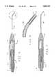
- a second embodiment of the present inventiondiffers from the previous embodiment in that the distal end of the probe (labelled 25A) is curved.
- Thisenables the surgeon to access parts of the posterior segment (the interior of the eye behind the lens) that a straight probe cannot reach. Except for the curve on the end, the curved and straight probes are identical.
- the distal end of the probeis curved to form an angle (such as the 40 degree angle shown in FIG. 5) with respect to the longitudinal axis of the probe and handpiece.
- the probeis preferably bent starting proximal to the soft tip 43 itself (as best seen in FIG. 6).
- the bendcould start at the tip itself, but that would complicate the bending process, and would not significantly improve the useability of the device by the surgeon.
- the particular radius of the curved portion of the tipcan vary, depending upon the desired application, a radius of approximately 1/4 was used in the device of FIGS. 5 and 6.
- FIG. 7yet another embodiment of the handpiece is shown.
- This handpiece, labelled 13Adiffers from that of FIG. 5 mainly in that the distal portion 21A of the handpiece does not include the reflux capability of the handpieces of FIGS. 1, and 5. It has no provision for passive aspiration.
- port 51 of the handpieceis connected to a syringe or a typical surgery machine that can supply suction for active aspiration.
- Handpiece 13Acan function well without reflux because of the soft tip 43 and the type of suction used. For example, if the surgeon uses passive aspiration with the device of FIG. 1, it is possible for a membrane or part of the retina to be caught on the probe tip. Because fragile tissue caught in the hard tip of FIG. 1 will probably tear if the surgeon tries to pull the probe away, the reflux capability of the probe of FIG. 1 allows the surgeon to reflux the captured material back into the eye without damage to these fragile tissues.
Landscapes
- Health & Medical Sciences (AREA)
- Ophthalmology & Optometry (AREA)
- Heart & Thoracic Surgery (AREA)
- Vascular Medicine (AREA)
- Optics & Photonics (AREA)
- Surgery (AREA)
- Engineering & Computer Science (AREA)
- Biomedical Technology (AREA)
- Physics & Mathematics (AREA)
- Nuclear Medicine, Radiotherapy & Molecular Imaging (AREA)
- Life Sciences & Earth Sciences (AREA)
- Animal Behavior & Ethology (AREA)
- General Health & Medical Sciences (AREA)
- Public Health (AREA)
- Veterinary Medicine (AREA)
- Laser Surgery Devices (AREA)
Abstract
Description
Claims (8)
Priority Applications (1)
| Application Number | Priority Date | Filing Date | Title |
|---|---|---|---|
| US08/514,663US5603710A (en) | 1993-04-15 | 1995-08-14 | Laser delivery system with soft tip |
Applications Claiming Priority (2)
| Application Number | Priority Date | Filing Date | Title |
|---|---|---|---|
| US08/048,149US5441496A (en) | 1993-04-15 | 1993-04-15 | Laser delivery system with soft tip |
| US08/514,663US5603710A (en) | 1993-04-15 | 1995-08-14 | Laser delivery system with soft tip |
Related Parent Applications (1)
| Application Number | Title | Priority Date | Filing Date |
|---|---|---|---|
| US08/048,149ContinuationUS5441496A (en) | 1993-04-15 | 1993-04-15 | Laser delivery system with soft tip |
Publications (1)
| Publication Number | Publication Date |
|---|---|
| US5603710Atrue US5603710A (en) | 1997-02-18 |
Family
ID=21952990
Family Applications (2)
| Application Number | Title | Priority Date | Filing Date |
|---|---|---|---|
| US08/048,149Expired - LifetimeUS5441496A (en) | 1993-04-15 | 1993-04-15 | Laser delivery system with soft tip |
| US08/514,663Expired - LifetimeUS5603710A (en) | 1993-04-15 | 1995-08-14 | Laser delivery system with soft tip |
Family Applications Before (1)
| Application Number | Title | Priority Date | Filing Date |
|---|---|---|---|
| US08/048,149Expired - LifetimeUS5441496A (en) | 1993-04-15 | 1993-04-15 | Laser delivery system with soft tip |
Country Status (1)
| Country | Link |
|---|---|
| US (2) | US5441496A (en) |
Cited By (37)
| Publication number | Priority date | Publication date | Assignee | Title |
|---|---|---|---|---|
| US5807383A (en)* | 1996-05-13 | 1998-09-15 | United States Surgical Corporation | Lasing device |
| US5954710A (en)* | 1996-02-13 | 1999-09-21 | El.En. S.P.A. | Device and method for eliminating adipose layers by means of laser energy |
| US6080143A (en)* | 1994-12-19 | 2000-06-27 | Connor; Christopher Sheldon | Intraocular slit illuminator and method therefor |
| US6135996A (en)* | 1998-04-17 | 2000-10-24 | Baxter International, Inc. | Controlled advancement lasing device |
| US6213998B1 (en) | 1998-04-02 | 2001-04-10 | Vanderbilt University | Laser surgical cutting probe and system |
| US6283955B1 (en) | 1996-05-13 | 2001-09-04 | Edwards Lifesciences Corp. | Laser ablation device |
| US20020107509A1 (en)* | 1999-09-30 | 2002-08-08 | Ceramoptec Industries, Inc. | Device for application of radiation |
| US6471692B1 (en)* | 1998-06-24 | 2002-10-29 | Laser Industries Ltd. | System and method for manipulating movement of an energy emitting device within a body cavity |
| US6491670B1 (en) | 2000-04-04 | 2002-12-10 | Duke University | Miniaturized surgical instruments especially useful for the opthalmologic surgical procedures and methods of making the same |
| US20030078568A1 (en)* | 2001-06-15 | 2003-04-24 | Diomed Inc. | Medical laser device |
| US20030088257A1 (en)* | 2001-11-06 | 2003-05-08 | Awh Carl C | Directional endo-illuminator |
| US6572608B1 (en)* | 1999-04-08 | 2003-06-03 | Eric T. Lee | Directional laser probe |
| US6575989B1 (en) | 1999-09-13 | 2003-06-10 | Synergetics, Inc. | Adjustable stiffness membrane scraper |
| US20030191461A1 (en)* | 2000-04-07 | 2003-10-09 | Synergetics, Inc., A Corporation | Directional laser probe |
| US20040034343A1 (en)* | 2002-08-16 | 2004-02-19 | Gillespie Walter D. | Articulation mechanism |
| US20040116912A1 (en)* | 2002-12-11 | 2004-06-17 | Appling William M. | Endovascular laser treatment device |
| US20050154379A1 (en)* | 2003-01-31 | 2005-07-14 | Innovatech Surgical, Inc. | Adjustable laser probe for use in vitreoretinal surgery |
| US6986766B2 (en)* | 2001-06-15 | 2006-01-17 | Diomed Inc. | Method of endovenous laser treatment |
| US20060217790A1 (en)* | 2005-03-28 | 2006-09-28 | Ohshin Mlp Co., Ltd. | Sheet-like face pack and kits for face packs |
| US20060247757A1 (en)* | 2003-09-30 | 2006-11-02 | Jotec Gmbh | Delivery system comprising a self expanding stent |
| WO2007006466A1 (en)* | 2005-07-14 | 2007-01-18 | Demetrio Romeo | Device for the treatment of glaucoma |
| US20070146632A1 (en)* | 2003-08-06 | 2007-06-28 | Arizona Board Of Reg, On Behalf Of The Univ. Of Az | Advanced polarization imaging method, apparatus, and computer program product for retinal imaging, liquid crystal testing, active remote sensing, and other applications |
| US20070260173A1 (en)* | 2006-05-05 | 2007-11-08 | Alcon, Inc. | Irrigation/aspiration tip |
| US20080208180A1 (en)* | 2002-07-10 | 2008-08-28 | Cartier William A | Endovascular treatment sheath having a heat insulative tip and method for using the same |
| US20080287938A1 (en)* | 2005-08-11 | 2008-11-20 | Synergetics, Inc. | Illuminated Directional Laser Probe |
| WO2009044424A1 (en) | 2007-10-05 | 2009-04-09 | El.En. S.P.A. | Device for the use, also single use, of an optical fiber for invasive surgical laser treatment in the human body |
| US20090216244A1 (en)* | 2004-11-30 | 2009-08-27 | Joel Pynson | Two Stage Plunger for Intraocular Lens Injector |
| DE112007002632T5 (en) | 2006-11-03 | 2009-12-31 | Iridex Corp., Mountain View | Illuminated laser probe treatment device with molded tip |
| US20100121260A1 (en)* | 2008-11-12 | 2010-05-13 | Ghannoum Ziad R | Distal Plastic End Infusion/Aspiration Tip |
| US20100125278A1 (en)* | 2008-11-19 | 2010-05-20 | Wagner Christopher E | Hard and Soft Tip Intraocular Lens Injector System and Method |
| US8545462B2 (en) | 2009-11-11 | 2013-10-01 | Alcon Research, Ltd. | Patch for irrigation/aspiration tip |
| US8784361B2 (en) | 2010-12-07 | 2014-07-22 | Alcon Research, Ltd. | Combined coaxial and bimanual irrigation/aspiration apparatus |
| US9335455B2 (en) | 2012-05-30 | 2016-05-10 | Cygnus, LP | Extended tip laser and illumination probe for retina surgery |
| US9370447B2 (en)* | 2011-10-10 | 2016-06-21 | Cygnus LP | Probes for use in ophthalmic and vitreoretinal surgery |
| US9433725B2 (en) | 2011-12-23 | 2016-09-06 | Alcon Research, Ltd. | Combined coaxial and bimanual irrigation/aspiration apparatus |
| US9839738B2 (en) | 2013-06-06 | 2017-12-12 | Novartis Ag | Transformer irrigation/aspiration device |
| US10022200B2 (en) | 2014-08-25 | 2018-07-17 | Peregrine Surgical, Ltd | Microsurgical instrument |
Families Citing this family (27)
| Publication number | Priority date | Publication date | Assignee | Title |
|---|---|---|---|---|
| US5441496A (en)* | 1993-04-15 | 1995-08-15 | Infinitech, Inc. | Laser delivery system with soft tip |
| US5611797A (en)* | 1995-07-26 | 1997-03-18 | Virginia C. George | Combination handpiece and surgical laser tool |
| US6015403A (en)* | 1996-02-26 | 2000-01-18 | Alcon Laboratories, Inc. | Ophthalmic surgery probe with soft tip |
| US7655002B2 (en) | 1996-03-21 | 2010-02-02 | Second Sight Laser Technologies, Inc. | Lenticular refractive surgery of presbyopia, other refractive errors, and cataract retardation |
| US5718677A (en)* | 1997-02-14 | 1998-02-17 | Alcon Laboratories, Inc. | Soft aspriation tip |
| IL121450A0 (en)* | 1997-08-01 | 1998-02-08 | Smollett Neil | Ophthalmic surgical equipment |
| US6800076B2 (en)* | 2000-10-18 | 2004-10-05 | Retinalabs, Inc. | Soft tip cannula and methods for use thereof |
| US9545338B2 (en) | 2006-01-20 | 2017-01-17 | Lensar, Llc. | System and method for improving the accommodative amplitude and increasing the refractive power of the human lens with a laser |
| US8262646B2 (en) | 2006-01-20 | 2012-09-11 | Lensar, Inc. | System and method for providing the shaped structural weakening of the human lens with a laser |
| US9889043B2 (en) | 2006-01-20 | 2018-02-13 | Lensar, Inc. | System and apparatus for delivering a laser beam to the lens of an eye |
| US10842675B2 (en) | 2006-01-20 | 2020-11-24 | Lensar, Inc. | System and method for treating the structure of the human lens with a laser |
| US8480659B2 (en) | 2008-07-25 | 2013-07-09 | Lensar, Inc. | Method and system for removal and replacement of lens material from the lens of an eye |
| US8500723B2 (en) | 2008-07-25 | 2013-08-06 | Lensar, Inc. | Liquid filled index matching device for ophthalmic laser procedures |
| US8382745B2 (en) | 2009-07-24 | 2013-02-26 | Lensar, Inc. | Laser system and method for astigmatic corrections in association with cataract treatment |
| JP2013500086A (en) | 2009-07-24 | 2013-01-07 | レンサー, インク. | System and method for performing a procedure using LADAR on an eye lens |
| US8758332B2 (en) | 2009-07-24 | 2014-06-24 | Lensar, Inc. | Laser system and method for performing and sealing corneal incisions in the eye |
| US8617146B2 (en) | 2009-07-24 | 2013-12-31 | Lensar, Inc. | Laser system and method for correction of induced astigmatism |
| CN102647954B (en) | 2009-07-24 | 2016-02-03 | 能斯雅有限公司 | A kind ofly provide the system and method for laser irradiation pattern for eye lens |
| WO2011094678A1 (en) | 2010-02-01 | 2011-08-04 | Lensar, Inc. | Purkinjie image-based alignment of suction ring in ophthalmic applications |
| EP4205633A1 (en) | 2010-10-15 | 2023-07-05 | Lensar, Inc. | System and method of scan controlled illumination of structures within an eye |
| USD694890S1 (en) | 2010-10-15 | 2013-12-03 | Lensar, Inc. | Laser system for treatment of the eye |
| USD695408S1 (en) | 2010-10-15 | 2013-12-10 | Lensar, Inc. | Laser system for treatment of the eye |
| US10463541B2 (en) | 2011-03-25 | 2019-11-05 | Lensar, Inc. | System and method for correcting astigmatism using multiple paired arcuate laser generated corneal incisions |
| US9393154B2 (en) | 2011-10-28 | 2016-07-19 | Raymond I Myers | Laser methods for creating an antioxidant sink in the crystalline lens for the maintenance of eye health and physiology and slowing presbyopia development |
| US9757536B2 (en)* | 2012-07-17 | 2017-09-12 | Novartis Ag | Soft tip cannula |
| US9730834B2 (en)* | 2013-12-20 | 2017-08-15 | Novartis Ag | Variable stiffness cannula and methods for a surgical system |
| US20150335376A1 (en)* | 2014-05-21 | 2015-11-26 | Covidien Lp | Multipurpose electrosurgical instrument with telescoping aspiration cannula |
Citations (3)
| Publication number | Priority date | Publication date | Assignee | Title |
|---|---|---|---|---|
| US5156604A (en)* | 1990-10-25 | 1992-10-20 | Messerschmitt-Bolkow-Blohm Gmbh | Small probing hook for arthroscopy |
| US5300063A (en)* | 1991-05-11 | 1994-04-05 | Nidek Co., Ltd. | Ophthalmic laser apparatus |
| US5441496A (en)* | 1993-04-15 | 1995-08-15 | Infinitech, Inc. | Laser delivery system with soft tip |
Family Cites Families (12)
| Publication number | Priority date | Publication date | Assignee | Title |
|---|---|---|---|---|
| US3865666A (en)* | 1973-05-08 | 1975-02-11 | Int Paper Co | Method of making a catheter |
| US4316465A (en)* | 1979-03-30 | 1982-02-23 | Dotson Robert S Jun | Ophthalmic handpiece with pneumatically operated cutter |
| US4299227A (en)* | 1979-10-19 | 1981-11-10 | Lincoff Harvey A | Ophthalmological appliance |
| US4583539A (en)* | 1982-01-12 | 1986-04-22 | Cornell Research Foundation, Inc. | Laser surgical system |
| US4537193A (en)* | 1982-10-28 | 1985-08-27 | Hgm, Inc. | Laser endocoagulator apparatus |
| US4607622A (en)* | 1985-04-11 | 1986-08-26 | Charles D. Fritch | Fiber optic ocular endoscope |
| US4702733A (en)* | 1985-11-22 | 1987-10-27 | Innovative Surgical Products, Inc. | Foot actuated pinch valve and high vacuum source for irrigation/aspiration handpiece system |
| US4857047A (en)* | 1987-01-27 | 1989-08-15 | Amoils Selig P | Finger operated vacuum bypass suction handpiece/holder apparatus for ocular cortex aspiration and refluxing |
| DE3831141A1 (en)* | 1988-09-13 | 1990-03-22 | Zeiss Carl Fa | METHOD AND DEVICE FOR MICROSURGERY ON EYE BY LASER RADIATION |
| US5120323A (en)* | 1990-01-12 | 1992-06-09 | Schneider (Usa) Inc. | Telescoping guide catheter system |
| US5192290A (en)* | 1990-08-29 | 1993-03-09 | Applied Medical Resources, Inc. | Embolectomy catheter |
| US5242449A (en)* | 1991-04-23 | 1993-09-07 | Allergan, Inc. | Ophthalmic instrument |
- 1993
- 1993-04-15USUS08/048,149patent/US5441496A/ennot_activeExpired - Lifetime
- 1995
- 1995-08-14USUS08/514,663patent/US5603710A/ennot_activeExpired - Lifetime
Patent Citations (3)
| Publication number | Priority date | Publication date | Assignee | Title |
|---|---|---|---|---|
| US5156604A (en)* | 1990-10-25 | 1992-10-20 | Messerschmitt-Bolkow-Blohm Gmbh | Small probing hook for arthroscopy |
| US5300063A (en)* | 1991-05-11 | 1994-04-05 | Nidek Co., Ltd. | Ophthalmic laser apparatus |
| US5441496A (en)* | 1993-04-15 | 1995-08-15 | Infinitech, Inc. | Laser delivery system with soft tip |
Cited By (54)
| Publication number | Priority date | Publication date | Assignee | Title |
|---|---|---|---|---|
| US6080143A (en)* | 1994-12-19 | 2000-06-27 | Connor; Christopher Sheldon | Intraocular slit illuminator and method therefor |
| US5954710A (en)* | 1996-02-13 | 1999-09-21 | El.En. S.P.A. | Device and method for eliminating adipose layers by means of laser energy |
| US6283955B1 (en) | 1996-05-13 | 2001-09-04 | Edwards Lifesciences Corp. | Laser ablation device |
| US5807383A (en)* | 1996-05-13 | 1998-09-15 | United States Surgical Corporation | Lasing device |
| US6213998B1 (en) | 1998-04-02 | 2001-04-10 | Vanderbilt University | Laser surgical cutting probe and system |
| US6458120B1 (en) | 1998-04-02 | 2002-10-01 | Jin Hui Shen | Laser surgical cutting probe and system |
| US6135996A (en)* | 1998-04-17 | 2000-10-24 | Baxter International, Inc. | Controlled advancement lasing device |
| US6471692B1 (en)* | 1998-06-24 | 2002-10-29 | Laser Industries Ltd. | System and method for manipulating movement of an energy emitting device within a body cavity |
| US6572608B1 (en)* | 1999-04-08 | 2003-06-03 | Eric T. Lee | Directional laser probe |
| US6575989B1 (en) | 1999-09-13 | 2003-06-10 | Synergetics, Inc. | Adjustable stiffness membrane scraper |
| US6660000B2 (en)* | 1999-09-30 | 2003-12-09 | Ceramoptec Industries, Inc. | Device for application of radiation |
| US20020107509A1 (en)* | 1999-09-30 | 2002-08-08 | Ceramoptec Industries, Inc. | Device for application of radiation |
| US6491670B1 (en) | 2000-04-04 | 2002-12-10 | Duke University | Miniaturized surgical instruments especially useful for the opthalmologic surgical procedures and methods of making the same |
| US20030191461A1 (en)* | 2000-04-07 | 2003-10-09 | Synergetics, Inc., A Corporation | Directional laser probe |
| US20060173448A1 (en)* | 2000-04-07 | 2006-08-03 | Scheller Gregg D | Directional laser probe |
| US7473249B2 (en) | 2000-04-07 | 2009-01-06 | Synergetics, Inc. | Directional laser probe |
| US7402158B2 (en) | 2000-04-07 | 2008-07-22 | Synergetics, Inc. | Directional laser probe |
| US6984230B2 (en) | 2000-04-07 | 2006-01-10 | Synergetics, Inc. | Directional laser probe |
| US20030078568A1 (en)* | 2001-06-15 | 2003-04-24 | Diomed Inc. | Medical laser device |
| US6981971B2 (en)* | 2001-06-15 | 2006-01-03 | Diomed Inc. | Medical laser device |
| US6986766B2 (en)* | 2001-06-15 | 2006-01-17 | Diomed Inc. | Method of endovenous laser treatment |
| US20030088257A1 (en)* | 2001-11-06 | 2003-05-08 | Awh Carl C | Directional endo-illuminator |
| US20080208180A1 (en)* | 2002-07-10 | 2008-08-28 | Cartier William A | Endovascular treatment sheath having a heat insulative tip and method for using the same |
| US6863668B2 (en)* | 2002-08-16 | 2005-03-08 | Edwards Lifesciences Corporation | Articulation mechanism for medical devices |
| US20040034343A1 (en)* | 2002-08-16 | 2004-02-19 | Gillespie Walter D. | Articulation mechanism |
| US7033347B2 (en)* | 2002-12-11 | 2006-04-25 | Angiodynamics, Inc. | Endovascular laser treatment device |
| US20040116912A1 (en)* | 2002-12-11 | 2004-06-17 | Appling William M. | Endovascular laser treatment device |
| US20050154379A1 (en)* | 2003-01-31 | 2005-07-14 | Innovatech Surgical, Inc. | Adjustable laser probe for use in vitreoretinal surgery |
| US7766904B2 (en) | 2003-01-31 | 2010-08-03 | Iridex Corporation | Adjustable laser probe for use in vitreoretinal surgery |
| US20070146632A1 (en)* | 2003-08-06 | 2007-06-28 | Arizona Board Of Reg, On Behalf Of The Univ. Of Az | Advanced polarization imaging method, apparatus, and computer program product for retinal imaging, liquid crystal testing, active remote sensing, and other applications |
| US7612880B2 (en)* | 2003-08-06 | 2009-11-03 | Arizona Board Of Regents On Behalf Of The University Of Arizona | Advanced polarization imaging method, apparatus, and computer program product for retinal imaging, liquid crystal testing, active remote sensing, and other applications |
| US20060247757A1 (en)* | 2003-09-30 | 2006-11-02 | Jotec Gmbh | Delivery system comprising a self expanding stent |
| US10667933B2 (en)* | 2003-09-30 | 2020-06-02 | Jotec Gmbh | Delivery system comprising a self expanding stent |
| US8535332B2 (en) | 2004-11-30 | 2013-09-17 | Bausch & Lomb Incorporated | Two stage plunger for intraocular lens injector |
| US8246631B2 (en) | 2004-11-30 | 2012-08-21 | Bausch & Lomb Incorporated | Two stage plunger for intraocular lens injector |
| US20090216244A1 (en)* | 2004-11-30 | 2009-08-27 | Joel Pynson | Two Stage Plunger for Intraocular Lens Injector |
| US20060217790A1 (en)* | 2005-03-28 | 2006-09-28 | Ohshin Mlp Co., Ltd. | Sheet-like face pack and kits for face packs |
| WO2007006466A1 (en)* | 2005-07-14 | 2007-01-18 | Demetrio Romeo | Device for the treatment of glaucoma |
| US8075553B2 (en) | 2005-08-11 | 2011-12-13 | Synergetics, Inc. | Illuminated directional laser probe |
| US20080287938A1 (en)* | 2005-08-11 | 2008-11-20 | Synergetics, Inc. | Illuminated Directional Laser Probe |
| US20070260173A1 (en)* | 2006-05-05 | 2007-11-08 | Alcon, Inc. | Irrigation/aspiration tip |
| DE112007002632T5 (en) | 2006-11-03 | 2009-12-31 | Iridex Corp., Mountain View | Illuminated laser probe treatment device with molded tip |
| WO2009044424A1 (en) | 2007-10-05 | 2009-04-09 | El.En. S.P.A. | Device for the use, also single use, of an optical fiber for invasive surgical laser treatment in the human body |
| US20100292681A1 (en)* | 2007-10-05 | 2010-11-18 | El.En. S.P.A. | Device for the use, also single use, of an optical fiber for invasive surgical laser treatment in the human body |
| US9351871B2 (en) | 2008-11-12 | 2016-05-31 | Alcon Research, Ltd. | Distal plastic end infusion/aspiration tip |
| US20100121260A1 (en)* | 2008-11-12 | 2010-05-13 | Ghannoum Ziad R | Distal Plastic End Infusion/Aspiration Tip |
| US20100125278A1 (en)* | 2008-11-19 | 2010-05-20 | Wagner Christopher E | Hard and Soft Tip Intraocular Lens Injector System and Method |
| US8545462B2 (en) | 2009-11-11 | 2013-10-01 | Alcon Research, Ltd. | Patch for irrigation/aspiration tip |
| US8784361B2 (en) | 2010-12-07 | 2014-07-22 | Alcon Research, Ltd. | Combined coaxial and bimanual irrigation/aspiration apparatus |
| US9370447B2 (en)* | 2011-10-10 | 2016-06-21 | Cygnus LP | Probes for use in ophthalmic and vitreoretinal surgery |
| US9433725B2 (en) | 2011-12-23 | 2016-09-06 | Alcon Research, Ltd. | Combined coaxial and bimanual irrigation/aspiration apparatus |
| US9335455B2 (en) | 2012-05-30 | 2016-05-10 | Cygnus, LP | Extended tip laser and illumination probe for retina surgery |
| US9839738B2 (en) | 2013-06-06 | 2017-12-12 | Novartis Ag | Transformer irrigation/aspiration device |
| US10022200B2 (en) | 2014-08-25 | 2018-07-17 | Peregrine Surgical, Ltd | Microsurgical instrument |
Also Published As
| Publication number | Publication date |
|---|---|
| US5441496A (en) | 1995-08-15 |
Similar Documents
| Publication | Publication Date | Title |
|---|---|---|
| US5603710A (en) | Laser delivery system with soft tip | |
| US6015403A (en) | Ophthalmic surgery probe with soft tip | |
| US5275593A (en) | Ophthalmic surgery probe assembly | |
| US5356407A (en) | Ophthalmic surgery probe assembly | |
| US5323766A (en) | Illuminating endo-photocoagulation probe | |
| US7766904B2 (en) | Adjustable laser probe for use in vitreoretinal surgery | |
| US8317778B2 (en) | Steerable and flexibly curved probes | |
| US20090093800A1 (en) | Flexible Surgical Probe | |
| US5630809A (en) | Intraocular slit illuminator and method therefor | |
| ATE168874T1 (en) | LASER DELIVERY DEVICE | |
| US20060122582A1 (en) | Device and method for dacryocystorhinostomy | |
| US20110125139A1 (en) | Multi-fiber flexible surgical probe | |
| KR20130008556A (en) | Multi-fiber flexible surgical probe | |
| DE60128107D1 (en) | MICRO-SURGICAL INJECTION AND / OR MOUNTABLE INSTRUMENTS AND SURGICAL DEVICE FOR THEIR USE | |
| CN106028908A (en) | Manufacturing an articulating ophthalmic surgical probe | |
| JP7514993B2 (en) | Ophthalmic Microsurgery Instruments | |
| US4878487A (en) | Illuminated tissue manipulator for ophthalmic surgery | |
| EP1450884A1 (en) | Apparatus and method for cannulating retinal blood vessels | |
| US11696852B2 (en) | Ophthalmic surgical instrument |
Legal Events
| Date | Code | Title | Description |
|---|---|---|---|
| FEPP | Fee payment procedure | Free format text:PAYOR NUMBER ASSIGNED (ORIGINAL EVENT CODE: ASPN); ENTITY STATUS OF PATENT OWNER: LARGE ENTITY | |
| STCF | Information on status: patent grant | Free format text:PATENTED CASE | |
| AS | Assignment | Owner name:INNOVATION MEDICAL TECHNOLOGIES, INC., TEXAS Free format text:MERGER;ASSIGNORS:INFINITECH, INC.;SURGICAL TECHNOLOGY, INC.;REEL/FRAME:009756/0125 Effective date:19981231 Owner name:ALCON LABORATORIES, INC., TEXAS Free format text:MERGER;ASSIGNOR:INNOVATION MEDICAL TECHNOLOGIES, INC.;REEL/FRAME:009756/0138 Effective date:19981231 | |
| FEPP | Fee payment procedure | Free format text:PAYER NUMBER DE-ASSIGNED (ORIGINAL EVENT CODE: RMPN); ENTITY STATUS OF PATENT OWNER: LARGE ENTITY Free format text:PAYOR NUMBER ASSIGNED (ORIGINAL EVENT CODE: ASPN); ENTITY STATUS OF PATENT OWNER: LARGE ENTITY | |
| FPAY | Fee payment | Year of fee payment:4 | |
| AS | Assignment | Owner name:ALCON MANUFACTURING, LTD., TEXAS Free format text:ASSIGNMENT OF ASSIGNORS INTEREST;ASSIGNOR:ALCON LABORATORIES, INC.;REEL/FRAME:011667/0559 Effective date:20010322 | |
| RR | Request for reexamination filed | Effective date:20010228 | |
| FPAY | Fee payment | Year of fee payment:8 | |
| B1 | Reexamination certificate first reexamination | Free format text:THE PATENTABILITY OF CLAIM 1, 2, 4, 5, 7 AND 8 IS CONFIRMED. CLAIMS 3 AND 6 ARE DETERMINED TO BE PATENTABLE AS AMENDED. NEW CLAIMS 9-12 ARE ADDED AND DETERMINED TO BE PATENTABLE. | |
| AS | Assignment | Owner name:ALCON RESEARCH, LTD., TEXAS Free format text:MERGER;ASSIGNOR:ALCON MANUFACTURING, LTD.;REEL/FRAME:021266/0729 Effective date:20080101 Owner name:ALCON RESEARCH, LTD.,TEXAS Free format text:MERGER;ASSIGNOR:ALCON MANUFACTURING, LTD.;REEL/FRAME:021266/0729 Effective date:20080101 | |
| FPAY | Fee payment | Year of fee payment:12 | |
| REMI | Maintenance fee reminder mailed | ||
| RR | Request for reexamination filed | Effective date:20090610 | |
| B2 | Reexamination certificate second reexamination | Free format text:CLAIM 3 IS CANCELLED. CLAIMS 1, 2, 4, 5, 6, 11 AND 12 ARE DETERMINED TO BE PATENTABLE AS AMENDED. CLAIMS 7-10, DEPENDENT ON AN AMENDED CLAIM, ARE DETERMINED TO BE PATENTABLE. |